JP4565291B2 - Information processing apparatus, information processing method, and program storage medium - Google Patents
Information processing apparatus, information processing method, and program storage medium Download PDFInfo
- Publication number
- JP4565291B2 JP4565291B2 JP2000024800A JP2000024800A JP4565291B2 JP 4565291 B2 JP4565291 B2 JP 4565291B2 JP 2000024800 A JP2000024800 A JP 2000024800A JP 2000024800 A JP2000024800 A JP 2000024800A JP 4565291 B2 JP4565291 B2 JP 4565291B2
- Authority
- JP
- Japan
- Prior art keywords
- password
- dial
- user
- display unit
- rotation operation
- Prior art date
- Legal status (The legal status is an assumption and is not a legal conclusion. Google has not performed a legal analysis and makes no representation as to the accuracy of the status listed.)
- Expired - Fee Related
Links
Images


Classifications
-
- G—PHYSICS
- G06—COMPUTING; CALCULATING OR COUNTING
- G06F—ELECTRIC DIGITAL DATA PROCESSING
- G06F1/00—Details not covered by groups G06F3/00 - G06F13/00 and G06F21/00
- G06F1/16—Constructional details or arrangements
- G06F1/1613—Constructional details or arrangements for portable computers
- G06F1/1633—Constructional details or arrangements of portable computers not specific to the type of enclosures covered by groups G06F1/1615 - G06F1/1626
- G06F1/1684—Constructional details or arrangements related to integrated I/O peripherals not covered by groups G06F1/1635 - G06F1/1675
- G06F1/169—Constructional details or arrangements related to integrated I/O peripherals not covered by groups G06F1/1635 - G06F1/1675 the I/O peripheral being an integrated pointing device, e.g. trackball in the palm rest area, mini-joystick integrated between keyboard keys, touch pads or touch stripes
-
- G—PHYSICS
- G06—COMPUTING; CALCULATING OR COUNTING
- G06F—ELECTRIC DIGITAL DATA PROCESSING
- G06F1/00—Details not covered by groups G06F3/00 - G06F13/00 and G06F21/00
- G06F1/16—Constructional details or arrangements
- G06F1/1613—Constructional details or arrangements for portable computers
- G06F1/1615—Constructional details or arrangements for portable computers with several enclosures having relative motions, each enclosure supporting at least one I/O or computing function
- G06F1/1616—Constructional details or arrangements for portable computers with several enclosures having relative motions, each enclosure supporting at least one I/O or computing function with folding flat displays, e.g. laptop computers or notebooks having a clamshell configuration, with body parts pivoting to an open position around an axis parallel to the plane they define in closed position
-
- G—PHYSICS
- G06—COMPUTING; CALCULATING OR COUNTING
- G06F—ELECTRIC DIGITAL DATA PROCESSING
- G06F1/00—Details not covered by groups G06F3/00 - G06F13/00 and G06F21/00
- G06F1/16—Constructional details or arrangements
- G06F1/1613—Constructional details or arrangements for portable computers
- G06F1/1633—Constructional details or arrangements of portable computers not specific to the type of enclosures covered by groups G06F1/1615 - G06F1/1626
- G06F1/1675—Miscellaneous details related to the relative movement between the different enclosures or enclosure parts
- G06F1/1679—Miscellaneous details related to the relative movement between the different enclosures or enclosure parts for locking or maintaining the movable parts of the enclosure in a fixed position, e.g. latching mechanism at the edge of the display in a laptop or for the screen protective cover of a PDA
-
- G—PHYSICS
- G06—COMPUTING; CALCULATING OR COUNTING
- G06F—ELECTRIC DIGITAL DATA PROCESSING
- G06F1/00—Details not covered by groups G06F3/00 - G06F13/00 and G06F21/00
- G06F1/16—Constructional details or arrangements
- G06F1/1613—Constructional details or arrangements for portable computers
- G06F1/1633—Constructional details or arrangements of portable computers not specific to the type of enclosures covered by groups G06F1/1615 - G06F1/1626
- G06F1/1684—Constructional details or arrangements related to integrated I/O peripherals not covered by groups G06F1/1635 - G06F1/1675
- G06F1/1686—Constructional details or arrangements related to integrated I/O peripherals not covered by groups G06F1/1635 - G06F1/1675 the I/O peripheral being an integrated camera
-
- G—PHYSICS
- G06—COMPUTING; CALCULATING OR COUNTING
- G06F—ELECTRIC DIGITAL DATA PROCESSING
- G06F21/00—Security arrangements for protecting computers, components thereof, programs or data against unauthorised activity
- G06F21/30—Authentication, i.e. establishing the identity or authorisation of security principals
- G06F21/31—User authentication
- G06F21/34—User authentication involving the use of external additional devices, e.g. dongles or smart cards
-
- G—PHYSICS
- G06—COMPUTING; CALCULATING OR COUNTING
- G06F—ELECTRIC DIGITAL DATA PROCESSING
- G06F2221/00—Indexing scheme relating to security arrangements for protecting computers, components thereof, programs or data against unauthorised activity
- G06F2221/21—Indexing scheme relating to G06F21/00 and subgroups addressing additional information or applications relating to security arrangements for protecting computers, components thereof, programs or data against unauthorised activity
- G06F2221/2131—Lost password, e.g. recovery of lost or forgotten passwords
Description
【0001】
【発明の属する技術分野】
本発明は情報処理装置、情報処理方法及びプログラム格納媒体に関し、例えばパーソナルコンピュータに適用して好適なものである。
【0002】
【従来の技術】
従来、パーソナルコンピュータ等の情報処理装置において、ユーザの正当性を確認する方法としてパスワードによるユーザ認証方法が広く用いられている。
【0003】
このパスワードによるユーザ認証方法を用いた情報処理装置においては、例えば起動時等の所定のタイミングにおいてユーザに対してパスワードの入力を要求し、入力されたパスワードと予め登録された登録パスワードとが一致したときにのみ、正当なユーザによる操作であると判断して当該情報処理装置の使用を許可するようになされている。
【0004】
【発明が解決しようとする課題】
ところが、かかるパスワードによるユーザ認証方法を用いた情報処理装置においては、ユーザはキーボードを操作してパスワードを入力しなければならないため操作が煩雑であり、またキーボードの操作に習熟していないユーザにとっては操作が困難であるという問題があった。
【0005】
また、かかるパスワードによるユーザ認証方法を用いた情報処理装置においては、短いパスワードは試行錯誤や類推によって解読され不正使用されることがあるという問題があり、解読を防止するため長い文字列をパスワードとして用いると当該パスワードをユーザ自身が記憶し難いという問題があった。
【0006】
本発明は以上の点を考慮してなされたもので、簡易な操作によってユーザ認証を行い得る情報処理装置、情報処理方法及びプログラム格納媒体を提案しようとするものである。
【0007】
【課題を解決するための手段】
かかる課題を解決するため本発明においては、操作手段と、操作手段による回転操作の動きに応じて割り当てられた0と1とを順次組み合わせることにより構成された入力の過程を示す操作パターンに基づいてダイヤルパスワードを生成するダイヤルパスワード生成手段と、ダイヤルパスワード生成手段によって生成されたダイヤルパスワードを登録パスワードとして記憶媒体に記憶する記憶手段と、ユーザが操作手段を用いて回転操作の動きに応じて割り当てられた0と1とを順次入力することにより構成された操作パターンに基づいて認証パスワードを生成する認証パスワード生成手段と、ユーザの入力操作によって生成された認証パスワードと予め記憶されている登録パスワードとを比較することにより回転操作の入力の過程での動きが一致しているか否かを判断するパスワード判断手段と、ダイヤル状の鍵を図式化して表示したダイヤルロック表示部とジョグダイヤルの回動操作及び押圧操作を図式化して表示したダイヤルウインドウ部とを表示部に表示するスクリーンロック表示手段と、パスワード判断手段により認証パスワードと登録パスワードとの回転操作の入力の過程での動きが一致していると判断された場合、正当なユーザであるとしてスクリーンロック表示手段に表示されたダイヤルロック表示部に表示されたスライド表示部を移動させることにより開錠したことをユーザに対し視認させるように制御する表示制御手段とを設けたことにより、ユーザは操作手段を回転操作するだけで入力の過程を示す操作パターン情報に基づいてパスワードを容易に入力することにより認証でき、かつ認証結果を表示部に図式で表示できるので、開錠したことを目視で視認できる。
【0008】
【発明の実施の形態】
以下図面について、本発明の一実施の形態を詳述する。
【0009】
(1)ジョグダイヤル付ノートブック型パーソナルコンピュータの構成
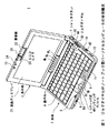
(1−1)ジョグダイヤル付ノートブック型パーソナルコンピュータの全体構成図1において、1は全体として情報処理装置としてのジョグダイヤル付ノートブック型パーソナルコンピュータ(以下、これをノートパソコンと呼ぶ)を示し、本体2と当該本体2に対して開閉自在に取り付けられた表示部3とによって構成されている。
【0010】
本体2には、その上面に各種文字や記号及び数字等を入力するための複数の操作キー4、マウスカーソルの移動に用いられるスティック式ポインティングデバイス(以下、これを単にスティックと呼ぶ)5、通常のマウスにおける左ボタン及び右ボタンに相当する左クリックボタン5A及び右クリックボタン5B、マウスカーソルをスクロールボタンに合わせることなくスクロールバーを操作するためのセンタボタン5C、内蔵スピーカ6及び表示部3に設けられたCCD(Charge Coupled Device) カメラ23用のシャッタボタン7が設けられている。
【0011】
表示部3には、正面にLCD(Liquid Crystal Display)でなる液晶ディスプレイ21が設けられており、正面の中央上端部にCCDカメラ23を備えた撮像部22が表示部3に対して回動自在に取り付けられている。
【0012】
すなわち撮像部22は、表示部3の正面方向及び背面方向との間の180度の角度範囲内で回動し、当該角度範囲内の任意の位置で位置決めし得るようになされている。また撮像部22には、CCDカメラ23のフォーカス調整を行う調整リング25が設けられており、当該CCDカメラ23によって所望の撮像対象を撮像する際のフォーカス調整を調整リング25の回動操作によって容易に行い得るようになされている。
【0013】
また表示部3には、撮像部22の左隣近傍にマイクロフォン24が設けられており、当該マイクロフォン24を介して表示部3の背面側からも集音し得るようになされている。
【0014】
さらに表示部3には、マイクロフォン24の左隣近傍にツメ13が設けられると共に、当該ツメ13と対応する本体2の所定位置に孔部8が設けられており、表示部3を本体2に閉塞した状態でツメ13が孔部8に嵌合されてロックするようになされている。
【0015】
本体2は、前側面にスライドレバー9が設けられており、当該スライドレバー9をスライドすることにより、孔部8に嵌合されたツメ13のロックを解除して表示部3を本体2に対して展開し得るようになされている。また本体2の前側面には、複数の吸気孔11が設けられている。
【0016】
さらに本体2の右側面には、排気孔12、PCMCIA(Personal Computer Memory Card International Association) 規格のPC(Personal Computer) カードに対応したPCカードスロット14及びモジュラージャック用のモデム端子15が設けられている。
【0017】
一方、図2に示すように本体2の左側面には、スライド式の電源スイッチ40、4ピン対応のIEEE(Institute of Electrical and Electronics Engineers) 1394端子41、USB(Universal Serial Bus)端子42、外部ディスプレイ用コネクタ46、マイクロフォン用入力端子43、ヘッドフォン端子44及びIrDA(Infrared Data Association) 準拠の赤外線ポート45が設けられている。
【0018】
さらに図3に示すように、本体2の後側面には外部電源コネクタ16が設けられており、底面にはバッテリパック(図示せず)を取り外すためのスライド式取り外しレバー18と、動作を中断して電源投入時の環境を再構成するためのリセットスイッチ19が設けられている。なお、バッテリパックはバッテリコネクタ17に対して着脱自在に接続される。
【0019】
かかる構成に加えて本体2の上面(図1)には、右端部においてバックスペースキーに相当する操作キー4Aとエンターキーに相当する操作キー4Bとの間に、当該操作キー4A及び4Bと同一高さになるようにジョグダイヤル30が組み込まれている。
【0020】
ここでジョグダイヤル30とは、ダイヤルの回動操作及び押圧操作によってシステムセッティングや各種アプリケーションソフトウェアにおける種々の機能を容易に実現し得る操作性の優れたユーザインターフェースである。
【0021】
このジョグダイヤル30は、図4に示すように平目模様の円板状操作つまみ218が本体2の外装ケース32から僅かに突出した状態で取り付けられており、円板状操作つまみ30Aによる矢印a方向及びb方向への回動操作に対応して所定の処理を実行すると共に、矢印c方向への押圧操作に対応して所定の処理を実行するようになされている。
【0022】
ちなみに円板状操作つまみ30Aにおいては、その回動操作において所定回転角度毎に軽い引っ掛かり(以下、これを回転クリックと呼ぶ)を生じるようになされており、当該回転クリックによって円板状操作つまみ30Aの回動操作量をユーザに対して触感を通じて通知し得るようになされている。
【0023】
(1−2)ジョグダイヤル付ノートブック型パーソナルコンピュータの回路構成図5に示すように、ノートパソコン1の本体2においては、当該本体2における各種機能を統括的に制御するCPU(Central Processing Unit) 50がホストバス52に接続されており、当該CPU50によってRAM(Random Access Memory)53にロードされた各種プログラムやアプリケーションソフトウェアに応じた処理を、クロックジェネレータ60から与えられるシステムクロックに基づいて所定の動作速度で実行することにより各種機能を実現し得るようになされている。
【0024】
またホストバス52には、キャッシュメモリ51が接続されており、CPU50が使用するデータをキャッシュし、高速アクセスを実現し得るようになされている。
【0025】
このホストバス52は、PCI(Peripheral Component Interconnect) バス55とホスト−PCIブリッジ54を介して接続されており、当該PCIバス55にはビデオコントローラ56、IEEE(Institute of Electrical and Electronics Engineers) 1394インターフェース57、ビデオキャプチャ処理チップ83及びPC(Personal Computer) カードインターフェース58が接続されている。
【0026】
ここでホスト−PCIブリッジ54は、CPU50とビデオコントローラ56、ビデオキャプチャ処理チップ83、IEEE1394インターフェース57及びPCカードインターフェース58との間で行われる各種データの授受を制御すると共に、メモリバス59を介して接続されたRAM53のメモリコントロールを行うようになされている。
【0027】
またホスト−PCIブリッジ54は、ビデオコントローラ56とAGP(Accelerated Graphics Port) に沿った信号線を介して接続されており、これによりホスト−PCIブリッジ54及びビデオコントローラ56間で画像データを高速転送し得るようになされている。
【0028】
ビデオキャプチャ処理チップ83は、シリアルバスでなるI2 Cバス82(一般的にSM(System Management) バスとも呼ばれている)と接続されており、当該I2 Cバス82を介してCCD(Charge Coupled Device) カメラ23で撮像された画像データが供給されると、これを内蔵のフレームメモリ(図示せず)に一旦格納し、JPEG(Joint Photographic Experts Group)規格に従って画像圧縮処理を施すことによりJPEG画像データを生成した後、当該JPEG画像データを再度フレームメモリに格納するようになされている。
【0029】
そしてビデオキャプチャ処理チップ83は、CPU50からの要求に応じてフレームメモリに格納されているJPEG画像データをバスマスタ機能を用いてRAM53へ直接転送した後、JPEG画像(静止画)データ又はMotionJPEG画像(動画)データとしてハードディスクドライブ(HDD)67へ転送する。
【0030】
ビデオコントローラ56は、CCD(Charge Coupled Device) カメラ23によって撮像された画像データや、ビデオキャプチャ処理チップ83のJPEG画像データに対して所定のグラフィックス処理を施した後、内蔵のVRAM(Video Random Access Memory)に格納して適宜読み出し、液晶ディスプレイ21に出力して表示させるようになされている。
【0031】
またビデオコントローラ56は、適時供給される各種アプリケーションソフトウェアに基づく画像データを液晶ディスプレイ21に出力することにより、複数のウィンドウ画面を表示し得るようになされている。
【0032】
PCカードインターフェース58は、オプション機能を追加するときにPCカードを介して適宜装着されるようになされており、PCカードを介して例えばCD−ROMドライブやDVDドライブ等の外部デバイスと接続し得るようになされている。
【0033】
IEEE1394インターフェース57は、IEEE1394端子41と直結されており、当該IEEE1394端子41を介して他のコンピュータ装置やディジタルビデオカメラ等の外部デバイスと接続し得るようになされている。
【0034】
PCIバス55は、ISA(Industrial Standard Architecture)バス65とPCI−ISAブリッジ66を介して接続されており、当該PCI−ISAブリッジ66にはHDD67及びUSB(Universal Serial Bus)端子42が接続されている。
【0035】
ここでPCI−ISAブリッジ66は、IDE(Integrated Drive Electronics)インターフェース、コンフィギュレーションレジスタ、RTC(Real-Time Clock) 回路及びUSBインターフェース等によって構成されており、クロックジェネレータ60から与えられるシステムクロックを基にIDEインターフェースを介してHDD67の制御を行う。
【0036】
HDD67のハードディスクには、Windows98(商標) 等のOS(Operating System)、電子メールプログラム、オートパイロットプログラム、キャプチャーソフトウェア、ジョグダイヤルユーティリティプログラム、ジョグダイヤルドライバ、スクリーンロックプログラム、さらにこれ以外の各種アプリケーションソフトウェアが記憶されており、起動処理の過程で適時RAM53に転送される。
【0037】
またPCI−ISAブリッジ66は、USB端子42を介して接続される図示しないフロッピーディスクドライブ、プリンタ及びUSBマウス等の外部デバイスを、USBインターフェースを介して制御すると共に、ISAバス65に接続されるモデム69及びサウンドコントローラ70の制御を行う。
【0038】
モデム69は、モデム端子15から図示しない公衆電話回線及びインターネットを介してインターネットサービスプロバイダ(以下、これをプロバイダと呼ぶ)に接続し、当該プロバイダとの間でアクセスするようになされている。サウンドコントローラ70は、マイクロフォン24から音声信号の取り込み及び内蔵スピーカ6に対する音声信号の供給を行う。
【0039】
またISAバス65には、I/O(In/Out)コントローラ73が接続されており、電源供給充電制御回路85を介して外部電源コネクタ84から電力の供給を受け、電源スイッチ40がオンされたときに各回路へ電力の供給を行う。なお、ここでもI/Oコントローラ73は、クロックジェネレータ60から供給されるシステムクロックを基に動作する。
【0040】
また電源供給充電制御回路85は、I/Oコントローラ73によって制御され、バッテリコネクタ17(図3)に接続されたバッテリパック86の充電を制御する。
【0041】
このI/Oコントローラ73はマイクロコントローラ、I/Oインターフェース、CPU、ROM及びRAM等によって構成されており、フラッシュメモリ79に格納されているBIOS(Basic Input/Output System) に基づいてOSやアプリケーションソフトウェアと液晶ディスプレイ21やHDD67等の各種周辺機器との間におけるデータの入出力を制御する。
【0042】
またI/Oコントローラ73は、赤外線ポート45と接続されており、例えば他のコンピュータ装置との間で赤外線通信を実行し得るようになされている。さらにI/Oコントローラ73は、反転スイッチ77と接続されており、CCDカメラ23の撮像部22が液晶ディスプレイ21の背面側方向に180度回転されたとき反転スイッチ77がオンされ、その旨をPCI−ISAブリッジ66及びホスト−PCIブリッジ54を介してCPU50に通知する。
【0043】
さらにI/Oコントローラ73は、全押し/半押しスイッチ78と接続されており、本体2の上面に設けられたシャッタボタン7が半押し状態にされたとき全押し/半押しスイッチ78がオンされ、その旨をCPU50に通知すると共に、シャッタボタン7が全押し状態にされたとき全押し/半押しスイッチ78がオンされ、その旨をCPU50に通知する。
【0044】
すなわちCPU50は、HDD67のハードディスクからキャプチャーソフトウェアをRAM53上に立ち上げた状態で、ユーザによってシャッタボタン7が半押し状態にされると静止画像モードに入り、CCDカメラ23を制御して静止画像のフリーズを実行し、全押し状態にされるとフリーズされた静止画像データを取り込みビデオコントローラ56に送出する。
【0045】
これに対してCPU50は、キャプチャーソフトウェアを立ち上げない状態で、ユーザによってシャッタボタン7が全押し状態にされると動画像モードに入り、最大60秒程度までの動画像を取り込みビデオコントローラ56に送出するようになされている。
【0046】
ところでI/Oコントローラ73のROMには、ウェイクアッププログラム、キー入力監視プログラム、LED制御プログラム及びジョグダイヤル状態監視プログラム、その他種々の制御プログラムが格納されている。
【0047】
ここでジョグダイヤル状態監視プログラムは、HDD67のハードディスクに格納されているジョグダイヤルユーティリティプログラムと関連したプログラムであり、ジョグダイヤル30が回動操作又は押圧操作されたか否かを監視するためのものである。
【0048】
ウェイクアッププログラムは、PCI−ISAブリッジ66内のRTC回路から供給される現在時刻が予め設定した開始時刻になると、CPU50によって所定の処理を実行するように制御されたプログラムであり、キー入力監視プログラムは操作キー4及び、その他の各種キースイッチからの入力を監視するプログラムである。
【0049】
LED制御プログラムは、電源ランプPL、電池ランプBL、メッセージランプML等のLED(Light Emitting Diode)でなる各種ランプの点灯を制御するプログラムである。
【0050】
またI/Oコントローラ73のRAMには、ウェイクアッププログラム用の設定時刻レジスタ、キー入力監視プログラム用のキー入力監視レジスタ、LED制御プログラム用のLED制御レジスタ及びジョグダイヤル状態監視プログラム用のI/Oレジスタ、その他の各種プログラム用のレジスタが設けられている。
【0051】
設定時刻レジスタは、ウェイクアッププログラムで用いるためにユーザが予め任意に設定した開始時刻の時間情報を格納するようになされている。従ってI/Oコントローラ73は、ウェイクアッププログラムに基づいてRTC回路から供給される現在時刻が任意に設定した開始時刻になったか否かを判別し、開始時刻になったときにはその旨をCPU50に通知する。これによりCPU50は、開始時刻になったとき予め設定された所定のアプリケーションソフトウェアを立ち上げ、当該アプリケーションソフトウェアに従って所定の処理を実行する。
【0052】
キー入力監視レジスタは、操作キー4、スティック5、左クリックボタン5A、右クリックボタン5B及びセンタボタン5Cの入力に基づいて操作キーフラグを格納するようになされている。
【0053】
従ってI/Oコントローラ73は、キー入力監視プログラムに基づいて例えばスティック5によるポインティング操作や、左クリックボタン5A、右クリックボタン5B及びセンタボタン5Cのクリック操作が行われたか否かを操作キーフラグの状態に基づいて判別し、ポインティング操作やクリック操作が行われたときにはその旨をCPU50に通知する。
【0054】
ここでポインティング操作とは、スティック5を指で上下左右に押圧操作することによりマウスカーソルを所望の位置に移動する操作のことであり、クリック操作とは左クリックボタン5A又は右クリックボタン5Bを指で素早く押して離す操作のことである。
【0055】
これによりCPU50は、ポインティング操作によるマウスカーソルの移動やクリック操作に応じた所定の処理を実行する。
【0056】
LED制御レジスタは、電源ランプPL、電池ランプBL、メッセージランプML等のLEDでなる各種ランプの点灯状態を示す点灯フラグを格納するようになされている。
【0057】
従ってI/Oコントローラ73は、例えばジョグダイヤル30の押圧操作によりCPU50がHDD67のハードディスクから電子メールプログラムを読み出してRAM53上で立ち上げ、当該電子メールプログラムに従って電子メールを受け取ったとき点灯フラグを格納すると共に、当該点灯フラグに基づいてLED81を制御することによりメッセージランプMLを点灯する。
【0058】
ジョグダイヤル状態監視プログラム用のI/Oレジスタは、ジョグダイヤル30に対して行われた回動操作及び押圧操作に応じてそれぞれ回動操作フラグ及び押圧操作フラグを格納するようになされている。
【0059】
従ってI/Oコントローラ73は、回転検出部88を介して接続されたジョグダイヤル30の回動操作及び押圧操作により複数のメニュー項目の中からユーザ所望のメニュー項目が選択されたとき、I/Oレジスタに回動操作フラグ及び押圧操作フラグを格納すると共に、その旨をCPU50に通知する。
【0060】
これによりCPU50は、HDD67から読み出してRAM53上で起動中のジョグダイヤルユーティリティプログラムに従って、ジョグダイヤル30の回動操作及び押圧操作によって決定されたメニュー項目に該当するアプリケーションソフトウェアを立ち上げて所定の処理を実行する。
【0061】
ここでI/Oコントローラ73は、電源スイッチ40がオフでOSが起動していない状態であっも、電源供給充電制御回路85の制御によってジョグダイヤル状態監視プログラムに基づいて常時動作しており、専用キーを設けることなく省電力状態又は電源オフ時においてもジョグダイヤル30の押圧操作によってユーザ所望のアプリケーションソフトウェアやスクリプトファイルを起動し得るようになされている。
【0062】
またI/Oコントローラ73は、I2 Cバス82と接続されており、操作キー4やジョグダイヤル30によって設定したCCDカメラ23に対する各種設定パラメータをI2 Cバス82を介して供給することにより、CCDカメラ23におけるカメラ電源のオン/オフを制御したり、CCDカメラ23における明るさやコントラストを調整するようになされている。
【0063】
(2)スクリーンロックプログラムによるジョグダイヤルを用いたユーザ認証処理
かかる構成に加えてノートパソコン1は、スクリーンロックプログラムに従って、予め設定された待機時間以上にわたって操作入力が途絶するとユーザが当該ノートパソコン1の近傍に存在しないものと判断し、所定のスクリーンセーバー画面(図示せず)を液晶ディスプレイ21(図1)に表示して当該ノートパソコン1の処理内容を示す画面表示を隠蔽するようになされている。
【0064】
そしてノートパソコン1は、スクリーンセーバー画面が表示された状態において何らかの操作キー4に対する操作入力を検出すると、液晶ディスプレイ21の中央に、スクリーンセーバー画面にオーバーラップして、図6(A)に示すスクリーンロック画面100を表示する。
【0065】
このスクリーンロック画面100が表示された状態においてノートパソコン1は、ユーザによって操作されたジョグダイヤル30の回動操作パターンとノートパソコン1に予め登録された回動操作パターンとを比較してユーザ認証処理を行い、これらが一致したとき正当なユーザによる操作入力であると判断してスクリーンセーバー画面の表示を終了して以降の操作を許可し、これらが一致しないとき正当なユーザによる操作入力ではないと判断してスクリーンセーバー画面の表示を継続し、これにより不正なユーザによる当該ノートパソコン1の操作を防止するようになされている。
【0066】
ここで回動操作パターンとは、ジョグダイヤル30を図4における矢印a方向(以下、この方向を左方向と呼ぶ)及び矢印b方向(以下、この方向を下方向と呼ぶ)に交互に往復して回動操作する際の、上方向及び下方向への回転クリック数の組合せパターン(例えば、「上に4回転クリック、下に2回転クリック、さらに上に1回転クリック」等)の事である。
【0067】
このようにノートパソコン1においては、スクリーンセーバー画面の表示を終了させるためのパスワードとして、ジョグダイヤル30の回動操作パターン(以下、これをダイヤルパスワードと呼ぶ)を用いてユーザ認証処理を行うようになされている。
【0068】
(2−1)ダイヤルパスワード登録処理
まず、ノートパソコン1におけるダイヤルパスワードの登録処理について説明する。
【0069】
ノートパソコン1のCPU50は、ユーザによる所定の操作に応じてHDD67からスクリーンロックプログラムを読み出してRAM53上に展開し、図7に示すダイヤルパスワード登録手順を実行する。
【0070】
すなわちCPU50はルーチンRT1の開始ステップから入ってステップSP1に移る。ステップSP1においてCPU50は、図8に示すダイヤルパスワード設定画面120を液晶ディスプレイ21に表示し、次のステップSP2に移る。
【0071】
図8に示すようにダイヤルパスワード設定画面120においては、ダイヤルパスワードの設定を行う設定ウィンドウ部121と、ジョグダイヤル30の回動操作及び押圧操作に応じた表示を行うことによりユーザに対してジョグダイヤル30の操作状態を視覚的に提供するジョグダイヤルウィンドウ部122を有している。
【0072】
ステップSP2においてCPU50は、設定ウィンドウ部121の第1の入力領域121Aを入力可能な状態(以下、この状態をアクティブと呼ぶ)にし、ユーザに対してダイヤルパスワードの入力を要求する。この状態においてユーザは、ジョグダイヤル30を任意の回動操作パターンで回動操作した後押圧操作し、当該回動操作パターンをダイヤルパスワードとして入力する。そしてCPU50は、ダイヤルパスワードが入力されると次のステップSP3に移る。
【0073】
ステップSP3においてCPU50は、設定ウィンドウ部121の第2の入力領域121Bをアクティブにし、ユーザに対してダイヤルパスワードの再入力を要求する。この状態においてユーザは、再度ジョグダイヤル30を任意の回動操作パターンで回動操作した後押圧操作してダイヤルパスワードを再入力する。そしてCPU50は、ダイヤルパスワードが再入力されると次のステップSP4に移る。
【0074】
ステップSP4においてCPU50は、第1の入力領域121Aに入力されたダイヤルパスワードと第2の入力領域121Bに再入力されたダイヤルパスワードとが一致するか否かを判断する。
【0075】
ステップSP4において否定結果が得られた場合、このことは第1の入力領域121Aに入力されたダイヤルパスワードと第2の入力領域121Bに再入力されたダイヤルパスワードとが一致しないこと、すなわちステップSP2においてダイヤルパスワードがユーザ所望の回動操作パターン通りに入力されていないことを表しており、CPU50はステップSP2に戻り、再度ダイヤルパスワードの入力を要求する。
【0076】
これに対してステップSP4において肯定結果が得られた場合、このことは第1の入力領域121Aに入力されたダイヤルパスワードと第2の入力領域121Bに再入力されたダイヤルパスワードとが一致したこと、すなわちステップSP2においてダイヤルパスワードがユーザ所望の回動操作パターン通りに入力されていることを表しており、CPU50は次のステップSP5に移る。
【0077】
ステップSP5においてCPU50は、入力されたダイヤルパスワードをHDD67内のレジストリに登録し、次のステップSP6に移る。
【0078】
ステップSP6においてCPU50は、ユーザがダイヤルパスワードを忘れた場合にスクリーンセーバー画面の表示を終了させるために用いる文字列パスワード(以下、これを緊急回避用パスワードと呼ぶ)を設定するための緊急回避用パスワード設定画面130(図9)を液晶ディスプレイ21に表示し、次のステップSP7に移る。
【0079】
ステップSP7においてCPU50は、第1の入力領域130Aをアクティブにし、ユーザに対して緊急回避用パスワードの入力を要求する。この状態においてユーザは、操作キー4を用いて任意の文字列を緊急回避用パスワードとして入力する。そしてCPU50は、第1の入力領域130Aに緊急回避用パスワードが入力されると次のステップSP8に移る。
【0080】
ステップSP8においてCPU50は、第2の入力領域130Bをアクティブにし、ユーザに対して緊急回避用パスワードの再入力を要求する。この状態においてユーザは再度緊急回避用パスワードを入力する。そしてCPU50は、第2の入力領域130Bに緊急回避用パスワードが再入力されると次のステップSP9に移る。
【0081】
ステップSP9においてCPU50は、第1の入力領域130Aに入力された緊急回避用パスワードと第2の入力領域130Bに再入力された緊急回避用パスワードとが一致するか否かを判断する。
【0082】
ステップSP9において否定結果が得られた場合、このことは第1の入力領域130Aに入力された緊急回避用パスワードと第2の入力領域130Bに再入力された緊急回避用パスワードとが一致しないこと、すなわちステップSP7において緊急回避用パスワードがユーザ所望の文字列通りに入力されていないことを表しており、CPU50はステップSP7に戻り、再度緊急回避用パスワードの入力を要求する。
【0083】
これに対してステップSP9において肯定結果が得られた場合、このことは第1の入力領域130Aに入力された緊急回避用パスワードと第2の入力領域130Bに再入力された緊急回避用パスワードとが一致したこと、すなわちステップSP7において緊急回避用パスワードがユーザ所望の文字列通りに入力されていることを表しており、CPU50は次のステップSP10に移る。
【0084】
ステップSP10においてCPU50は、入力された緊急回避用パスワードをHDD67内のレジストリに登録し、次のステップSP11に移って処理を終了する。
【0085】
かくしてノートパソコン1は、ユーザによって設定されたダイヤルパスワード及び緊急回避用パスワードをHDD67内のレジストリに登録する。
【0086】
ちなみに、ノートパソコン1においては、ジョグダイヤル30に対する上方向への回転操作を数字「1」で表すとともに下方向への回転操作を数字「0」で表し、ダイヤルパスワードの上及び下方向への回転クリック数に応じた数の数字「1」及び数字「0」の組合せによって表現したダイヤルパスワードデータを暗号化してレジストリに登録する。例えば、ダイヤルパスワードが「上方向に4回転クリック、下方向に2回転クリック、さらに上方向に1回転クリック」である場合、ダイヤルパスワードデータは「1111001」となる。
【0087】
またノートパソコン1においては、かかるダイヤルパスワードの登録完了後に、スクリーンセーバー設定画面(図示せず)における「パスワードによる保護」のチェックボックスをチェックすることにより、ダイヤルパスワードによるユーザ認証機能を有効にするようになされている。
【0088】
(2−2)ダイヤルパスワード認証処理
次に、ノートパソコン1におけるダイヤルパスワードによる認証処理について説明する。
【0089】
ノートパソコン1のCPU50は、スクリーンロックプログラムに従って図10に示すダイヤルパスワード認証手順を実行する。
【0090】
すなわち制御手段としてのCPU50はルーチンRT2の開始ステップから入ってステップSP21に移る。ステップSP21においてCPU50は、操作キー4、スティック5、ボタン5A〜5C、シャッタボタン7又はジョグダイヤル30を介したユーザによる操作入力を監視し、かかる操作入力が予め設定された待機時間以上にわたって途絶すると、次のステップSP22に移る。
【0091】
ステップSP22においてCPU50は、所定のスクリーンセーバー画面を液晶ディスプレイ21に表示してノートパソコン1の処理内容を示す画面表示を隠蔽し、次のステップSP23に移る。
【0092】
ステップSP23においてCPU50はユーザによる操作入力を監視し、当該操作入力を検出すると次のステップSP24に移る。
【0093】
ステップSP24においてCPU50は、ノートパソコン1においてジョグダイヤルユーティリティが起動しているか否かを判断する。
【0094】
ステップSP24において否定結果が得られた場合、このことはジョグダイヤルユーティリティが起動しておらず、ジョグダイヤル30の動作を受け付けないことを表しており、この場合ジョグダイヤル30によるダイヤルパスワードの入力が不可能なため、CPU50はステップSP32に移り、スクリーンセーバー画面の表示を終了した後ステップSP21に戻る。
【0095】
これに対してステップSP24において肯定結果が得られた場合、このことはジョグダイヤルユーティリティが起動しており、ジョグダイヤル30の動作を受け付けていることを表しており、CPU50は次のステップSP25に移る。
【0096】
ステップSP25においてCPU50は、スクリーンセーバー設定画面における「パスワードによる保護」のチェックボックスがチェックされているか否かを判断する。
【0097】
ステップSP25において否定結果が得られた場合、このことは「パスワードによる保護」のチェックボックスがチェックされていないことを表しており、CPU50はステップSP32に移り、スクリーンセーバー画面の表示を終了した後ステップSP21に戻る。
【0098】
これに対してステップSP25において肯定結果が得られた場合、このことは「パスワードによる保護」のチェックボックスがチェックされていることを表しており、CPU50は次のステップSP26に移る。
【0099】
ステップSP26においてCPU50は、図6(A)に示すスクリーンロック画面100を液晶ディスプレイ21に表示する。スクリーンロック画面100は、例えば金庫等に設けられているダイヤル鍵を図式化したダイヤルロック表示部101と、ジョグダイヤル30の回動操作及び押圧操作に応じた表示を行うジョグダイヤルウィンドウ部102とを有している。
【0100】
このスクリーンロック画面100が表示された状態において、ユーザは入力手段としてのジョグダイヤル30を任意の回動操作パターンで回動操作してダイヤルパスワードを入力する。
【0101】
このときCPU50は、ジョグダイヤル30の回動操作に応じて、ダイヤルロック表示部101の中央部に設けられたダイヤル表示部103を回動表示し、これによりあたかも実際にダイヤル鍵を操作しているかのような視覚効果をユーザに与え得るようになされている。またダイヤル表示部103の周縁部には等間隔に複数の目盛り103Aが設けられており、ジョグダイヤル30が1回転クリック分回転されると、CPU50はこれに応じてダイヤル表示部103を目盛り103Aの1目盛り分回転表示し、これによりジョグダイヤル30の回動操作をユーザに対して視覚的に確認させ得るようになされている。
【0102】
そして、ユーザによってジョグダイヤル30が押圧操作されてダイヤルパスワードの入力が完了すると、CPU50はこれに応じて次のステップSP27に移る。
【0103】
ステップSP27においてCPU50は、ユーザによって入力されたダイヤルパスワードとレジストリに登録されたダイヤルパスワードとが一致するか否かを判断する。
【0104】
ステップSP27において肯定結果が得られた場合、このことはユーザによって入力されたダイヤルパスワードとレジストリに登録されたダイヤルパスワードとが一致したこと、すなわち正当なユーザによる操作であることを表しており、CPU50はステップSP28に移る。
【0105】
ステップSP28においてCPU50は、図6(B)に示すようにダイヤルロック表示部101の左側部に設けられたスライド表示部104を矢印d方向に移動して表示し、これによりあたかも実際にダイヤル鍵が開いていくかのような視覚効果をユーザに与え得るようになされている。
【0106】
そしてCPU50はスライド表示部104の移動表示を完了するとステップSP32に移り、スクリーンセーバー画面の表示を終了した後に隠蔽していた画面表示を再度表示し、ステップSP21に戻る。
【0107】
これに対してステップSP27において否定結果が得られた場合、このことはユーザによって入力されたダイヤルパスワードとレジストリに登録されたダイヤルパスワードとが一致しないことを表しており、CPU50はステップSP29に移る。
【0108】
ステップSP29においてCPU50は、ステップSP27におけるダイヤルパスワードの不一致回数が3回以内か否かを判断する。
【0109】
ステップSP29において肯定結果が得られた場合、このことはステップSP27におけるダイヤルパスワードの不一致回数が3回以内であることを表しており、CPU50はステップSP27に戻る。
【0110】
これに対してステップSP29において否定結果が得られた場合、このことはステップSP27におけるダイヤルパスワードの不一致回数が3回以内ではないことを表しており、CPU50は次のステップSP30に移る。
【0111】
ステップSP30においてCPU50は、図11に示す緊急回避用パスワード入力画面140を表示し、ユーザに対して緊急回避用パスワードの入力を要求する。
【0112】
この緊急回避用パスワード入力画面140が表示された状態において、ユーザは操作キー4を介して緊急回避用パスワードを入力する。そしてCPU50は、ユーザによる緊急回避用パスワードの入力が完了すると、次のステップSP31に移る。
【0113】
ステップSP31においてCPU50は、ユーザによって入力された緊急回避用パスワードとレジストリに登録された緊急回避用パスワードとが一致するか否かを判断する。
【0114】
ステップSP31において否定結果が得られた場合、このことはユーザによって入力されたダイヤルパスワードとレジストリに登録されたダイヤルパスワードとが一致しないことを表しており、CPU50はステップSP30に戻る。
【0115】
これに対してステップSP31において肯定結果が得られた場合、このことはユーザによって入力されたダイヤルパスワードとレジストリに登録されたダイヤルパスワードとが一致したこと、すなわち正当なユーザによる操作であることを表しており、CPU50はステップSP32に移ってスクリーンセーバー画面の表示を終了した後ステップSP21に戻る。
【0116】
(3)実施の形態の動作及び効果
以上の構成において、ノートパソコン1は予め設定された待機時間以上にわたって操作入力が途絶すると、液晶ディスプレイ21にスクリーンセーバー画面を表示して、当該ノートパソコン1の処理内容を示す画面表示を隠蔽する。そしてノートパソコン1は、スクリーンセーバー画面が表示された状態において操作キー4に対する操作入力を検出すると、スクリーンセーバー画面の中央にスクリーンロック画面100を表示し、ユーザに対してダイヤルパスワードの入力を要求する。
【0117】
そしてノートパソコン1は、ユーザによるジョグダイヤル30の回動操作によって入力されたダイヤルパスワードとレジストリに登録されたダイヤルパスワードとを比較し、これらが一致しないとき正当なユーザによる操作入力ではないと判断してスクリーンセーバー画面の表示を継続し、これらが一致したとき正当なユーザによる操作入力であると判断してスクリーンセーバー画面の表示を終了する。
【0118】
従ってユーザはジョグダイヤル30を回動操作するだけで、スクリーンセーバー画面の表示を終了するためのダイヤルパスワードを容易に入力することができる。また、当該ダイヤルパスワードはジョグダイヤル30の回動操作パターンであるため、これによりユーザは当該ダイヤルパスワードを感覚的かつ容易に記憶することができる。
【0119】
またノートパソコン1は、ユーザによるジョグダイヤル30の回動操作に応じてダイヤルロック表示部101の中央部に設けられたダイヤル表示部103を回動表示するとともに、ユーザによって入力されたダイヤルパスワードとレジストリに登録されたダイヤルパスワードとが一致したときダイヤルロック表示部101の左側部に設けられたスライド表示部104を移動表示し、これによりあたかも実際にダイヤル鍵を操作して当該ダイヤル鍵を開いているかのような視覚効果をユーザに与えることができる。
【0120】
以上の構成によれば、ノートパソコン1はジョグダイヤル30の回動操作によって入力されたダイヤルパスワードとレジストリに登録されたダイヤルパスワードとを比較してユーザ認証を行うようにしたことにより、ユーザはダイヤルパスワードを感覚的かつ容易に記憶及び入力することができ、かくしてユーザに対して一段と操作性の優れたユーザインターフェースを提供することができる。
【0121】
また、ノートパソコン1はジョグダイヤル30の回動操作に応じてダイヤル表示部103を回動表示するとともに、ユーザ認証の結果に応じてスライド表示部104を移動表示するようにしたことにより、ユーザに視覚効果を与えながら、感覚的かつ容易に認証処理を実行せせることができる。
【0122】
(4)他の実施の形態
なお上述の実施の形態においては、ジョグダイヤル30の回動操作パターンに基づいてユーザ認証処理を行う場合について述べたが、本発明はこれに限らず、例えば、カーソルキー(上、下、左及び右方向の矢印キー)の操作パターンやマウスの移動操作パターン、あるいはキーボードの特定のキーの押下パターン等、他の様々な操作パターンに基づいてユーザ認証処理を行うようにしても良い。
【0123】
また上述の実施の形態においては、ジョグダイヤル30を上方向及び下方向に交互に往復する回動操作の操作パターンをダイヤルパスワードとして用いる場合について述べたが、本発明はこれに限らず、例えばジョグダイヤル30を上方向又は下方向の1方向に回転操作する操作パターンをダイヤルパスワードとして用いてユーザ認証を行うようにしても良い。
【0124】
また上述の実施の形態においては、ジョグダイヤル30の回動操作パターンに基づいてユーザ認証処理を行い、認証結果に基づいてスクリーンセーバー画面の表示を終了するようにしたが、本発明はこれに限らず、例えばノートパソコン1の起動時や特定のアプリケーションの起動時におけるユーザ認証処理等、様々なユーザ認証処理に適用しても良い。
【0125】
また上述の実施の形態においては、ノートパソコン1におけるユーザ認証処理について述べたが、本発明はこれに限らず、例えばPDA(Personal Digital Assistant:携帯情報端末)や携帯電話機等、様々な装置におけるユーザ認証処理に適用しても良い。
【0126】
さらに上述の実施の形態においては、CPU50がHDD67に格納されたスクリーンロックプログラムに基づいて、ダイヤルパスワードによるユーザ認証処理を行うようにしたが、本発明はこれに限らず、スクリーンロックプログラムの記録されたプログラム格納媒体をインストールすることにより、上述のユーザ認証処理を行うようにしても良い。
【0127】
このように上述した一連のユーザ認証処理を実行するスクリーンロックプログラムをノートパソコン1にインストールし、当該ノートパソコン1によって実行可能な状態とするために用いられるプログラム格納媒体としては、例えばフロッピーディスク、CD−ROM(Compact Disk-Read Only Memory )、DVD等のパッケージメディアのみならず、プログラムが一時的もしくは永続的に格納される半導体メモリや磁気ディスク等で実現しても良い。また、これらプログラム格納媒体にプログラムを格納する手段としては、ローカルエリアネットワークやインターネット、ディジタル衛星放送等の有線及び無線通信媒体を利用しても良く、ルータやモデム等の各種通信インターフェースを介在させて格納するようにしても良い。
【0128】
【発明の効果】
上述のように本発明によれば、操作手段と、操作手段による回転操作の動きに応じて割り当てられた0と1とを順次組み合わせることにより構成された入力の過程を示す操作パターンに基づいてダイヤルパスワードを生成するダイヤルパスワード生成手段と、ダイヤルパスワード生成手段によって生成されたダイヤルパスワードを登録パスワードとして記憶媒体に記憶する記憶手段と、ユーザが操作手段を用いて回転操作の動きに応じて割り当てられた0と1とを順次入力することにより構成された操作パターンに基づいて認証パスワードを生成する認証パスワード生成手段と、ユーザの入力操作によって生成された認証パスワードと予め記憶されている登録パスワードとを比較することにより回転操作の入力の過程での動きが一致しているか否かを判断するパスワード判断手段と、ダイヤル状の鍵を図式化して表示したダイヤルロック表示部とジョグダイヤルの回動操作及び押圧操作を図式化して表示したダイヤルウインドウ部とを表示部に表示するスクリーンロック表示手段と、パスワード判断手段により認証パスワードと登録パスワードとの回転操作の入力の過程での動きが一致していると判断された場合、正当なユーザであるとしてスクリーンロック表示手段に表示されたダイヤルロック表示部に表示されたスライド表示部を移動させることにより開錠したことをユーザに対し視認させるように制御する表示制御手段とを設けたことにより、ユーザは操作手段を回転操作するだけで入力した操作パターン情報に基づいて生成されたパスワードにより認証でき、かつ認証結果を表示部に図式で表示することにより、ユーザは表示部上で開錠したことを目視で視認できるので、ユーザに対して一段と操作性の優れた認証処理を実行させることができ、かくしてユーザに対して一段と操作性の優れた認証処理を実行させ得る情報処理装置を実現できる。
【図面の簡単な説明】
【図1】本発明によるジョグダイヤル付ノートブック型パーソナルコンピュータの全体構成を示す略線図である。
【図2】本体の左側面の構成を示す略線図である。
【図3】本体の後側面の及び底面の構成を示す略線図である。
【図4】本体に取り付けられているジョグダイヤルの外観を示す略線図である。
【図5】ジョグダイヤル付ノートブック型パーソナルコンピュータの回路構成を示すブロック図である。
【図6】スクリーンロック画面の構成を示す略線図である。
【図7】ダイヤルパスワード登録手順を示すフローチャートである。
【図8】ダイヤルパスワード設定画面の構成を示す略線図である。
【図9】緊急回避用パスワード設定画面の構成を示す略線図である。
【図10】ダイヤルパスワード認証手順を示すフローチャートである。
【図11】緊急回避用パスワード入力画面の構成を示す略線図である。
【符号の説明】
1……ノートパソコン、2……本体、3……表示部、4……操作キー、5……スティック式ポインティングデバイス、21……液晶ディスプレイ、30……ジョグダイヤル、50……CPU、53……RAM、67……HDD、73……I/Oコントローラ、88……回転検出部。[0001]
BACKGROUND OF THE INVENTION
The present inventionInformation processing apparatus, information processing method, andProgram storage mediumTo the bodyFor example, it is suitable for application to a personal computer.
[0002]
[Prior art]
Conventionally, in an information processing apparatus such as a personal computer, a user authentication method using a password has been widely used as a method for confirming the legitimacy of a user.
[0003]
In the information processing apparatus using the user authentication method using this password, for example, the user is requested to input the password at a predetermined timing such as at the time of start-up, and the input password matches the registered password registered in advance. Only when it is determined that the operation is performed by a legitimate user, the use of the information processing apparatus is permitted.
[0004]
[Problems to be solved by the invention]
However, in an information processing apparatus using a user authentication method using such a password, the user has to operate the keyboard and input the password, and thus the operation is complicated, and for users who are not familiar with keyboard operation. There was a problem that operation was difficult.
[0005]
Moreover, in an information processing apparatus using such a user authentication method using a password, there is a problem that a short password may be deciphered by trial and error or analogy and used illegally, and a long character string is used as a password to prevent deciphering. When used, there is a problem that it is difficult for the user to memorize the password.
[0006]
The present invention has been made in consideration of the above points, and user authentication can be performed by a simple operation.Information processing apparatus, information processing method, andProgram storage mediumBodyIt is what we are going to propose.
[0007]
[Means for Solving the Problems]
In order to solve this problem, in the present invention, an operating means and an operating meansA dial password generating means for generating a dial password based on an operation pattern indicating an input process configured by sequentially combining 0 and 1 assigned according to the movement of the rotation operation by the dial, and generated by the dial password generating means As a registered passwordStorage means for storing in a storage medium;An authentication password generating means for generating an authentication password based on an operation pattern configured by a user sequentially inputting 0 and 1 assigned in accordance with the movement of the rotation operation using the operation means; A password judgment means for judging whether or not the movement in the input process of the rotation operation is the same by comparing the authentication password generated by the above and a registered password stored in advance, and a dial-like key A screen lock display means for displaying a dial lock display section and a dial window section schematically showing a rotation operation and pressing operation of the jog dial on the display section, and an authentication password and a registered password by the password determination means. If it is determined that the movements in the input process of the rotation operation match, Display control means for controlling so as to visually recognize to the user that it has unlocking by moving the slide display unit displayed on the dial lock display portion displayed on the screen lock indicator means as isBy providing the user with the operation meansrotationJust operateShow input processOperation pattern informationSince it can authenticate by inputting a password easily based on this, and an authentication result can be displayed on a display part graphically, it can visually recognize that it unlocked.
[0008]
DETAILED DESCRIPTION OF THE INVENTION
Hereinafter, an embodiment of the present invention will be described in detail with reference to the drawings.
[0009]
(1) Configuration of notebook personal computer with jog dial
(1-1) Overall configuration of notebook personal computer with jog dial In FIG. 1,
[0010]
The
[0011]
The display unit 3 is provided with a
[0012]
That is, the imaging unit 22 is configured to rotate within an angle range of 180 degrees between the front direction and the back direction of the display unit 3 and to be positioned at an arbitrary position within the angular range. In addition, the imaging unit 22 is provided with an
[0013]
Further, the display unit 3 is provided with a
[0014]
Further, the display unit 3 is provided with a
[0015]
The
[0016]
Further, on the right side of the
[0017]
On the other hand, as shown in FIG. 2, on the left side of the
[0018]
Further, as shown in FIG. 3, an
[0019]
In addition to this configuration, the upper surface (FIG. 1) of the
[0020]
Here, the
[0021]
As shown in FIG. 4, the
[0022]
Incidentally, in the disk-shaped
[0023]
(1-2) Circuit Configuration of Notebook Personal Computer with Jog Dial As shown in FIG. 5, in the
[0024]
A
[0025]
The host bus 52 is connected to a PCI (Peripheral Component Interconnect) bus 55 via a host-
[0026]
Here, the host-
[0027]
The host-
[0028]
The video
[0029]
The video
[0030]
The
[0031]
The
[0032]
The
[0033]
The
[0034]
The PCI bus 55 is connected to an ISA (Industrial Standard Architecture)
[0035]
Here, the PCI-
[0036]
The hard disk of the
[0037]
The PCI-
[0038]
The
[0039]
Further, an I / O (In / Out)
[0040]
The power supply charging
[0041]
The I /
[0042]
The I /
[0043]
Further, the I /
[0044]
In other words, the
[0045]
On the other hand, the
[0046]
By the way, the ROM of the I /
[0047]
Here, the jog dial state monitoring program is a program related to the jog dial utility program stored in the hard disk of the
[0048]
The wake-up program is a program that is controlled by the
[0049]
The LED control program is a program for controlling lighting of various lamps including LEDs (Light Emitting Diodes) such as the power lamp PL, the battery lamp BL, and the message lamp ML.
[0050]
The RAM of the I /
[0051]
The set time register stores time information of a start time arbitrarily set in advance by the user for use in the wakeup program. Therefore, the I /
[0052]
The key input monitoring register stores operation key flags based on inputs from the operation key 4, the stick 5, the
[0053]
Therefore, the I /
[0054]
Here, the pointing operation is an operation of moving the mouse cursor to a desired position by pressing the stick 5 up / down / left / right with a finger, and the clicking operation refers to the
[0055]
Thereby, the
[0056]
The LED control register stores lighting flags indicating lighting states of various lamps including LEDs such as the power lamp PL, the battery lamp BL, and the message lamp ML.
[0057]
Therefore, for example, when the
[0058]
The I / O register for the jog dial state monitoring program stores a rotation operation flag and a pressing operation flag in accordance with the rotation operation and the pressing operation performed on the
[0059]
Accordingly, when the user-desired menu item is selected from among a plurality of menu items by rotating and pressing the
[0060]
As a result, the
[0061]
Here, the I /
[0062]
Also, the I /
[0063]
(2) User authentication process using jog dial by screen lock program
In addition to such a configuration, the
[0064]
When the
[0065]
In a state in which the
[0066]
Here, the rotation operation pattern means that the
[0067]
As described above, in the notebook
[0068]
(2-1) Dial password registration process
First, dial password registration processing in the
[0069]
The
[0070]
That is, the
[0071]
As shown in FIG. 8, in the dial
[0072]
In step SP2, the
[0073]
In step SP3, the
[0074]
In step SP4, the
[0075]
If a negative result is obtained in step SP4, this means that the dial password entered in the
[0076]
On the other hand, if a positive result is obtained in step SP4, this means that the dial password entered in the
[0077]
In step SP5, the
[0078]
In step SP6, the
[0079]
In step SP7, the
[0080]
In step SP8, the
[0081]
In step SP9, the
[0082]
If a negative result is obtained in step SP9, this means that the emergency avoidance password input in the
[0083]
On the other hand, when a positive result is obtained in step SP9, this means that the emergency avoidance password input in the
[0084]
In step SP10, the
[0085]
Thus, the
[0086]
By the way, in the
[0087]
In addition, in the
[0088]
(2-2) Dial password authentication processing
Next, an authentication process using a dial password in the
[0089]
The
[0090]
That is, the
[0091]
In step SP22, the
[0092]
In step SP23, the
[0093]
In step SP24, the
[0094]
If a negative result is obtained in step SP24, this means that the jog dial utility is not activated and the operation of the
[0095]
On the other hand, when a positive result is obtained in step SP24, this indicates that the jog dial utility is activated and the operation of the
[0096]
In step SP25, the
[0097]
If a negative result is obtained in step SP25, this indicates that the check box for "password protection" is not checked, and the
[0098]
On the other hand, if an affirmative result is obtained in step SP25, this indicates that the check box of “password protection” is checked, and the
[0099]
In step SP26, the
[0100]
In a state where the
[0101]
At this time, the
[0102]
When the user presses the
[0103]
In step SP27, the
[0104]
If an affirmative result is obtained in step SP27, this means that the dial password entered by the user and the dial password registered in the registry match, that is, the operation by a legitimate user. Moves to step SP28.
[0105]
In step SP28, the
[0106]
When the
[0107]
On the other hand, if a negative result is obtained in step SP27, this indicates that the dial password entered by the user does not match the dial password registered in the registry, and the
[0108]
In step SP29, the
[0109]
If an affirmative result is obtained in step SP29, this means that the number of dial password mismatches in step SP27 is within three, and the
[0110]
On the other hand, if a negative result is obtained in step SP29, this means that the number of mismatches of the dial password in step SP27 is not within three, and the
[0111]
In step SP30, the
[0112]
In a state where the emergency avoidance
[0113]
In step SP31, the
[0114]
If a negative result is obtained in step SP31, this means that the dial password entered by the user does not match the dial password registered in the registry, and the
[0115]
On the other hand, if a positive result is obtained in step SP31, this indicates that the dial password entered by the user matches the dial password registered in the registry, that is, an operation by a valid user. Then, the
[0116]
(3) Operation and effect of the embodiment
In the above configuration, when the operation input is interrupted for a preset standby time or longer, the notebook
[0117]
Then, the
[0118]
Therefore, the user can easily input the dial password for ending the display of the screen saver screen only by rotating the
[0119]
Further, the
[0120]
According to the above configuration, the
[0121]
In addition, the
[0122]
(4) Other embodiments
In the above-described embodiment, the case where the user authentication process is performed based on the rotation operation pattern of the
[0123]
Further, in the above-described embodiment, the case where the operation pattern of the rotation operation in which the
[0124]
In the above-described embodiment, the user authentication process is performed based on the rotation operation pattern of the
[0125]
In the above-described embodiment, the user authentication process in the notebook
[0126]
Further, in the above-described embodiment, the
[0127]
As a program storage medium used for installing the screen lock program for executing the above-described series of user authentication processes in the
[0128]
【The invention's effect】
As described above, according to the present invention, the operating means and the operating meansA dial password generating means for generating a dial password based on an operation pattern indicating an input process configured by sequentially combining 0 and 1 assigned according to the movement of the rotation operation by the dial, and generated by the dial password generating means As a registered passwordStorage means for storing in a storage medium;An authentication password generating means for generating an authentication password based on an operation pattern configured by a user sequentially inputting 0 and 1 assigned in accordance with the movement of the rotation operation using the operation means; A password judgment means for judging whether or not the movement in the input process of the rotation operation is the same by comparing the authentication password generated by the above and a registered password stored in advance, and a dial-like key A screen lock display means for displaying a dial lock display section and a dial window section schematically showing a rotation operation and pressing operation of the jog dial on the display section, and an authentication password and a registered password by the password determination means. If it is determined that the movements in the input process of the rotation operation match, By providing a display control means for controlling the user to visually recognize the unlocking by moving the slide display part displayed on the dial lock display part displayed on the screen lock display means. ,The user canrotationJust operateI input itOperation pattern informationBy displaying the authentication result graphically on the display unit, the user can visually recognize that the lock has been unlocked on the display unit. Can perform excellent authentication processing,ThusGreater operability for usersAn information processing apparatus capable of executing authentication processing can be realized.
[Brief description of the drawings]
FIG. 1 is a schematic diagram showing an overall configuration of a notebook personal computer with a jog dial according to the present invention.
FIG. 2 is a schematic diagram illustrating a configuration of a left side surface of the main body.
FIG. 3 is a schematic diagram illustrating a configuration of a rear side surface and a bottom surface of the main body.
FIG. 4 is a schematic diagram showing an appearance of a jog dial attached to the main body.
FIG. 5 is a block diagram showing a circuit configuration of a notebook personal computer with a jog dial.
FIG. 6 is a schematic diagram illustrating a configuration of a screen lock screen.
FIG. 7 is a flowchart showing a dial password registration procedure.
FIG. 8 is a schematic diagram illustrating a configuration of a dial password setting screen.
FIG. 9 is a schematic diagram illustrating a configuration of an emergency avoidance password setting screen.
FIG. 10 is a flowchart showing a dial password authentication procedure.
FIG. 11 is a schematic diagram illustrating a configuration of an emergency avoidance password input screen.
[Explanation of symbols]
DESCRIPTION OF
Claims (4)
上記操作手段による回転操作の動きに応じて割り当てられた0と1とを順次組み合わせることにより構成された入力の過程を示す操作パターンに基づいてダイヤルパスワードを生成するダイヤルパスワード生成手段と、
上記ダイヤルパスワード生成手段によって生成された上記ダイヤルパスワードを登録パスワードとして記憶媒体に記憶する記憶手段と、
ユーザが上記操作手段を用いて回転操作の動きに応じて割り当てられた0と1とを順次入力することにより構成された操作パターンに基づいて認証パスワードを生成する認証パスワード生成手段と、
上記ユーザの入力操作によって生成された上記認証パスワードと予め記憶されている上記登録パスワードとを比較することにより上記回転操作の入力の過程での動きが一致しているか否かを判断するパスワード判断手段と、
ダイヤル状の鍵を図式化して表示したダイヤルロック表示部とジョグダイヤルの回動操作及び押圧操作を図式化して表示したダイヤルウインドウ部とを表示部に表示するスクリーンロック表示手段と、
上記パスワード判断手段により上記認証パスワードと上記登録パスワードとの上記回転操作の入力の過程での動きが一致していると判断された場合、正当なユーザであるとして上記スクリーンロック表示手段に表示された上記ダイヤルロック表示部に表示されたスライド表示部を移動させることにより開錠したことを上記ユーザに対し視認させるように制御する表示制御手段と
を具える情報処理装置。Operation means;
And dialing the password generating means for generating a dial password based on the operation pattern showing a process input configured by combining the 0 assigned in accordance with the motion of the rotational operation by the upper Symbol operation means 1 and the sequence,
Storage means for storing the dial password generated by the dial password generation means in a storage medium as a registered password ;
An authentication password generating means for generating an authentication password based on an operation pattern configured by a user sequentially inputting 0 and 1 assigned according to the movement of the rotation operation using the operation means;
Password judging means for judging whether or not the movements in the input process of the rotation operation match by comparing the authentication password generated by the user's input operation and the registered password stored in advance. When,
A screen lock display means for displaying on the display section a dial lock display section that graphically displays a dial-like key and a dial window section that displays the rotation operation and pressing operation of the jog dial schematically;
When it is determined by the password determining means that the movement of the authentication password and the registered password in the process of inputting the rotation operation is the same, the password is displayed on the screen lock display means as a valid user. An information processing apparatus comprising: display control means for controlling the user to visually recognize that the lock is unlocked by moving the slide display unit displayed on the dial lock display unit .
請求項1に記載の情報処理装置。 In the operation pattern, 0 and 1 consisting of a combination of 1 assigned according to the number of rotation clicks in one direction of the rotation operation and a combination of 0 assigned according to the number of rotation clicks in the other direction, The information processing apparatus according to claim 1, wherein the pattern information is combined in order .
上記操作手段による回転操作の動きに応じて順次割り当てられた0と1との組み合わせコードで構成された入力過程の操作パターンに基づいてダイヤルパスワードを生成するダイヤルパスワード生成ステップと、
上記ダイヤルパスワード生成手段によって生成された上記ダイヤルパスワードを登録パスワードとして記憶媒体に記憶する記憶ステップと、
ユーザが上記操作手段を用いて回転操作の動きに応じて順次割り当てられた0と1との組み合わせコードを入力することにより構成された操作パターンに基づいて認証パスワードを生成する認証パスワード生成ステップと、
上記ユーザの入力操作によって生成された上記認証パスワードと予め記憶されている上記登録パスワードとを比較して上記回転操作の入力過程での動きが一致しているか否かを判断するパスワード判断ステップと、
ダイヤル状の鍵を図式化して表示したダイヤルロック表示部とジョグダイヤルの回動操作及び押圧操作を図式化して表示したダイヤルウインドウ部とを表示部に表示するスクリーンロック表示ステップと、
上記パスワード判断手段により上記認証パスワードと上記登録パスワードと
の上記回転操作の入力過程の動きが一致していると判断された場合、正当なユーザであるとして上記スクリーンロック表示手段に表示された上記ダイヤルロック表示部に表示されたスライド表示部を移動させることにより開錠したことを視認させるように制御する表示制御ステップと
を具える情報処理方法。An operation step for operating the operation means;
And dialing the password generation step of generating a dial password based on the operation pattern of the upper SL operating means sequentially assigned 0 and configuration input process in combination codes with one in accordance with the movement of the rotation operation by,
A storage step of storing the dial password generated by the dial password generation means in a storage medium as a registered password ;
An authentication password generation step of generating an authentication password based on an operation pattern configured by a user inputting a combination code of 0 and 1 sequentially assigned according to the movement of the rotation operation using the operation means;
A password determination step of comparing the authentication password generated by the user's input operation with the registered password stored in advance to determine whether or not the movements in the input process of the rotation operation match;
A screen lock display step for displaying on the display unit a dial lock display unit that graphically displays a dial-like key and a dial window unit that graphically displays the rotation operation and pressing operation of the jog dial;
The password determination means uses the authentication password and the registration password
When it is determined that the movements in the input process of the rotation operation match, the slide display unit displayed on the dial lock display unit displayed on the screen lock display unit is moved as an authorized user. An information processing method comprising: a display control step for performing control so that the unlocking is visually recognized .
操作手段に対して操作をおこなう操作ステップと、
上記操作手段による回転操作の動きに応じて順次割り当てられた0と1との組み合わせコードで構成された入力過程の操作パターンに基づいてダイヤルパスワードを生成するダイヤルパスワード生成ステップと、
上記ダイヤルパスワード生成手段によって生成された上記ダイヤルパスワードを登録パスワードとして記憶媒体に記憶する記憶ステップと、
ユーザが上記操作手段を用いて回転操作の動きに応じて順次割り当てられた0と1との組み合わせコードを入力することにより構成された操作パターンに基づいて認証パスワードを生成する認証パスワード生成ステップと、
上記ユーザの入力操作によって生成された上記認証パスワードと予め記憶されている上記登録パスワードとを比較して上記回転操作の入力過程での動きが一致しているか否かを判断するパスワード判断ステップと、
ダイヤル状の鍵を図式化して表示したダイヤルロック表示部とジョグダイヤルの回動操作及び押圧操作を図式化して表示したダイヤルウインドウ部とを表示部に表示するスクリーンロック表示ステップと、
上記パスワード判断手段により上記認証パスワードと上記登録パスワードと
の上記回転操作の入力過程の動きが一致していると判断された場合、正当なユーザであるとして上記スクリーンロック表示手段に表示された上記ダイヤルロック表示部に表示されたスライド表示部を移動させることにより開錠したことを視認させるように制御する表示制御ステップと
からなるプログラムを実行させるプログラム格納媒体。For information processing equipment
An operation step for operating the operation means;
And dialing the password generation step of generating a dial password based on the operation pattern of the upper SL operating means sequentially assigned 0 and configuration input process in combination codes with one in accordance with the movement of the rotation operation by,
A storage step of storing the dial password generated by the dial password generation means in a storage medium as a registered password ;
An authentication password generation step of generating an authentication password based on an operation pattern configured by a user inputting a combination code of 0 and 1 sequentially assigned according to the movement of the rotation operation using the operation means;
A password determination step of comparing the authentication password generated by the user's input operation with the registered password stored in advance to determine whether or not the movements in the input process of the rotation operation match;
A screen lock display step for displaying on the display unit a dial lock display unit that graphically displays a dial-like key and a dial window unit that graphically displays the rotation operation and pressing operation of the jog dial;
The password determination means uses the authentication password and the registration password
When it is determined that the movements in the input process of the rotation operation match, the slide display unit displayed on the dial lock display unit displayed on the screen lock display unit is moved as an authorized user. A program storage medium for executing a program comprising: a display control step for performing control so as to visually recognize unlocking .
Priority Applications (2)
| Application Number | Priority Date | Filing Date | Title |
|---|---|---|---|
| JP2000024800A JP4565291B2 (en) | 2000-01-28 | 2000-01-28 | Information processing apparatus, information processing method, and program storage medium |
| US09/771,324 US20010027529A1 (en) | 2000-01-28 | 2001-01-26 | Authentication device, authentication method, program storage medium and information processing device |
Applications Claiming Priority (1)
| Application Number | Priority Date | Filing Date | Title |
|---|---|---|---|
| JP2000024800A JP4565291B2 (en) | 2000-01-28 | 2000-01-28 | Information processing apparatus, information processing method, and program storage medium |
Publications (3)
| Publication Number | Publication Date |
|---|---|
| JP2001209615A JP2001209615A (en) | 2001-08-03 |
| JP2001209615A5 JP2001209615A5 (en) | 2005-12-15 |
| JP4565291B2 true JP4565291B2 (en) | 2010-10-20 |
Family
ID=18550732
Family Applications (1)
| Application Number | Title | Priority Date | Filing Date |
|---|---|---|---|
| JP2000024800A Expired - Fee Related JP4565291B2 (en) | 2000-01-28 | 2000-01-28 | Information processing apparatus, information processing method, and program storage medium |
Country Status (2)
| Country | Link |
|---|---|
| US (1) | US20010027529A1 (en) |
| JP (1) | JP4565291B2 (en) |
Families Citing this family (19)
| Publication number | Priority date | Publication date | Assignee | Title |
|---|---|---|---|---|
| US20030170011A1 (en) * | 2001-09-24 | 2003-09-11 | Masato Otsuka | System and method for seamless navigation between local and external documents in an optical disc player |
| US20030177349A1 (en) * | 2002-03-15 | 2003-09-18 | Kevin Hersh | Systems and methods for authenticating a user for a computing device |
| JP4701615B2 (en) * | 2004-01-23 | 2011-06-15 | ソニー株式会社 | Information storage device |
| US7616764B2 (en) * | 2004-07-07 | 2009-11-10 | Oracle International Corporation | Online data encryption and decryption |
| US7596701B2 (en) * | 2004-07-07 | 2009-09-29 | Oracle International Corporation | Online data encryption and decryption |
| US8458619B2 (en) | 2004-12-14 | 2013-06-04 | International Business Machines Corporation | Method, system and program product for screensaver breakthrough of prioritized messages |
| US7908645B2 (en) * | 2005-04-29 | 2011-03-15 | Oracle International Corporation | System and method for fraud monitoring, detection, and tiered user authentication |
| US7808480B2 (en) * | 2005-10-28 | 2010-10-05 | Sap Ag | Method and system for secure input |
| US8739278B2 (en) | 2006-04-28 | 2014-05-27 | Oracle International Corporation | Techniques for fraud monitoring and detection using application fingerprinting |
| JP2008112313A (en) * | 2006-10-30 | 2008-05-15 | Kyocera Corp | Electronic apparatus, and control method for the same |
| US9106422B2 (en) * | 2006-12-11 | 2015-08-11 | Oracle International Corporation | System and method for personalized security signature |
| US8311530B2 (en) | 2007-01-26 | 2012-11-13 | Research In Motion Limited | Touch entry of password on a mobile device |
| JP5238297B2 (en) | 2008-03-04 | 2013-07-17 | シャープ株式会社 | Authentication method and input device |
| CN101930509A (en) * | 2009-06-25 | 2010-12-29 | 鸿富锦精密工业(深圳)有限公司 | Password protection method |
| JP2011164475A (en) * | 2010-02-12 | 2011-08-25 | Mitsubishi Electric Corp | Programmable display unit |
| DE102013002830A1 (en) | 2013-02-19 | 2014-08-21 | Spacecontrol Gmbh | Manually operable input device with code detection |
| JP6310305B2 (en) * | 2014-04-03 | 2018-04-11 | 株式会社Nttドコモ | Terminal device and program |
| JP6707928B2 (en) * | 2016-03-18 | 2020-06-10 | カシオ計算機株式会社 | Authentication device, authentication method and program |
| WO2023054133A1 (en) * | 2021-09-29 | 2023-04-06 | パナソニックIpマネジメント株式会社 | Electronic device |
Citations (5)
| Publication number | Priority date | Publication date | Assignee | Title |
|---|---|---|---|---|
| JPH05324560A (en) * | 1992-05-15 | 1993-12-07 | Brother Ind Ltd | User authentication system for information processor |
| JPH07217275A (en) * | 1994-01-26 | 1995-08-15 | Matsushita Electric Works Ltd | Secret electric lock controller |
| JPH09217526A (en) * | 1996-02-13 | 1997-08-19 | Kumahira Safe Co Inc | Dial lock |
| JPH1165935A (en) * | 1997-08-26 | 1999-03-09 | Sony Corp | Recording and reproducing device |
| JPH1186093A (en) * | 1997-09-02 | 1999-03-30 | Nec Corp | Password number input device |
Family Cites Families (5)
| Publication number | Priority date | Publication date | Assignee | Title |
|---|---|---|---|---|
| FR2708358B1 (en) * | 1993-07-01 | 1995-09-01 | Bull Cp8 | Method for entering confidential information, terminal and associated verification system. |
| TW509845B (en) * | 1997-12-13 | 2002-11-11 | Samsung Electronics Co Ltd | Computer system with jog dial function and the user interface scheme thereof |
| CN1266592A (en) * | 1998-03-06 | 2000-09-13 | 索尼公司 | Portable information terminal and method of setting the same |
| JPH11259971A (en) * | 1998-03-10 | 1999-09-24 | Sony Corp | Dubbing system, dubbing method |
| JP4618467B2 (en) * | 2000-01-05 | 2011-01-26 | ソニー株式会社 | General-purpose computer and copyright management method in general-purpose computer |
-
2000
- 2000-01-28 JP JP2000024800A patent/JP4565291B2/en not_active Expired - Fee Related
-
2001
- 2001-01-26 US US09/771,324 patent/US20010027529A1/en not_active Abandoned
Patent Citations (5)
| Publication number | Priority date | Publication date | Assignee | Title |
|---|---|---|---|---|
| JPH05324560A (en) * | 1992-05-15 | 1993-12-07 | Brother Ind Ltd | User authentication system for information processor |
| JPH07217275A (en) * | 1994-01-26 | 1995-08-15 | Matsushita Electric Works Ltd | Secret electric lock controller |
| JPH09217526A (en) * | 1996-02-13 | 1997-08-19 | Kumahira Safe Co Inc | Dial lock |
| JPH1165935A (en) * | 1997-08-26 | 1999-03-09 | Sony Corp | Recording and reproducing device |
| JPH1186093A (en) * | 1997-09-02 | 1999-03-30 | Nec Corp | Password number input device |
Also Published As
| Publication number | Publication date |
|---|---|
| US20010027529A1 (en) | 2001-10-04 |
| JP2001209615A (en) | 2001-08-03 |
Similar Documents
| Publication | Publication Date | Title |
|---|---|---|
| JP4565291B2 (en) | Information processing apparatus, information processing method, and program storage medium | |
| US7526646B2 (en) | Authentication system and an authentication method for authenticating mobile information terminals | |
| JP5447370B2 (en) | Information processing apparatus, lock control method, and lock control program | |
| JP2001075712A (en) | Information processor, its method and program storage medium | |
| US20020054162A1 (en) | Information processing apparatus and information processing method as well as program storage medium | |
| JP2007172413A (en) | Electronic system and lock device | |
| KR20070055996A (en) | A system and method of managing connections with an available network | |
| JP2006268682A (en) | Authentication system, control method therefor, information processing system and portable authentication device | |
| EP1228415A1 (en) | Computer pointing device having theme identification means | |
| US7193634B2 (en) | Image transferring apparatus and method, file transferring apparatus and method, and program storage medium | |
| JP4366746B2 (en) | Information processing apparatus and method, and recording medium | |
| JP2007328462A (en) | Computer system, portable telephone set, input/output device, input/output method, and program | |
| CN109710151A (en) | A kind of document handling method and terminal device | |
| CN108710806A (en) | A kind of terminal unlock method, mobile terminal | |
| US20120066334A1 (en) | Information processing system, storage medium storing an information processing program and information processing method | |
| JP2002116859A (en) | Information processor, instruction recognition processing method and program storage medium | |
| US6980236B1 (en) | Information processing apparatus with image capturing function method and storage medium thereof | |
| JP2005182295A (en) | Information processor and method, information processing system, recording medium and program | |
| JP2003303029A (en) | Method and system for authenticating of user of computing device, and computing device | |
| JP2011113518A (en) | Information processing apparatus and lock setting method | |
| JP2001092434A (en) | Information processing device, picture generating method and program storage medium | |
| JP2001092552A (en) | Device and method for processing information, and program storage medium | |
| CN107808092B (en) | A kind of unlocking method and mobile terminal | |
| US20190354684A1 (en) | Secure Computing Systems and Methods | |
| JP4415471B2 (en) | Image information processing apparatus and method, and recording medium |
Legal Events
| Date | Code | Title | Description |
|---|---|---|---|
| A521 | Request for written amendment filed |
Free format text: JAPANESE INTERMEDIATE CODE: A523 Effective date: 20051101 |
|
| A621 | Written request for application examination |
Free format text: JAPANESE INTERMEDIATE CODE: A621 Effective date: 20051101 |
|
| A131 | Notification of reasons for refusal |
Free format text: JAPANESE INTERMEDIATE CODE: A131 Effective date: 20090312 |
|
| A521 | Request for written amendment filed |
Free format text: JAPANESE INTERMEDIATE CODE: A523 Effective date: 20090511 |
|
| A131 | Notification of reasons for refusal |
Free format text: JAPANESE INTERMEDIATE CODE: A131 Effective date: 20091126 |
|
| A521 | Request for written amendment filed |
Free format text: JAPANESE INTERMEDIATE CODE: A523 Effective date: 20100118 |
|
| TRDD | Decision of grant or rejection written | ||
| A01 | Written decision to grant a patent or to grant a registration (utility model) |
Free format text: JAPANESE INTERMEDIATE CODE: A01 Effective date: 20100708 |
|
| A01 | Written decision to grant a patent or to grant a registration (utility model) |
Free format text: JAPANESE INTERMEDIATE CODE: A01 |
|
| A61 | First payment of annual fees (during grant procedure) |
Free format text: JAPANESE INTERMEDIATE CODE: A61 Effective date: 20100721 |
|
| FPAY | Renewal fee payment (event date is renewal date of database) |
Free format text: PAYMENT UNTIL: 20130813 Year of fee payment: 3 |
|
| LAPS | Cancellation because of no payment of annual fees |