JP4564665B2 - Method and apparatus for extending the range of general serial bus protocols - Google Patents
Method and apparatus for extending the range of general serial bus protocols Download PDFInfo
- Publication number
- JP4564665B2 JP4564665B2 JP2000600183A JP2000600183A JP4564665B2 JP 4564665 B2 JP4564665 B2 JP 4564665B2 JP 2000600183 A JP2000600183 A JP 2000600183A JP 2000600183 A JP2000600183 A JP 2000600183A JP 4564665 B2 JP4564665 B2 JP 4564665B2
- Authority
- JP
- Japan
- Prior art keywords
- packet
- data
- signal
- decompression device
- local
- Prior art date
- Legal status (The legal status is an assumption and is not a legal conclusion. Google has not performed a legal analysis and makes no representation as to the accuracy of the status listed.)
- Expired - Lifetime
Links
Images


Classifications
-
- G—PHYSICS
- G06—COMPUTING; CALCULATING OR COUNTING
- G06F—ELECTRIC DIGITAL DATA PROCESSING
- G06F13/00—Interconnection of, or transfer of information or other signals between, memories, input/output devices or central processing units
- G06F13/38—Information transfer, e.g. on bus
- G06F13/40—Bus structure
- G06F13/4004—Coupling between buses
- G06F13/4027—Coupling between buses using bus bridges
- G06F13/4045—Coupling between buses using bus bridges where the bus bridge performs an extender function
Abstract
Description
【0001】
(技術分野)
本発明は、一般的なシリアルバスポートを使用する装置に信号を送信する方法並びに装置に関し、特に広域(extended range)に亘るポートを使用する装置同士を通信する方法に関する。
【0002】
(従来技術)
一般的なシリアルバス(USB)は平均的ユーザーが広範囲の周辺機器をパーソナルコンピュータに接続可能にするために設計された技術である。キーボード、マウス、スピーカー、モデム、ジョイスティック、カメラ、その他多くの共通した周辺機器全てをこの技術が維持していることから、今日使用にあたっては、シリアルと並列ポートを交換している。例えばアップルアイマック(Apple iMac)(商標)はUSBポートのみを支持している。さらに1997年以来製造されたほとんどのパソコン(PC)はUSBポートを備えられている。
【0003】
USBはコンピュータと通信機器市場における大企業7社の協定により製作された。これらの企業はインテル、コンパック、マイクロソフト、ノンテル、エヌイーシー、デジタル、アイビーエムであった。USBを規定する仕様書(例えば、インテル等、一般的なシリアルバス仕様書、改訂版1.0、1996年1月;改訂版1.1、1998年9月、続改訂版並びに変更(改定案2.0)、以下集約して、USB仕様書と称し、その語は将来の変更並びに改定も含め得る)は、非利益であり、USBフォーラムとして知られる公開企業組織により管理されている。USB仕様書はUSB規準を満足するために一致すべき多大な規定を確立している。USB仕様書はまた多大な用語、この仕様書の目的に採択された定義を規定している。
【0004】
一例として、USB仕様書の改定版、1.0では、単体USBドメインは、12Mbpsの最大バンド幅を提供する分配媒体上で作動する127の装置をサポートすることを要求している。改訂版2.0はしかし、バンド幅480Mbpsを許可してUSB仕様書の改定を論証している。
【0005】
しかし全ての公知USB仕様書は、装置はホストPCから5メートルまで分離可能であると、現在その距離を制限している。距離増大よりもむしろ、増加したパソコン人口をサポートするために、一連のUSBハブ、装置を利用すると、理論上では、この距離制限は30メートルまで増やせる。この並列ハブ対策は、高価でありかつ不細工である。一例として、30メートル範囲で単体装置をサポートするには、消費者は現在各々50ドルする5つのハブを購入せねばならない。さらにこれらのハブの少なくとも二つに電源を備える必要がある。ハブの間の個々のケーブルが5メートルに限られているから、ハブの幾つかは非常不便で安全でない場所に配置せねばならない。
【0006】
従ってUSB装置をホストPCからかなり離れた距離で設置する方法並びに装置が必要になる。例えば商業ビルの配線を管理する規準に適合させるには、少なくとも100メートルの非断距離が必要である(一例として、TIAVEIA-558-A、コマーシャル ビルディング テレコミュニケーションズ ケーブリング スタンダード、テレコミュニケーションズ インダストリー アソシエーション、1995年10月)。分配ケーブルは通常、一例として無線クローゼットやワークエリアでのエンドポイント間では受信されないことから、中間リピータを必要とせずにこの規準を満足せねばならない。さらにケーブルが受け入れられても、ケーブル規準は実際の装置にエンドポイント以外に挿入されることを許可していない。
【0007】
広域可能性を提供することはまた、実在のUSB装置を助成するとともにこれに新規な適用を提供する。例えば簡単な住居やSOHO(小さなオフィスやホームオフィス)の監視システムは消費者特性のカメラを中央PCに接続して構成されうる。オーバーヘッド設置モニターをリモートキーボードやマウスでコントロールできる。ドアホンエントランスシステムを商業ビルのどのオフィスからもモニタできる。その他多くの適用が可能である。
【0008】
しかし、現在USB仕様書は広域の利用を許可していない。例えば、USB仕様書の別の要求では、分配された通信バスへの各装置のアクセスは単体ホストコントローラーにより制御されるとある。ホストコントローラーが特定の装置の情報を分配バスにおくよう指示する場合、要求される情報は前記指示を発生する前記ホストコントローラーの16ビットタイム以内でホストコントローラーに受信されるべきとある。実際、全く情報が送信されない時間を制限することで、USB仕様書が確実にバンド幅利用の高い効果を提供している。しかし12Mbpsでの1ビットタイムがほぼ17メートルの銅線を流れる電子信号のタイムと同等であり、480Mbpsでの1ビットタイムには等しく短い距離であることから、これらの要求はまたUSB装置の物理的範囲を制限している。
【0009】
さらにUSB装置は、16ビットタイム範囲でホストコントローラーからの要求に応答せねばならないが、USB装置とその接続された5メートルケーブル内の遅延には7.5ビットタイムが割り当てられている。この割り当てはさらなるケーブル遅延には12Mbpsで8.5ビットタイムしか保持しない。8.5ビットタイムに代表される時間は約144メートルのケーブルを流れる電子信号による遅延に等しい。しかしこのケーブル長さは先のケーブル仕様に求められる一周200メートルのケーブルを満足するには不十分である。
【0010】
このように広域に分離したUSB装置を提供することは現状で不可能である。
【0011】
しかしUSB仕様書(もしくはプロトコル)がフレームとして知られた別個のユニットに分配したバスのアクセスを隔離していることはUSB仕様書の別の特徴である。各フレームは1ms周期続くよう設計されている。
【0012】
さらにUSB仕様書は少なくとも4つの分離型データの流れもしくはトラフィック、すなわち等時性送信、コントロール送信、遮断送信、バルク送信が認識されることを要求している。
【0013】
等時性データ送信はデータが、本質的に連続して、一定の割合で、入ってくるデータを受信し利用する受信メカニズム能力を備えたタイミングで流れるデータ送信として特徴付けられている。
【0014】
特にタイムリーな情報伝搬は、確実にデータの流れにおける電圧遷移ロスを浪費することが等時性送信の局面であることを明記しておかねばならない。特にこれまでの伝送でロスされたデータを再送信する試みはない。例えば等時性ビデオ信号では、情報の1フレーム分のロスは通常顕著ではなく、失ったフレームの取り返しには関心はない。代わりにホストコントローラーは一般的に現状のフレームを伝送し受信するのにさらに関わっている。従って等時性データ送信は時間に関連したデータ送信システムであると言われている。
【0015】
このタイプのデータ送信は、付随する処理が他方の処理を遮断せねばならなくなるまで互いに独立して進行する処理を続ける非同期データ送信と、一方の処理が継続前に他方の処理に起こる実現を待機せねばならない処理を維持する等時性データ送信とは別である。従ってこれらのデータ送信方法は時間関連のない代わりに、求められるどの要求に対しても正しい応答と言える。
【0016】
本発明は広域にデータを送信できる方法並びに装置を提供するために、等時性及び非同期データ送信の基礎的特性、さらに一般的に、時間関連性もしくは非時間関連性データ送信、ついては規定のプロトコルフレームの存在を用いる。
【0017】
従ってUSB技術は使用可能と証明する一方で、データ送信装備、USB仕様書を利用する特に時間関連性または非時間関連性データ送信装備を可能にする方法並びに装置を提供することにより広域で仕様されるよう、前記技術に改良を提供することが望ましい。
【0018】
従って本発明の目的は、USB仕様書に従って、USB仕様書のもとに現在許可されているより広い範囲で装置、ハブ、コントローラー、他の装置に通信を可能にする方法並びに装置を提供することである。
【0019】
本発明の別の目的は、中間ハブ、リピータもしくは他の電子信号の再生法の必要がなく、広域が達成されることである。
【0020】
本発明のさらに別の目的は、システムにサポートされる実在の装置、ハブ並びにコントローラー、特にUSB仕様書のもとに作用する等時性もしくは非同期性システムのどちらのハードウェア上もソフトウェア上も変更の必要がないことである。従って本発明は従来範囲と広域の療法の装置からなるネットワークに連結できる。
【0021】
本発明のさらに別の目的は装置は、USB業界が目的とする装置の拡大人口と調和して非常にコスト的に効果があることである。
【0022】
本発明のこれらの並びに別の目的は、本明細書に明らかにされ、以下説明する本発明により達成される。
【0023】
本発明は、その通常の形態において、広域でホストコントローラーと周辺機器とにデータを送信する方法を提供し、その方法は、
a.ホストコントローラーからローカル伸張器ユニットへの第1オリジナル、出力デジタル信号の送り出し
b.前記出力デジタル信号の広域の送信に適したフォーマットを有する変換出力信号への任意変換
c.出力送信信号として、信号分配システム上で、前記出力デジタル信号又は前記変換された出力信号の何れかの送信
d.リモート伸張器ユニットでの前記出力送信信号の受信
e.前記出力送信信号の前記第1オリジナル出力デジタル信号への任意変換
f.リモート伸張器から、少なくとも1つの周辺機器への
前記第1オリジナル出力デジタル信号の搬送
g.前記リモート伸張器での、前記周辺機器からの応答デジタル信号の受信
h.前記応答デジタル信号の広域の送信に適したフォーマットを有する変換応答信号への任意変換
i.応答送信信号として、信号分配システム上で、前記応答デジタル信号又は前記変換された応答信号の何れかの送信
j.前記ローカル伸張器での前記応答送信信号の受信
k.前記応答送信信号の前記オリジナル応答デジタル信号への任意変換
l.前記ホストコントローラーからの、前記第1オリジナル出力デジタル信号と同様の、もしくは類似した、あとに続くオリジナル出力デジタル信号の受信までの、蓄積応答デジタル信号としての前記応答デジタル信号の蓄積
m.前記あとに続くオリジナル出力デジタル信号に応答して、前記ホストコントローラーへの前記蓄積応答デジタル信号の送信
からなる。
【0024】
等時性のデータの流れに関しては、一般に時間関連データの流れ、前記第1もしくは前記これに続くオリジナルの出力デジタル信号は時間関連のデータ、好ましくは等時性データの流れ用の要求である。
【0025】
本明細書の目的は、時間関連のデータの流れなる語が、先の送信からのフレームロスが影響が少なく再送信の必要がない等時性のデータの流れなどのデータの流れに関連することを意味している。
【0026】
(発明の開示)
好ましい実施形態において、全てのデジタル信号はUSB仕様書(装置間の距離に対するよりも)に従い、全てのデジタル信号、さらに特に応答デジタル信号は等時性データを表す。
【0027】
ステップ(1)において、デジタル信号は蓄積されていると説明されている。この蓄積時間、さらに本明細書に述べる別の蓄積時間は、非常に短時間でもよい。例えば応答信号がオリジナルのデジタル信号に応答するために一時受信される場合、応答信号はまた最短蓄積時間でもって即刻伝送されてもよい。
【0028】
さらに好ましい実施形態において、本発明は周辺機器から等時性データが送信され、ホストコントローラーにより受信されるUSB仕様書に従って等時性データを送信する方法を提供し、前記方法は、
a.ホストコントローラーからローカル伸張器まで等時性データに対する要求の送信
b.前記ローカル伸張器から信号分配システム上をリモート伸張器まで、等時性データに対する要求の送信
c.少なくとも1機の周辺機器への等時性データに対する前記送信された要求の搬送
d.前記周辺機器から前記リモート伸張器まで要求された等時性データの送信
e.前記リモート伸張器から前記信号分配システム上を前記ローカル伸張器まで前記要求された等時性データの送信
f.前記ローカル伸張器での前記要求された等時性データのパケットバッファ内での蓄積
g.前記ホストコントローラーから前記ローカル伸張器まで等時性データに対するあとに続く要求の送信
h.前記ローカル伸張器で等時性データに対する前記あとに続く要求の受信、さらに、
I. 前記ローカル伸張器から蓄積された等時性データの回復
II. 前記ホストコントローラーへの蓄積等時性データの伝搬
III.前記信号分配システム上を前記ローカル伸張器から前記リモート伸張器まで前記あとにつづく等時性データに対する要求の送信、さらに
IV. 等時性データに対する前記後続の要求とさらにあとの要求に対して、工程(c)から(h)の繰り返しからなる。
同じくさらに好ましい実施形態において、本発明は、前述のあとにさらに以下工程からなる方法を提供し、すなわち
i. 前記ローカル伸張器が既に前記要求された等時性データを所有しているか決定
ii. 前記要求された等時性データが存在しない場合に合成データの発生
iii.前記ホストコントローラーへの前記合成等時性データの伝搬
である。
【0029】
本発明はまた等時性データがホストコントローラーから送信され、周辺機器に受信されるUSB仕様書に従った等時性データの送信方法を提供し、前記方法は、
a)ローカル伸張器で、等時性ホストコントローラーのオリジナル通知の受信
b)信号分配システム上を、前記ローカル伸張器からリモート伸張器まで前記等時性データのオリジナル通知の送信
c)等時性データの前記送信されたオリジナル通知をリモート伸張器で受信
d)少なくとも1機の周辺機器に非同期性データの前記送信された通知の伝送
e)ホストコントローラーからのオリジナル等時性データパケットをローカル伸張器で受信
f)信号分配システム上を、前記ローカル伸張器からリモート伸張器まで前記オリジナル等時性データパケットの送信
g)前記送信されたオリジナルの等時性データパケットをリモート伸張器で受信
h)少なくとも1機の周辺機器に前記送信されたオリジナル等時性データパケットの伝送からなる。
【0030】
非同期データの流れ、一般に非時間関連性データの流れに関しては、本発明は前記第1もしくはこれに続くオリジナル、出力デジタル信号が時間関連データ、好ましくは非同期性データの流れ用の要求である方法を提供する。
【0031】
本明細書の目的のために、非時間関連データなる語は、先の送信からのフレームロスが受信されず、現状の正しい情報の送信が求められる非同期データの流れなど、データの流れに関することを意味する。
【0032】
好ましい実施形態において、USB仕様書(機器間の距離とは別に)を満足する全てのデジタル信号と、デジタル信号、特に応答デジタル信号は、非同期データを表す。
【0033】
さらに好ましい実施形態において、本発明は非同期データが周辺機器から送信され、ホストコントローラーに受信されるUSB仕様書に従った非同期データ送信方法を提供し、前記方法は
a)ローカル伸張器で、ホストコントローラーからの非同期性データに対するオリジナル要求の受信
b)信号分配システム上を、前記ローカル伸張器からリモート伸張器まで前記非同期性データのオリジナル要求の送信
c)非同期性データの前記送信されたオリジナル要求をリモート伸張器で受信
d)少なくとも1機の周辺機器に非同期性データの前記送信されたオリジナル要求の伝送
e)周辺機器から要求された非同期性データをリモート伸張器で受信
f)信号分配システム上を、前記リモート伸張器からローカル伸張器まで前記要求された非同期性データの送信
g)前記要求された非同期性データをローカル伸張器のパケットバッファに蓄積
h)ホストコントローラーからの後続の非同期性データに対する要求をローカル伸張器で受信、さらに
i) 信号分配システム上を、前記ローカル伸張器からリモート伸張器まで後続の非同期性データに対する要求を送信
ii) 少なくとも1機の周辺機器に非同期性データに対する送信された後続の要求を伝搬
iii)周辺機器から要求された非同期性データをリモート伸張器で受信
i)工程(h)において前記ホストコントローラーからの非同期性データに対する後続の要求をローカル伸張器で追加受信し、
i) パケットバッファから蓄積した非同期性データを回復
ii)ホストコントローラーに回復た非同期性データを伝搬し
j)ホストコントローラーからの出力確認信号をローカル伸張器で受信
k)広域上の送信に適したフォーマットを有する変換確認信号へ前記出力確認信号を任意変換
l)信号分配システム上を、確認送信信号として前記出力確認信号もしくは前記変換確認信号のいずれかを送信
m)確認送信信号をリモート伸張器ユニットで受信
n)確認送信信号を出力確認信号に任意変換
o)リモート伸張器から少なくとも1機の周辺機器に前記出力確認信号を伝送することからなる。
【0034】
好ましい特徴において、方法はまた前記工程(b)のあとに以下のさらなる工程を提供し、すなわち
i)前記ローカル伸張器がすでに要求された非同期性データを所持しているか決定
ii)要求された非同期性データが存在していない場合負の確認パケットを発生
iii)前記ホストコントローラーに前記負の確認パケットを伝送
さらに好ましい実施形態において、本発明はまた本発明に関連する前記方法を提供し、この方法は非同期データがホストコントローラーから送信され周辺機器に受信されるUSB仕様書に従った非同期データ送信方法を提供し、この方法は
a)ホストコントローラーから非同期性データのオリジナル通知をローカル伸張器で受信
b)信号分配システム上で、ローカル伸張器からリモート伸張器に非同期性データのオリジナル通知を送信
c)リモート伸張器で非同期性データの送信されたオリジナル通知を受信
d)少なくとも1機の周辺機器に非同期性データの送信された通知を伝送
e)ホストコントローラーからのオリジナル非同期性データパケットをローカル伸張器で受信
f)信号分配システム上を、ローカル伸張器からリモート伸張器までオリジナル非同期性データを送信
g)送信されたオリジナル非同期性データパケットをリモート伸張器で受信
h)少なくとも1機の周辺機器に送信された非同期性データパケットを伝送
i)周辺機器からの上り確認パケットをリモート伸張器で受信
j)信号分配システム上を、リモート伸張器からローカル伸張器まで上り確認パケットを送信
k)上り確認パケットをパケットバッファに蓄積
l)ホストコントローラーからの非同期性データパケットの後続の通知をローカル伸張器で受信
m)ホストコントローラーからの後続の非同期性データパケットをローカル伸張器で受信、さらに
i)パケットバッファから蓄積された上り確認パケットを回復
ii)ホストコントローラーに回復た上り確認パケットを伝送
することからなる。
【0035】
さらに好ましくは前記方法は以下の工程からなり、すなわち
i)前記ローカル伸張器がすでに上り確認パケットを所持しているか決定
ii)上り確認パケットが存在していない場合負の確認パケットを発生
iii)前記ホストコントローラーに前記負の確認パケットを伝送
(別のパケットを早まって送信しないために)データパケットが送信された後に監視タイムがインポーズされるシステムにおいて、本発明の好ましい実施形態は前述の方法に加えて以下の工程からなる方法を提供する。
a)下りデータパケットをリモート伸張器で受信
b)下りデータパケットの伝送タイプをリモート伸張器で決定
c)リモート伸張器からUSB装置に下りデータパケットを送信
d)前記決定された伝送タイプにおける値に送信監視タイマーを設定
e)監視タイマーが完了まで下り送信を禁止
【0036】
時間関連性もしくは非時間関連性データのどちらかの好ましい実施形態において、広域は、5メートル以上、好ましくは30メートル以上の、さらに好ましくは100メートルと同等かこれを越える。特に、ローカル伸張器とリモート伸張器との距離は5メートル以上、好ましくは30メートル以上の、さらに好ましくは100メートルと同等かこれを越える。
【0037】
従来技術のごとく、本発明の方法は前記ホストコントローラーがPCであり、前記周辺機器が例えばカメラ、マウス、キーボード、モニターもしくはスピーカーもしくは複数のスピーカーであるシステムに使用できる。
【0038】
また多数の異なる信号分配システムが使用されて、好ましくは信号分配システムは非遮蔽ツイステッドペア(UTP)電線(もしくはケーブル)を利用する。しかし同軸性ケーブル、遮断ツイステッドペア、ワイヤレス送信、光ファイバーケーブルを使用する光ファイバーシステムなどの別の信号分配システムも利用可能である。
【0039】
別の目的において、本発明は以下からなる広域にデジタル信号を送信する装置も提供する。
【0040】
ホストコントローラーがローカル伸張器に接続されたホストコントローラーからのデータ信号に対する要求を受信する手段からなるローカル伸張器と
出力送信信号を発生するローカル伸張器における手段と、
信号が信号分配システム上を送信されるリモート伸張器に出力送信信号を送信する前記ローカル伸張器における手段と、
出力する送信信号を受信する手段からなるリモート伸張器と、
出力する送信信号からデジタル信号を発生するリモート伸張器における手段と、
リモート伸張器においてリモート伸張器に接続されている少なくとも1機の周辺機器にデジタル信号を送信する手段と、
リモート伸張器において周辺機器からの上りデジタル信号を受信する手段と、
リモート伸張器において上りデジタル信号を上り送信信号に変換する手段と、
リモート伸張器において、信号分配システム上を送信される上り送信信号をローカル伸張器に送信する手段と、
ローカル伸張器において上り送信信号を受信する手段と、
上り送信からデジタル信号をローカル伸張器で発生する手段と、さらに
デジタル信号をホストコントローラーに送信するリモート伸張器における手段。
【0041】
実施形態において、前記データ信号は時間関連性データ信号であり、好ましくは等時性データ信号である。時間関連性データ信号(又はストリーム)に関しては、好ましくはさらにローカル伸張器は
a)蓄積された上り信号として上り信号を蓄積する手段
b)時間関連デジタル信号の送信に対する後続の要求を認識するためにホストコントローラーからのデジタル信号を分析する手段
c)後続の要求に応答してホストコントローラーに蓄積した上り信号を送信する手段からなる。
【0042】
別の実施形態においてデータ信号は非時間関連データ信号であり、非同期性データ信号であることが好ましい。従って非時間関連性データ信号に関して、本発明は広域上をデジタル信号を送信する以下からなる装置を提供する。
a)非時間関連性データ信号に対する要求を受信する手段からなるローカル伸張器であって、非時間関連性データ信号はローカル伸張器に接続されるホストコントローラーからのUSB仕様書に適合するデジタル信号である
b)出力送信信号を発生するローカル伸張器における手段c)ローカル伸張器において信号分配システム上を送信される出力送信信号をリモート伸張器に送信する手段
d)出力する送信信号を受信する手段からなるリモート伸張器
e)出力送信信号からのデジタル信号を発生するリモート伸張器における手段
f)リモート伸張器に接続されている少なくとも一機の周辺機器にデジタル信号を送信するリモート伸張器における手段g)リモート伸張器において周辺機器からの上りデジタル信号を受信する手段
h)リモート伸張器において上りデジタル信号を上り送信信号に変換する手段
i)リモート伸張器において、信号分配システム上に送信される上り送信信号をローカル伸張器に送信する手段
j)上り送信信号をローカル伸張器で受信する手段
k)上り送信からのデジタル信号をローカル伸張器において発生する手段
l)ホストコントローラーにデジタル信号を送信するローカル伸張器における手段からなる。
【0043】
好ましくは前記非時間関連性信号は非同期性データである。
【0044】
好ましい実施形態において、本発明はまた以下からなるローカル伸張器の装置を提供する。
a)蓄積された上り信号としてのぼり信号を蓄積する手段
b)前記非時間関連性デジタル信号の送信に対する後続の要求を認識するためにホストコントローラーからのデジタル信号を分析する手段c)後続の要求に応答してホストコントローラーに蓄積した上り信号を送信する手段。
【0045】
好ましい実施形態の説明
前述のごとく多数の信号分配システムを使用してもよく、好ましくは信号は、非遮断ツイステッドペア(UTP)銅線を利用する信号分配システムを送信される。この機器接続方法を利用することで安価で効果的なデータ送信手段を提供する。しかしシステムの別の実施形態において、信号は同軸ケーブル、ワイヤレス送信方法、もしくは光ファイバー分配システムを送信される。
【0046】
本発明の方法並びに装置は適用を変化させて一般の機能を有するが、基本的に重要なことは、本発明のデータ送信方法並びに装置は(距離要求を除いては)USB仕様書に一致することである。好ましくはホストコントローラーからのオリジナル信号は周辺機器からのデータに対する要求である。さらに好ましくは求められるデータはカメラ、マウス、キーボード、モニターもしくはスピーカーなどの周辺機器からのものである。
【0047】
時間関連のデータの流れについては、特に広域送信を含む適用において本発明の方法並びに装置を利用する操作では、データが受信されるときに、装置は等時性送信を認識できることが好ましい。等時性送信内のデータはさらに一定時間システム内に蓄積される。従って特定のフレームに受信されたデータは蓄積されたのちに続くフレームに送信される。さらに本発明の好ましい実施形態は、複数の送り出し先から発生する等時性送信を蓄積かつ再送信できることである。
【0048】
本発明の好ましい実施形態の操作において、(好ましくはPCである)ホストコントローラーは装置に等時性データ送信の要求を発生する。要求は本発明装置に受信され、目的の機器に再送信される。要求された等時性伝送応答は目的の機器から装置に受信され、等時性データが装置内部のメモリに蓄積される。後続のフレームではホストコントローラーが再び目的の機器に等時性データの送信要求を発生する。装置は再びこの要求を目的の機器に再送信するが、装置は、内部メモリに蓄積された目的機器からの等時性データを現在有していることを認識する。装置は現在のフレーム内部の現在の要求に関連する16ビットタイムマージン内でこのデータをホストコントローラーに送り出す。この方法で現在のフレームの要求に応答するために、装置は先のフレーム内に集積されたデータを利用する。
【0049】
パケットが目的機器から受信されるときは、ホストコントローラーからは別のデータ要求が受信されず、(後に残留データと称する)受信され蓄積された最後のデータパケットもしくはパケット群がシステムから取り除かれることが好ましく、別の要求がホストコントローラーから受信されるときと場合にはこれらは送信されない。好ましくは上記方法を以下工程からなるよう変更して目的を達成する。すなわち、
i)新フレーム開始時に検出。
ii)各パケットバッファのプロパティを検査。
iii)前記検査されたパケットバッファ含まれるデータパケットが、少なくとも一つの完全なフレーム期間に関して、蓄積されたかどうか調べる。
iv)もし、前記パケットバッファに含まれるデータパケットが、少なくとも一つのフレーム期間に関して蓄積されていると、前記データパケットを破棄。
v)システムにおける各パケットバッファに関し、ステップ(iv)を介してステップ(i)を繰り返す。
【0050】
本発明の変更実施形態において、装置は独自の方法で等時性データの上り送信に対する第一の要求を処理する。この独自の方法は装置に独自の合成上りデータパケットを発生することを要求し、合成データパケットの発生を以下に説明する。
【0051】
リモート伸張器から送り出されるパケットはローカル伸張器に予測される順序でローカル伸張器に到着しないことも可能である。これで発生する困難性を避けるために、本発明の方法は以下の工程で構成される。すなわち、
i)ローカル伸張器が等時性データの前方要求を運んだのちに、リモート伸張器ユニットで要求された周辺機器のアドレスの蓄積。
さらに周辺機器からリモート伸張器まで要求された等時性データを送信したのちに以下の工程からなる、すなわち;
i)前記リモート伸張器ユニットで前記要求された周辺機器のアドレスの回復;並びに
ii)前記要求された等時性データに前記回復アドレスを加えること。
である。
【0052】
非時間関連のデータの流れ、特に、非同期性データ、信号、ストリームもしくは伝送に関して、方法の実行中、本発明の装置の使用中は、これらが受信されるときに、装置は非同期性伝送を認識できることが好ましい。非同期性伝送内に格納されたデータは一定時間システム内に蓄積される。従って特定時間受信されたデータは蓄積され、これに続く時間送信される。従って発明の好ましい実施形態は、複数の送り出し先から発生する非同期性伝送が蓄積され、さらに再送信されることである。
【0053】
非時間関連性データの流れ、特に非同期性データの流れに関する本発明の好ましい実施形態の操作において、ホストコントローラー(好ましくはPC)は機器に非同期性データの伝送要求を発生してもよい。要求は本発明の装置に受信され、目的の機器に再送信される。要求された非同期性伝送の応答は目的機器から装置により受信され、非同期性データは装置内のメモリに蓄積される。これに続く時間に、ホストコントローラーは再び目的機器に対して非同期性データ伝送の要求を発生する。装置は再びこの要求を目的機器に再送信する。しかし、さらに装置は現在その内部メモリに目的機器から蓄積された非同期性データを有していることを認識する。装置は、現実時間に現実要求に関連して、16ビットタイムマージン内でホストコントローラーにこのデータを送る。このように装置は現実時間の応答時間要求を満たすために、先の時間に集積されたデータを使用する。
【0054】
時間という語は(フレームの一部、複数のフレームなどを含めることができる)関連機器の選択時間に適用するために使用されうるが、好ましくはUSB仕様書に定義された単体フレームである。
【0055】
ホストコントローラーは前述のごとく、好ましくはPCである。しかしホストコントローラーはまたコンピュータシステム、特にネットワークされたコンピュータシステムの一部でもよい。
【0056】
本発明の方法装置を利用することにより、時間関連データもしくは非時間関連データ、等時性データもしくは非同期性データを、特に広域に、USB仕様書に特定されるより広い距離に伝送することが可能である。
【0057】
(発明を実施するための最良の形態)
その他の目的及びそれに関する利点と、本発明の別の特徴を添付図面を参照して説明する。以下記載において類似の符号は、類似要素を表す。
【0058】
本発明及びそれに関する様々な目的を添付図面に添って説明する。
【0059】
図面において、図1は2機の従来型USBハブ(2a、2b)と4機の標準型USB装置(3a,3b,3c,3d)を装備されたPC(1)を表している。2つのハブ(2a,2b)のケーブル長さは現在のUSB仕様書では5メートルを越えられない。
【0060】
図2は本発明による装置を装備されたPC(1)を表しており、広域ハブ(7)と4機の標準USB装置(3a,3b,3c,3d)を接続されている。広域ハブはケーブル(6)で接続されているローカル伸張器(4)とリモート伸張器(5)との、2つの分割ユニットからなる。本発明による一実施形態において、ユニット4、5は、例えば、200メートル以内のCategory 5 UTPケーブル(6)(光ファイバーケーブルも使用できる)によって分割され得る。
【0061】
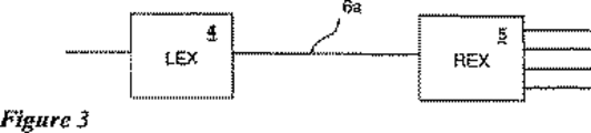
図3はUTP以上で操作するよう設計された本発明による実施形態を表している。この実施形態では、非遮蔽ツイステッドペア(Unshielded Twisted Pair)(UTP)長さの銅線(6a)で接続された2つの分割ユニットにより、USBハブで提供される通常の機能が提供されている。ホストPCをローカル伸張器(LEX)と称する第1ユニット(4)に接続してもよい。ここでは第2ユニット(6)をリモート伸張器(REX)と称する。REX(6)は複数のUSB装置に接続してもよい。本実施形態では、複数機として四機を選んだが、発明の範囲内で別の選択がなされることは当業者に明らかである。
【0062】
前記LEXユニット(4)を前記ホストPCに接近させ、前記REXユニット(5)を前記複数のUSB装置に接近させ、さらに所望のUTP長さを超えたケーブル(6a)によりLEXユニット(4)とREXユニット(5)とを接続して、拡大距離以上の操作が完全に達成されている。
【0063】
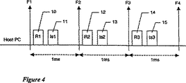
図4はUSBプロトコルによる等時性送信を表す時間経過を示している。図は、USBホストコントローラーの観点から構成され、通常PCマザーボード(ホストPC)上に含まれる。USBプロトコルは共有バスに付加される時間を所要時間の1msごとに定期的なフレーム(frame)に分割する。各フレームのスタートは図1、図2、図3、図4に代表されている。ホストコントローラーが等時性送信上で装置と接続されているときに、ホストコントローラーは前記装置にデータ送信の定期的要求を発生する。これらの要求は図4にパケットR1、R2、R3、(10、12、14)として代表されている。USBプロトコルのもとでは、USB装置は16ビットタイム内で前記要求に応答する必要がある。一般に、送信ls1(11)は要求R1(10)への応答に伝達され、送信ls2(13)は要求R2(12)への応答に伝達され要求が終了するまで続くものと考えられる。
【0064】
図5は本発明による等時性送信を表す時間経過図を提供している。図は本発明を構成する様々なサブシステムを通じてパケットの前進を示している。タイムラインは図2に表されたホストPC(1)、ローカル伸張器(LEX)(4)、リモート伸張器(REX)(5)の各構成要素に対して提示されている。
【0065】
等時性送信は、特殊なUSBアドレスとエンドポイントに出力データR1(20)用の要求を放つことで、ホストPC(1)から開始される。前記要求R1(20)はLEX(4)に受付けられREX(5)までの外部ケーブルからR1(25)として再送信される。前記再送信されたパケットR1(25)はREX(5)に受付けられ目的の装置(一例として図2の符号3a、3b、3c、3dの1つ)までR1(31)として送られる。
【0066】
目的の装置は出力データパケットls1(32)を発生する。USBプロトコルによれば、集積されたケーブルのない装置は対応する要求の終了の6.5ビットタイム以内に応答を発生する必要がある。前記出力データパケットls1(32)はREXサブシステム(5)によりうけつけられ、外部電線からLEX(4)までls1(26)として再送信される。前記再送信された応答ls1(26)は即座にホストPC(1)に伝送されず、LEXサブシステム(4)のメモリー内に蓄積されている。
【0067】
ホストPC(1)はその出力データ要求R1(20)に、応答を受付けていないことを知らせ、同じUSBアドレスとエンドポイントに新規な要求R2(21)を発生することで、伝送を再び試みる。要求R2(21)を受付けると、LEXサブシステム4はメモリバッファから応答ls1(26)を回収して、応答ls1(22)としてホストPCに伝送する。
【0068】
前記第2要求R2(21)はLEXを通してR2(27)として繰り返され、装置にR2(33)として送られる。目的の装置はREXによりls2(28)として再送信される第2の応答ls2(34)をLEXに発生する。応答ls2(28)は再びLEXサブシステムのメモリー内に蓄積されここから第3要求R3(23)に対する応答ls2(24)としてホストPC(1)に送られる。必要に応じてプロセスは要求R3(23)、R3(29)、R3(35)と応答ls3(36)、ls3(30)と共に繰り返される。
【0069】
図6は本発明によるローカル伸張器(LEX)(4)の一実施形態を示している。前記実施形態は四つの主なブロックからなる。USBインターフェース(50)はホストPCを標準USBケーブルを使用するユニットに接続させる。前記USBインターフェース(50)は前記ホストPCから、USBフォーマットに信号を受付け、LEXコントローラー(51)にUSBパケットを伝送する。前記LEXコントローラー(51)は受付けたパケットにどの応答が必要かを決定し、適宜USBパケットを発生する。前記LEXコントローラー(51)が送信前に蓄積された情報を必要とする場合は、前記情報はRAM(53)に蓄積される。
【0070】
リモート伸張器(REX)(5)に伝送される必要がある情報は、UTPインターフェース(52)に送られここで、情報は銅線の伝搬に適したデジタル信号に変換される。
【0071】
反対方向では、リモート伸張器(5)から起こったデジタル信号がUTPインターフェース(52)に受付けられ、LEXコントローラー(51)に送られる。前記LEXコントローラー(51)はRAM(53)にどの必要な情報も蓄積し、要求された応答を発生する。ホストPCに送られる必要がある情報はUSBインターフェース(50)に送信され、ここから標準USBハードウェア並びにプロトコルを使用する前記ホストPCに送られる。
【0072】
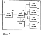
図7は本発明によるリモート伸張器(REX)(5)の実施形態を表している。前記実施形態はUTPインターフェース(60)と、複数のUSBインターフェース(63、64、65、66)と、REXコントローラー(61)とRAM(62)とからなる。REX(5)の操作はLEX(4)のそれと同様である。
【0073】
図8は本発明による等時性入力送信の順序を示す図である。図に使用されるフォーマットはヤコブソン等に起因するものである(イワンヤコブソン、マグナスクリスターソン、パトリックジョンソン、グンナーオーヴァー監視、オブジェクトオリエンテッドソフトウェアエンジニアリング:ア ユース ケース ドリブン アプローチ、アディッソン ウェズレイ、1992年)。
【0074】
フレーム1ではホストPC内のコントロール(制御)ロジック(論理)(100)が特殊なUSB機能に向けて入力データに対する要求を発生する。前記要求はインアドレス(In Addr)パケットとしてLEXサブシステムに送信される。LEXサブシステム内のコントロールロジック(101)はREXサブシステムにインアドレスパケットを伝送する。REXサブシステム内のコントロールロジック(102)は装置にインアドレスパケットを伝送する。
【0075】
装置内のコントロールロジック(103)は要求された等時性データを組み付けこれをデータペイロードパケットとしてREXサブシステムに送信する。REXサブシステム内のコントロールロジック(102)はLEXサブシステムにデータペイロードパケットを伝送する。LEXサブシステム内のコントロールロジック(101)はそのバッファメモリにデータペイロードパケットを蓄積する。
【0076】
フレーム2では、ホストPC内のコントロールロジック(104)が入力データ用の先の要求に応答を受付けていないことを理解する。前記コントロールロジックは、フレーム1と同様のUSB機能に対して別の要求を発生することにより、実績(処理)(transaction)を再び試みる。前記別の要求は第二のインアドレスパケットとしてLEXサブシステムに送信される。第二インアドレスパケットを受付けると、LEXサブシステム内のコントロールロジック(105)が、別のインアドレスパケットに代表される同じ機能から、メモリー内に蓄積されたデータペイロードパケットを得たことを理解する。前記コントロールロジック(105)は前記蓄積パケットを回収し、これをホストPCに送信する。前記コントロールロジック(105)はまたREXサブシステムに新規インアドレスパケットを伝送する。REXサブシステム内のコントロールロジック(106)は装置にインアドレスパケットを伝送する。
【0077】
装置内のコントロールロジック(107)が要求された等時性データを組立これをデータペイロードパケットとしてREXサブシステムに送信する。REXサブシステム内のコントロールロジック(106)がLEXサブシステムにデータペイロードパケットを伝送する。LEXサブシステム内のコントロールロジック(105)はそのバッファメモリにデータペイロードパケットを蓄積する。
【0078】
上述のプロセスが、分布されたコントロールロジック(一例として、108、109、110、111)により連続するフレームに対して繰り返される。
【0079】
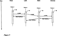
図9では、本発明による別の等時性入力送信の順序図が提供されている。図8に説明した方法と異なり、等時性入力送信に対する第一の要求を扱う方法方である。
【0080】
フレーム1では、ホストPC内のコントロールロジック(100)が特殊なUSB機能に対して入力データ用の要求を発生する。前記要求はインアドレスパケットとしてLEXサブシステムに送信される。LEXサブシステム内のコントロールロジック(101)は図8のREXサブシステムにインアドレスパケットを伝送する。
【0081】
順序のこの時点で、別の工程が導入されている。LEXサブシステム内の前記コントロールロジック(101)は合成データパケットを発生し、これをホストPCにデータペイロードパケットとして送信する。前記合成データパケットは図9ではデータペイロード 0とされている。プロトコル取り扱いの残る部分は図8に記載されたごとく続く。
【0082】
USB仕様書は単体バイトパケット識別子(PID)と、0バイトから1023バイトサイズ範囲のデータペイロードと、2バイトのサイクル冗長量チェックとからなるデータパケットをなしている。前記合成データパケットは従ってゼロ長さペイロードを含むデータパケットを組み立てることにより構成されうる。前記合成データパケットはこれにより、プロトコルにより伝搬される実際の情報を侵害することなく、USBプロトコルのタイミング要求を満足するために利用され得る。
【0083】
図10は本発明による等時性出力送信の順序図を示している。
【0084】
フレーム1において、ホストPC内のコントロールロジック(120)は特殊なUSB機能に向けて出力データの通知を発生する。前記通知はアウトアドレスパケットとしてLEXサブシステムに送信される。LEXサブシステム内のコントロールロジック(121)はREXサブシステムに前記アウトアドレスパケットを伝送する。REXサブシステム内のコントロールロジック(122)は装置に前記アウトアドレスパケットを伝送する。情報は装置内のコントロールロジック(123)により受付けられる。
【0085】
ホストPC内のコントロールロジック(120)は通知された等時性データを組み立て、データペイロードパケットとしてLEXサブシステムに送信する。LEXサブシステム内のコントロールロジック(121)はREXサブシステムにデータペイロードパケットを伝送する。 LEXサブシステム内のコントロールロジック(122)が装置にデータペイロードパケットを伝送する。情報は装置内のコントロールロジック(123)により受信される。
【0086】
図11はローカル伸張器(4)で等時性送信を実現するアルゴリズムを示している。図6で説明した本発明による実施形態において、前記アルゴリズムはLEXコントローラー(51)によりハードウェア内部で実現されている。(当業者にとって、この実現は特別なものではなく前記アルゴリズムを実現する別のメカニズムが可能であることは明白である)。以下、周辺機器からホストコントローラーまで移動するパケットの上り方向とホストコントローラーから周辺機器までを移動するパケットの下り方向を説明する。
【0087】
本発明によれば、図8の工程ブロック(101、105、109)と図10の工程ブロック(121)に代表される工程機能を実現するには図11のアルゴリズムが必要である。
【0088】
初期立ち上げやリセットのあとには、システムはアイドル状態(200)になり、メッセージ(USBパケット)の受信を待機している。パケットが受信されると、パケット内部のパケット識別子(PID)分野が試験され、どのタイプのパケットが受信されたか、前記パケットをプロセスするにはどのアクションが必要かを決定する。
【0089】
受信したパケット(201)がタイプINの場合、同一のパケット(202)が送信される。そこでシステムはそのバッファメモリを試験し(203)、IN要求が向けた装置からの蓄積データパケットが既にメモリに存在するか否かを決定する。この蓄積データパケットがメモリに存在しない場合、システムはさらにアイドル状態(200)に戻る。蓄積データパケットがメモリ内に存在する場合は、システムはメモリから蓄積したパケットを回復(204)、データタイプのパケットとしてホストに前記パケットを送る(205)。システムはここでアイドル状態(200)に戻る。
【0090】
受信したパケット(206)がデータタイプで上り方向に移動していると、システムはバッファメモリにデータパケットを保管する(207)。システムはここでアイドル状態(200)に戻る。
【0091】
受信したパケット(208)がアウトアドレスタイプの場合、システムはパケットを再度送信し(209)、アイドル状態(200)に戻る。
【0092】
受信したパケット(210)がデータタイプで下り方向に移動していると、システムはパケットを再度送信し(211)、アイドル状態(200)に戻る。
【0093】
図12は図9に説明した本発明によるローカル伸張器における等時性送信を実現する強化アルゴリズムを示している。このアルゴリズムは、本質的には図11に説明したものと同様であるが、異なる点は、ホストがデータ要求を発生し、LEXがホストに戻す前記データをまだ抱えていない状態を扱っていることである。この状態は等時性の入力セッションの第一の要求に起こる。
【0094】
図12において、受信したパケット(201)がタイプINの場合、同一のパケット(202)が送信される。そこでシステムはそのバッファメモリを試験し(203)、IN要求が目指した装置からの蓄積データパケットが既にメモリに存在するか否かを決定する。この蓄積データパケットがメモリに存在しない場合、システムは合成データパケットを発生し(212)、発生したパケットをUSBプロトコルに許可された16ビットタイム内でホストに送信する。蓄積データパケットがメモリ内に存在する場合は、システムはメモリから蓄積したパケットを回復(204)、データタイプのパケットとしてホストに前記パケットを送り(205)、システムはここでアイドル状態(200)に戻る。
【0095】
受信したパケット(206)がデータタイプで上り方向に移動していると、システムはバッファメモリにデータパケットを保管する(207)。新規蓄積パケットを伴うパケット経時(Aging)フラッグが図13で説明する理由によりリセットされる(214)。システムはここでアイドル状態(200)に戻る。
【0096】
図13は残留パケットを取り除き可能にするLEXコントローラーをさらに強化する論理図である。ホストPCがセッションの終結を決定するが、LEXコントローラーが既に前記セッションに属する上りデータパケットを所有しているときに、等時性入力送信の間、前記残留パケットが起こり得る。この状態は一例としてパケットデータペイロード 3として図8に示される。
【0097】
USB仕様書のもとでは、各フレームのスタートは独特のスタートオフフレーム(SOF)信号でマークされる。図13に説明される実施形態は、もはや要求されていないパケットを識別し放棄するためにこのSOF信号を利用している。SOF信号(221)がローカル伸張器に受信されるとプロセスが開始する。ローカルバッファメモリの検索は第一バッファ(222)に前後関係をセットすることで開始される。現状の関係により指摘されたパケットのパケット経時フラッグがテストされる(223)。パケット経時フラッグが既にセットされると、バッファ内のパケットが放棄される(224)。パケット経時フラッグがセットされていないと、パケット経時フラッグは、パケットがこのときまで送信されていない場合は、次のフレームで確実に放棄されるようセットされる(225)。
【0098】
次のバッファに関係をセット(227)し、テストして検出されるように(228)、全てのバッファがチェックされるまで続けることにより前記プロセスが繰り返される。
【0099】
残留パケットの早期放棄を防ぐために別の予防措置として、LEXコントローラーのバッファメモリ内にデータパケットが蓄積される場合は常に図12の工程(214)によりパケット経時フラッグがまたリセットされる。
【0100】
図14はリモート伸張器での等時性送信の実現アルゴリズムを示す。図7に説明した本発明の実施形態において、前記アルゴリズムはREXコントローラー(61)によりハードウェア内部で実現される(この実現は特異なものではなく前記アルゴリズムを実現する別のメカニズムも可能であることは当業者にとって明らかである)。以下の説明では、周辺機器からホストコントローラーまで移動するパケットの上り方向と、ホストコントローラーから周辺機器までを移動するパケットの下り方向を説明する。
【0101】
本発明によれば、図8のプロセスブロック(102)、(106)、(110)と、図10のプロセスブロック(122)とに代表されるプロセス機能を実現するには図14のアルゴリズムが要求される。
【0102】
初期立ち上げやリセットのあとには、システムはアイドル状態(230)になり、メッセージ(USBパケット)の受信を待機している。パケットが受信されると、パケット内部のパケット識別子(PID)分野が試験され、どのタイプのパケットが受信されたか、前記パケットをプロセスするにはどのアクションが必要かを決定する。
【0103】
受信したパケット(231)がINタイプであると、システムは前記INパケットを再送信しアイドル状態に戻る(230)。
【0104】
受信したパケット(233)がデータタイプで上り方向に移動すると、システムは前記データパケットを再送信しアイドル状態に戻る(230)。
【0105】
受信パケット(235)がタイプOUTであるときは、システムは前記OUTパケットを再送信(238)して待機状態(230)に戻る。
【0106】
受信パケット(235)がタイプDATAであって且つアウト方向に流れているときは、システムは前記DATAパケットを再送信(238)して待機状態(230)に戻る。
【0107】
図15は、リモート伸張器における等時性転送実行のための強化アルゴリズムを備えている。一定条件の下では、リモート伸張器から送られローカル伸張器に到着しているパケットが、ローカル伸張器の期待する順序になっていない危険性がある。図15に記述する強化によりイン方向に送られるパケットにアドレスフィールドを追加し、ローカル伸張器が前記パケットの発生源を確認出来るようにする。
【0108】
強化により、REXコントローラがINパケットを受信すると、それに含まれるアドレスがメモリ(239)に記憶される。次いでINパケットを、前のように再送信(232)して、システムは待機状態(230)に戻る。イン方向に動いている次のDATAパケットをシステムが受信する(233)と、システムはメモリ(240)内に記憶されたアドレスを回復して、LEXに再送信(234)するDATAパケットにこの情報を含める。システムは待機状態(230)に戻る。
【0109】
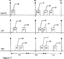
図16は、USBプロトコルにしたがう非同期転送を示すタイミングダイヤグラムを与える。このダイヤグラムは、PC(ホストPC)マザーボードに通常含まれるUSBホストコントローラの観点から作られている。USBコントローラは共有バス上の時間割当を、各々の継続時間が1msの、規則的フレームに分割する。各フレームのスタートは、ここでも図上でF1、F2、F3及びF4として識別される。
【0110】
ホストコントローラが非同期転送に際し周辺装置と話中になると、ホストコントローラは、必要に応じてのベースで、前記周辺装置にデータ送信要求を発行する。これらの要求は、図4でパケットR1及びR2(10及び12)として識別される。USBプロトコルの下では、USB周辺装置は前記要求に16ビット時間以内に応答しなければならない。応答をA1及びA2(11及び13)として示す。移送A1(11)は要求R1(10)応じておこなわれ、移送A2(13)は要求R2(12)応じておこなわれ、以下同様に、要求が終わるまで続くことが通常期待される。
【0111】
図17は、本発明にしたがう非同期転送を示すタイミングダイヤグラムを与える。このダイヤグラムは、本発明に含まれる各種サブシステムを通るパケットの進行状況を示す。図2に示したホストPC(1)、ローカル伸張器(4)及びリモート伸張器(5)サブシステムについて、時間線を示す。
【0112】
非同期転送は、ホストPC(1)から、データR1入力要求(20A)を特定のUSBアドレス及びエンドポイントに対し出すことによりはじまる。前記要求R1(20A)をLEX(4)が受信し、外部ケーブルを通じてREX(5)に対しR1(24A)として再送信する。前記再送信パケットR1(24A)は、REX(5)が受信し、目標周辺装置(即ち、3a、3b、3c及び3dのうち一つ)に対しR1(29A)として送られる。
【0113】
目標周辺装置は、入力データパケットA1(30A)を作成する。USBプロトコルにしたがって、統合ケーブルなしの周辺装置は、対応する要求の終わりから6.5ビット時間以内に応答を作成しなければならない。前記入力データパケットA1(30A)は、REXサブシステム(5)が受信し、A1(24A)として外部配線を通じてLEX(4)に対し再送信される。前記再送信応答A1(25A)は、直ちにはホストPC(1)に送られないで、LEXサブシステム(4)のメモリ内に記憶される。
【0114】
ホストPC(1)は、そのデータ入力要求R1(10A)に対する応答を受信しなかったことを通告し、同一USBアドレス及びエンドポイントに対して新規要求R2(21A)を作成して処理を再試行する。要求R2(26A)を受信すると、LEXサブシステム(4)は応答A1(25A)をそのメモリバッファから回復し、それを応答A1(27A)としてホストPCに対して送る。前記応答(27A)は、応答A1(22A)としてホストPCが受信する。
【0115】
前記第二要求R2(21A)は、R2(26A)としてLEXを通じて繰り返され、R2(31A)として周辺装置に送られる。目標周辺装置は、単にREXサブシステム(3)が吸収するだけの第二応答A2(32A)を作成する。ホストが前記応答A1(22A)を受信すると、これは受信通知K1(23A)を作成し、それをLEXサブシステム(4)に送信する。前記受信通知K1(23A)は、受信通知K1(28A)としてLEXが受信しREXに送られる。そこには受信通知K1(33A)として現れる。受信通知K1(33A)が再びUSB周辺装置に送られて、プロトコルシーケンスが完了する。
【0116】
図18は、本発明にしたがう非同期入力転送を示すシーケンスダイアグラムを与える。
【0117】
フレーム1において、ホストPC内のコントロールロジック(130)が、特定のUSB機能に宛てたデータ入力の要求を作成する。前記要求は、LEXサブシステムに「InAddr」パケットとして送信される。LEXサブシステム内のコントロールロジック(131)が、このInAddrパケットをREXサブシステムに対して送る。REXサブシステム内のコントロールロジック(132)が、このInAddrパケットを周辺装置に対して送る。周辺装置内のコントロールロジック(133)が、要求された非同期データを組み立てて、それを「DATAPayload」パケットとしてREXサブシステムに対して送る。REXサブシステム内のコントロールロジック(132)が、このDATAPayloadパケットをLEXサブシステムに対して送る。LEXサブシステム内のコントロールロジック(131)は、このDATAPayloadパケットを、そのバッファメモリ内に記憶する。
【0118】
フレーム2において、ホストPC内のコントロールロジック(134)が、データ入力についての前の要求に対する応答を受け取っていないことを認識する。前記コントロールロジックは、フレーム1と同一のUSB機能宛に追加要求を作成して、自動的に処理を再試行する。前記追加要求は、LEXサブシステムに対し第二InAddrパケットとして送信される。この第二InAddrパケットを受信すると、LEXサブシステム内のコントロールロジック(135)は、追加InAddrパケットが指定するのと同一機能からメモリに記憶されたDATAPayloadパケットを有することを認識する。前記コントロールロジックは、前記記憶パケットをメモリから回復して、それをホストPCに対して送信する。前記コントロールロジック(135)はまた、新規InAAddrパケットをREXサブシステムに対して送る。REXサブシステム内のコントロールロジック(136)が、このInAddrパケットを周辺装置に対して送る。
【0119】
周辺装置内のコントロールロジック(137)は、前の送信に対して受信通知を受け取っていないことを認識して、この新規要求が実際は元の情報に関する二番目の要求であると推定する。これにより周辺装置は、要求された非同期データを組み立てて、それをDATAPayloadパケットとしてREXサブシステムに送る。REXサブシステム内のコントロールロジック(138)は、このDATAPayloadパケットが、前の送信の単なる繰り返しであることを認識して前記パケットを吸収する。
【0120】
ホストのコントロールロジック(134)が、要求されたDATAPayloadパケットをLEXから受信すると、前記コントロールロジックは、Ackパケットを作成して、送信成功を通知する。前記Ackパケットは、LEX内のコントロールロジック(135)が受信し、REXに対して送る。前記送られたAckパケットは、REX内のコントロールロジック(136)が受信し、さらに周辺装置に対して送られる。REXから周辺装置に対するAckパケットの送信は、繰り返されたDATAPayloadパケットの周辺装置からの送信終わりに続く必要応答期間内に起こるよう、コントロールロジック(136)が同期する。
【0121】
図19は、本発明にしたがう非同期入力転送代替案を示すシーケンスダイアグラムを与える。この方法は、図18に記述したものに対し、非同期入力転送に関する最初の要求をLEXが扱う方法が異なる。
【0122】
フレーム1において、ホストPC内のコントロールロジック(130)が、特定のUSB機能に宛てたデータ入力の要求を作成する。前記要求は、LEXサブシステムに対しInAddrパケットとして送信される。LEXサブシステム内のコントロールロジック(131)が、図18に記述したように、このInAddrパケットをREXサブシステムに対して送る。
【0123】
シーケンスのこの時点で、追加のステップが導入される。前記LEXサブシステム内のコントロールロジック(131)が、合成否定的受信通知パケットを作成し、それをNakパケットとしてホストPCに対して送る。前記Nakパケットはホストに、その要求に対する応答を受け取らないことを警告し、前記ホストが次の処理に進むことが出来ないようにする。プロトコル取扱の残余部分は、図18に記述するように継続する。
【0124】
図20は、本発明にしたがう非同期出力転送を示すシーケンスダイアグラムを与える。
【0125】
フレーム1において、ホストPC内のコントロールロジック(140)が、特定のUSB機能に宛てたデータ出力の通知を作成する。前記通知は、LEXサブシステムに対しOUTAddrパケットとして送信される。LEXサブシステム内のコントロールロジック(142)が、前記OUTAddrパケットをREXサブシステムに対して送る。REXサブシステム内のコントロールロジック(142)が、前記OUTAddrパケットを周辺装置に対して送る。情報は、周辺装置内のコントロールロジック(143)が、受信する。
【0126】
ホストPCサブシステム内のコントロールロジック(142)は、通知された非同期データを組み立てて、それをDATA PayloadパケットとしてLEXサブシステムに送る。LEXサブシステム内のコントロールロジック(142)は、このDATA PayloadパケットをREXサブシステムに送る。LEXサブシステム内のコントロールロジック(141)は、このDATA Payloadパケットをさらに周辺装置に送る。情報は周辺装置内のコントロールロジック(143)が受信する。
【0127】
周辺装置が、前記DATAPayloadパケットを無事受信すると、周辺装置内のコントロールロジック(143)が、受信通知を作成し、これをAckパケットとしてREXに対して送る。前記Ackパケットは、REX内のコントロールロジック(142)によりLEXサブシステムに対して送られ、その受信がコントロールロジック(141)により記録される。
【0128】
フレーム2において、ホストPC内のコントロールロジック(144)が、前の送信に対する応答を受け取っていないことを認識し、フレーム1と同一のアドレスとエンドポイントに宛てて新規OUTAddrパケットを作成する。同一コントロールロジック(144)がまた、新規DATAPayloadパケットを作成し、これをLEXに対して送信する。LEXがこのDATAPayloadパケットを受信すると、コントロールロジック(145)が、この処理の肯定的受信通知を既に有していることを認識して、Ackパケットを作成し、それをホストに対して送る。
【0129】
図21は、本発明にしたがう強化非同期出力転送を示すシーケンスダイアグラムを与える。この方法は、図20に記述したものに対し、非同期出力転送に関する最初の要求をLEXが扱う方法が異なる。
【0130】
フレーム1において、ホストPC内のコントロールロジック(140)が、特定のUSB機能に宛てたデータ出力の通知を作成する。前記要求は、LEXサブシステムにOUTAddrパケットとして送信される。LEXサブシステム内のコントロールロジック(141)が、図20に記述したように、このOUTAddrパケットをREXサブシステムに対して送る。
【0131】
フレーム1においてはまた、ホストPC内のコントロールロジック(140)が、前記特定のUSB機能宛のOUTput DATAパケットを作成する。前記OUTput DATAパケットは、LEXサブシステムに対しDATAPayloadパケットとして送信される。LEXサブシステム内のコントロールロジック(141)が、図20に記述したように、このDATAPayloadパケットをREXサブシステムに対して送る。
【0132】
シーケンスのこの時点で、追加のステップが導入される。前記LEXサブシステム内のコントロールロジック(141)が、合成否定的受信通知パケットを作成し、それをNakパケットとしてホストPCに送る。前記Nakパケットはホストに、その送信に対する応答を受け取らないことを警告し、前記ホストが次の処理に進むことが出来ないようにする。プロトコル取扱の残余部分は、図20に記述するように継続する。
【0133】
図22は、ローカル伸張器(4)において非同期転送を実行するためのアルゴリズムを与える。図6に示した本発明の実施例において、前記アルゴリズムはLEXコントローラ(51)によりハードウエア内で実行された。(この実行は唯一ではなく、前記アルゴリズム実行のために、別の機構が可能であることは当業者に明らかであろう。)以下の記述において、イン方向とは、周辺装置からホストコントローラに向けて移動するパケットを指し、アウト方向とは、ホストコントローラから周辺装置に向けて移動するパケットを指す。
【0134】
本発明にしたがうと、図22のアルゴリズムは、図18の処理ブロック(131)と(135)、及び図20の処理ブロック(141)と(145)があらわす処理機能を、実行するのに必要である。
【0135】
最初の電源投入に際し及びリセットの後に、システムは待機状態(300)に入り、そこでメッセージ(USBパケット)受信を待つ。パケットを受信すると、パケット内のパケット識別子(PID)フィールドを点検して、受信したパケットの型及びそのパケット処理に必要な処置を判定する。
【0136】
受信パケット(301)が、INタイプであるとき、システムは、前記INパケットをREXユニットに対して再送信する。システムは次いで、そのバッファメモリ(303)を検査して、そのINパケットと同じアドレスからのイン方向DATAパケットが利用出来るか否かを判定する。前記DATAパケットが利用出来るときは、それをバッファメモリから回復して、ホストに対し送信(305)する。システムは待機状態(300)に戻る。
【0137】
受信パケット(306)が、DATAタイプのものであり且つイン方向に動いているとき、システムは、前記DATAパケットをバッファメモリにセーブ(307)して待機状態(300)に戻る。
【0138】
受信パケット(308)が、ACKタイプのものであり且つイン方向に動いているときは、システムは、前記ACKパケットを再送信(309)して待機状態(300)に戻る。
【0139】
受信パケット(310)が、OUTタイプのものであるとき、システムは、そのアドレスに関するOUT保留フラグが設定されているか否かを点検(311)する。前記フラグが設定されているとき、システムは、前記フラグをリセットして待機状態(300)に戻る。前記フラグが設定されていないとき、システムは、待機状態(300)に戻る前に、前記フラグを設定(312)して前記受信OUTパケットを再送信(313)する。
【0140】
受信パケット(315)が、DATAタイプのものであり且つイン方向に動いているとき、システムは、そのアドレスに関するDATA保留フラグが設定されているか否かを検査(316)する。前記フラグが設定されていないとき、システムは、待機状態(300)に戻る前に、前記フラグを設定(323)して前記受信DATAパケットを再送信(324)する。前記DATA保留フラグが設定されているとき、システムは、前記DATA保留フラグをリセット(317)して、そのアドレスに関するACKパケットがバッファメモリに記憶されているか否かを検査する。前記ACKパケットがメモリ内に存在するとき、システムは、前記パケットをメモリから回復(319)して、前記パケットをホストに対し送信(320)する。システムは待機状態(300)に戻る。
【0141】
受信パケット(321)が、ACKタイプのもので且つイン方向に動いているとき、システムは、前記ACKパケットをバッファメモリにセーブ(322)して待機状態(300)に戻る。
【0142】
図23は、図6に記述した本発明にしたがうローカル伸張器において、非同期転送おこなうための強化アルゴリズムを与える。このアルゴリズムは、LEXがホストに対しそのコマンドに対する応答が得られないことを通知すること以外は、図22に記述したものと同一である。この状況は、図19及び21に記述したデータ転送シーケンスを、ホストが初動したとき起こる。
【0143】
追加ステップ(331)は、システムがINパケットを受け取ったけれども、要求されたデータはバッファメモリに記憶していないとき、起こる。システムは、待機状態(300)に戻る前に、否定的受信通知パケットをホストに送る(331)。
【0144】
追加ステップ(332)は、システムがアウト方向に動くDATAパケットを受け取ったけれども、DATA保留フラグが設定されていないとき、起こる。システムは、待機状態(300)に戻る前に、否定的受信通知パケットをホストに送る(332)。
【0145】
図24は、リモート伸張器において、非同期転送おこなうための強化アルゴリズムを与える。図7に記述した本発明の実施例において、前記アルゴリズムは、REXコントローラ(61)によりハードウエア内で実行される。(この実行は唯一ではなく、前記アルゴリズムを実行するために別の機構が可能であることは当業者に明らかであろう。)以下の記述において、イン方向とは、周辺装置からホストコントローラに向けて移動するパケットを指し、アウト方向とは、ホストコントローラから周辺装置に向けて移動するパケットを指す。
【0146】
本発明にしたがうと、図22のアルゴリズムは、図18の処理ブロック(132)と(138)、及び図20の処理ブロック(142)があらわす処理機能を実行するのに必要である。
【0147】
最初の電源投入に際し及びリセットの後に、システムは待機状態(340)に入り、メッセージ(USBパケット)受信を待つ。パケットを受信すると、パケット内のパケット識別子(PID)フィールドを点検して、受信したパケットの型及びそのパケットの処理に必要な措置を判定する。
【0148】
受信パケット(341)がINタイプのものであるとき、システムは、前記INパケットを再送信(342)して、待機状態(340)に戻る。
【0149】
受信パケット(343)が、DATAタイプのものであって且つイン方向に動いているとき、システムは、そのアドレスに関するデータ保留フラグが設定されているか否かを点検(345)する。前記フラグが設定されているとき、システムは、待機状態(340)に戻る前に、前記フラグを設定(346)し、前記受信DATAパケットをLEXに対し再送信(347)する。
【0150】
受信パケット(348)が、ACKタイプのものであって且つアウト方向に動いているとき、システムは、前記ACKパケットを再送信(349)して、待機状態(300)に戻る。
【0151】
受信パケット(350)がOUTタイプのものであるとき、システムは、前記OUTパケットを再送信(351)して待機状態(340)に戻る。
【0152】
受信パケット(352)が、DATAタイプのものであって且つアウト方向に動いているとき、システムは、前記DATAパケットを再送信(353)して待機状態(340)に戻る。
【0153】
受信パケット(353)が、ACKタイプのものであって且つイン方向に動いているとき、システムは、前記ACKパケットを再送信(355)して、待機状態(340)に戻る。
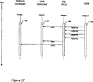
【0154】
図25は、図7の本発明にしたがうREXコントローラ(61)実施例を図示する。この実施例において、REXの制御機能は、二つの別々の部品、ネットワークコントローラ(403)とリンクコントローラ(401)、に分割される。先入れ先出し(FIFO)バッファ(400)と(402)を用いて、個々のパケットを、USBインターフェイス(63)がそれらを送受したままの状態で保持する。
【0155】
別々のコントローラ(403)と(401)への機能分割により、システムの作動を簡単に記述することが可能となる。ネットワークコントローラ(403)が、図24に示すようなネットワークレイヤ機能を果たす一方で、リンクコントローラ(401)は、個々のパケット送受信に伴うリンクレイヤ機能を果たす。
【0156】
図25の部品間で、以下の信号が作られる。
【0157】
ネットワークコントローラ(403)は、信号ISOを発生して、自分がTXFIFO(403)に置いたパケットは同時送信関連なので受信通知は期待しないことを通知する。
【0158】
TXFIFO(403)は、信号TXRDYを発生して、自分が送信準備完了の完全パケットを含んでいることを通知する。TXFIFO(403)はまた、信号TXVORを発生して、USBインターフェイス(63)へのパケット送信を完了したことを通知する。
【0159】
RXFIFO(400)は、信号SOPを発生して、USBインターフェイス(63)からパケット受信を開始したことを通知する。RXFIFO(400)はまた、信号EOPを発生して、USBインターフェイス(63)からのパケット受信を完了したことを通知する。リンクコントローラ(401)は、信号TXNEBを発生して、その情報をUSBインターフェイス(63)に送るためTXFIFOをクリヤしたことを、TXFIFO(402)に対し通知する。
【0160】
図26は、リンクレーヤパケット出力を示すシーケンスダイアグラムを与える。この図において、コントロールロジック(410)は、ネットワークコントローラ(403)が実行し、コントロールロジック(411)は、リンクコントローラ(401)が実行し、コントロールロジック(412)は、TXFIFO(402)が実行し、コントロールロジック(413)はUSBインターフェイス(63)が実行する。
【0161】
リンクレイヤ出力シーケンスは、ネットワークコントローラ(403)がデータバケットをTXFIFO(402)に結合しWRITE信号を立ち上げたとき開始される。前記ネットワークコントローラ(403)はまた、信号ISOを用いて、前記パケットが等時性交信を運んでいるか否かを、リンクコントローラ(401)に対し通知する。TXFIFO(402)が前記データパケットを完全に受信すると、前記TXFIFOは信号TXRDYを立ち上げて、リンクコントローラ(401)に対し、データパケットをUSBインターフェイス(63)に出力する準備が整ったことを通知する。
【0162】
リンクコントローラ(401)が、USBインターフェイス(63)にアクセスするのに何の競合もないと、判断すると、前記リンクコントローラ(401)は、信号TXENBを立ち上げて、前記USBインターフェイス(63)に対する前記データパケットの送信を今開始してよいことを、TXFIFO(402)に対し通知する。そこでTXFIFO(402)は、前記データパケットをUSBインターフェイス(63)に対し、一度に一バイト宛、信号TXBYTEを用いて送信する。
【0163】
前記データパケット内のバイト全部を送信すると、TXFIFO(402)は、信号TXOVRを立ち上げて、送信を完了したのでUSB関連の別の仕事を計画することが出来ることを、リンクコントローラ(401)に対し通知する。リンクコントローラ(401)は、信号TXENBを下げることにより握手を完了し、追加データパケットが前記リンクコントローラによる妨害を受けることなく送信されるのを防止する。
【0164】
図27は、リンクレーヤパケット入力を示すシーケンスダイアグラムを与える。この図において、コントロールロジック(420)は、ネットワークコントローラ(403)が実行し、コントロールロジック(421)は、リンクコントローラ(421)が実行し、コントロールロジック(422)は、RXFIFO(422)が実行し、コントロールロジック(423)は、USBインターフェイス(63)が実行する。
【0165】
リンクレイヤ入力シーケンスは、RXFIFO(400)が、信号RXBYTEを用いて、新規データパケットの最初のバイトをUSBインターフェイス(63)から受信したとき開始される。このとき、前記RXFIFOは、信号SOPを用いて、新規パケットの開始が検出されたことを、リンクコントローラ(401)に対し通知する。次いで、RXFIFO(400)が、追加RXBYTE信号を用いて、このデータパケットの残りを受信する。
【0166】
RXFIFO(400)が完全なデータパケットを受信し終えると、リンクコントローラ(401)に対し、パケット終了信号EOPを用いて通知する。次いで、RXFIFO(400)は、信号READを用いて、完全なパケットをネットワークコントローラ(403)に転送する。
【0167】
図28は、図25の本発明にしたがうリンク制御機能実行のためのアルゴリズムを与える。図25の実施例において、図28のリンク制御機能は、別個のリンクコントローラブロック(401)を用いて実行される。
【0168】
最初の電源投入に際し及びリセットの後、システムは待機状態(470)に入り、そこで信号受信を待つ。
【0169】
受信信号(471)がTXRDYであるとき、システムは、監視フラグが設定されているか否かを検査(472)する。前記監視が設定されているとき、システムは待機状態(470)に戻る。前記監視が設定されていないとき、システムは前記フラグを設定(473)して、システムに別のパケットを送信する準備が整っていないことを知らせる。システムは次いで、ISO信号を検査(474)し、送信されるパケットが等時性送信をあらわすか否かを判定する。前記ISO信号が真であるときは、監視タイマーを2ビット−タイムに設定(475)する。前記ISO信号が偽であるときは、監視タイマーを16ビット−タイムに設定する。システムは、次いで、信号TXENBを設定(477)してUSBインターフェイス(63)に対するパケット送信を開始することが出来ることを知らせて、送信状態(478)に移る。
【0170】
完全なパケットをUSBインターフェイスに送信し終えたとき、システムは、信号TXOVRを受信(478)し、信号TXENBをリセット(480)して別のパケットの半端な送信を防止し、予め設定した値で監視タイマーをスタート(481)して、待機状態(470)に戻る。
【0171】
受信信号(482)がタイマー期限になるとき、システムは、監視フラグをリセット(483)して、別の送信を立ち上げて良いことを知らせる。システムは待機状態(470)に戻る。
【0172】
受信信号(484)がSOPであるとき、システムは、受信状態(485)に入り、完全パケットがRXFIFO(400)内で入手出来ることを示すEOP信号(486)を受けるまでそこに止まる。システムは待機状態(470)に戻る。
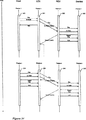
【0173】
図29は、本発明にしたがう大量読取転送を示すシーケンスダイアグラムである。前記大量読取転送は、図18に示したような非同期入力転送の特殊な場合である。
【0174】
フレーム1において、ホストPC内のコントロールロジック(500)が、特定USB機能に宛てた、データ入力に関する要求を発生する。前記要求は、InAddrパケットとしてLEXサブシステムに送信される。LEXサブシステム内のコントロールロジック(501)は、そのInAddrパケットをREXサブシステムに送るのに追加して、握手承認通知が必要であることを前記REXサブシステムに対し通知する。コントロールロジック(501)は、合成否定的受信通知パケットを作成し、それをNakパケットとしてホストPCに対し送信する。LEXサブシステムが、要求された情報をREXサブシステムから受信する前に、同一情報に関する追加要求をホストPCから受けたとき、LEXサブシステムは前記追加要求を吸収して、追加Nakパケットを作成する。
【0175】
REXサブシステム内のコントロールロジック(502)は、InAddrパケットをLEXサブシステムから受信して、前記パケットを周辺装置に対して送る。周辺装置内のコントロールロジック(503)は、適切な情報を組み立てて、それをデータパケットとしてREXに対し送信する。REX内のコントロールロジック(502)が、前記データパケットを受信し、発生源周辺装置のアドレスを前記データパケットに追加付着して、それをLEXに送る。REX内のコントロールロジック(502)は、合成受信通知パケットを作成しそれをAckとしてパケットとして周辺装置に対し送信する。
【0176】
ホストPC内のコントロールロジック(500)は、同一USB機能宛の、データ入力に関する追加要求を作成する。LEX内のコントロールロジック(501)が、前記入力データは既にREXから受信しており、メモリに記憶されていることを認識する。前記コントロールロジック(501)は、前記記憶入力データをメモリから回復して、それをデータパケットとしてホストPCに送信する。ホストPC内のコントロールロジック(500)が、要求されたデータパケットを受け取り、LEXにAckを送信することによりその受信を通知する。
【0177】
図30は、本発明にしたがう大量書込転送を示すシーケンスダイアグラムである。前記大量書込は、図20に記述したような非同期出力転送の特殊な場合である。
【0178】
フレーム1において、ホストPC内のコントロールロジック(500)が、特定USB機能に宛てた、データ出力通知を発生する。前記通知は、OUTAddrパケットとし、データパケットを続けて、LEXサブシステムに対し送信される。LEXサブシステム内のコントロールロジック(501)は、そのOUTAddrパケットとデータパケットを、REXサブシステムに対し送るのに追加して、握手承認通知が必要であることを前記REXサブシステムに通知する。コントロールロジック(501)は、合成否定的受信通知パケットを作成し、それをNakパケットとしてホストPCに対し送信する。LEXサブシステムが、必要な受信通知をREXサブシステムから受信する前に、同一情報に関する追加通知をホストPCから受けたとき、LEXサブシステムは前記追加通知を吸収して、追加Nakパケットを作成する。
【0179】
REXサブシステム内のコントロールロジック(502)は、OUTAddrパケットとデータパケットをLEXサブシステムから受信し、前記パケットを周辺装置に対して送る。周辺装置内のコントロールロジック(503)は、積極的受信応答を組み立てて、それをAckパケットとしてREXに対し送信する。REX内のコントロールロジック(502)が、前記Ackパケットを受信し、発生源周辺装置のアドレスを前記Ackパケットに追加付着して、それをLEXに対し送る。
【0180】
ホストPC内のコントロールロジック(500)は、同一USB機能に宛てた、データ出力に関する追加通知を作成する。LEX内のコントロールロジック(501)が、前記出力データに対応する受信通知は既にREXから受信しており、メモリに記憶されていることを認識する。前記コントロールロジック(501)は、前記記憶された受信通知をメモリから回復して、AckパケットとしてホストPCに対し送信する。
【0181】
図31は、本発明にしたがう割込イン転送を示すシーケンスダイアグラムである。前記割込イン転送は、図18に示したような非同期入力転送の特殊な場合である。
【0182】
フレーム1において、ホストPC内のコントロールロジック(500)が、特定USB機能に宛てた、データ入力要求を発生する。前記要求は、InAddrパケットとしてLEXサブシステムに対し送信される。LEXサブシステム内のコントロールロジック(501)は、そのInAddrパケットを、REXサブシステムに対して送るのに追加して、握手承認通知が必要であることを前記REXサブシステムに通知する。コントロールロジック(501)は、合成否定的受信通知パケットを作成し、それをNakパケットとしてホストPCに対し送信する。
【0183】
REXサブシステム内のコントロールロジック(502)は、InAddrパケットをLEXサブシステムから受信し、前記パケットを周辺装置に対して送る。周辺装置内のコントロールロジック(503)は、適切な情報を組み立てて、それをデータパケットとしてREXに送信する。REX内のコントロールロジック(502)が、前記Ackパケットを受信し、発生源周辺装置のアドレスを前記データパケットに追加付着して、それをLEXに送る。REX内のコントロールロジック(502)は、合成受信通知パケットを作成して、それをAckパケットとして周辺装置に対し送信する。
【0184】
引き続くフレーム「n」において、ホストPC内のコントロールロジック(504)が、同一USB機能に宛てた、データ入力に関する追加要求を作成する。LEX内のコントロールロジック(505)が、前記入力データは既にREXから受信しており、メモリに記憶されていることを認識する。前記コントロールロジック(505)は、前記記憶入力データをメモリから回復して、それをデータパケットとしてホストPCに対し送信する。ホストPC内のコントロールロジック(504)が、要求されたデータパケットを受け取り、LEXにAckを送信することによりその受信を通知する。
【0185】
図32は、本発明にしたがう割込アウト転送を示すシーケンスダイアグラムである。前記割込アウト転送は、図20に示したような非同期出力転送の特殊な場合である。
【0186】
フレーム1において、ホストPC内のコントロールロジック(500)が、特定USB機能に宛てた、データ出力通知を発生する。前記通知は、OUTAddrパケットとし、データパケットをそれに続けて、LEXサブシステムに対し送信される。LEXサブシステム内のコントロールロジック(501)は、そのOUTAddrパケットとデータパケットをREXサブシステムに対して送るのに追加して、握手承認通知が必要であることを前記REXサブシステムに通知する。コントロールロジック(501)は、合成否定的受信通知パケットを作成し、それをNakパケットとしてホストPCに送信する。
【0187】
REXサブシステム内のコントロールロジック(502)は、OUTAddrパケットとデータパケットをLEXサブシステムから受信し、前記パケットを周辺装置に対して送る。周辺装置内のコントロールロジック(503)は、積極的受信通知応答を組み立てて、それをAckパケットとしてREXに送信する。REX内のコントロールロジック(502)が、前記Ackパケットを受信し、発生源周辺装置のアドレスを前記Ackパケットに追加付着して、それをLEXに送る。
【0188】
引き続くフレーム「n」において、ホストPC内のコントロールロジック(504)が、同一USB機能に宛てた、データ出力に関する追加通知を作成する。LEX内のコントロールロジック(505)が、前記出力データに対応する受信通知は既にREXから受信しており、メモリに記憶されていることを認識する。前記コントロールロジック(505)は、前記記憶された受信通知をメモリから回復して、AckパケットとしてホストPCに送信する。
【0189】
図33は、本発明にしたがう制御転送を示すシーケンスダイアグラムである。前記制御転送は、図18に示したような非同期入力転送の特殊な場合である。
【0190】
フレーム1において、ホストPC内のコントロールロジック(500)が、特定USB機能に宛てて、周辺装置設定通知を発生する。前記通知は、設定パケットとし、データパケットを続けて、LEXサブシステムに対し送信される。LEXサブシステム内のコントロールロジック(501)は、その設定パケットとデータパケットをREXサブシステムに対し送るのに追加して、握手承認通知が必要であることを前記REXサブシステムに通知する。コントロールロジック(501)は、合成肯定的受信通知パケットを作成し、それをAckパケットとしてホストPCに送信する。
【0191】
REXサブシステム内のコントロールロジック(502)は、設定パケットとデータパケットをLEXサブシステムから受信して、前記パケットを周辺装置に送る。周辺装置内のコントロールロジック(503)は、積極的受信応答を組み立てて、それをAckパケットとしてREXに送信する。REX内のコントロールロジック(502)が、前記Ackパケットを受信し、発生源周辺装置のアドレスを前記Ackパケットに追加付着して、それをLEXに送る。
【0192】
任意選択で、周辺装置が信号を無事受信したことを確認するため、LEXは、REXからの積極的受信応答を待つ。
【0193】
図34は、本発明にしたがう低速割込イン転送を示すシーケンスダイアグラムである。前記低速割込イン転送は、図18に示したような非同期入力転送及び、図31に示したような割込イン転送の特殊な場合である。
【0194】
フレーム1において、ホストPC内のコントロールロジック(500)が、特定の低速USB機能宛に、データ入力要求を発生する。前記要求は、低速InAddrパケットの続くPreパケットとしてLEXサブシステムに送信される。LEXサブシステム内のコントロールロジック(501)は、そのPreパケットとInAddrパケットを、REXサブシステムに対して送るのに追加して、握手承認通知が必要であることを前記REXサブシステムに通知する。コントロールロジック(501)は、合成否定的受信通知パケットを作成し、それをNakパケットとしてホストPCに送信する。
【0195】
REXサブシステム内のコントロールロジック(502)は、そのPreパケットとInAddrパケットをLEXサブシステムから受信し、前記パケットを周辺装置に対して送る。周辺装置内のコントロールロジック(503)は、適切な情報を組み立てて、それを低速データパケットとしてREXに対し送信する。REX内のコントロールロジック(502)が、前記データパケットを受信し、発生源周辺装置のアドレスを前記データパケットに追加付着して、それをLEXに送る。REX内のコントロールロジック(502)は、合成承認パケットを作成して、それを低速Ackパケットの続くPreパケットとして周辺装置に送信する。
【0196】
引き続くフレーム「n」において、ホストPC内のコントロールロジック(504)が、同一USB機能に宛てて、データ入力に関する追加要求を作成する。LEX内のコントロールロジック(505)が、前記入力データを既にREXから受信しており、メモリに記憶されていることを認識する。前記コントロールロジック(505)は、前記記憶された入力データをメモリから回復して、それを低速データパケットとしてホストPCに対し送信する。ホストPC内のコントロールロジック(504)が、要求されたデータパケットを受信し、低速Ackパケットの続くPreパケットの送信により、その受信をLEXに通知する。
【0197】
図35は、本発明にしたがう低速割込アウト転送を示すシーケンスダイアグラムである。前記低速割込アウト転送は、図20に記述したような非同期出力転送及び、図32に記述したような、割込アウト転送の特殊な場合である。
【0198】
フレーム1において、ホストPC内のコントロールロジック(500)が、特定USB機能に宛てた、データ出力定通知を発生する。前記通知は、Preパケットとして、OUTAddrパケットを続け、第二Preパケットを続け、データパケットを続けて、LEXサブシステムに送信される。LEXサブシステム内のコントロールロジック(501)は、そのPreパケット、OUTAddrパケット、第二Preパケット、及びデータパケットをREXサブシステムに対して送るのに追加して、握手承認通知が必要であることを前記REXサブシステムに通知する。コントロールロジック(501)は、合成否定的受信通知パケットを作成し、それを低速NakパケットとしてホストPCに送信する。
【0199】
REXサブシステム内のコントロールロジック(502)は、Preパケット、OUTAddrパケット、第二Preパケット、及びデータパケットをLEXサブシステムから受信し、前記パケットを周辺装置に対して送る。周辺装置内のコントロールロジック(503)は、積極的受信応答を組み立てて、それを低速AckパケットとしてREXに対し送信する。REX内のコントロールロジック(502)が、前記Ackパケットを受信し、発生源周辺装置のアドレスを前記Ackパケットに追加付着し、それをLEXに対して送る。
【0200】
引き続くフレーム「n」において、ホストPC内のコントロールロジック(504)が、同一USB機能に宛てた、データ出力に関する追加通知を作成する。LEX内のコントロールロジック(505)が、前記データ出力に相当する受信通知を既にREXから受信しており、メモリに記憶していることを認識する。前記コントロールロジック(505)は、前記記憶された受信通知をメモリから回復して、それを低速AckパケットとしてホストPCに対し送信する。
【0201】
本発明にしたがって、前に規定した手段、目的、及び利点を完全に満足するUSB周辺装置が、ここに提供されたことは明らかである。本発明の特定実施例を記述したので、それらの代替案、修正案、及び変形が、当業者により指摘されるであろうこと、及び本明細書は、このような代替案、修正案、及び変形を、従属の請求項の範囲内に入るものとして、包含することは、理解されるであろう。
【0202】
明確にするため付け加えると、別途の説明がない限り、用語「含む」及び、「から成る」及び「から構成される」のような派生語は、本明細書の記述及び請求項の中で使用するとき、その他の添加物、構成部品、完全体及びステップを排除する意図はない。
【図面の簡単な説明】
【図1】 従来型のUSBハブ並びにUSB装置を装備されたPC。
【図2】 本発明による広域(Extended Range)ハブ並びにUSB装置を装備したPCである。
【図3】 信号配信システムとしてUTP配線を用いて操作するために設計された本発明の実施形態の略図。
【図4】 USBプロトコルによる等時性送信の時間経過図。
【図5】 本発明による等時性送信(伝送)(transfer)の時間経過図。
【図6】 本発明によるローカル伸張器の一実施形態の概略図。
【図7】 本発明によるリモート伸張器の一実施形態の概略図。
【図8】 本発明による等時性入力送信の順序を表す図。
【図9】 本発明による別の等時性入力送信図。
【図10】 本発明による等時性出力送信の順序図。
【図11】 本発明によるLEXコントローラーの論理図。
【図12】 本発明による強化(enhanced)LEXコントローラーの論理図。
【図13】 残留パケットを取り除き可能にするLEXコントローラーをさらに強化する論理図。
【図14】 本発明によるREXコントローラーの論理図。
【図15】 本発明による強化REXコントローラーの論理図。
【図16】 USBプロトコルによる非同期送信の時間経過図。
【図17】 本発明による非同期送信の時間経過図。
【図18】 本発明による非同期入力送信の順序図。
【図19】 本発明による別の非同期入力送信の順序図。
【図20】 本発明による非同期出力送信の順序図。
【図21】 本発明による別の非同期出力送信の順序図。
【図22】 本発明によるLEXコントローラーの論理図。
【図23】 本発明による強化LEXコントローラーの論理図。
【図24】 本発明によるREXコントローラーの論理図。
【図25】 本発明によるREXコントローラーの概略図。
【図26】 本発明によるリンク層パケット出力の順序図。
【図27】 本発明によるリンク層パケット入力の順序図。
【図28】 本発明によるリンクコントローラーの論理図。
【図29】 本発明によるバルクリード送信の順序図。
【図30】 本発明によるバルクライト送信の順序図。
【図31】 本発明による割り込み(interrupt)イン送信の順序図。
【図32】 本発明による割り込みアウト送信の順序図。
【図33】 本発明によるコントロール送信の順序図。
【図34】 本発明による低速割り込みイン送信の順序図。
【図35】 本発明による低速割り込みアウト送信の順序図。[0001]
(Technical field)
The present invention relates to a method and an apparatus for transmitting a signal to a device using a general serial bus port, and more particularly, to a method for communicating between devices using a port over an extended range.
[0002]
(Conventional technology)
A general serial bus (USB) is a technology designed to allow an average user to connect a wide range of peripheral devices to a personal computer. Because the technology maintains all common peripherals such as keyboards, mice, speakers, modems, joysticks, cameras, and many other common devices, the serial and parallel ports are swapped for use today. For example, Apple iMac ™ only supports USB ports. In addition, most personal computers (PCs) manufactured since 1997 are equipped with USB ports.
[0003]
USB was produced by an agreement between seven large companies in the computer and communications equipment market. These companies were Intel, Compaq, Microsoft, Nontel, NC, Digital, and IBM. Specifications that define USB (for example, Intel, etc., general serial bus specifications, revised version 1.0, January 1996; revised version 1.1, September 1998, subsequent revisions and changes (revision 2.0), etc. Collectively, referred to as the USB specification, which may include future changes and revisions, is disadvantageous and is managed by a public company organization known as the USB Forum. The USB specification establishes a great deal of rules that must be met to satisfy the USB standard. The USB specification also defines a number of terms, definitions adopted for the purposes of this specification.
[0004]
As an example, in the revised USB specification, 1.0, a single USB domain is required to support 127 devices operating on a distribution medium that provides a maximum bandwidth of 12 Mbps. Revision 2.0, however, demonstrates a revision of the USB specification that allows a bandwidth of 480 Mbps.
[0005]
However, all known USB specifications currently limit the distance that the device can be separated up to 5 meters from the host PC. In theory, this distance limit can be increased to 30 meters when a series of USB hubs and devices are used to support the increased PC population rather than the increased distance. This parallel hub measure is expensive and ugly. As an example, to support a single device in the 30 meter range, consumers must now purchase five hubs, each costing $ 50. In addition, at least two of these hubs need to have power supplies. Since the individual cables between the hubs are limited to 5 meters, some of the hubs must be placed in very inconvenient and unsafe locations.
[0006]
Therefore, there is a need for a method and apparatus that installs a USB device at a distance that is far from the host PC. For example, to meet the standards governing the wiring of commercial buildings, a non-distant distance of at least 100 meters is required (for example, TIAVEIA-558-A, Commercial Building Telecommunications Cabling Standard, Telecommunications Industry Association, 1995 October). Distribution cables are typically not received between endpoints in a wireless closet or work area, for example, so this criterion must be met without the need for an intermediate repeater. Furthermore, even if the cable is accepted, the cable standard does not allow it to be inserted into the actual device other than the endpoint.
[0007]
Providing a wide range of possibilities also subsidizes real USB devices and provides new applications for them. For example, a simple residential or SOHO (small office or home office) monitoring system can be configured by connecting a consumer camera to a central PC. The overhead monitor can be controlled with a remote keyboard and mouse. The door phone entrance system can be monitored from any office in a commercial building. Many other applications are possible.
[0008]
However, the USB specification currently does not permit wide area use. For example, another requirement of the USB specification is that each device's access to the distributed communication bus is controlled by a single host controller. When the host controller directs information on a particular device to be placed on the distribution bus, the requested information should be received by the host controller within 16 bit times of the host controller generating the indication. In fact, by limiting the time during which no information is transmitted, the USB specification reliably provides a high bandwidth utilization effect. However, since one bit time at 12 Mbps is equivalent to the time of an electronic signal flowing through a copper wire of almost 17 meters, and one bit time at 480 Mbps is equally short distance, these requirements are also the physical requirements of USB devices. Limits the scope.
[0009]
In addition, USB devices must respond to requests from the host controller in the 16-bit time range, but 7.5 bit times are assigned to the delay in the USB device and its connected 5-meter cable. This allocation only holds 8.5 bit times at 12 Mbps for further cable delay. The time represented by 8.5 bit time is equal to the delay due to the electronic signal flowing through the cable of about 144 meters. However, this cable length is insufficient to satisfy the 200-meter cable required for the previous cable specifications.
[0010]
In this way, it is impossible to provide a USB device separated in a wide area.
[0011]
However, another feature of the USB specification is that the USB specification (or protocol) isolates access to the bus distributed to separate units known as frames. Each frame is designed to last 1ms.
[0012]
Furthermore, the USB specification requires that at least four separate data flows or traffic be recognized: isochronous transmission, control transmission, blocking transmission, and bulk transmission.
[0013]
Isochronous data transmission is characterized as data transmission in which data flows at a timing that is essentially continuous, with a receiving mechanism capability to receive and utilize incoming data at a constant rate.
[0014]
In particular, it must be specified that timely information propagation is an aspect of isochronous transmission that reliably wastes voltage transition losses in the data flow. In particular, there is no attempt to retransmit data lost in previous transmissions. For example, in an isochronous video signal, the loss of one frame of information is usually not significant and there is no interest in recovering lost frames. Instead, the host controller is generally more involved in transmitting and receiving the current frame. Thus, isochronous data transmission is said to be a time-related data transmission system.
[0015]
This type of data transmission waits for asynchronous data transmissions that continue to proceed independently of each other until the accompanying process must block the other process, and the realization that one process occurs in the other process before continuing It is separate from isochronous data transmission that maintains the processing that must be done. Therefore, these data transmission methods are not time related, but can be said to be a correct response to any required request.
[0016]
In order to provide a method and apparatus capable of transmitting data over a wide area, the present invention provides basic characteristics of isochronous and asynchronous data transmission, more generally time-related or non-time-related data transmission, and a specified protocol. Use the presence of a frame.
[0017]
Thus, while USB technology proves to be usable, it is specified in a wide area by providing a data transmission equipment, a method and apparatus that enables the use of USB specifications, especially time-related or non-time-related data transmission equipment. It would be desirable to provide improvements to the technique.
[0018]
Accordingly, it is an object of the present invention to provide a method and apparatus that enables communication to devices, hubs, controllers, and other devices in accordance with the USB specification and in a wider range than currently permitted under the USB specification. It is.
[0019]
Another object of the present invention is that a wide area is achieved without the need for intermediate hubs, repeaters or other electronic signal regeneration methods.
[0020]
Yet another object of the present invention is to change the hardware and software of real devices, hubs and controllers supported by the system, especially isochronous or asynchronous systems that operate under the USB specification. It is not necessary. Therefore, the present invention can be connected to a network consisting of conventional and wide-range therapeutic devices.
[0021]
Yet another object of the present invention is that the device is very cost effective in harmony with the expanded population of devices targeted by the USB industry.
[0022]
These and other objects of the invention will be apparent from the specification and attained by the invention described hereinafter.
[0023]
The present invention provides, in its normal form, a method for transmitting data to a host controller and peripheral devices over a wide area, the method comprising:
a. Sending the first original, output digital signal from the host controller to the local decompressor unit
b. Arbitrary conversion of the output digital signal into a converted output signal having a format suitable for wide-area transmission
c. Transmission of either the output digital signal or the converted output signal on the signal distribution system as an output transmission signal
d. Reception of the output transmission signal at the remote expander unit
e. Arbitrary conversion of the output transmission signal into the first original output digital signal
f. From a remote stretcher to at least one peripheral device
Transport of the first original output digital signal
g. Response digital signal reception from the peripheral device at the remote decompressor
h. Arbitrary conversion of the response digital signal into a converted response signal having a format suitable for wide-area transmission
i. Transmission of either the response digital signal or the converted response signal on the signal distribution system as a response transmission signal
j. Reception of the response transmission signal at the local decompressor
k. Arbitrary conversion of the response transmission signal into the original response digital signal
l. Accumulation of the response digital signal as an accumulation response digital signal until the subsequent reception of the original output digital signal similar to or similar to the first original output digital signal from the host controller
m. In response to the subsequent original output digital signal, the storage response digital signal is transmitted to the host controller.
Consists of.
[0024]
With regard to isochronous data flow, generally time related data flow, the first or following original output digital signal is a requirement for time related data, preferably isochronous data flow.
[0025]
The purpose of this specification is that the term time-related data flow relates to a data flow such as an isochronous data flow that is less affected by the frame loss from the previous transmission and does not require retransmission. Means.
[0026]
(Disclosure of the Invention)
In a preferred embodiment, all digital signals conform to the USB specification (rather than for the distance between devices), and all digital signals, and more particularly response digital signals, represent isochronous data.
[0027]
In step (1), the digital signal is described as being accumulated. This accumulation time, as well as another accumulation time described herein, may be very short. For example, if the response signal is temporarily received to respond to the original digital signal, the response signal may also be transmitted immediately with the shortest integration time.
[0028]
In a further preferred embodiment, the present invention provides a method for transmitting isochronous data according to a USB specification in which isochronous data is transmitted from a peripheral device and received by a host controller, the method comprising:
a. Send requests for isochronous data from host controller to local stretcher
b. Send requests for isochronous data from the local decompressor to the remote decompressor on the signal distribution system
c. Transport of the transmitted request for isochronous data to at least one peripheral device
d. Transmission of requested isochronous data from the peripheral to the remote decompressor
e. Transmission of the requested isochronous data from the remote decompressor over the signal distribution system to the local decompressor
f. Storage of the requested isochronous data in the packet buffer at the local decompressor
g. Sending subsequent requests for isochronous data from the host controller to the local decompressor
h. Receiving the subsequent request for isochronous data at the local decompressor; and
I. Recovery of isochronous data stored from the local decompressor
II. Propagation of isochronous data stored in the host controller
III. Sending subsequent requests for isochronous data on the signal distribution system from the local decompressor to the remote decompressor; and
IV. It consists of repeating steps (c) to (h) for the subsequent and further requests for isochronous data.
In a still further preferred embodiment, the present invention provides a method comprising the following steps after the foregoing:
i. Determine if the local decompressor already owns the requested isochronous data
ii. Generation of composite data when the requested isochronous data does not exist
iii. Propagating the synthetic isochronous data to the host controller
It is.
[0029]
The present invention also provides a method for transmitting isochronous data according to the USB specification in which isochronous data is transmitted from a host controller and received by a peripheral device, the method comprising:
a) Receiving the original notification of the isochronous host controller at the local decompressor
b) Transmission of the original notification of the isochronous data from the local decompressor to the remote decompressor on the signal distribution system.
c) Receiving the transmitted original notification of isochronous data at the remote decompressor
d) Transmission of the sent notification of asynchronous data to at least one peripheral device
e) The original isochronous data packet from the host controller is received by the local decompressor.
f) Transmission of the original isochronous data packet over the signal distribution system from the local decompressor to the remote decompressor.
g) The transmitted original isochronous data packet is received by the remote decompressor.
h) consists of transmitting the transmitted original isochronous data packet to at least one peripheral device.
[0030]
For asynchronous data flows, generally non-time related data flows, the present invention provides a method wherein the first or subsequent original, output digital signal is a request for time related data, preferably asynchronous data flow. provide.
[0031]
For the purposes of this specification, the term non-time related data refers to a data flow, such as an asynchronous data flow in which no frame loss from previous transmissions has been received and correct transmission of current information is required. means.
[0032]
In a preferred embodiment, all digital signals that meet the USB specification (apart from the distance between devices) and digital signals, particularly response digital signals, represent asynchronous data.
[0033]
In a further preferred embodiment, the present invention provides an asynchronous data transmission method according to the USB specification in which asynchronous data is transmitted from a peripheral device and received by a host controller, the method comprising:
a) Receiving the original request for asynchronous data from the host controller at the local decompressor
b) Transmission of the original request for the asynchronous data on the signal distribution system from the local decompressor to the remote decompressor.
c) Receiving the transmitted original request for asynchronous data at the remote decompressor
d) Transmission of the transmitted original request for asynchronous data to at least one peripheral device.
e) Asynchronous data requested by peripheral devices is received by remote decompressor
f) Transmission of the requested asynchronous data over the signal distribution system from the remote decompressor to the local decompressor.
g) Accumulating the requested asynchronous data in the packet buffer of the local decompressor
h) The local decompressor receives a request for subsequent asynchronous data from the host controller, and
i) Send a request for subsequent asynchronous data from the local decompressor to the remote decompressor over the signal distribution system.
ii) Propagate subsequent requests sent for asynchronous data to at least one peripheral device
iii) Receiving asynchronous data requested from peripheral devices with remote decompressor
i) additionally receiving subsequent requests for asynchronous data from the host controller in step (h) at the local decompressor;
i) Recover asynchronous data accumulated from packet buffer
ii) Propagate the recovered asynchronous data to the host controller
j) Receive output confirmation signal from host controller with local expander
k) Arbitrary conversion of the output confirmation signal into a conversion confirmation signal having a format suitable for transmission over a wide area
l) Transmit either the output confirmation signal or the conversion confirmation signal as a confirmation transmission signal on the signal distribution system.
m) Receive confirmation transmission signal with remote expander unit
n) Arbitrary conversion of confirmation transmission signal to output confirmation signal
o) Transmitting the output confirmation signal from the remote decompressor to at least one peripheral device.
[0034]
In a preferred feature, the method also provides the following further steps after said step (b):
i) Determine if the local decompressor already has the requested asynchronous data
ii) Generate a negative confirmation packet if the requested asynchronous data does not exist
iii) Transmit the negative confirmation packet to the host controller
In a further preferred embodiment, the present invention also provides the method related to the present invention, which provides an asynchronous data transmission method according to the USB specification in which asynchronous data is transmitted from the host controller and received by the peripheral device. And this way
a) Receiving the original notification of asynchronous data from the host controller with the local decompressor
b) Send original notification of asynchronous data from local decompressor to remote decompressor on signal distribution system
c) Receive original notification with asynchronous data sent by remote decompressor
d) Transmit notification of asynchronous data sent to at least one peripheral device
e) The original asynchronous data packet from the host controller is received by the local decompressor.
f) Send the original asynchronous data from the local decompressor to the remote decompressor over the signal distribution system
g) Receive the transmitted original asynchronous data packet with the remote decompressor
h) Transmit asynchronous data packets sent to at least one peripheral device
i) Receive upstream confirmation packet from peripheral device with remote decompressor
j) Transmit upstream confirmation packet from remote decompressor to local decompressor on signal distribution system
k) Accumulating uplink confirmation packets in the packet buffer
l) Receive subsequent notification of asynchronous data packet from host controller at local decompressor
m) Receive subsequent asynchronous data packets from the host controller at the local decompressor, and
i) Recover the uplink confirmation packet stored from the packet buffer
ii) Transmit recovered uplink confirmation packet to host controller
Made up of.
[0035]
More preferably, the method comprises the following steps:
i) Determining whether the local decompressor already has an uplink confirmation packet
ii) Generates a negative confirmation packet if no upstream confirmation packet exists
iii) Transmit the negative confirmation packet to the host controller
In a system in which the monitoring time is imposed after a data packet is transmitted (so as not to transmit another packet prematurely), a preferred embodiment of the present invention provides a method comprising the following steps in addition to the method described above: To do.
a) Receiving downstream data packet by remote decompressor
b) The transmission type of downstream data packet is determined by the remote decompressor
c) Sending a downstream data packet from the remote decompressor to the USB device
d) A transmission monitoring timer is set to a value in the determined transmission type.
e) Downstream transmission is prohibited until the monitoring timer is completed
[0036]
In preferred embodiments of either time-related or non-time-related data, the wide area is equal to or greater than 5 meters, preferably greater than 30 meters, more preferably greater than 100 meters. In particular, the distance between the local stretcher and the remote stretcher is 5 meters or more, preferably 30 meters or more, more preferably 100 meters or more.
[0037]
As in the prior art, the method of the present invention can be used in a system in which the host controller is a PC and the peripheral device is, for example, a camera, a mouse, a keyboard, a monitor or a speaker or a plurality of speakers.
[0038]
A number of different signal distribution systems are also used, preferably the signal distribution system utilizes unshielded twisted pair (UTP) wires (or cables). However, other signal distribution systems such as coaxial cables, cut-off twisted pairs, wireless transmission, fiber optic systems using fiber optic cables are also available.
[0039]
In another object, the present invention also provides an apparatus for transmitting a digital signal over a wide area comprising:
[0040]
A local decompressor comprising means for the host controller to receive a request for a data signal from a host controller connected to the local decompressor;
Means in a local decompressor for generating an output transmission signal;
Means in said local stretcher for transmitting an output transmission signal to a remote stretcher where signals are transmitted over the signal distribution system;
A remote decompressor comprising means for receiving an output transmission signal;
Means in a remote decompressor for generating a digital signal from an output transmission signal;
Means for transmitting a digital signal to at least one peripheral device connected to the remote stretcher at the remote stretcher;
Means for receiving the upstream digital signal from the peripheral device in the remote decompressor;
Means for converting an upstream digital signal to an upstream transmission signal in a remote decompressor;
Means for transmitting an upstream transmission signal transmitted over a signal distribution system to a local decompressor in a remote decompressor;
Means for receiving the upstream transmission signal at the local decompressor;
Means for generating a digital signal from upstream transmission at a local decompressor; and
A means in a remote stretcher that sends a digital signal to a host controller.
[0041]
In an embodiment, the data signal is a time related data signal, preferably an isochronous data signal. For time related data signals (or streams), preferably the local decompressor
a) Means for storing upstream signals as stored upstream signals
b) Means for analyzing the digital signal from the host controller to recognize subsequent requests for transmission of time-related digital signals
c) It comprises means for transmitting an upstream signal stored in the host controller in response to a subsequent request.
[0042]
In another embodiment, the data signal is a non-time related data signal, preferably an asynchronous data signal. Thus, with respect to non-time related data signals, the present invention provides an apparatus for transmitting digital signals over a wide area comprising:
a) A local decompressor comprising means for receiving a request for a non-time related data signal, wherein the non-time related data signal is a digital signal conforming to the USB specification from a host controller connected to the local stretcher. is there
b) means in the local expander for generating the output transmission signal c) means for transmitting the output transmission signal transmitted over the signal distribution system in the local expander to the remote expander
d) A remote decompressor comprising means for receiving an output transmission signal
e) Means in the remote decompressor for generating a digital signal from the output transmission signal
f) Means in the remote decompressor for transmitting a digital signal to at least one peripheral device connected to the remote decompressor g) Means for receiving the upstream digital signal from the peripheral device in the remote decompressor
h) Means for converting an upstream digital signal into an upstream transmission signal in a remote decompressor
i) In the remote decompressor, means for transmitting the upstream transmission signal transmitted on the signal distribution system to the local decompressor
j) Means for receiving upstream transmission signal by local decompressor
k) Means for generating a digital signal from upstream transmission in a local decompressor
l) Consists of means in a local decompressor that transmits a digital signal to the host controller.
[0043]
Preferably, the non-time related signal is asynchronous data.
[0044]
In a preferred embodiment, the present invention also provides a local stretcher device comprising:
a) Means for accumulating the rising signal as the accumulated upstream signal
b) means for analyzing the digital signal from the host controller to recognize a subsequent request for transmission of the non-time related digital signal; c) means for transmitting the upstream signal stored in the host controller in response to the subsequent request. .
[0045]
DESCRIPTION OF PREFERRED EMBODIMENTS
Multiple signal distribution systems may be used as described above, and preferably the signal is transmitted through a signal distribution system that utilizes uninterrupted twisted pair (UTP) copper wire. By using this device connection method, an inexpensive and effective data transmission means is provided. However, in other embodiments of the system, the signal is transmitted through a coaxial cable, wireless transmission method, or fiber optic distribution system.
[0046]
Although the method and apparatus of the present invention have general functions with varying applications, it is fundamentally important that the data transmission method and apparatus of the present invention (except for distance requirements) conform to the USB specification. That is. Preferably, the original signal from the host controller is a request for data from the peripheral device. More preferably, the required data is from a peripheral device such as a camera, mouse, keyboard, monitor or speaker.
[0047]
For time-related data flows, particularly in operations utilizing the method and apparatus of the present invention in applications involving wide area transmission, it is preferred that the apparatus be able to recognize isochronous transmission when data is received. The data in the isochronous transmission is further accumulated in the system for a certain time. Therefore, the data received in a specific frame is transmitted to the subsequent frame after being accumulated. Furthermore, a preferred embodiment of the present invention is capable of accumulating and retransmitting isochronous transmissions originating from multiple destinations.
[0048]
In the operation of the preferred embodiment of the present invention, the host controller (preferably a PC) generates a request for isochronous data transmission to the device. The request is received by the device of the present invention and retransmitted to the target device. The requested isochronous transmission response is received by the device from the target device, and the isochronous data is stored in a memory inside the device. In subsequent frames, the host controller again generates a request for transmission of isochronous data to the target device. The device again resends this request to the target device, but the device recognizes that it currently has isochronous data from the target device stored in internal memory. The device sends this data to the host controller within a 16-bit time margin associated with the current request within the current frame. In order to respond to the request for the current frame in this way, the device utilizes the data accumulated in the previous frame.
[0049]
When a packet is received from the target device, no other data request is received from the host controller, and the last received data packet or group of packets (hereinafter referred to as residual data) may be removed from the system. Preferably, they are not sent when and when other requests are received from the host controller. Preferably, the above method is changed to the following steps to achieve the object. That is,
i) Detected at the start of a new frame.
ii) Check the properties of each packet buffer.
iii) Check if the data packet contained in the inspected packet buffer has been stored for at least one complete frame period.
iv) If the data packet contained in the packet buffer is accumulated for at least one frame period, the data packet is discarded.
v) Repeat step (i) via step (iv) for each packet buffer in the system.
[0050]
In a modified embodiment of the invention, the device processes the first request for upstream transmission of isochronous data in a unique way. This unique method requires the device to generate its own combined uplink data packet, and the generation of the combined data packet is described below.
[0051]
It is possible that packets sent from the remote decompressor do not arrive at the local decompressor in the order expected by the local decompressor. In order to avoid this difficulty, the method of the present invention comprises the following steps. That is,
i) Storage of the address of the peripheral device requested by the remote decompressor unit after the local decompressor carries forward requests for isochronous data.
After transmitting the requested isochronous data from the peripheral device to the remote decompressor, it consists of the following steps:
i) recovering the requested peripheral address at the remote decompressor unit; and
ii) adding the recovery address to the requested isochronous data.
It is.
[0052]
For non-time related data streams, especially asynchronous data, signals, streams or transmissions, the device recognizes asynchronous transmissions as they are received during method execution and use of the device of the present invention. Preferably it can be done. The data stored in the asynchronous transmission is accumulated in the system for a certain time. Therefore, the data received for a specific time is accumulated and transmitted for the subsequent time. Accordingly, a preferred embodiment of the invention is that asynchronous transmissions originating from multiple destinations are accumulated and retransmitted.
[0053]
In the operation of the preferred embodiment of the present invention with respect to non-time related data flows, particularly asynchronous data flows, the host controller (preferably a PC) may generate a request to transmit asynchronous data to the device. The request is received by the device of the present invention and retransmitted to the target device. The response of the requested asynchronous transmission is received by the device from the target device, and the asynchronous data is stored in a memory in the device. At a subsequent time, the host controller again generates a request for asynchronous data transmission to the target device. The device again resends this request to the target device. However, it also recognizes that the device currently has asynchronous data stored from the target device in its internal memory. The device sends this data to the host controller within 16-bit time margin in association with the real request at real time. In this way, the device uses the data accumulated at the previous time to meet the real time response time requirement.
[0054]
The term time may be used to apply to the relevant device's selection time (which may include part of the frame, multiple frames, etc.), but is preferably a single frame as defined in the USB specification.
[0055]
As described above, the host controller is preferably a PC. However, the host controller may also be part of a computer system, particularly a networked computer system.
[0056]
By using the method apparatus of the present invention, it is possible to transmit time-related data or non-time-related data, isochronous data or asynchronous data over a wider distance, particularly as specified in the USB specification. It is.
[0057]
(Best Mode for Carrying Out the Invention)
Other objects and related advantages and other features of the present invention will be described with reference to the accompanying drawings. In the following description, similar symbols represent similar elements.
[0058]
The present invention and various objects related thereto will be described with reference to the accompanying drawings.
[0059]
In the drawing, FIG. 1 represents a PC (1) equipped with two conventional USB hubs (2a, 2b) and four standard USB devices (3a, 3b, 3c, 3d). The cable length of the two hubs (2a, 2b) cannot exceed 5 meters with the current USB specification.
[0060]
FIG. 2 shows a PC (1) equipped with a device according to the present invention, to which a wide area hub (7) and four standard USB devices (3a, 3b, 3c, 3d) are connected. The wide area hub consists of two split units, a local stretcher (4) and a remote stretcher (5) connected by a cable (6). In one embodiment according to the invention, the
[0061]
FIG. 3 represents an embodiment according to the invention designed to operate above UTP. In this embodiment, the two split units connected by unshielded twisted pair (UTP) length copper wire (6a) provide the normal functionality provided by a USB hub. The host PC may be connected to a first unit (4) called a local decompressor (LEX). Here, the second unit (6) is referred to as a remote decompressor (REX). REX (6) may be connected to a plurality of USB devices. In this embodiment, four machines are selected as a plurality of machines, but it will be apparent to those skilled in the art that other choices are made within the scope of the invention.
[0062]
The LEX unit (4) is moved closer to the host PC, the REX unit (5) is moved closer to the plurality of USB devices, and the LEX unit (4) is connected with a cable (6a) exceeding a desired UTP length. By connecting the REX unit (5), the operation beyond the expansion distance is completely achieved.
[0063]
FIG. 4 shows the passage of time representing isochronous transmission according to the USB protocol. The figure is configured from the perspective of a USB host controller and is usually included on a PC motherboard (host PC). The USB protocol divides the time added to the shared bus into regular frames every 1 ms of required time. The start of each frame is represented by FIG. 1, FIG. 2, FIG. 3, and FIG. When the host controller is connected to a device over isochronous transmission, the host controller generates a periodic request for data transmission to the device. These requests are represented in FIG. 4 as packets R1, R2, R3, (10, 12, 14). Under the USB protocol, a USB device needs to respond to the request within 16 bit times. In general, transmission ls1 (11) is communicated in response to request R1 (10), and transmission ls2 (13) is communicated in response to request R2 (12) and will continue until the request is completed.
[0064]
FIG. 5 provides a time lapse diagram representing isochronous transmission according to the present invention. The figure illustrates packet advancement through the various subsystems that make up the present invention. A timeline is presented for each component of the host PC (1), local decompressor (LEX) (4), and remote decompressor (REX) (5) shown in FIG.
[0065]
Isochronous transmission is initiated from the host PC (1) by issuing a request for output data R1 (20) to a special USB address and endpoint. The request R1 (20) is accepted by LEX (4) and retransmitted as R1 (25) from the external cable up to REX (5). The retransmitted packet R1 (25) is received by REX (5) and sent as R1 (31) to the target device (for example, one of the
[0066]
The target device generates an output data packet ls1 (32). According to the USB protocol, a device without an integrated cable needs to generate a response within 6.5 bit times of the end of the corresponding request. The output data packet ls1 (32) is received by the REX subsystem (5) and retransmitted as ls1 (26) from the external wire to LEX (4). The retransmitted response ls1 (26) is not immediately transmitted to the host PC (1) but is stored in the memory of the LEX subsystem (4).
[0067]
The host PC (1) informs its output data request R1 (20) that it has not accepted a response, and attempts transmission again by generating a new request R2 (21) at the same USB address and endpoint. When receiving the request R2 (21), the
[0068]
The second request R2 (21) is repeated as R2 (27) through LEX and sent to the device as R2 (33). The target device generates a second response ls2 (34) at LEX that is retransmitted by REX as ls2 (28). The response ls2 (28) is again stored in the memory of the LEX subsystem, and is sent from here to the host PC (1) as a response ls2 (24) to the third request R3 (23). If necessary, the process is repeated with requests R3 (23), R3 (29), R3 (35) and responses ls3 (36), ls3 (30).
[0069]
FIG. 6 shows an embodiment of a local decompressor (LEX) (4) according to the present invention. The embodiment consists of four main blocks. The USB interface (50) connects the host PC to a unit that uses a standard USB cable. The USB interface (50) receives a signal in the USB format from the host PC and transmits a USB packet to the LEX controller (51). The LEX controller (51) determines which response is required for the received packet and generates a USB packet as appropriate. When the LEX controller (51) needs information stored before transmission, the information is stored in the RAM (53).
[0070]
Information that needs to be transmitted to the remote stretcher (REX) (5) is sent to the UTP interface (52) where the information is converted into a digital signal suitable for copper wire propagation.
[0071]
In the opposite direction, the digital signal originating from the remote stretcher (5) is received by the UTP interface (52) and sent to the LEX controller (51). The LEX controller (51) stores any necessary information in the RAM (53) and generates the requested response. Information that needs to be sent to the host PC is sent to the USB interface (50) from which it is sent to the host PC using standard USB hardware and protocols.
[0072]
FIG. 7 represents an embodiment of a remote decompressor (REX) (5) according to the present invention. The embodiment includes a UTP interface (60), a plurality of USB interfaces (63, 64, 65, 66), a REX controller (61), and a RAM (62). The operation of REX (5) is the same as that of LEX (4).
[0073]
FIG. 8 is a diagram illustrating the order of isochronous input transmission according to the present invention. The format used in the figure is attributed to Jacobson et al. (Ivan Jacobson, Magnus Christerson, Patrick Johnson, Gunner Oversight, Object Oriented Software Engineering: A Use Case Driven Approach, Addison Wesley, 1992).
[0074]
In
[0075]
The control logic (103) in the device assembles the requested isochronous data and transmits it as a data payload packet to the REX subsystem. Control logic (102) in the REX subsystem transmits data payload packets to the LEX subsystem. The control logic (101) in the LEX subsystem stores the data payload packet in its buffer memory.
[0076]
In
[0077]
The control logic (107) in the device assembles the requested isochronous data and sends it to the REX subsystem as a data payload packet. Control logic (106) in the REX subsystem transmits data payload packets to the LEX subsystem. The control logic (105) in the LEX subsystem stores the data payload packet in its buffer memory.
[0078]
The above process is repeated for successive frames with distributed control logic (108, 109, 110, 111 as an example).
[0079]
In FIG. 9, a sequence diagram of another isochronous input transmission according to the present invention is provided. Unlike the method described in FIG. 8, this is a method of handling the first request for isochronous input transmission.
[0080]
In
[0081]
At this point in the sequence, another process has been introduced. The control logic (101) in the LEX subsystem generates a composite data packet and transmits it as a data payload packet to the host PC. The composite data packet is a data payload in FIG. 0. The remainder of the protocol handling continues as described in FIG.
[0082]
The USB specification forms a data packet consisting of a single byte packet identifier (PID), a data payload ranging from 0 bytes to 1023 bytes in size, and a 2-byte cycle redundancy check. The composite data packet can thus be constructed by assembling a data packet containing a zero length payload. The composite data packet can thereby be used to satisfy the timing requirements of the USB protocol without compromising the actual information propagated by the protocol.
[0083]
FIG. 10 shows a sequence diagram of isochronous output transmission according to the present invention.
[0084]
In
[0085]
The control logic (120) in the host PC assembles the notified isochronous data and transmits it as a data payload packet to the LEX subsystem. The control logic (121) in the LEX subsystem transmits the data payload packet to the REX subsystem. Control logic (122) in the LEX subsystem transmits the data payload packet to the device. Information is received by control logic (123) in the device.
[0086]
FIG. 11 shows an algorithm for realizing isochronous transmission in the local decompressor (4). In the embodiment according to the present invention described with reference to FIG. 6, the algorithm is implemented in hardware by a LEX controller (51). (For those skilled in the art, this implementation is not special and it is clear that other mechanisms for implementing the algorithm are possible). Hereinafter, the uplink direction of the packet moving from the peripheral device to the host controller and the downlink direction of the packet moving from the host controller to the peripheral device will be described.
[0087]
According to the present invention, the algorithm shown in FIG. 11 is necessary to realize the process function represented by the process block (101, 105, 109) in FIG. 8 and the process block (121) in FIG.
[0088]
After the initial startup or reset, the system is in an idle state (200) and is waiting to receive a message (USB packet). When a packet is received, the packet identifier (PID) field within the packet is examined to determine what type of packet was received and what action is required to process the packet.
[0089]
When the received packet (201) is of type IN, the same packet (202) is transmitted. The system then tests the buffer memory (203) to determine whether an accumulated data packet from the device to which the IN request is directed already exists in the memory. If this stored data packet does not exist in memory, the system returns to the idle state (200). If the stored data packet exists in the memory, the system recovers the stored packet from the memory (204) and sends the packet to the host as a data type packet (205). The system now returns to the idle state (200).
[0090]
If the received packet (206) is moving in the upstream direction with the data type, the system stores the data packet in the buffer memory (207). The system now returns to the idle state (200).
[0091]
If the received packet (208) is of the out-address type, the system transmits the packet again (209) and returns to the idle state (200).
[0092]
If the received packet (210) is moving in the downlink direction with a data type, the system transmits the packet again (211) and returns to the idle state (200).
[0093]
FIG. 12 shows an enhancement algorithm for realizing isochronous transmission in the local decompressor according to the present invention described in FIG. This algorithm is essentially the same as that described in FIG. 11 except that the host generates a request for data and the LEX is still not holding the data it returns to the host. It is. This condition occurs on the first request of an isochronous input session.
[0094]
In FIG. 12, when the received packet (201) is of type IN, the same packet (202) is transmitted. The system then tests the buffer memory (203) to determine whether a stored data packet from the device that the IN request aimed at already exists in the memory. If this stored data packet does not exist in memory, the system generates a composite data packet (212) and transmits the generated packet to the host within the 16-bit time permitted by the USB protocol. If the stored data packet exists in the memory, the system recovers the stored packet from the memory (204), sends the packet to the host as a data type packet (205), and the system now enters the idle state (200). Return.
[0095]
If the received packet (206) is moving in the upstream direction with the data type, the system stores the data packet in the buffer memory (207). The packet aging (Aging) flag with the newly stored packet is reset (214) for the reason described in FIG. The system now returns to the idle state (200).
[0096]
FIG. 13 is a logic diagram that further enhances the LEX controller that allows residual packets to be removed. While the host PC decides to terminate the session, the residual packet can occur during isochronous input transmission when the LEX controller already owns the upstream data packet belonging to the session. This state is an example of packet data payload This is shown in FIG.
[0097]
Under the USB specification, the start of each frame is marked with a unique start-off frame (SOF) signal. The embodiment described in FIG. 13 utilizes this SOF signal to identify and discard packets that are no longer required. The process begins when the SOF signal (221) is received by the local decompressor. The search of the local buffer memory is started by setting the context in the first buffer (222). The packet aging flag of the packet pointed to by the current relationship is tested (223). If the packet age flag is already set, the packet in the buffer is discarded (224). If the packet age flag is not set, the packet age flag is set to ensure that it is discarded in the next frame if the packet has not been transmitted until this time (225).
[0098]
The process is repeated by setting the relationship to the next buffer (227) and continuing until all buffers have been checked, as tested and detected (228).
[0099]
As another precaution to prevent early abandonment of residual packets, whenever a data packet is stored in the buffer memory of the LEX controller, the packet time flag is reset again by step (214) of FIG.
[0100]
FIG. 14 shows an implementation algorithm for isochronous transmission in the remote decompressor. In the embodiment of the present invention described in FIG. 7, the algorithm is realized in hardware by the REX controller (61) (this implementation is not unique, and another mechanism for realizing the algorithm is possible). Is obvious to those skilled in the art). In the following description, an uplink direction of a packet moving from the peripheral device to the host controller and a downlink direction of a packet moving from the host controller to the peripheral device will be described.
[0101]
According to the present invention, the algorithm of FIG. 14 is required to realize the process functions represented by the process blocks (102), (106), (110) of FIG. 8 and the process block (122) of FIG. Is done.
[0102]
After initial startup or reset, the system is in an idle state (230) and is waiting to receive a message (USB packet). When a packet is received, the packet identifier (PID) field within the packet is examined to determine what type of packet was received and what action is required to process the packet.
[0103]
If the received packet (231) is of the IN type, the system retransmits the IN packet and returns to the idle state (230).
[0104]
When the received packet (233) moves in the upstream direction with the data type, the system retransmits the data packet and returns to the idle state (230).
[0105]
When the received packet (235) is of type OUT, the system retransmits (238) the OUT packet and returns to the standby state (230).
[0106]
If the received packet (235) is of type DATA and is flowing out, the system retransmits the DATA packet (238) and returns to the standby state (230).
[0107]
FIG. 15 includes an enhanced algorithm for performing isochronous transfer in the remote decompressor. Under certain conditions, there is a risk that packets sent from the remote decompressor and arriving at the local decompressor are not in the order expected by the local decompressor. The enhancement described in FIG. 15 adds an address field to the packet sent in the in direction so that the local decompressor can identify the source of the packet.
[0108]
Due to the enhancement, when the REX controller receives an IN packet, the address contained in it is stored in the memory (239). The IN packet is then retransmitted (232) as before and the system returns to the standby state (230). When the system receives the next DATA packet moving in the in direction (233), the system recovers the address stored in the memory (240) and retransmits (234) this information to the LEX. Include. The system returns to the standby state (230).
[0109]
FIG. 16 provides a timing diagram showing asynchronous transfer according to the USB protocol. This diagram is made in terms of a USB host controller that is usually included in a PC (host PC) motherboard. The USB controller divides the time allocation on the shared bus into regular frames, each with a duration of 1 ms. The start of each frame is again identified as F1, F2, F3 and F4 in the figure.
[0110]
When the host controller is busy with the peripheral device during asynchronous transfer, the host controller issues a data transmission request to the peripheral device on a basis as necessary. These requests are identified as packets R1 and R2 (10 and 12) in FIG. Under the USB protocol, the USB peripheral device must respond to the request within 16 bit time. Responses are shown as A1 and A2 (11 and 13). Transfer A1 (11) is performed in response to request R1 (10), transfer A2 (13) is performed in response to request R2 (12), and so on, and it is normally expected to continue until the request ends.
[0111]
FIG. 17 provides a timing diagram illustrating asynchronous transfer according to the present invention. This diagram shows the progress of packets through various subsystems included in the present invention. Timelines are shown for the host PC (1), local decompressor (4) and remote decompressor (5) subsystems shown in FIG.
[0112]
Asynchronous transfer starts by issuing a data R1 input request (20A) from the host PC (1) to a specific USB address and endpoint. The request R1 (20A) is received by the LEX (4) and retransmitted as R1 (24A) to the REX (5) through the external cable. The retransmission packet R1 (24A) is received by REX (5) and sent as R1 (29A) to the target peripheral device (ie, one of 3a, 3b, 3c and 3d).
[0113]
The target peripheral device creates an input data packet A1 (30A). In accordance with the USB protocol, peripheral devices without an integrated cable must produce a response within 6.5 bit times from the end of the corresponding request. The input data packet A1 (30A) is received by the REX subsystem (5) and retransmitted as A1 (24A) to the LEX (4) through the external wiring. The retransmission response A1 (25A) is not immediately sent to the host PC (1), but is stored in the memory of the LEX subsystem (4).
[0114]
The host PC (1) notifies that it has not received a response to the data input request R1 (10A), creates a new request R2 (21A) for the same USB address and endpoint, and tries the process again. To do. Upon receipt of request R2 (26A), LEX subsystem (4) recovers response A1 (25A) from its memory buffer and sends it to host PC as response A1 (27A). The response (27A) is received by the host PC as the response A1 (22A).
[0115]
The second request R2 (21A) is repeated through LEX as R2 (26A) and sent to the peripheral device as R2 (31A). The target peripheral creates a second response A2 (32A) that is simply absorbed by the REX subsystem (3). When the host receives the response A1 (22A), it creates a receipt notification K1 (23A) and sends it to the LEX subsystem (4). The reception notification K1 (23A) is received by the LEX as the reception notification K1 (28A) and sent to the REX. It appears as a reception notification K1 (33A). The reception notification K1 (33A) is sent again to the USB peripheral device, and the protocol sequence is completed.
[0116]
FIG. 18 provides a sequence diagram illustrating asynchronous input transfer according to the present invention.
[0117]
In
[0118]
In
[0119]
The control logic (137) in the peripheral device recognizes that it has not received a receipt notification for the previous transmission and assumes that this new request is actually the second request for the original information. This causes the peripheral device to assemble the requested asynchronous data and send it as a DATAPayload packet to the REX subsystem. The control logic (138) in the REX subsystem recognizes that this DATAPayload packet is just a repetition of the previous transmission and absorbs the packet.
[0120]
When the control logic (134) of the host receives the requested DATAPayload packet from the LEX, the control logic creates an Ack packet and notifies the transmission success. The Ack packet is received by the control logic (135) in the LEX and sent to the REX. The sent Ack packet is received by the control logic (136) in the REX and further sent to the peripheral device. The transmission of the Ack packet from the REX to the peripheral device is synchronized by the control logic (136) so that it occurs within the required response period following the end of transmission of the repeated DATAPayload packet from the peripheral device.
[0121]
FIG. 19 provides a sequence diagram illustrating an asynchronous input transfer alternative according to the present invention. This method differs from the method described in FIG. 18 in that the LEX handles the first request for asynchronous input transfer.
[0122]
In
[0123]
At this point in the sequence, additional steps are introduced. The control logic (131) in the LEX subsystem creates a composite negative reception notification packet and sends it as a Nak packet to the host PC. The Nak packet alerts the host that it will not receive a response to the request and prevents the host from proceeding to the next process. The remainder of the protocol handling continues as described in FIG.
[0124]
FIG. 20 provides a sequence diagram illustrating asynchronous output transfer according to the present invention.
[0125]
In
[0126]
The control logic (142) in the host PC subsystem assembles the notified asynchronous data and sends it to the LEX subsystem as a DATA Payload packet. The control logic (142) in the LEX subsystem sends this DATA Payload packet to the REX subsystem. The control logic (141) in the LEX subsystem further sends this DATA Payload packet to the peripheral device. The information is received by the control logic (143) in the peripheral device.
[0127]
When the peripheral device successfully receives the DATAPayload packet, the control logic (143) in the peripheral device creates a reception notification and sends it to the REX as an Ack packet. The Ack packet is sent to the LEX subsystem by the control logic (142) in the REX, and the reception is recorded by the control logic (141).
[0128]
In
[0129]
FIG. 21 provides a sequence diagram illustrating an enhanced asynchronous output transfer according to the present invention. This method differs from that described in FIG. 20 in that the LEX handles the first request for asynchronous output transfer.
[0130]
In
[0131]
Also in
[0132]
At this point in the sequence, additional steps are introduced. The control logic (141) in the LEX subsystem creates a composite negative reception notification packet and sends it as a Nak packet to the host PC. The Nak packet alerts the host that it will not receive a response to its transmission and prevents the host from proceeding to the next process. The remainder of the protocol handling continues as described in FIG.
[0133]
FIG. 22 provides an algorithm for performing asynchronous transfer in the local decompressor (4). In the embodiment of the present invention shown in FIG. 6, the algorithm is executed in hardware by the LEX controller (51). (It will be clear to those skilled in the art that this execution is not unique, and other mechanisms are possible for the algorithm execution.) In the following description, in-direction refers to the peripheral device to the host controller. The out direction refers to a packet that moves from the host controller toward the peripheral device.
[0134]
In accordance with the present invention, the algorithm of FIG. 22 is necessary to execute the processing functions represented by processing blocks (131) and (135) of FIG. 18 and processing blocks (141) and (145) of FIG. is there.
[0135]
Upon initial power-up and after reset, the system enters a standby state (300) where it waits to receive a message (USB packet). When a packet is received, the packet identifier (PID) field in the packet is inspected to determine the type of received packet and the action required for that packet processing.
[0136]
When the received packet (301) is of the IN type, the system retransmits the IN packet to the REX unit. The system then examines the buffer memory (303) to determine if an in-direction DATA packet from the same address as the IN packet is available. When the DATA packet is available, it is recovered from the buffer memory and transmitted (305) to the host. The system returns to the standby state (300).
[0137]
When the received packet (306) is of the DATA type and is moving in the in direction, the system saves (307) the DATA packet in the buffer memory and returns to the standby state (300).
[0138]
When the received packet (308) is of the ACK type and is moving in the in direction, the system retransmits the ACK packet (309) and returns to the standby state (300).
[0139]
When the received packet (310) is of the OUT type, the system checks (311) whether the OUT hold flag for that address is set. When the flag is set, the system resets the flag and returns to the standby state (300). When the flag is not set, the system sets the flag (312) and retransmits the received OUT packet (313) before returning to the standby state (300).
[0140]
When the received packet (315) is of the DATA type and is moving in the in direction, the system checks (316) whether the DATA pending flag for that address is set. When the flag is not set, the system sets the flag (323) and retransmits the received DATA packet (324) before returning to the standby state (300). When the DATA hold flag is set, the system resets (317) the DATA hold flag and checks whether an ACK packet for that address is stored in the buffer memory. When the ACK packet exists in memory, the system recovers the packet from memory (319) and sends the packet to the host (320). The system returns to the standby state (300).
[0141]
When the received packet (321) is of the ACK type and is moving in the in direction, the system saves (322) the ACK packet in the buffer memory and returns to the standby state (300).
[0142]
FIG. 23 provides an enhanced algorithm for performing asynchronous transfer in the local decompressor according to the present invention described in FIG. This algorithm is the same as that described in FIG. 22 except that LEX informs the host that no response to the command is obtained. This situation occurs when the host initiates the data transfer sequence described in FIGS.
[0143]
An additional step (331) occurs when the system receives an IN packet, but the requested data is not stored in the buffer memory. The system sends a negative acknowledgment packet to the host (331) before returning to the wait state (300).
[0144]
The additional step (332) occurs when the system receives a DATA packet that moves in the out direction but the DATA pending flag is not set. The system sends a negative acknowledgment packet to the host (332) before returning to the wait state (300).
[0145]
FIG. 24 provides an enhanced algorithm for performing asynchronous transfer in a remote decompressor. In the embodiment of the invention described in FIG. 7, the algorithm is executed in hardware by a REX controller (61). (It will be apparent to those skilled in the art that this execution is not unique and that other mechanisms are possible to implement the algorithm.) In the following description, in-direction refers to the peripheral device to the host controller. The out direction refers to a packet that moves from the host controller toward the peripheral device.
[0146]
In accordance with the present invention, the algorithm of FIG. 22 is necessary to perform the processing functions represented by processing blocks (132) and (138) of FIG. 18 and processing block (142) of FIG.
[0147]
Upon initial power-up and after reset, the system enters a standby state (340) and waits for a message (USB packet) reception. When a packet is received, the packet identifier (PID) field in the packet is examined to determine the type of received packet and the actions necessary to process the packet.
[0148]
When the received packet (341) is of the IN type, the system retransmits (342) the IN packet and returns to the standby state (340).
[0149]
When the received packet (343) is of the DATA type and is moving in the in direction, the system checks (345) whether the data hold flag for that address is set. When the flag is set, the system sets the flag (346) and retransmits the received DATA packet to the LEX (347) before returning to the standby state (340).
[0150]
When the received packet (348) is of the ACK type and is moving in the out direction, the system retransmits the ACK packet (349) and returns to the standby state (300).
[0151]
When the received packet (350) is of the OUT type, the system retransmits the OUT packet (351) and returns to the standby state (340).
[0152]
When the received packet (352) is of the DATA type and is moving in the out direction, the system retransmits the DATA packet (353) and returns to the standby state (340).
[0153]
When the received packet (353) is of ACK type and is moving in the in direction, the system retransmits the ACK packet (355) and returns to the standby state (340).
[0154]
FIG. 25 illustrates a REX controller (61) embodiment according to the present invention of FIG. In this embodiment, the REX control function is divided into two separate parts, a network controller (403) and a link controller (401). Using the first-in first-out (FIFO) buffers (400) and (402), the individual packets are held as they are sent and received by the USB interface (63).
[0155]
By dividing the functions into separate controllers (403) and (401), the operation of the system can be simply described. The network controller (403) performs a network layer function as shown in FIG. 24, while the link controller (401) performs a link layer function associated with individual packet transmission / reception.
[0156]
The following signals are generated between the components in FIG.
[0157]
The network controller (403) generates a signal ISO to notify that the packet placed in the TXFIFO (403) is related to simultaneous transmission and therefore does not expect reception notification.
[0158]
TXFIFO (403) generates signal TXRDY to notify that it contains a complete packet ready for transmission. The TXFIFO (403) also generates a signal TXVOR to notify the completion of packet transmission to the USB interface (63).
[0159]
The RXFIFO (400) generates a signal SOP and notifies the start of packet reception from the USB interface (63). The RXFIFO (400) also generates a signal EOP to notify that the packet reception from the USB interface (63) has been completed. The link controller (401) generates a signal TXNEB and notifies the TXFIFO (402) that the TXFIFO has been cleared in order to send the information to the USB interface (63).
[0160]
FIG. 26 provides a sequence diagram showing the link layer packet output. In this figure, the control logic (410) is executed by the network controller (403), the control logic (411) is executed by the link controller (401), and the control logic (412) is executed by the TXFIFO (402). The control logic (413) is executed by the USB interface (63).
[0161]
The link layer output sequence starts when the network controller (403) combines the data bucket with the TXFIFO (402) and raises the WRITE signal. The network controller (403) also uses the signal ISO to notify the link controller (401) whether the packet is carrying isochronous communication. When the TXFIFO (402) has completely received the data packet, the TXFIFO raises the signal TXRDY to notify the link controller (401) that it is ready to output the data packet to the USB interface (63). To do.
[0162]
When the link controller (401) determines that there is no contention to access the USB interface (63), the link controller (401) raises the signal TXENB to generate the signal for the USB interface (63). The TXFIFO (402) is notified that transmission of the data packet can be started now. Therefore, the TXFIFO (402) transmits the data packet to the USB interface (63) using a signal TXBYTE addressed to one byte at a time.
[0163]
After transmitting all the bytes in the data packet, the TXFIFO (402) raises the signal TXOVR and completes the transmission so that it can schedule another USB related work to the link controller (401). Notify me. The link controller (401) completes the handshake by lowering the signal TXENB, preventing additional data packets from being transmitted without interference by the link controller.
[0164]
FIG. 27 provides a sequence diagram showing link layer packet input. In this figure, the control logic (420) is executed by the network controller (403), the control logic (421) is executed by the link controller (421), and the control logic (422) is executed by the RXFIFO (422). The control logic (423) is executed by the USB interface (63).
[0165]
The link layer input sequence starts when the RXFIFO (400) receives the first byte of a new data packet from the USB interface (63) using the signal RXBYTE. At this time, the RX FIFO uses the signal SOP to notify the link controller (401) that the start of a new packet has been detected. RXFIFO (400) then receives the remainder of this data packet using the additional RXBYTE signal.
[0166]
When the RXFIFO (400) has received a complete data packet, it notifies the link controller (401) using the packet end signal EOP. The RXFIFO (400) then transfers the complete packet to the network controller (403) using the signal READ.
[0167]
FIG. 28 provides an algorithm for executing the link control function according to the present invention of FIG. In the embodiment of FIG. 25, the link control function of FIG. 28 is performed using a separate link controller block (401).
[0168]
Upon initial power up and after reset, the system enters a wait state (470) where it waits for signal reception.
[0169]
When the received signal (471) is TXRDY, the system checks (472) whether the monitoring flag is set. When the monitoring is set, the system returns to the standby state (470). When the monitor is not set, the system sets the flag (473) to inform the system that it is not ready to send another packet. The system then examines (474) the ISO signal to determine whether the transmitted packet represents an isochronous transmission. If the ISO signal is true, the monitor timer is set to 2 bits-time (475). When the ISO signal is false, the monitoring timer is set to 16 bits-time. The system then sets the signal TXENB (477) to let it know that packet transmission to the USB interface (63) can be started and moves to the transmit state (478).
[0170]
When the complete packet has been sent to the USB interface, the system receives the signal TXOVR (478) and resets the signal TXENB (480) to prevent the odd transmission of another packet, with a preset value. The monitoring timer is started (481) and the process returns to the standby state (470).
[0171]
When the received signal (482) expires, the system resets the monitor flag (483) to indicate that another transmission may be launched. The system returns to the standby state (470).
[0172]
When the received signal (484) is a SOP, the system enters the receive state (485) and stays there until it receives an EOP signal (486) indicating that a complete packet is available in the RXFIFO (400). The system returns to the standby state (470).
[0173]
FIG. 29 is a sequence diagram illustrating mass read transfer according to the present invention. The mass read transfer is a special case of asynchronous input transfer as shown in FIG.
[0174]
In
[0175]
The control logic (502) in the REX subsystem receives the InAddr packet from the LEX subsystem and sends the packet to the peripheral device. The control logic (503) in the peripheral device assembles appropriate information and sends it to the REX as a data packet. Control logic (502) in the REX receives the data packet, appends the address of the source peripheral device to the data packet and sends it to the LEX. The control logic (502) in the REX creates a composite reception notification packet and transmits it to the peripheral device as a packet as an Ack.
[0176]
The control logic (500) in the host PC creates an additional request for data input addressed to the same USB function. The control logic (501) in the LEX recognizes that the input data has already been received from the REX and stored in the memory. The control logic (501) recovers the stored input data from the memory and transmits it to the host PC as a data packet. The control logic (500) in the host PC receives the requested data packet and notifies the reception by sending an Ack to the LEX.
[0177]
FIG. 30 is a sequence diagram illustrating a mass write transfer according to the present invention. The mass write is a special case of asynchronous output transfer as described in FIG.
[0178]
In
[0179]
The control logic (502) in the REX subsystem receives OUTAddr packets and data packets from the LEX subsystem and sends the packets to the peripheral device. The control logic (503) in the peripheral device assembles a positive reception response and transmits it to the REX as an Ack packet. The control logic (502) in the REX receives the Ack packet, appends the address of the source peripheral device to the Ack packet, and sends it to the LEX.
[0180]
The control logic (500) in the host PC creates an additional notification regarding data output addressed to the same USB function. The control logic (501) in the LEX recognizes that the reception notification corresponding to the output data has already been received from the REX and is stored in the memory. The control logic (501) recovers the stored reception notification from the memory and transmits it to the host PC as an Ack packet.
[0181]
FIG. 31 is a sequence diagram illustrating an interrupt-in transfer according to the present invention. The interrupt-in transfer is a special case of asynchronous input transfer as shown in FIG.
[0182]
In
[0183]
Control logic (502) in the REX subsystem receives the InAddr packet from the LEX subsystem and sends the packet to the peripheral device. The control logic (503) in the peripheral device assembles appropriate information and sends it to the REX as a data packet. The control logic (502) in the REX receives the Ack packet, appends the source peripheral device address to the data packet and sends it to the LEX. The control logic (502) in the REX creates a composite reception notification packet and transmits it to the peripheral device as an Ack packet.
[0184]
In the subsequent frame “n”, the control logic (504) in the host PC creates an additional request regarding data input addressed to the same USB function. The control logic (505) in the LEX recognizes that the input data has already been received from the REX and stored in the memory. The control logic (505) recovers the stored input data from the memory and transmits it to the host PC as a data packet. The control logic (504) in the host PC receives the requested data packet and notifies the reception by sending an Ack to the LEX.
[0185]
FIG. 32 is a sequence diagram illustrating an interrupt out transfer according to the present invention. The interrupt-out transfer is a special case of asynchronous output transfer as shown in FIG.
[0186]
In
[0187]
The control logic (502) in the REX subsystem receives OUTAddr packets and data packets from the LEX subsystem and sends the packets to the peripheral device. The control logic (503) in the peripheral device assembles a positive reception notification response and sends it to the REX as an Ack packet. The control logic (502) in the REX receives the Ack packet, appends the address of the source peripheral device to the Ack packet, and sends it to the LEX.
[0188]
In the subsequent frame “n”, the control logic (504) in the host PC creates an additional notification related to data output addressed to the same USB function. The control logic (505) in the LEX recognizes that the reception notification corresponding to the output data has already been received from the REX and stored in the memory. The control logic (505) recovers the stored reception notification from the memory and transmits it to the host PC as an Ack packet.
[0189]
FIG. 33 is a sequence diagram illustrating a control transfer according to the present invention. The control transfer is a special case of asynchronous input transfer as shown in FIG.
[0190]
In
[0191]
The control logic (502) in the REX subsystem receives the setting packet and the data packet from the LEX subsystem and sends the packet to the peripheral device. The control logic (503) in the peripheral device assembles a positive reception response and sends it to the REX as an Ack packet. The control logic (502) in the REX receives the Ack packet, appends the address of the source peripheral device to the Ack packet, and sends it to the LEX.
[0192]
Optionally, the LEX waits for a positive receive response from the REX to confirm that the peripheral device has successfully received the signal.
[0193]
FIG. 34 is a sequence diagram illustrating a low-speed interrupt-in transfer according to the present invention. The low-speed interrupt-in transfer is a special case of asynchronous input transfer as shown in FIG. 18 and interrupt-in transfer as shown in FIG.
[0194]
In
[0195]
The control logic (502) in the REX subsystem receives the Pre packet and the InAddr packet from the LEX subsystem, and sends the packet to the peripheral device. The control logic (503) in the peripheral device assembles the appropriate information and sends it to the REX as a low speed data packet. Control logic (502) in the REX receives the data packet, appends the address of the source peripheral device to the data packet and sends it to the LEX. The control logic (502) in the REX creates a composition acknowledgment packet and transmits it to the peripheral device as a Pre packet following the low-speed Ack packet.
[0196]
In the subsequent frame “n”, the control logic (504) in the host PC creates an additional request for data input addressed to the same USB function. The control logic (505) in the LEX recognizes that the input data has already been received from the REX and stored in the memory. The control logic (505) recovers the stored input data from the memory and transmits it to the host PC as a low-speed data packet. The control logic (504) in the host PC receives the requested data packet, and notifies the LEX of the reception by transmitting the Pre packet following the low-speed Ack packet.
[0197]
FIG. 35 is a sequence diagram illustrating a low-speed interrupt out transfer according to the present invention. The low-speed interrupt out transfer is a special case of asynchronous output transfer as described in FIG. 20 and interrupt out transfer as described in FIG.
[0198]
In
[0199]
The control logic (502) in the REX subsystem receives the Pre packet, the OUTAddr packet, the second Pre packet, and the data packet from the LEX subsystem, and sends the packet to the peripheral device. The control logic (503) in the peripheral device assembles a positive reception response and sends it to the REX as a slow Ack packet. Control logic (502) in the REX receives the Ack packet, appends the address of the source peripheral device to the Ack packet, and sends it to the LEX.
[0200]
In the subsequent frame “n”, the control logic (504) in the host PC creates an additional notification related to data output addressed to the same USB function. The control logic (505) in the LEX recognizes that the reception notification corresponding to the data output has already been received from the REX and stored in the memory. The control logic (505) recovers the stored reception notification from the memory and transmits it to the host PC as a low-speed Ack packet.
[0201]
Obviously, in accordance with the present invention, a USB peripheral is now provided that fully satisfies the means, objectives and advantages defined above. Having described specific embodiments of the present invention, those alternatives, modifications, and variations will be pointed out by those skilled in the art, and the specification is directed to such alternatives, modifications, and It will be understood that variations are encompassed as falling within the scope of the dependent claims.
[0202]
For the sake of clarity, unless otherwise stated, the terms “comprising” and derivatives such as “consisting of” and “consisting of” are used in the description and claims herein. It is not intended to exclude other additives, components, completeness and steps.
[Brief description of the drawings]
FIG. 1 shows a PC equipped with a conventional USB hub and USB device.
FIG. 2 is a PC equipped with an extended range hub and USB device according to the present invention.
FIG. 3 is a schematic diagram of an embodiment of the present invention designed to operate using UTP wiring as a signal distribution system.
FIG. 4 is a time lapse diagram of isochronous transmission by the USB protocol.
FIG. 5 is a time lapse diagram of isochronous transmission (transfer) according to the present invention;
FIG. 6 is a schematic diagram of one embodiment of a local stretcher according to the present invention.
FIG. 7 is a schematic diagram of one embodiment of a remote stretcher according to the present invention.
FIG. 8 is a diagram showing the order of isochronous input transmission according to the present invention.
FIG. 9 is another isochronous input transmission diagram according to the present invention.
FIG. 10 is a flow chart of isochronous output transmission according to the present invention.
FIG. 11 is a logic diagram of a LEX controller according to the present invention.
FIG. 12 is a logic diagram of an enhanced LEX controller according to the present invention.
FIG. 13 is a logic diagram that further enhances the LEX controller to allow residual packets to be removed.
FIG. 14 is a logic diagram of a REX controller according to the present invention.
FIG. 15 is a logic diagram of an enhanced REX controller according to the present invention.
FIG. 16 is a time lapse diagram of asynchronous transmission by the USB protocol.
FIG. 17 is a time lapse diagram of asynchronous transmission according to the present invention.
FIG. 18 is a flow chart of asynchronous input transmission according to the present invention.
FIG. 19 is a flow chart of another asynchronous input transmission according to the present invention.
FIG. 20 is a flow chart of asynchronous output transmission according to the present invention.
FIG. 21 is a flow chart of another asynchronous output transmission according to the present invention.
FIG. 22 is a logic diagram of a LEX controller according to the present invention.
FIG. 23 is a logic diagram of an enhanced LEX controller according to the present invention.
FIG. 24 is a logic diagram of a REX controller according to the present invention.
FIG. 25 is a schematic diagram of a REX controller according to the present invention.
FIG. 26 is a flow chart of link layer packet output according to the present invention.
FIG. 27 is a flow chart of link layer packet input according to the present invention.
FIG. 28 is a logical diagram of a link controller according to the present invention.
FIG. 29 is a flow chart of bulk read transmission according to the present invention.
FIG. 30 is a flow chart of bulk write transmission according to the present invention.
FIG. 31 is a flow chart of interrupt-in transmission according to the present invention.
FIG. 32 is a flow chart of interrupt-out transmission according to the present invention.
FIG. 33 is a flow chart of control transmission according to the present invention.
FIG. 34 is a flow chart of low-speed interrupt-in transmission according to the present invention.
FIG. 35 is a flow chart of low-speed interrupt out transmission according to the present invention.
Claims (20)
a.最初の元の発信デジタル信号を、ホストコントローラからローカル伸張装置に送るステップと、
b.任意選択で前記発信デジタル信号を、長い距離に渡る送信に適したフォーマットを有する変換発信信号に、変換するステップと、
c.前記発信デジタル信号又は前記変換発信信号の何れかを、発信信号として、信号配信システムを通じて、送信するステップと、
d.前記発信信号を、リモート伸張装置において、受信するステップと、
e.任意選択で前記発信信号を、前記最初の元の発信信号に、変換するステップと、
f.前記最初の元の発信信号を、前記リモート伸張装置から、少なくも一つの周辺装置に、引き送るステップと、
g.前記リモート伸張装置において、前記周辺装置から返答デジタル信号を、受信するステップと、
h.任意選択で前記返答デジタル信号を、長い距離に渡る送信に適したフォーマットを有する変換返答デジタル信号に、変換するステップと、
i.前記返答デジタル信号又は前記変換返答デジタル信号を、返答送信信号として、前記信号配信システムを介して、送信するステップと、
j.前記返答送信信号を、前記ローカル伸張装置において受信するステップと、
k.任意選択で前記返答送信信号を、前記元の返答デジタル信号に、変換するステップと、
l.前記ローカル伸張装置において最初の元の発信デジタル信号に同一の、又は同様の引き続く元の発信デジタル信号を前記ホストコントローラから受信するまで、前記返答デジタル信号を、記憶デジタル信号として、記憶するステップと、
m.前記引き続く元の発信デジタル信号に応じて、記憶した前記返答デジタル信号を、前記ホストコントローラに送るステップと、
の各ステップから成ることを特徴とする方法。A method for transmitting a data stream between a host controller and a peripheral device over a long distance of more than 5 meters, comprising:
a. Sending the first original outgoing digital signal from the host controller to the local decompressor;
b. Optionally converting the outgoing digital signal into a converted outgoing signal having a format suitable for transmission over long distances;
c. Transmitting either the outgoing digital signal or the converted outgoing signal as a outgoing signal through a signal distribution system;
d. Receiving the originating signal at a remote decompressor;
e. Optionally converting the outgoing signal to the first original outgoing signal;
f. Said first original outgoing signal, from the remote decompression device, at least in one peripheral device, and pull send step,
g. In the remote decompression device , receiving a reply digital signal from the peripheral device;
h. Optionally converting the response digital signal to a converted response digital signal having a format suitable for transmission over a long distance;
i. Transmitting the response digital signal or the converted response digital signal as a response transmission signal via the signal distribution system;
j. A step of said reply transmission signal, received at the local decompression device,
k. Optionally converting the response transmission signal to the original response digital signal;
l. Storing the reply digital signal as a stored digital signal until a local original digital signal identical or similar to the original original digital signal is received from the host controller in the local decompressor ;
m. Sending the stored response digital signal to the host controller in response to the subsequent original outgoing digital signal;
A method comprising the steps of:
a.等時性データに関する要求を、ホストコントローラからローカル伸張装置へ送信するステップと、
b.等時性データに関する前記要求を、前記ローカル伸張装置から、信号配信システムを通じて、リモート伸張装置に対し送るステップと、
c.送られた前記等時性データを、少なくも一つの周辺装置に対し配信するステップと、
d.要求された等時性データを、前記周辺装置から前記リモート伸張装置に、送信するステップと、
e.要求された前記等時性データを、前記リモート伸張装置から前記ローカル伸張装置に、前記信号配信システムを介して、送信するステップと、
f.要求された前記等時性データを、前記ローカル伸張装置において、パケットバッファ内に記憶するステップと、
g.前記等時性データに関する次の要求を、前記ホストコントローラから前記ローカル伸張装置に対し、送信するステップと、
h.前記等時性データに関する前記次の要求を、ローカル伸張装置において、受信するステップと、
i.記録等時性データを、前記ローカル伸張装置から、回復するステップと、
j.前記記録等時性データを、前記ホストコントローラに対し引き送るステップと、
k.等時性データに関する前記次の要求を、前記ローカル伸張装置から、前記リモート伸張装置に対し、前記信号配信システムを介して、送るステップと、
l.等時性データに関する前記次の要求及び任意の更に次の要求のため、ステップ(c)から(h)までを繰り返すステップと、
を含むことを特徴とする請求項2に記載の方法。 The method provides a method of transmitting isochronous data by the USB specification, the isochronous data is transmitted from the peripheral device, a and method is received by the host controller,
a. A request for isochronous data, and transmitting to the local expansion apparatus from the host controller,
b. It said request for isochronous data from said local decompression device, via the signal distribution system, and sending to a remote decompression device,
c. Delivering the transmitted isochronous data to at least one peripheral device;
d. The requested isochronous data to said remote decompression device from said peripheral device, and transmitting,
e. Requested the isochronous data, the local expansion device from the remote decompression device, via the signal distribution system, and transmitting,
f. Requested the isochronous data, in said local decompression device, and storing the packet in a buffer,
g. The next request for isochronous data and the like, with respect to said local decompression device from the host controller, and transmitting,
h. The next request for isochronous data and the like, in the local decompression device, receiving,
i. Recording isochronous data from said local decompression device, a step of recovery,
j. Sending the recording isochronous data to the host controller;
k. The next request for isochronous data, from said local decompression device, the relative remote decompression device, via the signal distribution system, and sending,
l. Repeating steps (c) to (h) for said next request and any further request for isochronous data;
The method of claim 2 comprising :
a)ローカル伸張装置において、ホストコントローラから、等時性の元の通知を、受信するステップと、
b)等時性データの前記元の通知を、前記ローカル伸張装置から、リモート伸張装置に対し、信号配信システムを通じて、送るステップと、
c)送られた前記元の等時性データに関する通知を、リモート伸張装置において、受信するステップと、
d)送られた前記等時性データに関する通知を、少なくも一つの周辺装置に対し引き送るステップと、
e)ローカル伸張装置において、元の等時性データパケットを、ホストコントローラから、受信するステップと、
f)前記元の等時性データパケットを、前記ローカル伸張装置から、リモート伸張装置に対し、信号配信システムを通じて、送るステップと、
g)送られた前記元の等時性データパケットを、リモート伸張装置において、受信するステップと、
h)送られた前記元の等時性データパケットを、少なくも一つの周辺装置に対し引き送るステップと、
を含むことを特徴とする請求項2に記載の方法。 The method provides a method of transmitting isochronous data by the USB specification, the isochronous data is transmitted from the peripheral device, a and method is received by the host controller,
In a) a local decompression device; from the host controller, the original notification of isochronous receive,
the original notification b) isochronous data from said local decompression device, to a remote decompression device, via the signal distribution system, and sending,
c) a notice regarding isochronous data of the original sent, the remote decompression device, receiving,
d) routing notifications about the sent isochronous data to at least one peripheral device;
e) In the local expansion device, the original isochronous data packets from the host controller, receiving,
The isochronous data packets f) said source from said local decompression device, to a remote decompression device, via the signal distribution system, and sending,
g) the isochronous data packets of the original sent, the remote decompression device, receiving,
h) routing the original isochronous data packet sent to at least one peripheral device;
The method of claim 2 comprising :
I.前記ローカル伸張装置が、前記要求された等時性データを、既に所有するか否かを、判定するステップと、
II.当該要求された等時性データが存在するとき、合成データパケットを作成するステップと、
III.前記合成等時性データを、前記ホストコントローラに送るステップと、
を含み、
また請求項3のステップ(c)の後に、
I)要求された周辺装置のアドレスを、前記リモート伸張装置に記憶するステップを含み、
さらに請求項3のステップ(d)の後に、
I)要求された周辺装置のアドレスを、前記リモート伸張装置に、回復するステップと、
II)前記回復したアドレスを、前記要求された等時性データに追加するステップと、
を含むことを特徴とする請求項3に記載の方法。After step (b) of claim 3 ,
I. Said local decompression device, the isochronous data to which the requested already whether owned and determining,
II. Creating a composite data packet when the requested isochronous data exists;
III. Sending the composite isochronous data to the host controller;
Including
Also after step (c) of claim 3 ,
The address of the peripheral devices I) request includes answering step be stored in the remote decompression device,
Furthermore, after step (d) of claim 3 ,
I) recovering the requested peripheral device address to the remote decompressor;
II) adding the recovered address to the requested isochronous data;
4. The method of claim 3, comprising :
I)新規フレームが始まった時期を判定する、ステップと、
II)各パケットバッファの特性を検査する、ステップと
III)前記検査したパケットバッファに含まれるデータパケットが、少なくも一つの完全フレーム周期だけ、記憶されたか否かを判定するステップと、
IV)前記パケットバッファに含まれるデータパケットが少なくも一つの完全フレーム周期だけ記憶されているとき、前記パケットバッファに含まれるデータパケットを棄却するステップと、
V)システム内各パケットバッファにつき、(I)から(IV)までのステップを繰り返すステップと、
を含むことを特徴とする請求項3に記載の方法。Trace packet is removed from the system,
I) determining when a new frame has begun, and
II) inspecting the characteristics of each packet buffer; and III) determining whether data packets contained in the inspected packet buffer have been stored for at least one complete frame period;
IV) rejecting the data packet contained in the packet buffer when the data packet contained in the packet buffer is stored for at least one complete frame period;
V) repeating steps (I) to (IV) for each packet buffer in the system;
4. The method of claim 3, comprising :
a)ローカル伸張装置において、非同期データに関する元の要求を、ホストコントローラから、受信するステップと、
b)非同期データに関する前記元の要求を、前記ローカル伸張装置から、リモート伸張装置に対し、信号配信システムを通じて、送るステップと、
c)送られた前記元の非同期データに関する要求を、リモート伸張装置において、受信するステップと、
d)送られた前記非同期データに関する要求を、少なくも一つの周辺装置に送るステップと、
e)ローカル伸張装置において、ホストコントローラから要求された非同期データを、受信するステップと、
f)要求された前記非同期データを、前記リモート伸張装置から、ローカル伸張装置に対し、前記信号配信システムを通じて、送るステップと、
g)要求された前記非同期データを、前記ローカル伸張装置においてパケットバッファ内に、記憶するステップと、
h)前記ローカル伸張装置において、前記ホストコントローラから、非同期データに関する引き続く要求を、受信するステップと、
i)非同期データに関する前記引き続く要求を、前記ローカル伸張装置から、リモート伸張装置に対し、前記信号配信システムを通じて、送るステップと、
j)送られた非同期データに関する前記引き続く要求を、少なくも一つの周辺装置に対し送るステップと、
k)前記リモート伸張装置において、要求された非同期データを、前記周辺装置から、受信するステップと、
l)前記ローカル伸張装置において、非同期データに関する引き続く要求を前記ホストコントローラから、ステップ(h)のように、追加して受信するステップと、
m)記憶された非同期データを、前記パケットバッファから、回復するステップと、
n)前記回復した非同期データを、前記ホストコントローラに対し、引き送るステップと、
o)前記ローカル伸張装置において、発信受信通知信号を前記ホストコントローラから、受信するステップと、
p)任意選択で前記発信受信通知信号を、長い距離に渡る送信に適したフォーマットを有する変換受信通知信号に、変換するステップと、
q)前記発信受信通知信号又は、前記変換受信通知信号を、受信通知送信信号として、信号配信システムを通じて、送信するステップと、
r)リモート伸張装置において、前記受信通知送信信号を、受信するステップと、
s)任意選択で前記受信通知送信信号を、前記発信受信通知信号に、変換するステップと、
t)前記リモート伸張装置からの前記発信受信通知信号を、少なくも一つの周辺装置に送るステップと、
を含むことを特徴とする請求項7に記載の方法。 The method provides a method for asynchronous data transmission according to the USB specification, is transmitted asynchronous data from the peripheral device, a method that is received by the host controller,
In a) a local decompression device, an original request for asynchronous data from a host controller, receiving,
the source of the request relating to b) asynchronous data from said local decompression device, to a remote decompression device, via the signal distribution system, and sending,
c) a request for the original asynchronous data sent, the remote decompression device, receiving,
d) sending a request for said asynchronous data sent to at least one peripheral device;
e) In the local decompression device; asynchronous data, receives requested by the host controller,
The f) requested the asynchronous data, from the remote decompression device, to the local expansion apparatus, via the signal distribution system, and sends the steps,
The g) requested the asynchronous data, in the packet buffer in local expansion device, and storing,
h) In the local expansion device, from the host controller, the steps subsequent requests, receives about asynchronous data,
The i) the related asynchronous data subsequent request from said local decompression device, to a remote decompression device, via the signal distribution system, and sending,
j ) sending the subsequent request for sent asynchronous data to at least one peripheral device;
In k) the remote decompression device, the requested asynchronous data, from said peripheral device, receiving,
In l) said local decompression device, a subsequent related asynchronous data request from said host controller, as in step (h), the steps of receiving in addition,
m ) recovering stored asynchronous data from the packet buffer;
n ) routing the recovered asynchronous data to the host controller;
In o) said local decompression device, an outgoing acknowledgment signal from said host controller, receiving,
p ) optionally converting the outgoing and incoming notification signal into a converted reception and notification signal having a format suitable for transmission over a long distance;
q ) transmitting the transmission / reception notification signal or the converted reception notification signal as a reception notification transmission signal through a signal distribution system;
r ) In the remote decompression device , receiving the reception notification transmission signal;
s) optionally converting the reception notification transmission signal into the transmission reception notification signal;
t) sending the transmission / reception notification signal from the remote decompression device to at least one peripheral device;
The method of claim 7, comprising :
I)前記ローカル伸張装置が、前記要求された非同期データを既に所有するか否かを、判定するステップと、
II)当該要求された同期データが存在しないとき、否定的受信通知パケットを作成するステップと、
III)前記否定的受信通知パケットを、前記ホストコントローラに送るステップと、
を含み、
また請求項8のステップ(e)の後に、
I)前記リモート伸張装置において、受信通知パケットを作成するステップと、
II)前記受信通知パケットを、前記周辺装置に対し引き送るステップと、
の各ステップと
を含むことを特徴とする請求項8に記載の方法。After step (b) of claim 8,
I) said local decompression device, already whether owns the requested asynchronous data, and determining,
II) creating a negative acknowledgment packet when the requested synchronization data does not exist;
III) sending the negative acknowledgment packet to the host controller;
Including
Also after step (e) of claim 8,
In I) said remote decompression device, and creating a reception notification packet,
II) routing the reception notification packet to the peripheral device;
Each step of
9. The method of claim 8, comprising :
a)ローカル伸張装置において、ホストコントローラから非同期データ元の通知を、受信するステップと、
b)非同期データの前記元の通知を、前記ローカル伸張装置から、リモート伸張装置に対し、信号配信システムを通じて、送るステップと、
c)送られた前記元の非同期データに関する通知を、リモート伸張装置において、受信するステップと、
d)送られた前記非同期データに関する通知を、少なくも一つの周辺装置に対し引き送るステップと、
e)ローカル伸張装置において、元の非同期データパケットを、ホストコントローラから、受信するステップと、
f)前記元の非同期データパケットを、前記ローカル伸張装置から、リモート伸張装置に、信号配信システムを通じて、送るステップと、
g)送られた前記元の非同期データパケットを、リモート伸張装置において、受信するステップと、
h)送られた前記元の非同期データパケットを、少なくも一つの周辺装置に対し引き送るステップと、
i)前記リモート伸張装置において、到着肯定応答パケットを、前記周辺装置から、受信するステップと、
j)前記到着肯定応答パケットを、前記リモート伸張装置から、前記ローカル伸張装置に対し、前記信号配信システムを通じて、送るステップと、
k)前記ローカル伸張装置のパケットバッファ内に、前記到着肯定応答を、記憶するステップと、
l)前記ローカル伸張装置において、前記ホストコントローラから、非同期データに関する引き続く通知を、受信するステップと、
m)前記ローカル伸張装置において、前記ホストコントローラから、非同期データパケットを、受信するステップと、
n)記憶された前記受信通知パケットを、前記パケットバッファから、回復するステップと、
o)回復した前記受信通知パケットを、前記ホストコントローラに、引き送るステップと、
を含むことを特徴とする請求項7に記載の方法。The method provides a method for asynchronous data transmission according to the USB specification, wherein asynchronous data is transmitted from a host controller and received by a peripheral device,
In a) a local decompression device; notification of asynchronous data source from the host controller, receives,
the original notification b) asynchronous data from said local decompression device, to a remote decompression device, via the signal distribution system, and sending,
c) a notification about the source of the asynchronous data sent, the remote decompression device, receiving,
d) routing notifications about the sent asynchronous data to at least one peripheral device;
e) In the local expansion device, the original asynchronous data packet from a host controller, receiving,
The f) the original asynchronous data packet from said local decompression device, a remote decompression device, via the signal distribution system, and sending,
g) the original asynchronous data packet sent, the remote decompression device, receiving,
h) routing the original asynchronous data packet sent to at least one peripheral device;
In i) the remote decompression device, an arrival acknowledgment packet, from said peripheral device, receiving,
The j) the arrival acknowledgment packet from said remote decompression device, the relative local expansion device, through the signal distribution system, and sending,
k) within said packet buffer of the local stretching device, the arrival acknowledgment, the steps of: storing,
In l) said local decompression device, from the host controller, the method comprising the subsequent notification of asynchronous data, received,
m) in the local expansion device, from the host controller, the steps of the asynchronous data packet, received,
n ) recovering the stored acknowledgment packet from the packet buffer;
o) the received notification packet recovered, to the host controller, and pull sending step,
The method of claim 7, comprising :
I)受信通知パケットを、前記ローカル伸張装置において、作成するステップと、
II)前記受信通知パケットを、前記ホストコントローラに、引き送るステップと、
を含み、
また請求項10のステップ(c)の後に、
I)前記ローカル伸張装置が、前記到着肯定応答パケットを既に所有するか否かを、判定するステップと、
II)当該到着肯定応答パケットが存在しないとき、否定的受信通知パケットを作成するステップと、
III)前記否定的受信通知パケットを、前記ホストコントローラに引き送るステップと、
を含むことを特徴とする請求項10に記載の方法。After step (c) of claim 10,
The I) received notification packet, in said local decompression device, and creating,
II) sending the reception notification packet to the host controller;
Including
Also after the step of claim 10 (c),
I) said local decompression device, already whether owns the arrival acknowledgment packet, and determining,
II) creating a negative acknowledgment packet when the arrival acknowledgment packet does not exist;
The III) the negative acknowledgment packet, and sending pulled to the host controller,
The method of claim 10, comprising:
a)リモート伸張装置において、発信データパケットを、受信するステップと、
b)リモート伸張装置において、前記発信データパケットの転送型を、判定するステップと、
c)前記発信データパケットを、前記リモート伸張装置から、USB装置に対し、送るステップと、
d)送信ガードタイマーの値を、判定した前記転送型に依存する値に、設定するステップと、
e)前記ガードタイマーが期限切れになるまで、追加の発信を禁止するステップと、
を含むことを特徴とする請求項8又は10に記載の方法。After a data packet is transmitted from a remote decompression device to a USB device, a guard time is imposed, and the guard time is set to a value depending on the type of the transmitted data packet,
In a) a remote decompression device, outgoing data packets, receiving,
b) In the remote decompression device , determining a transfer type of the outgoing data packet;
The c) the outgoing data packets from the remote decompression device, to USB device, and sending,
d) setting the value of the transmission guard timer to a value depending on the determined transfer type;
e) prohibiting additional calls until the guard timer expires;
The method of claim 8 or 10, characterized in that it comprises a.
ホストコントローラが接続されており、データ信号に関する要求を、そのホストコントローラから受けるための手段を含む、ローカル伸張装置と、
発信信号を発生するための、前記ローカル伸張装置内の手段と、
前記発信信号を、信号配信システムを介して、リモート伸張装置に対し送るための、前記ローカル伸張装置内の手段と、
前記発信信号を受信するための手段を含む、リモート伸張装置と、
前記発信信号からデジタル信号を作るための、前記リモート伸張装置内の手段と、
前記デジタル信号を、前記リモート伸張装置に接続された少なくも一つの周辺装置に送るための、前記リモート伸張装置内の手段と、
到着デジタル信号を、前記周辺装置から受信するための、前記リモート伸張装置内の手段と、
前記到着デジタル信号を、到着送信信号に変換するための、前記リモート伸張装置内の手段と、
到着送信信号を、前記信号配信システムを通じて、前記ローカル伸張装置に送信するための、前記リモート伸張装置内の手段と、
前記到着送信信号を受信するための、前記ローカル伸張装置内の手段と、
蓄積到着信号として前記到着信号蓄積するための、前記ローカル伸張装置内の手段と、
前記時間関連デジタル信号を送信するための次の要求を確認するために、前記ホストコントローラからの前記デジタル信号を分析するための、前記ローカル伸張装置内の手段と、
前記到着送信から、デジタル信号を発生するための、前記ローカル伸張装置内の手段と、
次の要求に関連して、前記発生したデジタル信号を前記ホストコントローラに送るための、前記ローカル伸張装置内の手段と、
を有すること、
を特徴とする装置。A device for transmitting a digital signal over a long distance of more than 5 meters,
Host controller is connected, a request for data signal, comprising means for receiving from the host controller, the local expansion device,
For generating an oscillation signal, and means in said local decompression device,
It said oscillation signal, via the signal distribution system, for sending to a remote decompression device, and means in said local decompression device,
Comprising means for receiving said oscillation signal, and a remote decompression device,
For producing a digital signal from the oscillator signal, and means in said remote decompression device,
It said digital signal, for sending to the connected at least one peripheral device to said remote decompression device, and means in said remote decompression device,
The arrival digital signal, for receiving from said peripheral device, and means in said remote decompression device,
The arrival digital signal, for converting the arriving transmission signal, and means in said remote decompression device,
The arrival transmission signal, via the signal distribution system, to transmit to the local expansion device, and means in said remote decompression device,
For receiving the arrival transmission signal, and means in said local decompression device,
For the incoming signal accumulated as the accumulation arrival signal, and means in said local decompression device,
To confirm the next request to send before Symbol time-related digital signal, for analyzing said digital signal from said host controller, and means in said local decompression device,
From the arrival transmission, for generating a digital signal, and means in said local decompression device,
In connection with the next request, for sending the digital signal the occurred to the host controller, and means in said local decompression device,
To have,
A device characterized by.
を特徴とする請求項16に記載の装置。The data signal is a time-related data signal conforming to the USB specification, and the time-related signal represents isochronous data;
The device according to claim 16.
Applications Claiming Priority (5)
| Application Number | Priority Date | Filing Date | Title |
|---|---|---|---|
| CA2,262,334 | 1999-02-19 | ||
| CA 2262334 CA2262334C (en) | 1999-02-19 | 1999-02-19 | Method and apparatus for extending the range of the universal serial bus protocol |
| CA2,269,961 | 1999-04-26 | ||
| CA 2269961 CA2269961C (en) | 1999-04-26 | 1999-04-26 | Method and apparatus for extending the range of the universal serial bus protocol as it applies to asynchronous transfers |
| PCT/CA2000/000157 WO2000049507A1 (en) | 1999-02-19 | 2000-02-17 | Method and apparatus for extending the range of the universal serial bus protocol |
Publications (3)
| Publication Number | Publication Date |
|---|---|
| JP2002542527A JP2002542527A (en) | 2002-12-10 |
| JP2002542527A5 JP2002542527A5 (en) | 2007-04-12 |
| JP4564665B2 true JP4564665B2 (en) | 2010-10-20 |
Family
ID=25680825
Family Applications (1)
| Application Number | Title | Priority Date | Filing Date |
|---|---|---|---|
| JP2000600183A Expired - Lifetime JP4564665B2 (en) | 1999-02-19 | 2000-02-17 | Method and apparatus for extending the range of general serial bus protocols |
Country Status (8)
| Country | Link |
|---|---|
| US (1) | US6381666B1 (en) |
| EP (1) | EP1155370B1 (en) |
| JP (1) | JP4564665B2 (en) |
| AT (1) | ATE239256T1 (en) |
| AU (1) | AU2654200A (en) |
| BR (1) | BR0008344A (en) |
| DE (1) | DE60002446T2 (en) |
| WO (1) | WO2000049507A1 (en) |
Families Citing this family (62)
| Publication number | Priority date | Publication date | Assignee | Title |
|---|---|---|---|---|
| US6886055B2 (en) * | 1997-12-15 | 2005-04-26 | Clearcube Technology, Inc. | Computer on a card with a remote human interface |
| US6038616A (en) * | 1997-12-15 | 2000-03-14 | Int Labs, Inc. | Computer system with remotely located interface where signals are encoded at the computer system, transferred through a 4-wire cable, and decoded at the interface |
| GB2395876B (en) * | 1999-03-17 | 2004-07-07 | Adder Tech Ltd | Computer signal transmission system |
| US6708247B1 (en) | 1999-07-21 | 2004-03-16 | Clearcube Technology, Inc. | Extending universal serial bus to allow communication with USB devices at a remote location |
| US6526468B1 (en) * | 1999-12-15 | 2003-02-25 | Robotel Electronique Inc. | Peripheral bus extender |
| US6724848B1 (en) * | 2000-03-06 | 2004-04-20 | Intel Corporation | Sync regeneration in a universal serial bus |
| US6812962B1 (en) * | 2000-05-11 | 2004-11-02 | Eastman Kodak Company | System and apparatus for automatically forwarding digital images to a service provider |
| US6812961B1 (en) * | 2000-05-11 | 2004-11-02 | Eastman Kodak Company | System and camera for automatically forwarding digital images to a service provider |
| US6571305B1 (en) * | 2000-09-27 | 2003-05-27 | Lantronix, Inc. | System for extending length of a connection to a USB peripheral |
| US20060015669A1 (en) * | 2004-06-30 | 2006-01-19 | Engler Michael G | System for extending length of a connection to a USB device |
| US6735658B1 (en) | 2000-10-06 | 2004-05-11 | Clearcube Technology, Inc. | System and method for combining computer video and remote universal serial bus in an extended cable |
| US7069368B2 (en) * | 2000-12-01 | 2006-06-27 | Clearcube Technology, Inc. | System of co-located computers in a framework including removable function modules for adding modular functionality |
| US7127678B2 (en) * | 2000-12-21 | 2006-10-24 | Microsoft Corporation | System and method to specify device specific user interface information in the firmware of a USB device |
| US6779151B2 (en) * | 2001-01-05 | 2004-08-17 | Microsoft Corporation | Storing objects in a spreadsheet |
| US6754720B1 (en) * | 2001-03-02 | 2004-06-22 | Adaptec, Inc. | Automatic addressing of expanders in I/O subsystem |
| US6886062B2 (en) | 2001-03-30 | 2005-04-26 | Intel Corporation | Method and apparatus for improving time constraints and extending limited length cables in a multiple-speed bus |
| US6678761B2 (en) | 2001-03-30 | 2004-01-13 | Intel Corporation | Method and apparatus for budget development under universal serial bus protocol in a multiple speed transmission environment |
| CN1284356C (en) * | 2001-04-06 | 2006-11-08 | 索尼公司 | Digital camera and data transfer method |
| CA2345596C (en) * | 2001-04-27 | 2007-12-04 | Icron Systems Inc. | Method and apparatus for extending the range of the universal serial bus protocol |
| US7028124B2 (en) | 2001-09-26 | 2006-04-11 | Intel Corporation | Method and apparatus for dual queue head processing of interrupt endpoints |
| US6889265B2 (en) | 2001-11-05 | 2005-05-03 | Intel Corporation | Apparatus and method to allow and synchronize schedule changes in a USB enhanced host controller |
| US7328261B2 (en) * | 2001-11-21 | 2008-02-05 | Clearcube Technology, Inc. | Distributed resource manager |
| US20030126337A1 (en) * | 2001-12-31 | 2003-07-03 | Compaq Information Technologies Group, L.P. | Method of connecting to a KVM transmitter using internal cables |
| US6961798B2 (en) * | 2002-03-28 | 2005-11-01 | Hewlett-Packard Development Company, L.P. | KVM extension configuration including a USB-to-non-USB adapter to support transmission of USB signals from a host to KVM devices located outside of USB operating ranges |
| US20030184960A1 (en) * | 2002-03-28 | 2003-10-02 | Compaq Information Technologies Group, L.P. | Enumeration, manageability, and security of a KVM extension device |
| US20020097220A1 (en) * | 2002-03-28 | 2002-07-25 | Compaq Information Technologies Group, L.P. | Method of supporting audio for KVM extension in a server platform |
| US7395366B1 (en) | 2002-09-27 | 2008-07-01 | Cypress Semiconductor Corp. | System, method, and apparatus for connecting USB peripherals at extended distances from a host computer |
| US20040158627A1 (en) * | 2003-02-11 | 2004-08-12 | Thornton Barry W. | Computer condition detection system |
| US7493431B2 (en) | 2003-08-06 | 2009-02-17 | Icron Technologies Corporation | Method and apparatus for extending the range of the universal serial bus protocol |
| TWI296083B (en) | 2003-09-29 | 2008-04-21 | Sharp Kk | Communication controller, host-side controller, communication system, usb system, communication equipment, communication method, packet-based communication method, packet-based communication program, and storage medium |
| TW200534108A (en) * | 2004-04-02 | 2005-10-16 | Uli Electronics Inc | Control method and device of a remote USB host |
| US20050278472A1 (en) * | 2004-06-14 | 2005-12-15 | Gierke Justin T | USB extender |
| US7653123B1 (en) | 2004-09-24 | 2010-01-26 | Cypress Semiconductor Corporation | Dynamic data rate using multiplicative PN-codes |
| JP2006101177A (en) * | 2004-09-29 | 2006-04-13 | Fujitsu Ltd | Data transfer apparatus |
| US8504707B2 (en) * | 2004-12-07 | 2013-08-06 | Cisco Technology, Inc. | Method and system for sending and receiving USB messages over a data network |
| US7644211B2 (en) * | 2004-12-07 | 2010-01-05 | Cisco Technology, Inc. | Method and system for controlling transmission of USB messages over a data network between a USB device and a plurality of host computers |
| US20060123182A1 (en) * | 2004-12-07 | 2006-06-08 | Francisc Sandulescu | Distributed KVM and peripheral switch |
| US7640378B2 (en) | 2005-03-11 | 2009-12-29 | Icron Technologies Corporation | Method and apparatus for improving the performance of USB mass storage devices in the presence of long transmission delays |
| US7299309B2 (en) * | 2005-07-14 | 2007-11-20 | Vetra Systems Corporation | Method and apparatus for protocol and code converter |
| US8161220B2 (en) | 2005-11-18 | 2012-04-17 | Vetra Systems Corporation | Method and apparatus for enhancing universal serial bus applications |
| US7246189B2 (en) * | 2005-11-18 | 2007-07-17 | Vetra Systems Corporation | Method and apparatus for enhancing universal serial bus |
| US7587536B2 (en) * | 2006-07-28 | 2009-09-08 | Icron Technologies Corporation | Method and apparatus for distributing USB hub functions across a network |
| TWI321731B (en) * | 2006-09-18 | 2010-03-11 | Quanta Comp Inc | Device connection system and device connection method |
| US7647446B2 (en) * | 2006-10-03 | 2010-01-12 | Silex Technology, Inc. | Networked isochronous USB communication |
| JP4343973B2 (en) * | 2007-05-23 | 2009-10-14 | シャープ株式会社 | Information processing apparatus and information processing method |
| US7818486B2 (en) | 2008-08-15 | 2010-10-19 | Icron Technologies Corporation | Method and apparatus for connecting USB devices to a remote computer |
| US8549197B2 (en) | 2010-03-30 | 2013-10-01 | Icron Technologies Corporation | Method and system for communicating displayport information |
| WO2012083423A1 (en) | 2010-12-23 | 2012-06-28 | Icron Technologies Corporation | Method and apparatus for connecting usb devices to a computer |
| US8898354B2 (en) * | 2011-12-15 | 2014-11-25 | Icron Technologies Corporation | Methods and devices for synchronizing to a remotely generated time base |
| US9129064B2 (en) | 2012-04-26 | 2015-09-08 | Icron Technologies Corporation | USB 3.0 link layer timer adjustment to extend distance |
| JP6208232B2 (en) * | 2012-07-05 | 2017-10-04 | オムロン マネージメント センター オブ アメリカ, インコーポレイテッドOmron Management Center Of America, Inc. | Method and apparatus for USB signaling over intermediate transport |
| CA2894619A1 (en) * | 2012-12-20 | 2014-06-26 | Icron Technologies Corporation | Devices and methods for transmitting usb termination signals over extension media |
| GB2510882A (en) * | 2013-02-14 | 2014-08-20 | Graham Henry Thomas | Interface apparatus |
| JP5998343B2 (en) * | 2013-02-14 | 2016-09-28 | サイレックス・テクノロジー株式会社 | Device server system, device server and program |
| CN104123258A (en) * | 2014-07-23 | 2014-10-29 | 龙迅半导体科技(合肥)有限公司 | USB data transmission interface and system |
| US9799302B2 (en) | 2014-10-29 | 2017-10-24 | Icron Technologies Corporation | Systems and methods for transmitting video, network, and USB signals over extension media |
| US9798689B2 (en) | 2014-11-03 | 2017-10-24 | Icron Technologies Corporation | Systems and methods for enabling communication between USB type-C connections and legacy connections over an extension medium |
| CA2970979C (en) | 2015-01-23 | 2019-10-08 | Icron Technologies Corporation | Systems and methods for managing usb power delivery |
| US10037297B2 (en) * | 2015-12-30 | 2018-07-31 | Aten International Co., Ltd. | Method of extending range of USB transmission for isochronous transfer |
| US11520728B2 (en) | 2020-07-22 | 2022-12-06 | Icron Technologies Corporation | Techniques for configuring endpoints within a USB extension environment |
| US11809358B2 (en) * | 2020-10-30 | 2023-11-07 | Icron Technologies Corporation | USB device removal and ping intervention in an extension environment |
| WO2024030545A1 (en) * | 2022-08-03 | 2024-02-08 | Texas Instruments Incorporated | Repeater babble detection |
Family Cites Families (13)
| Publication number | Priority date | Publication date | Assignee | Title |
|---|---|---|---|---|
| JPH06244854A (en) * | 1993-02-17 | 1994-09-02 | Sumitomo Electric Ind Ltd | Data communication prolongation and extension system |
| US5588140A (en) * | 1993-03-15 | 1996-12-24 | Computer Network Technology Corporation | Transparent extension of peripheral from host |
| JPH07281963A (en) * | 1994-04-15 | 1995-10-27 | Toshiba Corp | Inter-device connection system |
| US5797028A (en) * | 1995-09-11 | 1998-08-18 | Advanced Micro Devices, Inc. | Computer system having an improved digital and analog configuration |
| US5784581A (en) * | 1996-05-03 | 1998-07-21 | Intel Corporation | Apparatus and method for operating a peripheral device as either a master device or a slave device |
| US6084638A (en) * | 1996-10-08 | 2000-07-04 | Hare; Charles S. | Computer interface extension system and method |
| JPH10142298A (en) * | 1996-11-15 | 1998-05-29 | Advantest Corp | Testing device for ic device |
| US5890015A (en) * | 1996-12-20 | 1999-03-30 | Intel Corporation | Method and apparatus for implementing a wireless universal serial bus host controller by interfacing a universal serial bus hub as a universal serial bus device |
| JPH10200566A (en) * | 1997-01-14 | 1998-07-31 | Meidensha Corp | Optical repeater |
| JPH10271069A (en) * | 1997-03-21 | 1998-10-09 | Yaskawa Electric Corp | Optical repeater |
| US5983073A (en) * | 1997-04-04 | 1999-11-09 | Ditzik; Richard J. | Modular notebook and PDA computer systems for personal computing and wireless communications |
| US6185641B1 (en) * | 1997-05-01 | 2001-02-06 | Standard Microsystems Corp. | Dynamically allocating space in RAM shared between multiple USB endpoints and USB host |
| US6308215B1 (en) * | 1997-12-22 | 2001-10-23 | Robert J. Kolbet | Extender apparatus for USB connection of computer units |
-
2000
- 2000-02-17 EP EP00904766A patent/EP1155370B1/en not_active Expired - Lifetime
- 2000-02-17 BR BR0008344-5A patent/BR0008344A/en not_active Application Discontinuation
- 2000-02-17 AU AU26542/00A patent/AU2654200A/en not_active Abandoned
- 2000-02-17 DE DE60002446T patent/DE60002446T2/en not_active Expired - Lifetime
- 2000-02-17 AT AT00904766T patent/ATE239256T1/en not_active IP Right Cessation
- 2000-02-17 WO PCT/CA2000/000157 patent/WO2000049507A1/en active IP Right Grant
- 2000-02-17 JP JP2000600183A patent/JP4564665B2/en not_active Expired - Lifetime
- 2000-02-18 US US09/506,802 patent/US6381666B1/en not_active Expired - Lifetime
Also Published As
| Publication number | Publication date |
|---|---|
| ATE239256T1 (en) | 2003-05-15 |
| US6381666B1 (en) | 2002-04-30 |
| BR0008344A (en) | 2002-11-19 |
| DE60002446D1 (en) | 2003-06-05 |
| EP1155370B1 (en) | 2003-05-02 |
| JP2002542527A (en) | 2002-12-10 |
| EP1155370A1 (en) | 2001-11-21 |
| AU2654200A (en) | 2000-09-04 |
| DE60002446T2 (en) | 2004-03-18 |
| WO2000049507A1 (en) | 2000-08-24 |
Similar Documents
| Publication | Publication Date | Title |
|---|---|---|
| JP4564665B2 (en) | Method and apparatus for extending the range of general serial bus protocols | |
| US7149833B2 (en) | Method and apparatus for extending the range of the universal serial bus protocol | |
| US4510599A (en) | Prioritized unidirectional distributed bus accessing system | |
| KR101394796B1 (en) | Message passing framework for audio/video streaming in a topology of devices | |
| TWI239169B (en) | Method and apparatus to manage packet fragmentation with address translation | |
| KR20000006114A (en) | Method and apparatus for providing a network interface | |
| CN103650401A (en) | Internal communication method for mobile terminal | |
| WO2007029337A1 (en) | Ad hoc network apparatus for reducing data loss | |
| JP2000224260A (en) | Communication controller | |
| JPS5829244A (en) | Data communication system | |
| JP3843864B2 (en) | Line connection apparatus and congestion state monitoring method of the apparatus | |
| JP2005109765A (en) | Data reception device | |
| CA2262334C (en) | Method and apparatus for extending the range of the universal serial bus protocol | |
| CA2269961C (en) | Method and apparatus for extending the range of the universal serial bus protocol as it applies to asynchronous transfers | |
| KR20050104666A (en) | Ethernet mac adaptation apparatus for real time service and its data transmitting method | |
| JP2001257686A (en) | Computer system and its data communication method | |
| JP2000332826A (en) | Protocol terminator, protocol termination method, packet transmission system and packet transmission method | |
| JPH03250937A (en) | Lan control system | |
| JPS58195344A (en) | Packet communication system | |
| JP2004023524A (en) | Half duplex optical communication system | |
| JPS58221538A (en) | Preventing method of collision of data packet | |
| JPH0589000A (en) | Real time information transfer control system | |
| JP2001119444A (en) | Data transmitter and program recording medium | |
| JPS58164356A (en) | Packet transfer system | |
| JPS60201760A (en) | Data transmission system |
Legal Events
| Date | Code | Title | Description |
|---|---|---|---|
| A521 | Request for written amendment filed |
Free format text: JAPANESE INTERMEDIATE CODE: A523 Effective date: 20070219 |
|
| A621 | Written request for application examination |
Free format text: JAPANESE INTERMEDIATE CODE: A621 Effective date: 20070219 |
|
| A131 | Notification of reasons for refusal |
Free format text: JAPANESE INTERMEDIATE CODE: A131 Effective date: 20091209 |
|
| A601 | Written request for extension of time |
Free format text: JAPANESE INTERMEDIATE CODE: A601 Effective date: 20100309 |
|
| A602 | Written permission of extension of time |
Free format text: JAPANESE INTERMEDIATE CODE: A602 Effective date: 20100316 |
|
| A601 | Written request for extension of time |
Free format text: JAPANESE INTERMEDIATE CODE: A601 Effective date: 20100409 |
|
| A602 | Written permission of extension of time |
Free format text: JAPANESE INTERMEDIATE CODE: A602 Effective date: 20100416 |
|
| A601 | Written request for extension of time |
Free format text: JAPANESE INTERMEDIATE CODE: A601 Effective date: 20100510 |
|
| A602 | Written permission of extension of time |
Free format text: JAPANESE INTERMEDIATE CODE: A602 Effective date: 20100517 |
|
| A521 | Request for written amendment filed |
Free format text: JAPANESE INTERMEDIATE CODE: A523 Effective date: 20100609 |
|
| TRDD | Decision of grant or rejection written | ||
| A01 | Written decision to grant a patent or to grant a registration (utility model) |
Free format text: JAPANESE INTERMEDIATE CODE: A01 Effective date: 20100707 |
|
| A01 | Written decision to grant a patent or to grant a registration (utility model) |
Free format text: JAPANESE INTERMEDIATE CODE: A01 |
|
| A61 | First payment of annual fees (during grant procedure) |
Free format text: JAPANESE INTERMEDIATE CODE: A61 Effective date: 20100802 |
|
| FPAY | Renewal fee payment (event date is renewal date of database) |
Free format text: PAYMENT UNTIL: 20130806 Year of fee payment: 3 |
|
| R150 | Certificate of patent or registration of utility model |
Ref document number: 4564665 Country of ref document: JP Free format text: JAPANESE INTERMEDIATE CODE: R150 Free format text: JAPANESE INTERMEDIATE CODE: R150 |
|
| R250 | Receipt of annual fees |
Free format text: JAPANESE INTERMEDIATE CODE: R250 |
|
| R250 | Receipt of annual fees |
Free format text: JAPANESE INTERMEDIATE CODE: R250 |
|
| R250 | Receipt of annual fees |
Free format text: JAPANESE INTERMEDIATE CODE: R250 |
|
| R250 | Receipt of annual fees |
Free format text: JAPANESE INTERMEDIATE CODE: R250 |
|
| R250 | Receipt of annual fees |
Free format text: JAPANESE INTERMEDIATE CODE: R250 |
|
| R250 | Receipt of annual fees |
Free format text: JAPANESE INTERMEDIATE CODE: R250 |
|
| R250 | Receipt of annual fees |
Free format text: JAPANESE INTERMEDIATE CODE: R250 |
|
| EXPY | Cancellation because of completion of term |