JP4558091B1 - Fiber-reinforced molded body and method for producing the same - Google Patents
Fiber-reinforced molded body and method for producing the same Download PDFInfo
- Publication number
- JP4558091B1 JP4558091B1 JP2009248506A JP2009248506A JP4558091B1 JP 4558091 B1 JP4558091 B1 JP 4558091B1 JP 2009248506 A JP2009248506 A JP 2009248506A JP 2009248506 A JP2009248506 A JP 2009248506A JP 4558091 B1 JP4558091 B1 JP 4558091B1
- Authority
- JP
- Japan
- Prior art keywords
- thermosetting resin
- impregnated
- resin foam
- fiber
- carbon fiber
- Prior art date
- Legal status (The legal status is an assumption and is not a legal conclusion. Google has not performed a legal analysis and makes no representation as to the accuracy of the status listed.)
- Active
Links
Images


Classifications
-
- B—PERFORMING OPERATIONS; TRANSPORTING
- B32—LAYERED PRODUCTS
- B32B—LAYERED PRODUCTS, i.e. PRODUCTS BUILT-UP OF STRATA OF FLAT OR NON-FLAT, e.g. CELLULAR OR HONEYCOMB, FORM
- B32B5/00—Layered products characterised by the non- homogeneity or physical structure, i.e. comprising a fibrous, filamentary, particulate or foam layer; Layered products characterised by having a layer differing constitutionally or physically in different parts
- B32B5/22—Layered products characterised by the non- homogeneity or physical structure, i.e. comprising a fibrous, filamentary, particulate or foam layer; Layered products characterised by having a layer differing constitutionally or physically in different parts characterised by the presence of two or more layers which are next to each other and are fibrous, filamentary, formed of particles or foamed
- B32B5/24—Layered products characterised by the non- homogeneity or physical structure, i.e. comprising a fibrous, filamentary, particulate or foam layer; Layered products characterised by having a layer differing constitutionally or physically in different parts characterised by the presence of two or more layers which are next to each other and are fibrous, filamentary, formed of particles or foamed one layer being a fibrous or filamentary layer
- B32B5/245—Layered products characterised by the non- homogeneity or physical structure, i.e. comprising a fibrous, filamentary, particulate or foam layer; Layered products characterised by having a layer differing constitutionally or physically in different parts characterised by the presence of two or more layers which are next to each other and are fibrous, filamentary, formed of particles or foamed one layer being a fibrous or filamentary layer another layer next to it being a foam layer
-
- B—PERFORMING OPERATIONS; TRANSPORTING
- B29—WORKING OF PLASTICS; WORKING OF SUBSTANCES IN A PLASTIC STATE IN GENERAL
- B29C—SHAPING OR JOINING OF PLASTICS; SHAPING OF MATERIAL IN A PLASTIC STATE, NOT OTHERWISE PROVIDED FOR; AFTER-TREATMENT OF THE SHAPED PRODUCTS, e.g. REPAIRING
- B29C70/00—Shaping composites, i.e. plastics material comprising reinforcements, fillers or preformed parts, e.g. inserts
- B29C70/04—Shaping composites, i.e. plastics material comprising reinforcements, fillers or preformed parts, e.g. inserts comprising reinforcements only, e.g. self-reinforcing plastics
- B29C70/06—Fibrous reinforcements only
- B29C70/08—Fibrous reinforcements only comprising combinations of different forms of fibrous reinforcements incorporated in matrix material, forming one or more layers, and with or without non-reinforced layers
- B29C70/086—Fibrous reinforcements only comprising combinations of different forms of fibrous reinforcements incorporated in matrix material, forming one or more layers, and with or without non-reinforced layers and with one or more layers of pure plastics material, e.g. foam layers
-
- B—PERFORMING OPERATIONS; TRANSPORTING
- B29—WORKING OF PLASTICS; WORKING OF SUBSTANCES IN A PLASTIC STATE IN GENERAL
- B29C—SHAPING OR JOINING OF PLASTICS; SHAPING OF MATERIAL IN A PLASTIC STATE, NOT OTHERWISE PROVIDED FOR; AFTER-TREATMENT OF THE SHAPED PRODUCTS, e.g. REPAIRING
- B29C70/00—Shaping composites, i.e. plastics material comprising reinforcements, fillers or preformed parts, e.g. inserts
- B29C70/04—Shaping composites, i.e. plastics material comprising reinforcements, fillers or preformed parts, e.g. inserts comprising reinforcements only, e.g. self-reinforcing plastics
- B29C70/28—Shaping operations therefor
- B29C70/40—Shaping or impregnating by compression not applied
- B29C70/42—Shaping or impregnating by compression not applied for producing articles of definite length, i.e. discrete articles
- B29C70/46—Shaping or impregnating by compression not applied for producing articles of definite length, i.e. discrete articles using matched moulds, e.g. for deforming sheet moulding compounds [SMC] or prepregs
- B29C70/467—Shaping or impregnating by compression not applied for producing articles of definite length, i.e. discrete articles using matched moulds, e.g. for deforming sheet moulding compounds [SMC] or prepregs and impregnating the reinforcements during mould closing
-
- B—PERFORMING OPERATIONS; TRANSPORTING
- B29—WORKING OF PLASTICS; WORKING OF SUBSTANCES IN A PLASTIC STATE IN GENERAL
- B29C—SHAPING OR JOINING OF PLASTICS; SHAPING OF MATERIAL IN A PLASTIC STATE, NOT OTHERWISE PROVIDED FOR; AFTER-TREATMENT OF THE SHAPED PRODUCTS, e.g. REPAIRING
- B29C70/00—Shaping composites, i.e. plastics material comprising reinforcements, fillers or preformed parts, e.g. inserts
- B29C70/04—Shaping composites, i.e. plastics material comprising reinforcements, fillers or preformed parts, e.g. inserts comprising reinforcements only, e.g. self-reinforcing plastics
- B29C70/28—Shaping operations therefor
- B29C70/54—Component parts, details or accessories; Auxiliary operations, e.g. feeding or storage of prepregs or SMC after impregnation or during ageing
- B29C70/546—Measures for feeding or distributing the matrix material in the reinforcing structure
-
- B—PERFORMING OPERATIONS; TRANSPORTING
- B29—WORKING OF PLASTICS; WORKING OF SUBSTANCES IN A PLASTIC STATE IN GENERAL
- B29D—PRODUCING PARTICULAR ARTICLES FROM PLASTICS OR FROM SUBSTANCES IN A PLASTIC STATE
- B29D99/00—Subject matter not provided for in other groups of this subclass
- B29D99/001—Producing wall or panel-like structures, e.g. for hulls, fuselages, or buildings
- B29D99/0021—Producing wall or panel-like structures, e.g. for hulls, fuselages, or buildings provided with plain or filled structures, e.g. cores, placed between two or more plates or sheets, e.g. in a matrix
-
- B—PERFORMING OPERATIONS; TRANSPORTING
- B32—LAYERED PRODUCTS
- B32B—LAYERED PRODUCTS, i.e. PRODUCTS BUILT-UP OF STRATA OF FLAT OR NON-FLAT, e.g. CELLULAR OR HONEYCOMB, FORM
- B32B38/00—Ancillary operations in connection with laminating processes
- B32B38/08—Impregnating
-
- B—PERFORMING OPERATIONS; TRANSPORTING
- B32—LAYERED PRODUCTS
- B32B—LAYERED PRODUCTS, i.e. PRODUCTS BUILT-UP OF STRATA OF FLAT OR NON-FLAT, e.g. CELLULAR OR HONEYCOMB, FORM
- B32B5/00—Layered products characterised by the non- homogeneity or physical structure, i.e. comprising a fibrous, filamentary, particulate or foam layer; Layered products characterised by having a layer differing constitutionally or physically in different parts
- B32B5/18—Layered products characterised by the non- homogeneity or physical structure, i.e. comprising a fibrous, filamentary, particulate or foam layer; Layered products characterised by having a layer differing constitutionally or physically in different parts characterised by features of a layer of foamed material
-
- B—PERFORMING OPERATIONS; TRANSPORTING
- B29—WORKING OF PLASTICS; WORKING OF SUBSTANCES IN A PLASTIC STATE IN GENERAL
- B29K—INDEXING SCHEME ASSOCIATED WITH SUBCLASSES B29B, B29C OR B29D, RELATING TO MOULDING MATERIALS OR TO MATERIALS FOR MOULDS, REINFORCEMENTS, FILLERS OR PREFORMED PARTS, e.g. INSERTS
- B29K2105/00—Condition, form or state of moulded material or of the material to be shaped
- B29K2105/04—Condition, form or state of moulded material or of the material to be shaped cellular or porous
- B29K2105/045—Condition, form or state of moulded material or of the material to be shaped cellular or porous with open cells
-
- B—PERFORMING OPERATIONS; TRANSPORTING
- B32—LAYERED PRODUCTS
- B32B—LAYERED PRODUCTS, i.e. PRODUCTS BUILT-UP OF STRATA OF FLAT OR NON-FLAT, e.g. CELLULAR OR HONEYCOMB, FORM
- B32B2250/00—Layers arrangement
- B32B2250/40—Symmetrical or sandwich layers, e.g. ABA, ABCBA, ABCCBA
-
- B—PERFORMING OPERATIONS; TRANSPORTING
- B32—LAYERED PRODUCTS
- B32B—LAYERED PRODUCTS, i.e. PRODUCTS BUILT-UP OF STRATA OF FLAT OR NON-FLAT, e.g. CELLULAR OR HONEYCOMB, FORM
- B32B2260/00—Layered product comprising an impregnated, embedded, or bonded layer wherein the layer comprises an impregnation, embedding, or binder material
- B32B2260/02—Composition of the impregnated, bonded or embedded layer
- B32B2260/021—Fibrous or filamentary layer
- B32B2260/023—Two or more layers
-
- B—PERFORMING OPERATIONS; TRANSPORTING
- B32—LAYERED PRODUCTS
- B32B—LAYERED PRODUCTS, i.e. PRODUCTS BUILT-UP OF STRATA OF FLAT OR NON-FLAT, e.g. CELLULAR OR HONEYCOMB, FORM
- B32B2260/00—Layered product comprising an impregnated, embedded, or bonded layer wherein the layer comprises an impregnation, embedding, or binder material
- B32B2260/04—Impregnation, embedding, or binder material
- B32B2260/046—Synthetic resin
-
- B—PERFORMING OPERATIONS; TRANSPORTING
- B32—LAYERED PRODUCTS
- B32B—LAYERED PRODUCTS, i.e. PRODUCTS BUILT-UP OF STRATA OF FLAT OR NON-FLAT, e.g. CELLULAR OR HONEYCOMB, FORM
- B32B2262/00—Composition or structural features of fibres which form a fibrous or filamentary layer or are present as additives
- B32B2262/10—Inorganic fibres
- B32B2262/106—Carbon fibres, e.g. graphite fibres
-
- B—PERFORMING OPERATIONS; TRANSPORTING
- B32—LAYERED PRODUCTS
- B32B—LAYERED PRODUCTS, i.e. PRODUCTS BUILT-UP OF STRATA OF FLAT OR NON-FLAT, e.g. CELLULAR OR HONEYCOMB, FORM
- B32B2266/00—Composition of foam
- B32B2266/02—Organic
- B32B2266/0214—Materials belonging to B32B27/00
- B32B2266/0278—Polyurethane
-
- B—PERFORMING OPERATIONS; TRANSPORTING
- B32—LAYERED PRODUCTS
- B32B—LAYERED PRODUCTS, i.e. PRODUCTS BUILT-UP OF STRATA OF FLAT OR NON-FLAT, e.g. CELLULAR OR HONEYCOMB, FORM
- B32B2266/00—Composition of foam
- B32B2266/02—Organic
- B32B2266/0214—Materials belonging to B32B27/00
- B32B2266/0285—Condensation resins of aldehydes, e.g. with phenols, ureas, melamines
-
- B—PERFORMING OPERATIONS; TRANSPORTING
- B32—LAYERED PRODUCTS
- B32B—LAYERED PRODUCTS, i.e. PRODUCTS BUILT-UP OF STRATA OF FLAT OR NON-FLAT, e.g. CELLULAR OR HONEYCOMB, FORM
- B32B2305/00—Condition, form or state of the layers or laminate
- B32B2305/02—Cellular or porous
- B32B2305/022—Foam
-
- B—PERFORMING OPERATIONS; TRANSPORTING
- B32—LAYERED PRODUCTS
- B32B—LAYERED PRODUCTS, i.e. PRODUCTS BUILT-UP OF STRATA OF FLAT OR NON-FLAT, e.g. CELLULAR OR HONEYCOMB, FORM
- B32B2305/00—Condition, form or state of the layers or laminate
- B32B2305/08—Reinforcements
-
- B—PERFORMING OPERATIONS; TRANSPORTING
- B32—LAYERED PRODUCTS
- B32B—LAYERED PRODUCTS, i.e. PRODUCTS BUILT-UP OF STRATA OF FLAT OR NON-FLAT, e.g. CELLULAR OR HONEYCOMB, FORM
- B32B2307/00—Properties of the layers or laminate
- B32B2307/50—Properties of the layers or laminate having particular mechanical properties
- B32B2307/546—Flexural strength; Flexion stiffness
-
- Y—GENERAL TAGGING OF NEW TECHNOLOGICAL DEVELOPMENTS; GENERAL TAGGING OF CROSS-SECTIONAL TECHNOLOGIES SPANNING OVER SEVERAL SECTIONS OF THE IPC; TECHNICAL SUBJECTS COVERED BY FORMER USPC CROSS-REFERENCE ART COLLECTIONS [XRACs] AND DIGESTS
- Y10—TECHNICAL SUBJECTS COVERED BY FORMER USPC
- Y10T—TECHNICAL SUBJECTS COVERED BY FORMER US CLASSIFICATION
- Y10T156/00—Adhesive bonding and miscellaneous chemical manufacture
- Y10T156/10—Methods of surface bonding and/or assembly therefor
-
- Y—GENERAL TAGGING OF NEW TECHNOLOGICAL DEVELOPMENTS; GENERAL TAGGING OF CROSS-SECTIONAL TECHNOLOGIES SPANNING OVER SEVERAL SECTIONS OF THE IPC; TECHNICAL SUBJECTS COVERED BY FORMER USPC CROSS-REFERENCE ART COLLECTIONS [XRACs] AND DIGESTS
- Y10—TECHNICAL SUBJECTS COVERED BY FORMER USPC
- Y10T—TECHNICAL SUBJECTS COVERED BY FORMER US CLASSIFICATION
- Y10T428/00—Stock material or miscellaneous articles
- Y10T428/249921—Web or sheet containing structurally defined element or component
- Y10T428/249953—Composite having voids in a component [e.g., porous, cellular, etc.]
- Y10T428/249955—Void-containing component partially impregnated with adjacent component
- Y10T428/249958—Void-containing component is synthetic resin or natural rubbers
Landscapes
- Engineering & Computer Science (AREA)
- Mechanical Engineering (AREA)
- Chemical & Material Sciences (AREA)
- Composite Materials (AREA)
- Architecture (AREA)
- Civil Engineering (AREA)
- Structural Engineering (AREA)
- Casting Or Compression Moulding Of Plastics Or The Like (AREA)
- Laminated Bodies (AREA)
- Moulding By Coating Moulds (AREA)
Abstract
【課題】軽量、薄肉、高剛性に優れる繊維強化成形体の提供を目的とする。
【解決手段】芯材11と、芯材11の両面に積層された繊維補強材21とから構成し、芯材11は、連続気泡を有する熱硬化性樹脂発泡体に熱硬化性樹脂が含浸して熱硬化性樹脂発泡体を圧縮した状態で熱硬化性樹脂が硬化したものであって、圧縮率が200〜5000%の範囲のものからなり、繊維補強材21は、炭素繊維織物に熱硬化性樹脂が含浸して硬化したものからなり、含浸後の熱硬化性樹脂の樹脂比率が50〜80%であり、芯材11と繊維補強材21を、熱硬化性樹脂発泡体に含浸した熱硬化性樹脂と炭素繊維織物に含浸した前記熱硬化性樹脂の硬化により一体化した。
【選択図】図1An object of the present invention is to provide a fiber-reinforced molded article that is excellent in light weight, thin wall, and high rigidity.
SOLUTION: A core material 11 and a fiber reinforcing material 21 laminated on both surfaces of the core material 11 are constituted, and the core material 11 is obtained by impregnating a thermosetting resin into a thermosetting resin foam having open cells. The thermosetting resin is cured in a state where the thermosetting resin foam is compressed, and the compression rate is in the range of 200 to 5000%. The fiber reinforcing material 21 is thermoset on the carbon fiber fabric. The thermosetting resin is impregnated and cured, the resin ratio of the thermosetting resin after impregnation is 50 to 80%, and the core material 11 and the fiber reinforcing material 21 are impregnated into the thermosetting resin foam. They were integrated by curing the curable resin and the thermosetting resin impregnated in the carbon fiber fabric.
[Selection] Figure 1
Description
本発明は、芯材と該芯材の両面に積層された繊維補強材とからなる繊維強化成形体とその製造方法に関する。 The present invention relates to a fiber reinforced molded article comprising a core material and a fiber reinforcing material laminated on both surfaces of the core material, and a method for producing the same.
近年、ノートパソコンの筐体として、軽量、薄肉、高剛性の部材が要求されている。軽量、薄肉、高剛性を目的として形成された成形体として、例えば炭素繊維プリプレグを積層して反応硬化させることにより得られる炭素繊維強化体がある。 In recent years, a lightweight, thin, and highly rigid member is required as a casing of a notebook computer. As a molded body formed for the purpose of light weight, thin wall, and high rigidity, for example, there is a carbon fiber reinforced body obtained by laminating carbon fiber prepregs and performing reaction curing.
特許文献1には、炭素繊維の連続繊維を一方向にシート状に配列した繊維強化層の複数層を、特定の配列方向で積層した繊維強化成形品が開示されている。しかし、繊維強化層を構成する炭素繊維が非常に高価なものであるため、繊維強化層の積層数が増えれば増えるほど、繊維強化成形品のコストアップにつながる問題がある。さらに、繊維強化成形品は比重が1.6程度あり、筐体等を構成する部品の軽量化という点では十分ではなかった。
また、特許文献2には、空隙を有する芯材と、該芯材の両面に配置された、連続した炭素繊維とマトリックス樹脂からなる繊維強化材とからなるサンドイッチ構造体が開示されている。しかし、ノートパソコンのような携帯機器の筐体部材として要求される薄肉、高剛性という点では十分ではなかった。
本発明は前記の点に鑑みなされたものであって、ノートパソコン等の携帯機器の筐体などに好適な軽量、薄肉、高剛性に優れる繊維強化成形体及びその製造方法の提供を目的とする。 The present invention has been made in view of the above points, and an object thereof is to provide a lightweight, thin, and highly rigid fiber-reinforced molded article suitable for a casing of a portable device such as a notebook personal computer and a method for manufacturing the same. .
請求項1の発明は、芯材と、前記芯材の両面に積層された繊維補強材とからなる繊維強化成形体において、
前記芯材は、連続気泡を有する熱硬化性樹脂発泡体に熱硬化性樹脂が含浸して前記熱硬化性樹脂発泡体を圧縮した状態で前記熱硬化性樹脂が硬化したものであって、以下の式(A1)で規定される圧縮率が200〜5000%の範囲のものからなり、
前記繊維補強材は、炭素繊維織物に熱硬化性樹脂が含浸して硬化したものからなり、
前記熱硬化性樹脂発泡体及び前記炭素繊維織物に含浸した熱硬化性樹脂は、以下の式(B1)で規定される樹脂比率が50〜80%の範囲にあり、
前記芯材と前記繊維補強材が、前記熱硬化性樹脂発泡体に含浸した前記熱硬化性樹脂と前記炭素繊維織物に含浸した前記熱硬化性樹脂の硬化により一体化され、
繊維強化成形体の曲げ弾性率が30GPa以上であることを特徴とする繊維強化成形体。
The invention of
The core material is obtained by curing the thermosetting resin in a state where the thermosetting resin foam is impregnated with a thermosetting resin foam having open cells and the thermosetting resin foam is compressed. The compression rate defined by the formula (A1) is in the range of 200 to 5000%,
The fiber reinforcing material consists of a carbon fiber fabric impregnated with a thermosetting resin and cured,
The thermosetting resin impregnated in the thermosetting resin foam and the carbon fiber fabric has a resin ratio defined by the following formula (B1) in the range of 50 to 80%,
The core material and the fiber reinforcing material are integrated by curing the thermosetting resin impregnated in the thermosetting resin foam and the thermosetting resin impregnated in the carbon fiber fabric ,
A fiber-reinforced molded body, wherein the fiber-reinforced molded body has a flexural modulus of 30 GPa or more .

請求項2の発明は、請求項1において、前記熱硬化性樹脂発泡体が、ウレタン樹脂発泡体又はメラミン樹脂発泡体からなることを特徴とする。
The invention of
請求項3の発明は、請求項1又は2において、前記熱硬化性樹脂発泡体に含浸した熱硬化性樹脂が、エポキシ樹脂、フェノール樹脂、エポキシ樹脂とフェノール樹脂の混合物からなる群より選択されていることを特徴とする。
The invention of
請求項4の発明は、請求項1から3の何れか一項において、前記炭素繊維織物に含浸した熱硬化性樹脂が、エポキシ樹脂、フェノール樹脂、エポキシ樹脂とフェノール樹脂の混合物からなる群より選択されていることを特徴とする。
The invention of claim 4 is the method according to any one of
請求項5の発明は、請求項1から4の何れか一項において、前記熱硬化性樹脂発泡体に含浸した熱硬化性樹脂と前記炭素繊維織物に含浸した熱硬化性樹脂が同一であることを特徴とする。 According to a fifth aspect of the present invention, in any one of the first to fourth aspects, the thermosetting resin impregnated in the thermosetting resin foam and the thermosetting resin impregnated in the carbon fiber fabric are the same. It is characterized by.
請求項6の発明は、請求項1から5の何れか一項において、前記式(A1)で規定される圧縮率が1000〜2600%であることを特徴とする。 A sixth aspect of the invention is characterized in that, in any one of the first to fifth aspects, the compression ratio defined by the formula (A1) is 1000 to 2600%.
請求項7の発明は、連続気泡を有する熱硬化性樹脂発泡体に熱硬化性樹脂が含浸し、前記熱硬化性樹脂発泡体が圧縮された状態で前記熱硬化性樹脂が硬化した芯材と、炭素繊維織物に熱硬化性樹脂が含浸硬化した繊維補強材とよりなって、前記芯材の両面に前記繊維補強材が積層されている繊維強化成形体の製造方法であって、炭素繊維織物に熱硬化性樹脂を含浸させて含浸済み炭素繊維織物を得る含浸工程と、連続気泡を有する熱硬化性樹脂発泡体の両面に、前記含浸済み炭素繊維織物を配置して積層体を得る積層工程と、前記積層体を圧縮及び加熱する圧縮加熱工程とからなり、前記含浸工程における含浸は、以下の式(B2)で規定される樹脂比率が50〜80%の範囲となるように行い、前記圧縮加熱工程における圧縮は、以下の式(A2)で規定される圧縮率が200〜5000%となるように圧縮し、前記圧縮加熱工程により、前記炭素繊維織物に含浸している熱硬化性樹脂を押し出して前記熱硬化性樹脂発泡体に含浸させ、前記熱硬化性樹脂を硬化反応させて前記芯材及び前記繊維補強材を形成すると共に、前記芯材と前記繊維補強材を一体化することを特徴とする。 According to a seventh aspect of the present invention, there is provided a core material obtained by impregnating a thermosetting resin foam having open cells with a thermosetting resin and curing the thermosetting resin in a state where the thermosetting resin foam is compressed. A method for producing a fiber reinforced molded article comprising a fiber reinforcing material obtained by impregnating and curing a thermosetting resin in a carbon fiber fabric, and the fiber reinforcing material is laminated on both surfaces of the core material, Impregnation step of impregnating a thermosetting resin to obtain an impregnated carbon fiber fabric, and a lamination step of arranging the impregnated carbon fiber fabric on both sides of a thermosetting resin foam having open cells to obtain a laminate And a compression heating step of compressing and heating the laminate, and impregnation in the impregnation step is performed such that the resin ratio defined by the following formula (B2) is in the range of 50 to 80%, Compression in the compression heating process is the following formula Compressed so that the compression ratio specified in A2) becomes 200 to 5000%, and the thermosetting resin impregnated in the carbon fiber fabric is extruded by the compression heating step to form the thermosetting resin foam. The core material and the fiber reinforcing material are formed by impregnation and curing reaction of the thermosetting resin, and the core material and the fiber reinforcing material are integrated.
請求項8の発明は、連続気泡を有する熱硬化性樹脂発泡体に熱硬化性樹脂が含浸し、前記熱硬化性樹脂発泡体が圧縮された状態で前記熱硬化性樹脂が硬化した芯材と、炭素繊維織物に熱硬化性樹脂が含浸硬化した繊維補強材とよりなって、前記芯材の両面に前記繊維補強材が積層されている繊維強化成形体の製造方法であって、連続気泡を有する熱硬化性樹脂発泡体に熱硬化性樹脂を含浸させて含浸済み熱硬化性樹脂発泡体を得る含浸工程と、前記含浸済み熱硬化性樹脂発泡体の両面に炭素繊維織物を配置して積層体を得る積層工程と、前記積層体を圧縮及び加熱する圧縮加熱工程とからなり、前記含浸工程における含浸は、以下の式(B3)で規定される樹脂比率が50〜80%の範囲となるように行い、前記圧縮加熱工程における圧縮は、以下の式(A3)で規定される圧縮率が200〜5000%となるように圧縮し、前記圧縮加熱工程により、前記熱硬化性樹脂発泡体に含浸している熱硬化性樹脂を押し出して前記炭素繊維織物に含浸させ、前記熱硬化性樹脂を硬化反応させて前記芯材及び前記繊維補強材を形成すると共に、前記芯材と前記繊維補強材を一体化することを特徴とする。 According to an eighth aspect of the present invention, there is provided a core material obtained by impregnating a thermosetting resin foam having open cells with a thermosetting resin and curing the thermosetting resin in a state where the thermosetting resin foam is compressed. A method for producing a fiber reinforced molded article comprising a fiber reinforcing material obtained by impregnating and curing a thermosetting resin on a carbon fiber fabric, wherein the fiber reinforcing material is laminated on both sides of the core material, An impregnation step of impregnating a thermosetting resin into a thermosetting resin foam to obtain an impregnated thermosetting resin foam, and laminating carbon fiber fabrics on both sides of the impregnated thermosetting resin foam And a compression heating step of compressing and heating the laminate, and the impregnation in the impregnation step has a resin ratio defined by the following formula (B3) in the range of 50 to 80%. The compression in the compression heating step is The compression rate defined by the following formula (A3) is compressed to be 200 to 5000%, and the thermosetting resin impregnated in the thermosetting resin foam is extruded by the compression heating step. A carbon fiber fabric is impregnated, the thermosetting resin is cured and reacted to form the core material and the fiber reinforcing material, and the core material and the fiber reinforcing material are integrated.
請求項9の発明は、連続気泡を有する熱硬化性樹脂発泡体に熱硬化性樹脂が含浸し、前記熱硬化性樹脂発泡体が圧縮された状態で前記熱硬化性樹脂が硬化した芯材と、炭素繊維織物に熱硬化性樹脂が含浸硬化した繊維補強材とよりなって、前記芯材の両面に前記繊維補強材が積層されている繊維強化成形体の製造方法であって、連続気泡を有する熱硬化性樹脂発泡体に熱硬化性樹脂Aを含浸させて含浸済み熱硬化性樹脂発泡体を得る含浸工程Aと、炭素繊維織物に熱硬化性樹脂Bを含浸させて含浸済み炭素繊維織物を得る含浸工程Bと、前記含浸済み熱硬化性樹脂発泡体の両面に前記含浸済み炭素繊維織物を配置して積層体を得る積層工程と、前記積層体を圧縮及び加熱する圧縮加熱工程とからなり、前記含浸工程A及びBにおける含浸は、以下の式(B4)で規定される樹脂比率が50〜80%の範囲となるように行い、前記圧縮加熱工程における圧縮は、以下の式(A4)で規定される圧縮率が200〜5000%となるように圧縮し、前記圧縮加熱工程により、前記熱硬化性樹脂発泡体に含浸している熱硬化性樹脂Aと前記炭素繊維織物に含浸している熱硬化性樹脂Bを接触させた状態で硬化反応させて前記芯材及び前記繊維補強材を形成すると共に、前記芯材と前記繊維補強材を一体化することを特徴とする。 The invention according to claim 9 is a core material obtained by impregnating a thermosetting resin foam having open cells with a thermosetting resin and curing the thermosetting resin in a state where the thermosetting resin foam is compressed. A method for producing a fiber reinforced molded article comprising a fiber reinforcing material obtained by impregnating and curing a thermosetting resin on a carbon fiber fabric, wherein the fiber reinforcing material is laminated on both sides of the core material, An impregnation step A in which a thermosetting resin foam is impregnated with a thermosetting resin A to obtain an impregnated thermosetting resin foam; and a carbon fiber fabric is impregnated with a thermosetting resin B. An impregnation step B for obtaining a laminate, a laminate step for arranging the impregnated carbon fiber fabric on both surfaces of the impregnated thermosetting resin foam to obtain a laminate, and a compression heating step for compressing and heating the laminate The impregnation in the impregnation steps A and B is The resin ratio defined by the following formula (B4) is set to be in the range of 50 to 80%, and the compression in the compression heating step is performed at a compression ratio defined by the following formula (A4) of 200 to 5000%. In a state where the thermosetting resin A impregnated in the thermosetting resin foam and the thermosetting resin B impregnated in the carbon fiber fabric are brought into contact with each other by the compression heating step. The core material and the fiber reinforcing material are formed by performing a curing reaction at the same time, and the core material and the fiber reinforcing material are integrated.
請求項10の発明は、請求項7から9の何れか一項において、前記圧縮率が1000〜2600%であることを特徴とする。 A tenth aspect of the invention is characterized in that, in any one of the seventh to ninth aspects, the compression ratio is 1000 to 2600%.
繊維強化成形体に関する本発明は、芯材の両面に積層した繊維補強材に、2方向以上の繊維方向を有する炭素繊維織物が用いられているため、炭素繊維織物が2層で済み、低コスト化を実現することができる。さらに、前記樹脂比率が50〜80%であり、芯材は、連続気泡を有する熱硬化性樹脂発泡体に熱硬化性樹脂が含浸して前記熱硬化性樹脂発泡体を圧縮した状態で熱硬化性樹脂が硬化したものであって、前記圧縮率が200〜5000%の範囲のものからなるため、繊維強化成形体を薄肉にできると共に、軽量性及び高剛性を実現することができる。さらに、芯材に用いられている連続気泡を有する熱硬化性樹脂発泡体は、セル(気泡又は気孔とも称される)が連通しているため、熱硬化性樹脂が均一に含浸して芯材部分で熱硬化性樹脂を均一に分散保持する。しかも、熱硬化性樹脂は、熱硬化性樹脂発泡体のセル骨格に付着して硬化した状態となるため、熱硬化性樹脂発泡体の全体に亘ってセルの骨格強度が増大する。それにより、繊維強化成形体の曲げ強度向上や芯材と繊維強化補強材との接着強度向上効果が得られる。なお、本発明ではプリプレグを使用しないことから、熱硬化性樹脂が長期間、常温で保管できる。 The present invention relating to a fiber reinforced molded article uses a carbon fiber woven fabric having two or more fiber directions for the fiber reinforcing material laminated on both surfaces of the core material. Can be realized. Furthermore, the resin ratio is 50 to 80%, and the core is thermoset in a state in which the thermosetting resin is impregnated into a thermosetting resin foam having open cells and the thermosetting resin foam is compressed. Since the compression resin is hardened and the compression ratio is in the range of 200 to 5000%, the fiber-reinforced molded body can be made thin, and light weight and high rigidity can be realized. Furthermore, since the thermosetting resin foam having open cells used for the core material has cells (also referred to as bubbles or pores) communicating with each other, the thermosetting resin is uniformly impregnated with the core material. The thermosetting resin is uniformly dispersed and held in the portion. Moreover, since the thermosetting resin adheres to the cell skeleton of the thermosetting resin foam and is cured, the skeleton strength of the cell increases over the entire thermosetting resin foam. Thereby, the bending strength improvement of a fiber reinforced molded object and the adhesive strength improvement effect of a core material and a fiber reinforced reinforcement material are acquired. In the present invention, since a prepreg is not used, the thermosetting resin can be stored at room temperature for a long time.
また、繊維強化成形体の製造方法に関する本発明は、低コスト化、薄肉、軽量性及び高剛性を実現できる繊維強化成形体を容易に得ることができる。
なお、請求項1及び7〜9における式(A1)〜式(A4)の圧縮率に関する計算式は何れも同一であり、以下一つの式、例えば式(A1)で圧縮率の式を代表させる。また、請求項1及び7〜9における式(B1)〜式(B4)の樹脂比率に関する計算式は何れも同一であり、以下一つの式、例えば式(B1)で樹脂比率の式を代表させる。
Moreover, the present invention relating to a method for producing a fiber-reinforced molded body can easily provide a fiber-reinforced molded body that can realize cost reduction, thinness, light weight, and high rigidity.
It should be noted that the calculation formulas relating to the compression ratios of the expressions (A1) to (A4) in
以下、本発明の繊維強化成形体及びその製造方法について図面を用いて説明する。
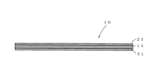
図1に示す本発明の一実施形態に係る繊維強化成形体10は、芯材11と、前記芯材11の両面に積層一体化された繊維補強材21とからなり、ノートパソコン等の携帯機器の筐体などに用いられる。前記繊維強化成形体10は、所定サイズの板状からなり、厚みが0.3〜2.0mm、曲げ弾性率(JIS K 7074−1988 A法)が30GPa以上、比重1.5以下、好ましくは1.4以下のものである。厚みが0.3mm未満では剛性が得られず、2.0mmより厚いと携帯機器全体が厚くなり適さない。なお、前記繊維強化成形体10は、携帯機器の筐体として用いられる場合、筐体の側壁等が、射出成形等のいわゆるアウトサート成形で、所定の表面位置に適宜立設される。
Hereinafter, the fiber reinforced molded product and the manufacturing method thereof of the present invention will be described with reference to the drawings.
A fiber reinforced molded body 10 according to an embodiment of the present invention shown in FIG. 1 includes a
前記芯材11は、連続気泡を有する熱硬化性樹脂発泡体に熱硬化性樹脂が含浸して前記熱硬化性樹脂発泡体を圧縮した状態で前記熱硬化性樹脂が硬化したものであって、前記式(A1)で規定される圧縮率が200〜5000%の範囲、特に好ましくは1000〜2600%のものからなる。前記圧縮率の範囲とすることにより、前記繊維強化成形体10の薄肉化と剛性の向上が図れる。
The
前記連続気泡を有する熱硬化性樹脂発泡体は、特に限定されるものではなく、例えば、ウレタン樹脂発泡体又はメラミン樹脂発泡体から選択することができる。また、前記繊維強化成形体10に難燃性が求められる場合には、前記熱硬化性樹脂発泡体としては難燃性のものが好ましく、メラミン樹脂発泡体は樹脂単体が良好な難燃性を有するため、前記熱硬化性樹脂発泡体として好適なものである。前記熱硬化性樹脂発泡体の圧縮前の元厚みは、前記圧縮率により異なるが、例えば1〜25mmを挙げる。この範囲に元厚みがあると、適度な量の熱硬化性樹脂を含浸でき、加熱圧縮後の歩留まりも良い。元厚みが1mmより薄いと、含浸した熱硬化性樹脂が保持できず、樹脂比率がばらつく為、曲げ弾性率(剛性)が低下する。元厚みが25mmより厚いと、厚さ2mm以下の繊維強化成形体を得ようとした場合、圧縮が困難で、均一な厚みの繊維強化成形体が得られない。また、前記熱硬化性樹脂発泡体は、圧縮容易性、含浸性、軽量性、剛性の点から、圧縮前の密度が5〜80kg/m3のものが好ましい。 The thermosetting resin foam having the open cells is not particularly limited, and can be selected from, for example, a urethane resin foam or a melamine resin foam. When the fiber reinforced molded body 10 is required to have flame retardancy, the thermosetting resin foam is preferably flame retardant, and the melamine resin foam has good flame retardancy when the resin alone is used. Therefore, it is suitable as the thermosetting resin foam. Although the original thickness before compression of the said thermosetting resin foam changes with the said compression rates, 1-25 mm is mentioned, for example. When the original thickness is within this range, an appropriate amount of thermosetting resin can be impregnated, and the yield after heat compression is good. When the original thickness is less than 1 mm, the impregnated thermosetting resin cannot be retained, and the resin ratio varies, so that the flexural modulus (rigidity) decreases. When the original thickness is greater than 25 mm, when trying to obtain a fiber reinforced molded product having a thickness of 2 mm or less, compression is difficult and a fiber reinforced molded product having a uniform thickness cannot be obtained. The thermosetting resin foam preferably has a density before compression of 5 to 80 kg / m 3 from the viewpoints of easy compression, impregnation, light weight and rigidity.
前記熱硬化性樹脂発泡体に含浸する熱硬化性樹脂は、特に限定されないが、前記繊維強化成形体10の剛性を高めるためには、熱硬化性樹脂自体がある程度の剛性を有する必要があり、エポキシ樹脂、フェノール樹脂、エポキシ樹脂とフェノール樹脂の混合物からなる群より選択することができる。また、前記繊維強化成形体10に難燃性が求められる場合、前記熱硬化性樹脂は難燃性のものが好ましい。フェノール樹脂は良好な難燃性を有するため、前記熱硬化性樹脂発泡体に含浸させる熱硬化性樹脂として好適なものである。 The thermosetting resin impregnated in the thermosetting resin foam is not particularly limited, but in order to increase the rigidity of the fiber-reinforced molded body 10, the thermosetting resin itself needs to have a certain degree of rigidity. It can be selected from the group consisting of epoxy resins, phenol resins, and mixtures of epoxy resins and phenol resins. When the fiber reinforced molded body 10 is required to have flame retardancy, the thermosetting resin is preferably flame retardant. Since the phenol resin has good flame retardancy, it is suitable as a thermosetting resin impregnated in the thermosetting resin foam.
前記繊維補強材21は、炭素繊維織物に熱硬化性樹脂が含浸し、硬化したものからなる。前記炭素繊維織物は、軽量及び高剛性に優れるものであり、特に、繊維が一方向のみではない織り方のものが好ましく、例えば、縦糸と横糸で構成される平織、綾織、朱子織及び3方向の糸で構成される三軸織などが好適である。また、前記炭素繊維織物は、熱硬化性樹脂の含浸及び剛性の点から、繊維重さが90〜400g/m2のものが好ましい。
The
前記炭素繊維織物に含浸する熱硬化性樹脂は、特に限定されないが、前記繊維強化成形体10の剛性を高めるためには、熱硬化性樹脂自体がある程度の剛性を有する必要があり、エポキシ樹脂、フェノール樹脂、エポキシ樹脂とフェノール樹脂の混合物からなる群より選択することができる。また、前記繊維強化成形体10に難燃性が求められる場合、前記熱硬化性樹脂は難燃性のものが好ましい。フェノール樹脂は良好な難燃性を有するため、前記炭素繊維織物に含浸させる熱硬化性樹脂として好適なものである。 The thermosetting resin impregnated in the carbon fiber fabric is not particularly limited, but in order to increase the rigidity of the fiber-reinforced molded body 10, the thermosetting resin itself needs to have a certain degree of rigidity, and an epoxy resin, It can be selected from the group consisting of phenolic resins, mixtures of epoxy resins and phenolic resins. When the fiber reinforced molded body 10 is required to have flame retardancy, the thermosetting resin is preferably flame retardant. Since the phenol resin has good flame retardancy, it is suitable as a thermosetting resin impregnated in the carbon fiber fabric.
また、前記熱硬化性樹脂は、前記式(B1)で規定される樹脂比率が50〜80%、特には55〜70%となるように前記熱硬化性樹脂発泡体及び前記炭素繊維織物に含浸させることが好ましい。前記樹脂比率とすることにより、前記繊維強化成形体10を薄肉化しても軽量性及び剛性をより良好にすることができる。
なお、前記樹脂比率の式における含浸後の重量は、熱硬化性樹脂を溶剤に溶かして使用した場合には、含浸後に乾燥させて溶剤を除去した後の重量であり、溶剤を除去した後であれば、芯材と前記補強材の一体化前あるいは一体化後の何れでもよい。
The thermosetting resin impregnates the thermosetting resin foam and the carbon fiber fabric so that the resin ratio defined by the formula (B1) is 50 to 80%, particularly 55 to 70%. It is preferable to make it. By setting it as the said resin ratio, even if it thins the said fiber reinforced molded object 10, lightness and rigidity can be made more favorable.
In addition, the weight after impregnation in the formula of the resin ratio is the weight after drying after impregnation and removing the solvent when the thermosetting resin is dissolved in the solvent, and after removing the solvent. If it exists, it may be either before or after the core material and the reinforcing material are integrated.
前記芯材11と前記繊維補強材21との一体化は、前記熱硬化性樹脂が含浸した熱硬化性樹脂発泡体と炭素繊維織物との積層体を圧縮した状態で前記熱硬化性樹脂を硬化させることによって行うことができる。前記熱硬化性樹脂発泡体に含浸した熱硬化性樹脂と前記炭素繊維織物に含浸した熱硬化性樹脂とは、同一種類でも異種類でもよいが、前記芯材11と繊維補強材21との接着性を良好にするには同一種類とするのが好ましい。
The
次に、本発明の繊維強化成形体の製造方法について説明する。繊維強化成形体の製造方法は、含浸工程、積層工程、圧縮加熱工程とからなる。
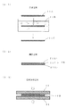
まず、第1実施形態について説明する。第1実施形態の製造方法では、図2に示す(2−1)の含浸工程において、炭素繊維織物21Aに熱硬化性樹脂21Bを含浸させ、含浸済み炭素繊維織物21Cを形成する。前記炭素繊維織物21A及び前記熱硬化性樹脂21Bは、前記繊維強化成形体10において説明したとおりである。含浸時に用いる熱硬化性樹脂21Bは、未硬化の液状からなる。また、含浸を容易にするため、前記熱硬化性樹脂21Bは溶剤に溶かしたものが好ましく、含浸後に、含浸済み炭素繊維織物21Cを前記熱硬化性樹脂の硬化反応を生じない温度で乾燥させることにより、前記含浸済み炭素繊維織物21Cから溶剤を除去する。含浸手段は、液状の熱硬化性樹脂21Bを収容した槽に前記炭素繊維織物21Aを浸ける方法、スプレーにより行う方法、ロールコータにより行う方法等、適宜の方法により行うことができる。
Next, the manufacturing method of the fiber reinforced molded object of this invention is demonstrated. The manufacturing method of a fiber reinforced molded object consists of an impregnation process, a lamination process, and a compression heating process.
First, the first embodiment will be described. In the manufacturing method according to the first embodiment, in the impregnation step (2-1) shown in FIG. 2, the carbon fiber fabric 21A is impregnated with the
前記炭素繊維織物21Aに、前記式(B1)で規定する樹脂比率が、50〜80%、特には55〜70%となるように熱硬化性樹脂21Bを含浸させることが好ましい。
なお、第1実施形態では、前記含浸工程において炭素繊維織物21Aのみに熱硬化性樹脂21Bを含浸させ、前記炭素繊維織物21Aに含浸した熱硬化性樹脂21Bが、後述のように圧縮加熱工程で前記熱硬化性樹脂発泡体11Aに含浸するため、前記樹脂比率の式(B1)における(熱硬化性樹脂含浸後の熱硬化性樹脂発泡体と炭素繊維織物の合計重量−熱硬化性樹脂含浸前の熱硬化性樹脂発泡体と炭素繊維織物の合計重量)は、含浸工程において炭素繊維織物21Aに含浸した熱硬化性樹脂21Bの重量と等しい値である。また、前記樹脂比率の式における含浸後の重量は、熱硬化性樹脂を溶剤に溶かして使用した場合には、含浸後に乾燥させて溶剤を除去した後の重量である。
The carbon fiber fabric 21A is preferably impregnated with the
In the first embodiment, in the impregnation step, only the carbon fiber fabric 21A is impregnated with the
図2に示す(2−2)の積層工程では、連続気泡を有する熱硬化性樹脂発泡体11Aの両面に、前記(2−1)の含浸工程で得られた含浸済み炭素繊維織物21Cを配置して積層体10Aとする。連続気泡を有する熱硬化性樹脂発泡体11Aは、前記繊維強化成形体10において説明したとおりである。なお、前記積層作業は、次に行う(2−3)の圧縮加熱工程で用いるプレス成形用下型31の上面に、前記含浸済み炭素繊維織物21C、前記熱硬化性樹脂発泡体11A、前記含浸済み炭素繊維織物21Cの順に重ねて行ってもよい。また、前記含浸済み炭素繊維織物21Cと連続気泡を有する熱硬化性樹脂発泡体11Aは、平面サイズが同サイズのものが好ましいが、異なっていている場合には、後述の圧縮加熱工程後にトリミングすればよい。
In the lamination step (2-2) shown in FIG. 2, the impregnated
図2に示す(2−3)の圧縮加熱工程では、前記積層体10Aをプレス成形用下型31と上型33により圧縮すると共に加熱する。圧縮は、前記繊維強化成形体10で説明した式(A1)により得られる圧縮率が200〜5000%、特に好ましくは1000〜2600%となるように調整する。なお、前記プレス成形用下型31と上型33間の間隔を変化させて繊維強化成形体を実際に製造し、得られた繊維強化成形体から圧縮率を計算して目的の圧縮率となる前記プレス成形用下型31と上型33間の間隔を見つける。前記圧縮加熱工程時、前記プレス成形用下型31と上型33間には適宜の位置にスペーサを設置して、前記プレス成形用下型31と上型33間が所定間隔(積層体の所定圧縮厚み)となるようにされる。また、積層体の加熱方法は特に限定されないが、前記プレス成形用下型31と上型33にヒータ等の加熱手段を設けて、前記プレス成形用下型31と上型33を介して加熱するのが簡単である。加熱温度は、前記含浸している熱硬化性樹脂の硬化反応温度以上とされる。
In the compression heating step (2-3) shown in FIG. 2, the
前記圧縮加熱工程時に前記積層体10Aが圧縮されると、前記積層体10Aの含浸済み炭素繊維織物21Cから熱硬化性樹脂が押し出され、前記含浸済み炭素繊維織物21Cと接している前記熱硬化性樹脂発泡体11Aに含浸し、前記積層体10Aの全体に含浸する。前記積層体10Aの全体に含浸した熱硬化性樹脂は、加熱により硬化反応を開始し、前記積層体10Aの圧縮状態、すなわち前記熱硬化性樹脂発泡体11Aが圧縮された状態で硬化する。それにより、前記熱構成樹脂発泡体11Aから前記芯材11が形成され、また、前記含浸済み炭素繊維織物21Cから前記繊維補強材21が形成され、前記芯材11と前記繊維補強材21が一体化して前記繊維強化成形体10が形成される。その後、加熱圧縮を解除して前記繊維強化成形体10を得る。
When the laminate 10A is compressed during the compression heating step, the thermosetting resin is extruded from the impregnated
製造方法の第2実施形態では、図3に示す(3−1)の含浸工程において、連続気泡を有する熱硬化性樹脂発泡体11Aに熱硬化性樹脂11Bを含浸させ、含浸済み熱硬化性樹脂発泡体11Cを形成する。前記連続気泡を有する熱硬化性樹脂発泡体11A及び前記熱硬化性樹脂11Bは、前記繊維強化成形体10において説明したとおりである。含浸時に用いる熱硬化性樹脂11Bは、未硬化の液状からなる。また、含浸を容易にするため、前記熱硬化性樹脂11Bは溶剤に溶かしたものが好ましく、含浸後に、含浸済み熱硬化性樹脂発泡体11Cを前記熱硬化性樹脂の硬化反応を生じない温度で乾燥させて含浸済み熱硬化性樹脂発泡体11Cから溶剤を除去する。含浸手段は、液状の熱硬化性樹脂11Bを収容した槽に前記熱硬化性樹脂発泡体11Aを浸ける方法、スプレーにより行う方法、ロールコータにより行う方法等、適宜の方法により行う。
In the second embodiment of the manufacturing method, in the impregnation step (3-1) shown in FIG. 3, the
前記熱硬化性樹脂発泡体11Aに、前記式(B1)で規定する樹脂比率が、50〜80%、特には55〜70%となるように前記熱硬化性樹脂11Bを含浸させることが好ましい。
なお、第2実施形態では、前記含浸工程において熱硬化性樹脂発泡体11Aのみに熱硬化性樹脂11Bを含浸させ、前記熱硬化性樹脂発泡体11Aに含浸した熱硬化性樹脂11Bが、後述するように圧縮加熱工程で前記炭素繊維織物21Aに含浸するため、前記樹脂比率の式(B1)における(熱硬化性樹脂含浸後の熱硬化性樹脂発泡体と炭素繊維織物の合計重量−熱硬化性樹脂含浸前の熱硬化性樹脂発泡体と炭素繊維織物の合計重量)は、含浸工程において熱硬化性樹脂発泡体11Aに含浸した熱硬化性樹脂11Bの重量と等しい値である。また、前記樹脂比率の式における含浸後の重量は、熱硬化性樹脂を溶剤に溶かして使用した場合には、含浸後に乾燥させて溶剤を除去した後の重量である。
The
In the second embodiment, only the
図3に示す(3−2)の積層工程では、前記含浸済み熱硬化性樹脂発泡体11Cの両面に、炭素繊維織物21Aを配置して積層体10Bを得る。前記炭素繊維織物21Aは、前記繊維強化成形体10において説明したとおりである。なお、前記積層作業は、次に行う(3−3)の圧縮加熱工程で用いるプレス成形用下型31の上面に、前記炭素繊維織物21A、前記含浸済み熱硬化性樹脂発泡体11C、前記炭素繊維織物21Aの順に重ねて行ってもよい。また、前記含浸済み熱硬化性樹脂発泡体11Cと炭素繊維織物21Aは、平面サイズが同サイズのものが好ましいが、異なっていている場合には、後述の圧縮加熱工程、最終的にトリミングすればよい。 In the layering step (3-2) shown in FIG. 3, the carbon fiber fabric 21A is disposed on both surfaces of the impregnated thermosetting resin foam 11C to obtain a laminate 10B. The carbon fiber fabric 21A is as described in the fiber reinforced molded body 10. The laminating operation is performed on the upper surface of the press molding lower mold 31 used in the compression heating step (3-3) to be performed next, the carbon fiber fabric 21A, the impregnated thermosetting resin foam 11C, and the carbon. You may superimpose in order of fiber fabric 21A. In addition, the impregnated thermosetting resin foam 11C and the carbon fiber fabric 21A preferably have the same plane size, but if they are different, if they are different from each other, the compression heating step described later, and finally trimming Good.
図3に示す(3−3)の圧縮加熱工程では、前記積層体10Bをプレス成形用下型31と上型33により、圧縮すると共に加熱する。圧縮は、前記繊維強化成形体10で説明した式(A1)により得られる圧縮率が200〜5000%、特に好ましくは1000〜2600%となるようにされる。なお、第1実施形態と同様に、前記プレス成形用下型31と上型33間の間隔を変化させて繊維強化成形体を実際に製造し、得られた繊維強化成形体から圧縮率を計算して目的の圧縮率となる前記プレス成形用下型31と上型33間の間隔を見つける。前記圧縮加熱工程時、前記プレス成形用下型31と上型33間には適宜の位置にスペーサを設置して、前記プレス成形用下型31と上型33間が所定間隔(積層体の所定圧縮厚み)となるようにされる。また、積層体の加熱方法は特に限定されないが、前記プレス成形用下型31と上型33にヒータ等の加熱手段を設けて、前記プレス成形用下型31と上型33を介して行うのが簡単である。加熱温度は、前記含浸している熱硬化性樹脂の硬化反応温度以上とされる。 In the compression heating step (3-3) shown in FIG. 3, the laminate 10B is compressed and heated by the press mold lower mold 31 and the upper mold 33. The compression is performed so that the compression ratio obtained by the formula (A1) described in the fiber reinforced molded body 10 is 200 to 5000%, particularly preferably 1000 to 2600%. As in the first embodiment, a fiber-reinforced molded body is actually manufactured by changing the interval between the press-molding lower mold 31 and the upper mold 33, and the compression rate is calculated from the obtained fiber-reinforced molded body. Thus, the distance between the lower mold 31 for press molding and the upper mold 33 that provides the desired compression ratio is found. During the compression heating step, a spacer is installed at an appropriate position between the press molding lower mold 31 and the upper mold 33, and a predetermined interval (predetermined of the laminate) is provided between the press molding lower mold 31 and the upper mold 33. Compression thickness). Further, the heating method of the laminate is not particularly limited, and heating means such as a heater is provided in the press molding lower mold 31 and the upper mold 33, and the heating is performed via the press molding lower mold 31 and the upper mold 33. Is simple. The heating temperature is set to be equal to or higher than the curing reaction temperature of the impregnated thermosetting resin.
前記圧縮加熱工程時に前記積層体10Bが圧縮されると、前記積層体10Bの含浸済み熱硬化性樹脂発泡体11Cから熱硬化性樹脂が押し出され、前記含浸済み熱硬化性樹脂発泡体11Cと接している炭素繊維織物21Aに含浸し、前記積層体10Bの全体に含浸する。前記積層体10Bの全体に含浸した熱硬化性樹脂は、加熱により硬化反応を開始し、前記積層体10Bの圧縮状態、すなわち前記含浸済み熱硬化性樹脂発泡体11Cが圧縮された状態で硬化する。それにより、前記含浸済み熱構成樹脂発泡体11Cから前記芯材11が形成され、また、前記炭素繊維織物21Aから前記繊維補強材21が形成され、前記芯材11と前記繊維補強材21が一体化して前記繊維強化成形体10が形成される。その後、加熱圧縮を解除して前記繊維強化成形体10を得る。
When the laminate 10B is compressed during the compression heating step, a thermosetting resin is extruded from the impregnated thermosetting resin foam 11C of the laminate 10B and comes into contact with the impregnated thermosetting resin foam 11C. The carbon fiber fabric 21A is impregnated to impregnate the entire laminate 10B. The thermosetting resin impregnated in the entire laminate 10B starts a curing reaction by heating, and is cured in a compressed state of the laminate 10B, that is, in a state where the impregnated thermosetting resin foam 11C is compressed. . As a result, the
製造方法の第3実施形態では、含浸工程が含浸工程Aと含浸工程Bの2種類の含浸工程からなる。
図4に示す(4−1)のように、含浸工程Aでは、連続気泡を有する熱硬化性樹脂発泡体11Aに熱硬化性樹脂11B(請求項9の熱硬化性樹脂Aに相当)を含浸させ、含浸済み熱硬化性樹脂発泡体11Cを得る。一方、含浸工程Bでは、炭素繊維織物21Aに熱硬化性樹脂21B(請求項9における熱硬化性樹脂Bに相当)を含浸させ、含浸済み炭素繊維織物21Cを形成する。前記連続気泡を有する熱硬化性樹脂発泡体11A、前記熱硬化性樹脂11B、前記炭素繊維織物21A、前記熱硬化性樹脂21Bは、前記繊維強化成形体10において説明したとおりである。含浸時に用いる熱硬化性樹脂11B,21Bは、未硬化の液状からなる。また、含浸を容易にするため、前記熱硬化性樹脂11B,21Bは溶剤に溶かしたものが好ましく、含浸後に、含浸済み熱硬化性樹脂発泡体11C及び含浸済み炭素繊維織物21Cを、前記熱硬化性樹脂の硬化反応を生じない温度で乾燥させて含浸済み熱硬化性樹脂発泡体11C及び含浸済み炭素繊維織物21Cから溶剤を除去する。含浸手段は、液状の熱硬化性樹脂を収容した槽に前記熱硬化性樹脂発泡体あるいは炭素繊維織物を浸ける方法、スプレーにより行う方法、ロールコータにより行う方法等、適宜の方法により行う。
In the third embodiment of the manufacturing method, the impregnation step includes two types of impregnation steps, impregnation step A and impregnation step B.
As in (4-1) shown in FIG. 4, in the impregnation step A, the
前記熱硬化性樹脂発泡体11Aへの前記熱硬化性樹脂11Bの含浸と、前記炭素繊維織物21Aへの熱硬化性樹脂21Bの含浸は、前記式(B1)で規定される樹脂比率が、50〜80%、特には55〜70%となるように含浸させることが好ましい。
第3実施形態では、前記熱硬化性樹脂発泡体11Aに含浸した熱硬化性樹脂11Bの重量と前記炭素繊維織物21Aに含浸した熱硬化性樹脂21Bの重量の合計は、前記樹脂比率の式(B1)における(熱硬化性樹脂含浸後の熱硬化性樹脂発泡体と炭素繊維織物の合計重量−熱硬化性樹脂含浸前の熱硬化性樹脂発泡体と炭素繊維織物の合計重量)と等しい値である。なお、前記樹脂比率の式における含浸後の重量は、熱硬化性樹脂を溶剤に溶かして使用した場合には、含浸後に乾燥させて溶剤を除去した後の重量である。
The impregnation of the thermosetting resin 11B into the
In the third embodiment, the sum of the weight of the thermosetting resin 11B impregnated in the
図4に示す(4−2)の積層工程では、前記含浸済み熱硬化性樹脂発泡体11Cの両面に、前記含浸済み炭素繊維織物21Cを配置して積層体10Cとする。なお、前記積層作業は、次に行う(4−3)の圧縮加熱工程で用いるプレス成形用下型31の上面に、前記含浸済み炭素繊維織物21C、前記含浸済み熱硬化性樹脂発泡体11C、前記含浸済み炭素繊維織物21Cの順に重ねて行ってもよい。また、前記含浸済み熱硬化性樹脂発泡体11Cと含浸済み炭素繊維織物21Cは、平面サイズが同サイズのものが好ましいが、異なっていている場合には、後述の圧縮加熱工程後、最終的にトリミングすればよい。
In the laminating step (4-2) shown in FIG. 4, the impregnated
図4に示す(4−3)の圧縮加熱工程では、前記積層体10Cをプレス成形用下型31と上型33により、圧縮すると共に加熱する。圧縮は、前記繊維強化成形体10で説明した式(A1)により得られる圧縮率が200〜5000%、特に好ましくは1000〜2600%となるようにする。なお、第1実施形態及び第2実施形態と同様に、前記プレス成形用下型31と上型33間の間隔を変化させて繊維強化成形体を実際に製造し、得られた繊維強化成形体から圧縮率を計算して目的の圧縮率となる前記プレス成形用下型31と上型33間の間隔を見つける。前記圧縮加熱工程時、前記プレス成形用下型31と上型33間には適宜の位置にスペーサを設置して、前記プレス成形用下型31と上型33間が所定間隔(積層体の所定圧縮厚み)となるようにされる。また、加熱方法は特に限定されないが、前記プレス成形用下型31と上型33にヒータ等の加熱手段を設けて、前記プレス成形用下型31と上型33を介して行うのが簡単である。加熱温度は、前記含浸している熱硬化性樹脂の硬化反応温度以上とされる。 In the compression heating step (4-3) shown in FIG. 4, the laminate 10 </ b> C is compressed and heated by the press mold lower mold 31 and the upper mold 33. The compression is performed so that the compression ratio obtained by the formula (A1) described in the fiber reinforced molded body 10 is 200 to 5000%, particularly preferably 1000 to 2600%. Similar to the first embodiment and the second embodiment, the fiber-reinforced molded body obtained by actually manufacturing the fiber-reinforced molded body by changing the interval between the lower mold 31 for press molding and the upper mold 33 was obtained. The compression ratio is calculated from the above, and the interval between the lower mold 31 for press molding and the upper mold 33 that finds the target compression ratio is found. During the compression heating step, a spacer is installed at an appropriate position between the press molding lower mold 31 and the upper mold 33, and a predetermined interval (predetermined of the laminate) is provided between the press molding lower mold 31 and the upper mold 33. Compression thickness). The heating method is not particularly limited, and it is easy to perform heating via the press molding lower mold 31 and the upper mold 33 by providing heating means such as a heater in the press molding lower mold 31 and the upper mold 33. is there. The heating temperature is set to be equal to or higher than the curing reaction temperature of the impregnated thermosetting resin.
前記圧縮加熱工程における圧縮により、前記含浸済み炭素繊維織物21Cの熱硬化性樹脂と前記含浸済み熱硬化性樹脂発泡体11Cの熱硬化性樹脂が確実に接触する。そして前記圧縮加熱工程における加熱により、前記含浸済み熱硬化性樹脂発泡体11Cの熱硬化性樹脂と前記含浸済み炭素繊維織物21Cの熱硬化性樹脂が硬化反応を開始し、前記積層体10Cの圧縮状態、すなわち前記含浸済み熱硬化性樹脂発泡体11Cが圧縮された状態で硬化する。それにより、前記含浸済み熱構成樹脂発泡体11Cから前記芯材11が形成され、また、前記含浸済み炭素繊維織物21Cから前記繊維補強材21が形成され、前記芯材11と前記繊維補強材21が一体化して前記繊維強化成形体10が形成される。その後、加熱圧縮を解除して前記繊維強化成形体10を得る。
By the compression in the compression heating step, the thermosetting resin of the impregnated
・実施例1
熱硬化性樹脂としてフェノール樹脂(旭有機材料株式会社製、品名;PAPS−4と旭有機材料株式会社製、品名;ヘキサメチレンテトラミンを100:12で混合したもの)をメタノールに30wt%の濃度となるように溶解した。このフェノール樹脂溶液中に平織の炭素繊維織物(東邦テナックス株式会社製、品名;W−3101、繊維重さ200g/m2)を漬け、取り出した後に25℃の室温にて2時間自然乾燥し、更に60℃の雰囲気下にて1時間乾燥させて含浸済み炭素繊維織物を2枚形成した。炭素繊維織物は、200×300mmの平面サイズに裁断したもの(重量12g/枚)を使用した。乾燥後の含浸済み炭素繊維織物は1枚あたり28gであった。
Example 1
As a thermosetting resin, phenol resin (Asahi Organic Materials Co., Ltd., product name: PAPS-4 and Asahi Organic Materials Co., Ltd., product name: hexamethylenetetramine mixed at 100: 12) in methanol with a concentration of 30 wt% It dissolved so that it might become. A plain-woven carbon fiber woven fabric (manufactured by Toho Tenax Co., Ltd., product name: W-3101, fiber weight 200 g / m 2 ) is dipped in this phenol resin solution, taken out and air-dried at room temperature of 25 ° C. for 2 hours, Further, it was dried in an atmosphere at 60 ° C. for 1 hour to form two impregnated carbon fiber fabrics. The carbon fiber fabric used was cut into a plane size of 200 × 300 mm (weight 12 g / sheet). The impregnated carbon fiber fabric after drying was 28 g per sheet.
また、連続気泡を有する熱硬化性樹脂発泡体として、厚み10mm、平面サイズ200×300mm(重量5.4g)に切り出したメラミン樹脂発泡体(BASF社製、品名:バソテクトV3012、密度9kg/m3)を、炭素繊維織物と同様にしてフェノール樹脂溶液に漬け、取り出した後に25℃の室温にて2時間自然乾燥し、更に60℃の雰囲気下にて1時間乾燥させて含浸済み熱硬化性樹脂発泡体を形成した。乾燥後の含浸済み熱硬化樹脂発泡体の重量は27gであった。また、炭素繊維織物と熱硬化性発泡体全体に含まれる樹脂比率(前記樹脂比率の式(B1)で計算した値)は65%であった。 Moreover, as a thermosetting resin foam having open cells, a melamine resin foam cut out to a thickness of 10 mm and a plane size of 200 × 300 mm (weight 5.4 g) (manufactured by BASF, product name: Vasotect V3012, density 9 kg / m 3 ) Is immersed in a phenolic resin solution in the same manner as the carbon fiber fabric, taken out, dried naturally at room temperature of 25 ° C. for 2 hours, and further dried for 1 hour in an atmosphere of 60 ° C. A foam was formed. The weight of the impregnated thermosetting resin foam after drying was 27 g. Moreover, the resin ratio (value calculated by the formula (B1) of the resin ratio) contained in the entire carbon fiber fabric and the thermosetting foam was 65%.
次に、予め離型剤を表面に塗布したSUS製のプレス成形用の下型(平板状)の上に、含浸済み炭素繊維織物、含浸済み熱硬化性樹脂発泡体、含浸済み炭素繊維織物の順に重ねて配置することにより、含浸済み熱硬化性樹脂発泡体の両面に含浸済み炭素繊維織物を配置した積層体をプレス成形用下型上にセットした。その状態で、プレス成形用下型上の積層体を、180℃で3分間、5MPaの面圧をかけてプレス成形用上型(平板状)で押圧し、圧縮及び加熱を行ない、前記圧縮状態でフェノール樹脂を反応硬化させた。その際の成形体の加熱は、上下のプレス型に取り付けられた鋳込みヒーターにより行なった。また、プレス成形用下型と上型間には厚み0.9mmのSUS製スペーサを介在させて下型と上型間の間隔、すなわち積層体の圧縮厚みを調整した。その後、プレス成形用下型と上型を室温で冷却させた後に下型と上型を開き、芯材の両面に繊維補強材が積層一体化した繊維強化成形体を得た。この繊維強化成形体を170×260mmにトリミングして実施例1の繊維強化成形体とした。 Next, an impregnated carbon fiber fabric, an impregnated thermosetting resin foam, and an impregnated carbon fiber fabric are placed on the lower mold (flat plate) for press molding made of SUS with a release agent applied on the surface in advance. By laminating in order, a laminate in which the impregnated carbon fiber fabric was disposed on both surfaces of the impregnated thermosetting resin foam was set on the lower mold for press molding. In that state, the laminated body on the lower mold for press molding is pressed with the upper mold for press molding (flat plate shape) at 180 ° C. for 3 minutes, applying a surface pressure of 5 MPa, and compressed and heated. The phenolic resin was reacted and cured. At that time, the molded body was heated by a casting heater attached to the upper and lower press dies. Further, a 0.9 mm thick SUS spacer was interposed between the lower mold for press molding and the upper mold to adjust the distance between the lower mold and the upper mold, that is, the compression thickness of the laminate. Thereafter, the lower mold and the upper mold for press molding were cooled at room temperature, and then the lower mold and the upper mold were opened to obtain a fiber reinforced molded body in which fiber reinforcing materials were laminated and integrated on both surfaces of the core material. This fiber reinforced molded body was trimmed to 170 × 260 mm to obtain a fiber reinforced molded body of Example 1.
実施例1の繊維強化成形体について、比重、全体の厚み及び芯材の厚みを測定した。比重は1.30、全体の厚みは0.89mm、芯材の厚みは0.43mmであった。芯材を構成する熱硬化性樹脂発泡体の圧縮率は、前記圧縮前の熱硬化性樹脂発泡体の厚み(10mm)と前記芯材の厚み(0.43mm)を用い、前記圧縮率の式に従って計算すると2225%であった。また、実施例1の繊維強化成形体について、剛性を判断するために曲げ弾性率(JIS K7074−1988 A法)を測定した。測定結果は、曲げ弾性率が50GPa(繊維方向)であった。 About the fiber reinforced molded object of Example 1, specific gravity, the whole thickness, and the thickness of the core material were measured. The specific gravity was 1.30, the total thickness was 0.89 mm, and the thickness of the core material was 0.43 mm. The compression rate of the thermosetting resin foam constituting the core material is obtained by using the thickness of the thermosetting resin foam before compression (10 mm) and the thickness of the core material (0.43 mm), and the expression of the compression rate. Was calculated to be 2225%. Further, the flexural modulus (JIS K7074-1988 A method) of the fiber reinforced molded body of Example 1 was measured in order to determine the rigidity. As a result of the measurement, the flexural modulus was 50 GPa (fiber direction).
・実施例2
連続気泡を有する熱硬化性樹脂発泡体の厚みを5mmとし、熱硬化性樹脂発泡体への熱硬化性樹脂の含浸量を調整して、炭素繊維織物と熱硬化性発泡体全体に含まれる樹脂比率(前記樹脂比率の式(B1)で計算した値)を65%とした以外は、実施例1と同様にして、繊維強化成形体を得た。
実施例2の繊維強化成形体について、比重、全体の厚み及び芯材の厚みを測定した。比重は1.29、全体の厚みは0.89mm、芯材の厚みは0.43mmであった。芯材を構成する熱硬化性樹脂発泡体の圧縮率は、前記圧縮前の熱硬化性樹脂発泡体の厚み(5mm)と前記芯材の厚み(0.43mm)を用い、前記圧縮率の式に従って計算すると1062%であった。また、実施例2の繊維強化成形体について、剛性を判断するために曲げ弾性率(JIS K7074−1988 A法)を測定した。測定結果は曲げ弾性率が49GPa(繊維方向)であった。
Example 2
Resin contained in the carbon fiber fabric and the entire thermosetting foam by adjusting the amount of the thermosetting resin impregnated into the thermosetting resin foam by adjusting the thickness of the thermosetting resin foam having open cells to 5 mm. A fiber-reinforced molded body was obtained in the same manner as in Example 1 except that the ratio (value calculated by the formula (B1) of the resin ratio) was 65%.
About the fiber reinforced molded object of Example 2, specific gravity, the whole thickness, and the thickness of the core material were measured. The specific gravity was 1.29, the overall thickness was 0.89 mm, and the thickness of the core material was 0.43 mm. The compression rate of the thermosetting resin foam constituting the core material is obtained by using the thickness of the thermosetting resin foam before compression (5 mm) and the thickness of the core material (0.43 mm), and the expression of the compression rate. Calculated to be 1062%. Further, the flexural modulus (JIS K7074-1988 A method) of the fiber reinforced molded body of Example 2 was measured in order to determine the rigidity. The measurement result was a flexural modulus of 49 GPa (fiber direction).
・実施例3
連続気泡を有する熱硬化性樹脂発泡体の厚みを11.5mmとし、熱硬化性樹脂発泡体への熱硬化性樹脂の含浸量を調整して、炭素繊維織物と熱硬化性発泡体全体に含まれる樹脂比率(前記樹脂比率の式(B1)で計算した値)を65%とした以外は、実施例1と同様にして、繊維強化成形体を得た。実施例3の繊維強化成形体について、比重、全体の厚み及び芯材の厚みを測定した。比重は1.32、全体の厚みは0.9mm、芯材の厚みは0.44mmであった。芯材を構成する熱硬化性樹脂発泡体の圧縮率は、前記圧縮前の熱硬化性樹脂発泡体の厚み(11.5mm)と前記芯材の厚み(0.44mm)を用い、前記圧縮率の式に従って計算すると2513%であった。また、実施例3の繊維強化成形体について、剛性を判断するために曲げ弾性率(JIS K7074−1988 A法)を測定した。測定結果は曲げ弾性率が51GPa(繊維方向)であった。
Example 3
The thickness of the thermosetting resin foam having open cells is 11.5 mm, and the amount of the thermosetting resin impregnated into the thermosetting resin foam is adjusted to be included in the entire carbon fiber fabric and the thermosetting foam. A fiber-reinforced molded body was obtained in the same manner as in Example 1 except that the resin ratio (value calculated by the formula (B1) of the resin ratio) was 65%. About the fiber reinforced molded object of Example 3, specific gravity, the whole thickness, and the thickness of the core material were measured. The specific gravity was 1.32, the overall thickness was 0.9 mm, and the core material thickness was 0.44 mm. The compression rate of the thermosetting resin foam constituting the core material is determined by using the thickness (11.5 mm) of the thermosetting resin foam before compression and the thickness (0.44 mm) of the core material. It was 25133% when calculated according to the formula of Further, the flexural modulus (JIS K7074-1988 A method) of the fiber reinforced molded body of Example 3 was measured in order to determine the rigidity. The measurement result was a flexural modulus of 51 GPa (fiber direction).
・実施例4
連続気泡を有する熱硬化性樹脂発泡体の厚みを1.4mmとし、熱硬化性樹脂発泡体への熱硬化性樹脂の含浸量を調整して、炭素繊維織物と熱硬化性発泡体全体に含まれる樹脂比率(前記樹脂比率の式(B1)で計算した値)を65%とした以外は、実施例1と同様にして、繊維強化成形体を得た。実施例4の繊維強化成形体について、比重、全体の厚み及び芯材の厚みを測定した。比重は1.28、全体の厚みは0.89mm、芯材の厚みは0.43mmであった。芯材を構成する熱硬化性樹脂発泡体の圧縮率は、前記圧縮前の熱硬化性樹脂発泡体の厚み(1.4mm)と前記芯材の厚み(0.43mm)を用い、前記圧縮率の式に従って計算すると225%であった。また、実施例4の繊維強化成形体について、剛性を判断するために曲げ弾性率(JIS K7074−1988 A法)を測定した。測定結果は曲げ弾性率が46GPa(繊維方向)であった。
Example 4
The thickness of the thermosetting resin foam with open cells is 1.4mm, and the amount of thermosetting resin impregnated into the thermosetting resin foam is adjusted to be included in the entire carbon fiber fabric and thermosetting foam. A fiber-reinforced molded body was obtained in the same manner as in Example 1 except that the resin ratio (value calculated by the formula (B1) of the resin ratio) was 65%. About the fiber reinforced molded object of Example 4, specific gravity, the whole thickness, and the thickness of the core material were measured. The specific gravity was 1.28, the overall thickness was 0.89 mm, and the thickness of the core material was 0.43 mm. The compression rate of the thermosetting resin foam constituting the core material is determined by using the thickness (1.4 mm) of the thermosetting resin foam before compression and the thickness (0.43 mm) of the core material. It was 225% when calculated according to the formula of Further, the flexural modulus (JIS K7074-1988 A method) of the fiber reinforced molded body of Example 4 was measured in order to determine the rigidity. The measurement result was a flexural modulus of 46 GPa (fiber direction).
・実施例5
連続気泡を有する熱硬化性樹脂発泡体の厚みを22mmとし、熱硬化性樹脂発泡体への熱硬化性樹脂の含浸量を調整して、炭素繊維織物と熱硬化性発泡体全体に含まれる樹脂比率(前記樹脂比率の式(B1)で計算した値)を65%とした以外は、実施例1と同様にして、繊維強化成形体を得た。実施例5の繊維強化成形体について、比重、全体の厚み及び芯材の厚みを測定した。比重は1.35、全体の厚みは0.9mm、芯材の厚みは0.44mmであった。芯材を構成する熱硬化性樹脂発泡体の圧縮率は、前記圧縮前の熱硬化性樹脂発泡体の厚み(22mm)と前記芯材の厚み(0.44mm)を用い、前記圧縮率の式に従って計算すると4900%であった。また、実施例5の繊維強化成形体について、剛性を判断するために曲げ弾性率(JIS K7074−1988 A法)を測定した。測定結果は曲げ弾性率が51GPa(繊維方向)であった。
Example 5
Resin contained in the entire carbon fiber fabric and the thermosetting foam by adjusting the amount of the thermosetting resin impregnated into the thermosetting resin foam by adjusting the thickness of the thermosetting resin foam having open cells to 22 mm. A fiber-reinforced molded body was obtained in the same manner as in Example 1 except that the ratio (value calculated by the formula (B1) of the resin ratio) was 65%. About the fiber reinforced molded object of Example 5, specific gravity, the whole thickness, and the thickness of the core material were measured. The specific gravity was 1.35, the overall thickness was 0.9 mm, and the core material thickness was 0.44 mm. The compression rate of the thermosetting resin foam constituting the core material is obtained by using the thickness of the thermosetting resin foam before compression (22 mm) and the thickness of the core material (0.44 mm), and the compression rate formula It was 4900% when calculated according to the above. Further, the flexural modulus (JIS K7074-1988 A method) of the fiber reinforced molded body of Example 5 was measured in order to determine the rigidity. The measurement result was a flexural modulus of 51 GPa (fiber direction).
・実施例6
乾燥後の含浸済み炭素繊維織物の重量が1枚あたり35gであり、乾燥後の含浸済み熱硬化樹脂発泡体の重量が45gであり、炭素繊維織物と熱硬化性発泡体全体に含まれる樹脂比率(前記樹脂比率の式(B1)で計算した値)を74%とした以外は、実施例1と同様にして、繊維強化成形体を得た。実施例6の繊維強化成形体について、比重、全体の厚み及び芯材の厚みを測定した。比重は1.45、全体の厚みは0.98mm、芯材の厚みは0.52mmであった。芯材を構成する熱硬化性樹脂発泡体の圧縮率は、前記圧縮前の熱硬化性樹脂発泡体の厚み(10mm)と前記芯材の厚み(0.52mm)を用い、前記圧縮率の式に従って計算すると1823%であった。また、実施例6の繊維強化成形体について、剛性を判断するために曲げ弾性率(JIS K 7074−1988 A法)を測定した。測定結果は曲げ弾性率が55GPa(繊維方向)であった。
Example 6
The weight of the impregnated carbon fiber fabric after drying is 35 g per sheet, the weight of the impregnated thermosetting resin foam after drying is 45 g, and the resin ratio contained in the entire carbon fiber fabric and the thermosetting foam. A fiber-reinforced molded body was obtained in the same manner as in Example 1 except that (the value calculated by the formula (B1) of the resin ratio) was 74%. About the fiber reinforced molded object of Example 6, specific gravity, the whole thickness, and the thickness of the core material were measured. The specific gravity was 1.45, the overall thickness was 0.98 mm, and the thickness of the core material was 0.52 mm. The compression rate of the thermosetting resin foam constituting the core material is obtained by using the thickness of the thermosetting resin foam before compression (10 mm) and the thickness of the core material (0.52 mm), and the compression rate formula And calculated according to 182. Moreover, in order to judge rigidity about the fiber reinforced molded object of Example 6, the bending elastic modulus (JIS K7074-1988 A method) was measured. The measurement result was a flexural modulus of 55 GPa (fiber direction).
・実施例7
乾燥後の含浸済み炭素繊維織物の重量が1枚あたり22gであり、乾燥後の含浸済み熱硬化樹脂発泡体の重量が16gであり、炭素繊維織物と熱硬化性発泡体全体に含まれる樹脂比率(前記樹脂比率の式(B1)で計算した値)を51%とした以外は、実施例1と同様にして、繊維強化成形体を得た。実施例7の繊維強化成形体について、比重、全体の厚み及び芯材の厚みを測定した。比重は1.30、全体の厚みは0.89mm、芯材の厚みは0.43mmであった。芯材を構成する熱硬化性樹脂発泡体の圧縮率は、前記圧縮前の熱硬化性樹脂発泡体の厚み(10mm)と前記芯材の厚み(0.43mm)を用い、前記圧縮率の式に従って計算すると2225%であった。また、実施例7の繊維強化成形体について、剛性を判断するために曲げ弾性率(JIS K7074−1988 A法)を測定した。測定結果は曲げ弾性率が45GPa(繊維方向)であった。
-Example 7
The weight of the impregnated carbon fiber fabric after drying is 22 g per sheet, the weight of the impregnated thermosetting resin foam after drying is 16 g, and the resin ratio contained in the entire carbon fiber fabric and the thermosetting foam. A fiber-reinforced molded body was obtained in the same manner as in Example 1 except that the value (calculated by the formula (B1) of the resin ratio) was 51%. About the fiber reinforced molded object of Example 7, specific gravity, the whole thickness, and the thickness of the core material were measured. The specific gravity was 1.30, the total thickness was 0.89 mm, and the thickness of the core material was 0.43 mm. The compression rate of the thermosetting resin foam constituting the core material is obtained by using the thickness of the thermosetting resin foam before compression (10 mm) and the thickness of the core material (0.43 mm), and the expression of the compression rate. Was calculated to be 2225%. In addition, the flexural modulus (JIS K7074-1988 A method) of the fiber-reinforced molded body of Example 7 was measured in order to determine rigidity. The measurement result was a flexural modulus of 45 GPa (fiber direction).
・実施例8
乾燥後の含浸済み炭素繊維織物の重量が40gであり、熱硬化樹脂発泡体には樹脂を含浸させずに、炭素繊維織物と熱硬化性発泡体全体に含まれる樹脂比率(前記樹脂比率の式(B1)で計算した値)を66%とした以外は、実施例1と同様にして、繊維強化成形体を得た。実施例8の繊維強化成形体について、比重、全体の厚み及び芯材の厚みを測定した。比重は1.30、全体の厚みは0.89mm、芯材の厚みは0.43mmであった。芯材を構成する熱硬化性樹脂発泡体の圧縮率は、前記圧縮前の熱硬化性樹脂発泡体の厚み(10mm)と前記芯材の厚み(0.43mm)を用い、前記圧縮率の式に従って計算すると2225%であった。また、実施例8の繊維強化成形体について、剛性を判断するために曲げ弾性率(JIS K7074−1988 A法)を測定した。測定結果は曲げ弾性率が50GPa(繊維方向)であった。
Example 8
The weight of the impregnated carbon fiber fabric after drying is 40 g, and the resin ratio contained in the entire carbon fiber fabric and the thermosetting foam without impregnating the resin in the thermosetting resin foam (the formula of the resin ratio) A fiber-reinforced molded body was obtained in the same manner as in Example 1 except that the value calculated in (B1) was 66%. About the fiber reinforced molded object of Example 8, specific gravity, the whole thickness, and the thickness of the core material were measured. The specific gravity was 1.30, the total thickness was 0.89 mm, and the thickness of the core material was 0.43 mm. The compression rate of the thermosetting resin foam constituting the core material is obtained by using the thickness of the thermosetting resin foam before compression (10 mm) and the thickness of the core material (0.43 mm), and the expression of the compression rate. Was calculated to be 2225%. Further, the flexural modulus (JIS K7074-1988 A method) of the fiber-reinforced molded body of Example 8 was measured in order to determine the rigidity. The measurement result was a flexural modulus of 50 GPa (fiber direction).
・実施例9
炭素繊維織物には樹脂を含浸せず、乾燥後の含浸済み熱硬化樹脂発泡体の重量が40gであり、炭素繊維織物と熱硬化性発泡体全体に含まれる樹脂比率(前記樹脂比率の式(B1)で計算した値)を54%とした以外は、実施例1と同様にして、繊維強化成形体を得た。実施例9の繊維強化成形体について、比重、全体の厚み及び芯材の厚みを測定した。比重は1.30、全体の厚みは0.89mm、芯材の厚みは0.43mmであった。芯材を構成する熱硬化性樹脂発泡体の圧縮率は、前記圧縮前の熱硬化性樹脂発泡体の厚み(10mm)と前記芯材の厚み(0.43mm)を用い、前記圧縮率の式に従って計算すると2225%であった。また、実施例9の繊維強化成形体について、剛性を判断するために曲げ弾性率(JIS K7074−1988 A法)を測定した。測定結果は曲げ弾性率が46GPa(繊維方向)であった。
Example 9
The carbon fiber fabric is not impregnated with resin, and the weight of the impregnated thermosetting resin foam after drying is 40 g, and the resin ratio contained in the entire carbon fiber fabric and the thermosetting foam (the formula of the resin ratio ( A fiber-reinforced molded body was obtained in the same manner as in Example 1 except that the value calculated in B1) was 54%. About the fiber reinforced molded object of Example 9, specific gravity, the whole thickness, and the thickness of the core material were measured. The specific gravity was 1.30, the total thickness was 0.89 mm, and the thickness of the core material was 0.43 mm. The compression rate of the thermosetting resin foam constituting the core material is obtained by using the thickness of the thermosetting resin foam before compression (10 mm) and the thickness of the core material (0.43 mm), and the expression of the compression rate. Was calculated to be 2225%. In addition, the flexural modulus (JIS K7074-1988 A method) of the fiber reinforced molded body of Example 9 was measured in order to determine rigidity. The measurement result was a flexural modulus of 46 GPa (fiber direction).
・実施例10
連続気泡を有する熱硬化性樹脂発泡体としてウレタン樹脂発泡体(株式会社イノアックコーポレーション製モルトプレンMF80、密度72kg/m3)を用い、熱硬化性樹脂発泡体への熱硬化性樹脂の含浸量を調整して、炭素繊維織物と熱硬化性発泡体全体に含まれる樹脂比率(前記樹脂比率の式(B1)で計算した値)を65%とした以外は、実施例1と同様にして、繊維強化成形体を得た。実施例10の繊維強化成形体について、比重、全体の厚み及び芯材の厚みを測定した。比重は1.35、全体の厚みは0.9mm、芯材の厚みは0.44mmであった。芯材を構成する熱硬化性樹脂発泡体の圧縮率は、前記圧縮前の熱硬化性樹脂発泡体の厚み(10mm)と前記芯材の厚み(0.44mm)を用い、前記圧縮率の式に従って計算すると2172%であった。また、実施例10の繊維強化成形体について、剛性を判断するために曲げ弾性率(JIS K7074−1988 A法)を測定した。測定結果は曲げ弾性率が35GPa(繊維方向)であった。
Example 10
The urethane resin foam (Mortoprene MF80 manufactured by Inoac Corporation, density 72 kg / m 3 ) is used as the thermosetting resin foam having open cells, and the amount of impregnation of the thermosetting resin into the thermosetting resin foam is adjusted. In the same manner as in Example 1, except that the resin ratio (value calculated by the formula (B1) of the resin ratio) contained in the entire carbon fiber fabric and the thermosetting foam was 65%, the fiber reinforcement A molded body was obtained. About the fiber reinforced molded object of Example 10, specific gravity, the whole thickness, and the thickness of the core material were measured. The specific gravity was 1.35, the overall thickness was 0.9 mm, and the core material thickness was 0.44 mm. The compression rate of the thermosetting resin foam constituting the core material is obtained by using the thickness of the thermosetting resin foam before compression (10 mm) and the thickness of the core material (0.44 mm), and the compression rate formula And calculated to be 2172%. Further, the flexural modulus (JIS K7074-1988 A method) of the fiber-reinforced molded body of Example 10 was measured in order to determine rigidity. The measurement result was a flexural modulus of 35 GPa (fiber direction).
・実施例11
熱硬化性樹脂としてエポキシ樹脂(DIC株式会社製、品名;エピクロン850とDIC株式会社製、品名;WH−108Sを100:30で混合したもの)を用いた以外は、実施例1と同様にして、繊維強化成形体を得た。炭素繊維織物と熱硬化性発泡体全体に含まれる樹脂比率(前記樹脂比率の式(B1)で計算した値)を65%である。実施例11の繊維強化成形体について、比重、全体の厚み及び芯材の厚みを測定した。比重は1.30、全体の厚みは0.89mm、芯材の厚みは0.43mmであった。芯材を構成する熱硬化性樹脂発泡体の圧縮率は、前記圧縮前の熱硬化性樹脂発泡体の厚み(10mm)と前記芯材の厚み(0.43mm)を用い、前記圧縮率の式に従って計算すると2225%であった。また、実施例11の繊維強化成形体について、剛性を判断するために曲げ弾性率(JIS K7074−1988 A法)を測定した。測定結果は曲げ弾性率が49GPa(繊維方向)であった。
Example 11
Example 1 was used except that an epoxy resin (manufactured by DIC Corporation, product name: Epicron 850 and DIC Corporation, product name: WH-108S mixed at 100: 30) was used as the thermosetting resin. A fiber-reinforced molded product was obtained. The resin ratio (value calculated by the formula (B1) of the resin ratio) contained in the entire carbon fiber fabric and the thermosetting foam is 65%. About the fiber reinforced molded object of Example 11, specific gravity, the whole thickness, and the thickness of the core material were measured. The specific gravity was 1.30, the total thickness was 0.89 mm, and the thickness of the core material was 0.43 mm. The compression rate of the thermosetting resin foam constituting the core material is obtained by using the thickness of the thermosetting resin foam before compression (10 mm) and the thickness of the core material (0.43 mm), and the expression of the compression rate. Was calculated to be 2225%. Further, the flexural modulus (JIS K7074-1988 A method) of the fiber reinforced molded body of Example 11 was measured in order to determine the rigidity. The measurement result was a flexural modulus of 49 GPa (fiber direction).
・比較例1
連続気泡を有する熱硬化性樹脂発泡体の厚みを0.95mmとし、熱硬化性樹脂発泡体への熱硬化性樹脂の含浸量を調整して、炭素繊維織物と熱硬化性発泡体全体に含まれる樹脂比率(前記樹脂比率の式(B1)で計算した値)を65%とした以外は、実施例1と同様にして、繊維強化成形体を得た。比較例1の繊維強化成形体について、比重、全体の厚み及び芯材の厚みを測定した。比重は1.29、全体の厚みは0.89mm、芯材の厚みは0.43mmであった。芯材を構成する熱硬化性樹脂発泡体の圧縮率は、前記圧縮前の熱硬化性樹脂発泡体の厚み(0.95mm)と前記芯材の厚み(0.43mm)を用い、前記圧縮率の式に従って計算すると121%であった。また、比較例1の繊維強化成形体について、剛性を判断するために曲げ弾性率(JIS K7074−1988 A法)を測定した。測定結果は曲げ弾性率が25GPa(繊維方向)であり、各実施例と比べると前記圧縮率が低いことにより、曲げ弾性率(剛性)が低いものであった。
Comparative example 1
The thickness of the thermosetting resin foam having open cells is 0.95 mm, and the amount of thermosetting resin impregnated into the thermosetting resin foam is adjusted to be included in the entire carbon fiber fabric and thermosetting foam. A fiber-reinforced molded body was obtained in the same manner as in Example 1 except that the resin ratio (value calculated by the formula (B1) of the resin ratio) was 65%. About the fiber reinforced molded object of the comparative example 1, specific gravity, the whole thickness, and the thickness of the core material were measured. The specific gravity was 1.29, the overall thickness was 0.89 mm, and the thickness of the core material was 0.43 mm. The compression rate of the thermosetting resin foam constituting the core material is determined by using the thickness (0.95 mm) of the thermosetting resin foam before compression and the thickness (0.43 mm) of the core material. It was 121% when calculated according to the formula of Further, the flexural modulus (JIS K7074-1988 A method) was measured for the fiber reinforced molded body of Comparative Example 1 in order to determine the rigidity. As a result of the measurement, the bending elastic modulus was 25 GPa (fiber direction), and the bending elastic modulus (rigidity) was low due to the low compression rate compared to each example.
・比較例2
連続気泡を有する熱硬化性樹脂発泡体の厚みを30mmとし、熱硬化性樹脂発泡体への熱硬化性樹脂の含浸量を調整して、炭素繊維織物と熱硬化性発泡体全体に含まれる樹脂比率(前記樹脂比率の式(B1)で計算した値)を65%とした以外は、実施例1と同様にして、繊維強化成形体の成形を行ったが、十分に圧縮できず厚みムラの大きい成形体しか得られなかった。比較例2における圧縮率は、得られる芯材の厚みが実施例1と同じ厚み(0.43mm)になると仮定した場合、前記圧縮前の熱硬化性樹脂発泡体の厚み(30mm)を用いて前記圧縮率の式に従って計算すると6877%となり、圧縮率が5000%を超えるために、比較例2では良好な成形体が得られなかった。
Comparative example 2
Resin contained in the entire carbon fiber fabric and thermosetting foam by adjusting the amount of thermosetting resin impregnated into the thermosetting resin foam by adjusting the thickness of the thermosetting resin foam having open cells to 30 mm. Except that the ratio (value calculated by the formula (B1) of the resin ratio) was 65%, the fiber reinforced molded body was molded in the same manner as in Example 1, but it could not be compressed sufficiently and the thickness unevenness was Only large compacts were obtained. Assuming that the thickness of the core material obtained in Comparative Example 2 is the same as that of Example 1 (0.43 mm), the thickness (30 mm) of the thermosetting resin foam before compression is used. When calculated according to the compression rate formula, it was 6877%, and the compression rate exceeded 5000%.
・比較例3
連続気泡を有する熱硬化性樹脂発泡体の代わりに、独立気泡を有するウレタン樹脂発泡体(株式会社イノアックコーポレーション製、品名:サーマックス、密度30kg/m3)を200×300×厚み5mmに加工したもの(重量9g)を使用し、炭素繊維織物と熱硬化性発泡体全体に含まれる樹脂比率(前記樹脂比率の式(B1)で計算した値)を57%とした以外は実施例8と同様の方法にて繊維強化成形体を得た。比較例3の繊維強化成形体について、比重、全体の厚み及び芯材の厚みを測定した。比重は1.29、全体の厚みは0.90mm、芯材の厚みは0.44mmであった。芯材を構成する熱硬化性樹脂発泡体の圧縮率は、前記圧縮前の熱硬化性樹脂発泡体の厚み(5mm)と前記芯材の厚み(0.44mm)を用い、前記圧縮率の式に従って計算すると1036%であった。また、比較例3の繊維強化成形体について、剛性を判断するために曲げ弾性率(JIS K7074−1988 A法)を測定した。測定結果は曲げ弾性率が22GPa(繊維方向)であり、芯材に独立気泡の発泡体を用いたことにより、各実施例と比べて熱硬化性樹脂が芯材内に均一に分散保持されず、曲げ弾性率(剛性)が低いものであった。
Comparative example 3
Instead of a thermosetting resin foam having open cells, a urethane resin foam (made by Inoac Corporation, product name: Thermax, density 30 kg / m 3 ) having closed cells was processed to 200 × 300 × thickness 5 mm. Example (weight 9 g) is the same as Example 8 except that the resin ratio (value calculated by the formula (B1) of the resin ratio) contained in the entire carbon fiber fabric and the thermosetting foam is 57%. A fiber-reinforced molded product was obtained by the method of About the fiber reinforced molded object of the comparative example 3, specific gravity, the whole thickness, and the thickness of the core material were measured. The specific gravity was 1.29, the overall thickness was 0.90 mm, and the thickness of the core material was 0.44 mm. The compression rate of the thermosetting resin foam constituting the core material is obtained by using the thickness of the thermosetting resin foam before compression (5 mm) and the thickness of the core material (0.44 mm), and the compression rate formula Was calculated to be 1036%. Further, the flexural modulus (JIS K7074-1988 A method) of the fiber reinforced molded body of Comparative Example 3 was measured in order to determine the rigidity. As a result of the measurement, the flexural modulus is 22 GPa (fiber direction), and the use of closed cell foam for the core material prevents the thermosetting resin from being uniformly dispersed and held in the core material. The bending elastic modulus (rigidity) was low.
・比較例4
炭素繊維織物と熱硬化性発泡体全体に含まれる樹脂比率(前記樹脂比率の式(B1)で計算した値)を45%とした以外は、実施例1と同様にして、繊維強化成形体を得た。比較例4の繊維強化成形体について、比重、全体の厚み及び芯材の厚みを測定した。比重は1.29、全体の厚みは0.89mm、芯材の厚みは0.43mmであった。芯材を構成する熱硬化性樹脂発泡体の圧縮率は、前記圧縮前の熱硬化性樹脂発泡体の厚み(10mm)と前記芯材の厚み(0.43mm)を用い、前記圧縮率の式に従って計算すると2225%であった。また、比較例4の繊維強化成形体について、剛性を判断するために曲げ弾性率(JIS K7074−1988 A法)を測定した。測定結果は曲げ弾性率が27GPa(繊維方向)であり、樹脂比率が低すぎることにより、各実施例と比べて含まれる熱硬化性樹脂が少なく、曲げ弾性率(剛性)が低いものであった。
Comparative example 4
A fiber reinforced molded body was obtained in the same manner as in Example 1 except that the resin ratio (value calculated by the formula (B1) of the resin ratio) contained in the entire carbon fiber fabric and the thermosetting foam was 45%. Obtained. For the fiber-reinforced molded body of Comparative Example 4, the specific gravity, the overall thickness, and the thickness of the core material were measured. The specific gravity was 1.29, the overall thickness was 0.89 mm, and the thickness of the core material was 0.43 mm. The compression rate of the thermosetting resin foam constituting the core material is obtained by using the thickness of the thermosetting resin foam before compression (10 mm) and the thickness of the core material (0.43 mm), and the expression of the compression rate. Was calculated to be 2225%. Further, the flexural modulus (JIS K7074-1988 A method) of the fiber reinforced molded body of Comparative Example 4 was measured in order to determine the rigidity. As a result of the measurement, the flexural modulus was 27 GPa (fiber direction), and the resin ratio was too low, so that less thermosetting resin was contained compared to each example, and the flexural modulus (rigidity) was low. .
・比較例5
炭素繊維織物と熱硬化性発泡体全体に含まれる樹脂比率を85%とした以外は、実施例1と同様にして、繊維強化成形体の成形を行ったが、樹脂比率が高すぎることにより、炭素繊維織物及び熱硬化性発泡体に含まれる熱硬化性樹脂が過剰に多くなって十分に圧縮できず、厚みムラの大きい成形体しか得られなかった。
Comparative example 5
Except that the resin ratio contained in the entire carbon fiber fabric and the thermosetting foam was 85%, the fiber reinforced molded body was molded in the same manner as in Example 1, but the resin ratio was too high. The thermosetting resin contained in the carbon fiber woven fabric and the thermosetting foam was excessively large and could not be sufficiently compressed, and only a molded product having large thickness unevenness was obtained.
前記各実施例及び比較例における圧縮率、樹脂比率、比重、厚み、曲げ弾性率を表1に示す。 Table 1 shows the compression ratio, resin ratio, specific gravity, thickness, and flexural modulus in each of the examples and comparative examples.
表1において、熱硬化性樹脂発泡体と炭素繊維織物がそれぞれ同種類からなり、かつ樹脂比率が同一の実施例1〜5において、圧縮率が225%と低い実施例4は、他の実施例と比べて曲げ弾性率(剛性)が低く、一方、圧縮率が4900%と高い実施例5は比重が高く(重く)なっている。このように、圧縮率が低くなると曲げ弾性率(剛性)が低下する傾向があり、一方、圧縮率が高くなると比重が高く(重く)なる傾向がある。これらの点から、圧縮率は200〜5000%、より好ましくは1000〜2600%である。 In Table 1, in Examples 1 to 5 in which the thermosetting resin foam and the carbon fiber fabric are of the same kind and the resin ratio is the same, Example 4 having a low compression rate of 225% is another example. In Example 5, the flexural modulus (rigidity) is low, while the compression rate is as high as 4900%, and the specific gravity is high (heavy). As described above, when the compressibility is low, the flexural modulus (rigidity) tends to decrease, and when the compressibility is high, the specific gravity tends to be high (heavy). From these points, the compression rate is 200 to 5000%, more preferably 1000 to 2600%.
また、熱硬化性樹脂発泡体と炭素繊維織物がそれぞれ同種類からなり、かつ圧縮率が同一の実施例1、7〜9及び比較例4において、樹脂比率45%の比較例4では曲げ弾性率が27GPaと低いのに対し、樹脂比率66%の実施例8では曲げ弾性率が50GPaと高く、樹脂比率が高くなると曲げ弾性率(剛性)が高くなることがわかる。また、実施例1、7〜9及び比較例4と圧縮比率がほぼ等しく、樹脂比率が74%と高い実施例6は比重が1.45であり、一方、樹脂比率45%の比較例4は比重が1.29、樹脂比率51%の実施例7は比重が1.30であることから、樹脂比率が高くなると比重が高くなる傾向にあることがわかる。これらの点から、樹脂比率は、50〜80%、より好ましくは55〜70%である。 Further, in Examples 1, 7 to 9 and Comparative Example 4 in which the thermosetting resin foam and the carbon fiber fabric are of the same kind and the compression ratio is the same, in Comparative Example 4 in which the resin ratio is 45%, the flexural modulus is Is low at 27 GPa, whereas in Example 8 where the resin ratio is 66%, the bending elastic modulus is as high as 50 GPa, and as the resin ratio increases, the bending elastic modulus (rigidity) increases. Moreover, compression ratio is substantially equal to Examples 1, 7-9, and Comparative Example 4, and Example 6 with a high resin ratio of 74% has a specific gravity of 1.45, while Comparative Example 4 with a resin ratio of 45% Since Example 7 with a specific gravity of 1.29 and a resin ratio of 51% has a specific gravity of 1.30, it can be seen that the specific gravity tends to increase as the resin ratio increases. From these points, the resin ratio is 50 to 80%, more preferably 55 to 70%.
このように、本発明の実施例品は、軽量、薄肉、高剛性に優れるものであり、ノートパソコン等の携帯機器の筐体等して好適なものである。 As described above, the embodiment product of the present invention is excellent in light weight, thin wall, and high rigidity, and is suitable as a housing of a portable device such as a notebook personal computer.
10 繊維強化成形体
10A,10B,10C 積層体
11 芯材
11A 熱硬化性樹脂発泡体
11B 熱硬化性樹脂
11C 含浸済み熱硬化性樹脂発泡体
21 繊維補強材
21A 炭素繊維織物
21B 熱硬化性樹脂
21C 含浸済み炭素繊維織物
DESCRIPTION OF SYMBOLS 10 Fiber reinforced molded
Claims (10)
前記芯材は、連続気泡を有する熱硬化性樹脂発泡体に熱硬化性樹脂が含浸して前記熱硬化性樹脂発泡体を圧縮した状態で前記熱硬化性樹脂が硬化したものであって、以下の式(A1)で規定される圧縮率が200〜5000%の範囲のものからなり、
前記繊維補強材は、炭素繊維織物に熱硬化性樹脂が含浸して硬化したものからなり、
前記熱硬化性樹脂発泡体及び前記炭素繊維織物に含浸した熱硬化性樹脂は、以下の式(B1)で規定される樹脂比率が50〜80%の範囲にあり、
前記芯材と前記繊維補強材が、前記熱硬化性樹脂発泡体に含浸した前記熱硬化性樹脂と前記炭素繊維織物に含浸した前記熱硬化性樹脂の硬化により一体化され、
繊維強化成形体の曲げ弾性率が30GPa以上であることを特徴とする繊維強化成形体。
The core material is obtained by curing the thermosetting resin in a state where the thermosetting resin foam is impregnated with a thermosetting resin foam having open cells and the thermosetting resin foam is compressed. The compression rate defined by the formula (A1) is in the range of 200 to 5000%,
The fiber reinforcing material consists of a carbon fiber fabric impregnated with a thermosetting resin and cured,
The thermosetting resin impregnated in the thermosetting resin foam and the carbon fiber fabric has a resin ratio defined by the following formula (B1) in the range of 50 to 80%,
The core material and the fiber reinforcing material are integrated by curing the thermosetting resin impregnated in the thermosetting resin foam and the thermosetting resin impregnated in the carbon fiber fabric ,
A fiber-reinforced molded body, wherein the fiber-reinforced molded body has a flexural modulus of 30 GPa or more .
炭素繊維織物に熱硬化性樹脂を含浸させて含浸済み炭素繊維織物を得る含浸工程と、
連続気泡を有する熱硬化性樹脂発泡体の両面に、前記含浸済み炭素繊維織物を配置して積層体を得る積層工程と、
前記積層体を圧縮及び加熱する圧縮加熱工程とからなり、
前記含浸工程における含浸は、以下の式(B2)で規定される樹脂比率が50〜80%の範囲となるように行い、
前記圧縮加熱工程における圧縮は、以下の式(A2)で規定される圧縮率が200〜5000%となるように圧縮し、
前記圧縮加熱工程により、前記炭素繊維織物に含浸している熱硬化性樹脂を押し出して前記熱硬化性樹脂発泡体に含浸させ、前記熱硬化性樹脂を硬化反応させて前記芯材及び前記繊維補強材を形成すると共に、前記芯材と前記繊維補強材を一体化することを特徴とする繊維強化成形体の製造方法。
An impregnation step of impregnating a carbon fiber fabric with a thermosetting resin to obtain an impregnated carbon fiber fabric;
A laminating step of obtaining a laminate by disposing the impregnated carbon fiber fabric on both surfaces of a thermosetting resin foam having open cells;
A compression heating step of compressing and heating the laminate,
The impregnation in the impregnation step is performed so that the resin ratio defined by the following formula (B2) is in the range of 50 to 80%,
The compression in the compression heating step is performed such that the compression rate defined by the following formula (A2) is 200 to 5000%,
In the compression heating step, the thermosetting resin impregnated in the carbon fiber fabric is extruded and impregnated in the thermosetting resin foam, and the thermosetting resin is cured and reacted, thereby the core material and the fiber reinforcement. A method for producing a fiber-reinforced molded body, comprising forming a material and integrating the core material and the fiber reinforcing material.
連続気泡を有する熱硬化性樹脂発泡体に熱硬化性樹脂を含浸させて含浸済み熱硬化性樹脂発泡体を得る含浸工程と、
前記含浸済み熱硬化性樹脂発泡体の両面に炭素繊維織物を配置して積層体を得る積層工程と、
前記積層体を圧縮及び加熱する圧縮加熱工程とからなり、
前記含浸工程における含浸は、以下の式(B3)で規定される樹脂比率が50〜80%の範囲となるように行い、
前記圧縮加熱工程における圧縮は、以下の式(A3)で規定される圧縮率が200〜5000%となるように圧縮し、
前記圧縮加熱工程により、前記熱硬化性樹脂発泡体に含浸している熱硬化性樹脂を押し出して前記炭素繊維織物に含浸させ、前記熱硬化性樹脂を硬化反応させて前記芯材及び前記繊維補強材を形成すると共に、前記芯材と前記繊維補強材を一体化することを特徴とする繊維強化成形体の製造方法。
An impregnation step of impregnating the thermosetting resin foam having open cells with the thermosetting resin to obtain an impregnated thermosetting resin foam;
A laminating step of obtaining a laminate by disposing carbon fiber fabrics on both surfaces of the impregnated thermosetting resin foam;
A compression heating step of compressing and heating the laminate,
The impregnation in the impregnation step is performed such that the resin ratio defined by the following formula (B3) is in the range of 50 to 80%,
The compression in the compression heating step is performed such that the compression rate defined by the following formula (A3) is 200 to 5000%,
In the compression heating step, the thermosetting resin impregnated in the thermosetting resin foam is extruded and impregnated in the carbon fiber fabric, and the thermosetting resin is cured and reacted, thereby the core material and the fiber reinforcement. A method for producing a fiber-reinforced molded body, comprising forming a material and integrating the core material and the fiber reinforcing material.
連続気泡を有する熱硬化性樹脂発泡体に熱硬化性樹脂Aを含浸させて含浸済み熱硬化性樹脂発泡体を得る含浸工程Aと、
炭素繊維織物に熱硬化性樹脂Bを含浸させて含浸済み炭素繊維織物を得る含浸工程Bと、
前記含浸済み熱硬化性樹脂発泡体の両面に前記含浸済み炭素繊維織物を配置して積層体を得る積層工程と、
前記積層体を圧縮及び加熱する圧縮加熱工程とからなり、
前記含浸工程A及びBにおける含浸は、以下の式(B4)で規定される樹脂比率が50〜80%の範囲となるように行い、
前記圧縮加熱工程における圧縮は、以下の式(A4)で規定される圧縮率が200〜5000%となるように圧縮し、
前記圧縮加熱工程により、前記熱硬化性樹脂発泡体に含浸している熱硬化性樹脂Aと前記炭素繊維織物に含浸している熱硬化性樹脂Bを接触させた状態で硬化反応させて前記芯材及び前記繊維補強材を形成すると共に、前記芯材と前記繊維補強材を一体化することを特徴とする繊維強化成形体の製造方法。
An impregnation step A in which a thermosetting resin foam having open cells is impregnated with the thermosetting resin A to obtain an impregnated thermosetting resin foam;
Impregnation step B of impregnating a carbon fiber fabric with a thermosetting resin B to obtain an impregnated carbon fiber fabric; and
A laminating step of obtaining a laminate by disposing the impregnated carbon fiber fabric on both surfaces of the impregnated thermosetting resin foam;
A compression heating step of compressing and heating the laminate,
The impregnation in the impregnation steps A and B is performed such that the resin ratio defined by the following formula (B4) is in the range of 50 to 80%,
The compression in the compression heating step is performed such that the compression rate defined by the following formula (A4) is 200 to 5000%,
In the compression heating step, the core is obtained by causing a curing reaction in a state where the thermosetting resin A impregnated in the thermosetting resin foam and the thermosetting resin B impregnated in the carbon fiber fabric are in contact with each other. A method for producing a fiber-reinforced molded body, comprising forming a material and the fiber reinforcing material, and integrating the core material and the fiber reinforcing material.
Priority Applications (6)
| Application Number | Priority Date | Filing Date | Title |
|---|---|---|---|
| JP2009248506A JP4558091B1 (en) | 2009-10-29 | 2009-10-29 | Fiber-reinforced molded body and method for producing the same |
| PCT/JP2010/051287 WO2011052243A1 (en) | 2009-10-29 | 2010-01-29 | Fiber-reinforced molded product and method for producing same |
| US13/498,251 US8628842B2 (en) | 2009-10-29 | 2010-01-29 | Fiber-reinforced molded product and method for manufacturing the same |
| CN201080046260.2A CN102574358B (en) | 2009-10-29 | 2010-01-29 | Fiber-reinforced molded product and method for producing same |
| EP20100826378 EP2495099B1 (en) | 2009-10-29 | 2010-01-29 | Fiber-reinforced molded product and method for producing same |
| TW99103556A TW201114601A (en) | 2009-10-29 | 2010-02-05 | Fiber-reinforced molded product and method for producing the same |
Applications Claiming Priority (1)
| Application Number | Priority Date | Filing Date | Title |
|---|---|---|---|
| JP2009248506A JP4558091B1 (en) | 2009-10-29 | 2009-10-29 | Fiber-reinforced molded body and method for producing the same |
Publications (2)
| Publication Number | Publication Date |
|---|---|
| JP4558091B1 true JP4558091B1 (en) | 2010-10-06 |
| JP2011093175A JP2011093175A (en) | 2011-05-12 |
Family
ID=43048747
Family Applications (1)
| Application Number | Title | Priority Date | Filing Date |
|---|---|---|---|
| JP2009248506A Active JP4558091B1 (en) | 2009-10-29 | 2009-10-29 | Fiber-reinforced molded body and method for producing the same |
Country Status (6)
| Country | Link |
|---|---|
| US (1) | US8628842B2 (en) |
| EP (1) | EP2495099B1 (en) |
| JP (1) | JP4558091B1 (en) |
| CN (1) | CN102574358B (en) |
| TW (1) | TW201114601A (en) |
| WO (1) | WO2011052243A1 (en) |
Cited By (4)
| Publication number | Priority date | Publication date | Assignee | Title |
|---|---|---|---|---|
| WO2012069524A1 (en) * | 2010-11-26 | 2012-05-31 | Basf Se | Method for producing composite materials |
| JP2012219179A (en) * | 2011-04-08 | 2012-11-12 | Inoac Corp | Method for manufacturing prepreg |
| JP2014055303A (en) * | 2013-11-07 | 2014-03-27 | Inoac Corp | Prepreg and fiber-reinforced molding |
| CN112638630A (en) * | 2019-02-27 | 2021-04-09 | 日立安斯泰莫株式会社 | Method for manufacturing pipe body for transmission shaft |
Families Citing this family (29)
| Publication number | Priority date | Publication date | Assignee | Title |
|---|---|---|---|---|
| JP5743271B2 (en) * | 2010-08-30 | 2015-07-01 | 株式会社イノアックコーポレーション | FIBER-REINFORCED MOLDED BODY AND METHOD FOR PRODUCING THE SAME |
| CN103648763B (en) | 2012-07-12 | 2015-07-08 | 井上株式会社 | Carbon fiber-reinforced composite material and method for producing same |
| JP5236840B1 (en) * | 2012-07-12 | 2013-07-17 | 株式会社イノアックコーポレーション | Carbon fiber reinforced composite material and method for producing the same |
| KR101417394B1 (en) * | 2012-11-06 | 2014-07-14 | 현대자동차주식회사 | Manufacturing method of high temperature resistant sound absorbing materials for vehicle |
| DE102012022476A1 (en) * | 2012-11-19 | 2014-05-22 | Technische Universität München | Method for producing a component from a fiber composite material, press molding for this and component |
| CN103522544A (en) * | 2013-07-30 | 2014-01-22 | 上海汇众汽车制造有限公司 | Method for hot press molding of carbon fiber thermoplastic hard foam sandwich composite board |
| KR101470803B1 (en) * | 2013-10-07 | 2014-12-08 | 주식회사 동성화학 | Thermoplastic carbon fiber reinforced composite and manufacturing method thereof |
| TWI566926B (en) * | 2013-10-08 | 2017-01-21 | Hsin Yung Chien Co Ltd | Method for manufacturing fiber reinforced sheet |
| CN104723631B (en) * | 2013-12-23 | 2017-06-27 | 上海杰事杰新材料(集团)股份有限公司 | A kind of carbon fiber composite material article and manufacture method |
| JP6161559B2 (en) * | 2014-03-28 | 2017-07-12 | 積水化成品工業株式会社 | MANUFACTURING METHOD FOR FIBER-REINFORCED COMPOSITE, MEMBER FOR TRANSPORTATION DEVICE, AND MEMBER FOR AUTOMOBILE |
| CH709561A1 (en) * | 2014-04-25 | 2015-10-30 | Kistler Holding Ag | Insert for measuring Abstosskräften of floats. |
| JP6479340B2 (en) * | 2014-05-21 | 2019-03-06 | 株式会社イノアックコーポレーション | Carbon fiber composite material |
| JP6415885B2 (en) * | 2014-07-25 | 2018-10-31 | 株式会社イノアックコーポレーション | Method for producing perforated carbon fiber composite material |
| TWI692498B (en) * | 2015-04-21 | 2020-05-01 | 日商三菱瓦斯化學股份有限公司 | Fiber reinforced thermoplastic resin composition |
| JP6537917B2 (en) * | 2015-07-29 | 2019-07-03 | 株式会社イノアックコーポレーション | Carbon fiber composite material and method for producing the same |
| WO2017026588A1 (en) * | 2015-08-10 | 2017-02-16 | 주식회사 이앤코리아 | Method for preparing composite film comprising carbon fibers and urethane resin and composite film prepared by means of same |
| WO2017068812A1 (en) * | 2015-10-23 | 2017-04-27 | スーパーレジン工業株式会社 | Method for manufacturing fiber-reinforced resin structure, system for manufacturing fiber-reinforced resin structure, and fiber-reinforced resin structure |
| US20180257275A1 (en) * | 2015-11-06 | 2018-09-13 | Hewlett-Packard Development Company, L.P. | Carbon fiber composite |
| CN105897139B (en) * | 2016-06-13 | 2018-07-10 | 南京工业大学 | Solar power generation waterborne composite material floating body pallet system and its production process |
| CN106633175A (en) * | 2016-09-27 | 2017-05-10 | 南京凤源新材料科技有限公司 | Preparation method of reinforced melamine foam |
| JP6847510B2 (en) * | 2016-11-17 | 2021-03-24 | 株式会社イノアックコーポレーション | Carbon fiber composite veneer |
| CN109270992A (en) * | 2017-07-17 | 2019-01-25 | 仁宝电脑工业股份有限公司 | Tabular component, shell comprising tabular component and preparation method thereof |
| US10584740B2 (en) * | 2018-02-12 | 2020-03-10 | Schaeffler Technologies AG & Co. KG | Thrust bushing surface layer using directly bonded heat activated nitrile-phenolic adhesive film |
| JP6685616B2 (en) * | 2018-11-20 | 2020-04-22 | 株式会社イノアックコーポレーション | Carbon fiber composite material and manufacturing method thereof |
| JP7229818B2 (en) * | 2019-03-14 | 2023-02-28 | 株式会社イノアックコーポレーション | Fiber reinforced molding |
| JP7439616B2 (en) | 2020-03-31 | 2024-02-28 | 東レ株式会社 | Sandwich structure and its manufacturing method |
| EP4177047A1 (en) * | 2020-07-06 | 2023-05-10 | Inoac Corporation | Fiber-reinforced resin molded body and manufacturing method thereof, fiber-reinforced resin molding prepreg, fiber-reinforced molded body and fiber-reinforced molded body manufacturing method, and resin sheet, fiber-reinforced sandwich composite, and fiber-reinforced molded body manufacturing method |
| JP7326228B2 (en) * | 2020-07-06 | 2023-08-15 | 株式会社イノアックコーポレーション | Fiber-reinforced resin molding and its manufacturing method |
| JP7419291B2 (en) * | 2021-04-28 | 2024-01-22 | 株式会社イノアックコーポレーション | Method for manufacturing fiber-reinforced molded body, resin sheet, and method for manufacturing resin sheet |
Citations (9)
| Publication number | Priority date | Publication date | Assignee | Title |
|---|---|---|---|---|
| JPS5369278A (en) * | 1976-12-01 | 1978-06-20 | Mitsubishi Petrochemical Co | Production of sandwich structure |
| JPS57205137A (en) * | 1981-06-12 | 1982-12-16 | Asahi Glass Co Ltd | Continuous manufacture of sandwich structure |
| JPH0542620A (en) * | 1991-08-12 | 1993-02-23 | Teijin Ltd | Fiber reinforced resin casing and manufacture thereof |
| JPH05138797A (en) * | 1991-11-19 | 1993-06-08 | Nhk Spring Co Ltd | Composite material |
| JP2004174790A (en) * | 2002-11-26 | 2004-06-24 | Toray Ind Inc | Method for producing composite material |
| JP2006035671A (en) * | 2004-07-28 | 2006-02-09 | Toray Ind Inc | Frp structure |
| JP2007038519A (en) * | 2005-08-03 | 2007-02-15 | Toray Ind Inc | Composite molded component |
| JP2008207523A (en) * | 2007-02-28 | 2008-09-11 | Toray Ind Inc | Panel for x-ray cassette |
| JP2009220478A (en) * | 2008-03-18 | 2009-10-01 | Toray Ind Inc | Fiber-reinforced sandwich structure composite and composite molding |
Family Cites Families (12)
| Publication number | Priority date | Publication date | Assignee | Title |
|---|---|---|---|---|
| GB1266097A (en) | 1970-06-26 | 1972-03-08 | ||
| US4028477A (en) * | 1971-12-16 | 1977-06-07 | Shell Oil Company | Method of producing an article of thermosetting resin |
| US4764238A (en) * | 1985-08-23 | 1988-08-16 | Grumman Aerospace Corporation | Energy absorbing foam-fabric laminate |
| US5112663A (en) * | 1991-04-22 | 1992-05-12 | General Dynamics Corporation, Convair Division | Method of manufacturing composite structures |
| ATE179114T1 (en) * | 1993-11-02 | 1999-05-15 | Findlay Ind Deutschland Gmbh | LAYERED BODY, METHOD FOR THE PRODUCTION THEREOF AND USE THEREOF |
| CN1147826A (en) * | 1994-12-14 | 1997-04-16 | 积水化学工业株式会社 | Thermoplastic resin foam and method of production thereof |
| JPH1110821A (en) * | 1997-06-25 | 1999-01-19 | Sekisui Chem Co Ltd | Manufacture of light-weight fiber-reinforced resin composite |
| US7732044B2 (en) * | 2002-09-04 | 2010-06-08 | Foam Matrix, Inc. | Foam core-surface reinforced article and method |
| JP2004209717A (en) | 2002-12-27 | 2004-07-29 | Toray Ind Inc | Fiber reinforced molded product |
| GB0402221D0 (en) * | 2004-02-02 | 2004-03-03 | L & L Products Inc | Improvements in or relating to composite materials |
| TWI353303B (en) * | 2004-09-07 | 2011-12-01 | Toray Industries | Sandwich structure and integrated molding using th |
| JP2009248506A (en) | 2008-04-09 | 2009-10-29 | Toppan Cosmo Inc | Decorative sheet and decorative material |
-
2009
- 2009-10-29 JP JP2009248506A patent/JP4558091B1/en active Active
-
2010
- 2010-01-29 US US13/498,251 patent/US8628842B2/en active Active
- 2010-01-29 EP EP20100826378 patent/EP2495099B1/en active Active
- 2010-01-29 CN CN201080046260.2A patent/CN102574358B/en active Active
- 2010-01-29 WO PCT/JP2010/051287 patent/WO2011052243A1/en active Application Filing
- 2010-02-05 TW TW99103556A patent/TW201114601A/en unknown
Patent Citations (9)
| Publication number | Priority date | Publication date | Assignee | Title |
|---|---|---|---|---|
| JPS5369278A (en) * | 1976-12-01 | 1978-06-20 | Mitsubishi Petrochemical Co | Production of sandwich structure |
| JPS57205137A (en) * | 1981-06-12 | 1982-12-16 | Asahi Glass Co Ltd | Continuous manufacture of sandwich structure |
| JPH0542620A (en) * | 1991-08-12 | 1993-02-23 | Teijin Ltd | Fiber reinforced resin casing and manufacture thereof |
| JPH05138797A (en) * | 1991-11-19 | 1993-06-08 | Nhk Spring Co Ltd | Composite material |
| JP2004174790A (en) * | 2002-11-26 | 2004-06-24 | Toray Ind Inc | Method for producing composite material |
| JP2006035671A (en) * | 2004-07-28 | 2006-02-09 | Toray Ind Inc | Frp structure |
| JP2007038519A (en) * | 2005-08-03 | 2007-02-15 | Toray Ind Inc | Composite molded component |
| JP2008207523A (en) * | 2007-02-28 | 2008-09-11 | Toray Ind Inc | Panel for x-ray cassette |
| JP2009220478A (en) * | 2008-03-18 | 2009-10-01 | Toray Ind Inc | Fiber-reinforced sandwich structure composite and composite molding |
Cited By (4)
| Publication number | Priority date | Publication date | Assignee | Title |
|---|---|---|---|---|
| WO2012069524A1 (en) * | 2010-11-26 | 2012-05-31 | Basf Se | Method for producing composite materials |
| JP2012219179A (en) * | 2011-04-08 | 2012-11-12 | Inoac Corp | Method for manufacturing prepreg |
| JP2014055303A (en) * | 2013-11-07 | 2014-03-27 | Inoac Corp | Prepreg and fiber-reinforced molding |
| CN112638630A (en) * | 2019-02-27 | 2021-04-09 | 日立安斯泰莫株式会社 | Method for manufacturing pipe body for transmission shaft |
Also Published As
| Publication number | Publication date |
|---|---|
| CN102574358B (en) | 2015-04-22 |
| WO2011052243A1 (en) | 2011-05-05 |
| US8628842B2 (en) | 2014-01-14 |
| EP2495099A4 (en) | 2013-04-17 |
| TW201114601A (en) | 2011-05-01 |
| JP2011093175A (en) | 2011-05-12 |
| CN102574358A (en) | 2012-07-11 |
| EP2495099A1 (en) | 2012-09-05 |
| US20120237754A1 (en) | 2012-09-20 |
| EP2495099B1 (en) | 2014-06-04 |
| TWI379768B (en) | 2012-12-21 |
Similar Documents
| Publication | Publication Date | Title |
|---|---|---|
| JP4558091B1 (en) | Fiber-reinforced molded body and method for producing the same | |
| EP3147108B1 (en) | Carbon fiber composite material | |
| TWI558567B (en) | Fiber reinforced shaped body and method for producing the same | |
| JP5755427B2 (en) | FIBER-REINFORCED MOLDED BODY AND METHOD FOR PRODUCING THE SAME | |
| JP2012071591A (en) | Fiber reinforcement molding, and manufacturing method of the same | |
| JP6389654B2 (en) | Method for producing carbon fiber composite material | |
| JP6685616B2 (en) | Carbon fiber composite material and manufacturing method thereof | |
| JP2023054045A (en) | Lamination body | |
| JP7404486B2 (en) | Carbon fiber reinforced molded body | |
| JP2007099966A (en) | Prepreg | |
| JP6847510B2 (en) | Carbon fiber composite veneer | |
| JP6823738B2 (en) | Fiber reinforced molded product and its manufacturing method | |
| JP6752612B2 (en) | Fiber reinforced molded product and its manufacturing method | |
| JP7229818B2 (en) | Fiber reinforced molding | |
| JP2019042975A (en) | Fiber reinforced molded article and manufacturing method thereof | |
| JP7419291B2 (en) | Method for manufacturing fiber-reinforced molded body, resin sheet, and method for manufacturing resin sheet | |
| JP7220004B2 (en) | Fiber-reinforced resin composite molding and method for producing the same | |
| JP5417461B2 (en) | Manufacturing method of laminate | |
| JP7356840B2 (en) | Honeycomb laminate with irregularities formed on the surface and its manufacturing method | |
| JP7218043B2 (en) | honeycomb laminate | |
| JP2022093881A (en) | Manufacturing method for fiber-reinforced molding and fiber-reinforced molding |
Legal Events
| Date | Code | Title | Description |
|---|---|---|---|
| TRDD | Decision of grant or rejection written | ||
| A01 | Written decision to grant a patent or to grant a registration (utility model) |
Free format text: JAPANESE INTERMEDIATE CODE: A01 Effective date: 20100720 |
|
| A01 | Written decision to grant a patent or to grant a registration (utility model) |
Free format text: JAPANESE INTERMEDIATE CODE: A01 |
|
| A61 | First payment of annual fees (during grant procedure) |
Free format text: JAPANESE INTERMEDIATE CODE: A61 Effective date: 20100720 |
|
| R150 | Certificate of patent or registration of utility model |
Free format text: JAPANESE INTERMEDIATE CODE: R150 Ref document number: 4558091 Country of ref document: JP Free format text: JAPANESE INTERMEDIATE CODE: R150 |
|
| FPAY | Renewal fee payment (event date is renewal date of database) |
Free format text: PAYMENT UNTIL: 20130730 Year of fee payment: 3 |
|
| R250 | Receipt of annual fees |
Free format text: JAPANESE INTERMEDIATE CODE: R250 |
|
| R250 | Receipt of annual fees |
Free format text: JAPANESE INTERMEDIATE CODE: R250 |
|
| R250 | Receipt of annual fees |
Free format text: JAPANESE INTERMEDIATE CODE: R250 |
|
| R250 | Receipt of annual fees |
Free format text: JAPANESE INTERMEDIATE CODE: R250 |
|
| R250 | Receipt of annual fees |
Free format text: JAPANESE INTERMEDIATE CODE: R250 |
|
| R250 | Receipt of annual fees |
Free format text: JAPANESE INTERMEDIATE CODE: R250 |
|
| R250 | Receipt of annual fees |
Free format text: JAPANESE INTERMEDIATE CODE: R250 |
|
| R250 | Receipt of annual fees |
Free format text: JAPANESE INTERMEDIATE CODE: R250 |
|
| R250 | Receipt of annual fees |
Free format text: JAPANESE INTERMEDIATE CODE: R250 |
|
| R250 | Receipt of annual fees |
Free format text: JAPANESE INTERMEDIATE CODE: R250 |
|
| R250 | Receipt of annual fees |
Free format text: JAPANESE INTERMEDIATE CODE: R250 |