JP4557797B2 - Optical disk device - Google Patents
Optical disk device Download PDFInfo
- Publication number
- JP4557797B2 JP4557797B2 JP2005147499A JP2005147499A JP4557797B2 JP 4557797 B2 JP4557797 B2 JP 4557797B2 JP 2005147499 A JP2005147499 A JP 2005147499A JP 2005147499 A JP2005147499 A JP 2005147499A JP 4557797 B2 JP4557797 B2 JP 4557797B2
- Authority
- JP
- Japan
- Prior art keywords
- opening
- tray
- pickup
- disk
- housing
- Prior art date
- Legal status (The legal status is an assumption and is not a legal conclusion. Google has not performed a legal analysis and makes no representation as to the accuracy of the status listed.)
- Expired - Fee Related
Links
- 230000003287 optical effect Effects 0.000 title claims description 38
- 230000007246 mechanism Effects 0.000 claims description 13
- 238000007599 discharging Methods 0.000 claims description 2
- 238000001816 cooling Methods 0.000 description 19
- 238000009423 ventilation Methods 0.000 description 6
- 239000000428 dust Substances 0.000 description 5
- 230000000694 effects Effects 0.000 description 5
- 238000005192 partition Methods 0.000 description 3
- 230000002411 adverse Effects 0.000 description 2
- 239000006185 dispersion Substances 0.000 description 1
- 230000020169 heat generation Effects 0.000 description 1
- 239000000463 material Substances 0.000 description 1
- 230000013011 mating Effects 0.000 description 1
- 239000004745 nonwoven fabric Substances 0.000 description 1
- 230000002093 peripheral effect Effects 0.000 description 1
Images


Classifications
-
- G—PHYSICS
- G11—INFORMATION STORAGE
- G11B—INFORMATION STORAGE BASED ON RELATIVE MOVEMENT BETWEEN RECORD CARRIER AND TRANSDUCER
- G11B33/00—Constructional parts, details or accessories not provided for in the other groups of this subclass
- G11B33/14—Reducing influence of physical parameters, e.g. temperature change, moisture, dust
- G11B33/1406—Reducing the influence of the temperature
- G11B33/1413—Reducing the influence of the temperature by fluid cooling
- G11B33/142—Reducing the influence of the temperature by fluid cooling by air cooling
-
- G—PHYSICS
- G11—INFORMATION STORAGE
- G11B—INFORMATION STORAGE BASED ON RELATIVE MOVEMENT BETWEEN RECORD CARRIER AND TRANSDUCER
- G11B33/00—Constructional parts, details or accessories not provided for in the other groups of this subclass
- G11B33/14—Reducing influence of physical parameters, e.g. temperature change, moisture, dust
-
- G—PHYSICS
- G11—INFORMATION STORAGE
- G11B—INFORMATION STORAGE BASED ON RELATIVE MOVEMENT BETWEEN RECORD CARRIER AND TRANSDUCER
- G11B17/00—Guiding record carriers not specifically of filamentary or web form, or of supports therefor
- G11B17/02—Details
- G11B17/04—Feeding or guiding single record carrier to or from transducer unit
- G11B17/05—Feeding or guiding single record carrier to or from transducer unit specially adapted for discs not contained within cartridges
- G11B17/053—Indirect insertion, i.e. with external loading means
- G11B17/056—Indirect insertion, i.e. with external loading means with sliding loading means
Description
本発明は、CDやDVD等の光ディスク媒体を駆動する光ディスク装置に関する。 The present invention relates to an optical disc apparatus for driving an optical disc medium such as a CD or a DVD.
従来のタワー型やデスクトップ型パソコン用や家庭用録画機用の光ディスク装置で、冷却ファンを用いずに外部空気を導入して装置内部を冷却する構造とした例が、特許文献1および2に記載されている。特許文献1に記載の光ディスク装置では、装置外面を形成するカバー部材の装置パネルに対向する側の面(背面)内、好ましくはその上端部でディスクの回転方向側にある隅部に寄せた位置に設けた開口部から排気し、カバー部材を含む外装部品の合わせ面隙間から外気を装置内に吸入するようにしている。また、特許文献2に記載の光ディスク装置では、筐体と下部の隔壁とでディスク駆動機構を収容するディスク収容室を形成し、隔壁より下部の筐体の側面(前面・背面)の開口から外気を吸気し、案内路を経てディスクの回転中心付近にある隔壁の開口からディスク収容室に導き、筐体のディスク収容室の範囲となる側面(背面)の開口から空気を外部に排出するようにしている。
上記特許文献1も特許文献2も、ディスク装置内部全体の冷却については考慮されているものの、筐体内部で特に高温となるピックアップの冷却に関してはそれ程有効ではない。
Both
本発明の目的は、光ディスク装置の特に高温となるピックアップを効率よく冷却することにある。本発明の他の目的は、冷却性能を保ちながら塵の侵入による悪影響を防止することにある。 An object of the present invention is to efficiently cool a particularly high temperature pickup of an optical disk apparatus. Another object of the present invention is to prevent adverse effects of dust intrusion while maintaining cooling performance.
上記目的は、筐体と、この筐体の前面から突き出し可能で、ディスクを上面に載置するトレイと、前記筐体内にあって前記トレイの上面近傍から下部に設けられ、ディスクを上部から見て右回りに回転させるディスク回転機構部と、前記トレイの下部に設けられ、前記ディスク回転機構部の回転軸より前記筐体の背面側で、前記筐体の前後方向に移動するピックアップとを有し、前記トレイは、前記ディスク回転機構部の回転軸近傍と前記ピックアップが移動する範囲に開口をもち前記筐体を上下に区画するほぼ矩形板状であり、前記筐体は、その背面において、吸気口である第1の開口と排気口である第2の開口とを有し、前記第1の開口はその背面側から見て右側の背面であって、前記トレイの下面から前記ピックアップの下端近傍までの高さの範囲内に配置され、前記第2の開口は前記筐体の背面側から見て左側の背面であって、前記トレイの上面より上部に配置され、前記ディスクの回転による空気の流れで、前記第1の開口を通して前記ピックアップ近傍に外気を導入し、前記第2の開口を通して前記ピックアップ近傍の空気を排出することにより達成される。
The purpose is to be provided in the casing, a tray that can protrude from the front surface of the casing, and on which the disk is placed, and is provided in the casing from the top to the bottom of the tray. A disk rotating mechanism section that rotates clockwise, and a pickup that is provided at a lower portion of the tray and moves in the front-rear direction of the casing on the back side of the casing from the rotation axis of the disk rotating mechanism section. The tray has a substantially rectangular plate shape that has an opening in the vicinity of the rotation axis of the disk rotation mechanism and a range in which the pickup moves, and divides the casing up and down . A first opening that is an air inlet and a second opening that is an air outlet; the first opening is a rear surface on the right side when viewed from the rear surface side, and a lower end of the pickup from the lower surface of the tray. To the vicinity Disposed within the height, the second opening is a back of the left side as viewed from the rear side of the housing, are arranged from the top upper surface of the tray, the flow of air by rotation of said disk This is achieved by introducing outside air in the vicinity of the pickup through the first opening and discharging air in the vicinity of the pickup through the second opening.
これにより、第1の開口が背面側から見て右側の隅部に近い背面や側面でトレイより下部にあるので、第1の開口から入った外部空気はトレイの上部に生じるディスクから背面側から見て左側の隅部に向かう内部空気の強い流れにトレイ中央の開口を通じて吸い出されるというように円滑に流れ、かつトレイの下部はどの部分も低圧でもあるため、吸気側の通風抵抗が小さくなる。また、第2の開口がトレイの上部で上記のディスクから背面側から見て左側の隅部に向かう内部空気の強い流れが集中する位置にあるため、排気側の通風抵抗も小さくなる。従って、吸気と排気用の開口を適切な位置に設けるという簡単な構成で、外気導入量を増やせ、結果として装置内部の冷却性能を向上できる。さらに、第1の開口が背面側から見て右側の隅部に近い背面や側面でトレイの下面からピックアップの下端近傍までの高さにあるので、吸い込まれた外部空気はディスクの回転中心に向かって水平ないし徐々に上向きに流れて大半がピックアップに達し、トレイ中央の開口への吸い出しで向きを大きく変えてトレイ上部に流入する。従って、簡単な構成で、導入した低温の外部空気をあまり分散させることなく特に高温となるピックアップの近傍に導いて吹き付けるという効率的な冷却ができる。 As a result, the first opening is located below the tray on the back and side near the right corner when viewed from the back side, so external air that enters through the first opening is from the disk generated at the top of the tray from the back side. The flow of air flows smoothly as if it was sucked through the opening in the center of the tray to the strong flow of internal air toward the left corner of the view, and the lower part of the tray is at low pressure, so the ventilation resistance on the intake side is reduced . Further, since the second opening is located at the upper part of the tray at a position where a strong flow of internal air toward the left corner as viewed from the back side from the disk is concentrated, the ventilation resistance on the exhaust side is also reduced. Therefore, the amount of outside air introduced can be increased with a simple configuration in which openings for intake and exhaust are provided at appropriate positions, and as a result, the cooling performance inside the apparatus can be improved. Furthermore, since the first opening is at the height from the lower surface of the tray to the vicinity of the lower end of the pickup on the back surface or side surface close to the right corner when viewed from the rear surface, the sucked external air is directed toward the center of rotation of the disk. It flows horizontally or gradually upwards, and most of it reaches the pickup, and the direction is greatly changed by sucking into the opening at the center of the tray and flows into the upper part of the tray. Therefore, with a simple configuration, the introduced low-temperature external air can be efficiently cooled without being dispersed so much that it is led to the vicinity of the pickup that becomes particularly high temperature and blown.
本発明によれば、冷却ファンがなくとも特に高温となるピックアップを効率よく冷却することができるようになる。 According to the present invention, it becomes possible to efficiently cool a pickup having a particularly high temperature without a cooling fan.
以下、図を参照して本発明の実施の形態を説明する。 Embodiments of the present invention will be described below with reference to the drawings.
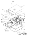
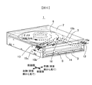
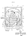
図1に、本発明に係わる光ディスク装置の一実施例の概略構造を、分解斜視図で示す。図2に図1で示した光ディスク装置の外観斜視図を、図3にそのトップカバーを除いた一部省略平面図を、図4に図3におけるA−A断面図を、図5に図3におけるB−B断面図を示す。本実施例および以降の実施例では、主としてタワー型やデスクトップ型パソコンに搭載される形態の光ディスク装置1を取り上げて説明する。
FIG. 1 is an exploded perspective view showing a schematic structure of an embodiment of an optical disk apparatus according to the present invention. 1 is an external perspective view of the optical disk apparatus shown in FIG. 1, FIG. 3 is a partially omitted plan view excluding its top cover, FIG. 4 is a cross-sectional view taken along line AA in FIG. BB sectional drawing in is shown. In this embodiment and the following embodiments, the
光ディスク装置1は、筐体の上・側面がトップカバー2で、下面がボトムカバー3で、前面をフロントパネル4で、背面がメカブロック5(前・側面のやや内側にも延びた骨格をなす)で覆われ、筐体内部にはディスク6が載置されるトレイ7がやや上部に、信号処理および電源供給等を行う配線基板8が最下部に、それらの間に後述の各機構を備えるメカシャシー9が納められている。トレイ7はディスク6の脱着のため前面側に移動可能になっており、左右端面がメカブロック5に支持されるので筐体を上下に区画する構造となる。その内側の開口16には、ディスク6を(一般に上部から見て右回り方向に)回転させるディスク回転機構部10と、ディスク6の情報の記録・再生を(一般にディスク回転機構部付近から背面側に移動しながら)行うレーザ等の光学系をもつピックアップ11とがメカシャシー9に固定される形で配置されている。ディスク回転機構部10とピックアップ11や移動・脱着のため各機構等は、筐体の最下部の配線基板8とフレキシブルプリント配線板(図示せず)により接続されて信号処理・電源供給が行われ、配線基板8からパソコンの内部配線へは筐体の背面下部の接続部品14で接続されている。またパソコン実装状態では、光ディスク装置1の上・下面および左右の側面の前面から奥行き中央までの部分は、パソコン内部への固定部品でほぼ覆われる。ディスク6の記録・再生時には、光ディスク装置1内でピックアップ11の光学系とディスク回転機構部10および配線基板8が発熱し、特に高記録速度や記録枚数が多い条件では、最も発熱密度が大きいピックアップ11でレーザ等の部品が保証温度以上になる可能性が出てくる。従って、光ディスク装置1の内部冷却では、内部全体を低温にする冷却性能の向上と共に、特に高温となるピックアップ11の温度を大幅に下げる効率的な冷却が求められる。
The
この実施例では、外部空気15aの第1の開口12を、筐体の背面側から見て右側の背面で内部のトレイ7下面からピックアップ11下端近傍までの高さの範囲に設け、内部空気15bの第2の開口13を背面側から見て左側の背面で内部のトレイ7上面より上部に設けている。一般に、ディスク6への記録・再生時には、ディスク6がトレイ7よりやや上部で回転し周囲の内部空気15bにも回転流を生じるので、トレイ7より上部の区画ではディスク6の外周側で高圧となると共にディスク6から背面側から見て左側の隅部に向かう内部空気15bの強い流れが形成される。一方、トレイ7より下部の区画では、ディスク6周囲とはトレイ7の中央の開口16で部分的に連通しているものの、開口16がディスク6の内周から外周まで延びており幅も狭いために区画内は上部より低圧となる。また、上記のトレイ7上部の内部空気15bの強い流れの影響により、開口16の周辺に背面側から見て右側で上部に吸い出される流れ(ディスク内周寄り)と左側で上部から左側隅部寄りに漏れ込む循環内部空気15b‘の流れ(ディスク外周寄り)が形成されるものの、全体としては弱い流れしかできない。
In this embodiment, the
第1の開口12と第2の開口13が上記のように設けられていると、まず吸気側では、外部空気15aが第1の開口12からディスク6の回転中心に向かって水平ないし徐々に上向きに流れて大半がピックアップ11に達するというようにあまり分散されることなく円滑に流れ、その部分で開口16から上部に吸い出される流れにより向きを大きく変えてトレイ上部に流入し内部空気15bと合流するというように流れる。このように第1の開口12から開口16への流れは円滑であり、トレイ7の下部は上部と区画されていて背面や側面は低圧であるため、吸気側の通風抵抗が小さくなる。また、導入した低温の外部空気15aを、あまり分散させることなく特に高温となるピックアップ11の近傍に導き吹き付けることができる。一方、排気側では、第2の開口13がトレイの上部のディスク6から左側の隅部に向かう内部空気15bの強い流れが集中する位置にあるため、円滑に第2の開口13から排出空気15cとして流出させることができ、排気側の通風抵抗が小さくなる。従って、第1の開口12と第2の開口13を適切な位置に設けるという簡単な構成で、吸気・排気側の通風抵抗を小さくできるので外気導入量が増やせ、結果として装置内部の全体的な冷却性能を向上できる。また同時に、低温の外部空気15aをあまり分散させることなく特に高温となるピックアップ11に集中できるので、効率的な冷却も達成される。なお、この実施例では、背面の中で第1の開口12を背面側から見て右側、第2の開口13を左側だけに配置したが、各々を中央や逆側に開口の幅を広げたり開口を追加したりしても、少なくとも上記の元々の位置での開口の作用・効果は同様に現れるので、装置内部の冷却に関しては同様な性能向上と効率化が得られる。
When the first opening 12 and the
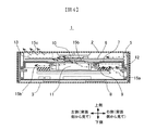
本発明に係わる光ディスク装置の他の実施例を、図6〜図8を用いて説明する。図6は光ディスク装置の外観斜視図であり、図7は図6に示した光ディスク装置のトップカバーを除いた一部省略平面図、図8は図7におけるC−C断面図である。なおこれ以降の他の実施例でも共通に、光ディスク装置の各部品には第1の実施例と同じ番号を付けて示し、動作や構造の説明は第1の実施例と異なるものを主体に行うことにする。 Another embodiment of the optical disk apparatus according to the present invention will be described with reference to FIGS. 6 is an external perspective view of the optical disk device, FIG. 7 is a partially omitted plan view of the optical disk device shown in FIG. 6 excluding the top cover, and FIG. 8 is a cross-sectional view taken along the line CC in FIG. It should be noted that, in common with the other embodiments thereafter, each component of the optical disk apparatus is denoted by the same reference numerals as those in the first embodiment, and the description of the operation and structure will be mainly different from the first embodiment. I will decide.
この実施例では、外部空気15aの第1の開口12が筐体の背面側から見て右側の隅部に近い側面で内部のトレイ7下面からピックアップ11下端近傍までの高さの範囲に設けられ、内部空気15bの第2の開口13が背面側から見て左側の隅部に近い側面で内部のトレイ7上面より上側に設けている。既に説明した第1の実施例とは、第1の開口12と第2の開口13を背面側から見て各々同じ側の隅部に近い背面から側面に変えただけである。従って、装置内部の各部品との位置関係や元々形成される内部空気15b等の流れ状態に、第1の実施例と本質的な違いはなく、外気導入による装置の内部冷却の作用・効果は同様に得られると考えられる。以上から、この実施例でも、簡単な構成で外気導入量を増やして装置内部の冷却性能を向上させると共に、特に高温となる部品を効率よく冷却することができる。
In this embodiment, the
本発明に係わる光ディスク装置のさらに他の実施例を、図9および図10を用いて説明する。図9は光ディスク装置のトップカバーを除いた一部省略平面図であり、図10は図9におけるD−D断面図である。 Still another embodiment of the optical disk apparatus according to the present invention will be described with reference to FIGS. FIG. 9 is a partially omitted plan view of the optical disc apparatus excluding the top cover, and FIG. 10 is a sectional view taken along the line DD in FIG.
この実施例では、第1の開口12と第2の開口13を第1の実施例と同様な位置に設けた上で、第1の開口12の内面の開口部からピックアップ11の近傍までダクト状に延びた吸気整流部材17と、背面側から見て左側のトレイ7の上面とトップカバー2の内面の間にメカブロック5からディスク6の外周に延びた板状の排気整流部材18とが追加されている。吸気整流部材17はピックアップ11の移動範囲に相当する側面が開口部となっているので、第1の開口12から入った外部空気15aをほとんど分散させずに特に高温となるピックアップ11の近傍へと導き吹き付けることができ、排気整流部材18によりトレイ7の上部のディスク6から左側の隅部に向かう内部空気15bの流れを、より円滑に第2の開口13の内面の開口部に導くことができる。第1の開口12と第2の開口13による装置内部の冷却の作用・効果は第1の実施例と同様であり、追加した吸気整流部材17と排気整流部材18によりそれらは強化されることになる。従って、この実施例では、簡単な構成で外気導入量を増やして装置内部の冷却性能をさらに向上させると共に、特に高温となる部品をさらに効率よく冷却することができる。
In this embodiment, the
図11は、本発明に係わる光ディスク装置のさらに他の実施例の、トップカバーを除き筐体の背面側から見て右側後半部分を示した一部省略部分平面図である。 FIG. 11 is a partially omitted partial plan view showing the rear half of the right side when viewed from the rear side of the housing except for the top cover, in still another embodiment of the optical disk apparatus according to the present invention.
この実施例では、第3の実施例と同様な構成で、第1の開口12の筐体内側に延ばしたダクト状の吸気整流部材17のピックアップ11の移動範囲に相当する側面に、ピックアップ11とほぼ対向する範囲に限られた開口部をもち、かつピックアップ11と連動して移動する可動整流部材19を追加している。このように吸気整流部材17に可動整流部材19を組み合わせることにより、第1の開口12から入った低温の外部空気15aをほとんど分散させずに特に高温となるピックアップ11の近傍へと導くと共に、そのほぼ全量をピックアップ11がどの位置に移動していても確実に吹き付けることができるようになる。その結果、第3の実施例に比べ、特に高温となるピックアップ11をより一層効率よく冷却することができる。その他の構成は第3の実施例と同様であることから、この実施例では、簡単な構成で外気導入量を増やして装置内部の冷却性能をさらに向上させると共に、特に高温となる部品をより一層効率よく冷却することができる。
In this embodiment, the
図12は、本発明に係わる光ディスク装置のさらに他の実施例の外観斜視図である。 FIG. 12 is an external perspective view of still another embodiment of the optical disc apparatus according to the present invention.
この実施例では、第1の実施例と同様に筐体の背面の右下に設けられた第1の開口12と左上に設けられた第2の開口13との外面の開口部に、防塵用のフィルター20が付け加えられている。これらにより、第1の開口12のフィルター20では侵入の可能性が大きい装置稼動時の防塵が、第2の開口13のフィルター20では侵入量は少ないが装置停止時でも防塵ができるようになる。フィルター20は不織布のような薄いもので除塵性能と通風抵抗のバランスがよいものが好ましいが、通風抵抗の増加を考慮して開口面積を調整すれば外気導入量を適正に確保できるので、第1の実施例と同様な装置の内部冷却に関する性能向上と効率化とが得られる。従って、この実施例では吸気・排気用の開口にフィルターを設置するという簡単な構成で、冷却性能を保ちながら塵の侵入による悪影響を防止できる。
In this embodiment, as in the first embodiment, the
本発明は、光ディスク装置に利用できる。 The present invention can be used in an optical disc apparatus.
6…ディスク、7…トレイ、10…ディスク回転機構部、11…ピックアップ、12…第1の開口、13…第2の開口、15a・15b・15b‘・15c…外部空気・内部空気・循環内部空気・排出空気、16…開口、17…吸気整流部材、18…排気整流部材、19…可動整流部材、20…フィルター。
6 ... disc, 7 ... tray, 10 ... disc rotating mechanism, 11 ... pickup, 12 ... first opening, 13 ... second opening, 15a, 15b, 15b ', 15c ... external air, internal air, circulation inside Air / exhaust air, 16 ... opening, 17 ... intake rectifying member, 18 ... exhaust rectifying member, 19 ... movable rectifying member, 20 ... filter.
Claims (5)
回りに回転させるディスク回転機構部と、前記トレイの下部に設けられ、前記ディスク回
転機構部の回転軸より前記筐体の背面側で、前記筐体の前後方向に移動するピックアップ
とを有し、
前記トレイは、前記ディスク回転機構部の回転軸近傍と前記ピックアップが移動する範囲に開口をもち前記筐体を上下に区画するほぼ矩形板状であり、
前記筐体は、その背面において、吸気口である第1の開口と排気口である第2の開口とを有し、
前記第1の開口はその背面側から見て右側の背面であって、前記トレイの下面から前記ピックアップの下端近傍までの高さの範囲内に配置され、
前記第2の開口は前記筐体の背面側から見て左側の背面であって、前記トレイの上面より上部に配置され、
前記ディスクの回転による空気の流れで、前記第1の開口を通して前記ピックアップ近傍に外気を導入し、前記第2の開口を通して前記ピックアップ近傍の空気を排出すること
を特徴とする光ディスク装置。 A housing, a tray that can be protruded from the front surface of the housing, and on which a disk is placed on the upper surface; provided in the housing from the vicinity of the upper surface of the tray to the lower portion; A disk rotation mechanism section that rotates, and a pickup that is provided at a lower portion of the tray and moves in the front-rear direction of the casing on the back side of the casing from the rotation axis of the disk rotation mechanism section;
The tray has a substantially rectangular plate shape that has an opening in the vicinity of the rotation axis of the disk rotation mechanism and a range in which the pickup moves, and divides the housing vertically.
The housing has a first opening that is an intake port and a second opening that is an exhaust port on the back surface thereof;
The first opening is a right rear when viewed from the back side thereof, are disposed from the lower surface of the tray in the range of height to the vicinity of the lower end of the pickup,
The second opening is a back of the left side as viewed from the rear side of the housing, are arranged from the top upper surface of the tray,
An optical disc apparatus characterized by introducing air in the vicinity of the pickup through the first opening and discharging the air in the vicinity of the pickup through the second opening by an air flow caused by the rotation of the disk.
Priority Applications (5)
| Application Number | Priority Date | Filing Date | Title |
|---|---|---|---|
| JP2005147499A JP4557797B2 (en) | 2005-05-20 | 2005-05-20 | Optical disk device |
| TW094127742A TWI277068B (en) | 2005-05-20 | 2005-08-15 | Optical disk apparatus |
| US11/236,056 US7690008B2 (en) | 2005-05-20 | 2005-09-26 | Optical disc drive having openings in the housing to allow air therein |
| CNB2005101069791A CN100524503C (en) | 2005-05-20 | 2005-09-27 | Optical disc device |
| KR1020050090883A KR100686665B1 (en) | 2005-05-20 | 2005-09-29 | Optical disk apparatus |
Applications Claiming Priority (1)
| Application Number | Priority Date | Filing Date | Title |
|---|---|---|---|
| JP2005147499A JP4557797B2 (en) | 2005-05-20 | 2005-05-20 | Optical disk device |
Publications (3)
| Publication Number | Publication Date |
|---|---|
| JP2006323955A JP2006323955A (en) | 2006-11-30 |
| JP2006323955A5 JP2006323955A5 (en) | 2008-04-03 |
| JP4557797B2 true JP4557797B2 (en) | 2010-10-06 |
Family
ID=37425384
Family Applications (1)
| Application Number | Title | Priority Date | Filing Date |
|---|---|---|---|
| JP2005147499A Expired - Fee Related JP4557797B2 (en) | 2005-05-20 | 2005-05-20 | Optical disk device |
Country Status (5)
| Country | Link |
|---|---|
| US (1) | US7690008B2 (en) |
| JP (1) | JP4557797B2 (en) |
| KR (1) | KR100686665B1 (en) |
| CN (1) | CN100524503C (en) |
| TW (1) | TWI277068B (en) |
Families Citing this family (9)
| Publication number | Priority date | Publication date | Assignee | Title |
|---|---|---|---|---|
| JP4479662B2 (en) * | 2005-03-10 | 2010-06-09 | パナソニック株式会社 | Optical disk device |
| CA2742267C (en) | 2008-10-31 | 2019-06-04 | Centocor Ortho Biotech Inc. | Differentiation of human embryonic stem cells to the pancreatic endocrine lineage |
| JP4643762B2 (en) * | 2009-01-07 | 2011-03-02 | パナソニック株式会社 | Electronics |
| TW201133193A (en) * | 2010-03-29 | 2011-10-01 | Hon Hai Prec Ind Co Ltd | Computer enclosure |
| MX351515B (en) | 2010-05-12 | 2017-10-17 | Janssen Biotech Inc | Differentiation of human embryonic stem cells. |
| JPWO2013073188A1 (en) * | 2011-11-15 | 2015-04-02 | パナソニックIpマネジメント株式会社 | In-vehicle optical disk device |
| KR102084561B1 (en) | 2012-12-31 | 2020-03-04 | 얀센 바이오테크 인코포레이티드 | Culturing of human embryonic stem cells at the air-liquid interface for differentiation into pancreatic endocrine cells |
| JP2014207034A (en) * | 2013-04-12 | 2014-10-30 | ソニー株式会社 | Disk drive unit |
| CN105356313B (en) * | 2015-11-19 | 2017-10-27 | 国家电网公司 | Electric power cabinet |
Citations (3)
| Publication number | Priority date | Publication date | Assignee | Title |
|---|---|---|---|---|
| JPH06236677A (en) * | 1993-02-12 | 1994-08-23 | Ricoh Co Ltd | Optical information recording and reproducing device |
| JP2001155479A (en) * | 1999-11-25 | 2001-06-08 | Sony Corp | Disk device |
| JP2003151259A (en) * | 2001-11-09 | 2003-05-23 | Hitachi-Lg Data Storage Inc | Optical disk device |
Family Cites Families (11)
| Publication number | Priority date | Publication date | Assignee | Title |
|---|---|---|---|---|
| JPH04195885A (en) * | 1990-11-28 | 1992-07-15 | Hitachi Ltd | Optical disk device |
| JPH04358389A (en) | 1991-06-05 | 1992-12-11 | Mitsubishi Electric Corp | Magnetic disk device |
| US6639886B1 (en) * | 2000-07-14 | 2003-10-28 | Visteon Global Technologies, Inc. | Thermal management system in single or multiplayer disk system |
| KR100655206B1 (en) * | 2002-10-10 | 2006-12-11 | 마쯔시다덴기산교 가부시키가이샤 | Optical disk device |
| JP2004241024A (en) | 2003-02-04 | 2004-08-26 | Shinano Kenshi Co Ltd | Disk drive |
| JP2004259424A (en) * | 2003-02-07 | 2004-09-16 | Shinano Kenshi Co Ltd | Optical disk device |
| JP4311538B2 (en) * | 2003-06-27 | 2009-08-12 | 株式会社日立製作所 | Disk storage device cooling structure |
| JP2005243126A (en) * | 2004-02-25 | 2005-09-08 | Sony Corp | Disk driver |
| WO2005086169A1 (en) * | 2004-03-05 | 2005-09-15 | Matsushita Electric Industrial Co., Ltd. | Optical disk apparatus |
| TWI238996B (en) * | 2004-09-22 | 2005-09-01 | Benq Corp | Optical disk device |
| JP4324570B2 (en) * | 2005-02-15 | 2009-09-02 | 株式会社日立製作所 | Optical disk device |
-
2005
- 2005-05-20 JP JP2005147499A patent/JP4557797B2/en not_active Expired - Fee Related
- 2005-08-15 TW TW094127742A patent/TWI277068B/en not_active IP Right Cessation
- 2005-09-26 US US11/236,056 patent/US7690008B2/en not_active Expired - Fee Related
- 2005-09-27 CN CNB2005101069791A patent/CN100524503C/en not_active Expired - Fee Related
- 2005-09-29 KR KR1020050090883A patent/KR100686665B1/en not_active IP Right Cessation
Patent Citations (3)
| Publication number | Priority date | Publication date | Assignee | Title |
|---|---|---|---|---|
| JPH06236677A (en) * | 1993-02-12 | 1994-08-23 | Ricoh Co Ltd | Optical information recording and reproducing device |
| JP2001155479A (en) * | 1999-11-25 | 2001-06-08 | Sony Corp | Disk device |
| JP2003151259A (en) * | 2001-11-09 | 2003-05-23 | Hitachi-Lg Data Storage Inc | Optical disk device |
Also Published As
| Publication number | Publication date |
|---|---|
| CN100524503C (en) | 2009-08-05 |
| CN1866388A (en) | 2006-11-22 |
| KR20060119676A (en) | 2006-11-24 |
| KR100686665B1 (en) | 2007-02-26 |
| US20060265721A1 (en) | 2006-11-23 |
| US7690008B2 (en) | 2010-03-30 |
| TW200641825A (en) | 2006-12-01 |
| JP2006323955A (en) | 2006-11-30 |
| TWI277068B (en) | 2007-03-21 |
Similar Documents
| Publication | Publication Date | Title |
|---|---|---|
| JP4557797B2 (en) | Optical disk device | |
| JP4686427B2 (en) | Electronics | |
| JP4776472B2 (en) | Storage device | |
| JP4324570B2 (en) | Optical disk device | |
| US7914366B2 (en) | Storage apparatus | |
| US8238054B2 (en) | Hard disk drive having desiccant member | |
| JP2007188599A (en) | Electronic device | |
| JP5882818B2 (en) | Electronics | |
| JP2003151259A (en) | Optical disk device | |
| JP2007012260A (en) | Hard disk drive and storage device | |
| JP2006108324A (en) | Electronic device | |
| TWI264710B (en) | Disc apparatus | |
| JP4516396B2 (en) | Electronic equipment | |
| JP2004127467A (en) | Storage device and electronic device equipped with storage device | |
| JPWO2007077709A1 (en) | Disk unit | |
| JP4685692B2 (en) | Electronics | |
| JP2001155479A (en) | Disk device | |
| JP2599972Y2 (en) | Internal cooling structure of recording device | |
| JP2003249070A (en) | Disk drive unit, electronic apparatus, and cooling disk | |
| US20080155578A1 (en) | Optical Disk Drive Unit Having a Cooling Device | |
| JP2007004894A (en) | Electronic device | |
| JP2018129110A (en) | Optical disk drive, information expansion device, and information recording device | |
| JPH09213063A (en) | Attachable/detachable recording medium driving device | |
| JPH04243081A (en) | Optical disk device | |
| JP2010123636A (en) | Cooling structure of electronic equipment |
Legal Events
| Date | Code | Title | Description |
|---|---|---|---|
| A521 | Request for written amendment filed |
Free format text: JAPANESE INTERMEDIATE CODE: A523 Effective date: 20080214 |
|
| A621 | Written request for application examination |
Free format text: JAPANESE INTERMEDIATE CODE: A621 Effective date: 20080214 |
|
| A977 | Report on retrieval |
Free format text: JAPANESE INTERMEDIATE CODE: A971007 Effective date: 20091217 |
|
| A131 | Notification of reasons for refusal |
Free format text: JAPANESE INTERMEDIATE CODE: A131 Effective date: 20100105 |
|
| A521 | Request for written amendment filed |
Free format text: JAPANESE INTERMEDIATE CODE: A523 Effective date: 20100305 |
|
| TRDD | Decision of grant or rejection written | ||
| A01 | Written decision to grant a patent or to grant a registration (utility model) |
Free format text: JAPANESE INTERMEDIATE CODE: A01 Effective date: 20100713 |
|
| A01 | Written decision to grant a patent or to grant a registration (utility model) |
Free format text: JAPANESE INTERMEDIATE CODE: A01 |
|
| A61 | First payment of annual fees (during grant procedure) |
Free format text: JAPANESE INTERMEDIATE CODE: A61 Effective date: 20100720 |
|
| R150 | Certificate of patent or registration of utility model |
Free format text: JAPANESE INTERMEDIATE CODE: R150 |
|
| FPAY | Renewal fee payment (event date is renewal date of database) |
Free format text: PAYMENT UNTIL: 20130730 Year of fee payment: 3 |
|
| LAPS | Cancellation because of no payment of annual fees |