JP4555360B2 - Receiver that receives emergency breaking news in digital terrestrial television broadcasting - Google Patents
Receiver that receives emergency breaking news in digital terrestrial television broadcasting Download PDFInfo
- Publication number
- JP4555360B2 JP4555360B2 JP2008122559A JP2008122559A JP4555360B2 JP 4555360 B2 JP4555360 B2 JP 4555360B2 JP 2008122559 A JP2008122559 A JP 2008122559A JP 2008122559 A JP2008122559 A JP 2008122559A JP 4555360 B2 JP4555360 B2 JP 4555360B2
- Authority
- JP
- Japan
- Prior art keywords
- receiver
- emergency
- information
- flag
- warning
- Prior art date
- Legal status (The legal status is an assumption and is not a legal conclusion. Google has not performed a legal analysis and makes no representation as to the accuracy of the status listed.)
- Expired - Fee Related
Links
- 238000004364 calculation method Methods 0.000 claims description 101
- 238000001514 detection method Methods 0.000 claims description 66
- 238000012544 monitoring process Methods 0.000 claims description 29
- 238000004458 analytical method Methods 0.000 claims description 20
- 238000012937 correction Methods 0.000 claims description 16
- 230000001360 synchronised effect Effects 0.000 claims description 12
- 125000004122 cyclic group Chemical group 0.000 claims description 9
- 238000000605 extraction Methods 0.000 claims description 9
- 230000004913 activation Effects 0.000 description 97
- 230000005540 biological transmission Effects 0.000 description 89
- 230000010365 information processing Effects 0.000 description 28
- 238000000034 method Methods 0.000 description 25
- 230000033001 locomotion Effects 0.000 description 18
- 239000000969 carrier Substances 0.000 description 15
- 230000006870 function Effects 0.000 description 9
- 238000006243 chemical reaction Methods 0.000 description 7
- 230000003321 amplification Effects 0.000 description 6
- 230000015654 memory Effects 0.000 description 6
- 238000003199 nucleic acid amplification method Methods 0.000 description 6
- 238000012549 training Methods 0.000 description 6
- 238000010586 diagram Methods 0.000 description 4
- 238000005516 engineering process Methods 0.000 description 4
- 238000012545 processing Methods 0.000 description 4
- 230000035945 sensitivity Effects 0.000 description 4
- 230000007246 mechanism Effects 0.000 description 3
- 230000008859 change Effects 0.000 description 2
- 230000000295 complement effect Effects 0.000 description 2
- 239000000284 extract Substances 0.000 description 2
- 230000002265 prevention Effects 0.000 description 2
- 230000015572 biosynthetic process Effects 0.000 description 1
- 230000003139 buffering effect Effects 0.000 description 1
- 230000000694 effects Effects 0.000 description 1
- 230000006872 improvement Effects 0.000 description 1
- 238000009434 installation Methods 0.000 description 1
- 238000012423 maintenance Methods 0.000 description 1
- 230000008569 process Effects 0.000 description 1
- 238000003672 processing method Methods 0.000 description 1
- 239000012925 reference material Substances 0.000 description 1
- 230000002787 reinforcement Effects 0.000 description 1
- 238000006467 substitution reaction Methods 0.000 description 1
- 239000000758 substrate Substances 0.000 description 1
- CCEKAJIANROZEO-UHFFFAOYSA-N sulfluramid Chemical group CCNS(=O)(=O)C(F)(F)C(F)(F)C(F)(F)C(F)(F)C(F)(F)C(F)(F)C(F)(F)C(F)(F)F CCEKAJIANROZEO-UHFFFAOYSA-N 0.000 description 1
- 238000003786 synthesis reaction Methods 0.000 description 1
- 230000001960 triggered effect Effects 0.000 description 1
Images


Description
本発明は、地上デジタルテレビジョン放送において緊急情報を送受信する技術に関し、特に、緊急警報放送または緊急地震速報が発せられた際に、迅速、かつ、確実に受信する受信機、及び、受信機のユーザに確実に伝達するための送信装置に関する。 The present invention relates to a technology for transmitting and receiving emergency information in digital terrestrial television broadcasting, and in particular, a receiver for receiving promptly and surely when an emergency warning broadcast or an earthquake early warning is issued, and the receiver The present invention relates to a transmission device for reliably transmitting to a user.
テレビジョン放送やラジオ放送において、地震や津波などの災害が発生したとき、いち早く視聴者に伝達できるように、緊急警報放送という放送システムがある。このシステムでは、緊急情報を伝える放送が開始される前に、起動されていない端末を起動できるようにする仕組みを設けている。 In television broadcasting and radio broadcasting, there is a broadcasting system called emergency warning broadcasting so that when a disaster such as an earthquake or tsunami occurs, it can be quickly transmitted to viewers. This system is provided with a mechanism that allows a terminal that has not been activated to be activated before the broadcast that conveys emergency information is started.
日本の地上デジタルテレビジョン放送であるISDB−T(Integrated Services Digital Broadcasting−Terrestrial、ARIB規格STD‐B31)方式においては、TMCC(Transmission and Multiplexing Configuration Control: 伝送制御)キャリアは緊急警報放送用起動フラグを有している。 In the ISDB-T (Integrated Services Digital Broadcasting-Terrestrial, ARIB standard STD-B31) system, which is a Japanese terrestrial digital television broadcast, TMCC (Transmission and Multiplexing Configuration Carrier Control: Emergency Control Carrier Transmission Control: Flag for Emergency Control Transmission Control) Have.
ISDB−T方式の地上デジタルテレビジョン受信機は、該受信機の電源が入っていない場合に、TMCCキャリアに格納される緊急警報放送用起動フラグを検出する伝送制御信号受信回路を備えることにより、緊急警報放送用起動フラグが1(「起動制御あり(緊急警報放送あり)」に対応する)のとき、受信機の電源を投入し、受信機のユーザに緊急警報放送の視聴を促すことができる。 The ISDB-T digital terrestrial television receiver includes a transmission control signal receiving circuit that detects an emergency warning broadcast activation flag stored in the TMCC carrier when the receiver is not powered. When the emergency alert broadcast activation flag is 1 (corresponding to “with activation control (with emergency alert broadcast)”), the receiver can be turned on to prompt the user of the receiver to view the emergency alert broadcast. .
これを実現するためには、受信機内の伝送制御信号受信回路が緊急警報放送用起動フラグを常時監視していなければならない。即ち、受信機が消費電力を節約するための待機モードであるにも関らず、緊急警報放送用起動フラグを常時監視することになるため、受信機の待機消費電力が問題になることがよくある。 In order to realize this, the transmission control signal receiving circuit in the receiver must always monitor the emergency warning broadcast activation flag. That is, the standby power consumption of the receiver is often a problem because the emergency warning broadcast activation flag is constantly monitored even though the receiver is in a standby mode for saving power consumption. is there.
この待機消費電力を抑えて動作し、電源が供給されていなかった受信機を起動して、緊急警報放送の有無を受信者に知らせる幾つかの技術が開示されている(例えば、特許文献1,特許文献2参照)。
Several technologies have been disclosed that operate with this standby power consumption suppressed, start a receiver that has not been supplied with power, and inform the receiver of the presence or absence of an emergency warning broadcast (for example,
例えば、特許文献1が開示する受信機において、伝送制御信号受信回路は、TMCC信号のフレーム同期信号に基づく同期保持回路を備え、同期保持回路によるカウント値の示すタイミングで、フレーム内及びフレーム単位(フレーム外)の間欠動作を行うことにより、消費電力を節約することができる。フレーム内の電源投入タイミングは、例えば、同期信号から緊急警報放送用起動フラグまでの約30msecである。
For example, in the receiver disclosed in
また、特許文献2が開示する受信機は、伝送制御信号受信回路の回路構成を簡略化することにより、より低消費電力化を図っている。更に、ダイバシティ合成を得るために、部分受信セグメント内の4本全てのTMCC信号を用いて、緊急警報放送用起動フラグの受信精度を高めるようにしている。
Further, the receiver disclosed in
一方、気象庁は、平成19年10月1日から緊急地震速報(例えば、非特許文献1参照)の一般への提供を開始した。これに伴い、テレビジョン並びにラジオの各放送局も、緊急地震速報が発表される際にはチャイム音とともにテレビジョン画面に表示または音声で伝えるなどの放送を実施することを開始した。尚、緊急地震速報のラジオ放送の一部は、平成20年4月1日から開始している。
On the other hand, the Japan Meteorological Agency started providing earthquake early warnings (see Non-Patent
地上デジタルテレビジョン放送、特に部分受信のワンセグサービスの場合、無線周波数(RF)信号の復調、誤り訂正、映像等のコーデックなどの信号処理に要する遅延のため、テレビジョン画面に表示されるまでに何秒かの遅延が発生する。 In the case of digital terrestrial television broadcasting, especially in the case of partial reception one-segment services, the delay required for signal processing such as radio frequency (RF) signal demodulation, error correction, and codec processing for video, etc. There will be a delay of several seconds.
また、緊急警報放送の場合と同様に、受信機に電源供給する仕組みがなければ、受信もできないのは同様である。 Similarly to the case of emergency alert broadcasting, the reception is not possible without a mechanism for supplying power to the receiver.
そこで、緊急地震速報を含む災害、防災情報等の地上デジタルテレビジョン放送における伝送のため、TMCC信号による起動フラグの受信に加え、ACキャリアを利用する技術が開示されている(例えば、特許文献3参照)。この技術によれば、TMCCキャリアの緊急警報放送用起動フラグと、例えば部分受信セグメント内の特定のACキャリアに置かれた信号種別ビットとの組合せにより、緊急速報の種別及び開始又は終了を提示する。その他ARIB規格STD‐B10の緊急情報記述子及び緊急速報の映像・音声を、ACキャリアを用いて伝送する。緊急情報記述子は、信号種別ビットを含み部分受信セグメントのAC信号に、映像・音声は、他のセグメントのAC信号に格納して伝送される。 Therefore, a technique using an AC carrier is disclosed in addition to receiving a start flag by a TMCC signal for transmission in terrestrial digital television broadcasting such as disaster and disaster prevention information including earthquake early warning (for example, Patent Document 3). reference). According to this technology, the type of emergency early warning and the start or end are presented by a combination of an emergency warning broadcast start flag of a TMCC carrier and a signal type bit placed on a specific AC carrier in a partial reception segment, for example. . In addition, the emergency information descriptor of the ARIB standard STD-B10 and the video / audio of the emergency breaking news are transmitted using the AC carrier. The emergency information descriptor includes a signal type bit and is transmitted as an AC signal of a partially received segment, and video / audio is stored as an AC signal of another segment.
この技術においては、受信機の電源が入っていない場合、或いは他のチャンネルを受信している場合に、電源投入又はチャンネル切り替えを促すように制御し、この制御のために部分受信セグメント内のTMCC信号及びAC信号を受信し、電源投入後、又はチャンネル切り替え後に、その他の災害・防災情報及び映像・音声の再生を行う。 In this technology, when the receiver is not turned on, or when another channel is received, control is performed to prompt power-on or channel switching, and the TMCC in the partial reception segment is used for this control. After receiving the signal and the AC signal, after the power is turned on or after the channel is switched, other disaster / disaster prevention information and video / audio are reproduced.
特許文献1〜3に開示される技術はいずれも、地上デジタルテレビジョン放送の受信機を迅速に立ち上げることを目的とする点で同一の技術である。また、特許文献1〜3に開示される技術はいずれも、TMCC信号またはAC信号の受信信号におけるフレーム同期が確立していることを前提としている。
The techniques disclosed in
特に、特許文献3はTMCC信号とAC信号の両方を受信する。これは、回路構成が複雑になると共に、消費電力的にも改善の余地がある。
In particular,
更に、受信機において地上デジタルテレビジョン放送を受信していない時にも、緊急警報放送又は緊急地震速報の発報に迅速に対応するためには、アンテナを収納又は折りたたんだ受信感度の悪い状況においても受信できるようにすることが求められる。 Furthermore, even when the terrestrial digital television broadcast is not received at the receiver, in order to quickly respond to the emergency warning broadcast or the earthquake early warning, even in a situation where the antenna is housed or folded, the reception sensitivity is poor. It is required to be able to receive.
つまり、受信信号の品質が足りずフレーム単位のタイミング同期が不十分な場合にも緊急警報放送又は緊急地震速報の起動フラグを検知し、受信機を有する受信者(受信機のユーザ)に緊急速報(緊急警報放送又は緊急地震速報)の情報を受信することができるようにする必要がある。尚、受信機によって緊急速報の受信を認識することができれば、受信機のユーザは、アンテナを伸ばして更に良好な受信状態にすることができることは云うまでもない。 In other words, even when the quality of the received signal is insufficient and timing synchronization in units of frames is insufficient, the emergency warning broadcast or the earthquake early warning activation flag is detected, and the emergency early warning is given to the receiver (receiver user) having the receiver. It is necessary to be able to receive information of (emergency warning broadcast or earthquake early warning). Needless to say, if the receiver can recognize the reception of the emergency bulletin, the user of the receiver can extend the antenna to obtain a better reception state.
本発明は、地上デジタルテレビジョン放送の受信者への迅速、且つ、確実な緊急速報の伝達を可能とする、地上デジタルテレビジョン放送における緊急速報を受信する受信機、及び緊急速報を送信する送信装置を提供することにある。 The present invention relates to a receiver for receiving an emergency early warning in digital terrestrial television broadcasting, which enables quick and reliable transmission of an emergency early warning to a receiver of the digital terrestrial television broadcast, and a transmission for transmitting the emergency early warning. To provide an apparatus.
地上デジタルテレビジョン放送の部分受信セグメント内の8本のAC(Auxiliary Channel)キャリアを用いて、緊急速報の情報を伝送するシステムにおいて、送信側では、伝送する前記緊急速報の情報とともに、Nビット(Nは整数)の符号列を少なくとも「緊急警報放送用起動フラグ」及び「緊急地震速報用起動・識別フラグ」の状態の組み合わせに付与して伝送する。この際、平常時、或いは緊急警報放送又は緊急地震速報が発せられた時とを区別するために、Nビットの符号列の一部又は全ての値を予め定めた法則に従い非反転(又は反転)の状態(即ち、同相(又は逆相)の値)で、「緊急警報放送用起動フラグ」及び「緊急地震速報用起動・識別フラグ」のいずれに該当する状態であるかを受信側で識別可能にして送信する。一方、受信側では、部分受信セグメント内の8本のAC信号を受信し、AC信号に格納されるNビットの符号列の状態に対応する相関演算を行い、相関演算の結果である相関係数のピーク値の有無から、フレーム同期タイミングを検出するとともに、Nビットの符号列の状態(即ち、「緊急警報放送用起動フラグ」及び「緊急地震速報用起動・識別フラグ」のいずれかに対応する状態の組み合わせ毎の前記符号列による相関演算の計算値)に基づき、少なくとも「緊急警報放送用起動フラグ」又は「緊急地震速報用起動・識別フラグ」の状態を判定し、緊急警報放送または緊急地震速報が発せられたことを認識した場合には、8本のAC信号に前記Nビットの符号列とともに伝送された緊急速報を読み出し、受信側の端末の表示器に当該緊急速報を文字で表示して、或いは端末のスピーカから音で、又は端末のバイブレータによる振動で、端末のユーザに当該緊急速報の発生及びその内容を知らせるようにする。 In a system that transmits emergency early warning information using eight AC (Auxiliary Channel) carriers in a partial reception segment of digital terrestrial television broadcasting, on the transmission side, N bits ( N is an integer) and is transmitted by assigning at least a combination of the states of “emergency warning broadcast activation flag” and “emergency earthquake early warning activation / identification flag”. At this time, in order to distinguish between normal times or when an emergency warning broadcast or an earthquake early warning is issued, a part or all of the N-bit code string is not inverted (or inverted) according to a predetermined rule. Can be identified on the receiving side in the state (ie, in-phase (or reverse-phase) value) that corresponds to either “emergency warning broadcast activation flag” or “emergency earthquake early warning activation / identification flag” And send. On the other hand, the reception side receives 8 AC signals in the partial reception segment, performs a correlation operation corresponding to the state of the N-bit code string stored in the AC signal, and obtains a correlation coefficient as a result of the correlation operation. The frame synchronization timing is detected from the presence or absence of the peak value of N and corresponds to either the state of the N-bit code string (that is, the “emergency warning broadcast activation flag” or “emergency earthquake early warning activation / identification flag”). Based on the calculation value of the correlation calculation by the code sequence for each state combination), at least the state of the “emergency warning broadcast activation flag” or “emergency earthquake early warning activation / identification flag” is determined, and the emergency alarm broadcasting or emergency earthquake When recognizing that a breaking news has been issued, the emergency breaking news transmitted together with the N-bit code string is read into eight AC signals, and the emergency terminal is read on the display of the receiving terminal. Display the broadcast with a letter, or the sound from the speaker of the terminal, or in vibration by a vibrator of the terminal, to inform the occurrence and content of the emergency bulletin to the user's terminal.
即ち、本発明による受信機は、地上デジタルテレビジョン放送波からAC信号を受信する受信機であって、
同期信号を兼ねたフラグと、緊急警報放送又は緊急地震速報の情報を含む緊急速報とを格納する電文情報が、TMCC信号と同一フレーム長からなるAC信号として、送信装置からACキャリアにて伝送されるように予め規定され、
前記フラグが、緊急警報放送の有無、及び緊急地震速報の有無を識別するために、緊急警報放送のフラグ及び緊急地震速報のフラグを含む複数系統のフラグの符号列パターンとして、Nビット(Nは正の整数)の符号列からなり、
前記複数系統の符号列パターンに対応するパターン列を予め記憶する記憶手段と、
地上デジタルテレビジョン放送波を受信してAC信号を抽出するAC抽出手段と、
抽出したAC信号に対して、前記記憶手段から読み出されるパターン列に基づいてスライディング相関演算を実行し、各系統の符号列パターンに対応する相関演算の結果である相関係数を生成する相関演算手段と、
前記各系統の符号列パターンに対応する相関係数のピーク値から、各フラグの状態を表す信号及びフレーム同期用信号に分離するフラグ検出手段と、
前記分離された各フラグの状態から、緊急警報放送の有無、及び緊急地震速報の有無を識別するフラグ監視手段と、
前記分離されたフレーム同期用信号からフレーム同期タイミングを検出するフレーム同期検出手段と、
前記フラグ監視手段によって緊急警報放送が有る旨、又は緊急地震速報が有る旨が識別された場合に、前記フレーム同期検出手段によって検出したフレーム同期タイミングに同期して、前記緊急警報放送の内容又は前記緊急地震速報の内容を解析するAC情報解析手段とを備え、
前記相関演算手段は、受信するAC信号における奇数フレームと偶数フレームとを個別に識別して相関係数のピーク値を検出し、当該フラグの状態を判別することを特徴とする。
That is, a receiver according to the present invention is a receiver that receives an AC signal from a terrestrial digital television broadcast wave,
Telegram information for storing a flag that also serves as a synchronization signal and emergency warning information including emergency warning broadcast or emergency earthquake warning information is transmitted as an AC signal having the same frame length as the TMCC signal from the transmission device by an AC carrier. Pre-defined so that
In order to identify the presence or absence of emergency alert broadcasting and the presence or absence of earthquake early warning, the flag has N bits (N is a symbol string pattern of a plurality of flags including an emergency alert broadcasting flag and an emergency earthquake early warning flag. A positive integer)
Storage means for storing in advance a pattern sequence corresponding to the plurality of code sequence patterns;
AC extraction means for receiving a terrestrial digital television broadcast wave and extracting an AC signal;
Correlation calculation means for executing a sliding correlation calculation on the extracted AC signal based on the pattern string read from the storage means, and generating a correlation coefficient as a result of the correlation calculation corresponding to the code string pattern of each system When,
Flag detection means for separating the peak value of the correlation coefficient corresponding to the code string pattern of each system into a signal indicating the state of each flag and a signal for frame synchronization;
Flag monitoring means for identifying the presence / absence of an emergency warning broadcast and the presence / absence of an emergency earthquake warning from the state of each of the separated flags,
Frame synchronization detection means for detecting frame synchronization timing from the separated frame synchronization signal;
When it is identified by the flag monitoring means that there is an emergency warning broadcast, or there is an emergency earthquake warning, the contents of the emergency warning broadcast or the contents in synchronization with the frame synchronization timing detected by the frame synchronization detection means AC information analysis means for analyzing the contents of the earthquake early warning ,
The correlation calculation means is characterized in that the odd-numbered frame and the even-numbered frame in the received AC signal are individually identified to detect the peak value of the correlation coefficient and determine the state of the flag .
また、本発明による受信機において、前記相関演算手段は、受信するAC信号における奇数フレームと偶数フレームとを個別に識別して相関係数のピーク値を検出し、当該フラグの状態を判別することを特徴とする。 Further, in the receiver according to the present invention, the correlation calculating means separately identifies odd frames and even frames in the received AC signal, detects a peak value of the correlation coefficient, and determines the state of the flag. It is characterized by.
また、本発明による受信機において、ISDB−T方式の地上デジタルテレビジョン放送波の部分受信セグメントにおけるモード3の同期変調モードで、同一内容の緊急速報が8本のAC信号にて伝送されるように予め規定されており、前記相関演算手段は、ダイバシティ利得を得るために該8本のAC信号に対して相関演算を行い、前記フラグの状態を判別することを特徴とする。
Further, in the receiver according to the present invention, in the synchronous modulation mode of
また、本発明による受信機において、前記相関演算手段によって判別したフラグの状態が、緊急地震速報又は緊急警報放送が有ることを示す場合にのみ、対応する緊急警報放送或いは緊急地震速報を復号する復号手段を更に備えることを特徴とする。 Further, in the receiver according to the present invention, only when the state of the flag determined by the correlation calculating means indicates that there is an emergency earthquake warning or emergency warning broadcast, decoding corresponding to the emergency warning broadcast or emergency earthquake warning is decoded. The apparatus further comprises means.
また、本発明による受信機において、前記復号手段によって復号した情報から、当該受信機の位置する地域の震度及び到達予測時間の予測情報を計算する予測情報計算手段を更に備えることを特徴とする。 The receiver according to the present invention further comprises prediction information calculation means for calculating prediction information of seismic intensity and arrival prediction time of the area where the receiver is located from information decoded by the decoding means.
また、本発明による受信機において、前記相関演算手段によって判別したフラグの状態が、緊急地震速報又は緊急警報放送が有ることを示す場合にのみ、当該対応する緊急警報放送或いは緊急地震速報を復号するのに十分な期間で電源供給するように、当該受信機の電源供給の切り替えを行う制御手段を更に備えることを特徴とする。 In the receiver according to the present invention, the corresponding emergency alert broadcast or emergency earthquake bulletin is decoded only when the state of the flag determined by the correlation calculating means indicates that there is an emergency earthquake bulletin or emergency alert broadcast. It is further characterized by further comprising control means for switching the power supply of the receiver so that the power is supplied in a sufficient period.
また、本発明による受信機において、前記制御手段は、前記フラグが緊急地震速報又は緊急警報放送が有る旨を表すフラグ値を取得しない場合に、フレーム内間欠受信動作又はフレーム間間欠受信動作で、前記復号手段に電源供給することを特徴とする。 Further, in the receiver according to the present invention, when the flag does not acquire a flag value indicating that there is an emergency earthquake warning or an emergency warning broadcast, in the intra-frame intermittent reception operation or the inter-frame intermittent reception operation, Power is supplied to the decoding means.
また、本発明による受信機において、前記復号手段は、複数のフレーム間で多数決判定して、前記緊急地震速報を復号することを特徴とする。 In the receiver according to the present invention, the decoding means decodes the emergency earthquake bulletin by making a majority decision between a plurality of frames.
また、本発明による受信機において、前記電文情報は、ISDB−T方式の地上デジタルテレビジョン放送波の部分受信セグメントにおけるモード3の同期変調モードで、同一内容の緊急速報が8本のAC信号にて伝送されるように予め規定されており、前記復号手段は、ダイバシティ利得を得るために該8本のAC信号から当該緊急地震速報を復号することを特徴とする。
In the receiver according to the present invention, the telegram information is in the synchronous modulation mode of
また、本発明による受信機において、前記電文情報は、予め定めた差集合巡回符号方式のパリティビットを含み、前記復号手段は、該差集合巡回符号方式に基づく誤り訂正を行って、当該緊急速報を復号することを特徴とする。 In the receiver according to the present invention, the message information includes a parity bit of a predetermined difference set cyclic code system, and the decoding means performs error correction based on the difference set cyclic code system, and It is characterized by decoding.
また、本発明による受信機において、前記警告発生手段は、当該受信機が備える表示器に文字で表示するか、当該受信機が備えるスピーカから音で発生させるか、当該受信機が備えるバイブレータによる振動警告を発するか、又は通常動作時とは異なる動作で知覚的に警告を発生することを特徴とする。 In the receiver according to the present invention, the warning generating means may display characters on a display provided in the receiver, generate a sound from a speaker provided in the receiver, or vibrate by a vibrator provided in the receiver. It is characterized in that a warning is issued or a warning is generated perceptually in an operation different from that in a normal operation.
また、本発明による受信機において、前記予測情報計算手段は、当該受信機の位置する地域の震度及び到達予測時間の予測情報を計算する代わりに、前記電文情報のうち地震の発生についての情報か、又は該情報と発生時刻又は最大予測震度、又は該地震による強い揺れの虞がある地域の情報とを抽出して警告発生手段に送出する予測情報抽出手段として構成されていることを特徴とする。 Further, in the receiver according to the present invention, the prediction information calculation means is information on occurrence of an earthquake in the telegram information, instead of calculating the prediction information of the seismic intensity and the predicted arrival time of the area where the receiver is located. Alternatively, the information and the occurrence time or the maximum predicted seismic intensity, or the information of the area where there is a risk of strong shaking due to the earthquake, is configured as a prediction information extraction unit configured to send to the warning generation unit .
また、本発明による受信機において、前記復号した緊急地震速報は、複数の地域を識別する地域コード、各地域における予測震度情報、及び各地域における予測到達時間情報を含み、前記予測情報計算手段が、当該受信機の地域的な位置を表す位置情報を検出する位置検出手段と、当該受信機の現在時刻を表す現在時刻情報を検出する現在時刻検出手段とを備え、前記地域コード、前記予測震度情報及び前記予測到達時間情報と、前記位置情報及び前記現在時刻情報とから、当該受信機の位置する地域の震度及び到達予測時間の予測情報を計算することを特徴とする。 In the receiver according to the present invention, the decoded earthquake early warning includes a region code for identifying a plurality of regions, predicted seismic intensity information in each region, and predicted arrival time information in each region, and the predicted information calculation means includes A position detection means for detecting position information representing the regional position of the receiver; and a current time detection means for detecting current time information representing the current time of the receiver, the area code, the predicted seismic intensity From the information, the predicted arrival time information, and the position information and the current time information, the seismic intensity of the area where the receiver is located and the predicted information of the predicted arrival time are calculated.
また、本発明による受信機において、前記復号した緊急地震速報は、地震の発生時刻、震源の緯度及び経度、震源の深さ、及びマグニチュードに関する情報を含み、前記予測情報計算手段が、当該受信機の地域的な位置を表す位置情報を検出する位置検出手段と、当該受信機の現在時刻を表す現在時刻情報を検出する現在時刻検出手段とを備え、前記地震の発生時刻、前記震源の緯度及び経度、前記震源の深さ、及び前記マグニチュードに関する情報と、前記位置情報及び前記現在時刻情報とから、当該受信機の位置する地域の震度及び到達予測時間の予測情報を計算することを特徴とする。 In the receiver according to the present invention, the decoded emergency earthquake bulletin includes information on the occurrence time of the earthquake, the latitude and longitude of the epicenter, the depth of the epicenter, and the magnitude, and the prediction information calculation means includes the receiver. Position detecting means for detecting position information representing the regional position of the receiver, and current time detecting means for detecting current time information representing the current time of the receiver, the occurrence time of the earthquake, the latitude of the epicenter and From the information on the longitude, the depth of the epicenter, and the magnitude, and the position information and the current time information, the seismic intensity and the predicted arrival time of the area where the receiver is located are calculated. .
また、本発明による受信機において、前記復号した緊急地震速報は、現在時刻、地震が発生してから現在時刻までの経過時間、震源の緯度及び経度、震源の深さ、及びマグニチュードの情報を含み、前記予測情報計算手段が、当該受信機の地域的な位置を表す位置情報を検出する位置検出手段を備え、前記現在時刻、前記経過時間、前記震源の緯度及び経度、前記震源の深さ、及び前記マグニチュードの情報と、前記位置情報とから、当該受信機の位置する地域の震度及び到達予測時間の予測情報を計算することを特徴とする。 In the receiver according to the present invention, the decoded earthquake early warning includes information on the current time, the elapsed time from the occurrence of the earthquake to the current time, the latitude and longitude of the epicenter, the depth of the epicenter, and the magnitude information. The prediction information calculation means includes position detection means for detecting position information indicating a local position of the receiver, the current time, the elapsed time, the latitude and longitude of the epicenter, the depth of the epicenter, And, based on the magnitude information and the position information, prediction information of the seismic intensity and the predicted arrival time of the area where the receiver is located is calculated.
本発明によれば、地上デジタルテレビジョン放送の受信機への迅速、且つ、確実な緊急警報放送または緊急地震速報の伝達が可能となる。 According to the present invention, it is possible to quickly and surely transmit an emergency warning broadcast or an earthquake early warning to a terrestrial digital television broadcast receiver.
まず、本発明による一実施例の送信装置及び受信機について説明する。 First, a transmission apparatus and a receiver according to an embodiment of the present invention will be described.
(実施例1)
本発明による実施例1の送信装置は、後述する実施例1の電文情報のフォーマットに基づく緊急速報(以下、緊急警報放送及び緊急地震速報を含む情報を総括して、緊急速報と称する)を、ISDB−T方式の地上デジタルテレビジョン放送のOFDM(Orthogonal Frequency Division Multiplexing)方式に多重される各副搬送波のうちACキャリアを用いて伝送する。ISDB−T方式の地上デジタルテレビジョン放送に係る送信装置のハードウェア構成は既知であり、図示しない。
Example 1
The transmission apparatus according to the first embodiment of the present invention is an emergency bulletin based on the format of the telegram information according to the first embodiment described later (hereinafter, the information including the emergency warning broadcast and the earthquake early warning is collectively referred to as emergency bulletin). Transmission is performed using an AC carrier among subcarriers multiplexed in the OFDM (Orthogonal Frequency Division Multiplexing) scheme of terrestrial digital television broadcasting of the ISDB-T scheme. The hardware configuration of the transmission apparatus related to ISDB-T digital terrestrial television broadcasting is known and not shown.
即ち、TMCC信号と同一フレーム長であり(好適には、TMCC信号と同一の位相基準にする)、同期信号を兼ねた、緊急地震速報の有無を識別するビットを含むフラグと、緊急地震速報の情報を含む緊急速報とを格納する電文情報(後述する電文情報のフォーマット)が、送信装置からACキャリアにて伝送されるように予め規定されている。尚、本発明の理解を容易とするために、ISDB−T方式の地上デジタルテレビジョン放送におけるモード3のACキャリアが運ぶAC情報の全てを用いる場合について説明するが、他のモードにおいても適用可能であることに留意する。
That is, the flag has the same frame length as that of the TMCC signal (preferably, the same phase reference as that of the TMCC signal), the flag including the bit for identifying the presence / absence of the earthquake early warning that also serves as the synchronization signal, The telegram information (the format of telegram information to be described later) for storing the emergency bulletin including the information is defined in advance so as to be transmitted from the transmission device on the AC carrier. In order to facilitate understanding of the present invention, the case where all AC information carried by the
例えば、放送事業者は、例えば気象庁から緊急地震速報を受信した場合、送信装置によって、実施例1の電文情報のフォーマット例に基づく同じ緊急地震速報情報、即ち震度や到達予測時間の情報を、少なくとも「緊急警報放送用起動フラグ」及び「緊急地震速報用起動・識別フラグ」の状態の組み合わせに付与したNビット(Nは整数)の符号列とともに、8箇所のACキャリアが運ぶAC情報の全てに格納し、受信機1に向けて送信する。尚、平常時、或いは緊急警報放送又は緊急地震速報が発せられた時には、Nビットの符号列の一部又は全ての値を予め定めた法則に従い非反転(又は反転)の状態(即ち、同相(又は逆相)の値)とし、「緊急警報放送用起動フラグ」及び「緊急地震速報用起動・識別フラグ」の該当する状態を区別して送信する。
For example, when a broadcaster receives, for example, an earthquake early warning from the Japan Meteorological Agency, at least the same earthquake early warning information based on the format example of the telegram information of the first embodiment, that is, information on seismic intensity and arrival prediction time is transmitted by the transmitting device. Along with the N-bit (N is an integer) code string assigned to the combination of the status of the “emergency warning broadcast activation flag” and “emergency earthquake early warning activation / identification flag”, all the AC information carried by the eight AC carriers Store and transmit to the
一方、受信機1(詳細に後述する)は、部分受信セグメント内の8本のAC信号を受信し、AC信号に格納されるNビットの符号列の状態に該当する相関演算を行い、相関演算の結果である相関係数のピーク値の有無から、フレーム同期タイミングを検出するとともに、Nビットの符号列の状態(「緊急警報放送用起動フラグ」及び「緊急地震速報用起動・識別フラグ」の該当する状態の組み合わせ毎の前記符号列による相関演算の計算値)に基づき、少なくとも「緊急警報放送用起動フラグ」又は「緊急地震速報用起動・識別フラグ」の状態を判定し、緊急警報放送又は緊急地震速報が発せられたことを認識した場合には、8本のAC信号にNビットの符号列とともに伝送された緊急速報を読み出し、警告を発生する。警告の発生方法として、受信機1を具備する端末の表示器に当該緊急速報を文字で表示するか、又は該端末のスピーカに音を発生させるか、或いは該端末のバイブレータによる振動により、端末の利用者に当該緊急速報の発生及びその内容を知らせる。
On the other hand, the receiver 1 (described in detail later) receives eight AC signals in the partial reception segment, performs a correlation operation corresponding to the state of the N-bit code string stored in the AC signal, and performs a correlation operation. The frame synchronization timing is detected from the presence / absence of the peak value of the correlation coefficient, which is the result of the Based on the calculation value of the correlation calculation by the code string for each combination of the corresponding states), at least the state of the “emergency warning broadcast activation flag” or “emergency earthquake early warning activation / identification flag” is determined, When recognizing that the earthquake early warning has been issued, the emergency early warning transmitted along with the N-bit code string to the eight AC signals is read and a warning is generated. As a method for generating a warning, the emergency warning is displayed in characters on the display of the terminal equipped with the
ISDB−T方式の地上デジタルテレビジョン放送では、TMCC信号の緊急警報放送用起動フラグを検出することにより、緊急警報放送の有無を知ることができる。一方、緊急地震速報やその他の緊急速報の場合には、その情報の伝送と合わせ、現在運用されている仕組みはないため、任意の端末(携帯電話機、PC、置時計など任意の電子機器を含む)は、本発明に係る受信機1を具備させる必要がある。従って、本発明に係る受信機1は、携帯電話、携帯情報端末(PDA)、腕時計、置時計、パーソナルコンピュータ又は家電製品など、あらゆる機器に具備させることができるものである。
In the ISDB-T digital terrestrial television broadcasting, it is possible to know the presence or absence of emergency warning broadcasting by detecting the emergency warning broadcasting activation flag of the TMCC signal. On the other hand, in the case of earthquake early warnings and other emergency early warnings, there is no mechanism currently in operation along with the transmission of that information, so any terminal (including any electronic device such as a mobile phone, PC, table clock) Needs to be equipped with a
ここで、受信機1によって緊急警報放送又は緊急地震速報など緊急速報を受信するためには、受信機1は、緊急速報が開始されることを緊急速報の受信の直前又はその開始時に知る必要があり、そのため後述する相関演算を行う。
Here, in order for the
更に、ワンセグサービスの受信端末などの場合、受信端末の電源が切られており、且つワンセグ信号受信のためのアンテナも収納されていることがあることも容易に予想することができる。このようなアンテナ収納時等にはアンテナ利得が十分に得られず、フレームタイミングの同期が十分に行われない場合がある。このような場合でも、受信機1は、緊急警報放送等の起動フラグを検出する必要があり、この場合においても、本発明に係る後述の相関演算によって、フレーム同期の有無に拘わらず緊急警報放送又は緊急地震速報などの起動フラグの状態を確認でき、同時にフレーム同期も検出して、緊急警報放送又は緊急地震速報を受信することができるようにする。
Furthermore, in the case of a receiving terminal of the one-segment service, it can be easily predicted that the receiving terminal is turned off and an antenna for receiving the one-seg signal may be housed. When the antenna is housed, the antenna gain may not be sufficiently obtained, and the frame timing may not be sufficiently synchronized. Even in such a case, it is necessary for the
このように本発明に係る受信機1を具備する端末が、緊急地震速報など緊急警報放送以外の緊急速報にも対応し、受信機1の電源を切っており、且つアンテナを収容していて十分な受信品質で放送波を受信できずフレームタイミングの同期を確立していない場合にも、緊急警報放送又は緊急地震速報などの起動フラグを迅速、且つ、確実に送受信できるようにする受信機1を提供する。
As described above, the terminal equipped with the
まず、本発明による一実施例の送信装置及び受信機1についての理解を高めるために、図1を参照して説明する。図1は、本発明が開示する緊急速報を受信するための起動フラグの送受信方法を、緊急警報放送用起動フラグのみを送受信する事例で原理的に示したものである。
First, in order to improve the understanding of the transmission apparatus and the
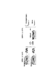
送信側では、緊急警報放送用起動フラグを「1」(緊急警報放送あり)にする代わりに8ビットの符号を割り当てている。当該事例では「11101001」を「1」の代わりに送信している。平常時の場合、即ち緊急警報放送がない場合には、緊急警報放送用起動フラグは「0」(緊急警報放送なし)であり、この場合、先の8ビットの符号のビットを反転し、さらに4ビット回転シフトさせた「01100001」を送信する。 On the transmission side, instead of setting the emergency warning broadcast activation flag to “1” (with emergency warning broadcast), an 8-bit code is assigned. In this case, “111101001” is transmitted instead of “1”. In normal times, that is, when there is no emergency warning broadcast, the emergency warning broadcast activation flag is “0” (no emergency warning broadcast). In this case, the sign bit of the previous 8 bits is inverted, “01100001” that is 4-bit rotationally shifted is transmitted.
受信側では、緊急警報放送用起動フラグを「1」とする「11101001」を持って送信された信号を待つ。該信号を受信した場合、受信した信号の8シンボル分を蓄積し、符号「11101001」との間で相関係数を計算する。尚、図1にあるように相関演算はBPSK波の各変調信号値、つまり、「1,1,1,−1,1,−1,−1,1」と「1,1,1,−1,1,−1,−1,1」、又は「1,1,1,−1,1,−1,−1,1」と「−1,1,1,−1,−1,−1,−1,1」(或いは、「−1,−1,−1,1,−1,1,1,−1」と「−1,−1,−1,1,−1,1,1,−1」、又は「−1,−1,−1,1,−1,1,1,−1」と「1,−1,−1,1,1,1,1,−1」)との間で行う。 The receiving side waits for a signal transmitted with “11101001” which sets the emergency alert broadcast activation flag to “1”. When the signal is received, 8 symbols of the received signal are accumulated, and a correlation coefficient is calculated with the code “11110001”. As shown in FIG. 1, the correlation calculation is performed for each modulation signal value of the BPSK wave, that is, “1,1,1, −1,1, −1, −1,1” and “1,1,1, − 1,1, -1, -1, -1, "or" 1,1,1, -1,1, -1, -1, -1, "and" -1,1,1, -1, -1, -1, " 1, -1,1, "(or" -1, -1, -1, -1, -1, -1,1,1, -1 "and" -1, -1, -1, -1, -1, -1,1, "). 1, -1 "or" -1, -1, -1, 1, -1, 1, 1, -1 "and" 1, -1, -1, 1, 1, 1, 1, -1 " ).
その結果、符号「00010110」が送信されている平常時は、受信機1での相関係数は無相関であるため、0付近の雑音のような値が続く。
As a result, during normal times when the code “00010110” is transmitted, the correlation coefficient at the
一方、符号「11101001」が送信される、放送局の送信装置から緊急警報放送が送信される際には、受信機1では自己相関係数と同等な高い数値が検出され、これにより緊急警報放送が送信されていることを認識することができる。
On the other hand, when an emergency warning broadcast is transmitted from a broadcasting station transmitting apparatus in which a code “111101001” is transmitted, the
図1ではBPSK波としたが、TMCC信号と同一の変調フォーマットとする場合にはDBPSK波となる。DBPSK波を用いた場合でも、つまり、「1,1,1,−1,1,−1,−1,1」、又は「−1,−1,−1,1,−1,1,1,−1」の代わりに「−1,1,−1,−1,1,1,1,−1」(開始の位相が「1」の時)、又は「1,−1,1,1,−1,−1,−1,1」(開始の位相が「1」の時)を用いて相関演算を行っても結果は同様に得られる。 Although the BPSK wave is shown in FIG. 1, the DBPSK wave is used when the modulation format is the same as that of the TMCC signal. Even when DBPSK waves are used, that is, "1, 1, 1, -1, 1, -1, -1, 1" or "-1, -1, -1, 1, -1, 1, 1". , -1 "instead of" -1, 1, -1, -1, 1, 1, 1, -1 "(when the start phase is" 1 "), or" 1, -1, 1, 1 , −1, −1, −1, 1 ”(when the start phase is“ 1 ”), the result is obtained in the same manner.
実施例1は、特に、緊急地震速報の配信において所望される、“どの地域において、どれぐらいの規模/震度の地震がいつ起こるか”に関する緊急速報を送受信する事例について、まず送信側が送信する緊急情報を含む電文情報フォーマットについて説明する。 In the first embodiment, particularly in the case of transmitting and receiving an emergency bulletin regarding “how much earthquake / seismic intensity occurs in which region”, which is desired in the distribution of the emergency earthquake bulletin, first, an emergency transmitted by the transmission side is first transmitted. A message information format including information will be described.
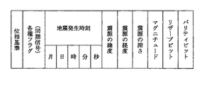
現在の一般向けの緊急地震速報は、日本全国のどこかで強い揺れ(震度5弱以上)が推定される場合に、震度4以上の揺れが推定される地域に関する情報を発信する。 The current public emergency earthquake bulletin provides information on areas where seismic intensity of 4 or higher is estimated when strong shaking (seismic intensity of 5 or lower) is estimated anywhere in Japan.
つまり、当該地域名、当該地域における最大予測震度、当該地域への地震の主要動の到達予測時刻に関する緊急速報が対象となる。図2に示す実施例1の電文情報フォーマットは、これらの緊急速報を格納する電文情報が構成されている。 In other words, the subject is an emergency bulletin regarding the region name, the maximum predicted seismic intensity in the region, and the predicted arrival time of the main motion of the earthquake in the region. The message information format of the first embodiment shown in FIG. 2 includes message information for storing these emergency bulletins.
例えば放送事業者は、気象庁から緊急地震速報を受信した場合、送信装置によって、実施例1の電文情報のフォーマット例に基づく同じ緊急地震速報の情報、即ち当該地域名、当該地域における最大予測震度や地震の主要動の到達予測時刻といった緊急地震速報の情報を、8箇所のACキャリアが運ぶAC情報の全てに格納して、受信機1に向けて送信する。
For example, when a broadcaster receives an emergency earthquake bulletin from the Japan Meteorological Agency, the information on the same earthquake early warning based on the format example of the telegram information of the first embodiment, that is, the area name, the maximum predicted seismic intensity in the area, The information of the emergency earthquake bulletin such as the predicted arrival time of the main motion of the earthquake is stored in all the AC information carried by the eight AC carriers and transmitted to the
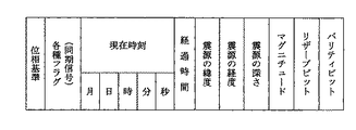
「各種フラグ(同期信号)」は、本実施例の緊急速報を受信するための起動フラグの送受信方法の主たる部分を表す。「緊急警報放送用起動フラグ」、「緊急地震速報用起動・識別フラグ」、「その他のフラグ」、「通常」/「訓練」の識別、緊急速報の「キャンセル」などの情報を提示する。 “Various flags (synchronization signal)” represents the main part of the transmission / reception method of the activation flag for receiving the emergency early warning of this embodiment. Information such as “emergency warning broadcast activation flag”, “emergency earthquake early warning activation / identification flag”, “other flags”, “normal” / “training” identification, emergency early warning “cancel”, and the like are presented.
このうち、「緊急警報放送用起動フラグ」、「緊急地震速報用起動・識別フラグ」、「その他のフラグ」の緊急速報のフラグは、受信側で相関演算を行うことによりフレームタイミング同期(フレーム同期)の確立の有無に関わらず当該フラグ値の判定が可能なように、Nビット(Nビットはフラグを示す符号列の全長を表し、Nは整数である。)の符号列を割り当ててある。 Of these, the emergency warning broadcast activation flag, emergency earthquake warning activation / identification flag, and other flags for emergency early warning are synchronized with each other by performing correlation calculation on the receiving side. ) Is assigned a code string of N bits (N bit represents the total length of the code string indicating the flag, and N is an integer) so that the flag value can be determined regardless of whether or not it is established.
これは、仮にNの値を16付近の値に設定した場合、TMCC信号の同期信号の検出と同等の感度になることに基づいており、受信側で、TMCC信号の同期信号を用いたフレーム同期の閾値付近であって、且つフレーム同期の未確立な状態の受信信号においても当該Nビットの符号列との相関演算の結果(相関係数)に基づくピーク値の検出を行うことにより、フラグ値を検出することができる。従って、本実施例の受信機1における起動フラグの検出は、フレーム同期の確立によらない。
This is based on the fact that if the value of N is set to a value in the vicinity of 16, the sensitivity is equivalent to the detection of the synchronization signal of the TMCC signal, and the frame synchronization using the synchronization signal of the TMCC signal is performed on the receiving side. By detecting the peak value based on the result of the correlation calculation (correlation coefficient) with the N-bit code string even in the reception signal that is in the vicinity of the threshold value and in an unestablished frame synchronization state, the flag value Can be detected. Therefore, the detection of the activation flag in the
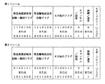
図3に、「各種フラグ(同期信号)」のフォーマット例を示す。ここでは、26ビット(Nに相当する部分のみでは21ビット)を割り当てている。「緊急地震速報用起動・識別フラグ」、「緊急警報放送用起動フラグ」、及び「その他のフラグ」には、各7ビットが割り当てられ、フラグ値の「1」及び「0」の各々に対応するビットとして「1110100」及び「0001011」を入力する(第1フレームの場合)。尚、第2フレームは、「0100111」及び「1011000」を入力する。「通常」/「訓練」の識別、緊急速報の「キャンセル」には各1ビットを割り当て、各々「1」が送信される場合に「訓練」であり、また、「キャンセル」である旨が伝えられる。「リザーブビット(フラグ)」としては、3ビットが用意され、このうちの最後のビットをバッファビットとして、起動フラグの監視時の消費電力を低減するための受信機1における一部の回路への電源供給の間欠動作を行った場合における、起動フラグを検出してから必要な回路に電源供給して、データを検出できるようにするまでの間の緩衝用の時間を確保することができるようになる。残る2ビットには「その他のフラグ」との組み合わせで「津波警報」又は「火山の噴火警報」を入れることもできる。
FIG. 3 shows a format example of “various flags (synchronization signal)”. Here, 26 bits (21 bits only for the portion corresponding to N) are allocated. “Emergency earthquake warning start / identification flag”, “emergency warning broadcast start flag”, and “other flags” are each assigned 7 bits, corresponding to flag values “1” and “0”, respectively. “1110100” and “0001011” are input as the bits to be performed (in the case of the first frame). In the second frame, “0100111” and “1011000” are input. One bit is assigned to each of “normal” / “training” identification and “cancellation” of the emergency bulletin, and when “1” is transmitted, it is “training” and “cancel” is notified. It is done. As the “reserved bit (flag)”, 3 bits are prepared, and the last bit among them is used as a buffer bit, and a part of the circuit in the
ただし、第1フレームと第2フレーム(繰り返し伝送することを想定し、仮に各フレームに番号を振り、その番号から奇数フレームと偶数フレームとしても同じである。)との間では、符号の組み合わせを違えて用いている。これは、図2に記載の電文情報フォーマット例では、最大8つの地域の最大予測震度を計算した結果を伝送するのに、2つのフレームを用いて伝送することに対応する。いずれが第1フレームで、いずれが第2フレームかの認識は、これらの符号の違いを認識することにより行う。 However, between the first frame and the second frame (assuming repeated transmission, a number is assigned to each frame and the same is applied to an odd frame and an even frame from that number). It is used differently. This corresponds to the transmission using two frames to transmit the result of calculating the maximum predicted seismic intensity in a maximum of eight areas in the example of the message information format described in FIG. Which is the first frame and which is the second frame is recognized by recognizing the difference between these codes.
「緊急地震速報用起動・識別フラグ」及び「緊急警報放送用起動フラグ」が「1」で、緊急地震速報及び緊急警報放送が行われる(「その他のフラグ」は「0」)場合、これを受信側において知るために、後述する受信機1は、例えば、第1フレームにおいては、符号長21ビットの「111010011101000001011」を用いて受信信号との間で相関演算を行う。一方、第2フレームにおいては、符号長21ビットの「010011101001111011000」を用いて相関演算を行う。尚、1フレーム分の時間差の2箇所になるが、第1フレームの符号と第2フレームの符号をともに用いて受信AC信号に対し相関演算を行い、相関演算に寄与する符号長を長くすることにより、相関演算の結果における変化の感度を2倍にすることができる。
If the “Emergency Earthquake Warning Start / Identification Flag” and the “Emergency Warning Broadcast Start Flag” are “1” and the Earthquake Early Warning and Emergency Warning Broadcast are performed (“Other Flag” is “0”) In order to know on the receiving side, the
そして、受信機1は、相関演算の結果、相関係数の値がピーク値を検出すると、「緊急地震速報用起動・識別フラグ」及び「緊急警報放送用起動フラグ」が「1」で、「その他のフラグ」は「0」であることが1フレーム毎又は2フレーム毎に検出されるので、フレーム同期がとれていない場合には合わせてフレーム同期を行い、他の「各種フラグ(同期信号)」を判別する。例えば、この放送が「訓練」であるか、又は「通常」(実際の緊急速報)であるかを判別する。また、「通常」(実際の緊急速報)であるか、又は「キャンセル」(当該速報の取り消し)であるかを判別する。
When the
尚、受信機1は、「その他のフラグ」が「1」に該当する場合には、「リザーブビット(フラグ)」に「津波警報」などのフラグ有無をも判別することができる。
The
そして、受信機1は、地上デジタルテレビジョン放送の受信機や後述のAC情報解析部などが起動していない場合にはこれを起動し、実施例1の電文情報フォーマットに続いて格納される緊急地震速報の情報を読み出すことができる。
The
尚、図3の記載では「各種フラグ(同期信号)」における「緊急地震速報用起動・識別フラグ」、「緊急警報放送用起動フラグ」及び「その他のフラグ」の3つのフラグの各々に割り当てる符号列を全て同じ7ビットとし、同じ「1110100」及び「0001011」(第2フレームは「0100111」及び「1011000」)の各組み合わせ(合計21ビット)としてきたが、他の符号長、値の符号列としてもよい。 In the description of FIG. 3, codes assigned to each of the three flags of “emergency earthquake warning start / identification flag”, “emergency warning broadcast start flag” and “other flags” in “various flags (synchronization signal)”. All the columns are the same 7 bits, and each combination of the same “1110100” and “0001011” (the second frame is “0100111” and “1011000”) (a total of 21 bits). It is good.
また、例えば生成多項式(x5+x2+1)で発生される31ビット周期のビット列から例えば21ビット分だけ抜き出し、例えば「001101001000010101110」、これを連続する7ビットずつに分けて、第1フレームの3つのフラグの各「1」として、「緊急地震速報用起動・識別フラグ」、「緊急警報放送用起動フラグ」及び「その他のフラグ」の各々に割り当ててもよい。尚、フラグ値「0」はこの位相反転とする。同様に、第2フレームはこのビット列の続き及び繰り返しの21ビット、「110001111100110100100」から7ビットずつの符号列を作成する。
Further, for example, 21 bits are extracted from a bit string having a 31-bit period generated by a generator polynomial (x 5 + x 2 +1), for example, “0011101001000010101110”, which is divided into 7 consecutive bits, and 3 bits of the first frame. Each of the two flags may be assigned to “Emergency Earthquake Warning Activation / Identification Flag”, “Emergency Warning Broadcast Activation Flag”, and “Other Flags”. The flag value “0” is the phase inversion. Similarly, in the second frame, a 7-bit code string is created from the continuation and
以下、実施例1の電文情報フォーマットにおける、緊急地震速報の情報について説明する。 Hereinafter, the information of the emergency earthquake bulletin in the message information format of the first embodiment will be described.
図2は、当該地域を地域コードにより伝えるとともに、当該地域における最大予測震度、当該地域への地震の主要動の到達予測時刻について、複数(図2の電文情報フォーマットは最大8の情報を格納できる。)の地域分の情報を格納して伝送するフォーマット例である。連続する204ビットずつで構成されるフレームの連続する2つにより伝送され、以下、必要な期間繰り返されて伝送されるものとする。 FIG. 2 conveys the area by the area code, and stores a plurality of information about the maximum predicted seismic intensity in the area and the predicted arrival time of the main motion of the earthquake in the area (the message information format in FIG. 2 can store a maximum of 8 information). .) Is a format example for storing and transmitting information for the region. It is assumed that the frame is transmitted by two consecutive frames composed of 204 consecutive bits, and is transmitted repeatedly for a necessary period.
「地方数(総数)」は、緊急地震速報に該当する地方の総数を記載する。例えば、北陸、甲信、東北が対象であれば、3が該当する。地方の分類は、最大でも14であることから4ビットを割り当てる。一方、「地方数(残数)」は、1地方表示するごとにカウントダウンした値とし、「0000」以降にはデータがないことを示す。 “Number of districts (total)” describes the total number of districts corresponding to the earthquake early warning. For example, if Hokuriku, Koshin, and Tohoku are the targets, 3 corresponds. Since the regional classification is 14 at the maximum, 4 bits are allocated. On the other hand, “the number of regions (remaining number)” is a value counted down every time one region is displayed, and indicates that there is no data after “0000”.
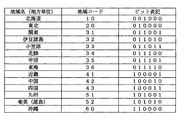
「第○地方」(○は、1、2、・・・、8の正整数が入る)は「地方単位」の地域であり、北海道、東北、関東、北陸、・・・といった地域コードの設定例とともに記述するような単位の地域である(図4参照)。図4の地域コード事例において、地域コードを単純な連番としていないのは、拡張性を持たせているためである。ここでは、地域コードに6ビットを割り当てている。 “Region ○” (where ○ is a positive integer of 1, 2,..., 8) is a “regional unit” region, and the region codes such as Hokkaido, Tohoku, Kanto, Hokuriku, etc. are set. This is the unit area as described with the example (see Figure 4). In the region code example of FIG. 4, the reason why the region code is not a simple serial number is that it has extensibility. Here, 6 bits are assigned to the area code.
「最大予測震度」は、震度4以上の4、5弱、5強、6弱、6強、7が相当する。「強」、「弱」を各々1、0と数値で区別し、各々を4ビットの「0100」、「0101」、「1101」、「0110」、「1110」、「0111」で区別して表記する。
The “maximum predicted seismic intensity” corresponds to
「到達予測時刻」は、地震の主要動が当該地域に到達する予測時刻を時、分、秒の単位で表したものであり、「到達予測差分時刻」(単に「差分時刻」と表記)は、第1地方の到達予測時刻との差分時刻である。第1地方は最も早く地震の主要動が到達する地点とし、第2地方以降は、正の値の遅延時間で地震の主要動が到達するものとする。 “Predicted arrival time” is the estimated time at which the main motion of the earthquake will reach the area in units of hours, minutes, and seconds, and “arrival predicted difference time” (simply expressed as “difference time”) is The difference time with the predicted arrival time in the first region. The first region is assumed to be the point where the main motion of the earthquake reaches the earliest, and after the second region, the main motion of the earthquake arrives with a positive delay time.
受信機1側で、「到達予測時刻」(第1地方以外は、第1地方の到達予測時刻に各地方の差分時刻を加算したもの)から現在時刻を差し引いた秒単位の時間を用いると、地震発生までの残時間として表示することができる。
On the
「到達予測時刻」は、12時間表記とし、時の表示は4ビット、分及び秒の表示は6ビットの数値として、例えば、10時25分37秒は「1010|011001|100101」(合計16ビット)と、時、分、秒の単位で各々2進数表示する。なお、「|」は時、分、秒の区別を見やすくするために、ここでの表記のみとして挿入しており、実際の伝送には挿入されない。 The “estimated arrival time” is expressed in 12 hours, the hour display is 4 bits, the minutes and seconds are 6 bits, for example, 10:25:37 is “1010 | 011001 | 100101” (total 16 Bit), and binary numbers in units of hours, minutes, and seconds. Note that “|” is inserted only as a notation here to make it easy to see the distinction between hour, minute, and second, and is not inserted in actual transmission.
「位相基準」及び「パリティビット」は、TMCC信号と同一とし、ISDB−T方式の地上デジタルテレビジョン放送の場合、そのOFDM方式の1シンボルを基準に、TMCC信号と同じ204シンボルにDBPSK信号の204ビットを割り振り、1フレームとする構成とする。よって、図2に記載の電文情報フォーマットの信号は、OFDM信号の2フレームで伝送される。尚、「パリティビット」は、例えば予め定めた差集合巡回符号方式に基づく誤り訂正のパリティビットが格納される。 The “phase reference” and the “parity bit” are the same as those of the TMCC signal, and in the case of ISDB-T terrestrial digital television broadcasting, based on one symbol of the OFDM method, the DBPSK signal has the same 204 symbols as the TMCC signal. 204 bits are allocated to form one frame. Therefore, the signal of the message information format shown in FIG. 2 is transmitted in two frames of the OFDM signal. The “parity bit” stores, for example, a parity bit for error correction based on a predetermined difference set cyclic code system.
「位相基準」は、TMCC信号と同様に、キャリア番号iのSP(Scattered
Pilot)信号に割り当てられるBPSK信号の値Wiと同じ生成多項式(x11+ x9+1)に基づく値が該当する。実施例1の電文情報の伝送には、ACキャリアを用いる。例えば、ISDB−T方式の地上デジタルテレビジョン放送波の部分受信セグメント(セグメント番号#0)におけるACキャリアは、モード3の同期変調部の場合、キャリア番号#7、#89、#206、#209、#226、#244、#377及び#407の8箇所にある。この8箇所のACキャリアが運ぶAC情報に記述の「位相基準」として格納されるWiは、各々0、0、0、1、1、1、1及び1である。尚、BPSK以外の変調方式を用いることもでき、前述の差集合巡回符号方式とともに、送信側及び受信側で予め利用する方式を定めておくようにする。
As with the TMCC signal, the “phase reference” is SP (Scattered) of carrier number i.
A value based on the same generator polynomial (x 11 + x 9 +1) as the value Wi of the BPSK signal assigned to the (Pilot) signal is applicable. An AC carrier is used for transmission of telegram information in the first embodiment. For example, the AC carrier in the partial reception segment (segment number # 0) of the ISDB-T terrestrial digital television broadcast wave is
よって、本発明による実施例1の送信装置は、このような電文情報(図2に示す電文情報のフォーマット)を用いることにより、受信側でフレーム同期の確立に関わらず検出することができる緊急警報放送又は緊急地震速報の有無の情報(起動・識別に関する情報)を受信機1に伝送でき、また、以下に説明する受信機1で必要とする「どれぐらいの規模/震度の地震がいつ起こるか」という情報の周知を速やかに、且つ、確実に行うことができる。
Therefore, the transmitting apparatus according to the first embodiment of the present invention uses such telegram information (the telegram information format shown in FIG. 2), so that an emergency alert that can be detected regardless of the establishment of frame synchronization on the receiving side. Information on the presence or absence of broadcast or earthquake early warning (information related to activation / identification) can be transmitted to the
次に、本発明による実施例1の受信機について説明する。 Next, the receiver of Example 1 by this invention is demonstrated.
前述したように、送信側では、緊急地震速報を含む電文情報(図2に示す電文情報のフォーマット)として、例えば地上デジタルテレビジョン放送の部分受信セグメント内の8本のACキャリアに、同期信号を兼ねる、緊急地震速報の有無を識別する「緊急地震速報用起動・識別フラグ」、緊急警報放送の有無を識別する「緊急警報放送用起動フラグ」、複数の地域を識別する地域コード、各地域における最大予測震度、及び各地域における予測到達時刻を含む緊急速報を誤り訂正のパリティ符号をつけて伝送する。 As described above, on the transmission side, as telegram information including the earthquake early warning (format of telegram information shown in FIG. 2), for example, synchronization signals are sent to eight AC carriers in a partial reception segment of digital terrestrial television broadcasting. Also, “Earthquake Early Warning Start / Identification Flag” that identifies the presence or absence of an Earthquake Early Warning, “Emergency Warning Broadcast Start Flag” that identifies the presence or absence of an emergency warning broadcast, a region code that identifies multiple regions, Emergency early warning including maximum predicted seismic intensity and predicted arrival time in each region is transmitted with parity code for error correction.
本発明による実施例1の受信機1は、図2に示す電文情報のフォーマットを受信する。ここで、受信機1は、携帯電話、携帯情報端末(PDA)、腕時計、置時計、パーソナルコンピュータ又は家電製品など、あらゆる機器に具備させることができるものである。
The
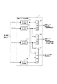
図5は、実施例1の受信機1のブロック図を示す。実施例1の受信機1は、アンテナ5と、AC受信部2と、AC情報解析部3と、同期保持・電源制御部4と、警告発生手段22と、電源回路21と、AC受信部2への電源供給の切り替えを行う第1の電源スイッチ19と、AC情報解析部3への電源供給の切り替えを行う第2の電源スイッチ20とを備える。
FIG. 5 is a block diagram of the
また、AC受信部2は、周波数変換回路6と、AD変換回路7と、FFT8と、AC抽出回路9と、相関演算回路10と、起動フラグ検出回路11と、フレーム同期検出回路12とを備える。
The
更に、AC情報解析部3は、誤り訂正回路16と、AC復号回路17と、情報処理回路18とを備える。
Further, the AC
情報処理回路18は、更に、位置検出手段及び現在時刻検出手段を備えることもできる。
The
同期保持・電源制御部4は、フレーム同期保持回路13と、タイミング制御回路14と、起動フラグ監視回路15とを備える。
The synchronization holding /
以下、図5に示す受信機1の各構成要素の機能を説明する。
Hereinafter, the function of each component of the
周波数変換回路6は、アンテナ5から入力された地上デジタルテレビジョン放送波のうち所定のフィルタにより不要な周波数成分を除去した後、指定されたチャンネルを選択し、中間周波信号に周波数変換するとともに適宜増幅して出力する回路である。このチャネル選択は、受信機にて予め定めておくこともできる。
The
AD変換回路7は、周波数変換回路6から出力される中間周波信号をデジタルに変換し、デジタルベースバンド信号を送出する。
The
FFT8は、OFDMシンボルの有効シンボル期間についてFFT(Fast Fourier Transform)演算を行い、OFDM形式のストリームに復調する。尚、有効シンボル期間は、ガードインタバル相関などによりシンボル同期を行って規定することができ、予め定めた伝送モードに従ったFFTサンプル周波数でFFT演算を行う。
The
AC抽出回路9は、OFDM形式のストリームからACキャリアを抽出し、DBPSK波から遅延検波した後、0又は1のレベル判定を行い、AC信号のビットストリームを得る。相関演算回路10へは、途中のOFDM形式のストリームから抽出されたACキャリア又はDBPSK波から遅延検波した直後のAC信号が供給される。また、レベル判定されたAC信号のビットストリームは、AC情報解析部3に供給される。
The
また、8箇所のACキャリアを用いてダイバシティ伝送を行う場合、該当する各々を受信して抽出した後、AC抽出回路9におけるレベル判定前か、又は相関演算回路10への入力前に加算することにより、信号の受信性能を向上し、確実な伝送を実現することもできる。
Also, when diversity transmission is performed using eight AC carriers, each corresponding signal is received and extracted, and then added before level determination in the
相関演算回路10は、OFDM形式のストリームから抽出されたACキャリア又はDBPSK波から遅延検波した後のAC信号(ダイバシティ受信をする場合は加算合成後のAC信号)を入力し、フラグの判定に必要な系統分のNビットの相関符号列により各々相関演算を行う。
ここで、フラグの判定に必要な系統分のNビットの相関符号列には、設定条件によりいくつかのパターンが存在するが、主となる条件で言えば、3つのフラグ、「緊急地震速報用起動・識別フラグ」、「緊急警報放送用起動フラグ」及び「その他のフラグ」の各々に関する組み合わせごとの符号列が該当する。図6に各フラグの組み合わせ事例と第1フレーム分(第2フレーム分は括弧内)の相関符号列とを合わせて示す。同図では、3つのフラグに対する全組み合わせを提示しているが、実際の伝送には使用しない組み合わせを含む。 Here, there are several patterns in the N-bit correlation code string for the system necessary for flag determination, depending on the setting conditions. In terms of the main conditions, there are three flags, “Earthquake Early Warning This corresponds to a code string for each combination of “start / identification flag”, “emergency warning broadcast start flag”, and “other flags”. FIG. 6 shows a combination example of each flag and a correlation code string for the first frame (the second frame is in parentheses). In the figure, all combinations for the three flags are presented, but combinations that are not used for actual transmission are included.
図7に相関演算回路10の一実施例を示す。
FIG. 7 shows an embodiment of the
この事例では、図6の3つのフラグの組み合わせのうち、緊急速報の実施される組み合わせの範囲を、(1)緊急警報放送のみ(符号列パターン1)、(2)緊急警報放送とその他(符号列パターン2)、(3)緊急地震速報のみ(符号列パターン3)、(4)いずれもなし(符号列パターン4)の4パターンがあるものとしている。 In this case, among the combinations of the three flags in FIG. 6, the range of the combination in which the emergency warning is implemented is (1) emergency warning broadcast only (code string pattern 1), (2) emergency warning broadcast and other (code It is assumed that there are four patterns of column pattern 2), (3) only the earthquake early warning (code string pattern 3), and (4) none (code string pattern 4).
図7に例示する相関演算回路10は、4系統のスライディング相関演算手段101,102,103,104と、4種類の符号列パターンに対応するパターン列を各々記憶する4系統のメモリ101a,102a,103a,104aとを備えて、入力されたAC信号を4系統に分配した後、各スライディング相関演算手段101,102,103,104と、対応する4系統のメモリ101a,102a,103a,104aの各々から読み出される符号列パターン1〜4の情報とにより、4種類の相関係数となる「フラグ1」、「フラグ2」、「フラグ3」及び「フラグ4」を計算して出力する。
The
スライディング相関演算手段101,102,103,104の各々は、1シンボル進めるごとに相関演算を実施し、相関係数の計算結果を出力する(図8(a)参照)。 Each of the sliding correlation calculation means 101, 102, 103, and 104 performs a correlation calculation every time one symbol is advanced, and outputs a correlation coefficient calculation result (see FIG. 8A).
ここでは、例えば1シンボルで伝送される1サンプルのAC信号の波形データを8ビットの数値で表現し、受信側で伝搬の影響を受けて受信されるACキャリアの振幅位相特性を反映した当該8ビットのサンプル数値に対し、相関演算を行うことを考える。 Here, for example, the waveform data of an AC signal of one sample transmitted by one symbol is expressed by an 8-bit numerical value, and the amplitude phase characteristic of the AC carrier received by the influence of propagation on the receiving side is reflected. Consider performing a correlation operation on bit sample values.
また、1段あたりの入出力で1シンボルの時間差がある(後述のフレーム同期保持回路と位相同期したシンボルクロックによりトリガされて1シンボルずつ保持するデータがレジスタ間をシフトしている)多段型のシフトレジスタ(図示せず)を用いる場合を考える。従って、8ビットの場合、相関演算を行うシンボル列の長さに対応する段数を有する多段型のシフトレジスタを8系統用いる。8系統の多段型シフトレジスタの1シンボルごとのシフトタイミングは、シンボル周期に同期して制御されており、各系統の入出力は、予め定められた最上位ビットから最下位ビットまでの順を常に維持している。 In addition, there is a time difference of one symbol at the input / output per stage (data that is held one symbol at a time triggered by a symbol clock that is phase-synchronized with a frame synchronization holding circuit described later is shifted between registers). Consider a case where a shift register (not shown) is used. Therefore, in the case of 8 bits, 8 multistage shift registers having the number of stages corresponding to the length of the symbol string for which the correlation operation is performed are used. The shift timing for each symbol of the 8-system multistage shift register is controlled in synchronization with the symbol period, and the input / output of each system is always in the order from a predetermined most significant bit to the least significant bit. Is maintained.
ここで、相関演算を行うシンボル列の長さは、先に示したフラグに与えられた符号列の長さであり、第1又は第2フレームのみの場合(図8(a)に図示する符号列200,200’)には、21である。このとき、シフトレジスタは20段あることになる。同様に、第1フレーム及び第2フレームを跨って相関演算を行う場合(図8(b)に図示する符号列201,202)には、相関演算のシンボル列の長さは21+204=225で、シフトレジスタの段数は224である。ただし、相関演算に寄与するのは最初の21段と最後の21段である(図8(b)参照)。
Here, the length of the symbol string for which correlation calculation is performed is the length of the code string given to the flag shown above, and in the case of only the first or second frame (the code shown in FIG. 8A). It is 21 in the
このため、スライディング相関演算手段101,102,103,104の各々は、この8系統の20段(又は224段)の多段型シフトレジスタを内蔵し、当該シフトレジスタの各入力及び各段の各出力は8系統分を合わせて各々8ビットの数値を表す。当該シフトレジスタの各段から出力される各8ビットの数値は、多段型シフトレジスタの各段の出力が有するシンボル遅延に該当する、符号列パターンのメモリに記憶された符号列の各ビットの値に基づき、各8ビットの数値の正負を反転(又は非反転)された後、全段数分合算される。尚、正負の反転は、2の補数に基づくものとし、演算の過程ではプラス4〜8ビットのマージンを許容する。
For this reason, each of the sliding correlation calculation means 101, 102, 103, and 104 incorporates eight systems of 20-stage (or 224-stage) multistage shift registers, and each input of each shift register and each output of each stage. Represents an 8-bit numerical value for each of the 8 systems. The 8-bit numerical value output from each stage of the shift register corresponds to the symbol delay of the output of each stage of the multistage shift register, and the value of each bit of the code string stored in the code string pattern memory Based on the above, the sign of each 8-bit value is inverted (or non-inverted), and then the total number of stages is added. The inversion of positive and negative is based on 2's complement, and a margin of
よって、スライディング相関演算手段101,102,103,104の各々は、入力の符号列パターンとメモリ内の符号列パターンが一致し、演算時の位相(時間)が一致(自己相関関係)する場合にピーク値を出力し、符号列パターンが一致しないか、又は、符号列パターンの位相(時間)にずれがある場合、0付近の値を出力する。 Therefore, each of the sliding correlation calculation means 101, 102, 103, 104 is used when the input code string pattern matches the code string pattern in the memory and the phase (time) at the time of calculation matches (autocorrelation). A peak value is output, and if the code string pattern does not match or there is a shift in the phase (time) of the code string pattern, a value near 0 is output.
4系統のスライディング相関演算手段101,102,103,104の各々は、各々異なる符号列パターンメモリから出力される符号列パターン1〜4に従って、シンボルごと相関演算を行い、各々結果を出力する。
Each of the four systems of sliding correlation calculation means 101, 102, 103, 104 performs a correlation calculation for each symbol in accordance with
符号列パターン1と接続するスライディング相関演算手段101は、「緊急警報放送用起動フラグ」のフラグ値のみが「1」となる場合に相関係数の演算結果にピーク値を出力する。この相関係数の演算結果は、「フラグ1」の信号として次段の起動フラグ検出回路11に入力される。同様に、符号列パターン2と接続するスライディング相関演算手段102は、「緊急警報放送用起動フラグ」及び「その他のフラグ」のフラグ値が揃って「1」となる場合に、相関係数の演算結果にピーク値を出力する。
The sliding correlation calculation means 101 connected to the
この相関係数の演算結果は、「フラグ2」の信号として次段の起動フラグ検出回路11に入力される。符号列パターン3と接続するスライディング相関演算手段103は、「緊急地震速報用起動・識別フラグ」のフラグ値のみが「1」となる場合に、相関係数の演算結果にピーク値を発生させる。この相関係数の演算結果は、「フラグ3」の信号として次段の起動フラグ検出回路11に入力される。そして、符号列パターン4と接続するスライディング相関演算手段104は、「緊急地震速報用起動・識別フラグ」、「緊急警報放送用起動フラグ」及び「その他のフラグ」のいずれのフラグ値も「0」である平常時の状態の場合に、相関係数の演算結果にピーク値を発生させる。この相関係数の演算結果は、「フラグ4」の信号として次段の起動フラグ検出回路11に入力される。
The correlation coefficient calculation result is input to the next-stage activation
図9に、相関演算回路10の一実施例における「フラグ1」信号の計算例を示す。
FIG. 9 shows a calculation example of the “
「緊急警報放送用起動フラグ」を検出する符号列パターン1(合計21ビット)に基づいてスライディング相関演算された「フラグ1」信号の出力信号には、図9(a)に示すように、当該「緊急警報放送用起動フラグ」が「1」であり、かつ当該「緊急地震速報用起動・識別フラグ」及び当該「その他のフラグ」は「0」であることを示す21ビットの符号列が送信された場合、最初のフレームの「位相基準」のサンプルを第0サンプル(=第0シンボル)としたときの第21サンプル(=第21シンボル)及び第429サンプルにピーク値が観測され、ピーク値が観測される間隔は、2フレーム(=408シンボル)となっている。一方、図9(b)に示すように、平常時のいずれのフラグも「0」である場合、「フラグ1」信号の出力信号には、特に目立ったピーク値が観測されない。
As shown in FIG. 9 (a), the output signal of the “
図9の相関係数の演算結果が示すように、本発明が開示する技術を用いると、フレームタイミングの検出と各種フラグの検出を同時にできる。 As shown in the correlation coefficient calculation result of FIG. 9, when the technique disclosed in the present invention is used, the detection of frame timing and the detection of various flags can be performed simultaneously.
なお、図9(c)が示すように、符号列パターンの長さが長いときには、短いときに比べて、符号列が一致しない時の相関係数の大きさを小さく抑えることができ、且つ、一致する時に大きくすることができることから、2フレームに跨る相関係数の演算を用いる224段のスライディング相関演算手段とするのが有効である。 As shown in FIG. 9C, when the length of the code string pattern is long, the correlation coefficient when the code strings do not match can be suppressed smaller than when the code string pattern is short, and Since it can be increased when they match, it is effective to use a 224-stage sliding correlation calculation means that uses the calculation of correlation coefficients over two frames.
図10に、起動フラグ検出回路15の一実施例を示す。
FIG. 10 shows an embodiment of the activation
図10に示す起動フラグ検出回路15は、4系統のレベル判定器151,152,153,154と3式のOR加算器155,156,157とから構成される。レベル判定器151,152,153,154の各々は、入力された信号の振幅値をシンボル毎に予め設定した閾値(相関係数の演算結果のピーク値が「1」となるように決める)と比較し、「1」と「0」を判定して、ピーク値を検出する当該シンボル期間出力する。OR加算器155,156,157は、論理和演算を行い、その演算結果を出力する。尚、ここでいう論理和演算は、次のような演算である。
The activation
0+0=0、0+1=1、1+0=1、1+1=1 0 + 0 = 0, 0 + 1 = 1, 1 + 0 = 1, 1 + 1 = 1
よって、起動フラグ検出回路15は、相関演算回路10が出力する4つのフラグ検出信号「フラグ1」〜「フラグ4」までを入力して、4系統のレベル判定器151,152,153,154の各々により各信号のフラグ値が「1」であるか、又は「0」であるかを決定し、続く3式のOR加算器155,156,157の各々により「緊急警報放送用起動フラグ」、「緊急地震速報用起動・識別フラグ」及び「その他のフラグ」の各々の機能に対応する信号ごとに分離して、起動フラグ監視回路15の(緊急警報放送)向け信号、起動フラグ監視回路15の(緊急地震速報、その他)向け信号、フレーム同期検出回路12の同期検出向け信号に変換して、各信号を該当する回路へ出力する。
Therefore, the activation
ここで、起動フラグ監視回路15の(緊急警報放送)向け信号は、「フラグ1」信号のレベル判定器151の出力と、「フラグ2」信号のレベル判定器152の出力とが入力され、且つ論理和演算を行うOR加算器155の出力であり、「緊急警報放送用起動フラグ」のフラグ値が「1」の場合、所定のシンボル期間、「1」を出力する。起動フラグ監視回路15を経て、受信機1の端末が別に備える地上デジタルテレビジョン放送の受信機(図示しない番組視聴用の受信機を指す。なお、本発明の受信機1を内蔵する場合は、その本体の受信機)に接続され、当該地上デジタルテレビジョン放送の受信機が起動していない場合に、当該地上デジタルテレビジョン放送の受信機を起動させる電源供給の切り替えを行う、図示しない電源スイッチの制御信号となる。
Here, the signal for the (emergency warning broadcast) of the activation
起動フラグ監視回路15の(緊急地震速報、その他)向け信号は、「フラグ2」信号のレベル判定器152の出力と「フラグ3」信号のレベル判定器153の出力とが入力され、且つ論理和演算を行うOR加算器156の出力であり、「緊急地震速報用起動・識別フラグ」または「その他のフラグ」が示すフラグ値が「1」の場合、所定のシンボル期間、「1」を出力する。起動フラグ監視回路15へ入力され、第1の電源スイッチ19と第2の電源スイッチ20の制御に寄与する。
As for the signal for the emergency flag (Earthquake Early Warning, etc.) of the activation
起動フラグ監視回路15の同期検出向け信号は、「フラグ1」信号〜「フラグ4」信号の全入力に対するレベル判定器151,152,153,154の出力が各々入力され、且つ論理和演算を行うOR加算器157の出力であり、フレーム同期検出回路12に入力される。全てのフラグの組み合わせにおいて、2フレーム毎又は1フレーム毎に(ただし、これは、Nビットの符号列と相関演算回路10の構成に依存する。例えば、図6の符号列をそのまま相関演算回路10の符号列パターンに用いた場合には2フレーム毎となる。)「各種フラグ(同期信号)」の最後のシンボルで、フラグ値「1」を出力する。
As the signal for synchronization detection of the start
フレーム同期検出回路12は、起動フラグ検出回路11の同期検出向け信号の出力を入力し、起動フラグ検出回路11の出力に2フレーム毎又は1フレーム毎に検出されるフラグ値「1」の発生周期に基づき、例えばAC信号のフレームの先頭のタイミングでフレーム同期信号(リセットパルス)を発生する。また、フレーム同期信号に基づいて緊急速報のフレーム同期確立の有無を示す緊急速報同期確立情報を生成する。
The frame synchronization detection circuit 12 receives the output of the synchronization detection signal from the activation
同期保持・電源制御部4におけるタイミング制御回路14及びフレーム同期保持回路13は、常時、電源回路21から給電されている。
The
フレーム同期保持回路13は、例えばクロック発生器とカウンタで構成され、クロック発生器で発生したクロックをカウンタでカウントし、カウント値が所定値となる毎にフレームパルスを発生すると共にカウント値をフレーム同期信号(リセットパルス)に従ってリセットし、このフレームパルスをタイミング制御回路14に供給する。これにより、フレーム同期保持回路13は、自己保持したフレームパルスを発生させることができる。
The frame
タイミング制御回路14は、フレーム同期保持回路13からのフレームパルスと、フレーム同期検出回路12からの緊急速報同期確立情報とに基づいて、後述するフレーム間間欠受信モードか、又はフレーム内間欠受信モード、或いはこれらの組み合わせの間欠受信モードを随意決定し、各間欠受信モードのタイミングでオン/オフ(0又は1の値)の制御信号を送出する。
Based on the frame pulse from the frame
起動フラグ監視回路15は、起動フラグ検出回路11から2系統の各種フラグ信号(本実施例では、主として「緊急警報放送用起動フラグ」と「緊急地震速報用起動・識別フラグ」又は「その他のフラグ」)を取得して、タイミング制御回路14からの制御信号のタイミング(「位相基準」に続く「各種フラグ(同期信号)」のNビットの符号列の先頭のシンボル)で、各種フラグの値(相関演算の結果)を監視する。
The start
起動フラグ監視回路15は、起動フラグ検出回路11から入力した2系統の各種フラグ信号のうち「緊急警報放送用起動フラグ」に関する信号の値が、平常時の「0」の状態から、緊急警報放送がある旨を示すフラグ値「1」に変更されるか否かを監視し、「1」のフラグ値を判別した場合には、受信機1の端末が別途備える地上デジタルテレビジョン放送の受信機(前述の、図示しない番組視聴用の受信機を指す。)に、当該フラグ値に基づく制御信号を送出する。つまり、当該地上デジタルテレビジョン放送の受信機が起動していない場合に、当該地上デジタルテレビジョン放送の受信機を起動させる電源供給の切り替えを行う電源スイッチをオンとし、当該地上デジタルテレビジョン放送の受信機による緊急警報放送の受信を可能とする。また、該地上デジタルテレビジョン放送の受信機が緊急警報放送を受信しない別の放送を視聴している場合には、予め受信機のユーザによる選択に基づいて設定した条件により緊急警報放送を受信できるチャンネルへの切り替えを行うチャンネル切り替えスイッチを制御する。
The start
それとは逆に、起動フラグ監視回路15は、緊急警報放送がある旨を示すフラグ値「1」から、平常時の「0」の状態に変更される状態を判別した場合には、タイミング制御回路14からの制御信号のタイミングで、各種フラグのフラグ値のみを常時監視するように、前記地上デジタルテレビジョン放送の受信機を起動した場合には、予め予約した受信機のユーザによる選択に基づいて当該地上デジタルテレビジョン放送の受信機への電源供給を遮断する。また、緊急警報放送を受信できるチャンネルへの当該地上デジタルテレビジョン放送の受信機のチャンネル切り替えを行った場合には、受信機のユーザによる選択に基づいて緊急警報放送を受信する前に受信していたチャンネルにチャンネル切り替えを行う。
On the other hand, when the activation
一方で、起動フラグ監視回路15は、起動フラグ検出回路11から入力した2系統の各種フラグ信号のうち「緊急地震速報用起動・識別フラグ」又は「その他のフラグ」に関する信号の値が、平常時の「0」の状態から、緊急地震速報がある旨またはその他の緊急速報がある旨を示すフラグ値「1」に変更されるか否かを監視し、「1」のフラグ値を判別した場合には、間欠受信モードを解除し、AC受信部2への電源供給を連続して行うように第1の電源スイッチ19の切り替えを行うとともに、AC情報解析部3への電源供給を行うように第2の電源スイッチ20を切り替え、AC信号に含まれるその他の各種フラグの情報及び緊急地震速報など電文情報の復号を行う。
On the other hand, the activation
このとき、平常時の起動フラグ監視回路15は、タイミング制御回路14からの制御信号に基づき第1の電源スイッチ19のオン/オフを切り替えて、AC受信部2の電源供給を制御している。また、起動フラグ監視回路15は、第2の電源スイッチ20を平常時にはオフとしてAC情報解析部3への電源供給を遮断している。
At this time, the normal startup
それとは逆に、起動フラグ監視回路15は、緊急地震速報又はその他の緊急速報がある旨を示すフラグ値「1」から、平常時の「0」の状態に変更される状態を判別した場合には、タイミング制御回路14からの制御信号のタイミングで、各種フラグのフラグ値のみを常時監視するように、AC受信部2への電源供給を第1の電源スイッチ19によって制御するとともに、AC情報解析部3への電源供給を遮断するように第2の電源スイッチ20の切り替えを行う。
On the contrary, the activation
このように、起動フラグ監視回路15は、平常時には、各種フラグのフラグ値のみを常時監視するように動作する。
In this way, the activation
これにより、極めて消費電力を節約しながら、緊急速報の情報を確実に、且つ即時に取得できるようになる。 As a result, it is possible to reliably and immediately obtain emergency bulletin information while significantly saving power consumption.
尚、起動フラグ監視回路15は、緊急速報の全ての情報のみを取得するように、フレーム内間欠受信動作又はフレーム間間欠受信動作で、AC情報解析部3に電源供給するように制御することもできる。特に、フレーム間間欠受信動作で動作する場合に、誤り訂正回路16にて、複数のフレーム間で多数決判定した結果を送出するように動作させることもできる。
The activation
AC情報解析部3は、AC情報解析部3への電源供給が為された場合に、フレーム同期検出回路12によって生成されたフレーム同期信号(即ち、図5ではフレーム同期保持回路13の出力)に同期して、誤り訂正回路16がAC信号を誤り訂正し、AC復号回路17は送信側の符号化方式に対応する復号形式で各種フラグ以降の内容(AC信号の電文情報)を復号し、各種フラグのその他の情報及びAC信号の電文情報が格納する緊急地震速報の情報、即ち「緊急地震速報」の内容を出力する。
The AC
「その他のフラグ」が「1」を示す符号列であり、例えば「津波」の警報が出ている場合には、情報処理回路18は、例えば「緊急警報放送(津波警報)」といったメッセージを作成し、津波警報に基づく緊急警報放送の視聴を警告発生手段22に表示して受信機1のユーザに知らせる。
When the “other flag” is a code string indicating “1”, for example, when a “tsunami” warning is issued, the
また、「緊急地震速報用起動・識別フラグ」が「1」を示す符号列である場合には、情報処理回路18は、AC復号回路17が出力した「緊急地震速報」に基づき、例えば「緊急地震速報:○○地域で強い揺れに警戒してください」や「緊急地震速報:○○県でマグニチュード△△の強い地震が発生。強い揺れに警戒」などのメッセージを作成する。
When the “emergency earthquake early warning start / identification flag” is a code string indicating “1”, the
尚、電文情報がISDB−T方式の地上デジタルテレビジョン放送波の部分受信セグメントにおけるモード3の同期変調モードにて受信可能なように設定されている場合で、同一内容の緊急速報が8本のACキャリアにて伝送されるように予め規定されている場合には、AC復号回路17は、AC抽出回路9又は誤り訂正回路16にて、相関演算回路10が行うのと同様にダイバシティ利得を得るために該8本のACキャリアから、当該緊急速報を復号することもできる。
In the case where the telegram information is set so as to be received in the synchronous modulation mode of
或いは又、電文情報が、予め定めた差集合巡回符号方式のパリティビットを含んでいる場合に、誤り訂正回路16にて、該差集合巡回符号方式に基づく誤り訂正を行って、AC復号回路は、当該緊急速報を復号する。
Alternatively, when the telegram information includes a parity bit of a predetermined difference set cyclic code system, the
このように、本発明に係る受信機1においては、AC情報の誤りを検出又は訂正し、復号する様々な態様が考えられ、「復号手段」として総括して説明する。
As described above, in the
情報処理回路18は、復号した緊急速報から「緊急地震速報」の場合には、各地域の震度及び到達予測時間の予測情報を計算する場合もある。例えば、緊急速報における地域コード、予測震度情報及び予測到達時間情報、及び、現在位置及び現在時刻の情報から、当該受信機の位置する地域の震度及び到達予測時間の予測情報を計算して、受信機1に特化した緊急速報の速報文を作成する。
In the case of “Emergency Earthquake Early Warning” from the decoded emergency early warning, the
この場合、情報処理回路18は、現在位置を得る手段としての位置検出手段と、現在時刻を得る手段としての現在時刻検出手段とを有するように構成することもできる(図示せず)。
In this case, the
当該位置検出手段は、当該受信機の地域的な位置を表す位置情報を検出する。好適に、位置検出手段は、固定受信においては設置時の受信機のユーザによる入力或いはGPS(Global Positioning System)による位置検出、或いは受信している地上デジタルテレビジョン放送波の受信信号に含まれるNIT(Network Information Table)に基づく放送局の識別(ネットワーク識別)等により、移動又は携帯受信においては、GPSによる位置検出或いは地上デジタルテレビジョン放送の受信信号に含まれるNITに基づく放送局の識別、或いは携帯電話の場合基地局情報、無線LANの場合ホットスポット情報(場所を認識可能な場合、場所の手入力も含む)などにより自身の位置を検出することができる。 The position detection means detects position information representing the regional position of the receiver. Preferably, in the fixed reception, the position detection means is input by the user of the receiver at the time of installation, position detection by GPS (Global Positioning System), or NIT included in the received signal of the terrestrial digital television broadcast wave being received. For mobile or mobile reception, such as identification of a broadcast station based on (Network Information Table) (network identification), or the like, or identification of a broadcast station based on NIT included in a received signal of terrestrial digital television broadcast, In the case of a mobile phone, its own position can be detected from base station information, in the case of a wireless LAN, hot spot information (including a manual location input if the location can be recognized), and the like.
当該現在時刻検出手段は、当該受信機の現在時刻を表す現在時刻情報を検出する。好適に、現在時刻検出手段は、受信機のユーザの入力による時刻設定、標準電波(電波時計、JJY)、GPS、或いは受信している地上デジタルテレビジョン放送波の受信信号に含まれるTDT(Time Date Table)などから現在時刻情報を検出することができる。或いは、現在時刻検出手段は、受信機が携帯電話に具備される場合、基地局からの信号により現在の時刻を検出することができる。 The current time detection means detects current time information indicating the current time of the receiver. Preferably, the current time detection means includes a time setting by a user input of the receiver, a standard radio wave (radio clock, JJY), GPS, or a TDT (Time signal included in a received signal of a terrestrial digital television broadcast wave received. Current time information can be detected from (Date Table) or the like. Alternatively, the current time detection means can detect the current time based on a signal from the base station when the receiver is provided in a mobile phone.
警告発生手段22は、情報処理回路18が抽出して作成した速報文を提示する。例えば、警告発生手段22は、当該受信機がテキスト表示器を有する場合はテキスト表示により「緊急地震速報(気象庁):強い揺れに警戒。○○地方、△△地方」などと提示する。当該受信機がスピーカを有する場合は、警報音とともに同様の速報文を読み上げる音声を出力する。また、当該受信機1がバイブレータを有する場合は、通常動作時とは異なる動作で知覚的に警告を発生するように振動警告を発するか、又は振動警告により図示しない表示器やスピーカへ注意を促す。或いは又、当該受信機1が携帯電話、携帯情報端末(PDA)、腕時計、置時計、パーソナルコンピュータ等の何らかの機器に具備される場合には、これらの機器の機能を用いて、スピーカから音で発生させるか、バイブレータによる振動警告を発するか、又は通常動作時とは異なる動作で知覚的に警告を発生するようにすることもできる。
The warning generation means 22 presents a quick report sentence extracted and created by the
ここで、フレーム間間欠受信モードとフレーム内間欠受信モードについて説明する。 Here, the interframe intermittent reception mode and the intraframe intermittent reception mode will be described.
間欠受信モードを利用すれば、受信機の消費電力を大幅に低減することができる。 If the intermittent reception mode is used, the power consumption of the receiver can be significantly reduced.
更にAC信号の同期確立の信頼性を高める場合に、好適に、フレーム間間欠受信モードを用いることができる。或いは又、AC信号の同期確立の信頼性がある場合にも誤りを検出して多数決判定するためにフレーム内間欠受信モードを用いることもできる。 Further, in order to improve the reliability of AC signal synchronization establishment, the inter-frame intermittent reception mode can be preferably used. Alternatively, the intra-frame intermittent reception mode can also be used to detect an error and make a majority decision even when the AC signal synchronization is reliable.
フレーム間間欠受信モードは、例えば、AC信号の同期が未確立を示す緊急速報同期確立情報を供給されている場合に決定される。この場合、第1の電源スイッチのオン継続時間は、最低1フレーム以上とする。例えば、1フレームのみを用いる場合には、受信機1の消費電力を大幅に低減することができる。更に、例えば2フレームを用いる場合には、偶数パリティを利用して、受信信号の信頼性を高めることができる。或いは又、例えば3フレームを用いる場合には、多数決判定して、受信信号の信頼性を高めることができる。
The inter-frame intermittent reception mode is determined, for example, when emergency early warning synchronization establishment information indicating that AC signal synchronization is not established is supplied. In this case, the ON duration of the first power switch is at least one frame. For example, when only one frame is used, the power consumption of the
尚、奇数フレーム(上述の第1フレーム)と偶数フレーム(同第2フレーム)とでは、両フレームを分離して受信できることから、対応する相関符号列が異なるように構成するのが好適である。また、偶数パリティによる判定或いは多数決判定は、各々の符号列による相関係数の結果として現れるピーク値の検出の有無に基づいて行うことができる。 It should be noted that since odd frames (the above-mentioned first frame) and even frames (the second frame) can be received separately, it is preferable that the corresponding correlation code strings are different. Further, the determination based on the even parity or the majority determination can be performed based on whether or not a peak value appearing as a result of the correlation coefficient by each code string is detected.
尚、地上デジタルテレビジョン放送の送信モードがモード3でガードインタバル比(GI比)1/8の場合、1フレームは231.336msecである。また、フレーム間間欠受信モードではAC受信部2の電源投入タイミングの制約はなく、例えばオン/オフ間隔は所定値(例えば10秒間隔)とする。
If the transmission mode of terrestrial digital television broadcasting is
このように、AC信号の同期未確立時のAC受信部2への電源供給時間を1フレーム以上とすることで、AC信号の取りこぼしを防止することができ、受信信号の信頼性を高めることができる。また、オン/オフ間隔を長くすることで待機消費電力を低減することもできる。
Thus, by setting the power supply time to the
また、フレーム内間欠受信モードは、例えば、AC信号の同期が確立していることを示す緊急速報同期確立情報を供給されている場合に決定される。この場合、第1の電源スイッチのオン継続時間は、例えば30.618msec=(27/204)フレームとし、AC信号の前のフレームの最後のシンボルから電源を投入し、所要のビット、例えば「各種フラグ(同期信号)」の最後のシンボルが受信された時点で電源を遮断する。 The intra-frame intermittent reception mode is determined, for example, when emergency early warning synchronization establishment information indicating that AC signal synchronization is established is supplied. In this case, the ON duration of the first power switch is, for example, 30.618 msec = (27/204) frame, the power is turned on from the last symbol of the frame before the AC signal, and the required bits, for example, “various” When the last symbol of the “flag (synchronization signal)” is received, the power is shut off.
このように、AC信号の同期確立時のAC受信部2への電源供給時間を27シンボルとすることで、待機消費電力を低減させることができる。
Thus, the standby power consumption can be reduced by setting the power supply time to the
以下、更に詳細に本発明による実施例1の受信機の受信動作について説明する。 Hereinafter, the receiving operation of the receiver according to the first embodiment of the present invention will be described in more detail.
まず、実施例1の受信機1は、AC受信部2により、選択されたチャンネルにて受信したOFDM信号からガードインタバル相関などによりシンボル同期を行い、FFT演算を経てAC信号を抽出する。
First, the
更に、実施例1の受信機1は、AC受信部2により、電文情報(図2に示す電文情報のフォーマット)に含まれる、AC信号に多重された「各種フラグ(同期信号)」に基づき、AC信号のフレーム同期を行う。
Furthermore, the
そして、実施例1の受信機1は、フレーム同期に基づいて得られたタイミングに従い、電文情報(図2に示す電文情報のフォーマット)に含まれる、DBPSK復調されるACキャリアからのAC信号と、「各種フラグ(同期信号)」中の「緊急警報放送用起動フラグ」、「緊急地震速報用起動・識別フラグ」及び「その他のフラグ」の各フラグの組み合わせに基づく相関符号列との相関演算により検出される相関係数のピーク値を、起動フラグ監視回路15によって監視する。
Then, according to the timing obtained based on the frame synchronization, the
「緊急警報放送用起動フラグ」が「1」のときには、受信機1は、当該受信機1が別途備える図示しない地上デジタルテレビジョン放送の受信機が起動していない場合に、当該地上デジタルテレビジョン放送の受信機を起動させる電源供給の切り替えを行う電源スイッチをオンとし、当該地上デジタルテレビジョン放送の受信機による緊急警報放送の受信を可能とする。
When the “emergency warning broadcast activation flag” is “1”, the
また、受信機1は、該地上デジタルテレビジョン放送の受信機が緊急警報放送を受信しない別の放送を視聴している場合には、予め受信機のユーザによる選択に基づいて設定した条件により緊急警報放送を受信できるチャンネルへの切り替えを行うチャンネル切り替えスイッチを制御する。
In addition, when the receiver of the terrestrial digital television broadcast is watching another broadcast that does not receive the emergency warning broadcast, the
一方、受信機1は、「緊急地震速報用起動・識別フラグ」又は「その他のフラグ」が「1」のときには、以後に続く電文情報をAC情報解析部3によって受信し、残る「各種フラグ(同期信号)」のフラグを確認し、「その他のフラグ」が「1」のときに「津波」のフラグ(図3の「各種フラグ(同期信号)」における「リザーブビット(フラグ)」内で設定するものとする。)が「1」となっているときには、AC情報解析部3において「津波警報」への注意を促す速報文を作成し、警告発生手段22により、受信機1(又は該受信機1を具備する機器)が有する表示器上に表示する。或いは同時に、警告音又は音声、或いはその双方を受信機(又は該受信機を具備する機器)が有するスピーカから発する。
On the other hand, when the “emergency earthquake early warning start / identification flag” or “other flags” is “1”, the
また、受信機1は、「緊急地震速報用起動・識別フラグ」が「1」のときには、地域コードをまず認識する。
The
一方で、受信機1は、当該受信機1の地域的な位置を表す位置情報を検出する位置検出手段を有することができ、自身の位置を認識することができる。
On the other hand, the
また、受信機1は、当該受信機1の現在時刻を表す現在時刻情報を検出する現在時刻検出手段を有することができ、現在の時刻を認識することができる。
In addition, the
受信機1は、前記自身の受信機の位置が地域コードに記載の地域と一致か、又は含まれる場合、続いて読み出される震度情報及び到達予測時刻を取得する。
The
続いて、受信機1は、情報処理回路18により、取得した到達予測時刻と当該現在の時刻との差を計算する。
Subsequently, the
そして、受信機1は、警告発生手段22により、計算した震度情報、及び到達予測時刻の現在時刻からの時間差をテキスト文字に変換して、受信機1(又は該受信機1を具備する機器)が有する表示器上に表示する。或いは同時に、警告音又は音声、或いはその双方を受信機1(又は該受信機1を具備する機器)が有するスピーカから発する。これらの表示又は音により、受信機1のユーザは、地震の発生及び予測時間を知ることができる。尚、警告発生の方法は、これらに限定するものではなく、アナログ時計の秒針を擬態して知らせるなどもある。
Then, the
図2の電文情報フォーマットは、204シンボルを1フレームとした2フレームにより最大8つの地域の情報を伝送する。ISDB−T方式の地上デジタルテレビジョン放送のモード3、ガードインタバル比1/8の場合、1フレームの長さは0.231秒であるので、この2フレームを受信するのに少なくとも0.5秒程度の時間は必要である。
The telegram information format of FIG. 2 transmits information of up to eight regions by two frames with 204 symbols as one frame. In the case of ISDB-T terrestrial digital
緊急地震速報が出て、放送局が電波に載せる時間並びに送信と受信のタイミングのずれを考慮しても、放送局からの送出、受信機での「各種フラグ(同期信号)」検出、緊急速報の読み出しまでが2〜3秒程度で可能となり、速やかな緊急地震速報の伝送が可能となる。 Even if the earthquake early warning is issued and the broadcast station puts it on the radio wave and the timing of transmission and reception is taken into account, transmission from the broadcast station, detection of various flags (synchronization signals) at the receiver, emergency early warning Can be read out in about 2 to 3 seconds, and prompt earthquake early warning transmission is possible.
更に、この2フレームとした電文情報フォーマットを2組のACキャリアに分けて各々を同一のフレームで伝送すれば、1フレームでの同期の検出と緊急速報の読み出しの工夫により0.2〜0.5秒程度の時間を短縮することができる。 Furthermore, if the two-frame telegram information format is divided into two sets of AC carriers and each of them is transmitted in the same frame, 0.2-0. The time of about 5 seconds can be shortened.
一方、送信側でAC信号の8系統、又は4系統ずつに同じ緊急地震速報に関する情報を載せて伝送することもでき、受信側で全キャリアのDBPSK復調を行い、レベル判定後に多数決により、或いはアナログ振幅レベルで合成してレベル判定することにより、ダイバシティ利得が得られ、より低い受信電力での受信が可能となり、確実な伝送が可能となる。 On the other hand, it is possible to transmit the information related to the same earthquake early warning on each of the 8 or 4 AC signal lines on the transmitting side, and perform DBPSK demodulation on all carriers on the receiving side and perform majority determination after level judgment or analog By combining the amplitude levels and determining the level, diversity gain is obtained, reception with lower received power is possible, and reliable transmission is possible.
更に、奇数フレームと偶数フレームとに各々対応する相関符号列を用いて相関係数を計算し、2フレームにわたって「各種フラグ(同期信号)」の相関ピーク値を監視し、その結果を偶数パリティとすることにより、受信した各種フラグの信頼度を高めることもできる。或いは3フレームにわたって「各種フラグ(同期信号)」の相関ピーク値を監視し、その結果を多数決判定することにより、受信した各種フラグの信頼度を高めることもできる。 Furthermore, correlation coefficients are calculated using correlation code sequences corresponding to odd frames and even frames, and the correlation peak values of “various flags (synchronization signals)” are monitored over two frames. By doing so, the reliability of the received various flags can be increased. Alternatively, the correlation peak value of “various flags (synchronization signal)” is monitored over three frames, and the reliability of the received various flags can be increased by determining the majority of the results.
また、204ビットの伝送において、82ビットはパリティビットである。例えば、ISDB−T方式のTMCC信号と同様に、対象とするビット数は異なるが、差集合巡回符号(273、191)の短縮符号を用いて誤り訂正符号化するなどして伝送することにより、少なくとも8ビットの誤り訂正が可能となるので、より信頼度を高めることができる。 In the 204-bit transmission, 82 bits are parity bits. For example, as with the TMCC signal of the ISDB-T system, the number of target bits is different, but by performing error correction encoding using a shortened code of the difference set cyclic code (273, 191) and the like, Since at least 8-bit error correction is possible, the reliability can be further increased.
前述したように、例えばISDB−T方式の地上デジタルテレビジョン放送波を受信する携帯電話に本受信機1を適用した場合に、当該携帯電話が電力節約のために待機モードにあるときに、待機電力を少なくして緊急警報放送又は緊急地震速報が発せられたタイミングで速やかに受信機1を起動することが必要である。
As described above, when the
本実施例の受信機1においては、図2の電文情報フォーマットの場合、フレーム同期の確立後、1フレームの最後のビットで、緊急速報検出用として機能する受信機1のAC受信部2に電源供給し、「各種フラグ(同期信号)」の最後のビット(26ビット目)で電源を落とすように構成するため、より一層の低消費電力化を実現することができる。
In the
従って実施例1の受信機1の構成であれば、緊急速報、特に緊急地震速報が発せられたときには、AC受信部2の電源の投入を継続し、AC情報解析部3の電源を即時に投入することで、速やかに緊急地震速報に基づく情報を受信機1のユーザに伝えることができるようになる。
Therefore, with the configuration of the
次に、本発明による実施例2の送信装置及び受信機について説明する。 Next, a transmitter and a receiver according to a second embodiment of the present invention will be described.
(実施例2)
本発明による実施例2の送信装置及び受信機のハードウェアの構成要素は、実施例1と同様であるが、電文情報フォーマットの態様が相違しており、これに起因して情報処理回路18の動作が相違する。従って、実施例1と同様な構成要素のより詳細な説明は省略する。本実施例の説明においても、ISDB−T方式の地上デジタルテレビジョン放送におけるモード3のACキャリアが運ぶAC情報の全てを用いる場合について説明するが、他のモードにおいても適用可能であることに留意する。
(Example 2)
The components of the hardware of the transmission apparatus and receiver according to the second embodiment of the present invention are the same as those of the first embodiment, but the aspect of the message information format is different. The operation is different. Therefore, a more detailed description of the same components as those in the first embodiment is omitted. Also in the description of the present embodiment, a case will be described in which all AC information carried by the
実施例1の電文情報フォーマットは、送信装置が送信する電文情報、特に緊急地震速報時の電文情報において、直接該当する地域と震度、到達予測時間を伝える場合を提示した。この場合、受信機の負荷を抑えて速やかに当該緊急地震速報を伝えることができるが、地域の枠組みを一定以上に細かく伝えることができない。また、2フレームによる伝送を必要とするため、1フレームのみで伝える場合に比べて遅延が増える、或いは伝送のために必要な受信電力が増える。 The message information format of the first embodiment presents a case in which the corresponding area, seismic intensity, and predicted arrival time are directly communicated in the message information transmitted by the transmitting device, particularly the message information at the time of the earthquake early warning. In this case, the earthquake early warning can be transmitted promptly while suppressing the load on the receiver, but the regional framework cannot be communicated more precisely than a certain level. Further, since transmission by two frames is required, the delay is increased or reception power necessary for transmission is increased as compared with the case of transmitting by only one frame.
そこで、受信機1において、例えば非特許文献1に示される震度や到達時刻の予測のための演算処理を大きな負荷なく実行できることを想定した電文情報フォーマットとするのが望ましい。即ち、送信する緊急速報の電文情報を減らして、1フレームに限定しての電文情報の伝送を可能とする電文情報フォーマットとするのが望ましい。
Therefore, it is desirable that the
そのため、実施例2では、別の電文情報フォーマットを提示する。図11に、受信機において最大予測震度と到達予測時刻の算出を行う場合の実施例2の電文情報のフォーマット例を示す。尚、実施例2の受信機は、実施例1と同様に、携帯電話、携帯情報端末(PDA)、腕時計、置時計、パーソナルコンピュータ又は家電製品など、あらゆる機器に具備させることができるものである。 Therefore, in Example 2, another message information format is presented. FIG. 11 shows a format example of the telegram information in the second embodiment when the receiver calculates the maximum predicted seismic intensity and the predicted arrival time. Note that the receiver of the second embodiment can be installed in any device such as a mobile phone, a personal digital assistant (PDA), a wristwatch, a table clock, a personal computer, or a home appliance as in the first embodiment.
図11は、地震の発生時刻、震源の位置(緯度、経度、深さ)及びマグニチュードの情報を格納して伝送するフォーマットである。 FIG. 11 shows a format for storing and transmitting information on the occurrence time of an earthquake, the position of the epicenter (latitude, longitude, depth) and magnitude information.
ここで、「位相基準」は、図2の電文情報フォーマットで用いられているものと同じである。ここでは、動作も含め内容が同一であるので、詳細な記載を省略する。 Here, the “phase reference” is the same as that used in the message information format of FIG. Here, since the contents including the operation are the same, detailed description is omitted.
「各種フラグ(同期信号)」は、本発明が開示する緊急速報を受信するための起動フラグの送受信方法の主たる部分を表し、「緊急警報放送用起動フラグ」、「緊急地震速報用起動・識別フラグ」、「その他のフラグ」、「通常」/「訓練」の識別、緊急速報の「キャンセル」などの情報を提示するNビットの符号列である。実施例2においても、実施例1の図2の電文情報フォーマットで使用する「各種フラグ(同期信号)」と同じもの(図3)を使用することができる。 “Various flags (synchronization signals)” represent the main part of the transmission / reception method of the activation flag for receiving the emergency bulletin disclosed in the present invention, “emergency warning broadcast activation flag”, “emergency earthquake bulletin activation / identification This is an N-bit code string that presents information such as “flag”, “other flags”, “normal” / “training” identification, and “cancel” for emergency bulletin. Also in the second embodiment, the same “various flags (synchronization signals)” (FIG. 3) used in the message information format of FIG. 2 of the first embodiment can be used.
ただし、ここでは別のフォーマット例を示す。26ビットの「各種フラグ(同期信号)」の符号列のうち、Nビットの符号列に相当する21ビットを、例えば生成多項式(x5+ x2+1)で発生される31ビットのビット列から例えば21ビット分だけ抜き出した事例である。当該事例を図12に示す。ビット列「001101001000010101110」を連続する7ビットずつに分けて、3つのフラグ、つまり、「緊急地震速報用起動・識別フラグ」、「緊急警報放送用起動フラグ」及び「その他のフラグ」、の各々のフラグ値が「1」の場合としている。尚、フラグ値「0」は、この各位相の反転したものとする。 However, another format example is shown here. Of the 26-bit “various flags (synchronization signal)” code string, 21 bits corresponding to an N-bit code string are obtained from, for example, a 31-bit bit string generated by a generator polynomial (x 5 + x 2 +1). In this example, only 21 bits are extracted. This case is shown in FIG. The bit string “001101001000010101110” is divided into 7 consecutive bits, and each of three flags, ie, “emergency earthquake warning start / identification flag”, “emergency warning broadcast start flag”, and “other flags” The value is “1”. The flag value “0” is obtained by inverting each phase.
「各種フラグ(同期信号)」の残るフラグは、図2の電文情報フォーマットのものと同一である。つまり、「通常」/「訓練」の識別、緊急速報の「キャンセル」の各1ビット、「リザーブビット(フラグ)」の3ビットである。これについては、実施例1と同様であるため、詳細な説明は省略する。 The remaining flags of “various flags (synchronization signals)” are the same as those in the message information format of FIG. That is, there are 1 bit each for “normal” / “training” identification, “cancel” for emergency bulletin, and 3 bits for “reserve bit (flag)”. Since this is the same as in the first embodiment, detailed description thereof is omitted.
尚、図11の電文情報フォーマットを用いる実施例2では、1フレームで必要な緊急速報を伝送することができるため、1フレーム分の電文情報フォーマットのみを示している。ただし、「各種フラグ(同期信号)」を第1フレームと第2フレーム、或いは奇数フレームと偶数フレームとして分けて送信しても構わない。また、例えば21ビットの符号列、或いは26ビットの符号列をまとめて位相反転させたものとしてもよい。 In the second embodiment using the message information format of FIG. 11, only the message information format for one frame is shown because the required emergency bulletin can be transmitted in one frame. However, the “various flags (synchronization signal)” may be transmitted separately as the first frame and the second frame, or the odd frame and the even frame. Further, for example, a 21-bit code string or a 26-bit code string may be collectively inverted in phase.
また、「各種フラグ(同期信号)」の記載内容に変更が生じない限り、即ち緊急速報が発表されない限り、図11の電文情報フォーマットは同じ情報を繰り返して伝送される。 Further, unless the contents of the “various flags (synchronization signal)” are changed, that is, unless an emergency bulletin is announced, the same information is repeatedly transmitted in the message information format of FIG.
以下、実施例2に特徴的な項目について説明する。 Hereinafter, items characteristic of the second embodiment will be described.
「地震発生時刻」は、P波の観測後推定され、一般向けの緊急地震速報により放送局向けに伝えられた、地震が発生した時刻であり、月、日、時、分、秒の単位で表示された数値を伝達する。 “Earthquake occurrence time” is the time when the earthquake occurred, estimated after the P-wave observation, and transmitted to the broadcasting station by the general earthquake early warning, in units of month, day, hour, minute, second Communicate the displayed value.
「地震発生時刻」の時刻は24時間表示とし、月の表示は4ビット、日の表示は5ビット、時の表示は5ビット、分及び秒の表示は6ビットの数値として、例えば、1月3日の13時25分37秒は「0001|00101|01101|011001|100101」(合計26ビット)と、各々月、日、時、分、秒の単位で2進数表示する。尚、「|」は月、日、時、分、秒の区別を見やすくするために、ここでの表記のみとして挿入しており、実際の伝送には挿入されない。 The time of “Earthquake occurrence time” is displayed as 24 hours, the month is displayed as 4 bits, the day is displayed as 5 bits, the hour is displayed as 5 bits, and the minutes and seconds are displayed as 6 bits. On the third day, 13:25:37, “0001 | 00101 | 01101 | 011001 | 100101” (26 bits in total) is displayed as a binary number in units of month, day, hour, minute, and second. Note that “|” is inserted only as a notation here in order to make it easy to see the distinction between month, day, hour, minute, and second, and is not inserted in actual transmission.
「震源の緯度」及び「震源の経度」は、震源の地表面上の位置を表し、例えば、北緯36.3度、東経136.5度といったように、1/10度精度で表記した緯度及び経度である。これらを、北緯及び東経を正の値、南緯及び西経を負の値とし、且つ、小数点を除いた10倍の数値で表記する。 “Latitude of the epicenter” and “longitude of the epicenter” represent the position of the epicenter on the ground surface. For example, latitude and longitude expressed with 1/10 degree accuracy such as 36.3 degrees north latitude and 136.5 degrees east longitude. Longitude. These are expressed as a numerical value of 10 times excluding the decimal point, with north latitude and east longitude being positive values, south latitude and west longitude being negative values.
従って、実施例2の電文情報のフォーマットの場合、「震源の緯度」及び「震源の経度」はそれぞれ363と1365となり、各々12ビットを割り当てて「000101101011」と「010101010101」のように2進数で表す。尚、南緯または西経の負の値は、1の補数とし、例えば、南緯36.3度は、「111010010100」と表記する。 Therefore, in the case of the message information format of the second embodiment, the “seismic latitude” and “seismic longitude” are 363 and 1365, respectively, and 12 bits are assigned to each in binary numbers such as “000101101011” and “010101010101”. To express. Note that the negative value of south latitude or west longitude is a one's complement. For example, 36.3 degrees south latitude is expressed as “111010010100”.
「震源の深さ」は、震源の地表面からの深さであり、単位を[km]とした数値で表す。例えば、30kmの場合、30であり、10ビットの2進数「0000011110」で表記する。 The “depth of the epicenter” is the depth of the epicenter from the ground surface, and is expressed as a numerical value with the unit [km]. For example, in the case of 30 km, it is 30, and is represented by a 10-bit binary number “0000011110”.
「マグニチュード」は、地震の規模を表すマグニチュードの値であり、小数点以下1桁の数値、例えば、3.5といった値である。これを10倍の数値で表記する。実施例2の電文情報のフォーマットでは、35であり、8ビットの2進数「00010011」とする。 “Magnitude” is a magnitude value indicating the magnitude of the earthquake, and is a numerical value with one decimal place, for example, 3.5. This is expressed as a 10-fold numerical value. In the format of the message information in the second embodiment, it is 35, and it is assumed to be an 8-bit binary number “00010011”.
図11の電文情報フォーマットを用いた実施例2の電文情報フォーマットは、ISDB−T方式の地上デジタルテレビジョン放送波の部分受信セグメント(セグメント番号#0)におけるACキャリア、例えば、モード3の同期変調部の場合、キャリア番号#7、#89、#206、#209、#226、#244、#377及び#407の8箇所の204シンボル、1フレームに、同じ情報をコピーしたものを各々格納して伝送する。
The message information format of the second embodiment using the message information format of FIG. 11 is an AC carrier in a partial reception segment (segment number # 0) of an ISDB-T terrestrial digital television broadcast wave, for example, synchronous modulation in
実施例1の電文情報フォーマットでは、408シンボル、つまり、2フレームに振り分ける形で情報を格納して伝送するため、ISDB−T方式の地上デジタルテレビジョン放送のモード3、ガードインタバル比1/8の場合、少なくとも0.5秒程度の時間は必要であった。
In the message information format of the first embodiment, information is stored and transmitted in a form of 408 symbols, that is, divided into two frames, so that the
実施例2の電文情報フォーマットの場合は、204シンボル、つまり、1フレームで伝送することができるので、後述する式(1)の震度の算出に要する時間及びJMA2001などの走時表からの到達予測時間の算出に要する時間が1フレームに比し無視できる場合、8箇所のACキャリアによるダイバシティを維持したまま、2フレームで情報を伝送する実施例1の電文情報フォーマットの場合と比べ、0.2秒程度短縮した時間で、緊急速報の情報の伝達が可能となる。 In the case of the message information format of the second embodiment, since it can be transmitted in 204 frames, that is, in one frame, the time required for calculating the seismic intensity of Equation (1) described later and the arrival prediction from the travel time table such as JMA2001 When the time required to calculate the time is negligible compared to 1 frame, the information is transmitted by 2 frames while maintaining diversity by 8 AC carriers, compared to the case of the telegram information format of the first embodiment. It is possible to transmit emergency bulletin information in a time shortened by about a second.
本実施例において、放送事業者は、例えば気象庁から緊急地震速報を受信した場合、送信装置によって、実施例2の電文情報のフォーマット例に基づく同じ緊急速報、即ち、地震の発生時刻、震源の緯度、経度及び深さ、及びマグニチュードの情報を、「各種フラグ(同期信号)」とともに、8箇所のACキャリアが運ぶAC情報の全てに格納して、受信機に向けて送信する。 In this embodiment, for example, when a broadcaster receives an emergency earthquake bulletin from the Japan Meteorological Agency, the same emergency bulletin based on the format example of the telegram information of the second embodiment, that is, the occurrence time of the earthquake, the latitude of the epicenter is transmitted by the transmitting device. The longitude, depth, and magnitude information are stored in all the AC information carried by the eight AC carriers together with the “various flags (synchronization signals)” and transmitted to the receiver.
「位相基準」、「各種フラグ(同期信号)」、及びデータの状態に対応する「パリティビット」は、緊急速報の有無に関わらず、常に伝送する。 The “phase reference”, “various flags (synchronization signal)”, and “parity bit” corresponding to the data state are always transmitted regardless of the presence or absence of emergency bulletin.
そして、実施例2の受信機では、情報処理回路18は、AC復号回路17によって復号した地震の発生時刻、震源の緯度及び経度、震源の深さ、及びマグニチュードに関する情報と、位置検出手段(図示せず)によって検出した位置情報及び現在時刻検出手段(図示せず)によって検出した現在時刻情報とから、当該受信機の位置する地域の震度及び到達時間の予測情報を計算する。
In the receiver according to the second embodiment, the
具体的には、実施例2の受信機は、非特許文献1に従って、情報処理回路18により、震度予測のために、取得した地震源の位置情報(緯度、経度、深さ)と地震の規模(マグニチュード)並びに地盤増強度から、震度及び強震動(主要動)の到達予測時刻を算出する。更に、地震の発生時刻との足し算で、到達予測時刻の絶対時刻も算出することもできる。
Specifically, according to
尚、情報処理回路18は、次のように震度及び強震動(主要動)の到達予測時刻を算出する。
The
震度は、計測震度IINSTRとして次式の非特許文献1に記載の計算式により算出される。
The seismic intensity is calculated as a measured seismic intensity I INSTR by the calculation formula described in
IINSTR=2.68+1.72 log(PGV)±0.21 (1) I INSTR = 2.68 + 1.72 log (PGV) ± 0.21 (1)
ここで、PGVは地表面での各地点の最大速度[cm/s]であり、非特許文献1に記載の最大速度減衰式で計算される基準基盤(硬質基盤、S波速度600m/s)での最大速度PGV600と国土数値情報にある各対象となる地点での地盤増幅度ARViとの乗算で求められる値である。 Here, PGV is the maximum velocity [cm / s] at each point on the ground surface, and is calculated by the maximum velocity attenuation formula described in Non-Patent Document 1 (hard substrate, S wave velocity 600 m / s). It is a value obtained by multiplying the maximum speed PGV 600 in the country by the ground amplification degree ARV i at each target point in the national land numerical information.
PGV=1.31 PGV600×ARVi (2) PGV = 1.31 PGV 600 × ARV i (2)
非特許文献1に記載の最大速度減衰式は、式(3)で表され、PGV600[cm/s]の算出に必要となる情報は、マグニチュードM、震源の深さD[km]と断層最短距離x[km]のみである。
The maximum velocity decay equation described in
log(PGV600)=0.58 (M−0.171)+0.0038 D−1.29
−log(x+0.028×100.50(M−0.171))−0.002x (3)
log (PGV 600 ) = 0.58 (M−0.171) +0.0038 D−1.29
−log (x + 0.028 × 10 0.50 (M−0.171) ) −0.002x (3)
受信機1は、その位置情報を取得する手段を有し、現在受信機が存在する地点が分かっているので、震源の位置情報と受信機の位置情報によりxを容易に算出することができる。
The
また、ARViは地点に依存する値であるので、予め受信機に記憶されていることで、位置情報に基づき選択利用することができる。 Moreover, since ARV i is a value depending on the location, it can be selectively used based on the position information by being stored in advance in the receiver.
よって、計測震度IINSTRは、受信機1において未知数である震源の位置情報とマグニチュードを送信側から取得することにより、当該受信機において容易に算出できる。
Therefore, the measured seismic intensity I INSTR can be easily calculated in the
尚、計測震度IINSTRは小数点を含む数値として計算されるので、震度階級における最大予測震度は、その値をもとに図13に示す両者の関係に基づいて判定される。 Since the measured seismic intensity I INSTR is calculated as a numerical value including a decimal point, the maximum predicted seismic intensity in the seismic intensity class is determined based on the relationship between the two shown in FIG.
一方、主要動の受信機のいる地点への到達予測時刻(到達所要時刻)は、震央距離Δ[km]と震源の深さD[km]をもとに気象庁が示す走時表(例えばJMA2001)を用いて算出される時間に地震の発生時刻を加算して求められる。尚、震央距離Δは震源の位置情報(緯度、経度)と当該受信機の位置情報から算出することができる値である。 On the other hand, the predicted arrival time (required arrival time) at the point where the receiver of the main motion is located is a travel time table (for example, JMA2001) indicated by the Japan Meteorological Agency based on the epicenter distance Δ [km] and the depth D [km] of the epicenter. ) Is used to add the earthquake occurrence time to the time calculated using The epicenter distance Δ is a value that can be calculated from the location information (latitude, longitude) of the epicenter and the location information of the receiver.
よって、主要動の到達予測時刻は、受信機において未知数である震源の位置情報と地震の発生時刻が伝達されることにより、当該受信機において容易に算出することができる。 Therefore, the predicted arrival time of the main motion can be easily calculated at the receiver by transmitting the location information of the epicenter and the occurrence time of the earthquake which are unknown in the receiver.
本実施例の受信機における受信動作の詳細は、具体的には、以下のように行う。 The details of the receiving operation in the receiver of this embodiment are specifically performed as follows.
まず、実施例2の受信機は、実施例1と同様に、AC受信部2により、選択されたチャンネルにて受信したOFDM信号からガードインタバル相関などによりシンボル同期を行い、FFT演算を経てAC信号を抽出する。
First, in the receiver of the second embodiment, as in the first embodiment, the
更に、実施例2の受信機1は、実施例1と同様な手法により、AC受信部2により、電文情報(図11に示す電文情報のフォーマット)に含まれる、AC信号に多重された「各種フラグ(同期信号)」に基づき、AC信号のフレーム同期を行う。
Further, the
そして、実施例2の受信機1は、実施例1と同様な手法により、フレーム同期に基づいて得られたタイミングに従い、電文情報(図11に示す電文情報のフォーマット)に含まれる、DBPSK復調されるACキャリア或いはAC信号と、「各種フラグ(同期信号)」中の「緊急警報放送用起動フラグ」、「緊急地震速報用起動・識別フラグ」及び「その他のフラグ」の各フラグの組み合わせに基づく相関符号列との相関演算により検出される相関係数のピーク値を、起動フラグ監視回路15によって監視する。
Then, the
「緊急警報放送用起動フラグ」が「1」のときの受信機1の端末が別に備える地上デジタルテレビジョン放送の受信機に係わる動作は、実施例1と同じであるので、ここでの記載は省略する。
Since the operation related to the receiver of the digital terrestrial television broadcasting separately provided in the terminal of the
一方、受信機1は、「緊急地震速報用起動・識別フラグ」又は「その他のフラグ」が「1」のときには、以後に続く電文情報をAC情報解析部によって受信し、残る「各種フラグ(同期信号)」のフラグを確認し、「その他のフラグ」が「1」のときに「津波」のフラグ(図12の「リザーブビット(フラグ)」内で設定するものとする。)が「1」となっているときには、AC情報解析部3において「津波警報」への注意を促す速報文を作成し、警告発生手段22により、受信機1(又は該受信機を具備する機器)が有する表示器上に表示する。或いは同時に、警告音又は音声、或いはその双方を受信機1(又は該受信機1を具備する機器)が有するスピーカから発する。
On the other hand, when the “emergency earthquake early warning activation / identification flag” or “other flags” is “1”, the
また、受信機1は、「緊急地震速報用起動・識別フラグ」が「1」のときには、以後に続く電文情報をAC情報解析部3によって受信し、以下のように解析する。
Further, when the “emergency earthquake early warning activation / identification flag” is “1”, the
ここで、実施例1と同様に、受信機は、自身の受信機の位置を認識している。また、受信機は、現在の時刻を認識しているものとする。 Here, as in the first embodiment, the receiver recognizes the position of its own receiver. Further, it is assumed that the receiver recognizes the current time.
受信機1は、情報処理回路18により、自身の受信機1の位置と該自身の受信機1の位置に基づく地盤増幅度、発生の通知を受けた震源の緯度、経度及び深さ、及びマグニチュードを用いて、震源距離xを算出するとともに、式(1)〜(3)の演算を行い、自身の受信機1がある地点における予測震度を算出する。
The
そして、受信機1は、情報処理回路18により、震央距離Δを算出するとともに、JMA2001などの走時表から、到達予測時刻を算出する。
Then, the
受信機1は、情報処理回路18により、算出した予測震度が基準とする値以上となる場合(例えば、震度4以上となる場合)、算出した到達予測時刻と検出した現在時刻との差を計算して、計算した予測震度と該時刻の差をテキスト文字に変換し、警告発生手段22により、受信機1(又は該受信機を具備する機器)が有する表示器上に表示する。或いは同時に、警告音または音声、或いはその両方を受信機1(又は該受信機を具備する機器)が有するスピーカから発する。これらの表示または音により、受信機1は、地震の発生及び予測時間を知ることができる。尚、警告発生の方法は、これらに限定するものではなく、アナログ時計の秒針を擬態して表示するなどもある。
When the calculated predicted seismic intensity is equal to or greater than a reference value (for example, when the seismic intensity is 4 or greater), the
以上により、受信機1において予測震度及び到達予測時刻を算出できる場合には、放送局は、緊急地震速報が発されたとき、地震の発生時刻、震源の位置(緯度、経度、深さ)及びマグニチュードの情報を当該受信機に向けて送信すればよいことがわかる。
As described above, when the predicted seismic intensity and the predicted arrival time can be calculated in the
受信機1は、送信側から得られた地震の発生時刻、震源の緯度、経度及び深さ、及びマグニチュードに関する情報と、自身の受信機が有する位置情報並びに地盤増幅度、現在時刻とを用いた、式(1)の震度の算出及びJMA2001などの走時表からの到達予測時間の算出を実施する。
The
これにより、受信機1は、受信機1のユーザが必要とする「どれぐらいの規模/震度の地震がどれぐらいの時間の後に起こるか」という情報を含む緊急速報の周知を速やかに、且つ、確実に得ることができる。
As a result, the
また、受信機1の位置毎に到達予測時刻を計算するので、より正確な時刻を受信機1は知ることができる。
In addition, since the predicted arrival time is calculated for each position of the
更に、実施例2によれば、受信機1のユーザが希望により選択する別の地域についても、受信機1に選択設定することにより、受信機1が位置する地域以外についても同様な計算を行い、当該選択設定を行った地域に例えば震度4以上の強い揺れの虞がある場合に、警告発生手段22に、必要な「最大予測震度」などの情報を提示することができる。
Further, according to the second embodiment, the same calculation is performed for other regions other than the region where the
尚、実施例2は、実施例1に比較して、1フレームで伝送できるだけでなく、リザーブビットも28ビットと多い構成としている。「地震発生時刻」の「月」と「日」を省略することもできる。このため、「各種フラグ(同期信号)」を拡張して別の制御信号を伝送する、誤り訂正符号を変更して伝送性能を強化するなど追加の使用法に対する柔軟性がある。 In the second embodiment, compared with the first embodiment, not only can transmission be performed in one frame, but the number of reserved bits is 28 bits. The “month” and “day” of the “earthquake occurrence time” can be omitted. For this reason, there is flexibility for additional usage such as extending various flags (synchronization signals) to transmit another control signal, and changing the error correction code to enhance transmission performance.
次に、本発明による実施例3の送信装置及び受信機について説明する。
Next, a transmission device and a receiver according to
(実施例3)
本発明による実施例3の送信装置及び受信機のハードウェアの構成要素は、実施例1と同様であるが、電文情報フォーマットの態様が相違しており、これに起因して情報処理回路18の動作が相違する。従って、実施例1又は2と同様な構成要素のより詳細な説明は省略する。本実施例の説明においても、ISDB−T方式の地上デジタルテレビジョン放送におけるモード3のACキャリアが運ぶAC情報の全てを用いる場合について説明するが、他のモードにおいても適用可能であることに留意する。
(Example 3)
The components of the hardware of the transmission device and the receiver according to the third embodiment of the present invention are the same as those of the first embodiment, but the aspect of the message information format is different. The operation is different. Therefore, a more detailed description of the same components as those in the first or second embodiment is omitted. Also in the description of the present embodiment, a case will be described in which all AC information carried by the
実施例1及び2の受信機1は、実施例1及び2の電文情報フォーマットを利用する際に、常に自身の受信機1における現在時刻を検出する場合について説明した。実施例3の受信機1は、受信機1が現在時刻の修正或いは補正方法を有しない場合に対応するものであり、実施例3では、現在時刻検出手段は不要とすることができる。即ち、実施例3の送信装置は、実施例3の電文情報フォーマットにより緊急地震速報の他に現在時刻も合わせて送信する。尚、実施例3の受信機は、実施例1又は2と同様に、携帯電話、携帯情報端末(PDA)、腕時計、置時計、パーソナルコンピュータ又は家電製品など、あらゆる機器に具備させることができるものである。
The case where the
図14は、現在時刻を送信する場合の実施例3の電文情報フォーマットである。 FIG. 14 shows a message information format according to the third embodiment when the current time is transmitted.
最初の「位相基準」、「各種フラグ(同期信号)」及び「パリティビット」は、これまでの実施例1及び2の電文情報フォーマットと同じである。また、「震源の緯度」、「震源の経度」、「震源の深さ」、及び「マグニチュード」は、実施例2の電文情報フォーマットの場合と全く同じである。 The first “phase reference”, “various flags (synchronization signal)”, and “parity bit” are the same as the message information format in the first and second embodiments. The “seismic latitude”, “seismic longitude”, “seismic depth”, and “magnitude” are exactly the same as those in the message information format of the second embodiment.
実施例3の電文情報フォーマットの、実施例2の電文情報フォーマットと異なる部分は、「地震の発生時刻」の代わりに割り当てられた、「現在時刻」と地震が発生してから現在時刻までの「経過時間」である。 The portion of the message information format of the third embodiment that is different from the message information format of the second embodiment is “current time” assigned instead of “earthquake occurrence time” and “current time” from the occurrence of the earthquake to the current time. Elapsed time ".
「現在時刻」は、時々刻々と変化する放送局の送信装置から出力される時点での日本標準時刻である。送信装置での処理遅延時間を予め見込んで進めた値を格納する。即ち、月、日、時、分、秒の単位で表示された数値を伝達する。 “Current time” is the Japan standard time at the time of output from the transmission device of the broadcasting station that changes from moment to moment. Stores a value that is advanced in advance with respect to the processing delay time in the transmission apparatus. That is, a numerical value displayed in units of month, day, hour, minute, and second is transmitted.
「現在時刻」の時刻は24時間表示とし、図11の「地震発生時刻」と同じく、月の表示は4ビット、日の表示は5ビット、時の表示は5ビット、分及び秒の表示は6ビットの数値として、2進数の値で伝達する。 The "current time" time is displayed in 24-hour format, and as with the "earthquake occurrence time" in Fig. 11, the month display is 4 bits, the day display is 5 bits, the hour display is 5 bits, and the minutes and seconds are displayed. A binary value is transmitted as a 6-bit numerical value.
「現在時刻」の変化は、秒単位を基準とする。ISDB−T方式の地上デジタルテレビジョン放送のモード3、ガードインタバル比1/8の場合、1フレームの長さは0.231秒であるので、4フレーム又は5フレーム毎に更新する。
The change of “current time” is based on the second unit. In the case of ISDB-T terrestrial digital
「経過時間」は、地震が発生した場合の地震の発生時刻と「現在時刻」との差の値である。1/10秒精度で最大100秒の経過時間の伝送を考慮し、10倍の値を10ビットの2進数で格納して伝送する。 “Elapsed time” is the value of the difference between the occurrence time of the earthquake and the “current time” when the earthquake occurs. Considering transmission with an elapsed time of a maximum of 100 seconds with 1/10 second accuracy, a 10-fold value is stored and transmitted in a 10-bit binary number.
実施例3の電文情報フォーマットの場合は、204シンボル、つまり、1フレームで伝送することができるので、式(1)の震度の算出に要する時間及びJMA2001などの走時表からの到達予測時間の算出に要する時間が1フレームに比し無視できる場合、8箇所のACキャリアによるダイバシティを維持したまま、2フレームで情報を伝送する実施例1の電文情報フォーマットの場合と比較して0.2秒程度短縮した時間で、情報の伝達が可能となる。 In the case of the message information format of the third embodiment, since it can be transmitted in 204 frames, that is, in one frame, the time required for calculating the seismic intensity of Equation (1) and the predicted arrival time from the travel time table such as JMA2001 When the time required for calculation is negligible compared to 1 frame, 0.2 seconds as compared with the case of the message information format of the first embodiment in which information is transmitted in 2 frames while maintaining diversity by 8 AC carriers. Information can be transmitted in a short time.
本実施例において、放送事業者は、例えば気象庁から緊急地震速報を受信した場合、送信装置によって、実施例3の電文情報のフォーマット例に基づく同じ緊急地震速報情報、つまり、現在時刻、地震が発生してから現在時刻までの経過時間、震源の緯度及び経度、震源の深さ、及びマグニチュードの情報を、8箇所のACキャリアが運ぶAC情報の全てに格納して、受信機に向けて送信する。 In this embodiment, for example, when a broadcaster receives an earthquake early warning from the Japan Meteorological Agency, the same emergency earthquake early warning information based on the format example of the telegram information of the third embodiment, that is, the current time and an earthquake is generated by the transmitting device. Then, the elapsed time, the latitude and longitude of the epicenter, the depth of the epicenter, and the magnitude information are stored in all the AC information carried by the eight AC carriers and transmitted to the receiver. .
ただし、「位相基準」、「各種フラグ(同期信号)」、「現在時刻」、「経過時間」(=「1111111111」(緊急地震速報がないとき))及びデータの状態に対応する「パリティビット」は、緊急速報の有無に関わらず、常に伝送する。 However, “phase reference”, “various flags (synchronization signal)”, “current time”, “elapsed time” (= “1111111111” (when there is no emergency earthquake warning)), and “parity bit” corresponding to the data state Is always transmitted regardless of the presence of emergency bulletin.
また、実施例3の受信機1では、情報処理回路18は、電文情報から取得した現在時刻、地震が発生してから現在時刻までの経過時間、震源の緯度及び経度、震源の深さ、及びマグニチュードに関する情報と、位置検出手段(図示せず)によって検出した自身の受信機が有する位置情報並びに該位置情報に基づく地盤増幅度とを用いた、式(1)の震度の算出及びJMA2001などの走時表からの到達予測時間の算出を実施する。
In the
従って、実施例3の受信機1では、情報処理回路18は、AC復号回路17によって復号した現在時刻、地震が発生してから現在時刻までの経過時間、震源の緯度及び経度、震源の深さ、及びマグニチュードの情報と、前記位置情報及び該位置情報によって定まる地盤増幅度とから、当該受信機の位置する地域の震度及び到達予測時間の予測情報を計算する。
Therefore, in the
これにより、受信機1は、受信機1のユーザが必要とする「どれぐらいの規模/震度の地震がどれぐらいの時間の後に起こるか」という情報を含む緊急速報の周知を速やかに、且つ、確実に得ることができる。
As a result, the
実施例3における受信機1の他の動作は、前述の実施例2とほぼ同様であり、実施例3の受信機1は、自身の受信機1の位置と該自身の受信機1の位置に基づく地盤増幅度、発生の通知を受けた震源の緯度、経度及び深さ、及びマグニチュードを用いて、震源距離xを算出するとともに、式(1)〜(3)の演算を行い、当該自身の受信機1がある地点における予測震度を算出し、震央距離Δを算出するとともに、JMA2001などの走時表から、震源からの所要時間としての到達予測時刻を算出する。
Other operations of the
受信機1は、情報処理回路18により、算出した予測震度が基準とする値以上となる場合(例えば、震度4以上となる場合)、算出した所要時間と電文情報から取得した「経過時間」との差を計算して、計算した予測震度と該時刻の差をテキスト文字に変換し、警告発生手段(又は該受信機を具備する機器)により、例えば受信機1が有する表示器上に表示する。或いは同時に、警告音又は音声、或いはその両方を受信機(又は該受信機を具備する機器)が有するスピーカから発する。これらの表示または音により、受信機1は、地震の発生及び予測時間を知ることができる。尚、警告発生の方法は、これらに限定するものではなく、アナログ時計の秒針を擬態して表示するなどもある。
When the calculated predicted seismic intensity is equal to or greater than a reference value (for example, when the seismic intensity is 4 or more) by the
実施例3の受信機においては、「現在時刻」を受信しているのに相当するため、受信機1の時計を補正することができる。
In the receiver of the third embodiment, this corresponds to receiving the “current time”, so that the clock of the
しかしながら、この「現在時刻」は秒単位の送信のため、フレーム長との差のジッタがある。また、待機電力を考慮すると、AC信号の全てを常に受信することは望ましくない。そこで、時刻の補正を、例えば、1日に1回とし、ISDB−T方式の地上デジタルテレビジョン放送のモード3、ガードインタバル比1/8の場合、連続した48フレーム毎にサンプルした10程度の「現在時刻」に基づいて行うなどして行うことが好ましい。
However, since this “current time” is transmitted in units of seconds, there is a difference in jitter from the frame length. In consideration of standby power, it is not desirable to always receive all AC signals. Therefore, for example, in the case of ISDB-T terrestrial digital
次に、本発明による実施例4の送信装置及び受信機について説明する。
Next, a transmission device and a receiver according to
(実施例4)
本発明による実施例4の送信装置及び受信機のハードウェアの構成要素は、実施例1〜3と同様である。実施例1〜3のものと比較して、受信機1の情報処理回路18が主に情報抽出回路として動作する点で相違するが、その他の動作は同じである。即ち、実施例4の情報処理回路18は、実施例1〜3の情報処理回路18が当該受信機1の位置する地域の震度及び到達予測時間の予測情報を計算する代わりに、前述した電文情報のうち地震の発生についての情報か、又は該情報と発生時刻又は最大予測震度の情報とを抽出して警告発生手段22に送出するようにして構成される。従って、実施例1〜3と同様な構成要素のより詳細な説明は省略する。本実施例の説明においても、ISDB−T方式の地上デジタルテレビジョン放送におけるモード3のACキャリアが運ぶAC情報の全てを用いる場合について説明するが、他のモードにおいても適用可能であることに留意する。
Example 4
The hardware components of the transmission apparatus and receiver according to the fourth embodiment of the present invention are the same as those according to the first to third embodiments. Compared with those of the first to third embodiments, the
実施例4では、緊急地震速報を受信した受信機1が、警告発生手段22において、例えば「緊急地震速報:○○地域で強い揺れに警戒してください」や「緊急地震速報:○○県でマグニチュード△△の強い地震が発生。強い揺れに警戒してください」などと警告を受信機1のユーザに提示する。
In the fourth embodiment, the
実施例4の態様は、単に注意や警戒を速やかに促すことが重要な場合に適用するのに好適である。前述した実施例1〜3においては、受信機1のユーザが必要とする「どれぐらいの規模/震度の地震がどれぐらいの時間の後に起こるか」という情報の周知を速やかに、且つ、確実に得られるようにする。
The aspect of the fourth embodiment is suitable for application when it is important to promptly call attention and alert. In the above-described first to third embodiments, it is possible to promptly and reliably notify the information “how much magnitude / seismic intensity will occur after what time” required by the user of the
前述した実施例1〜3では、例えば震度5弱以上が予想される地域が日本全国のどこかにある場合に当該受信機1の存在する地域において、震度4以上の地震が起こることを、当該受信機1の情報処理回路18が計算して求めたもの、例えば地震の主要動が到達するまでの残り時間、とともに警告発生手段に提示するようにしていた。つまり、当該受信機1のユーザは、例えば「緊急地震速報:○○地域において、△△秒後に震度4の地震。強い揺れに警戒」といった情報の通知を、受信機1(又は該受信機を具備する機器)の表示部にテキストで、或いはスピーカから音声で受ける。
In the above-described Examples 1 to 3, for example, when an area where a seismic intensity of 5 or lower is expected somewhere in Japan, an earthquake with a seismic intensity of 4 or higher occurs in the area where the
しかしながら、例えば本発明に係る送信機及び受信機の導入の初期段階では、情報処理回路18による演算の負荷が重く、必要な時間の中で上記残時間等の計算が間に合わない場合も考えられる。また、主要動の到達までの残り時間を提示することに動揺し、地震への必要な警戒手段をとれない受信機のユーザがいることも起こりうる。更に、専用の放送受信機の場合、制度面や運用面の都合で放送局が送信した情報をそのまま提示する必要がある場合もある。実施例4は、このような場合に適用される。
However, for example, at the initial stage of introduction of the transmitter and receiver according to the present invention, there is a case where the calculation load by the
実施例1の説明で使用した図2の電文情報フォーマットを受信する受信機1の動作事例を示す。電文情報フォーマットは実施例1と同じであるので、その説明は省略する。
The operation example of the
図5を再び用いて、実施例4の受信機の動作を説明する。実施例4の受信機では、情報処理回路18は、起動フラグ監視回路15が「緊急地震速報」の情報がある旨を示すフラグ値を判別した場合に、AC復号部3が復号した「緊急地震速報」の内容から速報文の作成に必要な情報を抽出して警告発生手段22に送出する。
The operation of the receiver of the fourth embodiment will be described using FIG. 5 again. In the receiver according to the fourth embodiment, the
警告発生手段22は、情報処理回路18が抽出して作成した速報文を提示する。例えば、警告発生手段22は、当該受信機1(又は該受信機を具備する機器)がテキスト表示器を有する場合はテキスト表示により「緊急地震速報(気象庁):強い揺れに警戒。○○地方、△△地方」などと提示する。当該受信機1(又は該受信機を具備する機器)がスピーカを有する場合は、警報音とともに同様の速報文を読み上げる音声を出力する。また、当該受信機1(又は該受信機を具備する機器)がバイブレータを有する場合は、通常動作時とは異なる動作で知覚的に警告を発生するように振動警告を発するか、又は振動警告により表示器やスピーカへ注意を促す。
The warning generation means 22 presents a quick report sentence extracted and created by the
尚、「緊急地震速報」の情報がある旨を示すフラグ値が地域を限定せずに伝えられる場合にも、これに関わらず、警告発生手段22は、受信機1のユーザに取得した緊急地震速報を提示するようにしてもよい。
In addition, even when the flag value indicating that there is “Emergency Earthquake Early Warning” information is transmitted without limiting the area, the warning generation means 22 does not require the emergency earthquake acquired by the user of the
また、情報処理回路18は、図示しない位置検出手段によって当該受信機の位置を検知できる場合に、当該受信機1が「緊急地震速報」によって示される該当地域にある場合のみ、速報文を警告発生手段に出力するようにすることもできる。このため、受信機1のユーザの設定により、位置検出手段の機能を利用するか否かの設定を選択することができるようにするのが好適である。
The
実施例4における受信機1の他の動作は、前述の実施例と同様であるので詳細な説明を省略するが、例えば、図11及び図14の電文情報フォーマットを用いても実施例4の動作を実現することができる。例えば、警告発生手段22が提示する速報文は、次のようにすることができる。
Since other operations of the
「緊急地震速報(気象庁):●時▲分×秒、○○県でマグニチュード△の地震発生。強い揺れに警戒」などである。 “Earthquake Early Warning (Japan Meteorological Agency): ● Hour ▲ Minutes x Seconds, magnitude △ earthquake occurred in XX prefecture. Be wary of strong shaking”.
また、情報処理回路18は、残時間は提示しないものの震度のみは計算して提示することもできる。その際、前述したように、当該位置検出手段によって受信機1の位置を検知できる場合には、受信機1のユーザの設定に従って、当該受信機1が「緊急地震速報」から計算される該当地域の震度が例えば4以上である場合にのみ、速報文を警告発生手段22に出力することもできる。
In addition, the
このように、実施例4によれば、受信機1のユーザは、緊急速報を速やかに、且つ、確実に得られるようになる。
As described above, according to the fourth embodiment, the user of the
次に、本発明による実施例5の送信装置及び受信機について説明する。
(実施例5)
本発明による実施例5の送信装置及び受信機のハードウェアの構成要素及び動作は、起動フラグ検出回路15の一部の動作を除き、実施例4と同様であり、その詳細な説明は省略する。実施例5では、前述した各実施例とは、電文情報フォーマットが異なる。本実施例の説明においても、ISDB−T方式の地上デジタルテレビジョン放送におけるモード3のACキャリアが運ぶAC情報の全てを用いる場合について説明するが、他のモードにおいても適用可能であることに留意する。
Next, a transmission device and a receiver according to
(Example 5)
The hardware components and operations of the transmission apparatus and the receiver according to the fifth embodiment of the present invention are the same as those of the fourth embodiment except for a part of the operation of the activation
実施例5の電文情報フォーマット例を、図15に示す。これは、緊急速報のうち特に緊急地震速報を伝達するためのものであり、現在の緊急地震速報とほぼ同等のメッセージを受信機において提示する場合の事例である。つまり、「地震発生時刻」、「震央地名コード」、「最大予測震度」、及び「震度4以上の強震地域(都道府県単位)」を送信側から送信し、受信機ではこれらの情報から受信機のユーザに向けて「緊急地震速報(気象庁):●時▲分×秒、○○県で地震発生。震度△を予測。次の地域で強い揺れに警戒: △△県、□□県、・・・」というメッセージを提示する場合の事例である。 An example of the message information format in the fifth embodiment is shown in FIG. This is an example of the case where an emergency earthquake bulletin is transmitted, in particular, an emergency earthquake bulletin, and a message almost equivalent to the current emergency earthquake bulletin is presented at the receiver. In other words, “Earthquake occurrence time”, “Earthquake location code”, “Maximum predicted seismic intensity”, and “Strong earthquake area with seismic intensity of 4 or more (prefecture unit)” are transmitted from the transmitting side, and the receiver receives the information from these information “Earthquake early warning (Japan Meteorological Agency): ● Hour ▲ Minute × Second, earthquake occurred in XX prefecture. Predicted seismic intensity △. Be alert to strong shaking in the following areas: △△ prefecture, □□ prefecture, ・This is an example in the case of presenting the message “.
ここで、「地震発生時刻」は、P波の観測後推定され、一般向けの緊急地震速報により放送局向けに伝えられた、地震が発生した時刻であり、時、分、秒の単位で表示された数値を伝達する。 Here, “Earthquake occurrence time” is the time when the earthquake occurred, estimated after observation of the P wave and transmitted to the broadcasting station by the general earthquake early warning, displayed in units of hours, minutes, and seconds Communicate the numerical value.
「地震発生時刻」の時刻は24時間表示とし、時の表示は5ビット、分及び秒の表示は6ビットの数値として、例えば、13時25分37秒は「01101|011001|100101」(合計17ビット)と、各々時、分、秒の単位で2進数表示する。尚、「|」は時、分、秒の区別を見やすくするために、ここでの表記のみとして挿入しており、実際の伝送には挿入されない。 The time of “earthquake occurrence time” is displayed in 24 hours, the hour display is 5 bits, the minutes and seconds are 6 bits, for example, 13:25:37 is “01101 | 011001 | 100101” (total 17 bits) and binary numbers in units of hours, minutes, and seconds. In order to make it easy to see the distinction between hour, minute, and second, “|” is inserted only as a notation here, and is not inserted in actual transmission.
「震央地名コード」は、「緊急地震速報」の配信時に用いられる4桁の一般向け緊急地震速報における震央地名コードのうち下3桁を各桁で2進数化したものである。よって、各桁4ビットのBCD符号表記となる。 The “Earth Place Name Code” is obtained by binarizing the last 3 digits of the epicenter place code in the 4-digit emergency earthquake early warning for general use used when distributing the “Earthquake Early Warning”. Therefore, it becomes BCD code notation of 4 bits for each digit.
図16は、この「震央地名コード」と震央地名、さらにそのビット表記の関係を表す表の事例(一部)である。 FIG. 16 is an example (part) of a table showing the relationship between the “Earth Place Name Code”, the epicenter name, and its bit notation.
「最大予測震度」は、震度4以上の4、5弱、5強、6弱、6強、7が相当する。「強」、「弱」を各々1、0と数値で区別し、各々を4ビットの「0100」、「0101」、「1101」、「0110」、「1110」、「0111」で区別して表記する。ただし、この最大予測震度は、特定の地域ごとではなく、当該地震による日本全国のいずれかの地域で観測が予測される最大予測震度である。この値が震度5弱以上のとき、緊急地震速報が出される。
The “maximum predicted seismic intensity” corresponds to
「震度4以上の強震地域(都道府県単位)」は、一般向け緊急地震速報で用いる都道府県単位の“強い揺れが推定される地域”である。この地域は、都道府県を単位とするが、北海道を4分割するなど全国で現在56地点(図17参照)あり、この各地点に1ビット割り当て、対象となるか否かを1又は0で示す。
The “strong earthquake area with
例えば、東京、神奈川、伊豆諸島が震度4以上を予測された場合、この3つの地域に割り当てるビットを1とし、その他は0とする。よって、送信側では、この値に基づくデータが送信され、受信側ではこの値をもとに「緊急地震速報(気象庁):●時▲分×秒、○○県で地震発生。震度△を予測。次の地域で強い揺れに警戒: 東京都、神奈川県、伊豆諸島」というメッセージを提示する。 For example, when Tokyo, Kanagawa, and Izu Islands are predicted to have a seismic intensity of 4 or more, the bits assigned to these three areas are set to 1, and the others are set to 0. Therefore, on the transmitting side, data based on this value is transmitted, and on the receiving side, based on this value, “Earthquake Early Warning (Japan Meteorological Agency): ● Hour ▲ Minute × Second, earthquake occurred in XX prefecture. Be wary of strong shaking in the following areas: Tokyo, Kanagawa, Izu Islands.
図15の電文情報フォーマットを用いた実施例5の電文情報フォーマットも、ISDB−T方式の地上デジタルテレビジョン放送波の部分受信セグメント(セグメント番号#0)におけるACキャリア、例えば、モード3の同期変調部の場合、キャリア番号#7、#89、#206、#209、#226、#244、#377及び#407の8箇所の204シンボル、1フレームに、同じ情報をコピーしたものを各々格納して伝送する。
The message information format of the fifth embodiment using the message information format of FIG. 15 is also the AC carrier in the partial reception segment (segment number # 0) of the ISDB-T terrestrial digital television broadcast wave, for example, synchronous modulation in
実施例5の電文情報フォーマットの場合は、204シンボル、つまり、1フレームで伝送することができるので、8箇所のACキャリアによるダイバシティを維持したまま、2フレームで情報を伝送する実施例1の電文情報フォーマットの場合と比べ、0.2秒程度短縮した時間で、情報の伝達が可能となる。 In the case of the message information format of the fifth embodiment, since it can be transmitted in 204 symbols, that is, in one frame, the message of the first embodiment in which information is transmitted in two frames while maintaining diversity by eight AC carriers. Compared to the information format, information can be transmitted in a time shortened by about 0.2 seconds.
尚、「位相基準」、「各種フラグ(同期信号)」、及びデータの状態に対応する「パリティビット」は、これまでの実施例1〜4と同様に、緊急速報の有無に関わらず、常に伝送する。 It should be noted that the “phase reference”, “various flags (synchronization signal)”, and “parity bit” corresponding to the data state are always set regardless of whether or not there is an emergency bulletin, as in the first to fourth embodiments. To transmit.
ただし、「位相基準」及び「パリティビット」は、実施例1〜4の電文情報フォーマットと同じであるので説明を省略するが、「各種フラグ(同期信号)」には注意する点がある。 However, since “phase reference” and “parity bit” are the same as the telegram information format in the first to fourth embodiments, description thereof is omitted, but “various flags (synchronization signals)” have a point to be careful.
具体的には、「震度4以上の強震地域(都道府県単位)」のビット長が56ビットと「各種フラグ(同期信号)」に比べて情報量が多いことと関係する。この56ビットに任意の値が入るとした場合(実際には、地域によるビットの配置に地震毎のばらつきは想定され、それに基づいてビットの配置を設定すれば対処は可能であるが、ここでは任意と考える。)、この「震度4以上の強震地域(都道府県単位)」に格納される情報が「各種フラグ(同期信号)」と全く同じ情報が格納される事例が存在する。そのため、本発明が目的とする「フレーム同期が確立していない場合においても」を達成するため、奇数フレームと偶数フレーム、或いは第1フレームと第2フレームとで「各種フラグ(同期信号)」が異なる電文情報フォーマットとすることが好適となる。 Specifically, the bit length of the “strong earthquake region (unit of prefecture) with seismic intensity of 4 or more” is 56 bits, which is related to the large amount of information compared to “various flags (synchronization signal)”. If an arbitrary value is entered in these 56 bits (actually, variation in each bit is assumed in the bit arrangement depending on the region, and it is possible to deal with it by setting the bit arrangement based on it, but here There is a case where the information stored in the “strong earthquake area with seismic intensity of 4 or more (prefectural unit)” is stored as the same information as “various flags (synchronization signal)”. Therefore, in order to achieve the object “even when frame synchronization is not established” which is the object of the present invention, “various flags (synchronization signals)” are set between the odd frame and the even frame, or the first frame and the second frame. It is preferable to use different message information formats.
図18は、「各種フラグ(同期信号)」のうちの相関符号列(最初の21ビット)を、「緊急地震速報用起動・識別フラグ」、「緊急警報放送用起動フラグ」及び「その他のフラグ」の各フラグの組み合わせ事例ごとに、第1フレーム(第2フレームは括弧内)で示したものである。 FIG. 18 shows a correlation code string (first 21 bits) of “various flags (synchronization signal)”, “emergency earthquake warning start / identification flag”, “emergency warning broadcast start flag”, and “other flags”. "Is shown in the first frame (the second frame is in parentheses) for each combination example of each flag.
図18の相関符号列の組み合わせは、図12の「各種フラグ(同期信号)」を基にしたものであり、第1フレームは完全に一致する。ここで重要なことは、第2フレームは第1フレームの21ビットをそのまま位相反転とすることである。そして、受信機における相関演算回路においては、図8(b)に記載している2フレームの「各種フラグ(同期信号)」にわたって相関演算を行い、フラグを検出することである。 The combination of correlation code strings in FIG. 18 is based on the “various flags (synchronization signals)” in FIG. 12, and the first frame completely matches. What is important here is that the second frame uses the 21 bits of the first frame as phase inversion. Then, in the correlation calculation circuit in the receiver, the correlation calculation is performed over “various flags (synchronization signals)” of two frames shown in FIG.
これにより、例え第1フレームの「各種フラグ(同期信号)」と「震度4以上の強震地域(都道府県単位)」内の一部が完全に一致した場合でも、この情報は1フレーム分離れた情報が同じ「震度4以上の強震地域(都道府県単位)」であり、位相反転した「各種フラグ(同期信号)」とは一致しないので、少なくとも検出される相関係数の値をピーク値の半分にすることができる。
As a result, even if the “flags (synchronization signal)” in the first frame and a part of the “strong earthquake area with
これと同じことが、図6の相関符号列を用いた場合においても可能となるが、図18の場合には、更に、別の特長がある。 The same can be achieved when the correlation code string of FIG. 6 is used, but the case of FIG. 18 has another feature.
図19に実施例5の相関演算回路の一実施例における「フラグ1」信号の計算例を示す。ここでは、「各種フラグ(同期信号)」の21ビットの相関符号列を、図6とした場合(図19(a)参照)、図18とした場合(図19(b)参照)、図12(図18の第1フレームのみ)とした場合(図19(c)参照)の3通りについて、「緊急警報放送用起動フラグ」を検出する符号列パターン1に関する相関係数をスライディング相関演算101(「各種フラグ(同期信号)」の2フレームにわたる計算)により計算した結果を示している。
FIG. 19 shows a calculation example of the “
同じように2フレームにわたって相関演算を行っていても、図19(c)の毎フレーム同じ「各種フラグ(同期信号)」を送信した場合には、「震度4以上の強震地域(都道府県単位)」内の一部が「各種フラグ(同期信号)」と完全に一致する影響を受けて、フレーム同期タイミング以外にピーク値が検出される相関係数となっているのが確認できる。これに対し、図19(a)の2フレームで異なる符号列を用いた場合、図19(b)の2フレームで位相反転した場合のいずれの場合にも、不要なピーク値は検出されず正しくフレーム同期タイミングを検出できる。ただし、図19(b)が相関係数の正負(位相)を反転させながら毎フレームでピーク値を検出できるのに対し、図19(a)では、2フレーム毎にピーク値を検出し、途中のフレームを検出するためには別の相関符号列による相関演算が必要となる。
Even if the correlation calculation is performed over two frames in the same manner, if the same “various flags (synchronization signals)” are transmitted for each frame in FIG. 19 (c), the “strong earthquake area with
実施例5では、毎フレーム、1フレーム内で必要な緊急速報を伝送できる電文情報フォーマットとしている。「各種フラグ(同期信号)」の検出も同様に1フレーム毎となるのが好適である。 In the fifth embodiment, a telegram information format that can transmit an emergency early warning required within each frame and one frame is adopted. Similarly, detection of “various flags (synchronization signals)” is preferably performed for each frame.
従って、図18の相関符号列の特長は、第1フレームと第2フレーム、或いは奇数フレームと偶数フレームとを個別に認識しながら、毎フレームで「各種フラグ(同期信号)」の相関係数のピーク値を検出することができるようにしている点である。 Therefore, the feature of the correlation code string of FIG. 18 is that the correlation coefficient of “various flags (synchronization signal)” is recognized in each frame while individually recognizing the first frame and the second frame, or the odd frame and the even frame. The peak value can be detected.
実施例5の受信機1は、当該受信機1の起動フラグ監視回路11において、毎フレームのタイミングで、緊急速報の受信並びに警告発生手段22からの情報提供が可能である。
The
このため、本発明による実施例5の送信装置及び受信機のハードウェアの構成要素及び動作は、実施例4とは、起動フラグ検出回路15の動作が以下のように一部相違する。
For this reason, the components and operations of the hardware of the transmission apparatus and receiver according to the fifth embodiment of the present invention are partially different from those of the fourth embodiment in the operation of the activation
実施例5の受信機1が有する起動フラグ検出回路15は、4系統のレベル判定器151,152,153,154と3式のOR加算器155,156,157により構成され、レベル判定器151,152,153,154は、入力された信号のレベル値又は振幅値をシンボル毎に予め設定した閾値と比較し「1」と「0」を判定して、当該シンボル期間出力する。OR加算器155,156,157は、論理和演算を行い、その演算結果を出力する。
The activation
この動作については、実施例4との違いはない。即ち、実際の相関係数は、ピーク値を検出する時に「1」と「−1」の2種類の値を検出する。しかしながら、電文情報は、毎フレームで同じであるため、これを区別する必要がなくなる。つまり、絶対値を求め、「1」と「−1」とは同じ「1」とすることができる。 This operation is not different from the fourth embodiment. That is, the actual correlation coefficient detects two types of values “1” and “−1” when detecting the peak value. However, since the message information is the same in each frame, it is not necessary to distinguish this. That is, the absolute value is obtained, and “1” and “−1” can be set to the same “1”.
これに対し、図18の相関符号列を実施例1に適用することもでき、この場合には、第1フレームと第2フレームとで異なる電文情報を伝送しているため、実施例1の起動フラグ検出回路11のレベル判定器151,152,153,154に、「1」と「−1」の位相差を検出して第1フレームと第2フレームとを分離して検出する機能を付加して用いるのが好適となる。
On the other hand, the correlation code string of FIG. 18 can also be applied to the first embodiment, and in this case, different telegram information is transmitted between the first frame and the second frame, so the activation of the first embodiment. A function for detecting the phase difference between “1” and “−1” and detecting the first frame and the second frame separately is added to the
この実施例5により、受信機1は、受信機のユーザが必要とする「どれぐらいの最大震度の地震がどの地域で起こるか」という情報を含む緊急速報の周知を速やかに、且つ、確実に得ることができるようになる。
According to the fifth embodiment, the
尚、受信機1で現在時刻を知るか、又は修正する手段を有していない場合には、送信側で、実施例3の電文情報フォーマットのように、「地震発生時刻」を送る代わりに、「現在時刻」と地震発生からの「経過時間」とを送るフォーマットとしても同様の効果を得ることができる。
If the
このように、実施例5によれば、受信機1のユーザは、緊急速報を速やかに、且つ、確実に得られるようになる。
As described above, according to the fifth embodiment, the user of the
以上の説明において、地震の規模のデータとして「最大予測震度」を用いて、メッセージ例として「緊急地震速報(気象庁):●時▲分×秒、○○県で地震発生。震度△を予測。次の地域で強い揺れに警戒: △△県、□□県、・・・」としたが、「最大予測震度」の代わりに「マグニチュード」を送信して、「緊急地震速報(気象庁):●時▲分×秒、○○県でマグニチュード△の地震発生。次の地域で強い揺れに警戒: △△県、□□県、・・・」とすることもある。ここで、「マグニチュード」は、実施例2及び3で用いた図11及び図14の電文情報フォーマットに記載の「マグニチュード」と同じである。 In the above explanation, “maximum predicted seismic intensity” is used as the data of the magnitude of the earthquake, and “emergency earthquake bulletin (Meteorological Agency): ● Hour ▲ minutes × seconds, earthquake occurred in XX prefecture. Seismic intensity △ is predicted. We were wary of strong shaking in the following areas: △△ prefecture, □□ prefecture, ... ", but instead of" maximum predicted seismic intensity ", we sent" Magnitude "and" Earthquake Early Warning (Japan Meteorological Agency): ● Magnitude △ earthquake occurred in XX prefecture at hour ▲ minute x second. Be wary of strong shaking in the following areas: △△ prefecture, □□ prefecture,… ”. Here, “Magnitude” is the same as “Magnitude” described in the message information format of FIGS. 11 and 14 used in the second and third embodiments.
次に、本発明による実施例6の送信装置及び受信機について説明する。
Next, a transmission device and a receiver according to
(実施例6)
本発明による実施例6の送信装置及び受信機のハードウェアの構成要素は、実施例4及び5と同様であり、その詳細な説明は省略する。実施例6では、更に別の電文情報フォーマットを利用する。本実施例の説明においても、ISDB−T方式の地上デジタルテレビジョン放送におけるモード3のACキャリアが運ぶAC情報の全てを用いる場合について説明するが、他のモードにおいても適用可能であることに留意する。
(Example 6)
The components of the hardware of the transmission apparatus and receiver according to the sixth embodiment of the present invention are the same as those of the fourth and fifth embodiments, and detailed description thereof is omitted. In the sixth embodiment, still another message information format is used. Also in the description of the present embodiment, a case will be described in which all AC information carried by the
実施例6の電文情報フォーマット例を、図20に示す。これは、実施例5と同様な考え方に基づき、緊急速報のうち特に緊急地震速報を、さらに、現在の緊急地震速報に近い、必要最小限のメッセージを受信機1において提示する場合の事例である。つまり、「情報番号」、「震央地名コード」、及び「震度4以上の強震地域(都道府県単位)」に限定して送信側から送信し、受信機ではこれらの情報から受信機のユーザに向けて「緊急地震速報(気象庁):○○県で地震発生。次の地域で強い揺れに警戒: △△県、□□県、・・・」というメッセージを提示する場合の事例である。
An example of the message information format of the sixth embodiment is shown in FIG. This is an example of the case where the
「震央地名コード」及び「震度4以上の強震地域(都道府県単位)」は、実施例5と同様であり、その詳細な説明は省略する。 The “seismic place name code” and the “strong earthquake area having a seismic intensity of 4 or more (prefecture unit)” are the same as those in the fifth embodiment, and detailed description thereof is omitted.
「情報番号」は、緊急地震速報の地震識別番号(ID番号)の代わりに挿入する、異なる地震に関する緊急地震速報が発表される度に1ずつ加算される番号である。気象庁が発表する緊急地震速報には、“ND”で始まり、(西暦)年、月、日、時、分、秒を並べて作成される地震識別番号が付されている。これまでの実施例1から5までに記載の電文情報フォーマットにおいては、ある地域における「地震発生時刻」、又は「到達予測時刻」が表記されており、地震識別番号を推定することができる。従って、続報やキャンセル報が発生しても当該地震とそれ以外の地震を区別することができるようになる。 The “information number” is a number that is inserted instead of the earthquake identification number (ID number) of the emergency earthquake bulletin and is incremented by one each time an emergency earthquake bulletin regarding a different earthquake is announced. The earthquake early warning published by the Japan Meteorological Agency has an earthquake identification number that starts with “ND” and is created by arranging (year), month, day, hour, minute, and second. In the message information formats described in the first to fifth embodiments so far, the “earthquake occurrence time” or “predicted arrival time” in a certain area is described, and the earthquake identification number can be estimated. Therefore, even if a follow-up report or a cancel report is generated, it is possible to distinguish the earthquake from other earthquakes.
一方、実施例6では、時間に関する情報を伝送しない。そのため、地震を識別するための別の番号が必要であり、「情報番号」はその目的に資する。ここでは、4ビットを割り振り、「0001」から順に「0010」、「0011」、「0100」、・・・、「1111」、「0000」、「0001」というように、緊急地震速報が発報される度に増え、16番周期で再び同じ番号を繰り返して使用する構成としている。 On the other hand, in the sixth embodiment, time information is not transmitted. Therefore, another number for identifying the earthquake is necessary, and the “information number” serves the purpose. Here, 4 bits are allocated, and earthquake early warnings are issued in order from “0001” to “0010”, “0011”, “0100”,..., “1111”, “0000”, “0001”. The same number is repeatedly used again in the 16th cycle.
尚、「情報番号」の4ビットの値は、運用に基づき変更できる。また、「各種フラグ(同期信号)」において「キャンセル」を使用しないなど特定の運用が想定できる場合には、「情報番号」を省略することもある。 The 4-bit value of “information number” can be changed based on the operation. In addition, when a specific operation can be assumed, such as not using “cancel” in “various flags (synchronization signal)”, the “information number” may be omitted.
「位相基準」、「各種フラグ(同期信号)」及びデータの状態に対応する「パリティビット」は、これまでの実施例5の電文情報フォーマットと同じであるので説明を省略する。尚、緊急速報の有無に関わらず、常に伝送する。 The “phase reference”, “various flags (synchronization signal)”, and “parity bit” corresponding to the data state are the same as the telegram information format of the fifth embodiment so far, and the description thereof is omitted. It is always transmitted regardless of the presence of emergency bulletin.
実施例6は、「情報番号」を追加するが、「地震発生時刻」及び「最大予測震度」、又は「マグニチュード」の情報を送信しないため、実施例5に比較して、20ビット程度少ないデータ容量で伝送することができる。このため、地域数の将来の拡張性がある。また、「各種フラグ(同期信号)」を拡張して別の制御信号を伝送できる。更に、「パリティビット」の拡張や他の誤り訂正符号など伝送性能の強化も可能である。 In the sixth embodiment, “information number” is added, but information on “earthquake occurrence time” and “maximum predicted seismic intensity” or “magnitude” is not transmitted. It can be transmitted in capacity. For this reason, there is future expansion of the number of regions. Further, another control signal can be transmitted by expanding the “various flags (synchronization signal)”. Furthermore, the transmission performance can be enhanced by expanding the “parity bit” and other error correction codes.
図20の電文情報フォーマットを用いた実施例6の電文情報フォーマットも、ISDB−T方式の地上デジタルテレビジョン放送波の部分受信セグメント(セグメント番号#0)におけるACキャリア、例えば、モード3の同期変調部の場合、キャリア番号#7、#89、#206、#209、#226、#244、#377及び#407の8箇所の204シンボル、1フレームに、同じ情報をコピーしたものを各々格納して伝送する。
The message information format of the sixth embodiment using the message information format of FIG. 20 is also the AC carrier in the partial reception segment (segment number # 0) of the ISDB-T terrestrial digital television broadcast wave, for example, synchronous modulation in
実施例6によれば、受信機1は、受信機のユーザが必要とする「警戒すべき地震が発生し、強い揺れがどの地域で起こるか」という情報を含む緊急速報の周知を速やかに、且つ、確実に得ることができるようになる。
According to the sixth embodiment, the
次に、本発明による実施例7の送信装置及び受信機について説明する。
Next, a transmission device and a receiver according to
(実施例7)
本発明による実施例7の送信装置及び受信機のハードウェアの構成要素は、実施例4〜6と同様であり、その詳細な説明は省略する。実施例7では、更に別の電文情報フォーマットを利用する。本実施例の説明においても、ISDB−T方式の地上デジタルテレビジョン放送におけるモード3のACキャリアが運ぶAC情報の全てを用いる場合について説明するが、他のモードにおいても適用可能であることに留意する。
(Example 7)
The components of the hardware of the transmission apparatus and receiver according to the seventh embodiment of the present invention are the same as those of the fourth to sixth embodiments, and detailed description thereof is omitted. In the seventh embodiment, still another message information format is used. Also in the description of the present embodiment, a case will be described in which all AC information carried by the
実施例7では、実施例5で示した図15又は実施例6で示した図20の電文情報フォーマット、及び実施例2で示した図11の電文情報フォーマットの双方を送信機から伝送する。 In Example 7, both the message information format of FIG. 15 shown in FIG. 15 or Example 6 shown in Example 5 and the message information format of FIG. 11 shown in Example 2 are transmitted from the transmitter.
ISDB−T方式の地上デジタルテレビジョン放送波の部分受信セグメント(セグメント番号#0)におけるACキャリア、例えば、モード3の同期変調の場合、キャリア番号#7、#89、#206、#209、#226、#244、#377及び#407の8箇所の204シンボル、1フレームのいずれかに、この2種類の情報を各々格納して伝送する。
An AC carrier in a partial reception segment (segment number # 0) of an ISDB-T terrestrial digital television broadcast wave, for example, in the case of
ダイバシティにより受信感度を向上させるため、送信機は、図15(又は図20)と図11との双方の電文情報フォーマットを8箇所のACキャリアの4箇所ずつに割り当てて伝送する。例えば、図11の電文情報フォーマットをキャリア番号#7、#206、#226、及び#377に、且つ、図15(又は図20)の電文情報フォーマットを、キャリア番号#89、#209、#244、及び#407に割り当てて伝送する。
In order to improve reception sensitivity by diversity, the transmitter assigns and transmits the message information formats of both FIG. 15 (or FIG. 20) and FIG. 11 to each of the four AC carriers. For example, the message information format of FIG. 11 is set to
受信機1側では、情報処理回路18において、受信機1のユーザの設定によってこれらの各電文情報を選択可能に構成することにより、当該受信機1のユーザは、実施例5又は実施例2のいずれかの緊急速報の受信方法を選択して利用することができるようになる。
On the
尚、受信機1が現在時刻を取得できない場合には、図11の電文情報フォーマットの代わりに図14の電文情報フォーマットを用いてもよい。また、図15の電文情報フォーマットを使う場合、図15の電文情報フォーマットの「地震発生時刻」の代わりに「現在時刻」と地震発生からの「経過時間」を送るフォーマットとしてもよい。或いは又、「現在時刻」及び「経過時間」の双方を送るフォーマットとしてもよい。
When the
このように、実施例7によれば、当該受信機1のユーザは、緊急速報を速やかに、且つ、確実に得られるようになる。更に、当該受信機1のユーザは、受信機1が受信した電文情報フォーマットにより、時刻を修正する機能を有して、受信した緊急速報に基づいて的確に当該緊急速報の内容を知ることができる。
As described above, according to the seventh embodiment, the user of the
(相関符号列パターンの追加事例)
上述の実施例においては、本発明の主要部分を為すNビットの相関符号列を、主たる3つのフラグ、「緊急警報放送用起動フラグ」、「緊急地震速報用起動・識別フラグ」及び「その他のフラグ」に対し、固定の例えば7ビットの符号列を割り当てて、その「1」と「0」をそれぞれ当該符号列の位相の非反転と反転として説明した(実施例1)。また、一連のNビット擬似ランダム符号列を3分割して3つのフラグに割り当てて、その「1」と「0」をそれぞれ当該符号列の位相の非反転と反転として説明した(実施例2)。
(Additional examples of correlation code string patterns)
In the above-described embodiment, the N-bit correlation code string constituting the main part of the present invention is divided into three main flags, “emergency warning broadcast activation flag”, “emergency earthquake warning activation / identification flag” and “others”. A fixed, for example, 7-bit code sequence is assigned to “flag”, and “1” and “0” are described as non-inversion and inversion of the phase of the code sequence, respectively (Example 1). Also, a series of N-bit pseudo-random code sequences are divided into three and assigned to three flags, and “1” and “0” are described as non-inversion and inversion of the phase of the code sequence, respectively (Example 2) .
更に、奇数フレームと偶数フレーム(第1フレームと第2フレーム)とを区別するために、異なる符号列(実施例1、一連の2Nビット擬似ランダム符号の6分割を含む)を用いる例についても説明した。また、偶数フレーム(第2フレーム)の符号列を、奇数フレーム(第1フレーム)の位相反転として説明した(実施例5)。 Further, an example in which different code sequences (including six divisions of a series of 2N-bit pseudorandom codes) are used to distinguish between odd frames and even frames (first frame and second frame) will be described. did. Further, the code string of the even frame (second frame) has been described as the phase inversion of the odd frame (first frame) (Example 5).
ここでは、相関符号列の別の例について述べる。 Here, another example of the correlation code string will be described.
3つのフラグ、3ビットの情報の伝送における全組み合わせパターンは、2の3乗=8パターンある。一例は、Nビットの符号列に8パターン以上の組み合わせが存在する直交符号を割り当てて乗算又はビット演算して得られた符号列を使う事例である。 The total combination pattern in the transmission of three flags and three-bit information is 2 3 = 8 patterns. An example is an example of using a code string obtained by assigning an orthogonal code having a combination of 8 patterns or more to an N-bit code string and performing multiplication or bit operation.
例えば、アダマール符号
+ + + + + + + +
+ − + − + − + −
+ + − − + + − −
+ − − + + − − +
+ + + + − − − −
+ − + − − + − +
+ + − − − − + +
+ − − + − + + −
の各行を、3つのフラグの各状態(「1」又は「0」)の組み合わせに、予め対応させる。尚、「+」は、「1」又はビット非反転、「−」は、「−1」又はビット反転とする。
For example, Hadamard code
+ + + + + + + +
+ − + − + − + −
+ + − − + + − −
+ − − + + − − +
+ + + + − − − − −
+ − + − − + − +
+ +----+ +
+ − − + − + + −
Are previously associated with combinations of the states (“1” or “0”) of the three flags. Note that “+” is “1” or bit non-inversion, and “−” is “−1” or bit inversion.
このアダマール符号を基本符号列、例えば24ビットの擬似ランダム符号列「001101001000010101110110」に適用し、8種類の直交符号列を得て、該当するフラグの各組み合わせとして用いる。尚、アダマール符号の1ビットと擬似ランダム符号列の3ビットが各々対応する。 This Hadamard code is applied to a basic code string, for example, a 24-bit pseudo-random code string “0011101001000010101110110” to obtain eight types of orthogonal code strings, which are used as combinations of corresponding flags. One bit of Hadamard code corresponds to 3 bits of pseudorandom code string.
このように作成した3つのフラグ、「緊急警報放送用起動フラグ」、「緊急地震速報用起動・識別フラグ」及び「その他のフラグ」と相関符号列の組み合わせ事例を、図21及び図22に示す。 FIG. 21 and FIG. 22 show examples of combinations of the three flags thus created, “emergency warning broadcast activation flag”, “emergency earthquake early warning activation / identification flag”, and “other flags” and correlation code strings. .
図21は、第2フレームを第1フレームの位相反転とした事例であり、図22は、第1フレームと第2フレームの基本符号列を連続する48ビットの擬似ランダム符号列の前半と後半として作成した事例である。 FIG. 21 shows an example in which the second frame is phase-inverted from the first frame, and FIG. 22 shows the first half and the second half of a continuous 48-bit pseudo-random code sequence of the basic code sequence of the first frame and the second frame. This is a case study.
実施例5の相関演算回路の一実施例における「フラグ1」信号の計算に適用した事例により、図21及び図22で開示した相関符号列の各々の動作を検証する。
The operation of each of the correlation code strings disclosed in FIGS. 21 and 22 is verified based on an example applied to the calculation of the “
図23及び図24は、この結果例である。ここで、図23(a)は、「緊急警報放送用起動フラグ」を「1」として送信されたAC信号に対し、図21の相関符号列のうち符号列パターン1(「フラグ1」)を用いて計算したスライディング相関演算した結果であり、図23(b)は、平常時に送信されるAC信号に対し、図21の相関符号列のうち符号列パターン1(「フラグ1」)を用いて計算したスライディング相関演算した結果である。また、図24(a)は、「緊急警報放送用起動フラグ」を「1」として送信されたAC信号に対し、図22の相関符号列のうち符号列パターン1(「フラグ1」)を用いて計算したスライディング相関演算した結果であり、図24(b)は、平常時に送信されるAC信号に対し、図22の相関符号列のうち符号列パターン1(「フラグ1」)を用いて計算したスライディング相関演算した結果である。
FIG. 23 and FIG. 24 are examples of this result. Here, FIG. 23A shows code sequence pattern 1 (“
図23(a)及び図24(a)において、「緊急警報放送用起動フラグ」を各々1フレーム毎及び2フレーム毎にピーク値が観測される一方、図23(b)及び図24(b)においては、特段のピーク値が観測されていないことが確認できる。 In FIG. 23 (a) and FIG. 24 (a), peak values of the “emergency warning broadcast activation flag” are observed every frame and every two frames, respectively, while FIGS. 23 (b) and 24 (b) It can be confirmed that no special peak value is observed.
直交符号を適用した擬似ランダム符号列を用いた符号列パターンも、本発明の開示する緊急速報の伝送に用いる「各種フラグ(同期信号)」として好適であることが分かる。 It can be seen that a code string pattern using a pseudo-random code string to which an orthogonal code is applied is also suitable as “various flags (synchronization signals)” used for transmission of emergency warning information disclosed by the present invention.
上述の実施例については特定の符号化方式を代表的な例として説明したが、本発明の趣旨及び範囲内で、多くの変形及び置換することができることは当業者に明らかである。例えば、上述した実施例では、本発明の理解を容易にするために、本発明に係る受信機を、例えば携帯電話に具備させることが可能であるとして説明したが、当該携帯電話が予め有する復調及び復号機能に本発明に係る受信機の機能を統合させることもできる。例えば、当該携帯電話が待機モードである場合には、上述の実施例と同様に動作させることができ、或いは又、当該携帯電話が通常動作モードである場合には、電文情報におけるフラグの値の判定に応じて、電源供給制御を行うことなく、緊急速報を復号し、当該携帯電話の位置する地域の震度及び到達予測時間の予測情報を計算し、警告を発するようにしてもよい。従って、本発明は、上述の実施例によって制限するものと解するべきではなく、特許請求の範囲によってのみ制限される。 Although the specific coding scheme has been described as a representative example for the above-described embodiments, it will be apparent to those skilled in the art that many variations and substitutions can be made within the spirit and scope of the invention. For example, in the above-described embodiment, in order to facilitate understanding of the present invention, it has been described that the receiver according to the present invention can be provided in, for example, a mobile phone. In addition, the function of the receiver according to the present invention can be integrated into the decoding function. For example, when the mobile phone is in the standby mode, it can be operated in the same manner as in the above-described embodiment. Alternatively, when the mobile phone is in the normal operation mode, the flag value in the telegram information is set. Depending on the determination, the emergency early warning may be decoded without performing power supply control, the seismic intensity of the area where the mobile phone is located and the prediction information of the predicted arrival time may be calculated and a warning may be issued. Accordingly, the invention should not be construed as limited by the above-described embodiments, but only by the claims.
本発明による受信機及び送信装置は、フレーム同期の確立に関係なく、迅速、且つ、確実な緊急警報放送や緊急地震速報などの緊急速報の伝達を可能とするので、所定の伝送制御信号を用いる伝送方式の用途に有用である。 The receiver and the transmission device according to the present invention can transmit emergency early warnings such as emergency warning broadcasts and emergency earthquake warnings promptly and reliably regardless of the establishment of frame synchronization, and therefore use predetermined transmission control signals. Useful for transmission system applications.
1 受信機
2 AC受信部
3 AC情報解析部
4 同期保持・電源制御部
5 アンテナ
6 周波数変換回路
7 AD変換回路
8 FFT
9 AC抽出回路
10 相関演算回路
11 起動フラグ検出回路
12 フレーム同期検出回路
13 フレーム同期保持回路
14 タイミング制御回路
15 起動フラグ監視回路
16 誤り訂正回路
17 AC復号回路
18 情報処理回路
19 第1の電源スイッチ
20 第2の電源スイッチ
21 電源回路
22 警告発生手段
101,102,103,104 スライディング相関演算手段
101a,102a,103a,104a メモリ
151,152,153,154 レベル判定器
155,156,157 OR加算器
200,200’,201,202 符号列
DESCRIPTION OF
9
Claims (5)
同期信号を兼ねたフラグと、緊急警報放送又は緊急地震速報の情報を含む緊急速報とを格納する電文情報が、TMCC信号と同一フレーム長からなるAC信号として、送信装置からACキャリアにて伝送されるように予め規定され、
前記フラグが、緊急警報放送の有無、及び緊急地震速報の有無を識別するために、緊急警報放送のフラグ及び緊急地震速報のフラグを含む複数系統のフラグの符号列パターンとして、Nビット(Nは正の整数)の符号列からなり、
前記複数系統の符号列パターンに対応するパターン列を予め記憶する記憶手段と、
地上デジタルテレビジョン放送波を受信してAC信号を抽出するAC抽出手段と、
抽出したAC信号に対して、前記記憶手段から読み出されるパターン列に基づいてスライディング相関演算を実行し、各系統の符号列パターンに対応する相関演算の結果である相関係数を生成する相関演算手段と、
前記各系統の符号列パターンに対応する相関係数のピーク値から、各フラグの状態を表す信号及びフレーム同期用信号に分離するフラグ検出手段と、
前記分離された各フラグの状態から、緊急警報放送の有無、及び緊急地震速報の有無を識別するフラグ監視手段と、
前記分離されたフレーム同期用信号からフレーム同期タイミングを検出するフレーム同期検出手段と、
前記フラグ監視手段によって緊急警報放送が有る旨、又は緊急地震速報が有る旨が識別された場合に、前記フレーム同期検出手段によって検出したフレーム同期タイミングに同期して、前記緊急警報放送の内容又は前記緊急地震速報の内容を解析するAC情報解析手段とを備え、
前記相関演算手段は、受信するAC信号における奇数フレームと偶数フレームとを個別に識別して相関係数のピーク値を検出し、当該フラグの状態を判別することを特徴とする受信機。 A receiver for receiving an AC signal from a terrestrial digital television broadcast wave,
The telegram information storing the flag that also serves as the synchronization signal and the emergency early warning including emergency warning broadcast or emergency earthquake early warning information is transmitted as an AC signal having the same frame length as that of the TMCC signal from the transmitting device by the AC carrier. Pre-defined so that
In order to identify the presence or absence of emergency warning broadcasting and the presence or absence of emergency earthquake warning, the flag has N bits (N is a code string pattern of a plurality of flags including an emergency warning broadcasting flag and an emergency earthquake warning flag. A positive integer)
Storage means for storing in advance a pattern sequence corresponding to the plurality of code sequence patterns;
AC extraction means for receiving a terrestrial digital television broadcast wave and extracting an AC signal;
Correlation calculation means for executing a sliding correlation calculation on the extracted AC signal based on the pattern string read from the storage means, and generating a correlation coefficient as a result of the correlation calculation corresponding to the code string pattern of each system When,
Flag detection means for separating the peak value of the correlation coefficient corresponding to the code string pattern of each system into a signal representing the state of each flag and a signal for frame synchronization;
Flag monitoring means for identifying the presence / absence of an emergency warning broadcast and the presence / absence of an emergency earthquake warning from the state of each of the separated flags,
Frame synchronization detection means for detecting frame synchronization timing from the separated frame synchronization signal;
When it is identified by the flag monitoring means that there is an emergency warning broadcast, or there is an emergency earthquake warning, the contents of the emergency warning broadcast or the contents of the emergency warning broadcast in synchronization with the frame synchronization timing detected by the frame synchronization detection means AC information analysis means for analyzing the contents of the earthquake early warning ,
The receiver according to claim 1, wherein the correlation calculation unit individually identifies odd-numbered frames and even-numbered frames in the received AC signal, detects a peak value of a correlation coefficient, and determines a state of the flag .
前記相関演算手段は、ダイバシティ利得を得るために該8本のAC信号に対してダイバシティ合成を行い、ダイバシティ合成後のAC信号に対して前記スライディング相関演算を行う手段を有することを特徴とする、請求項1または2のいずれか一項に記載の受信機。 The telegram information is specified in advance so that the emergency information of the same content is transmitted as eight AC signals in the synchronous modulation mode of mode 3 in the partial reception segment of the ISDB-T digital terrestrial television broadcast wave. And
The correlation calculating means includes means for performing diversity combining on the eight AC signals in order to obtain diversity gain, and performing the sliding correlation calculation on the AC signals after diversity combining. The receiver according to claim 1 or 2.
前記AC情報解析手段が、該差集合巡回符号方式に基づく誤り訂正を行って、当該緊急速報を復号する復号手段を備えることを特徴とする、請求項1〜4のいずれか一項に記載の受信機。 The telegram information includes a predetermined difference set cyclic code parity bit,
5. The AC information analysis unit includes a decoding unit that performs error correction based on the differential cyclic code system and decodes the emergency bulletin, according to claim 1. Receiving machine.
Priority Applications (1)
| Application Number | Priority Date | Filing Date | Title |
|---|---|---|---|
| JP2008122559A JP4555360B2 (en) | 2008-05-08 | 2008-05-08 | Receiver that receives emergency breaking news in digital terrestrial television broadcasting |
Applications Claiming Priority (1)
| Application Number | Priority Date | Filing Date | Title |
|---|---|---|---|
| JP2008122559A JP4555360B2 (en) | 2008-05-08 | 2008-05-08 | Receiver that receives emergency breaking news in digital terrestrial television broadcasting |
Publications (3)
| Publication Number | Publication Date |
|---|---|
| JP2009272954A JP2009272954A (en) | 2009-11-19 |
| JP2009272954A5 JP2009272954A5 (en) | 2010-01-07 |
| JP4555360B2 true JP4555360B2 (en) | 2010-09-29 |
Family
ID=41439097
Family Applications (1)
| Application Number | Title | Priority Date | Filing Date |
|---|---|---|---|
| JP2008122559A Expired - Fee Related JP4555360B2 (en) | 2008-05-08 | 2008-05-08 | Receiver that receives emergency breaking news in digital terrestrial television broadcasting |
Country Status (1)
| Country | Link |
|---|---|
| JP (1) | JP4555360B2 (en) |
Families Citing this family (16)
| Publication number | Priority date | Publication date | Assignee | Title |
|---|---|---|---|---|
| JP5553147B2 (en) * | 2010-02-17 | 2014-07-16 | ソニー株式会社 | Receiving device, receiving method, and program |
| JP5704380B2 (en) * | 2010-02-17 | 2015-04-22 | ソニー株式会社 | Receiver |
| JP5553146B2 (en) * | 2010-02-17 | 2014-07-16 | ソニー株式会社 | Reception device, information processing method, and program |
| JP5605615B2 (en) * | 2010-05-12 | 2014-10-15 | ソニー株式会社 | Receiving device and broadcast control method |
| JP2011244033A (en) * | 2010-05-14 | 2011-12-01 | Hitachi Consumer Electronics Co Ltd | Digital broadcast receiving apparatus and digital broadcast reception method |
| JP5595787B2 (en) * | 2010-05-14 | 2014-09-24 | 日立マクセル株式会社 | Digital broadcast receiving apparatus and digital broadcast receiving method |
| WO2011145369A1 (en) * | 2010-05-19 | 2011-11-24 | 日立コンシューマエレクトロニクス株式会社 | Digital broadcast receiving device and digital broadcast receiving method |
| JP5698928B2 (en) * | 2010-07-05 | 2015-04-08 | 日立マクセル株式会社 | Digital broadcast receiving apparatus and digital broadcast receiving method |
| JP5944630B2 (en) * | 2010-08-12 | 2016-07-05 | ホーチキ株式会社 | Alarm system, alarm linkage method, emergency alarm device and alarm device |
| JP5801561B2 (en) * | 2011-01-24 | 2015-10-28 | 日立マクセル株式会社 | Digital broadcast transmission apparatus and digital broadcast transmission method |
| JP2012182532A (en) * | 2011-02-28 | 2012-09-20 | Toshiba Corp | Server, terminal, information distribution system and program |
| JPWO2012157739A1 (en) | 2011-05-19 | 2014-07-31 | 日本放送協会 | Signal processing apparatus and program |
| JP2015061240A (en) * | 2013-09-19 | 2015-03-30 | ソニー株式会社 | Transmitter and transmission method, receiver and reception method, and computer program |
| JP6069442B2 (en) * | 2015-08-27 | 2017-02-01 | 日立マクセル株式会社 | Digital broadcast transmission / reception system and digital broadcast transmission / reception method |
| JP6256959B2 (en) * | 2016-12-26 | 2018-01-10 | マクセル株式会社 | Transmission device, digital broadcast transmission method, digital broadcast transmission / reception system, and digital broadcast transmission / reception method |
| JP7071561B2 (en) * | 2021-02-03 | 2022-05-19 | マクセル株式会社 | Broadcast receiver |
Citations (10)
| Publication number | Priority date | Publication date | Assignee | Title |
|---|---|---|---|---|
| JP2002084255A (en) * | 2000-06-27 | 2002-03-22 | Nippon Hoso Kyokai <Nhk> | Digital transmission method and receiver |
| JP2002217883A (en) * | 2001-01-22 | 2002-08-02 | Mitsubishi Electric Corp | Digital broadcasting receiver and method for detecting frame synchronization |
| JP2002280983A (en) * | 2001-03-15 | 2002-09-27 | Nippon Hoso Kyokai <Nhk> | Position interlocking type data broadcast service method and receiver |
| JP2004228884A (en) * | 2003-01-22 | 2004-08-12 | Toshiba Eng Co Ltd | Disaster prevention radio transmitter, disaster prevention radio receiver and system therefor |
| JP2005065219A (en) * | 2003-07-30 | 2005-03-10 | Matsushita Electric Ind Co Ltd | Frame synchronization detection circuit, frame synchronization detecting method, control information detection circuit, control information decoding method, and receiving apparatus |
| JP2006197130A (en) * | 2005-01-12 | 2006-07-27 | Shimizu Corp | Emergency broadcasting system |
| JP2007006442A (en) * | 2005-05-25 | 2007-01-11 | Kyocera Corp | Broadcasting receiver |
| JP2007180628A (en) * | 2005-12-27 | 2007-07-12 | Kyocera Corp | Radio communication terminal and control method thereof |
| JP2007243936A (en) * | 2006-02-07 | 2007-09-20 | Toshiba Corp | Digital broadcasting system, transmission system apparatus used for the system, emergency broadcast processing apparatus, data server and receiver |
| JP2007267104A (en) * | 2006-03-29 | 2007-10-11 | Matsushita Electric Ind Co Ltd | Digital broadcast retransmission system, retransmission device, and receiver |
-
2008
- 2008-05-08 JP JP2008122559A patent/JP4555360B2/en not_active Expired - Fee Related
Patent Citations (10)
| Publication number | Priority date | Publication date | Assignee | Title |
|---|---|---|---|---|
| JP2002084255A (en) * | 2000-06-27 | 2002-03-22 | Nippon Hoso Kyokai <Nhk> | Digital transmission method and receiver |
| JP2002217883A (en) * | 2001-01-22 | 2002-08-02 | Mitsubishi Electric Corp | Digital broadcasting receiver and method for detecting frame synchronization |
| JP2002280983A (en) * | 2001-03-15 | 2002-09-27 | Nippon Hoso Kyokai <Nhk> | Position interlocking type data broadcast service method and receiver |
| JP2004228884A (en) * | 2003-01-22 | 2004-08-12 | Toshiba Eng Co Ltd | Disaster prevention radio transmitter, disaster prevention radio receiver and system therefor |
| JP2005065219A (en) * | 2003-07-30 | 2005-03-10 | Matsushita Electric Ind Co Ltd | Frame synchronization detection circuit, frame synchronization detecting method, control information detection circuit, control information decoding method, and receiving apparatus |
| JP2006197130A (en) * | 2005-01-12 | 2006-07-27 | Shimizu Corp | Emergency broadcasting system |
| JP2007006442A (en) * | 2005-05-25 | 2007-01-11 | Kyocera Corp | Broadcasting receiver |
| JP2007180628A (en) * | 2005-12-27 | 2007-07-12 | Kyocera Corp | Radio communication terminal and control method thereof |
| JP2007243936A (en) * | 2006-02-07 | 2007-09-20 | Toshiba Corp | Digital broadcasting system, transmission system apparatus used for the system, emergency broadcast processing apparatus, data server and receiver |
| JP2007267104A (en) * | 2006-03-29 | 2007-10-11 | Matsushita Electric Ind Co Ltd | Digital broadcast retransmission system, retransmission device, and receiver |
Also Published As
| Publication number | Publication date |
|---|---|
| JP2009272954A (en) | 2009-11-19 |
Similar Documents
| Publication | Publication Date | Title |
|---|---|---|
| JP4555360B2 (en) | Receiver that receives emergency breaking news in digital terrestrial television broadcasting | |
| JP4642924B2 (en) | Emergency early warning receiver and transmitter for digital terrestrial television broadcasting, and transmission system | |
| JP4663029B2 (en) | Receiver that receives emergency breaking news in digital terrestrial television broadcasting | |
| JP5582720B2 (en) | Receiver for receiving emergency information in digital terrestrial television broadcasting | |
| JP4633193B2 (en) | Transmitting apparatus and transmission system for transmitting emergency bulletin in digital terrestrial television broadcasting | |
| JP4633135B2 (en) | Receiver that receives emergency breaking news in digital terrestrial television broadcasting | |
| JP4892088B2 (en) | Transmitting apparatus and transmission system for transmitting emergency bulletin in digital terrestrial television broadcasting | |
| JP2009272954A5 (en) | ||
| JP5508813B2 (en) | Emergency information transmitter and receiver for digital terrestrial television broadcasting, and transmission system | |
| CN102244550A (en) | Receiving apparatus, announcement control method, and program | |
| JP5508756B2 (en) | Receiver for receiving emergency information in digital terrestrial television broadcasting | |
| JP5247225B2 (en) | Receiver for receiving emergency breaking news in digital terrestrial television broadcasting and watch with receiver | |
| JP2009213105A5 (en) | ||
| KR20060030499A (en) | The voice synthesize disaster broadcasting system by terrestial digital multimedia broadcasting | |
| JP5193910B2 (en) | Receiving device for receiving emergency bulletin in digital terrestrial television broadcasting, and transmitting device for transmitting emergency breaking news | |
| JP5193802B2 (en) | Receiver for receiving emergency bulletin in digital terrestrial television broadcasting, transmitter for transmitting emergency bulletin, and transmission system | |
| JP5277140B2 (en) | Emergency information transmitter and receiver for digital terrestrial television broadcasting | |
| JP5274194B2 (en) | Broadcast system and display system, method and program thereof | |
| WO2011145369A1 (en) | Digital broadcast receiving device and digital broadcast receiving method | |
| KR200419440Y1 (en) | The Voice Synthesize Disaster Broadcasting System by Terrestial Digital Multimedia Broadcasting | |
| JPH0374934A (en) | Broadcast time predictively announcing system | |
| JP2011244229A (en) | Digital broadcast receiving apparatus and digital broadcast reception method | |
| JP2011244039A (en) | Digital broadcast receiving apparatus and digital broadcast receiving method | |
| WO2011121814A1 (en) | Digital broadcast receiver apparatus and digital broadcast reception method | |
| JP2011244228A (en) | Digital broadcast receiving apparatus and digital broadcast receiving method |
Legal Events
| Date | Code | Title | Description |
|---|---|---|---|
| A521 | Request for written amendment filed |
Free format text: JAPANESE INTERMEDIATE CODE: A523 Effective date: 20091029 |
|
| A621 | Written request for application examination |
Free format text: JAPANESE INTERMEDIATE CODE: A621 Effective date: 20091029 |
|
| A871 | Explanation of circumstances concerning accelerated examination |
Free format text: JAPANESE INTERMEDIATE CODE: A871 Effective date: 20091029 |
|
| A975 | Report on accelerated examination |
Free format text: JAPANESE INTERMEDIATE CODE: A971005 Effective date: 20091116 |
|
| A131 | Notification of reasons for refusal |
Free format text: JAPANESE INTERMEDIATE CODE: A131 Effective date: 20091124 |
|
| A521 | Request for written amendment filed |
Free format text: JAPANESE INTERMEDIATE CODE: A523 Effective date: 20091222 |
|
| A131 | Notification of reasons for refusal |
Free format text: JAPANESE INTERMEDIATE CODE: A131 Effective date: 20100119 |
|
| A521 | Request for written amendment filed |
Free format text: JAPANESE INTERMEDIATE CODE: A523 Effective date: 20100319 |
|
| A131 | Notification of reasons for refusal |
Free format text: JAPANESE INTERMEDIATE CODE: A131 Effective date: 20100406 |
|
| A521 | Request for written amendment filed |
Free format text: JAPANESE INTERMEDIATE CODE: A523 Effective date: 20100603 |
|
| TRDD | Decision of grant or rejection written | ||
| A01 | Written decision to grant a patent or to grant a registration (utility model) |
Free format text: JAPANESE INTERMEDIATE CODE: A01 Effective date: 20100622 |
|
| A01 | Written decision to grant a patent or to grant a registration (utility model) |
Free format text: JAPANESE INTERMEDIATE CODE: A01 |
|
| A61 | First payment of annual fees (during grant procedure) |
Free format text: JAPANESE INTERMEDIATE CODE: A61 Effective date: 20100715 |
|
| FPAY | Renewal fee payment (event date is renewal date of database) |
Free format text: PAYMENT UNTIL: 20130723 Year of fee payment: 3 |
|
| R150 | Certificate of patent or registration of utility model |
Free format text: JAPANESE INTERMEDIATE CODE: R150 Ref document number: 4555360 Country of ref document: JP Free format text: JAPANESE INTERMEDIATE CODE: R150 |
|
| S533 | Written request for registration of change of name |
Free format text: JAPANESE INTERMEDIATE CODE: R313533 |
|
| R350 | Written notification of registration of transfer |
Free format text: JAPANESE INTERMEDIATE CODE: R350 |
|
| R250 | Receipt of annual fees |
Free format text: JAPANESE INTERMEDIATE CODE: R250 |
|
| S111 | Request for change of ownership or part of ownership |
Free format text: JAPANESE INTERMEDIATE CODE: R313117 |
|
| R350 | Written notification of registration of transfer |
Free format text: JAPANESE INTERMEDIATE CODE: R350 |
|
| R250 | Receipt of annual fees |
Free format text: JAPANESE INTERMEDIATE CODE: R250 |
|
| R250 | Receipt of annual fees |
Free format text: JAPANESE INTERMEDIATE CODE: R250 |
|
| R250 | Receipt of annual fees |
Free format text: JAPANESE INTERMEDIATE CODE: R250 |
|
| R250 | Receipt of annual fees |
Free format text: JAPANESE INTERMEDIATE CODE: R250 |
|
| R250 | Receipt of annual fees |
Free format text: JAPANESE INTERMEDIATE CODE: R250 |
|
| R250 | Receipt of annual fees |
Free format text: JAPANESE INTERMEDIATE CODE: R250 |
|
| R250 | Receipt of annual fees |
Free format text: JAPANESE INTERMEDIATE CODE: R250 |
|
| R250 | Receipt of annual fees |
Free format text: JAPANESE INTERMEDIATE CODE: R250 |
|
| R250 | Receipt of annual fees |
Free format text: JAPANESE INTERMEDIATE CODE: R250 |
|
| LAPS | Cancellation because of no payment of annual fees |