JP4552333B2 - Channel selector for digital / analog broadcast receiver and digital / analog broadcast receiver equipped with the same - Google Patents
Channel selector for digital / analog broadcast receiver and digital / analog broadcast receiver equipped with the same Download PDFInfo
- Publication number
- JP4552333B2 JP4552333B2 JP2001024504A JP2001024504A JP4552333B2 JP 4552333 B2 JP4552333 B2 JP 4552333B2 JP 2001024504 A JP2001024504 A JP 2001024504A JP 2001024504 A JP2001024504 A JP 2001024504A JP 4552333 B2 JP4552333 B2 JP 4552333B2
- Authority
- JP
- Japan
- Prior art keywords
- channel
- digital
- analog
- subchannel
- adjacent
- Prior art date
- Legal status (The legal status is an assumption and is not a legal conclusion. Google has not performed a legal analysis and makes no representation as to the accuracy of the status listed.)
- Expired - Fee Related
Links
Images


Classifications
-
- H—ELECTRICITY
- H04—ELECTRIC COMMUNICATION TECHNIQUE
- H04H—BROADCAST COMMUNICATION
- H04H60/00—Arrangements for broadcast applications with a direct linking to broadcast information or broadcast space-time; Broadcast-related systems
- H04H60/61—Arrangements for services using the result of monitoring, identification or recognition covered by groups H04H60/29-H04H60/54
- H04H60/65—Arrangements for services using the result of monitoring, identification or recognition covered by groups H04H60/29-H04H60/54 for using the result on users' side
-
- H—ELECTRICITY
- H04—ELECTRIC COMMUNICATION TECHNIQUE
- H04H—BROADCAST COMMUNICATION
- H04H60/00—Arrangements for broadcast applications with a direct linking to broadcast information or broadcast space-time; Broadcast-related systems
- H04H60/35—Arrangements for identifying or recognising characteristics with a direct linkage to broadcast information or to broadcast space-time, e.g. for identifying broadcast stations or for identifying users
- H04H60/38—Arrangements for identifying or recognising characteristics with a direct linkage to broadcast information or to broadcast space-time, e.g. for identifying broadcast stations or for identifying users for identifying broadcast time or space
- H04H60/41—Arrangements for identifying or recognising characteristics with a direct linkage to broadcast information or to broadcast space-time, e.g. for identifying broadcast stations or for identifying users for identifying broadcast time or space for identifying broadcast space, i.e. broadcast channels, broadcast stations or broadcast areas
- H04H60/43—Arrangements for identifying or recognising characteristics with a direct linkage to broadcast information or to broadcast space-time, e.g. for identifying broadcast stations or for identifying users for identifying broadcast time or space for identifying broadcast space, i.e. broadcast channels, broadcast stations or broadcast areas for identifying broadcast channels
-
- H—ELECTRICITY
- H04—ELECTRIC COMMUNICATION TECHNIQUE
- H04N—PICTORIAL COMMUNICATION, e.g. TELEVISION
- H04N21/00—Selective content distribution, e.g. interactive television or video on demand [VOD]
- H04N21/40—Client devices specifically adapted for the reception of or interaction with content, e.g. set-top-box [STB]; Operations thereof
- H04N21/41—Structure of client; Structure of client peripherals
- H04N21/422—Input-only peripherals, i.e. input devices connected to specially adapted client devices, e.g. global positioning system [GPS]
- H04N21/42204—User interfaces specially adapted for controlling a client device through a remote control device; Remote control devices therefor
- H04N21/42206—User interfaces specially adapted for controlling a client device through a remote control device; Remote control devices therefor characterized by hardware details
- H04N21/4221—Dedicated function buttons, e.g. for the control of an EPG, subtitles, aspect ratio, picture-in-picture or teletext
-
- H—ELECTRICITY
- H04—ELECTRIC COMMUNICATION TECHNIQUE
- H04N—PICTORIAL COMMUNICATION, e.g. TELEVISION
- H04N21/00—Selective content distribution, e.g. interactive television or video on demand [VOD]
- H04N21/40—Client devices specifically adapted for the reception of or interaction with content, e.g. set-top-box [STB]; Operations thereof
- H04N21/41—Structure of client; Structure of client peripherals
- H04N21/426—Internal components of the client ; Characteristics thereof
- H04N21/42607—Internal components of the client ; Characteristics thereof for processing the incoming bitstream
- H04N21/4263—Internal components of the client ; Characteristics thereof for processing the incoming bitstream involving specific tuning arrangements, e.g. two tuners
- H04N21/42638—Internal components of the client ; Characteristics thereof for processing the incoming bitstream involving specific tuning arrangements, e.g. two tuners involving a hybrid front-end, e.g. analog and digital tuners
-
- H—ELECTRICITY
- H04—ELECTRIC COMMUNICATION TECHNIQUE
- H04N—PICTORIAL COMMUNICATION, e.g. TELEVISION
- H04N21/00—Selective content distribution, e.g. interactive television or video on demand [VOD]
- H04N21/40—Client devices specifically adapted for the reception of or interaction with content, e.g. set-top-box [STB]; Operations thereof
- H04N21/43—Processing of content or additional data, e.g. demultiplexing additional data from a digital video stream; Elementary client operations, e.g. monitoring of home network or synchronising decoder's clock; Client middleware
- H04N21/434—Disassembling of a multiplex stream, e.g. demultiplexing audio and video streams, extraction of additional data from a video stream; Remultiplexing of multiplex streams; Extraction or processing of SI; Disassembling of packetised elementary stream
- H04N21/4345—Extraction or processing of SI, e.g. extracting service information from an MPEG stream
-
- H—ELECTRICITY
- H04—ELECTRIC COMMUNICATION TECHNIQUE
- H04N—PICTORIAL COMMUNICATION, e.g. TELEVISION
- H04N21/00—Selective content distribution, e.g. interactive television or video on demand [VOD]
- H04N21/40—Client devices specifically adapted for the reception of or interaction with content, e.g. set-top-box [STB]; Operations thereof
- H04N21/43—Processing of content or additional data, e.g. demultiplexing additional data from a digital video stream; Elementary client operations, e.g. monitoring of home network or synchronising decoder's clock; Client middleware
- H04N21/434—Disassembling of a multiplex stream, e.g. demultiplexing audio and video streams, extraction of additional data from a video stream; Remultiplexing of multiplex streams; Extraction or processing of SI; Disassembling of packetised elementary stream
- H04N21/4347—Demultiplexing of several video streams
-
- H—ELECTRICITY
- H04—ELECTRIC COMMUNICATION TECHNIQUE
- H04N—PICTORIAL COMMUNICATION, e.g. TELEVISION
- H04N21/00—Selective content distribution, e.g. interactive television or video on demand [VOD]
- H04N21/40—Client devices specifically adapted for the reception of or interaction with content, e.g. set-top-box [STB]; Operations thereof
- H04N21/43—Processing of content or additional data, e.g. demultiplexing additional data from a digital video stream; Elementary client operations, e.g. monitoring of home network or synchronising decoder's clock; Client middleware
- H04N21/438—Interfacing the downstream path of the transmission network originating from a server, e.g. retrieving MPEG packets from an IP network
- H04N21/4383—Accessing a communication channel
-
- H—ELECTRICITY
- H04—ELECTRIC COMMUNICATION TECHNIQUE
- H04N—PICTORIAL COMMUNICATION, e.g. TELEVISION
- H04N5/00—Details of television systems
- H04N5/44—Receiver circuitry for the reception of television signals according to analogue transmission standards
- H04N5/50—Tuning indicators; Automatic tuning control
-
- H—ELECTRICITY
- H04—ELECTRIC COMMUNICATION TECHNIQUE
- H04N—PICTORIAL COMMUNICATION, e.g. TELEVISION
- H04N5/00—Details of television systems
- H04N5/44—Receiver circuitry for the reception of television signals according to analogue transmission standards
- H04N5/445—Receiver circuitry for the reception of television signals according to analogue transmission standards for displaying additional information
-
- H—ELECTRICITY
- H04—ELECTRIC COMMUNICATION TECHNIQUE
- H04N—PICTORIAL COMMUNICATION, e.g. TELEVISION
- H04N5/00—Details of television systems
- H04N5/44—Receiver circuitry for the reception of television signals according to analogue transmission standards
- H04N5/46—Receiver circuitry for the reception of television signals according to analogue transmission standards for receiving on more than one standard at will
Description
【0001】
【発明の属する技術分野】
本発明は、デジタル/アナログ放送受信機のチャンネル選択装置及び同装置を備えたデジタル/アナログ放送受信機に関するものである。
【0002】
【従来の技術】
従来から、デジタル/アナログ放送受信機においては、入力手段を用いてユーザがチャンネルを選択し、数値入力されたチャンネル番号に基づいて、又は、チャンネルアップ/ダウンキーの操作に基づいて、デジタル/アナログ放送の視聴可能なチャンネルを表すデジタル/アナログチャンネルテーブルを参照しながら、選択されたチャンネルがデジタル/アナログのいずれの放送のチャンネルであるのかを判断し、該当するチャンネルの放送信号をチューナに受信させる機能を備えたデジタル/アナログ放送受信装置のチャンネル選択装置がある(例えば、特開平11−164214号公報参照)。
【0003】
ところで、テレビジョンの放送は、アナログ放送によるものが一般的であるが、近年においては、より高画質化・多チャンネル化が可能なBS(Broadcasting Satellite)デジタル放送、CS(Communications Satellite)デジタル放送に代表されるデジタル放送が発信されるようになり、急速に普及しつつある。例えば、北米におけるデジタル放送は、ATSC(Advanced Television Systems Committee)によって規格化されており、アナログ放送とは互いに異なる物理チャンネルにより発信される。これらの内、従来のアナログ放送と同一又は同一系統の放送局から発信されるデジタル放送は数多くあり、この場合は、従来のアナログ放送のチャンネル番号に慣れたユーザの使い勝手を向上させるため、従来のアナログ放送のチャンネル番号と同一のチャンネル番号が割り当てられた仮想チャンネルによって、選局や表示が行えるように運営されている。
【0004】
また、デジタル放送は、アナログ放送とは互いに異なる所定の周波数帯域の搬送波がチャンネル毎に割り当てられている。このチャンネルは、メインチャンネルと称され、1つのメインチャンネルは、1又は複数のコンテンツを発信するためのサブチャンネルを含んでいる。サブチャンネルの構成は、放送時間帯によって変動し、その一例として、メインチャンネル“4”のある時間帯(PM8:00〜PM12:00)におけるサブチャンネルの構成を図5に示す。
【0005】
図5によれば、PM8:00〜PM9:00では、“0”〜“4”のサブチャンネルが、PM9:00〜PM10:00では、“0”及び“1”のサブチャンネルが、PM10:00〜PM11:00では、“0”〜“4”のサブチャンネルが、PM11:00〜PM12:00では、“0”〜“3”のサブチャンネルが放送される。ここで、サブチャンネルが“0”(物理チャンネルが“4−0”)のチャンネルはNTSC(National Television Systems Committee)規格によるアナログ放送であり、サブチャンネルが“1”〜“4”(仮想チャンネルが“4−1”〜“4−4”)のチャンネルはデジタル放送である。また、チャンネル“4−0”から放送されるTV番組は従前からのアナログ放送のテレビジョン番組であり、チャンネル“4−1”〜“4−4”から放送されるSD(Standard Definition)番組はデジタル放送の標準画質番組であり、チャンネル“4−1”から放送されるHD(High Definition)番組はデジタル放送の高画質番組である。
【0006】
そして、デジタル放送では、上記のごとく変動するチャンネル構成についての情報(以下チャンネル情報と記す)は、映像等の信号と共に発信されている。従って、デジタル放送受信装置では、上記デジタル放送信号をチューナによって受信し、デジタルデコーダによってデコードし、その復号信号に含まれるVCT(Virtual Channel Table)を解析すれば、その放送のチャンネル情報を取得することができる。
【0007】
【発明が解決しようとする課題】
従来のデジタル/アナログ放送受信機のチャンネル選択装置において、放送信号を復号処理(デコード)して解析することにより、PSIP(Program System Information Protocol)に基づく仮想チャンネル情報を含むVCTを取得し、これを記憶したチャンネルマップを保有しておき、ユーザがチャンネルの変更・選択時に、このチャンネルマップを基に、インターフェイスとして機能するEPG(Electric Program Guide)によりチャンネル選択画面を表示させ、本体の操作部又はリモートコントロール装置のキー(例えば、アップキー/ダウンキー)を操作することで、チャンネルの変更・選択を可能とするものがある。これによれば、煩わしいチャンネル番号の入力が必要でなくなるが、同一メインチャンネル内でキー入力された方向に隣接するサブチャンネルが存在しないときには、メインチャンネルが変更される。
【0008】
例えば、図5に示したPM11:00〜PM12:00において、ユーザは、チャンネル“4−3”を受信中に、チャンネル“4−4”が存在するもの考えてダウンキーを入力した場合は、メインチャンネルも(隣接するメインチャンネル、例えばチャンネル“5”に)変更されることとなる。このメインチャンネルの変更は、チューナの受信周波数を変更し、隣接するメインチャンネル内のサブチャンネル情報を含むVCTを取得し、この情報に基づいて、いずれかのサブチャンネルの放送信号を抽出することにより成される。これらの内、特にVCTは、放送信号に混在させて所定の時間毎に発信されるため、上記ステップを経て、メインチャンネルが変更されるには相応の時間が必要となる。従って、このように、チャンネルアップ/ダウンキーによりメインチャンネルが変更される場合は、選局に要する時間が長くなり、不便である。また、ユーザには、お気に入りのメインチャンネル(放送局)があって、このメインチャンネル内でサブチャンネルのみを変更したい場合があるが、このような場合にもチャンネルアップ/ダウンキーの操作により、ユーザの意に反してメインチャンネルが変更されることがあり、操作性が良くない。
【0009】
本発明は、上述した問題点を解決するためになされたものであり、メイン/サブチャンネルからなる階層的で、かつ、頻繁に変動するチャンネル構成を有するデジタル放送に対応し、サブチャンネルのみを変更するキーを備え、チャンネル変更に要する時間の遅延を防止しつつ、ユーザの使い勝手の向上を図ったデジタル/アナログ放送受信機のチャンネル選択装置を提供することを目的とする。
【0010】
【課題を解決するための手段】
上記目的を達成するために、請求項1の発明は、放送局から発信される符号化されたデジタル/アナログ放送信号を受信する受信手段と、前記受信手段により受信したデジタル/アナログ放送信号を復号して映像を表示する表示手段に出力するデジタル/アナログ復号手段と、前記デジタル復号手段によって復号された放送信号に含まれるチャンネル情報を記憶する記憶手段と、受信機各部を制御する制御手段と、ユーザが前記制御手段に対してチャンネル選択の指示を入力するための入力手段とを備え、前記制御手段は、前記入力手段からチャンネル選択の指示を受けたとき、選択されたチャンネルについて前記受信手段に放送信号を受信させ、この受信させた放送信号を前記デジタル復号手段によって復号させ、この復号させた放送信号に含まれるチャンネル情報を取得し、前記記憶手段に記憶させる機能を有したデジタル/アナログ放送受信機のチャンネル選択装置において、デジタル放送とアナログ放送とは互いに異なるチャンネルにより発信され、デジタル放送は、1つのメインチャンネルに1又は複数のコンテンツを発信するためのサブチャンネルを含み、かつ、これらのサブチャンネルにアナログ放送のメインチャンネルと同じ番号を冠した仮想チャンネルが付与されており、前記入力手段は、同一のメインチャンネル内で上/下に隣接するサブチャンネルを選択する指示を前記制御手段に与えるための上/下キーを有し、前記制御手段は、前記上キーが操作される毎に、前記記憶手段に記憶させたチャンネル情報を参照して、現在受信中のメインチャンネル内でサブチャンネルの番号が小さくなる方向に隣接するサブチャンネルを選局するものとし、前記下キーが操作される毎に、前記記憶手段に記憶させたチャンネル情報を参照して、現在受信中のメインチャンネル内でサブチャンネルの番号が大きくなる方向に隣接するサブチャンネルを選局するものとし、前記上キーによる指示が与えられた場合において、前記チャンネル情報に該メインチャンネル内に、サブチャンネルの番号が小さくなる方向に隣接するチャンネルがないときは、サブチャンネルの番号が大きくなる方向に隣接するサブチャンネルを選局し、前記下キーによる指示が与えられた場合において、前記チャンネル情報に該メインチャンネル内に、サブチャンネルの番号が大きくなる方向に隣接するチャンネルがないときは、サブチャンネルの番号が小さくなる方向に隣接するサブチャンネルを選局するものである。
【0011】
この構成においては、デジタル放送信号には1つのメインチャンネルにつき1又は複数のコンテンツを発信するサブチャンネルを含み、これらのサブチャンネルには、アナログ放送のチャンネル番号と同一の番号を含む仮想チャンネルが割り当てられているので、アナログ放送に慣れ親しんでいるユーザが違和感を覚えることなく選局することができる。そして、ユーザは入力手段に備えられた上/下キーを操作して上/下に隣接するサブチャンネルに選択する指示を与える。制御手段は、上/下キーからの指示を受け、記憶手段に記憶させたチャンネル情報に基づいて、上/下のいずれかの指示された方向にサブチャンネルを変更する。
【0012】
同一メインチャンネル内において指示された方向にはサブチャンネルが存在しない場合であっても、メインチャンネルは変更せず、操作前のサブチャンネルから最も離れた番号のサブチャンネルに変更する。すなわち、ユーザが上キーを操作し、上方向(サブチャンネルの番号が小さくなる方向)にサブチャンネルが存在しないときは、サブチャンネルの番号が大きくなる方向に隣接するサブチャンネルを選局する。また、ユーザが下キーを操作し、下方向(サブチャンネルの番号が大きくなる方向)にサブチャンネルが存在しないときは、サブチャンネルの番号が小さくなる方向に隣接するサブチャンネルを選局する。こうして、ユーザによって、操作キーが繰返し操作された場合は、同一のメインチャンネル内を折り返し往復しながらサブチャンネルが変更され、サブチャンネルが存在しない方向に操作キーを操作してもメインチャンネルが変更されないので、チャンネル変更に要する時間を遅延させない。
【0017】
【発明の実施の形態】
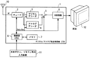
以下、本発明を具体化した一実施形態に係るデジタル/アナログ放送受信機について図面を参照して説明する。図1はデジタル/アナログ放送受信機のブロック構成を示す。受信機1は、テレビジョン放送局から発信される高周波(RF)の符号化されたデジタル/アナログ放送信号をアンテナ10により受信し、本体ボタン又は後述の図2に示したようなリモコン30等の入力装置11(入力手段)を用いたユーザからのチャンネル情報表示の操作入力に応じて、放送信号に含まれる映像信号を画面表示する表示装置12(表示手段)に受信可能なチャンネル情報を一覧表示するセットトップボックス(STB)である。
【0018】
受信機1は、所望のチャンネルに対応する周波数帯域に存在するデジタル/アナログ放送信号を受信するチューナ2(受信手段)と、チューナ2により受信したデジタル/アナログ放送信号を復号するデジタルデコーダ3、アナログデコーダ4(デジタル/アナログ復号手段)と、デジタルデコーダ3又はアナログデコーダ4によって復号された放送信号を切り換えるスイッチ5と、表示装置12に所定のオンスクリーンディスプレイ(以下、OSDと記す)表示をさせるOSD回路6(OSD出力手段)と、デジタル放送の各メインチャンネルの発信周波数やチャンネル構成情報を記憶するメモリ7と、受信機各部を制御するCPUからなる制御部8(制御手段)とを備えている。
【0019】
チューナ2は、アンテナ10により受信されたデジタル/アナログ放送信号の供給を受け、ユーザが入力装置11から制御部8に入力した指令に応じて選局動作を行ない、入力したチャンネルに対応する周波数帯域に存在するデジタル/アナログ放送信号を受信して、中間周波数(IF)に変調してデジタルデコーダ3及びアナログデコーダ4に出力する。デジタルデコーダ3及びアナログデコーダ4は、チューナ2で受信した放送信号を復号する。デジタル放送でのチャンネル構成は、各メインチャンネル毎に異なる周波数帯域が与えられており、同一メインチャンネル内のサブチャンネルは同一の周波数で放送信号が発信される。ただし、アナログ放送と同一番号を冠した仮想チャンネルを有するデジタル放送であっても、物理チャンネルが異なるので、異なる周波数帯域の搬送波によって放送信号が発信される。ユーザが選択したチャンネルがデジタル放送チャンネルであれば(サブチャンネルが“0”でない場合)、デジタルデコーダ3にて復号処理がなされる。ユーザが選択したチャンネルがアナログ放送チャンネルであれば(サブチャンネルが“0”である場合)、アナログデコーダ4にて復号処理がなされる。
【0020】
スイッチ5は、制御部8からの指令を受け、デジタルデコーダ3又はアナログデコーダ4のいずれかによって復号された放送信号をOSD回路6に出力する。OSD回路6は、制御部8からの指令により、表示装置12に放送信号を出力すると共に、受信可能なチャンネル情報に関する所定の一覧表示をさせるためのOSD表示信号を出力する。メモリ7は、各チャンネルの周波数帯域に関する情報や、チャンネル構成情報を記憶すると共に、受信機の工場出荷時にOSD表示に関する情報が記憶されている。
【0021】
制御部8は、ユーザによる入力装置11を用いた入力操作を受けて各部の制御をデータバス(Data-Bus)を通して行い、各チャンネルの周波数帯域に関する情報や受信したチャンネル情報をメモリ7に記憶させ、これらの情報をチャンネル選局時等において、必要に応じて参照する。
【0022】
また、制御部8は、ユーザからのチャンネル変更の指示により、チューナ2にチャンネル構成情報を含んだ放送信号を受信させ、この放送信号をデジタルデコーダ3によって復号処理することにより得られたチャンネル情報としてのVCTを解析してそれに含まれるステータス信号を取得する。このステータス信号には、仮想のメインチャンネル内におけるデジタル/アナログ全てのサブチャンネル情報が含まれている。従って、制御部8は、上記VCTを解析することによって、上記デジタル/アナログ放送を発信する同一又は同一系統の放送局に付与されている従前のチャンネル番号と同一の番号(メインチャンネル)とサブチャンネル番号とからなる仮想チャンネル番号を得ることができる。すなわち、同一又は同一系統の放送局から発信されるデジタル/アナログ情報を一括して取得することができる。制御部8は、取得したステータス信号をメモリ7に記憶させることで、チャンネル情報をメモリ7に記憶させる。
【0023】
さらに、制御部8は、ステータス信号に基づいて放送信号の有無を判定して、表示装置12に所定のOSD表示又は選局した放送の映像番組を映像出力させる。この表示装置12は、テレビジョン受像機の表示画面を用いてもよいし、また、CRTの他、LCD(Liquid Crystal Display)やPDP(Plasma Display Panel)等のフラットパネルディスプレイ装置であってもよい。なお、図示はしないが、受信機1は、デジタル信号をアナログ信号に変換するD/A変換回路を備えており、上記OSD表示及び映像表示のための信号はこのD/A変換回路によりアナログ信号に変換された後、表示装置12に出力される。また、上記D/A変換回路は、表示装置12に内蔵する構成としてもよい。なお、上記のフラットパネルディスプレイに表示する場合は、D/A変換回路を介さずデジタル信号のまま出力する。
【0024】
入力装置11は、ユーザによる操作指示を制御部8に対して入力するための装置である。この入力装置11の例としては、受信機1の前面に設けた本体ボタンや、図2に示したようなリモコン30が挙げられる。このリモコン30は、受信機1及びテレビジョン受像機の動作を赤外線等を用いて指示できるように構成されている。すなわち、受信機1及びテレビジョン受像機の電源をオン/オフするパワーキー31及び32と、受信機1のチャンネル番号を入力するテンキー33と、チャンネルの変更に用いるチャンネルアップ及びダウンキー34と、受信機1及びテレビジョン受像機のメニュー画面を呼び出すメニューキー35及び36と、所望の方向にカーソルを移動させる方向キー37(37a〜37d)と、入力を確定する入力(ENTER)キー38と、テレビジョン受像機の音声ボリュームを調整するボリュームアップ/ダウンキー39と、テレビジョン受像機のチャンネルの変更に用いるチャンネルアップ/ダウンキー40とを備えている。
【0025】
また、リモコン30には、上記チャンネルアップ/ダウンキー34とは別に、1つのメインチャンネル(以下メインchと記す)中でサブチャンネル(以下サブchと記す)を上下に変更するサブチャンネルアップ/ダウンキー(以下サブchキーと記す)34sが備えられている。このサブchキーは、タンブラー構成とされ、一方側を押し込むとサブchをアップし、他方を押し込むとサブchをダウンさせることができる。以下に、図3を参照して、サブchキー34sを用いたサブchを変更する動作を説明する。図3は、チャンネル情報テーブルの一例を示し、ユーザがリモコン30のメニューキー35を操作して、制御部8に指令を与えることで、メモリ7を参照して、表示装置12にEPG(Electric Program Guide)としてOSD表示される。ここでは、アナログ放送のチャンネル(以下、chと記す)“3−0”と、仮想chが付与されたデジタル放送のch“1−2”,“2−1”…“2−4”,“3−1”,“4−1”が表示されている。ここで、ch“2−0”及び“4−0”がチャンネル情報テーブルに存在しないのは、これらの放送が停止され、メモリ7にチャンネル情報が記憶されていないからである。チャンネル情報テーブルは、上下(縦)方向に各メインchにおけるアナログ放送のチャンネルとデジタル放送の仮想ch(小さい数から順に)とが上から順に並ぶ。このチャンネル情報テーブルにおいて、白黒反転表示されるch“2−1”〜“2−4”は、現在受信中のメインchを示し、その中でも、さらに白黒反転表示されるch“2−2”は、現在受信中の仮想chを示している。
【0026】
このOSD表示画面から、サブchキー34sのアップ側が押されると、同一メインch“2”内で、上方向に隣接するサブchを検索し、ch“2−1”に変更される。さらに、サブchキー34sのアップ側が押されると、同メインch内には、上方向に隣接するサブchは存在しないので、同メインch内で最大のサブch番号が付与されたch“2−4”に変更される。チャンネル情報テーブルの右横の矢印は、このようにサブchキー34sが操作される毎に、同一メインch内で、順次、切り替えられるチャンネルの選択順を示している。なお、サブchキー34sが押された場合も、変更するチャンネルを検索する方向が逆になるだけで同様の切り替えが成される。ch“2−4”を受信中に、サブchキー34sのダウン側が押されると、同メインch内には、下方向に隣接するサブchは存在しないので、同メインch内で最小のサブch番号が付与されたch“2−1”に変更される。
【0027】
次に、ユーザのリモコン30のサブchキー34sの操作による、チャンネル変更の指示が入力されたときの受信機1の制御部8による動作処理について図4を参照して説明する。まず、ユーザからのサブchキー34sの入力を受け(#1)、その入力がアップ側であれば(#2においてアップ)、メモリ7に記憶したチャンネル情報を参照して(#3)、同一メインch内に上方向に隣接するサブchが存在するかを検索する(#4)。隣接するサブchが存在すれば(#4においてYES)、該当するサブchを選択する(#5)。隣接するサブchが存在しなければ(#4においてNO)、同一メインch内で最大番号のサブchを選択する(#6)。
【0028】
また、サブchキー34sの入力がダウン側キー34bであれば(#2においてダウン)、メモリ7に記憶したチャンネル情報を参照して(#7)、同一メインch内に下方向に隣接するサブchが存在するかを検索する(#8)。隣接するサブchが存在すれば(#8においてYES)、該当するサブchを選択する(#9)。隣接するサブchが存在しなければ(#8においてNO)、同一メインch内で最小番号のサブchを選択する(#10)。このようにして、ユーザのサブchキー34sの入力を受ける毎に、同一メインch内でサブchを循環(回転)させながら選択することができる。
【0029】
なお、本発明は上記実施形態の構成に限られることなく種々の変形が可能であり、例えば、上記では、サブchキー34sをサブchのアップ/ダウン専用キーとして別個に設けた例を示したが、モードを切り替えることでチャンネルアップ/ダウンキー34にサブchキーの機能を持たせたものでもよい。
【0030】
また、図5に示した#6/#10におけるサブchの選択は、最大/最小のサブchに限られることなく、キー入力に対して反対方向に隣接するサブchを選択することとしてもよい。この場合は、同一メインch内でサブchを折返し往復させながら、選択されることとなる。さらに、このサブchの選択は、デジタルの内、最小番号のサブch“1”が選択されるものとしてもよい。このサブch“1”は、ATSCでは通常、サブch“0”のアナログ放送と同じ内容のデジタル放送が発信される運用が成されており、最も視聴要求が高いと考えられる。従って、この例では、最も視聴要求が高いサブchが優先的に選択されることとなる。
【0031】
さらに、図3に示したチャンネル情報テーブルは、リモコン30のサブchキー34sを操作して、制御部8にチャンネルを変更する指令を与えたときに表示装置12にOSD表示するものとしてもよい。さらに、この場合において、サブch変更指令を受けたときに、チャンネル情報テーブルをOSD表示することなく、受信した映像を直ちに表示装置12に出力することとしてもよい。さらにまた、受信機1をテレビジョン受像機やビデオ記録装置の本体に内蔵した構成としてもよい。
【0032】
【発明の効果】
以上のように請求項1の発明によれば、同一メインチャンネル内で、サブチャンネルのみを変更することができるから、メインチャンネルの変更に伴う選局動作の遅延を招くことがなく、素早く選局することができる。また、ユーザによる操作キーの操作毎に、ユーザが指示した方向にサブチャンネルを循環させながら、順次選局していくので、ユーザは直感的に操作しやすく、操作性が向上する。さらに、ユーザのお気に入りのメインチャンネルがあり、そのメインチャンネル内でサブチャンネルのみを変更したいときにも快適にチャンネル選択することができる。
【0033】
請求項2の発明によれば、同一メインチャンネル内で、サブチャンネルのみを変更することができるから、メインチャンネルの変更に伴う選局動作の遅延を招くことがなく、素早く選局することができる。さらに、ユーザのお気に入りのメインチャンネルがあり、そのメインチャンネル内でサブチャンネルのみを変更したいときにも快適にチャンネル選択をすることができる。
【0034】
請求項3の発明によれば、ユーザは表示手段に表示されたチャンネル情報の一覧を確認しながら、入力手段の操作キーの操作指示を与え、カーソル位置のサブチャンネルを選択することができ、使い勝手の向上を図ることができる。
【0035】
請求項4の発明によれば、ATSC規格のデジタル放送、及び、NTSC規格のアナログ放送の受像機において、チャンネルアップ/ダウン選択が容易に行える。
【図面の簡単な説明】
【図1】 本発明の一実施形態による放送受信機のブロック構成図。
【図2】 同装置に用いられるリモコンの平面図。
【図3】 同装置によるチャンネル情報テーブルの表示画面と、チャンネルアップキーが押されたときのチャンネルの選択順を示す図。
【図4】 同装置の制御部による動作のフローチャート。
【図5】 同装置により受信されるデジタル放送のチャンネル構成を示した図。
【符号の説明】
1 放送受信機
2 チューナ(受信手段)
3 デジタルデコーダ(デジタル復号手段)
4 アナログデコーダ(アナログ復号手段)
6 OSD回路(OSD出力手段)
8 制御部(制御手段、データ追加手段、データ削除手段)
11 入力装置(入力手段)
12 表示装置(表示手段)
34s サブchキー(上/下キー)[0001]
BACKGROUND OF THE INVENTION
The present invention relates to a channel selection device for a digital / analog broadcast receiver and a digital / analog broadcast receiver including the same.
[0002]
[Prior art]
Conventionally, in a digital / analog broadcast receiver, a user selects a channel using an input means, and the digital / analog is based on a channel number inputted numerically or based on an operation of a channel up / down key. While referring to the digital / analog channel table showing the broadcast viewable channels, it is determined whether the selected channel is a digital / analog broadcast channel, and the tuner receives the broadcast signal of the corresponding channel. There is a channel selection device of a digital / analog broadcast receiving device having a function (for example, see Japanese Patent Application Laid-Open No. 11-164214).
[0003]
By the way, television broadcasting is generally analog broadcasting, but in recent years, it has become BS (Broadcasting Satellite) digital broadcasting and CS (Communications Satellite) digital broadcasting that can achieve higher image quality and multi-channels. Represented digital broadcasts are being transmitted and are rapidly spreading. For example, digital broadcasting in North America is standardized by ATSC (Advanced Television Systems Committee), and is transmitted through physical channels different from analog broadcasting. Among these, there are many digital broadcasts transmitted from the same or the same system as the conventional analog broadcast. In this case, in order to improve the usability of users who are used to the channel number of the conventional analog broadcast, It is operated so that channel selection and display can be performed by a virtual channel assigned with the same channel number as that of analog broadcasting.
[0004]
In digital broadcasting, carriers of a predetermined frequency band different from analog broadcasting are assigned to each channel. This channel is called a main channel, and one main channel includes subchannels for transmitting one or a plurality of contents. The configuration of the subchannel varies depending on the broadcast time zone. As an example, the configuration of the subchannel in a certain time zone (PM8: 0 to PM12: 00) of the main channel “4” is shown in FIG.
[0005]
According to FIG. 5, the subchannels “0” to “4” are in PM8: 0 to PM9: 00, and the subchannels “0” and “1” are in PM10: 00 to PM10: 00. From 00 to PM11: 00, subchannels “0” to “4” are broadcast, and from PM11: 00 to PM12: 00, subchannels “0” to “3” are broadcast. Here, a channel whose subchannel is “0” (physical channel is “4-0”) is analog broadcasting according to the NTSC (National Television Systems Committee) standard, and the subchannel is “1” to “4” (virtual channels are Channels “4-1” to “4-4”) are digital broadcasts. The TV program broadcast from channel “4-0” is a conventional analog broadcast television program, and the SD (Standard Definition) program broadcast from channels “4-1” to “4-4” An HD (High Definition) program, which is a standard quality program for digital broadcasting and broadcast from channel “4-1”, is a high quality program for digital broadcasting.
[0006]
In digital broadcasting, information about the channel configuration that varies as described above (hereinafter referred to as channel information) is transmitted together with a signal such as video. Therefore, in the digital broadcast receiving apparatus, if the digital broadcast signal is received by the tuner, decoded by the digital decoder, and the VCT (Virtual Channel Table) included in the decoded signal is analyzed, the channel information of the broadcast is acquired. Can do.
[0007]
[Problems to be solved by the invention]
In a channel selection device of a conventional digital / analog broadcast receiver, VCT including virtual channel information based on PSIP (Program System Information Protocol) is obtained by decoding and analyzing a broadcast signal, and this is obtained. Stores the memorized channel map, and when the user changes or selects a channel, the channel selection screen is displayed by an EPG (Electric Program Guide) functioning as an interface based on this channel map, and the operation unit of the main body or the remote There are some which can change / select a channel by operating a key (for example, an up key / down key) of a control device. According to this, it is not necessary to input a troublesome channel number, but the main channel is changed when there is no subchannel adjacent in the key input direction in the same main channel.
[0008]
For example, in PM11: 0 to PM12: 00 shown in FIG. 5, when the user inputs the down key while receiving the channel “4-3” and considering that the channel “4-4” exists, The main channel is also changed (adjacent main channel, for example, channel “5”). The main channel is changed by changing the reception frequency of the tuner, acquiring the VCT including the subchannel information in the adjacent main channel, and extracting the broadcast signal of any subchannel based on this information. Made. Among these, in particular, the VCT is mixed with the broadcast signal and transmitted every predetermined time. Therefore, it takes a certain time to change the main channel through the above steps. Therefore, when the main channel is changed by the channel up / down key as described above, the time required for channel selection becomes long, which is inconvenient. In addition, there is a case where the user has a favorite main channel (broadcast station) and wants to change only the sub-channel in the main channel. In such a case, the user can operate the channel up / down key to operate the user. Contrary to the intention, the main channel may be changed, and the operability is not good.
[0009]
The present invention has been made in order to solve the above-described problems, and corresponds to digital broadcasting having a hierarchical and frequently changing channel configuration including main / sub-channels, and only the sub-channels are changed. An object of the present invention is to provide a channel selection device for a digital / analog broadcast receiver that includes a key for controlling the channel and prevents a delay in the time required for channel change while improving user convenience.
[0010]
[Means for Solving the Problems]
In order to achieve the above object, the invention of
[0011]
In this configuration, the digital broadcast signal includes subchannels that transmit one or a plurality of contents per main channel, and virtual channels including the same numbers as the analog broadcast channel numbers are allocated to these subchannels. Therefore, users who are familiar with analog broadcasting can tune in without feeling uncomfortable. Then, the user gives an instruction to select the subchannel adjacent to the up / down by operating the up / down key provided in the input means. The control means receives an instruction from the up / down key, and changes the subchannel in either of the up / down directions based on the channel information stored in the storage means.
[0012]
Even if there is no subchannel in the designated direction in the same main channel, the main channel is not changed, but is changed to a subchannel with the number farthest from the subchannel before the operation. That is, when the user operates the up key and there is no subchannel in the upward direction (the direction in which the subchannel number decreases) , the adjacent subchannel is selected in the direction in which the subchannel number increases . In addition, when the user operates the down key and there is no subchannel in the downward direction (the direction in which the subchannel number increases) , the adjacent subchannel is selected in the direction in which the subchannel number decreases . In this way, when the operation key is repeatedly operated by the user, the subchannel is changed while turning back and forth in the same main channel, and the main channel is not changed even if the operation key is operated in a direction in which no subchannel exists. Therefore, the time required for channel change is not delayed.
[0017]
DETAILED DESCRIPTION OF THE INVENTION
Hereinafter, a digital / analog broadcast receiver according to an embodiment of the present invention will be described with reference to the drawings. FIG. 1 shows a block configuration of a digital / analog broadcast receiver. The
[0018]
The
[0019]
The
[0020]
The
[0021]
The
[0022]
Further, the
[0023]
Further, the
[0024]
The
[0025]
In addition to the channel up / down key 34, the
[0026]
When the up side of the sub ch key 34 s is pressed from this OSD display screen, the sub ch adjacent in the upward direction is searched in the same main ch “2” and changed to ch “2-1”. Further, when the up side of the sub ch key 34s is pressed, there is no sub ch adjacent in the upward direction in the main ch, and therefore the ch “2-” assigned the largest sub ch number in the main ch. It is changed to 4 ″. The arrow on the right side of the channel information table indicates the selection order of channels that are sequentially switched in the same main channel every time the sub channel key 34s is operated in this way. Even when the sub ch key 34s is pressed, the same switching is performed only by reversing the direction of searching for the channel to be changed. When the down side of the sub ch key 34s is pressed while receiving the channel “2-4”, there is no sub channel adjacent in the downward direction in the main channel, so the smallest sub channel in the main channel is present. It is changed to ch “2-1” to which the number is assigned.
[0027]
Next, an operation process performed by the
[0028]
If the input of the sub ch key 34s is the down side key 34b (down in # 2), the channel information stored in the
[0029]
The present invention is not limited to the configuration of the above-described embodiment, and various modifications are possible. For example, in the above, an example in which the sub ch key 34s is separately provided as a sub ch up / down dedicated key is shown. However, the channel up / down key 34 may have the function of the sub ch key by switching the mode.
[0030]
Further, the selection of the subch in # 6 / # 10 shown in FIG. 5 is not limited to the maximum / minimum subch, and may be a subch adjacent to the key input in the opposite direction. . In this case, selection is performed while the sub ch is turned back and forth within the same main ch. Further, the sub-ch may be selected by selecting the sub-ch “1” having the smallest number in the digital. This sub-ch “1” is normally operated so that a digital broadcast having the same content as the analog broadcast of the sub-ch “0” is transmitted in the ATSC, and is considered to have the highest viewing request. Therefore, in this example, the subch with the highest viewing request is preferentially selected.
[0031]
Further, the channel information table shown in FIG. 3 may be OSD-displayed on the
[0032]
【The invention's effect】
As described above, according to the first aspect of the present invention, since only the sub-channel can be changed within the same main channel, the channel selection operation is not delayed due to the change of the main channel, and the channel can be selected quickly. can do. Further, every time the user operates the operation key, the channel is sequentially selected while circulating the subchannel in the direction instructed by the user, so that the user can easily operate intuitively and the operability is improved. Furthermore, when there is a user's favorite main channel and it is desired to change only the sub-channel within the main channel, the channel can be selected comfortably.
[0033]
According to the invention of
[0034]
According to the third aspect of the invention, the user can select the sub-channel at the cursor position by giving the operation instruction of the operation key of the input means while checking the list of the channel information displayed on the display means. Can be improved.
[0035]
According to the fourth aspect of the present invention, channel up / down selection can be easily performed in receivers for ATSC standard digital broadcasting and NTSC standard analog broadcasting.
[Brief description of the drawings]
FIG. 1 is a block diagram of a broadcast receiver according to an embodiment of the present invention.
FIG. 2 is a plan view of a remote controller used in the apparatus.
FIG. 3 is a diagram showing a display screen of a channel information table by the apparatus and a channel selection order when a channel up key is pressed.
FIG. 4 is a flowchart of an operation performed by a control unit of the apparatus.
FIG. 5 is a diagram showing a channel configuration of digital broadcasting received by the apparatus.
[Explanation of symbols]
1
3 Digital decoder (digital decoding means)
4 Analog decoder (analog decoding means)
6 OSD circuit (OSD output means)
8 Control unit (control means, data addition means, data deletion means)
11 Input device (input means)
12 Display device (display means)
34s Subch key (Up / Down key)
Claims (1)
前記制御手段は、前記入力手段からチャンネル選択の指示を受けたとき、選択されたチャンネルについて前記受信手段に放送信号を受信させ、この受信させた放送信号を前記デジタル復号手段によって復号させ、この復号させた放送信号に含まれるチャンネル情報を取得し、前記記憶手段に記憶させる機能を有したデジタル/アナログ放送受信機のチャンネル選択装置において、
デジタル放送とアナログ放送とは互いに異なるチャンネルにより発信され、デジタル放送は、1つのメインチャンネルに1又は複数のコンテンツを発信するためのサブチャンネルを含み、かつ、これらのサブチャンネルにアナログ放送のメインチャンネルと同じ番号を冠した仮想チャンネルが付与されており、
前記入力手段は、同一のメインチャンネル内で上/下に隣接するサブチャンネルを選択する指示を前記制御手段に与えるための上/下キーを有し、
前記制御手段は、前記上キーが操作される毎に、前記記憶手段に記憶させたチャンネル情報を参照して、現在受信中のメインチャンネル内でサブチャンネルの番号が小さくなる方向に隣接するサブチャンネルを選局するものとし、前記下キーが操作される毎に、前記記憶手段に記憶させたチャンネル情報を参照して、現在受信中のメインチャンネル内でサブチャンネルの番号が大きくなる方向に隣接するサブチャンネルを選局するものとし、
前記上キーによる指示が与えられた場合において、前記チャンネル情報に該メインチャンネル内に、サブチャンネルの番号が小さくなる方向に隣接するチャンネルがないときは、サブチャンネルの番号が大きくなる方向に隣接するサブチャンネルを選局し、前記下キーによる指示が与えられた場合において、前記チャンネル情報に該メインチャンネル内に、サブチャンネルの番号が大きくなる方向に隣接するチャンネルがないときは、サブチャンネルの番号が小さくなる方向に隣接するサブチャンネルを選局することを特徴とするデジタル/アナログ放送受信機のチャンネル選択装置。Receiving means for receiving an encoded digital / analog broadcast signal transmitted from a broadcasting station, and digital / analog decoding for decoding the digital / analog broadcast signal received by the receiving means and outputting it to a display means for displaying video Means, storage means for storing channel information included in the broadcast signal decoded by the digital decoding means, control means for controlling each part of the receiver, and a user inputs a channel selection instruction to the control means Input means for,
The control means, when receiving a channel selection instruction from the input means, causes the receiving means to receive a broadcast signal for the selected channel, and causes the digital decoding means to decode the received broadcast signal. In the channel selection device of a digital / analog broadcast receiver having a function of acquiring channel information included in the broadcast signal and storing it in the storage means,
Digital broadcasting and analog broadcasting are transmitted by different channels, and digital broadcasting includes subchannels for transmitting one or a plurality of contents in one main channel, and the analog broadcasting main channel is included in these subchannels. A virtual channel with the same number as
The input means has an up / down key for giving an instruction to the control means to select a subchannel adjacent up / down within the same main channel;
Wherein, each time said Ueki over is operated, the sub which refers to the channel information stored in the storage means, adjacent to the direction in which the sub-channel number is reduced in the main channel of the currently received Each time the down key is operated, the channel is selected, and the channel information stored in the storage means is referred to and the subchannel number is adjacent in the direction in which the subchannel number is increased. Select the subchannel to be
When the channel key information is given and there is no adjacent channel in the main channel in the direction of decreasing the subchannel number , the channel information is adjacent in the direction of increasing the subchannel number. When a subchannel is selected and an instruction by the down key is given, if there is no channel adjacent to the channel information in the direction in which the subchannel number increases , the subchannel number A channel selection device for a digital / analog broadcast receiver, wherein a channel is selected from adjacent subchannels in a direction in which the signal becomes smaller .
Priority Applications (2)
| Application Number | Priority Date | Filing Date | Title |
|---|---|---|---|
| JP2001024504A JP4552333B2 (en) | 2001-01-31 | 2001-01-31 | Channel selector for digital / analog broadcast receiver and digital / analog broadcast receiver equipped with the same |
| US10/058,035 US7281259B2 (en) | 2001-01-31 | 2002-01-29 | Channel selection device for use in a digital/analog broadcasting receiver for reception of main and sub channels |
Applications Claiming Priority (1)
| Application Number | Priority Date | Filing Date | Title |
|---|---|---|---|
| JP2001024504A JP4552333B2 (en) | 2001-01-31 | 2001-01-31 | Channel selector for digital / analog broadcast receiver and digital / analog broadcast receiver equipped with the same |
Publications (2)
| Publication Number | Publication Date |
|---|---|
| JP2002232794A JP2002232794A (en) | 2002-08-16 |
| JP4552333B2 true JP4552333B2 (en) | 2010-09-29 |
Family
ID=18889635
Family Applications (1)
| Application Number | Title | Priority Date | Filing Date |
|---|---|---|---|
| JP2001024504A Expired - Fee Related JP4552333B2 (en) | 2001-01-31 | 2001-01-31 | Channel selector for digital / analog broadcast receiver and digital / analog broadcast receiver equipped with the same |
Country Status (2)
| Country | Link |
|---|---|
| US (1) | US7281259B2 (en) |
| JP (1) | JP4552333B2 (en) |
Families Citing this family (37)
| Publication number | Priority date | Publication date | Assignee | Title |
|---|---|---|---|---|
| JP2002223396A (en) * | 2001-01-25 | 2002-08-09 | Funai Electric Co Ltd | Channel selecting device for digital/analog broadcast receiver |
| JP2002232793A (en) * | 2001-01-31 | 2002-08-16 | Funai Electric Co Ltd | Channel tuning apparatus of digital/analog broadcasting receiver and the receiver with the apparatus |
| JP2002232796A (en) * | 2001-01-31 | 2002-08-16 | Funai Electric Co Ltd | Channel tuning apparatus of digital/analog broadcasting receiver |
| JP2002232795A (en) * | 2001-01-31 | 2002-08-16 | Funai Electric Co Ltd | Channel tuning apparatus of digital/analog broadcasting receiver and the receiver with the apparatus |
| KR100467585B1 (en) * | 2002-05-29 | 2005-01-24 | 삼성전자주식회사 | Method for setting highlight window using remote controller and apparatus thereof |
| JP3733093B2 (en) * | 2002-08-22 | 2006-01-11 | 三洋電機株式会社 | Broadcast receiving apparatus and broadcast receiving method |
| US7456907B2 (en) * | 2004-01-23 | 2008-11-25 | Thomson Licensing | Method and apparatus for sharing control signals in a television apparatus supporting multi-window capabilities |
| JP2005277997A (en) * | 2004-03-26 | 2005-10-06 | Clarion Co Ltd | Digital broadcasting receiver |
| US7956935B2 (en) * | 2005-04-13 | 2011-06-07 | Toshiba America Information Systems, Inc. | Control method and device for controlling a controllable device |
| JP2006352752A (en) * | 2005-06-20 | 2006-12-28 | Funai Electric Co Ltd | Broadcast image receiver, broadcast receiver, channel addition control method, and channel deletion control method |
| KR100716172B1 (en) * | 2005-07-12 | 2007-05-10 | 삼성전자주식회사 | Apparatus and Method for Changing the Channel in Digital Broadcasting System |
| KR100721387B1 (en) | 2005-10-07 | 2007-05-28 | 삼성전자주식회사 | Remote controller and image system comprising the same |
| KR100730718B1 (en) | 2005-10-11 | 2007-06-21 | 삼성전자주식회사 | Video processing apparatus and video processing method |
| KR100686152B1 (en) * | 2005-10-26 | 2007-02-26 | 엘지전자 주식회사 | Method of changing/managing channel and broadcastingg receiver thereof |
| JP4788402B2 (en) * | 2006-03-02 | 2011-10-05 | 船井電機株式会社 | Digital broadcast receiver |
| TWI315157B (en) * | 2006-04-06 | 2009-09-21 | Au Optronics Corporatio | Method, system and storage medium for changing channel |
| US8356330B2 (en) * | 2006-06-05 | 2013-01-15 | Shenzhen Tcl New Technology Ltd | Channel entry system and method |
| EP1879376A3 (en) | 2006-06-13 | 2011-04-06 | Samsung Electronics Co., Ltd. | Fast channel switching method and apparatus for digital broadcast receiver |
| KR101271665B1 (en) * | 2006-09-22 | 2013-06-05 | 삼성전자주식회사 | Method for shifting channel and image display apparatus thereof |
| KR100818247B1 (en) * | 2006-10-18 | 2008-04-01 | 삼성전자주식회사 | Digital broadcast receiving device and channel selection method |
| KR100844146B1 (en) | 2006-10-20 | 2008-07-04 | 삼성전자주식회사 | Method for tuning according to variable key input length and broadcast receiving apparatus thereof |
| WO2008051209A1 (en) * | 2006-10-23 | 2008-05-02 | Tte Technology, Inc. | System and method for accommodation of digital and analog channel number conflicts |
| US20080101415A1 (en) * | 2006-10-25 | 2008-05-01 | Microsoft Corporation | Private data transmission via an analog broadcast transmission |
| KR20080046063A (en) * | 2006-11-21 | 2008-05-26 | 삼성전자주식회사 | Broadcasting signal receiving apparatus and control method thereof |
| JP2008263534A (en) * | 2007-04-13 | 2008-10-30 | Funai Electric Co Ltd | Digital broadcast receiver |
| US9628761B2 (en) * | 2007-07-26 | 2017-04-18 | The Directv Group, Inc. | Method for arranging virtual channels and linear channels for a content processing system |
| KR101427111B1 (en) * | 2007-08-01 | 2014-08-07 | 삼성전자 주식회사 | Image processing apparatus and control method thereof |
| JP2008206200A (en) * | 2008-05-12 | 2008-09-04 | Toshiba Corp | Broadcast receiving device and broadcast receiving method |
| JP2008236788A (en) * | 2008-05-12 | 2008-10-02 | Toshiba Corp | Broadcast receiver and broadcast reception method |
| JP2008206201A (en) * | 2008-05-12 | 2008-09-04 | Toshiba Corp | Broadcast receiving device and broadcast receiving method |
| JP2008193749A (en) * | 2008-05-12 | 2008-08-21 | Toshiba Corp | Broadcast receiver, and broadcast reception method |
| JP2008228339A (en) * | 2008-05-12 | 2008-09-25 | Toshiba Corp | Broadcast receiver and broadcast reception method |
| JP2008252922A (en) * | 2008-05-12 | 2008-10-16 | Toshiba Corp | Broadcast receiver and broadcast reception method |
| JP2008193748A (en) * | 2008-05-12 | 2008-08-21 | Toshiba Corp | Broadcast receiver, and broadcast reception method |
| JP2008211841A (en) * | 2008-05-12 | 2008-09-11 | Toshiba Corp | Broadcast receiver and broadcast reception method |
| US8285900B2 (en) * | 2009-02-17 | 2012-10-09 | The Board Of Regents Of The University Of Texas System | Method and apparatus for congestion-aware routing in a computer interconnection network |
| FR3007615A1 (en) | 2013-06-24 | 2014-12-26 | France Telecom | METHOD FOR IMPROVING THE CHANGE TIME BETWEEN AUDIOVISUAL PROGRAMS |
Citations (3)
| Publication number | Priority date | Publication date | Assignee | Title |
|---|---|---|---|---|
| JPH11341383A (en) * | 1998-05-22 | 1999-12-10 | Sanyo Electric Co Ltd | Television receiver |
| WO2000078039A1 (en) * | 1999-06-16 | 2000-12-21 | Thomson Licensing S.A. | Real-time signal strength display of terrestrial digital television signals |
| JP2001008117A (en) * | 1999-06-23 | 2001-01-12 | Victor Co Of Japan Ltd | Digital proadcast receiver |
Family Cites Families (44)
| Publication number | Priority date | Publication date | Assignee | Title |
|---|---|---|---|---|
| JPS552760A (en) | 1978-06-23 | 1980-01-10 | High Frequency Heattreat Co Ltd | High strength, cold plastic-shaped steel of very high durability and creep resistance, and manufacture thereof |
| US5020139A (en) | 1990-03-05 | 1991-05-28 | Rca Licensing Corporation | Three digit channel entry by use of an extended keypress |
| US5410326A (en) | 1992-12-04 | 1995-04-25 | Goldstein; Steven W. | Programmable remote control device for interacting with a plurality of remotely controlled devices |
| US5461427A (en) | 1994-06-28 | 1995-10-24 | Thomson Consumer Electronics, Inc. | Television receiver having the capability to associate any HDTV and any NTSC channel |
| US6215530B1 (en) | 1995-05-22 | 2001-04-10 | Scientific-Atlanta, Inc. | Logical and composite channel mapping in an MPEG network |
| US6075575A (en) * | 1995-10-02 | 2000-06-13 | Starsight Telecast, Inc. | Remote control device and method for using television schedule information |
| JPH1042212A (en) | 1996-07-24 | 1998-02-13 | Sony Corp | Device and method for reception |
| US5982411A (en) * | 1996-12-18 | 1999-11-09 | General Instrument Corporation | Navigation among grouped television channels |
| JP3814903B2 (en) | 1996-12-25 | 2006-08-30 | 株式会社日立製作所 | Video / data display method and apparatus |
| US5850218A (en) * | 1997-02-19 | 1998-12-15 | Time Warner Entertainment Company L.P. | Inter-active program guide with default selection control |
| KR100217184B1 (en) | 1997-06-30 | 1999-09-01 | 윤종용 | Channel switching method of multi channel tv receiver |
| KR100317629B1 (en) | 1997-06-30 | 2002-04-24 | 윤종용 | How to Display Subchannel Information on a Digital Television Receiver |
| US6111611A (en) * | 1997-07-10 | 2000-08-29 | Thomson Consumer Electronics | System for forming and processing program specific information suitable for terrestrial, cable or satellite broadcast |
| US6836296B1 (en) | 1997-07-18 | 2004-12-28 | Sony Corporation | Control device, control method, electric apparatus, control method of an electric apparatus, electric apparatus system, control method of an electric apparatus system, and transmission medium |
| JPH11164214A (en) | 1997-11-27 | 1999-06-18 | Sanyo Electric Co Ltd | Television broadcasting receiver |
| US6564378B1 (en) | 1997-12-08 | 2003-05-13 | United Video Properties, Inc. | Program guide system with browsing display |
| US6367078B1 (en) * | 1997-12-12 | 2002-04-02 | Michael Lasky | Electronic program-guide system with sideways-surfing capability |
| JPH11261906A (en) | 1998-01-12 | 1999-09-24 | Sony Corp | Television broadcast receiver, television broadcast reception method and television broadcast method |
| JP4078717B2 (en) | 1998-01-21 | 2008-04-23 | ソニー株式会社 | Program tuning method and receiving apparatus |
| US6483547B1 (en) * | 1998-03-03 | 2002-11-19 | General Instrument Corporation | Transmission signal ID for analog television broadcasts |
| US6754905B2 (en) | 1998-07-23 | 2004-06-22 | Diva Systems Corporation | Data structure and methods for providing an interactive program guide |
| KR100330012B1 (en) * | 1998-09-14 | 2002-08-08 | 삼성전자 주식회사 | How to change channels on television |
| US6661472B2 (en) * | 1998-09-30 | 2003-12-09 | Sony Corporation | Channel selection in digital television |
| US6313886B1 (en) * | 1998-10-14 | 2001-11-06 | Sony Corporation | Automatic PSIP detection system and method |
| US7412715B2 (en) * | 1998-10-28 | 2008-08-12 | Samsung Electronics Co., Ltd. | Method and apparatus for displaying channel information and selecting channel on digital television |
| JP3490619B2 (en) | 1998-11-24 | 2004-01-26 | 株式会社東芝 | Digital broadcast receiver |
| US6766526B1 (en) | 1998-12-03 | 2004-07-20 | United Video Properties, Inc. | Smart channel entry system |
| US6396523B1 (en) | 1999-07-29 | 2002-05-28 | Interlink Electronics, Inc. | Home entertainment device remote control |
| KR100311479B1 (en) | 1999-10-06 | 2001-10-18 | 구자홍 | Method and apparatus for controlling channel of digital TV |
| KR100348249B1 (en) | 1999-10-08 | 2002-08-09 | 엘지전자 주식회사 | Data architecture of VCT and method for transmit/receiving service information |
| US6775843B1 (en) | 1999-10-14 | 2004-08-10 | Sony Corporation | Method and apparatus for digital TV channel mapping |
| US6825874B1 (en) | 1999-12-14 | 2004-11-30 | Intel Corporation | Monitoring the degree of action in video transmissions |
| KR100317389B1 (en) | 2000-01-22 | 2001-12-22 | 구자홍 | Channel setting method for the on timer of digital broadcasting tv receiver |
| US6817027B1 (en) | 2000-03-31 | 2004-11-09 | Matsushita Electric Industrial Co., Ltd. | Display interface comprising a channel matrix |
| US6621528B1 (en) * | 2000-05-22 | 2003-09-16 | Sony Corporation | Channel control for digital television |
| US6714264B1 (en) * | 2000-08-31 | 2004-03-30 | Matsushita Electric Industrial Co., Ltd. | Digital television channel surfing system |
| JP4626737B2 (en) | 2000-12-05 | 2011-02-09 | 船井電機株式会社 | Digital / analog television signal receiver |
| US6387078B1 (en) | 2000-12-21 | 2002-05-14 | Gillespie, Iii Richard D. | Automatic mixing and injecting apparatus |
| JP2002223396A (en) * | 2001-01-25 | 2002-08-09 | Funai Electric Co Ltd | Channel selecting device for digital/analog broadcast receiver |
| JP2002232793A (en) | 2001-01-31 | 2002-08-16 | Funai Electric Co Ltd | Channel tuning apparatus of digital/analog broadcasting receiver and the receiver with the apparatus |
| JP2002232795A (en) | 2001-01-31 | 2002-08-16 | Funai Electric Co Ltd | Channel tuning apparatus of digital/analog broadcasting receiver and the receiver with the apparatus |
| JP2002232796A (en) | 2001-01-31 | 2002-08-16 | Funai Electric Co Ltd | Channel tuning apparatus of digital/analog broadcasting receiver |
| JP2002246881A (en) | 2001-02-16 | 2002-08-30 | Funai Electric Co Ltd | Channel selecting device for broadcasting receiver and broadcasting receiver having the same device |
| JP3632205B2 (en) | 2001-05-15 | 2005-03-23 | 船井電機株式会社 | Receiver |
-
2001
- 2001-01-31 JP JP2001024504A patent/JP4552333B2/en not_active Expired - Fee Related
-
2002
- 2002-01-29 US US10/058,035 patent/US7281259B2/en not_active Expired - Fee Related
Patent Citations (4)
| Publication number | Priority date | Publication date | Assignee | Title |
|---|---|---|---|---|
| JPH11341383A (en) * | 1998-05-22 | 1999-12-10 | Sanyo Electric Co Ltd | Television receiver |
| WO2000078039A1 (en) * | 1999-06-16 | 2000-12-21 | Thomson Licensing S.A. | Real-time signal strength display of terrestrial digital television signals |
| JP2003502919A (en) * | 1999-06-16 | 2003-01-21 | トムソン ライセンシング ソシエテ アノニム | Real-time signal strength display of terrestrial digital television signals |
| JP2001008117A (en) * | 1999-06-23 | 2001-01-12 | Victor Co Of Japan Ltd | Digital proadcast receiver |
Also Published As
| Publication number | Publication date |
|---|---|
| US7281259B2 (en) | 2007-10-09 |
| US20020104102A1 (en) | 2002-08-01 |
| JP2002232794A (en) | 2002-08-16 |
Similar Documents
| Publication | Publication Date | Title |
|---|---|---|
| JP4552333B2 (en) | Channel selector for digital / analog broadcast receiver and digital / analog broadcast receiver equipped with the same | |
| JP4543557B2 (en) | Broadcast receiving apparatus having on-screen display function of channel information | |
| US7050117B2 (en) | Channel selection device used in digital/analog broadcasting receiver | |
| US7030933B2 (en) | Broadcast receiving system with function of on-screen displaying channel information | |
| US20100002141A1 (en) | Method and apparatus for displaying channel information and selecting channel on digital television | |
| JP4581264B2 (en) | Digital / analog broadcast receiver | |
| KR100317629B1 (en) | How to Display Subchannel Information on a Digital Television Receiver | |
| US20060037045A1 (en) | System and method for previewing and switching to favorite channels | |
| JP2002246881A (en) | Channel selecting device for broadcasting receiver and broadcasting receiver having the same device | |
| JP2002232793A (en) | Channel tuning apparatus of digital/analog broadcasting receiver and the receiver with the apparatus | |
| JP2002232795A (en) | Channel tuning apparatus of digital/analog broadcasting receiver and the receiver with the apparatus | |
| US20020104103A1 (en) | Channel selection device for digital/analog broadcasting receiver | |
| US8502923B2 (en) | Method for switching a channel of an image display device and apparatus therefor | |
| US7456907B2 (en) | Method and apparatus for sharing control signals in a television apparatus supporting multi-window capabilities | |
| JP4752330B2 (en) | Broadcast receiver and channel selector for broadcast receiver | |
| EP1709797B1 (en) | Method and apparatus for sharing control signals in a television apparatus supporting multi-window capabilities | |
| KR100279119B1 (en) | Method for selecting channel in digital television receiver and device thereof | |
| JP2003189199A (en) | Channel selector for digital broadcast receiver | |
| KR20090074908A (en) | Digital broadcasting receiver and method for channel conversion of digital broadcasting receiver | |
| KR100720704B1 (en) | Broadcasting receiver for displaying analog and digital broadcast images and method thereof | |
| MXPA06008301A (en) | Method and apparatus for sharing control signals in a television apparatus supporting multi-window capabilities | |
| JP2002033970A (en) | Station-selecting device |
Legal Events
| Date | Code | Title | Description |
|---|---|---|---|
| A621 | Written request for application examination |
Free format text: JAPANESE INTERMEDIATE CODE: A621 Effective date: 20071213 |
|
| A131 | Notification of reasons for refusal |
Free format text: JAPANESE INTERMEDIATE CODE: A131 Effective date: 20100302 |
|
| A521 | Request for written amendment filed |
Free format text: JAPANESE INTERMEDIATE CODE: A523 Effective date: 20100428 |
|
| TRDD | Decision of grant or rejection written | ||
| A01 | Written decision to grant a patent or to grant a registration (utility model) |
Free format text: JAPANESE INTERMEDIATE CODE: A01 Effective date: 20100622 |
|
| A01 | Written decision to grant a patent or to grant a registration (utility model) |
Free format text: JAPANESE INTERMEDIATE CODE: A01 |
|
| A61 | First payment of annual fees (during grant procedure) |
Free format text: JAPANESE INTERMEDIATE CODE: A61 Effective date: 20100705 |
|
| FPAY | Renewal fee payment (event date is renewal date of database) |
Free format text: PAYMENT UNTIL: 20130723 Year of fee payment: 3 |
|
| R150 | Certificate of patent or registration of utility model |
Free format text: JAPANESE INTERMEDIATE CODE: R150 |
|
| LAPS | Cancellation because of no payment of annual fees |