JP4551640B2 - Imaging apparatus, control method therefor, and control program - Google Patents
Imaging apparatus, control method therefor, and control program Download PDFInfo
- Publication number
- JP4551640B2 JP4551640B2 JP2003318913A JP2003318913A JP4551640B2 JP 4551640 B2 JP4551640 B2 JP 4551640B2 JP 2003318913 A JP2003318913 A JP 2003318913A JP 2003318913 A JP2003318913 A JP 2003318913A JP 4551640 B2 JP4551640 B2 JP 4551640B2
- Authority
- JP
- Japan
- Prior art keywords
- barrier
- lens unit
- drive ring
- reference position
- lens
- Prior art date
- Legal status (The legal status is an assumption and is not a legal conclusion. Google has not performed a legal analysis and makes no representation as to the accuracy of the status listed.)
- Expired - Fee Related
Links
Images


Classifications
-
- H—ELECTRICITY
- H04—ELECTRIC COMMUNICATION TECHNIQUE
- H04N—PICTORIAL COMMUNICATION, e.g. TELEVISION
- H04N23/00—Cameras or camera modules comprising electronic image sensors; Control thereof
- H04N23/50—Constructional details
- H04N23/52—Elements optimising image sensor operation, e.g. for electromagnetic interference [EMI] protection or temperature control by heat transfer or cooling elements
Landscapes
- Physics & Mathematics (AREA)
- Electromagnetism (AREA)
- Engineering & Computer Science (AREA)
- Multimedia (AREA)
- Signal Processing (AREA)
- Lens Barrels (AREA)
- Studio Devices (AREA)
- Blocking Light For Cameras (AREA)
- Structure And Mechanism Of Cameras (AREA)
Description
本発明は、銀塩カメラや電子カメラ、デジタルカメラ、ビデオカメラなどの撮像装置及びその制御方法、並びに制御方法を実現するための制御プログラムに関する。 The present invention relates to an imaging apparatus such as a silver salt camera, an electronic camera, a digital camera, and a video camera, a control method thereof, and a control program for realizing the control method.
従来、レンズが沈胴する沈胴式カメラでは、レンズが繰り出した時にはズーミングやフォーカシングをその繰り出し機構で行うものが一般的である。このようなカメラにおける繰り出し機構はカムを環状の駆動環に掘って、その駆動環の回転によりレンズを移動させるという方式がよく使われており、この駆動環を回転するアクチュエータにはDCモータを用いるものが一般的だった。しかし近年、小型でトルクの強いステッピングモータが登場したことにより、沈胴式レンズのカムを回転させる駆動環を、ステッピングモータを用いて駆動させることが可能になってきた。 Conventionally, in a retractable camera in which a lens is retracted, when a lens is extended, zooming and focusing are generally performed by the extension mechanism. As a feeding mechanism in such a camera, a system is often used in which a cam is dug into an annular driving ring and a lens is moved by the rotation of the driving ring. A DC motor is used as an actuator for rotating the driving ring. Things were common. However, in recent years, with the emergence of small and strong torque stepping motors, it has become possible to drive a drive ring that rotates a cam of a retractable lens using a stepping motor.
DCモータでは、パルス発生機構を設けるなど、コンピュータ制御するのにフィードバック系を設ける必要があるのに対して、ステッピングモータは、DCモータのようにパルス発生機構を設ける必要がなく、またパルスを送った分だけ回転するためデジタル的に回転量のコンピュータ制御が簡単に行えるため、DCモータに比べて小型化やコスト面で優れた特長を有している。 A DC motor requires a feedback system for computer control, such as a pulse generation mechanism, whereas a stepping motor does not need a pulse generation mechanism like a DC motor, and sends a pulse. Since it rotates only by the amount, it is easy to digitally control the amount of rotation of the computer, so it has excellent features in terms of downsizing and cost compared to a DC motor.
しかし、発振するパレスでステッピングモータを制御することは、オープンループで制御することになり、パルスを送ってもモータが回転しない脱調という現象を検出することが困難になる。ステッピングモータが脱調した場合には、レンズのカムの位相がずれるためレンズの位置に誤差が生じ、ピントが合わなかったり、沈胴時に暴走したりする等の異常動作が発生する虞がある。 However, controlling the stepping motor with the oscillating palace is controlled by an open loop, and it becomes difficult to detect the phenomenon of step-out in which the motor does not rotate even if a pulse is sent. When the stepping motor steps out, the lens cam phase shifts, causing an error in the lens position, which may cause an abnormal operation such as out of focus or runaway when retracted.
そこで、このような脱調を検出するために、従来は、駆動環の回転する位相に目印となるリセット位置を設けて、ある回転位相になったらリセットすることで脱調によるカムのずれがないかを検出し、ずれが検出された場合にはパルスのカウントを修正していた(例えば特許文献1,2を参照)。例えば、特許文献1では、異なるズーム仕様に対応するため、ワイド側(広角側)とテレ側(望遠側)の2箇所に銀シールを貼り、レンズの位置検出を銀シール両端のテレ位置2箇所とワイド位置2箇所で行っている。また、特許文献2では、レンズの第1位置(沈胴状態)と第2位置(スタンバイ状態)との間にレンズの基準位置を設けて位置制御を行っている。 Therefore, in order to detect such a step-out, conventionally, a reset position is provided as a mark in the rotation phase of the drive ring, and the cam is not displaced due to the step-out by resetting when a certain rotation phase is reached. When the deviation is detected, the pulse count is corrected (see, for example, Patent Documents 1 and 2). For example, in Patent Document 1, in order to cope with different zoom specifications, a silver sticker is attached to two places on the wide side (wide angle side) and the tele side (telephoto side), and lens positions are detected at two tele positions on both ends of the silver seal. And it is done in two wide positions. Further, in Patent Document 2, position control is performed by providing a lens reference position between a first position (collapsed state) and a second position (standby state) of the lens.
一方、かかる沈胴式カメラでは、レンズを保護するためのレンズバリアを開閉可能に鏡筒の先端部に設け、沈胴動作と同時にバリアを閉じるという技術が使われている。バリアの開閉にはバネを用い、沈胴動作の時に、バリアを開けているバネをチャージしながらバリアの閉駆動を行うものが一般的である。また、沈胴式カメラはバッテリで駆動するものが一般的であり、バッテリの残量が少ないと判断された場合にはレンズを沈胴状態にする技術も開示されている(例えば特許文献3を参照)。
しかしながら、上記従来例では次のような問題点があった。 However, the conventional example has the following problems.
(1)レンズバリアの開閉時は、レンズに加わる負荷の変動が大きく、特にレンズの沈胴動作時のバリア閉駆動中には、バリアを開くバネをチャージするために、駆動環を回転するアクチュエータには強いトルクが必要となる。このバリア駆動時に例えばレンズに外力が加わると、レンズに大きな負荷が加わり、前記アクチュエータにステッピングモータを用いた場合には脱調し易くなる。この脱調を回避するために、減速比を上げてトルクの足りない分を補うことも考えられるが、この方法ではレンズの繰り出しスピードが遅くなるため起動時間が長くなるという欠点があった。 (1) When the lens barrier is opened and closed, the load applied to the lens fluctuates greatly. Especially when the lens is retracted, the actuator that rotates the drive ring is used to charge the spring that opens the barrier. Requires a strong torque. For example, when an external force is applied to the lens during the barrier driving, a large load is applied to the lens, and the step-out becomes easy when a stepping motor is used for the actuator. In order to avoid this step-out, it may be possible to compensate for the lack of torque by increasing the reduction ratio. However, this method has a drawback in that the start-up time becomes longer because the lens feeding speed becomes slower.
そこで、レンズの繰り出しスピードに支障を来すことなく、バリア駆動時におけるステッピングモータの脱調を防ぐ手法と、バリア駆動時にステッピングモータが脱調してレンズの位置に誤差が生じても、これを正確に修正することができる手法が望まれるが、従来技術ではこれを実現することができなかった。 Therefore, there is a method to prevent the stepping motor from stepping out during barrier driving without hindering the lens feeding speed, and even if there is an error in the lens position due to stepping motor stepping out during barrier driving. A technique that can be corrected accurately is desired, but this cannot be realized by the prior art.
例えば、特許文献1の技術では、レンズの位置検出を銀シール両端のテレ位置2箇所とワイド位置2箇所で行っているため、撮影状態やズームによる位置補正は可能であるものの、沈胴動作時のバリア駆動によりステッピングモータが脱調した場合には、沈胴位置付近でレンズの位置を修正できないため、カメラは、レンズが沈胴しきらない状態で沈胴したと誤判断する虞がある。 For example, in the technique of Patent Document 1, since the lens position is detected at two tele positions and two wide positions on both ends of the silver seal, it is possible to correct the shooting state and the position by zooming. When the stepping motor steps out due to the barrier driving, the position of the lens cannot be corrected in the vicinity of the retracted position. Therefore, the camera may erroneously determine that the lens is retracted without being fully retracted.
また、特許文献2の技術では、リセット位置が第1位置(沈胴位置)と第2位置(スタンバイ位置)の間に一箇所あるだけである。このため、この区間でバリア駆動を行う場合には、レンズが繰り出し方向/繰り込み方向のどちらかに移動するとき、第1または第2位置に移動する間において必ずリセット後にバリア駆動区間を通る場合が生ずることになり、バリア駆動区間で脱調が起こった時にはレンズの位置を修正することができない。 Moreover, in the technique of Patent Document 2, there is only one reset position between the first position (collapse position) and the second position (standby position). For this reason, when barrier driving is performed in this section, when the lens moves in either the drawing-out direction or the drawing-in direction, it may pass through the barrier driving section after reset during the movement to the first or second position. As a result, the lens position cannot be corrected when a step-out occurs in the barrier driving section.
(2)バッテリ残量が少なくなった時の処理として、特許文献3の技術は、バッテリの残量が少ない場合にはレンズを沈胴状態にして撮影不可能な状態にするものであるが、この技術では、バッテリ残量がなくなるぎりぎりまで撮影を続けることはできないという欠点がある。そこで、バッテリ残量が少なくなったときでも撮影可能な状態を維持しようとすると、駆動環を回転するステッピングモータが脱調して回転しなくなる虞がある。これは、ステッピングモータでは、電源電圧が低下した時にも駆動速度はパルスレートで決まるため、電圧低下に伴って駆動速度が低下することはないためである。 (2) As a process when the remaining battery level is low, the technique of Patent Document 3 is such that when the remaining battery level is low, the lens is retracted to make it impossible to shoot. The technology has the disadvantage that it is not possible to continue shooting until the battery runs out. Therefore, if it is attempted to maintain a state in which photographing can be performed even when the remaining battery level is low, there is a possibility that the stepping motor that rotates the drive ring will step out and not rotate. This is because in the stepping motor, the driving speed is determined by the pulse rate even when the power supply voltage is lowered, so that the driving speed is not lowered with the voltage drop.
本発明は上記従来の問題点に鑑み、レンズバリアの開閉駆動時にステッピングモータが脱調してレンズの位置に誤差が生じても、これを正確に修正することができる撮像装置及びその制御方法、並び制御プログラムを提供することを目的とする。また、レンズバリアの閉駆動時におけるステッピングモータの脱調を防ぐと共に、レンズの繰り出しスピードを速くして起動時間を短縮することができる撮像装置を提供することを目的とする。さらに、バッテリ残量がなくなるぎりぎりまで撮影を続けることができる撮像装置を提供することを目的とする。 In view of the above-described conventional problems, the present invention can accurately correct an imaging apparatus and a control method therefor, even if an error occurs in the lens position due to a stepping motor stepping out during lens barrier opening / closing drive, An object is to provide a sequence control program. It is another object of the present invention to provide an imaging apparatus capable of preventing the stepping motor from stepping out when the lens barrier is closed and increasing the lens feeding speed and shortening the startup time. Furthermore, it aims at providing the imaging device which can continue imaging | photography until the battery runs out.
上記目的を達成するために、本発明の撮像装置は、撮像装置本体に沈胴する撮影レンズ部と、前記撮影レンズ部を保護するためのバリアとを有し、前記撮影レンズ部が沈胴位置から撮影領域まで移動する間に前記バリアが開き、前記撮影領域から前記沈胴位置まで移動する間に前記バリアが閉じるように構成されたレンズ鏡筒の位置制御を行う位置制御手段を備えた撮像装置であって、衝立部が設けられ回転駆動する駆動環を備え、前記バリアはバリア羽根を有し、前記バリアと前記撮影レンズ部との結合により前記バリア羽根が開閉し、前記撮影レンズ部は、前記駆動環により光軸方向に移動する構成であり、前記位置制御手段は、前記撮影レンズ部の位置を補正するための基準の位置である第1の基準位置と第2の基準位置を、前記駆動環の衝立部の検知に基づいて検出する検出手段を有し、前記第1の基準位置は、前記駆動環が駆動していて前記バリア羽根が閉じ終わったバリア閉位置と前記沈胴位置との間の区間に設定され、前記第2の基準位置は、前記駆動環が駆動していて前記バリア羽根が開き終わったバリア開位置と前記撮影領域との間の区間に設定されたことを特徴とする。
本発明の撮像装置の制御方法は、撮像装置本体に沈胴する撮影レンズ部と、前記撮影レンズ部を保護するためのバリアとを有し、前記撮影レンズ部が沈胴位置から撮影領域まで移動する間に前記バリアが開き、前記撮影領域から前記沈胴位置まで移動する間に前記バリアが閉じるように構成されたレンズ鏡筒の位置制御を行う撮像装置の制御方法であって、前記撮像装置は、衝立部が設けられ回転駆動する駆動環を備え、前記バリアはバリア羽根を有し、前記バリアと前記撮影レンズ部との結合により前記バリア羽根が開閉し、前記撮影レンズ部は、前記駆動環により光軸方向に移動する構成であり、前記駆動環の衝立部を検知手段により検知して、前記撮影レンズ部の第1の基準位置と第2の基準位置を検出する検出工程を有し、前記第1の基準位置は、前記駆動環が駆動していて前記バリア羽根が閉じ終わったバリア閉位置と前記沈胴位置との間の区間に設定され、前記第2の基準位置は、前記駆動環が駆動していて前記バリア羽根が開き終わったバリア開位置と前記撮影領域との間の区間に設定され、前記第1の基準位置と前記第2の基準位置に基づいて、前記撮影レンズ部の位置を補正する補正工程を有することを特徴とする。
本発明のプログラムは、撮像装置本体に沈胴する撮影レンズ部と、前記撮影レンズ部を保護するためのバリアとを有し、前記撮影レンズ部が沈胴位置から撮影領域まで移動する間に前記バリアが開き、前記撮影領域から前記沈胴位置まで移動する間に前記バリアが閉じるように構成され、且つ衝立部が設けられて回転駆動する駆動環を備え、前記バリアはバリア羽根を有し、前記バリアと前記撮影レンズ部との結合により前記バリア羽根が開閉し、前記撮影レンズ部は、前記駆動環により光軸方向に移動するように構成された撮像装置の制御方法を実行するための、コンピュータで読み取り可能なプログラムであって、前記駆動環の衝立部を検知手段により検知して、前記撮影レンズ部の第1の基準位置と第2の基準位置を検出する検出ステップを有し、前記第1の基準位置は、前記駆動環が駆動していて前記バリア羽根が閉じ終わったバリア閉位置と前記沈胴位置との間の区間に設定され、前記第2の基準位置は、前記駆動環が駆動していて前記バリア羽根が開き終わったバリア開位置と前記撮影領域との間の区間に設定され、前記第1の基準位置と前記第2の基準位置に基づいて、前記撮影レンズ部の位置を補正する補正ステップを有することを特徴とする。
In order to achieve the above object, an imaging apparatus according to the present invention includes a photographic lens unit that retracts into an imaging apparatus body and a barrier that protects the photographic lens unit, and the photographic lens unit captures an image from the retracted position. An image pickup apparatus including a position control unit configured to control a position of a lens barrel configured to open the barrier while moving to an area and close the barrier while moving from the imaging area to the retracted position. The barrier unit includes a driving ring that is rotationally driven, the barrier includes a barrier blade, the barrier blade opens and closes by coupling the barrier and the photographing lens unit, and the photographing lens unit includes the drive ring by a structure which moves in the optical axis direction, the position control means, the first reference position and the second reference position is a position of the reference for correcting the position of the photographic lens unit, the drive Of having a detecting means for detecting based on the detection of the screen portion, the first reference position, the drive ring is being driven between the retracted position and the barrier closed position wherein the barrier blades has finished closed It is set to the interval, the second reference position, wherein the drive ring is set to the interval between the imaging area and the barrier open position in which said barrier blades has finished open being driven.
The imaging apparatus control method according to the present invention includes a photographic lens unit that retracts in the imaging apparatus body and a barrier for protecting the photographic lens unit, and the photographic lens unit moves from the retracted position to the photographic region. The imaging apparatus controls the position of a lens barrel configured so that the barrier is closed while the barrier is opened and moved from the imaging area to the retracted position. Provided with a drive ring that is rotationally driven, the barrier has a barrier blade, the barrier blade is opened and closed by the coupling of the barrier and the photographing lens unit, and the photographing lens unit is light-transmitted by the driving ring. A detection step of detecting a first reference position and a second reference position of the photographic lens unit by detecting a partitioning part of the drive ring by a detection unit ; 1 Reference position, the drive ring is set to the interval between the collapsed position and the barrier closed position wherein the barrier blades has finished closed being driven, the second reference position, the drive ring being driven Is set in a section between the barrier opening position where the barrier blade has been opened and the imaging region, and the position of the imaging lens unit is corrected based on the first reference position and the second reference position. It has the correction process.
The program of the present invention has a photographic lens unit that retracts into the imaging apparatus main body and a barrier for protecting the photographic lens unit, and the barrier is moved while the photographic lens unit moves from the retracted position to the photographic region. The barrier is configured to open and move while moving from the imaging region to the retracted position, and is provided with a drive ring that is provided with a partition and is rotationally driven. The barrier includes barrier blades; and The barrier blade is opened and closed by coupling with the photographing lens unit, and the photographing lens unit is read by a computer for executing a control method of the imaging apparatus configured to move in the optical axis direction by the driving ring. a possible program, and detected by the detection means partition portion of the drive ring, to detect a first reference position and the second reference position of the photographing lens unit detected stearate Has a flop, the first reference position, the drive ring is set to the interval between the collapsed position and the barrier closed position in which said barrier blade have driven has finished closed, the second reference position Is set in a section between the barrier opening position where the driving ring is driven and the barrier blades have been opened and the imaging region, and based on the first reference position and the second reference position, A correction step for correcting the position of the photographing lens unit is provided.
また、前記基準位置は、前記バリアが開き終わったバリア開位置と前記撮影領域との間の第1の区間と、前記バリアが閉じ終わったバリア閉位置と前記沈胴位置との間の第2の区間に設定されたことを特徴とする。 The reference position includes a first section between the barrier opening position where the barrier has been opened and the imaging region, and a second section between the barrier closed position where the barrier has been closed and the retracted position. It is set in the section.
さらに、前記撮影レンズは、パルスにより駆動制御される駆動手段を用いて移動可能に構成され、前記バリアの閉駆動時には前記駆動手段のパルスレートを低下して前記駆動手段を減速制御し、前記バリアの開駆動時には前記駆動手段のパルスレートを上げて前記駆動手段を加速制御することを特徴とする。 Further, the photographing lens is configured to be movable using a driving unit that is driven and controlled by a pulse, and when the barrier is closed, the pulse rate of the driving unit is reduced to control the driving unit to decelerate the barrier. In the open driving, the drive means is accelerated by increasing the pulse rate of the drive means.
また、バッテリの電圧を検出する電圧検出手段を備え、前記駆動手段は、前記バッテリの電力により動作するように構成され、前記電圧検出手段の検出結果に応じて、前記バリアの開駆動時における前記駆動手段のパルスレートを変更することを特徴とする。 In addition, it comprises voltage detection means for detecting the voltage of the battery, and the drive means is configured to operate by the power of the battery, and the barrier is opened when the barrier is opened according to the detection result of the voltage detection means. The pulse rate of the driving means is changed.
本発明によれば、バリアの開閉駆動時に撮影レンズ部の位置に誤差が生じても、第1の基準位置及び第2の基準位置に基づいて迅速に補正することが可能になる。 According to the present invention, even if an error occurs in the position of the photographing lens unit during the opening / closing drive of the barrier, it is possible to quickly correct based on the first reference position and the second reference position.
また、撮影レンズ部は、負荷変動の大きい領域を通らずに撮影領域へ移動することができるので、レンズ位置に誤差がない状態で焦点調節を行うことができ、高精度な焦点調節が可能になる。 The imaging lens unit, it is possible to move the imaging area without passing through the regions of large load variation, the lens position can be performed focusing with no errors, it enables accurate focusing become.
また、バリアの閉駆動時には駆動手段のパルスレートを低下して駆動手段を減速制御するようにしたので、バリアの閉駆動時における駆動手段の脱調を防ぐことができ、またバリアの開駆動時には駆動手段のパルスレートを上げて駆動手段を加速制御するようにしたので、撮像レンズの繰り出し速度を速くして起動時間を短縮することが可能になる。 Also, since the drive means is controlled to decelerate by lowering the pulse rate of the drive means when the barrier is closed, the drive means can be prevented from stepping out during the barrier close drive, and when the barrier is driven open. Since the driving means is accelerated and controlled by increasing the pulse rate of the driving means, it is possible to shorten the start-up time by increasing the feeding speed of the imaging lens.
また、バッテリ電圧の検出結果に応じて、バリアの開駆動時における駆動手段のパルスレートを変更するようにしたので、例えばバッテリ電圧が充分であるときは、パルスレートを上げて撮像レンズの繰り出し速度を速くし、起動時間を短縮することが可能になる。また、バッテリ電圧が充分でないときでも、パルスレートを下げて撮像レンズの駆動を低速で行うことにより撮影可能な状態にすることができ、バッテリ残量がなくなるぎりぎりまで撮影を続けることが可能になる。 In addition, since the pulse rate of the driving means at the time of opening the barrier is changed according to the detection result of the battery voltage, for example, when the battery voltage is sufficient, the pulse rate is increased and the feeding speed of the imaging lens is increased. It is possible to shorten the startup time. Even when the battery voltage is not sufficient, the pulse rate can be lowered and the imaging lens can be driven at a low speed to make it possible to shoot, and it is possible to continue shooting until the battery runs out. .
本発明の撮像装置及びその制御方法、並びに制御プログラムの実施の形態について、図面を参照しながら説明する。本実施形態の撮像装置は、デジタルカメラに適用される。 DESCRIPTION OF EMBODIMENTS Embodiments of an imaging apparatus, a control method thereof, and a control program according to the present invention will be described with reference to the drawings. The imaging apparatus of this embodiment is applied to a digital camera.
<デジタルカメラの構成>
図1は、本発明の実施の一形態に係る撮像装置であるデジタルカメラの電気的構成を示すブロック図である。
<Configuration of digital camera>
FIG. 1 is a block diagram showing an electrical configuration of a digital camera which is an imaging apparatus according to an embodiment of the present invention.
このデジタルカメラは、カメラ全体の動作を制御するCPU11を有し、CPU11には信号処理回路12が接続されている。信号処理回路12には、CCDなどの撮像素子13、音声を入力するマイク110、画像の表示装置であるLCD14、外部の機器に画像や音声を出力するための信号出力端子15、音声を出力するスピーカー16、及びメモリ18が接続されている。
This digital camera has a CPU 11 that controls the operation of the entire camera, and a
撮像素子13では、レンズ部17により結像された像を光電変換して映像信号として出力し、信号処理回路12は、この出力された映像信号に対して、アンプ、A/D変換、γ処理、圧縮、D/A変換等の各種の処理を行う。また、マイク110は、音声を電気信号に変換して信号処理回路12へ出力する。そして、信号処理回路12によって信号処理された信号は、画像音声出力として、LCD14及びスピーカー16によりそれぞれ画像表示、音声再生がなされると共に、信号出力端子15からデジタルカメラ外部のモニター等の機器へ出力される。
In the
また、CPU11には、操作部118、通信端子111、電源制御部112、及びストロボ117が接続されるほか、レンズ部17の各種回路(AFリセット回路113、AFモータ114、絞り駆動回路115、及びシャッター駆動回路116)が接続されている。
The CPU 11 is connected with an
操作部118は、各種の操作ボタンやレリーズボタンなどのデジタルカメラを操作する操作スイッチなどで構成される。電源制御部112は、デジタルカメラ全体に電源の供給を行うバッテリと、各箇所に供給する電圧を作り出すDC/DCコンバータと、各箇所に供給される電圧電流の制御をする制御回路と、バッテリチェックのための電圧測定を行うバッテリチェック回路などにより構成されている。
The
動画を撮影する場合には、撮像素子13から出力された映像信号を信号処理回路12で信号処理し、その信号処理された信号に対して自動露出(AE)を行って露出量を決め、絞り駆動回路115を動かして絞り値を決定する。
When shooting a moving image, the video signal output from the
また、静止画を撮影する場合には、操作部118に含まれる不図示のレリーズボタンを押すことにより、まずAFリセット回路113及びAFモータ114を働かせ、レンズ部17を通した像のピントが合うように制御する。そして、撮像素子13の出力から自動露出を行い、適正な露光量となる絞り値とシャッタースピードを決定し、絞り駆動回路115を駆動して適性な露光量になるように絞りを制御する。
Further, when taking a still image, by pressing a release button (not shown) included in the
次に撮像素子13をリセットして光電変換により電荷の蓄積を開始し、シャッター駆動回路116により、自動露出で決定したシャッタースピードになるようにシャッターを閉じる動作をする。また露光量が足りない場合には、電荷蓄積開始からシャッターが開いている時間内にストロボ117を発光させる。撮影された映像信号は、信号処理回路12で処理し、処理された静止画データはメモリ18にバッファされ、交換可能なメモリメディアなどの記録部19に記録される。
Next, the
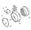
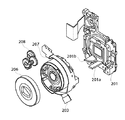
図2及び図3は、本実施形態に係るデジタルカメラの鏡筒の分解斜視図である。 2 and 3 are exploded perspective views of the lens barrel of the digital camera according to the present embodiment.
図中の201は、CCDホルダーユニットである。CCDホルダーユニット201は、CCDやローパスフィルタなどの光学及び撮像部を保持する枠であり、また直進キー201a及びバリアカム部201bが一体化して構成されている。202は非導電部材で構成された固定鏡筒であり、204は導電部材で構成された駆動環である。固定鏡筒202は、駆動環204を回転方向に自在に規制する。205は金属製の板バネから成る片寄せバネである。
201 in the figure is a CCD holder unit. The
CCDホルダーユニット201と固定鏡筒202で駆動環204を挟み込み、片寄せバネ205によりCCDホルダーユニット201方向に片寄せして駆動環204の光軸方向の位置を固定する。駆動環204と片寄せバネ205は直接接触しており、電気的には同電位につながっている。
The
206はバリアユニットであって、2枚のバリア羽根が開閉することにより、沈胴時にレンズを保護するように構成されている。
A
207はレンズ全群ユニット(図1のレンズ部17に相当)であって、レンズ全群を保持し、また内部に絞り及びシャッターを内蔵しており、鏡筒フレキ203を通した電気信号により内部の絞り及びシャッターを駆動する。レンズ全群ユニット207にある溝と直進キー201aが嵌合して、レンズ全群ユニット207が光軸方向前後に移動可能になっている。
<バリアユニット206の動作>
図4及び図5は、バリアユニット206の動作を説明するための図であり、図4がバリア開状態、図5がバリア閉状態を示している。
<Operation of
4 and 5 are diagrams for explaining the operation of the
図中の41は、バリアユニット206を駆動する部材であるバリア駆動環であり、42はバリア羽根(1)、43がバリア羽根(2)である。44は、開き方向にバリア駆動環41に負荷をかける開きバネ、45は閉じバネである。閉じバネ45は、フック状のバネであり、バリア駆動環41上に形成された突起部41aに係止しており、閉じバネ45の力によりバリア羽根(1)42を閉じ方向に引っ張って片寄せしている。バリア羽根(1)42とバリア羽根(2)43は、各回転軸の部分に形成されたギアで噛み合っており、バリア羽根(1)42が回転すれば反対方向にバリア羽根(2)43が回転するようになっている。
In the figure, 41 is a barrier drive ring which is a member for driving the
図4に示す開状態では、開きバネ44によりバリア駆動環41が右回りに回転することで、バリア羽根(1)42は突起部41aに押されて左回りの回転をする。これによってバリア羽根(2)も反対の右回りに回転し、バリアが開くことになる。
In the open state shown in FIG. 4, the
次にバリアを閉じる場合について説明する。バリアユニット206内のバリア駆動環41がバリアカム部201bのカム面に押し付けられることにより、バリア駆動環41が開きバネ44に反して左回りに回転する。この時、突起部41aが回転により下がってくるため、閉じバネ45の働きにより同時にバリア羽根(1)42が右回りに回転する。そしてギアの噛み合いによりバリア羽根(2)43も左回りに回転して二つの羽根42,43が合わさるところで止まる。図5に示す状態のところまでバリア駆動環41は回転可能であり、突起部41aはバリア羽根(1)42が止まっても更に回転して閉じバネ45を引っ張ることにより、バリアの閉じ力を更にチャージする。
Next, a case where the barrier is closed will be described. When the
以上のようにして、バリアユニット206がレンズ全群ユニット207と結合して一体に光軸方向前後に動くことにより、バリアカム部201bのカム面にバリアユニット206内のバリア駆動環41が当たる作用と開きバネ44のバネ力とによって、バリア駆動環41を回転させ、その回転と閉じバネ45により二枚のバリア羽根42,43が開閉するような仕組みとなっている。
As described above, when the
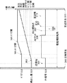
<バリア状態、レンズのリセット及び繰り出し状態の関係>
図6は、駆動環204の回転角度に対する、バリアの状態、フォーカスレンズのリセットタイミング及び繰り出し状態の関係を示す図である。
<Relationship between barrier state, lens reset and extended state>
FIG. 6 is a diagram illustrating the relationship between the barrier state, the focus lens reset timing, and the extended state with respect to the rotation angle of the
同図の横軸が駆動環204の回転角度であり、駆動環204の回転角によりフォーカスレンズが繰り出される。その繰り出し量を表すのが図中の321である。この時のバリアの状態を示すのが322であり、またリセット信号(PI信号:フォトインタラプタの出力)を示すのが323である。
The horizontal axis in the figure is the rotation angle of the
図中の300及び311は、それぞれ沈端突当て300と至近突当て311であり、メカ的に駆動環204のストッパーが突き当たることにより、駆動環204の回転を止めてフォーカスレンズが移動し過ぎないようになっている。
Reference numerals 300 and 311 in the figure denote a sinking end abutment 300 and a close-in abutment 311, respectively. When the stopper of the
沈端位置301からAFモータ114が回転を始めると、駆動環204の回転角度が位置302で示す一定角度まで、フォーカスレンズは停止し、位置302を境に繰り出しを始める。繰り出し開始直後の位置303でリセット信号323が“L”レベルから“H”レベルへ切り換わる。
When the
ここで、リセット信号323が切り換わる仕組みについて図7(a),(b),(c)を用いて説明する。図7(a),(b),(c)は、駆動環204とリセット部材であるフォトインタラプタ(PI)61との関係を示す図である。図6の沈端位置301に対応する状態が図7(a)に示され、図6のバリア開位置305に対応する状態が図7(b)に示され、図6の至近端位置310に対応する状態が図7(c)に示されている。同図中の204aは駆動環204と一体に形成された衝立部であり、フォトインタラプタ61内にはLEDとその受光センサーが配置されている。衝立部204aがそのLEDの発光を遮ったら“H”レベルを出力し、それ以外は“L”レベルを出力するといった仕組みになっている。
Here, a mechanism for switching the reset signal 323 will be described with reference to FIGS. 7A, 7B, and 7C. 7A, 7B, and 7C are views showing the relationship between the
上述したように位置303でリセット信号323が“H”レベルへと切り換わり、続いて更に繰り出していくと、バリアユニット206は、バリアカム部201bの働きにより、バリア閉位置304からバリア開位置305へ駆動環204が回転する位相で徐々にバリアを開く。バリア開位置305では完全にバリアが開き、またこの位置305を境にバリアカム部201bのカム面とバリア駆動環41の接触が離れる。
As described above, when the reset signal 323 is switched to the “H” level at the
駆動環204が逆転する場合も同様に、バリア開位置305からバリアカム部201bとバリア駆動環41が接し始め、バリア駆動環41が回転して開きバネ44のチャージを開始し、バリア駆動環41がバリア開位置305からバリア閉位置304に向かって動く時に徐々に閉じ動作を行う。この304から305の区間は開きバネ44のチャージ量が変化するため、どちらの方向に動く場合でも駆動環204の回転に必要なトルクがこの区間内で変化することになる。そしてこのトルク変化の大きい区間は、リセット信号323が“H”レベルになっている区間内にある。また、バリア開位置305から繰り出し側では、開きバネ44のバネ力は駆動環204の回転に影響を与えなくなる。
Similarly, when the
バリアが開いた位置305から更に駆動環204をフォーカスレンズが繰り出す方向に回転させると、位置306の位相から、衝立部204aが通過してフォトインタラプタ61を遮らなくなるため、リセット信号323が“L”レベルに切り換わる。この位置306をAFリセット位置とする。
When the driving
これより更に駆動環204を回転させて繰り出した位置307の位相をAFスキャン開始点に設定する。通常電源を入れた時や撮影後は、この位置307でフォーカスレンズを停止させておく。そこから少し駆動環204を回転させてフォーカスレンズを繰り出した位置308に無限遠のピント位置がある。さらに繰り出した位置309を定点位置としており、定点位置309とは、パンフォーカス撮影の時に無限遠からできるだけ長い範囲の近距離までピントが合うようにFナンバーと最小錯乱円により決められる位置である。パンフォーカス撮影やAFにより合焦位置が検出不可能な場合等のとき、この定点位置309で撮影を行う。さらに繰り出していくと段々焦点調節が近距離になっていき、至近端位置310に達する。
Further, the phase of the
<鏡筒の動作シーケンス>
I.電源オン時のシーケンス
次に、鏡筒を動かす時のシーケンスについて説明する。図8は、バッテリの残量が充分あると判断された場合の電源オン時のシーケンス図であり、図9は、バッテリの残量が少ないと判断された時の電源オン時のシーケンス図である。
<Operation sequence of lens barrel>
I. Next, a sequence for moving the lens barrel will be described. FIG. 8 is a sequence diagram when the power is turned on when it is determined that the remaining battery level is sufficient, and FIG. 9 is a sequence diagram when the power is turned on when it is determined that the remaining battery level is low. .
電源オン時に電源制御部112中のバッテリチェック回路がバッテリの電圧をチェックし、所定の閾値と比較して閾値以上ならばバッテリの残量が充分あると判断して図8のシーケンスを実行し、閾値以下であったら残量が少ないと判断して図9のシーケンスを実行する。
When the power is turned on, the battery check circuit in the power
バッテリ残量が充分ある場合(図8のシーケンス)には、ステッピングモータから成るAFモータ114に供給する電圧を3.0Vと高めに設定する。AFモータ114に供給するパルスの周波数は、それに使える割り込みの周期で決まっており、割り込みを300μsに設定する。
When the remaining battery level is sufficient (sequence in FIG. 8), the voltage supplied to the
そして、図8に示すように、まず沈端位置301から駆動周波数883PPSで8パルス分回転させ、次のパルスからは1111PPSに駆動周波数を変更して8パルス分回転させる。さらに駆動周波数を1667PPSに変更して回転を続ける。AFモータ114にステッピングモータを使っているため、このように段階的に加速制御することにより、プルイントルクでは回らない速度まで回転数を上げることができる。またこの場合、ステッピングモータの駆動周波数を上げることでトルクは下がってしまうため、これを補うためにステッピングモータに供給する電圧を3.0Vに上げることでトルクアップを図っている。
Then, as shown in FIG. 8, first, rotation is performed by 8 pulses at the drive frequency 883PPS from the
AFモータ114の回転により駆動環204を回転させフォーカスレンズを繰り出していき、リセット信号(PI)323が“L”レベルから“H”レベルに切り換わる位置303を過ぎた位置901でPI判定シーケンス(リセット信号の判定処理)に入るため、ここで最初の速度である周波数883PPSに減速する。この時点で再びバッテリチェックを行い、電圧が閾値より下がって残量が少ないと判断された場合には、ここから割り込み周波数を切り換えて図9のシーケンスに入る。電圧が充分である場合には再び883PPSから1111PPSへと8パルスずつ同じように2段階加速した後、1667PPSでAFモータ114を回転させる。そして、AFリセット位置306まで駆動させ、リセット後にまた2段階減速させ、1111PPSと883PPSで8パルスずつ駆動させる。
The driving
その後、割り込み周波数を800μsに、駆動電圧を2.7Vに切り換える。800μsの割り込み周波数で決まる駆動速度625PPSで4パルス駆動した後、1250PPSでスキャン開始点307の手前4パルスまで送り、また625PPSに減速してからスキャン開始点307で停止させる。
Thereafter, the interrupt frequency is switched to 800 μs and the drive voltage is switched to 2.7V. After four pulses are driven at a driving speed of 625 PPS determined by an interrupt frequency of 800 μs, the first four pulses before the
AFリセット位置306までを1667PPSで動かすのは、脱調してパルスのカウントとレンズの位置がずれてしまった場合でも、AFリセット位置306でリセットするためにレンズの位置に合わせてパルスのカウントを修正できるからである。また、バリア開の位置305まではバリアの開きバネ44のチャージを開放する力が加わるため、トルクに余裕が生じて高速で駆動することができる。また、位置305と位置306はできるだけ近い位置に配置している。リセット後は、レンズ位置のずれは許されないので、トルクに余裕がある1250PPSで動かすためにAFリセット位置306までの速度よりは低速で駆動することになる。
Moving to the AF reset
また、バッテリチェックで電圧が閾値以下の時は、図9に示すような駆動シーケンスとなる。 Further, when the voltage is equal to or lower than the threshold value in the battery check, a driving sequence as shown in FIG. 9 is performed.
図8と比較すれば分かるように、沈端位置301からAFリセット位置306後に減速するまでのAFモータ114に加える電圧と割り込み周波数、及び駆動周波数と加減速の段数を変更したものである。電圧は通常の2.7Vを加え、割り込み周波数を375μsに設定し、まずこの割り込み周波数で決まる889PPSで8パルス分駆動した後、1333PPSで駆動する。図8と同じ位置901でPI判定を行う。
As can be seen from comparison with FIG. 8, the voltage applied to the
この後の動作は、図8のPI判定時でバッテリ不十分のときと同じものになる。すなわち、1段889PPSで8パルス分駆動した後、AFリセット位置306まで1333PPSで駆動し、リセット後に8パルス分だけ889PPSに減速した後、割り込みを800μsに設定し、以下は同様に4パルス分だけ625PPSの後で1250PPSとなる。この場合も電圧は下げているが、AFリセットまではカウントの修正ができるのと、バネのチャージ力で負荷が減ることから、駆動周波数は、沈端位置301からAFリセット位置306までに使う1333PPSがリセット後に使う1250PPSより速くなるように設定している。
The subsequent operation is the same as when the battery is insufficient at the time of PI determination in FIG. That is, after driving for 8 pulses at 1st stage 889PPS, driving to 1333PPS until AF reset
以上、電源オン時のシーケンスについては、バッテリの残量が充分ある場合でも、少ない場合でも、AFリセット後に使う通常の駆動周波数よりAFリセットまでの駆動周波数を高くして速くAFモータ114を動かしているため、レンズの繰り出しが速くなり、起動時間を縮めることができる。このように高速化が可能なのは、AFモータ114に加わる負荷がバリア開位置305までは開きバネ44のバネ力により軽くなっているのでトルクに余裕があることと、リセットした後は通常の低い速度に落とすため、リセットする前までは脱調してレンズ位置がずれる恐れのある速度にしてもリセット時に修正ができるためである。
As described above, regarding the power-on sequence, whether the battery level is sufficient or low, the
AFリセット後は、このAFリセット位置306を基準にして、そこから何パルス分の位置までレンズを駆動させているかをカウントすることで、スキャン開始点や各被写体距離に対応した位置にレンズを繰り出すことができる。
After the AF reset, the lens is extended to a position corresponding to the scan start point and each subject distance by counting how many pulses the lens is driven from this AF reset
また、バッテリチェックにより残量が充分ある場合には、少ない場合に比べて多段階の加速制御をして高速にAFモータ114を駆動しているため、レンズの繰り出しを速くすることができ、沈胴時から電源オンして撮影可能となるまでの起動時間がより速くなる。
In addition, when the battery check has a sufficient remaining amount, since the
II.電源オフ時のシーケンス
次に、電源オフ時のシーケンスについて説明する。図10は、電源オフ時のシーケンス図である。
II. Next, a sequence when the power is turned off will be described. FIG. 10 is a sequence diagram when the power is turned off.
電源オン後または撮影後などのフォーカスレンズが停止している位置は、常にスキャン開始点307となるようになっている。このため、電源オフ時のシーケンスは、図10に示すように、スキャン開始点307から始まり、通常の割り込み800μs、電圧2.7V、625PPSで8パルス分繰り込み方向に駆動した後、1250PPSに加速する。そして、バリアが閉じ始まるバリア開位置305の直前の位置902で625PPSに減速する。この減速位置902は、バリア開位置305とAFリセット位置306の間にある。バリア開位置305より繰り込み側は、開きバネ44をチャージするために強い駆動トルクが必要となり、625PPSに減速したままで沈端位置301に停止するまで、この駆動速度で動かす。低速時のステッピングモータは電圧を変えなくてもトルクが強くなり脱調しにくくなる。
The position where the focus lens is stopped after the power is turned on or after photographing is always at the
バリア閉位置304を過ぎた後は、閉じバネ45のチャージも加わり更にAFモータ114の負荷は沈端位置301に近づくほど高くなる。このため、沈端付近で脱調する可能性が高くなるため、沈端付近にリセット位置303を設けている。位置303で沈端位置リセットを行った後は、そこから所定パルス分駆動した位置を沈端位置301としてそこまで駆動する。
After passing the
AFモータ114は多くのギアを用いて減速させているので、ギアのバックラッシュなどがあり、その結果、レンズの駆動にはモータの回転方向による往復差がある。このため、沈端位置301ではそのまま停止せずに、次の起動時の時間を短縮するため、この往復差を除去するのに必要な分のパルス数をAFモータ114に与えて逆転させて停止させる。
Since the
撮影時は、撮影時の機能に割り込みを多く使うことと、前述したようにトルクの余裕があることから、割り込み800μsのみを使用し、速度は625PPSと1250PPSで電圧も2.7Vで使用する。撮影待機時には、常にフォーカスレンズはスキャン開始点307で停止している。ここからAFスキャンを開始する。
At the time of shooting, since many interrupts are used for shooting functions and there is a margin of torque as described above, only the interrupt of 800 μs is used, the speed is 625 PPS and 1250 PPS, and the voltage is 2.7 V. At the time of shooting standby, the focus lens is always stopped at the
<撮影領域でのAFシーケンス>
図11は、撮影領域におけるAFシーケンスを示す図である。
<AF sequence in the shooting area>
FIG. 11 is a diagram illustrating an AF sequence in the imaging region.
同図において、スキャン開始点307でAFスキャンが開始され、AFスキャン中は625PPSの低速でフォーカスレンズを駆動する。このAFスキャンは、山登り方式のAFであり、フォーカスレンズを移動しながら各位置での画像の高周波成分を読み取り、その高周波成分の量を焦点評価値としてサンプリングして、そのピークを求める。そのため、フォーカスレンズは、スキャン開始点307から至近端位置310まで、またはマクロモードでない場合はその手前の決められた位置までを、画像をサンプリングしながら移動するため、低速で移動する必要がある。
In the figure, the AF scan is started at the
その後、至近端位置310でAFモータ114を反転させ(図11中の401)、ピークのある位置903を合焦点として、フォーカスレンズをその位置に向かって移動させる。まずモータ反転後は625PPSで4パルス分駆動し1250PPSに加速する加速制御で、合焦点903よりも所定のパルス数先まで行って反転する(402)。このとき、反転前の4パルスは625PPSで減速して停止し、反転後再び4パルス625PPSで始めて、1250PPSに加速し、停止直前4パルスを625PPSに減速駆動して、合焦点903で停止する。
Thereafter, the
この後、シャッターを動作させ撮影動作を行う(403)。撮影終了後にレリーズボタンを離すとAFリセット306の動作に入る。レンズは同じ625PPSを4パルス駆動した後1250PPSで繰り込み方向に駆動し、AFリセット位置306を過ぎてバリア開位置305の手前でAFモータ114を反転し(404)、繰り出し方向に駆動して再リセットした後、スキャン開始点307に戻る(405)。
Thereafter, the shutter is operated to perform a photographing operation (403). When the release button is released after the photographing is finished, the operation of AF reset 306 is started. After driving the same 625PPS for 4 pulses, the lens is driven in the retraction direction at 1250PPS, and after the AF reset
このように図11で説明した撮影領域においては、起動時の駆動周波数(図8:最高1667PPS、図9:最高1333PPS)に比べて、低い駆動周波数(最高1250PPS)で低速にフォーカスレンズを駆動するため、AFモータ114が脱調する恐れが少ない。また、AF動作中のスキャン開始点307から後はバリアの駆動領域を通らないので、AFモータ114に必要な駆動トルクは一定で低くなり、モータ114が脱調する恐れが少ない。また脱調が起こっていた場合でも、再リセットを行っているため、次の撮影ではレンズの位置が正しく修正されるため、レンズがずれた状態で撮影されることを回避することができる。
In this manner, in the imaging region described with reference to FIG. 11, the focus lens is driven at a low driving frequency (maximum 1250 PPS) at a lower speed than the driving frequency at startup (FIG. 8: maximum 1667 PPS, FIG. 9: maximum 1333 PPS). Therefore, there is little possibility that the
以上述べてきたように、本実施形態では、リセット信号(PI信号)の2箇所ある切り換り位置の一方(“L”から“H”)を沈胴位置近辺でバリアが完全に閉じきる位相と沈胴位置の間に設定し、もう一方(“H”から“L”)をバリアが開ききる位置とスキャン開始点の間に設定したので、バリアの開閉の行われる負荷変動の大きい領域の両端にリセット位置をおくことになり、ステッピングモータが負荷の変動により脱調してレンズの位置がずれた場合でも、直ちにリセットしてレンズの位置を正しい位置に復帰させることができる。さらに、リセットした後は負荷変動の大きい領域を通らないでオートフォーカスを行うことができる。 As described above, in this embodiment, one of the two switching positions (“L” to “H”) of the reset signal (PI signal) is set to a phase at which the barrier is completely closed in the vicinity of the retracted position. Since it is set between the retracted positions, and the other ("H" to "L") is set between the position where the barrier is fully opened and the scan start point, it is placed at both ends of the area where the load changes greatly where the barrier is opened and closed. A reset position is set, and even when the stepping motor steps out due to a load change and the lens position shifts, the lens position can be reset immediately to return the lens position to the correct position. Furthermore, after resetting, it is possible to perform autofocus without passing through a region with a large load fluctuation.
また、沈胴状態からの起動時では、バリアのバネ力によりレンズの負荷が小さくなるので、通常よりステッピングモータのパルスレートを上げて加速することにより、レンズの繰り出しが速くなり、沈胴時から電源オンして撮影可能となるまでの起動時間を縮めることができる。また逆に、沈胴時のバリア駆動領域では、バリアのバネ力をチャージするためレンズの負荷が大きくなるので、通常よりステッピングモータのパルスレートを下げて減速することにより、駆動トルクが高まり脱調を防止することができる。 Also, when starting from the retracted state, the load on the lens is reduced by the spring force of the barrier. Thus, it is possible to shorten the start-up time until shooting is possible. On the other hand, in the barrier drive area when retracted, the lens load increases because the spring force of the barrier is charged.By reducing the pulse rate of the stepping motor from the normal speed, the drive torque increases and step-out occurs. Can be prevented.
さらに、バッテリの残量によってバリア駆動領域でのステッピングモータのパルスレートを変えるようにしたので、例えばバッテリ残量が充分であるときは、パルスレートを上げて撮像レンズの繰り出し速度を速くし起動時間を短縮することが可能になる。また、バッテリ残量が充分でないときでも、パルスレートを下げて撮像レンズの駆動を低速で行うことにより撮影可能な状態にすることができ、バッテリ残量がなくなるぎりぎりまで撮影を続けることが可能になる。 Furthermore, the pulse rate of the stepping motor in the barrier drive area is changed according to the remaining battery level.For example, when the remaining battery level is sufficient, the start-up time can be increased by increasing the pulse rate and increasing the feeding speed of the imaging lens. Can be shortened. In addition, even when the remaining battery level is not enough, the imaging rate can be reduced by lowering the pulse rate and driving the imaging lens at a low speed, so that shooting can continue until the battery level is almost exhausted. Become.
なお、本発明は、上述した実施形態の装置に限定されず、複数の機器から構成されるシステムに適用しても、一つの機器から成る装置に適用してもよい。前述した実施形態の機能を実現するソフトウェアのプログラムコードを記憶した記憶媒体をシステムあるいは装置に供給し、そのシステムあるいは装置のコンピュータ(またはCPUやMPU)が記憶媒体に格納されたプログラムコードを読み出し実行することによっても、完成されることは言うまでもない。 Note that the present invention is not limited to the apparatus of the above-described embodiment, and may be applied to a system composed of a plurality of devices or an apparatus composed of a single device. A storage medium storing software program codes for realizing the functions of the above-described embodiments is supplied to a system or apparatus, and a computer (or CPU or MPU) of the system or apparatus reads and executes the program codes stored in the storage medium. Needless to say, it will be completed by doing.
この場合、記憶媒体から読み出されたプログラムコード自体が前述した実施形態の機能を実現することになり、そのプログラムコードを記憶した記憶媒体は本発明を構成することになる。プログラムコードを供給するための記憶媒体としては、例えば、フロッピー(登録商標)ディスク、ハードディスク、光ディスク、光磁気ディスク、CD−ROM、CD−R、磁気テープ、不揮発性のメモリカード、ROMを用いることができる。また、コンピュータが読み出したプログラムコードを実行することにより、前述した実施形態の機能が実現されるだけではなく、そのプログラムコードの指示に基づき、コンピュータ上で稼動しているOSなどが実際の処理の一部または全部を行い、その処理によって前述した実施形態の機能が実現される場合も含まれることは言うまでもない。 In this case, the program code itself read from the storage medium realizes the functions of the above-described embodiments, and the storage medium storing the program code constitutes the present invention. As a storage medium for supplying the program code, for example, a floppy (registered trademark) disk, hard disk, optical disk, magneto-optical disk, CD-ROM, CD-R, magnetic tape, nonvolatile memory card, ROM is used. Can do. In addition, by executing the program code read by the computer, not only the functions of the above-described embodiments are realized, but also the OS running on the computer based on the instruction of the program code performs the actual processing. Needless to say, a case where the function of the above-described embodiment is realized by performing part or all of the processing is also included.
さらに、記憶媒体から読み出されたプログラムコードが、コンピュータに挿入された機能拡張ボードやコンピュータに接続された機能拡張ユニットに備わるメモリに書き込まれた後、次のプログラムコードの指示に基づき、その拡張機能を拡張ボードや拡張ユニットに備わるCPUなどが処理を行って実際の処理の一部または全部を行い、その処理によって前述した実施形態の機能が実現される場合も含まれることは言うまでもない。 Furthermore, after the program code read from the storage medium is written to the memory provided in the function expansion board inserted in the computer or the function expansion unit connected to the computer, the program code is expanded based on the instruction of the next program code. It goes without saying that the functions of the above-described embodiments may be realized by performing some or all of the actual processing by the CPU or the like provided on the expansion board or the expansion unit.
11 CPU
12 信号処理回路
13 撮像素子
17 レンズ部
41 バリア駆動環
42 バリア羽根(1)
43 バリア羽根(2)
44 開きバネ
45 閉じバネ
113 AFリセット回路
114 AFモータ
204 駆動環
206 バリアユニット
207 レンズ全群ユニット
11 CPU
12
43 barrier blades (2)
44
Claims (5)
を有し、前記撮影レンズ部が沈胴位置から撮影領域まで移動する間に前記バリアが開き、
前記撮影領域から前記沈胴位置まで移動する間に前記バリアが閉じるように構成されたレ
ンズ鏡筒の位置制御を行う位置制御手段を備えた撮像装置であって、
衝立部が設けられ回転駆動する駆動環を備え、
前記バリアはバリア羽根を有し、前記バリアと前記撮影レンズ部との結合により前記バ
リア羽根が開閉し、前記撮影レンズ部は、前記駆動環により光軸方向に移動する構成であ
り、
前記位置制御手段は、
前記撮影レンズ部の位置を補正するための基準の位置である第1の基準位置と第2の基準位置を、前記駆動環の衝立部の検知に基づいて検出する検出手段を有し、
前記第1の基準位置は、前記駆動環が駆動していて前記バリア羽根が閉じ終わったバリア閉位置と前記沈胴位置との間の区間に設定され、 前記第2の基準位置は、前記駆動環が駆動していて前記バリア羽根が開き終わったバリア開位置と前記撮影領域との間の区間に設定されたことを特徴とする撮像装置。 A photographic lens unit that retracts into the imaging apparatus main body, and a barrier for protecting the photographic lens unit, the barrier opens while the photographic lens unit moves from the retracted position to the photographic region,
An imaging apparatus comprising position control means for performing position control of a lens barrel configured to close the barrier while moving from the imaging region to the retracted position,
A partition is provided with a drive ring that is driven to rotate,
The barrier has a barrier blade, the barrier blade opens and closes by coupling the barrier and the photographing lens unit, and the photographing lens unit is configured to move in the optical axis direction by the drive ring,
The position control means includes
Detecting means for detecting a first reference position and a second reference position, which are reference positions for correcting the position of the photographic lens unit, based on detection of a partition portion of the drive ring;
The first reference position is set to a section between the barrier closed position where the drive ring is driven and the barrier blades are closed and the retracted position, and the second reference position is the drive ring. Is set in a section between the barrier open position where the barrier blades have been opened and the imaging region .
前記バリア羽根の閉駆動時には前記駆動手段のパルスレートを低下して前記駆動手段を
減速制御し、前記バリア羽根の開駆動時には前記駆動手段のパルスレートを上げて前記駆
動手段を加速制御することを特徴とする請求項1に記載の撮像装置。 The drive ring is rotationally driven by a driving force of a driving means that is driven and controlled by pulses,
When the barrier blade is driven to be closed, the drive means is decreased to control the deceleration of the drive means, and when the barrier blade is opened, the drive means is increased to increase the pulse rate to control the drive means to be accelerated. The imaging apparatus according to claim 1, wherein the imaging apparatus is characterized.
により動作するように構成され、
前記電圧検出手段の検出結果に応じて、前記バリア羽根の開駆動時における前記駆動手
段のパルスレートを変更することを特徴とする請求項1又は2に記載の撮像装置。 Voltage detection means for detecting the voltage of the battery, the drive means is configured to operate with the power of the battery;
The voltage according to the detection result detecting means, the image pickup apparatus according to claim 1 or 2, characterized in that to change the pulse rate of the driving means in the open driving of the barrier blades.
を有し、前記撮影レンズ部が沈胴位置から撮影領域まで移動する間に前記バリアが開き、
前記撮影領域から前記沈胴位置まで移動する間に前記バリアが閉じるように構成されたレ
ンズ鏡筒の位置制御を行う撮像装置の制御方法であって、
前記撮像装置は、衝立部が設けられ回転駆動する駆動環を備え、前記バリアはバリア羽
根を有し、前記バリアと前記撮影レンズ部との結合により前記バリア羽根が開閉し、前記
撮影レンズ部は、前記駆動環により光軸方向に移動する構成であり、
前記駆動環の衝立部を検知手段により検知して、前記撮影レンズ部の第1の基準位置と
第2の基準位置を検出する検出工程を有し、
前記第1の基準位置は、前記駆動環が駆動していて前記バリア羽根が閉じ終わったバリア閉位置と前記沈胴位置との間の区間に設定され、 前記第2の基準位置は、前記駆動環が駆動していて前記バリア羽根が開き終わったバリア開位置と前記撮影領域との間の区間に設定され、
前記第1の基準位置と前記第2の基準位置に基づいて、前記撮影レンズ部の位置を補正する補正工程を
有することを特徴とする撮像装置の制御方法。 A photographic lens unit that retracts into the imaging apparatus main body, and a barrier for protecting the photographic lens unit, the barrier opens while the photographic lens unit moves from the retracted position to the photographic region,
A method of controlling an imaging apparatus that performs position control of a lens barrel configured to close the barrier while moving from the imaging region to the retracted position,
The imaging device includes a drive ring provided with a partition and rotationally driven. The barrier includes a barrier blade. The barrier blade opens and closes by coupling the barrier and the photographing lens unit. , Is configured to move in the optical axis direction by the drive ring,
A detection step of detecting a first reference position and a second reference position of the photographing lens unit by detecting a partition portion of the drive ring by a detection unit ;
The first reference position is set to a section between the barrier closed position where the drive ring is driven and the barrier blades are closed and the retracted position, and the second reference position is the drive ring. Is set to a section between the barrier opening position where the barrier blade has been opened and the imaging region,
A control method for an imaging apparatus, comprising: a correction step of correcting the position of the photographing lens unit based on the first reference position and the second reference position.
を有し、前記撮影レンズ部が沈胴位置から撮影領域まで移動する間に前記バリアが開き、
前記撮影領域から前記沈胴位置まで移動する間に前記バリアが閉じるように構成され、且
つ衝立部が設けられて回転駆動する駆動環を備え、前記バリアはバリア羽根を有し、前記
バリアと前記撮影レンズ部との結合により前記バリア羽根が開閉し、前記撮影レンズ部は
、前記駆動環により光軸方向に移動するように構成された撮像装置の制御方法を実行する
ための、コンピュータで読み取り可能なプログラムであって、
前記駆動環の衝立部を検知手段により検知して、前記撮影レンズ部の第1の基準位置と
第2の基準位置を検出する検出ステップを有し、
前記第1の基準位置は、前記駆動環が駆動していて前記バリア羽根が閉じ終わったバリア閉位置と前記沈胴位置との間の区間に設定され、 前記第2の基準位置は、前記駆動環が駆動していて前記バリア羽根が開き終わったバリア開位置と前記撮影領域との間の区間に設定され、
前記第1の基準位置と前記第2の基準位置に基づいて、前記撮影レンズ部の位置を補正
する補正ステップを
有することを特徴とするプログラム。 A photographic lens unit that retracts into the imaging apparatus main body, and a barrier for protecting the photographic lens unit, the barrier opens while the photographic lens unit moves from the retracted position to the photographic region,
The barrier is configured to be closed while moving from the imaging region to the retracted position, and includes a drive ring that is provided with a partition and is driven to rotate. The barrier includes barrier blades, and the barrier and the imaging The barrier blade opens and closes by coupling with the lens unit, and the photographing lens unit is computer-readable for executing a control method of the imaging apparatus configured to move in the optical axis direction by the drive ring. A program,
A detecting step of detecting a first reference position and a second reference position of the photographing lens unit by detecting a partition portion of the drive ring by a detection unit ;
The first reference position is set to a section between the barrier closed position where the drive ring is driven and the barrier blades are closed and the retracted position, and the second reference position is the drive ring. Is set to a section between the barrier opening position where the barrier blade has been opened and the imaging region,
A program comprising: a correction step of correcting the position of the photographing lens unit based on the first reference position and the second reference position.
Priority Applications (2)
| Application Number | Priority Date | Filing Date | Title |
|---|---|---|---|
| JP2003318913A JP4551640B2 (en) | 2003-09-10 | 2003-09-10 | Imaging apparatus, control method therefor, and control program |
| US10/935,285 US7742096B2 (en) | 2003-09-10 | 2004-09-08 | Image pickup apparatus including a lens barrel opening and closing a lens barrier protecting a lens and control method therefor, and control program for implementing the control method |
Applications Claiming Priority (1)
| Application Number | Priority Date | Filing Date | Title |
|---|---|---|---|
| JP2003318913A JP4551640B2 (en) | 2003-09-10 | 2003-09-10 | Imaging apparatus, control method therefor, and control program |
Publications (3)
| Publication Number | Publication Date |
|---|---|
| JP2005084545A JP2005084545A (en) | 2005-03-31 |
| JP2005084545A5 JP2005084545A5 (en) | 2009-02-19 |
| JP4551640B2 true JP4551640B2 (en) | 2010-09-29 |
Family
ID=34225340
Family Applications (1)
| Application Number | Title | Priority Date | Filing Date |
|---|---|---|---|
| JP2003318913A Expired - Fee Related JP4551640B2 (en) | 2003-09-10 | 2003-09-10 | Imaging apparatus, control method therefor, and control program |
Country Status (2)
| Country | Link |
|---|---|
| US (1) | US7742096B2 (en) |
| JP (1) | JP4551640B2 (en) |
Families Citing this family (12)
| Publication number | Priority date | Publication date | Assignee | Title |
|---|---|---|---|---|
| WO2006028003A1 (en) * | 2004-09-09 | 2006-03-16 | Seiko Precision Inc. | Lens barrier module and imaging device mounted with the same |
| JP4467577B2 (en) * | 2004-09-09 | 2010-05-26 | セイコープレシジョン株式会社 | Lens barrier device and imaging device provided with the same |
| JP5032775B2 (en) * | 2006-02-17 | 2012-09-26 | 富士フイルム株式会社 | Lens device |
| US7675832B2 (en) | 2006-03-01 | 2010-03-09 | Hitachi Media Electronics Co., Ltd. | Optical element feeding device driving method and optical disk apparatus |
| US8947526B2 (en) * | 2006-12-07 | 2015-02-03 | Sensormatic Electronics, LLC | Video surveillance system having communication acknowledgement nod |
| JP2008249892A (en) * | 2007-03-29 | 2008-10-16 | Fujinon Corp | Imaging apparatus |
| JP4974912B2 (en) * | 2008-01-22 | 2012-07-11 | キヤノン株式会社 | Imaging device |
| TW201021554A (en) * | 2008-11-19 | 2010-06-01 | Altek Corp | Method of auto-retracting lens of image capturing apparatus and control system using the same |
| JP2010191261A (en) * | 2009-02-19 | 2010-09-02 | Konica Minolta Opto Inc | Zoom lens device |
| FR2957160B1 (en) * | 2010-03-05 | 2012-05-11 | Valeo Vision | CAMERA AGENCED TO BE ONBOARD ON A VEHICLE |
| US9442350B2 (en) * | 2014-12-04 | 2016-09-13 | Ford Global Technologies, Llc | Hidden camera assembly with microprocessor control |
| JP6789733B2 (en) | 2016-09-06 | 2020-11-25 | キヤノン株式会社 | Image blur correction device, lens barrel, and image pickup device |
Citations (3)
| Publication number | Priority date | Publication date | Assignee | Title |
|---|---|---|---|---|
| JPH08327877A (en) * | 1995-06-01 | 1996-12-13 | Ricoh Co Ltd | Pulse motor control method for camera provided with lens standby position |
| JP2000347245A (en) * | 1999-06-03 | 2000-12-15 | Fuji Photo Optical Co Ltd | Camera with lens barrier |
| JP2001208956A (en) * | 2000-01-25 | 2001-08-03 | Fuji Photo Film Co Ltd | Digital camera |
Family Cites Families (20)
| Publication number | Priority date | Publication date | Assignee | Title |
|---|---|---|---|---|
| US5257053A (en) * | 1988-06-30 | 1993-10-26 | Asahi Kogaku Kogyo Kabushiki Kaisha | Position detecting device |
| US5455649A (en) * | 1990-05-31 | 1995-10-03 | Canon Kabushiki Kaisha | Optical system controlling apparatus |
| JPH05215951A (en) * | 1992-02-03 | 1993-08-27 | Olympus Optical Co Ltd | Encoder device |
| US5953062A (en) * | 1992-06-05 | 1999-09-14 | Canon Kabushiki Kaisha | Exposure control device for optical apparatus |
| JP3622220B2 (en) | 1994-02-04 | 2005-02-23 | 株式会社ニコン | camera |
| US6392703B1 (en) * | 1995-02-28 | 2002-05-21 | Canon Kabushiki Kaisha | Optical apparatus for forming an object image on a sensing element |
| JPH09211528A (en) | 1996-02-01 | 1997-08-15 | Olympus Optical Co Ltd | Camera |
| JP3842876B2 (en) * | 1996-09-27 | 2006-11-08 | 株式会社リコー | Digital camera |
| US6104509A (en) * | 1996-10-21 | 2000-08-15 | Fuji Photo Film Co., Ltd. | Method for correcting quantity of emitted light |
| JPH11261857A (en) * | 1998-03-11 | 1999-09-24 | Canon Inc | Image pickup device |
| US6727954B1 (en) * | 1998-08-12 | 2004-04-27 | Minolta Co., Ltd. | Electronic camera and image processing system |
| US6950139B2 (en) * | 1999-01-22 | 2005-09-27 | Nikon Corporation | Image reading device and storage medium storing control procedure for image reading device |
| US6982813B2 (en) * | 2000-02-16 | 2006-01-03 | Minolta Co., Ltd. | Light quantity correction method for exposing device, and image forming device |
| JP2002214506A (en) | 2001-01-15 | 2002-07-31 | Olympus Optical Co Ltd | Camera |
| EP1845701A1 (en) * | 2001-01-31 | 2007-10-17 | FUJIFILM Corporation | Digital camera and method of controlling operation of same |
| TW495641B (en) * | 2001-06-06 | 2002-07-21 | Arc Design Inc | Two zone automatic lens focusing system for digital still cameras |
| JP4298191B2 (en) * | 2001-08-30 | 2009-07-15 | 株式会社リコー | Program to be executed by camera and computer |
| JP4185729B2 (en) * | 2002-08-06 | 2008-11-26 | キヤノン株式会社 | Lens barrel and camera |
| JP4478377B2 (en) * | 2002-09-03 | 2010-06-09 | キヤノン株式会社 | Automatic focusing method and imaging apparatus |
| JP3959690B2 (en) * | 2003-10-01 | 2007-08-15 | ソニー株式会社 | Imaging apparatus and imaging method |
-
2003
- 2003-09-10 JP JP2003318913A patent/JP4551640B2/en not_active Expired - Fee Related
-
2004
- 2004-09-08 US US10/935,285 patent/US7742096B2/en not_active Expired - Fee Related
Patent Citations (3)
| Publication number | Priority date | Publication date | Assignee | Title |
|---|---|---|---|---|
| JPH08327877A (en) * | 1995-06-01 | 1996-12-13 | Ricoh Co Ltd | Pulse motor control method for camera provided with lens standby position |
| JP2000347245A (en) * | 1999-06-03 | 2000-12-15 | Fuji Photo Optical Co Ltd | Camera with lens barrier |
| JP2001208956A (en) * | 2000-01-25 | 2001-08-03 | Fuji Photo Film Co Ltd | Digital camera |
Also Published As
| Publication number | Publication date |
|---|---|
| US20050052560A1 (en) | 2005-03-10 |
| US7742096B2 (en) | 2010-06-22 |
| JP2005084545A (en) | 2005-03-31 |
Similar Documents
| Publication | Publication Date | Title |
|---|---|---|
| JP5073172B2 (en) | Digital camera and portable information terminal device | |
| US7203011B2 (en) | Lens device, imaging device using the same and cell-phone with camera using the same | |
| JP4447491B2 (en) | Lens barrel, lens driving device, camera, and portable information terminal device | |
| US7365789B2 (en) | Autofocus method and apparatus | |
| US7518649B2 (en) | Image pickup apparatus and control method therefor, and control program | |
| JP4551640B2 (en) | Imaging apparatus, control method therefor, and control program | |
| EP2423725A1 (en) | Lens driving apparatus and control method thereof, and image capturing apparatus and control method thereof | |
| JP2006243605A (en) | Lens barrel, camera and personal digital assistant device using lens barrel | |
| JP5178186B2 (en) | Lens position control device and control method thereof | |
| US11953819B2 (en) | Lens apparatus and image pickup apparatus | |
| JPH08160287A (en) | Autofocusing device | |
| JP2005102199A (en) | Imaging apparatus and its control method, and control program | |
| US20060291078A1 (en) | Lens barrel and image pickup apparatus | |
| JP2008003501A (en) | Lens driving device | |
| JP4923691B2 (en) | Lens barrel and imaging device | |
| JP4768287B2 (en) | Lens barrel, camera, portable information terminal device, and image input device | |
| EP1667433B1 (en) | Imaging device, control method thereof, and control program | |
| JP4744253B2 (en) | Auto focus camera | |
| JP4541722B2 (en) | Imaging device | |
| JP6685702B2 (en) | Imaging device and lens drive control method | |
| JP2006091438A (en) | Lens driving device and camera | |
| JP5219670B2 (en) | Optical apparatus and lens position detection method | |
| JP2005106848A (en) | Imaging device | |
| JP2003315652A (en) | Lens barrel and image pickup unit | |
| JP2002131610A (en) | Image pickup apparatus |
Legal Events
| Date | Code | Title | Description |
|---|---|---|---|
| RD03 | Notification of appointment of power of attorney |
Free format text: JAPANESE INTERMEDIATE CODE: A7423 Effective date: 20060417 |
|
| A521 | Request for written amendment filed |
Free format text: JAPANESE INTERMEDIATE CODE: A523 Effective date: 20060907 |
|
| A621 | Written request for application examination |
Free format text: JAPANESE INTERMEDIATE CODE: A621 Effective date: 20060907 |
|
| RD05 | Notification of revocation of power of attorney |
Free format text: JAPANESE INTERMEDIATE CODE: A7425 Effective date: 20070626 |
|
| A521 | Request for written amendment filed |
Free format text: JAPANESE INTERMEDIATE CODE: A523 Effective date: 20090106 |
|
| A977 | Report on retrieval |
Free format text: JAPANESE INTERMEDIATE CODE: A971007 Effective date: 20091008 |
|
| A131 | Notification of reasons for refusal |
Free format text: JAPANESE INTERMEDIATE CODE: A131 Effective date: 20091013 |
|
| A521 | Request for written amendment filed |
Free format text: JAPANESE INTERMEDIATE CODE: A523 Effective date: 20091214 |
|
| A131 | Notification of reasons for refusal |
Free format text: JAPANESE INTERMEDIATE CODE: A131 Effective date: 20100330 |
|
| A521 | Request for written amendment filed |
Free format text: JAPANESE INTERMEDIATE CODE: A523 Effective date: 20100531 |
|
| TRDD | Decision of grant or rejection written | ||
| A01 | Written decision to grant a patent or to grant a registration (utility model) |
Free format text: JAPANESE INTERMEDIATE CODE: A01 Effective date: 20100706 |
|
| A01 | Written decision to grant a patent or to grant a registration (utility model) |
Free format text: JAPANESE INTERMEDIATE CODE: A01 |
|
| A61 | First payment of annual fees (during grant procedure) |
Free format text: JAPANESE INTERMEDIATE CODE: A61 Effective date: 20100712 |
|
| R150 | Certificate of patent or registration of utility model |
Free format text: JAPANESE INTERMEDIATE CODE: R150 |
|
| FPAY | Renewal fee payment (event date is renewal date of database) |
Free format text: PAYMENT UNTIL: 20130716 Year of fee payment: 3 |
|
| LAPS | Cancellation because of no payment of annual fees |