JP4546250B2 - Guide wire control catheter for passing through an obstruction and method of use associated therewith - Google Patents
Guide wire control catheter for passing through an obstruction and method of use associated therewith Download PDFInfo
- Publication number
- JP4546250B2 JP4546250B2 JP2004555478A JP2004555478A JP4546250B2 JP 4546250 B2 JP4546250 B2 JP 4546250B2 JP 2004555478 A JP2004555478 A JP 2004555478A JP 2004555478 A JP2004555478 A JP 2004555478A JP 4546250 B2 JP4546250 B2 JP 4546250B2
- Authority
- JP
- Japan
- Prior art keywords
- wire
- catheter
- guide wire
- control
- control catheter
- Prior art date
- Legal status (The legal status is an assumption and is not a legal conclusion. Google has not performed a legal analysis and makes no representation as to the accuracy of the status listed.)
- Expired - Fee Related
Links
- GQDYKYGFCJNFOU-UHFFFAOYSA-N CCCCC1NC1 Chemical compound CCCCC1NC1 GQDYKYGFCJNFOU-UHFFFAOYSA-N 0.000 description 1
Images


Classifications
-
- A—HUMAN NECESSITIES
- A61—MEDICAL OR VETERINARY SCIENCE; HYGIENE
- A61M—DEVICES FOR INTRODUCING MEDIA INTO, OR ONTO, THE BODY; DEVICES FOR TRANSDUCING BODY MEDIA OR FOR TAKING MEDIA FROM THE BODY; DEVICES FOR PRODUCING OR ENDING SLEEP OR STUPOR
- A61M25/00—Catheters; Hollow probes
- A61M25/01—Introducing, guiding, advancing, emplacing or holding catheters
- A61M25/0105—Steering means as part of the catheter or advancing means; Markers for positioning
- A61M25/0133—Tip steering devices
- A61M25/0147—Tip steering devices with movable mechanical means, e.g. pull wires
-
- A—HUMAN NECESSITIES
- A61—MEDICAL OR VETERINARY SCIENCE; HYGIENE
- A61M—DEVICES FOR INTRODUCING MEDIA INTO, OR ONTO, THE BODY; DEVICES FOR TRANSDUCING BODY MEDIA OR FOR TAKING MEDIA FROM THE BODY; DEVICES FOR PRODUCING OR ENDING SLEEP OR STUPOR
- A61M25/00—Catheters; Hollow probes
- A61M25/01—Introducing, guiding, advancing, emplacing or holding catheters
- A61M25/0105—Steering means as part of the catheter or advancing means; Markers for positioning
- A61M25/0133—Tip steering devices
- A61M25/0138—Tip steering devices having flexible regions as a result of weakened outer material, e.g. slots, slits, cuts, joints or coils
-
- A—HUMAN NECESSITIES
- A61—MEDICAL OR VETERINARY SCIENCE; HYGIENE
- A61M—DEVICES FOR INTRODUCING MEDIA INTO, OR ONTO, THE BODY; DEVICES FOR TRANSDUCING BODY MEDIA OR FOR TAKING MEDIA FROM THE BODY; DEVICES FOR PRODUCING OR ENDING SLEEP OR STUPOR
- A61M25/00—Catheters; Hollow probes
- A61M25/01—Introducing, guiding, advancing, emplacing or holding catheters
- A61M25/0105—Steering means as part of the catheter or advancing means; Markers for positioning
- A61M25/0133—Tip steering devices
- A61M25/0144—Tip steering devices having flexible regions as a result of inner reinforcement means, e.g. struts or rods
-
- A—HUMAN NECESSITIES
- A61—MEDICAL OR VETERINARY SCIENCE; HYGIENE
- A61B—DIAGNOSIS; SURGERY; IDENTIFICATION
- A61B17/00—Surgical instruments, devices or methods, e.g. tourniquets
- A61B17/22—Implements for squeezing-off ulcers or the like on the inside of inner organs of the body; Implements for scraping-out cavities of body organs, e.g. bones; Calculus removers; Calculus smashing apparatus; Apparatus for removing obstructions in blood vessels, not otherwise provided for
- A61B2017/22094—Implements for squeezing-off ulcers or the like on the inside of inner organs of the body; Implements for scraping-out cavities of body organs, e.g. bones; Calculus removers; Calculus smashing apparatus; Apparatus for removing obstructions in blood vessels, not otherwise provided for for crossing total occlusions, i.e. piercing
-
- A—HUMAN NECESSITIES
- A61—MEDICAL OR VETERINARY SCIENCE; HYGIENE
- A61M—DEVICES FOR INTRODUCING MEDIA INTO, OR ONTO, THE BODY; DEVICES FOR TRANSDUCING BODY MEDIA OR FOR TAKING MEDIA FROM THE BODY; DEVICES FOR PRODUCING OR ENDING SLEEP OR STUPOR
- A61M25/00—Catheters; Hollow probes
- A61M25/01—Introducing, guiding, advancing, emplacing or holding catheters
- A61M2025/0183—Rapid exchange or monorail catheters
-
- A—HUMAN NECESSITIES
- A61—MEDICAL OR VETERINARY SCIENCE; HYGIENE
- A61M—DEVICES FOR INTRODUCING MEDIA INTO, OR ONTO, THE BODY; DEVICES FOR TRANSDUCING BODY MEDIA OR FOR TAKING MEDIA FROM THE BODY; DEVICES FOR PRODUCING OR ENDING SLEEP OR STUPOR
- A61M25/00—Catheters; Hollow probes
- A61M25/10—Balloon catheters
- A61M2025/1043—Balloon catheters with special features or adapted for special applications
- A61M2025/1047—Balloon catheters with special features or adapted for special applications having centering means, e.g. balloons having an appropriate shape
-
- A—HUMAN NECESSITIES
- A61—MEDICAL OR VETERINARY SCIENCE; HYGIENE
- A61M—DEVICES FOR INTRODUCING MEDIA INTO, OR ONTO, THE BODY; DEVICES FOR TRANSDUCING BODY MEDIA OR FOR TAKING MEDIA FROM THE BODY; DEVICES FOR PRODUCING OR ENDING SLEEP OR STUPOR
- A61M25/00—Catheters; Hollow probes
- A61M25/01—Introducing, guiding, advancing, emplacing or holding catheters
- A61M25/0105—Steering means as part of the catheter or advancing means; Markers for positioning
- A61M25/0133—Tip steering devices
- A61M25/0136—Handles therefor
-
- A—HUMAN NECESSITIES
- A61—MEDICAL OR VETERINARY SCIENCE; HYGIENE
- A61M—DEVICES FOR INTRODUCING MEDIA INTO, OR ONTO, THE BODY; DEVICES FOR TRANSDUCING BODY MEDIA OR FOR TAKING MEDIA FROM THE BODY; DEVICES FOR PRODUCING OR ENDING SLEEP OR STUPOR
- A61M25/00—Catheters; Hollow probes
- A61M25/01—Introducing, guiding, advancing, emplacing or holding catheters
- A61M25/0172—Exchanging a guidewire while keeping the catheter in place
Landscapes
- Health & Medical Sciences (AREA)
- Life Sciences & Earth Sciences (AREA)
- Engineering & Computer Science (AREA)
- Biomedical Technology (AREA)
- Pulmonology (AREA)
- Anesthesiology (AREA)
- Biophysics (AREA)
- Heart & Thoracic Surgery (AREA)
- Hematology (AREA)
- Animal Behavior & Ethology (AREA)
- General Health & Medical Sciences (AREA)
- Public Health (AREA)
- Veterinary Medicine (AREA)
- Mechanical Engineering (AREA)
- Media Introduction/Drainage Providing Device (AREA)
Description
本発明は、血管内の閉塞部を通過するために使用される装置および方法に関し、より特定の実施形態としては、血管内の慢性完全閉塞部を通過するように案内ワイヤを制御するためのカテーテルに関する。 The present invention relates to an apparatus and method used to pass through an occlusion in a blood vessel, and more particularly, a catheter for controlling a guide wire to pass through a chronic total occlusion in a blood vessel. About.
慢性完全閉塞(CTO)は、完全に閉塞してしまうことにより通常の血流を妨げる血管病変である。こうした閉塞は、冠血管を含む患者の血管系、動脈、および、静脈、並びに、頚動脈、腎動脈、脳動脈、腸骨動脈、大腿骨動脈、膝窩動脈、その他、抹消動脈のどこでも起こりえる。 Chronic total occlusion (CTO) is a vascular lesion that interferes with normal blood flow by becoming completely occluded. Such occlusion can occur anywhere in the patient's vasculature, arteries, and veins, including coronary vessels, and carotid, renal, cerebral, iliac, femoral, popliteal, and other peripheral arteries.
典型的には、CTOは、数週間から数ヶ月、或いは、それ以上の期間をかけて生じる。こうした遮蔽は、患者の血管系内におけるその位置に応じて医学上深刻な結果を含んでいる。例えば、血液を心臓へ供給する冠血管における遮蔽は、心臓に障害を引き起こしてしまう。 Typically, CTO occurs over a period of weeks to months or longer. Such shielding has serious medical consequences depending on its location within the patient's vasculature. For example, shielding in the coronary vessels that supply blood to the heart can cause damage to the heart.
また、殆どの病変は長い時間をかけて群発するので、病変の末端側の虚血性組織は幾つかの側副循環を形成する時間がある。これが冠動脈の場合、これら側副循環が基端側の動脈から形成されて末端側の動脈に繋がったり(「同側側副循環」)、或いは、別の主要な動脈枝から形成されて末端側の動脈に繋がったりする(「対側側副循環」)。そして、最終的に病変が完全閉塞になると、側副循環は、典型的には、末端側の組織を生かしておくのには十分であるが、虚血状態にある。心循環では、この虚血性組織が狭心症を引き起こす。したがって、末端側の組織への血流を確立し直すことが好ましい。 Also, since most lesions cluster over time, the ischemic tissue on the distal side of the lesion has time to form several collateral circulations. If this is a coronary artery, these collateral circulations are formed from proximal arteries and connected to distal arteries ("Isolateral collateral circulation"), or are formed from other major arterial branches and are distal To the arteries ("contralateral collateral circulation"). And when the lesion eventually becomes totally occluded, the collateral circulation is typically ischemic, although it is sufficient to keep the distal tissue alive. In the cardiac circulation, this ischemic tissue causes angina. Therefore, it is preferable to reestablish blood flow to the distal tissue.
血管内の遮蔽を通る血流や血管内の遮蔽周りの血流を確立し直したりするのに、現在、数々の外科処置が利用されている。こうした外科処置には、冠動脈バイパス手術やバルーン血管形成術がある。バルーン血管形成術は、典型的には、案内ワイヤを伝って閉塞病変部にバルーンカテーテルを挿入し、病変部のところでバルーンを拡張させ、必要であれば、拡張させた病変部を開いたままに維持するために拡張させた病変にステントを配置するといった処置を含む。 Numerous surgical procedures are currently used to reestablish blood flow through and around the intravascular shield. Such surgical procedures include coronary artery bypass surgery and balloon angioplasty. Balloon angioplasty typically involves inserting a balloon catheter into the occluded lesion over a guide wire, expanding the balloon at the lesion, and leaving the expanded lesion open if necessary. This includes procedures such as placing a stent in a lesion that has been expanded for maintenance.
案内ワイヤ14のような案内ワイヤは初めからあった内腔を辿るのではなく病変組織を貫通しなければならないので、図1Aに示した血管12内の閉塞部10のような慢性完全閉塞部を通過させることは、部分的にしか閉塞されていない病変部を通過させるよりも難しい。また、合併症が生じる可能性もある。例えば、図1Bに示したように、案内ワイヤ14の末端側端部および末端側先端が病変部に入り込むのに十分な支持力または剛性を有しておらず、その端部が曲がってしまうことがある。或いは、図1Cに示したように、特に、案内ワイヤ14の末端側端部および末端側先端が閉塞部10の方を向いていないときには、案内ワイヤ14が血管12に穴を開けてしまうこともある。仮に、図1Dおよび図1Eに示したように、案内ワイヤ14が閉塞部10に入り込む際の該案内ワイヤ14の初期の方向付けを助けるために、案内ワイヤ14がその先端に予め曲がり14aを形成されている場合であっても、病変部の内部組織が案内ワイヤ14に閉塞部10内で望ましくない道筋をとらせてしまうことがある。そして、案内ワイヤが閉塞部を成功裏に通過できなかった場合、閉塞部を拡張して治療するために、バルーン血管形成カテーテルのようなそれに続く治療器具を閉塞部を通過するように前進させることができない。
Since a guide wire such as
また、図1F〜図1Hは、分岐部のところの閉塞部10を通過させようとしたときの同様の問題を示している。ここで、図1Gは、病変部に入り込むのには不十分な支持力または剛性しか有しておらず、端部が曲がってしまった案内ワイヤ14の末端側端部および末端側先端を示し、図1Hは、分岐部のところの血管に穴を開けてしまった案内ワイヤ14を示している。
1F to 1H show a similar problem when trying to pass the blocking
こうした理由から、CTOを通過して治療するのが成功する率は、部分的にしか閉塞していない病変部、特に、冠CTOに対する率よりも相当に低い。さらに、従来の案内ワイヤに完全閉塞部を成功裏に通過させることができたとしても、一部の医師には、非常に多くの時間と熟練が要求される。したがって、閉塞部を通過させるための改良されたシステムおよび方法が必要とされている。 For these reasons, the rate of successful treatment through the CTO is significantly lower than the rate for lesions that are only partially occluded, especially coronary CTO. Furthermore, even if a complete occlusion can be successfully passed through a conventional guide wire, some doctors require a great deal of time and skill. Accordingly, there is a need for improved systems and methods for passing occlusions.
本発明によれば、閉塞部を通過させる方法および装置が提供される。 According to the present invention, a method and apparatus for passing an obstruction is provided.
本発明の1つの形態では、血管内での案内ワイヤの前進を制御するためのワイヤ制御カテーテルが提供される。このワイヤ制御カテーテルは、該カテーテルの末端側先端部分を関節のように曲げるためのシングル制御ワイヤと、該シングル制御ワイヤを受容するためのシングル制御ワイヤルーメンを備えたシャフトとを具備する。 In one form of the invention, a wire control catheter is provided for controlling the advancement of a guide wire within a blood vessel. The wire control catheter includes a single control wire for bending the distal tip of the catheter like a joint and a shaft with a single control wire lumen for receiving the single control wire.
また、本発明の別の形態では、血管内での案内ワイヤの前進を制御するためのワイヤ制御カテーテルは、案内ワイヤルーメンと制御ワイヤルーメンとを画成すると共に屈曲可能な末端側先端部分を備えたシャフトと、前記末端側先端部分を屈曲させるための手段と、前記シャフトの末端部分に設けられたセンタリング器具とを具備する。 In another aspect of the invention, a wire control catheter for controlling the advancement of a guide wire within a blood vessel defines a guide wire lumen and a control wire lumen and includes a bendable distal tip portion. A shaft, means for bending the distal tip portion, and a centering device provided at the distal portion of the shaft.
本発明のさらに別の形態では、血管内での案内ワイヤの前進を制御するためのワイヤ制御カテーテルは、該カテーテルの末端側先端と該カテーテルの基端側端部との間で延びる制御ワイヤルーメンを画成する第1シャフト部分と、前記制御ワイヤルーメンよりも実質的に短い案内ワイヤルーメンを画成する第2シャフト部分と、屈曲可能な末端側先端部分とを具備する。 In yet another aspect of the invention, a wire control catheter for controlling the advancement of a guide wire within a blood vessel includes a control wire lumen that extends between the distal tip of the catheter and the proximal end of the catheter. , A second shaft portion defining a guide wire lumen that is substantially shorter than the control wire lumen, and a bendable distal tip portion.
本発明のさらに別の形態では、血管内での案内ワイヤの前進を制御するためのシステムが提供される。このシステムは、案内ワイヤルーメンと制御ワイヤルーメンと該制御ワイヤルーメン内の制御ワイヤとを備えたワイヤ制御カテーテルと、前記案内ワイヤルーメン内に配置可能なスライドシースカテーテルとを具備する。 In yet another aspect of the invention, a system is provided for controlling the advancement of a guide wire within a blood vessel. The system includes a wire control catheter comprising a guide wire lumen, a control wire lumen, and a control wire within the control wire lumen, and a slide sheath catheter positionable within the guide wire lumen.
本発明のさらに別の形態では、血管を治療する方法が提供される。この方法は、案内ワイヤを血管内に挿入する工程と、制御カテーテルの末端側先端が血管内の閉塞部の近くに来るまで該制御カテーテルを案内ワイヤを伝って前進させる工程と、該制御カテーテルの末端側先端を屈曲させる工程と、閉塞部を通過するように案内ワイヤを前進させる工程とを具備する。 In yet another aspect of the invention, a method for treating a blood vessel is provided. The method includes inserting a guide wire into the blood vessel, advancing the control catheter along the guide wire until the distal tip of the control catheter is near an occlusion in the blood vessel, A step of bending the distal tip, and a step of advancing the guide wire so as to pass through the blocking portion.
本発明のさらに別の形態では、血管内での案内ワイヤの前進を制御するためのワイヤ制御カテーテルは、屈曲可能な末端側先端を備えたシャフトと、該シャフトの一部に連結された予拡張バルーンとを具備する。 In yet another aspect of the invention, a wire control catheter for controlling the advancement of a guide wire within a blood vessel includes a shaft with a bendable distal tip and a pre-expansion coupled to a portion of the shaft. And a balloon.
本発明のその他の目的や利点の一部は以下の説明に記載されており、一部は以下の説明から自明であり、或いは、本発明の実施によって知ることができる。本発明の目的および利点は、特に、特許請求の範囲で挙げている要素や組合せから把握したり理解したりできるであろう。 Some of the other objects and advantages of the present invention are described in the following description, and some are obvious from the following description, or can be known by practice of the present invention. The objects and advantages of the invention may be realized and understood from the elements and combinations particularly pointed out in the appended claims.
上述した一般的な説明や後述する詳細な説明は、共に、例であったり、例示であったりするだけものもであって、特許請求の範囲に係る発明を限定することを意図したものではない。 Both the general description and the detailed description to be described later are merely examples and examples, and are not intended to limit the invention according to the claims. .
本明細書に組み込まれて本明細書の一部をなす添付の図面は、本発明の幾つかの実施形態を示しており、以下の説明と合わせて、本発明の原理を説明するためのものである。 The accompanying drawings, which are incorporated in and constitute a part of this specification, illustrate several embodiments of the present invention and together with the following description, serve to explain the principles of the invention. It is.
以下、添付の図面に示されている本発明の実施形態の例を詳細に参照する。なお、図面では、同じ部分や同様の部分にはできる限り同じ参照符号を付してある。 Reference will now be made in detail to exemplary embodiments of the present invention as illustrated in the accompanying drawings. In the drawings, the same reference numerals are given to the same or similar parts as much as possible.
本発明の実施形態によれば、血管内の病変部を通過するようなワイヤの前進中に案内ワイヤのフレキシブルな端部領域に追加の支持力を提供するシステムおよび方法が提供される。また、別の実施形態によれば、病変部を通過している間において案内ワイヤの先端が前進する方向を制御するシステムおよび方法が提供される。これら実施形態は、血管に穴を開けてしまったり内膜下の組織に入り込んでしまったりする危険性を最小限に抑えつつ病変部を成功裏に通過することを改良すべきものである。 In accordance with embodiments of the present invention, systems and methods are provided that provide additional support to the flexible end region of the guide wire during advancement of the wire as it passes through a lesion in a blood vessel. Another embodiment provides a system and method for controlling the direction in which the distal end of the guide wire advances while passing through a lesion. These embodiments should improve the successful passage of the lesion while minimizing the risk of puncturing the blood vessel and entering the subintimal tissue.
なお、本明細書において用いる「閉塞」「遮断」「狭窄」「病変」とは、血管の完全閉塞、血管の部分閉塞、狭窄、塞栓、血栓、プラーク、破片、その他、血管内腔を少なくとも部分的に閉塞してしまう特定のものをいう。さらに、本明細書において用いる「基端」とは、患者の身体の外に残る端部に最も近い装置の部分をいい、「末端」とは、患者の体内に挿入される端部に最も近い部分をいう。 As used herein, “occlusion”, “blocking”, “stenosis”, and “lesion” mean complete occlusion of a blood vessel, partial occlusion of a blood vessel, stenosis, embolism, thrombus, plaque, fragment, etc. It refers to a specific thing that is blocked. Further, as used herein, “proximal” refers to the portion of the device that is closest to the end that remains outside the patient's body, and “terminal” is closest to the end that is inserted into the patient's body. Say part.
また、ここで開示する方法およびシステムは、特に、病気の状態にある伏在静脈グラフト(SVG)、伏在動脈、冠動脈、腎動脈、脳動脈、腸骨動脈、大腿動脈、ポピティール、その他、抹消動脈といった病気の状態にある血管での使用に適している。しかしながら、これら方法やシステムをその他の血管のようなその他の領域で使用できるように合わせることもできる。 The disclosed methods and systems also include saphenous vein grafts (SVG), saphenous arteries, coronary arteries, renal arteries, cerebral arteries, iliac arteries, femoral arteries, popital, etc. Suitable for use in diseased blood vessels such as arteries. However, these methods and systems can be adapted for use in other areas such as other blood vessels.
本発明の1つの実施形態によれば、遮蔽部を通るように案内ワイヤを案内すると共に支持するためのワイヤ制御カテーテルが提供される。ここで具体的に説明し、図10に示すように、オーバーザワイヤ(OTW)型のカテーテル130の好ましい実施形態を開示する。OTWカテーテル130は、案内ワイヤルーメン134を備えたフルレングスのシャフト132を有する(図9Aおよび図9B参照)。「フルレングス」とは、カテーテル130および案内ワイヤ114(図10には示していない)を制御するのに使用されるハンドル組立体(図10には示していない)のところの基端部までシャフト132の全長に亘って案内ワイヤが延在することを意味する。
According to one embodiment of the present invention, a wire control catheter is provided for guiding and supporting a guide wire through a shield. A preferred embodiment of an over-the-wire (OTW)
図9Aおよび図9Bに示したように、案内ワイヤルーメン134は、好ましくは、案内ワイヤ114が動きやすいように、例えば、PTFEからなる滑らかな内側ライナー136によって形成される。さらに、シャフト132は、制御ワイヤ142用のルーメン138を有する。制御ワイヤ142は、後に詳細に説明するように、OTWカテーテル130の方向変換可能な末端部分144の関節のような曲がりを制御する。また、制御ワイヤルーメン138は、例えば、滑らかなライナー140を有する。滑らかなライナー136,140は、例えば、案内ワイヤルーメン134および制御ワイヤルーメン138を形成する別個のチューブである。これら別個のチューブ136,140は、例えば、OTWカテーテル130に捩れに対する剛性を与えるワイヤ網146によって囲まれている。図9Bは、内側ライナー136のみを囲んでいる網146を示している。ワイヤ網146は、好ましくは、金属製であって、例えば、金属製のリボン状のステンレス鋼から作製される。金属材料は、好ましくは、約0.0254mm×約0.0762mm〜約0.2032mm(約0.001インチ×約0.003インチ〜約0.008インチ)の寸法のリボンである。また、シャフトの剛特性や捩れに対する剛特性を変えるために、シャフトの長手方向のピックカウントを変えてもよい。
As shown in FIGS. 9A and 9B, the
また、例えば、網146を高分子ジャケット148が囲んで包み込んでおり、この高分子ジャケット148は、好ましくは、熱可塑性プラスチックス、例えば、ナイロン、Pebax、ポリウレタン、PEEK(ポリエーテルエーテルケトン)、または、熱硬化性樹脂、例えば、シリコーン、または、ポリイミドから作製される。また、高分子ジャケット148は、好ましくは、シャフトの基端部分のところの比較的硬い状態から末端部近くのよりフレキシブルな状態(すなわち、比較的硬さが小さい状態)まで剛性が変化する形でカテーテルの長手方向に剛性が徐々に変化するように、複数のグレードの1つ又はそれ以上のポリマーを有する。例えば、シャフトの最も末端の部分は、デュロメートル硬度が小さいポリウレタンのような比較的フレキシブルなポリマーの被包を有し、より剛性のあるポリウレタンまたはPebaxへと移り変わり、さらに、ナイロンへと移り変わり、そして、ポリイミド被包へと移り変わる。なお、シャフトの長手方向の様々な位置におけるシャフトの剛特性や捻りに対する剛特性を調整するためには、数多くの様々な組成の被包材料が考えられる。また、ポリマージャケット148が親水性コーティングのような潤滑性のあるコーティングを有していてもよい。また、図9Cに示したように、案内ワイヤルーメン134を形成するチューブ136と制御ワイヤルーメン138を形成するチューブ140との両方をワイヤ網146が囲んでいてもよい。この場合、ポリマージャケット148は、例えば、網146を通って内側ライナー136まで延び、或いは、網146のみを包み込む。
Also, for example, the
カテーテル130の直径は、案内ワイヤ114と制御ワイヤ142とを収容することができるように設定される。冠動脈に使用する場合、カテーテル130は、好ましくは、約0.3556mm(約0.014インチ)の複数の案内ワイヤを収容する大きさとされるが、それよりも直径が大きい或いは小さい案内ワイヤでも機能するような寸法とされてもよい。0.3556mm(0.014インチ)案内ワイヤを収容するためには、ライナー136の直径は、好ましくは、0.381mm〜0.4318mm(0.015インチ〜0.017インチ)、最も好ましくは、約0.4064mm(約0.016インチ)である。カテーテル130の外径は、好ましくは、約0.508mm〜約1.524mm(約0.020インチ〜約0.060インチ)、最も好ましくは、約0.5588mm〜約1.016mm(約0.022インチ〜約0.040インチ)である。
The diameter of the
本発明の1つの実施形態では、OTW型のカテーテル130は、容易に屈曲可能な先端144を有する。屈曲可能な先端144は、制御ワイヤ142によって制御される。図7は、ワイヤ制御カテーテル130の屈曲可能な先端144の実施形態を示している。屈曲可能な先端144は、外側チューブ150、好ましくは、例えば、PTFE、ePTFE、HDPE、ポリウレタン、シリコーン、その他の潤滑性のあるポリマーから作製されたフレキシブルで壁の薄い潤滑性のあるチューブを有する。外側チューブ150は、案内ワイヤルーメン134を画成する内側ライナー136を有する。内側ライナー136は、好ましくは、カテーテル130のシャフト132を通って案内ワイヤルーメン134の望ましい長さ全体に亘って延在する。内側ライナー136の末端部近くには、白金または白金合金のような放射線不透過性の材料からなる短いチューブであるマーカー154がある。また、屈曲可能な先端144の端部は、例えば、ポリウレタンまたはエポキシのような適切な接着剤の埋戻しによって形成されるテーパー状の先端部分156を有する。
In one embodiment of the present invention, the
マーカー154の基端には、ライナー136を囲むように、関節構造160がある。図7に示した屈曲可能な先端144は、図8Aおよび図8Bに示した関節構造160を有する。ここで具体的に説明し、図8Aおよび図8Bに示すように、関節構造160は、管状であって、長手方向に延びる背骨部分164に連結された一連のリング162を有する。また、関節構造160は、例えば、金属製チューブ、好ましくは、ステンレス鋼をレーザーでカッティングすることによって、或いは、その他の適切な方法によって作製される。また、関節構造160は、背骨部分164の側とは反対側の該関節構造の側が短くされたときに曲がるように構成されている。この短くされた側においてリング162同士が互いに向かって屈曲するが、反対側においてはこのように短くなることを背骨部分164が抑制している。また、先端が屈曲せしめられて湾曲した位置になると、リング162はライナー136が捩れてしまうことを抑制する働きもする。
At the proximal end of the
関節構造160は、制御ワイヤ142の長手方向の動きによって作動せしめられる。制御ワイヤ142は、好ましくは、関節構造160を通って、図7に示したように、最も末端のリング162’に直接、或いは、当接管状マーカー154との直接連結を介して取り付けられる。制御ワイヤ142は、OTWカテーテル130の基端部まで延びている。カテーテルのシャフト132に対する制御ワイヤ142の基端での動きにより、屈曲可能な先端144が湾曲せしめられる。
The
冠動脈に使用する場合、カテーテル130の屈曲可能な先端部分144の長さは、約1〜約10mm、好ましくは、約2〜約3mmである。屈曲可能な先端部分144の直径は、比較的小さく、約0.508mm〜約1.27mm(約0.020インチ〜約0.050インチ)、好ましくは、約0.762mm〜約1.016mm(約0.030インチ〜約0.040インチ)である。また、適切なライナー136の壁厚は、0.00254mm〜約0.127mm(0.0001インチ〜約0.005インチ)、好ましくは、約0.00508mm〜約0.0381mm(約0.0002インチ〜約0.0015インチ)である。また、ライナー136の内径は、案内ワイヤ114の直径よりも僅かばかり、例えば、約0.0254mm〜約0.127mm(約0.001インチ〜約0.005インチ)ほど大きい。また、関節構造160の長さは、カテーテルの端部において湾曲せしめるのに十分な長さであり、冠動脈に使用する場合、好ましくは、約2〜約5mmである。図9Dは、カテーテル130のシャフト132と関節構造160を含む屈曲可能な末端側先端144との間の連結部を示している。
When used for a coronary artery, the length of the
本発明の別の実施形態の代替可能な関節構造160aが図8Cおよび図8Dに示されている。ここでの関節構造160aは、背骨部分164aによって連結されたリング162aを有する。最も末端のリング162a’には、長手方向に延びる舌状部分166aが連結されている。その他のリング162aは、これらリング162aが実質的にU字形状となるように舌状部分166aが延在しているところで途切れている。舌状部分166aの基端部は、カテーテル130の基端部まで基端方向へ延びている制御ワイヤ142aに連結されている。これにより、特に、カテーテル130の末端側先端144のところの大きさを最小限に抑えるために、関節構造160aは制御ワイヤ142aを関節構造160aに一体化される。
An alternative
図8Eは、本発明の実施形態の代替可能なさらに別の関節構造160bを示している。ここでの関節構造160bは、一連の巻き部分162bを有するコイルである。制御ワイヤ142bは、短くされたときにコイルを湾曲せしめられるように、コイルの最も末端にある巻き部分162b’に連結されている。ここで説明する実施形態のどのカテーテルにも、その他の様々な関節構造を組み込むことができる。
FIG. 8E illustrates yet another articulating
使用時、制御ワイヤ142がカテーテルのシャフト132に対して基端方向へ引き込まれると、末端側先端144の関節構造160,160a,160bが屈曲する。ここで、屈曲量は、好ましくは、制御ワイヤ142とカテーテルのシャフト132との間の相対的な移動量に比例する。また、血管内における先端144の回転方向の方位を制御しやすくするために、カテーテル130は、例えば、所望の方位へ回転せしめられたり、或いは、トルクを与えられたりできるようになっている。
In use, when the
次に、OTW型の制御カテーテル130の使用方法を説明する。図2A〜図2Cは、閉塞した血管12と、制御カテーテル130を使用して閉塞部10を通過している案内ワイヤ114とを示している。この実施形態では、裸の案内ワイヤ114が閉塞部10を成功裏に通過できなかった後、或いは、閉塞部10を通過しようとする前に、図2Aに示したように、案内ワイヤ114が閉塞部10の直ぐ基端側に配置される。次いで、案内ワイヤ114を交換用長さ、典型的には、約300cmの長さにするために、案内ワイヤ114が、例えば、従来の延長ワイヤでもって延長される。次いで、案内ワイヤ114の基端部にワイヤ制御カテーテル130が装着され、そして、図2Bに示したように、カテーテル130の末端側先端144が閉塞部10の近くに来るまでカテーテル130が前進せしめられる。なお、これに代えて、閉塞部10を通過しようとする前に、カテーテル130の案内ワイヤ(ルーメン134)内に標準的な長さ(約175cm)の案内ワイヤを予め装着しておいてもよい。次いで、図2Cに示したように、カテーテル130の末端側先端144と案内ワイヤ114とが閉塞部10の軸線に対して平行になるまで、制御ワイヤ142と関節構造160,160a,160bとによって先端144が湾曲するように或いは或る角度に曲がるように屈曲せしめられる。なお、カテーテルの先端144と案内ワイヤ114の末端領域とが放射線不透過性の材料から作製されている場合には、この工程中に案内ワイヤ114とカテーテル130とを視覚化するために蛍光透視を用いてもよい。
Next, a method of using the OTW
好ましくは、ワイヤ制御カテーテル130の屈曲可能な先端144は、図2Cに示したように、案内ワイヤ114のフレキシブルな先端に最大の支持力を与えるために、閉塞部10に当接して配置される。末端側先端144が血管12の側壁に接触しているときなどの幾つかの場合では、案内ワイヤ114を閉塞部の軸線に対して平行にすると共に閉塞部10に対して比較的センタリングすることができるように、ワイヤ制御カテーテル130を基端位置まで引き出すことが望ましい。この様子は、図2Eに示されている。カテーテル130のこうした望ましいアプローチ位置が達成された後、図2Cおよび図2Eに示したように、ワイヤ114が末端側の血管12’内のところに来るまで、ワイヤ114が閉塞部10を通過して前進せしめられる。ここで、閉塞部10が比較的真っ直ぐであったり比較的短かったりした場合、案内ワイヤ114は、図2Cに示したように、例えば、1回の送りで前進せしめられる。しかしながら、閉塞部10が曲がっていたりした場合には、案内ワイヤ114は、徐々に前進せしめられ、それに続いて、制御カテーテル130が前進せしめられる。次いで、それに続いて段階的な前進を行うために、制御カテーテル130が案内ワイヤ114の方向を定め直すのに使用される。こうして、案内ワイヤ114が閉塞部10を通るときの通り道は、閉塞部10のカーブに正確に追従して曲げられる。
Preferably, the
また、所望であれば、図2Dに示したように、カテーテル130の末端側先端144を病変部10を通過するように前進させてもよい。カテーテル130に閉塞部10を通過させることによって、所望であれば、案内ワイヤ114を異なる特性を備えた案内ワイヤと容易に交換することができる。また、閉塞部10を成功裏に通過したことを確認するのを助けるために、ルーメン134を介して造影剤を送ってもよい。
If desired, the
案内ワイヤ114が閉塞部10を成功裏に通過した後(であって、後述するように確認された後)、ワイヤ制御カテーテル130が案内ワイヤ114から取り出される。そして、例えば、閉塞部10を拡張させるために、従来のバルーン血管形成術またはステント配置を含むその他の望ましい治療が行われる。
After the
図2Fは、分岐部近くの閉塞部10を通過させる際のワイヤ制御カテーテル130の使用と、ガイドワイヤを用いた従来の横断技術に対する一般的で、特に、興味深い解剖学的特徴とを示している。なお、図2Fにおいて閉塞部10を通過するようにワイヤ114を前進させるためには、例えば、図2A〜図2Eに関連して説明したのと実質的に同じ工程が利用される。
FIG. 2F illustrates the use of a
閉塞部10において血管形成術またはその他の望ましい治療を行って制御カテーテル130を早く取り出す前に、案内ワイヤ114の末端側先端の位置が、案内ワイヤ114で内膜下の壁に不本意ながら穴を開けてしまったり案内ワイヤ114を内膜下の壁内へと動かしてしまったりすることに繋がる外側位置にあるのではなく、閉塞部10に対して末端側の血管内腔12’内にあることを確認すべきである。案内ワイヤ114が血管壁内部に入ってしまったり完全に血管の外に出てしまったりした場合、心タンポナーゼを引き起こす危険性がある。この危険性は、案内ワイヤ114だけが貫通してしまったときには比較的低い。しかしながら、血管成形術が行われた場合には、貫通孔自体が広がってしまい、結果として、動脈血が漏れるほど大きな通路が形成されてしまう。したがって、医師は、血管形成術やその他の外科手術を行う前に、案内ワイヤ114が実際に閉塞部10を通過して末端側の血管12’内に入ったかを確認すべきである。この確認は、トルクを与えたり軸線方向へ動かしたりするといった案内ワイヤ114の操作によって可能であり、これは、蛍光透視中に観察される。案内ワイヤ114の先端を自由に操作することができることは、案内ワイヤ114が末端側の血管12’内にあることを示している。また、1つ又はそれ以上の視認を利用した血管形成術も、案内ワイヤの先端が末端側の血管12’内にあることを示すことができる。
Before the angioplasty or other desired treatment is performed at the
また、案内ワイヤ114がその端部に「J字」形状の先端を有する場合、先端の位置は、例えば、案内ワイヤ114を回転することによって確認可能である。先端が閉塞部10の末端側の内腔12’内にある場合、先端は容易に回転する。しかしながら、先端が自由に回転することができない場合には、真腔12’の外側にあるのであろう。この場合、通常、結果を伴わずに、閉塞部10から案内ワイヤ114を引き出すことができる。次いで、おそらくは、ワイヤ制御カテーテル130の方向を定め直して、閉塞部10を通過しようとする次の試みがなされる。
When the
当然のことながら、閉塞部10を真っ直ぐに通過する傾向にある先端が真っ直ぐな案内ワイヤ114に閉塞部10を通過させたときには、ワイヤを回転させるだけで末端側先端の位置を確認することはずっと困難である。したがって、医師は、例えば、案内ワイヤ114上を閉塞部10を通るようにワイヤ制御カテーテル130を前進させる。カテーテル130が通ったら、先端が真っ直ぐなワイヤ114を取り出す。そして、案内ワイヤ114にJ字に曲がった部分を形成し、或いは、J字に曲がった部分を備えた別の案内ワイヤ114を用い、この先端J字状の案内ワイヤ114をワイヤ制御カテーテル130を通って末端側の血管12’内へと再び前進させる。次いで、先端J字のワイヤ114を操作して該ワイヤが真腔12’内にあるか否かを判断する。次いで、ワイヤ制御カテーテル130を取り出し、血管形成術またはその他の望ましい治療を行う。案内ワイヤ114が通過する通路の拡張を最小限に抑え、したがって、心タンポナーデを引き起こしてしまう不注意なワイヤ貫通の可能性を最小限に抑えるために、ワイヤ制御カテーテル130の末端部分が比較的小さい大きさであることが好ましい。
Naturally, when the
本発明にとって適した案内ワイヤ114の実施形態は、先端が柔らかくて傷をつけないワイヤまたは当分野で公知の同様の従来の案内ワイヤを含む。上述したように、サポートワイヤ制御カテーテル130を案内ワイヤ114に提供するのに加えて、先端が堅い案内ワイヤを更なる支持力の提供のために用いてもよい。この場合、閉塞部10に達するのに用いられる最初のワイヤ上にカテーテル130が配置され、この最初のワイヤはカテーテル130を所定位置に維持しつつ取り外される。次いで、先端が堅い第2の案内ワイヤがカテーテル130を通って前進せしめられ、先端が堅いワイヤに閉塞部10を通過させようとする試みがなされる。
病変部10を通過するのに先端が堅い案内ワイヤ114が使用された場合、血管形成処置を終わらせるために、その案内ワイヤをフレキシブルな案内ワイヤに交換することが望ましい。血管形成カテーテルが使用される前に、通常、案内ワイヤ114が病変部10の実質的に末端側の位置に前進せしめられる。したがって、血管12を傷つけたり血管12に穴を開けたりする可能性を最小限に抑えるために、医師は、血管12に沿ってその長手方向に移動させるのに先端が柔らかい案内ワイヤ114を使用することを好む。この場合、先端が堅い今そこにある案内ワイヤ114に続いて、ワイヤ制御カテーテル130が病変部10を通って前進せしめられる。カテーテル130が病変部を通過すると、今そこにあるワイヤ114が取り出され、先端が柔らかいワイヤ114がカテーテル130内に挿入され、病変部10を通され、血管12’内を末端方向へ移動せしめられる。この処置は、先端が堅いワイヤ114によって最初に確立された通路を先端が柔らかいワイヤ114に追従させることができる。この時点で、ワイヤ制御カテーテル130が取り出され、従来の血管形成術が行われる。
If a
なお、案内ワイヤ114を初期整列させる、すなわち、通過させるべき病変部に対して案内ワイヤ114をセンタリングすると共に平行にするように、OTW型の制御カテーテル130を配置することが望ましい。生体構造の捩れに応じて、先端の屈曲を調整するのと合わせてワイヤサポートカテーテル130を基端方向へ引き抜くことで、上述した整列が行われる。図3A、図3B、および、図4に示されている比較的近い位置では、ワイヤサポートカテーテル130の先端144は、基端側の捩れ効果によって、血管壁12に接触する傾向にある。こうした場合、血管の捩れの程度に応じてカテーテル130が引き抜かれる必要がある距離は、図3Cに示されているように、非常に大きい。この距離(図3C)は、病変部を通過している間に案内ワイヤ114のフレキシブルな端部を効果的に整列して支持するには大きすぎる。
It is desirable to arrange the
本発明の別の形態として、カテーテル130が、ワイヤサポートカテーテル130の屈曲可能な末端側端部144を血管壁12から離しつつ病変部10の基端部の中心に積極的に向けると共に先端144を閉塞部10近くに配置することができるようにするためのセンタリング要素を有していてもよい。ここで具体的に説明し、図12Aに示すように、センタリング要素は、例えば、制御カテーテル130の屈曲可能な末端側先端144近くに膨張可能なバルーン170である。カテーテルのシャフト132内では、膨張ルーメンを画成する膨張チューブ172がカテーテル130の基端部まで延びている。また、バルーン170を膨張するために、膨張装置(図示せず)が使用される。使用時、ワイヤ制御カテーテル130は、図2Bに示したように、閉塞部10近くに配置される。バルーン170が膨張せしめられると、カテーテル130の屈曲可能な先端144が血管12の中心に向けられる。次いで、屈曲可能な先端144は、図5Bに示したように、案内ワイヤ114を閉塞部10に対して平行に整列させるように関節のように曲げられる。なお、これに代えて、バルーン170を膨張する前に、屈曲可能な先端144を関節のように曲げておいてもよい。
In another form of the invention, the
また、これに代えて、図13Cおよび図16に示したように、カテーテル130の屈曲可能な末端側先端144のところに膨張可能なバルーン170を配置するようにしてもよい。また、図13Cは、後述するように、最適予拡張バルーン190を示している。また、図16は、関節構造に組み込まれたセンタリングバルーンを示している。図16に示し、ここで具体的に説明するように、外側チューブ150aが膨張可能なバルーン170aである。方向変更可能な先端の関節のような湾曲の反対側のカテーテル130の側でバルーン170aが膨張する必要があるだけであるので、カテーテル130を取り囲むのではなく、カテーテルの一方の側に膨張可能な構造を設ける必要があるだけである。また、チューブ150の壁厚は、例えば、膨張せしめられる領域において薄い。また、この実施形態では、制御ワイヤルーメン138が膨張ルーメンである。膨張時、外側チューブ150aの薄い部分が拡張してワイヤ制御カテーテル130の末端側先端を血管壁12から離す。外側チューブ150aにとって好ましい材料は、シリコーンおよびポリウレタンを含む。さらに、バルーンの拡張を関節のような湾曲の反対側で生じさせるために、関節構造(図示せず)のリングにバルーン壁150aを慎重に熱接着させてもよい。
Alternatively, as shown in FIGS. 13C and 16, an
図12Bに示したように、本発明の別の形態として、センタリング要素が末端部近くのワイヤサポートカテーテル130の側から出現する突出ワイヤ182を有していてもよい。好ましくは、突出ワイヤ182は、図12Bおよび図5Aに示したように、屈曲可能な先端144の屈曲方向とは反対側のカテーテル130の側から出現する。また、カテーテルのシャフト132の長手方向に沿って突出領域から基端方向へルーメン(図示せず)が延びる。また、突出ワイヤ182は、このルーメン内でカテーテル130の基端部まで延びる。また、突出ワイヤ182の曲がったセンタリング部分180がカテーテル130の外側へ血管12内へと延びることができるように、カテーテル130の末端部分に突出ワイヤルーメンを通して開口(図示せず)が設けられる。突出ワイヤ182の曲がったセンタリング部分180が血管12内へと延び或いは突出する量は、カテーテル130の基端部のところの突出ワイヤ182とカテーテルのシャフト130との間の相対的な動きによって制御される。
As shown in FIG. 12B, as another form of the invention, the centering element may have a
さらに、図13A〜図13Dに示したように、カテーテル130が予拡張バルーン190を有していてもよい。図13Aにおいて、バルーン190は膨張した状態で示されている。バルーン190は、好ましくは、約1.5mmまたはそれ以上の膨張直径と約20mmの長さとを有する。また、バルーン190は、好ましくは、カテーテル130の屈曲可能な先端144の基端から約2〜5cmのところに配置される。これにより、案内ワイヤ114とカテーテル先端144とに病変部10を通過させることができ、また、予拡張バルーン190を病変部10内へと前進させる前に案内ワイヤ114と先端144との位置を確認することができるようになる。そして、病変部10を予め拡張させるために、バルーン190が閉塞部10を通過するように前進せしめられ、これにより、その後、ステントを移植しやすくなる。
Further, as shown in FIGS. 13A to 13D, the
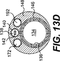
図13Bは、予拡張バルーンを備えたカテーテルの基端シャフトの断面を示すと共に、バルーン190の膨張と収縮とのための追加のルーメン192を示している。また、図13Cは、代替可能な実施形態として、予拡張バルーン190を備えると共にワイヤ制御カテーテル130の先端144のところ或いはその近くにセンタリングバルーン170を有するカテーテル130を示している。図13Cでは、予拡張バルーン190は、閉塞部10を通過するように前進せしめられたときであって狭窄部10を予拡張するために膨張せしめられる前の収縮されて折りたたまれた状態で略図的に示されている。図13Dは、予拡張バルーン190とセンタリングバルーン170とを備えたカテーテルの基端側のシャフトを示すと共に、予拡張バルーン190の膨張と収縮とに用いられるチューブ192とセンタリングバルーン170の膨張と収縮とに用いられるチューブ172とを示している。なお、この実施形態では、制御ワイヤルーメン138を介してセンタリングバルーン170を膨張させてもよいし、図示したように、センタリングバルーン170が膨張チューブ172を有していてもよい。
FIG. 13B shows a cross section of the proximal shaft of a catheter with a pre-dilatation balloon and an
ここで具体的に説明し、図17に示すように、ワイヤ制御カテーテル130は、該カテーテル130の基端部に取り付けられたハンドル構造50に接続されている。また、ハンドル構造50のベース部分52は、シャフト132の基端部に接続されている。また、案内ワイヤライナー136は、基端方向へ延び、案内ワイヤルーメン134を通した造影剤の供給とワイヤの交換とをしやすくするために、従来のルアー取付部品54を有する。造影剤を噴射できることは、図2Dに示したように、器具が真腔にアクセスしたか否かを評価するためには有用である。また、ハンドル構造のベース部分52には、ネジ56を介して回転前進具58が係合する。また、回転前進具58内では、制御ワイヤ142の基端部が通路60に係合する。ベース部分52に対する回転前進具58の回転は、制御ワイヤ142とカテーテルシャフト132との間で長手方向における相対的な動きを生じさせる。
Specifically described and shown in FIG. 17, the
本発明の別の形態として、ワイヤ制御カテーテルがフルレングスの案内ワイヤルーメンを備えていなくてもよい。その代わりに、ここで具体的に説明し、図11Aおよび図11Bに示すように、モノレール型のワイヤサポートカテーテル230が提供されてもよい。モノレール型のカテーテル230は、末端領域231aと基端領域231bとを有する。末端領域231aは、OTW型のカテーテル130用のシャフトと同様なシャフト232を有する。シャフト232は、案内ワイヤルーメン234を画成する(図9E)。案内ワイヤルーメン234は、カテーテル230の基端部よりもかなり末端側で終端する。カテーテル230の基端領域231bは、ルーメン238(図9E)を有し、このルーメン238内を屈曲可能な末端側先端部分244の関節のような曲がりを制御するための制御ワイヤ242が延びる。屈曲可能な末端側先端244は、図7に示したように、カテーテル130の屈曲可能な先端144に関連して上述にて説明したのと実質的に同じ構造を有する。また、屈曲可能な末端側先端244は、図8A〜図8Eに関連して上述にて説明したのと同じ或いは同様な関節構造を使用する。
As another form of the invention, the wire control catheter may not include a full-length guidewire lumen. Instead, a monorail
特に、案内ワイヤの交換中に案内ワイヤ214の先端を案内ワイヤルーメン234内へと案内しやすくするために、シャフト234の基端部に漏斗状の部分249が設けられてもよい。また、漏斗状の部分249内への案内ワイヤの蛍光透視視覚化を可能とするために、漏斗状の部分249が放射線不透過性であってもよい。使用時、案内ワイヤ214は、カテーテル230の基端領域231bに並んで延びる。このタイプのカテーテル構造は、案内ワイヤを「交換長さ」にまで延ばす必要なく、留置案内ワイヤ上をカテーテルが前進せしめられることを可能にする。
In particular, a funnel-shaped
ここで具体的に説明し、図9Bに示すように、カテーテル230のシャフト232は、案内ワイヤルーメン234を形成するように長手方向へと延びるライナー236を有する。捩れに対する剛性を提供するために、このライナー236をワイヤ網構造246が包囲している。ワイヤ網246は、好ましくは、例えば、ステンレス鋼からなる金属製リボンとして作製される金属製のものである。また、金属材料は、好ましくは、約0.0254mm×0.0762mm〜0.2032mm(約0.001インチ×0.003〜0.008インチ)の寸法のリボンである。また、堅さ特性および捩れに対する堅さ特性を変えるために、シャフトの長手方向に沿ってピックカウントを変えてもよい。
As specifically described herein and shown in FIG. 9B, the
また、制御ワイヤルーメン238をチューブ240が画成しており、このチューブ240は、好ましくは、網構造246の外側に配置されている。そして、この網構造は、ポリマー、例えば、ポリウレタン、ナイロン、Pebax、ポリイミド、PEEK、シリコーン、または、その他、同様な材料で覆われる。被包248は、カテーテル230のスムーズな外面を形成する。好ましくは、末端部から基端部までのシャフト232のフレキシビリティを変えるために、被包248の複数の部分が利用される。例えば、シャフトの最も末端側の部分が、デュロメートル硬度が小さいポリウレタンのような比較的フレキシブルなポリマーの被包を有し、より剛性のあるポリウレタンまたはPebaxへと移り変わり、そして、ナイロンに移り変わり、そして、ポリイミド被包に移り変わる。なお、シャフトの長手方向に沿った様々な位置におけるシャフトの堅さ特性や捩れに対する堅さ特性を調整するために、別の数の被包材料や別の組成の被包材料も考えられる。
The
モノレール型の制御カテーテル230の基端シャフト233は、好ましくは、ステンレス鋼からなる金属製のハイポチューブのような比較的堅いチューブから作製される。このような基端シャフトの構造は、捩れに対する比較的高い堅さを有する。図9Eは、モノレール型のカテーテル230の基端シャフト233と中間シャフト232との間の連結部を示している。基端シャフト233と「中間シャフト」との間の適切な接続部は、図11Aおよび図11Bに示したように、漏斗状の部分249を有する。
The
本発明の別の形態として、ワイヤサポートカテーテル230の屈曲可能な末端側先端244を血管壁12から離しつつ病変部10の基端部の中心に積極的に向けるために、カテーテル230がセンタリング要素を有していてもよい。ここで具体的に説明し、図12Cに示すように、センタリング要素は、例えば、ワイヤ制御カテーテル230の屈曲可能な末端側先端244近くの膨張可能なバルーン270である。これに代えて、図12Dに示したように、センタリングバルーン270をカテーテル230の屈曲可能な末端側先端244のところに配置してもよい。センタリングバルーン270は、図12A、図13C、および、図16に関連して上述にて説明したセンタリングバルーン170と実質的に同じように機能すると共に実質的に同じ構造を有する。
As another form of the present invention, the
これに代えて、図12Eに示したように、モノレール型の制御カテーテル230が、末端部に近いワイヤサポートカテーテル230の側から突出部分280として出現する突出ワイヤ282の形態のセンタリング要素を有していてもよい。センタリング突出ワイヤ282は、図12Bに関連して上述にて説明したセンタリング突出ワイヤ182と実質的に同じように機能すると共にそれと実質的に同じ構造を有する。さらに、カテーテル230が、図13A〜図13Dに関連して上述にて説明したのと同様の予拡張バルーンを有していてもよい。
Alternatively, as shown in FIG. 12E, the
モノレール型のワイヤサポートカテーテル230の典型的な使用においては、留置案内ワイヤ214に閉塞部10を通過させる努力が失敗に終わった後か、或いは、閉塞部10を通過させようとする前のいずれかに、留置案内ワイヤ214の基端部にカテーテル230が装着される。次いで、ワイヤ制御カテーテル230は、案内ワイヤ214の基端部を伝って装着されると共に、カテーテル230の末端側先端244が閉塞部10の近くに来るまで前進せしめられる。次いで、カテーテル230の末端側先端244と案内ワイヤ214とが閉塞部10の軸線に対して平行になるまで、上述したOTWカテーテル130と同様に、カテーテルシャフト230に対して基端方向へ制御ワイヤ242を引っ張ることによって先端244が湾曲するように或いは或る角度に曲がるように屈曲せしめられる。ここで、カテーテル先端244と案内ワイヤ214の末端領域とが放射線不透過性の材料から作製されている場合には、上述した工程中に案内ワイヤ214とカテーテル230とを視覚化するために蛍光透視を用いてもよい。また、留置案内ワイヤ214、または、留置案内ワイヤ214に代わる別のタイプの案内ワイヤが、ワイヤ制御カテーテル230の末端部まで閉塞部10を通って前進せしめられる。閉塞部10を成功裏に通過した後、ワイヤ制御カテーテル230が案内ワイヤ214から基端方向へ取り出される。ここでも、モノレールカテーテル230では、カテーテル230の案内ワイヤルーメン234が比較的短いので、案内ワイヤ214がその標準的な長さのままである。閉塞部10を拡張し或いは治療するためには、OTW型のワイヤサポートカテーテル130と同じく、従来の血管形成術やその他の望ましい外科処置が行われる。
In a typical use of a monorail
本発明の別の形態として、制御カテーテルに組み合わせて、スライドシースカテーテルが提供されてもよい。制御カテーテルは、例えば、図11Aおよび図11Bに関連して説明したようなモノレール型のカテーテル、または、図10に関連して説明したようなOTW型のカテーテルであり、上述したようなセンタリング要素(例えば、バルーン)および/または予拡張バルーンをさらに有する。この実施形態を説明するために、モノレール型のカテーテルを参照するが、この実施形態に別のタイプの制御カテーテルが用いられてもよい。 As another form of the present invention, a slide sheath catheter may be provided in combination with a control catheter. The control catheter is, for example, a monorail catheter as described in connection with FIGS. 11A and 11B or an OTW catheter as described in connection with FIG. For example, a balloon) and / or a pre-dilatation balloon. To describe this embodiment, reference is made to a monorail catheter, although other types of control catheters may be used in this embodiment.
ここで具体的に説明し、図14A〜図15に示すように、閉塞部の拡張を最小限に抑えつつ閉塞部を通過するための組合システムが提供される。図14Aに示したように、モノレールカテーテル330が提供される。また、直径が小さい薄くて前進可能なシースカテーテル320も提供される。また、図14Cは、「モノレール」型のシースを備えたスライドシースカテーテル320bを示しており、ここでは、カテーテル320bの末端部分だけが案内ワイヤルーメンを有する。シースカテーテル320は、ワイヤ制御カテーテル330の案内ワイヤルーメン334内にフィットする大きさであり、図15に示したように、案内ワイヤ314とワイヤ制御カテーテル330との間に環状に配置される。好ましい実施形態では、シースカテーテル320は、PTFE、または、HDPE、または、PEEKから作製される。好ましくは、シースカテーテル320は、約0.381mm(約0.015インチ)と約0.4318mm(約0.017インチ)との間の内径を有し、シースカテーテル320は、例えば、約0.0254mm〜約0.127mm(約0.001インチ〜約0.005インチ)の壁厚を有する。この実施形態では、ワイヤ制御カテーテル330の案内ワイヤルーメン334の内径は、上述した実施形態用のものよりも大きい。
As described in detail herein and illustrated in FIGS. 14A-15, a combined system is provided for passing through the closure while minimizing expansion of the closure. As shown in FIG. 14A, a
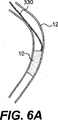
この組合システムは、図15に示したように、以下のように使用される。初めに、案内ワイヤ314とワイヤ制御カテーテル330とが、図6Aに示したように、病変部10に隣接して配置される。なお、これに代えて、センタリングされたアプローチがしやすいように、案内ワイヤ314とワイヤ制御カテーテル330とを図6Bに示したように配置してもよい。そして、例えば、ワイヤ制御カテーテル330の末端側端部344近くのその末端側端部のところにスライドシース320が「予め装着」されてあるか、或いは、後でスライドシース320を案内ワイヤ314に装着してワイヤ制御カテーテル330内に入れて上述したところに装着する。次に、図6Bに示した位置に対して残りの手順を説明する。図6Bに示したように配置されると、案内ワイヤ314とスライドシースカテーテル320とが、図6Cに示したように、病変部10へと前進せしめられる。次いで、案内ワイヤ314がスライドシースカテーテル320によって支持されると共に案内されつつ閉塞部10を通過するように前進せしめられる。シースカテーテル320は、図6Dに示した結果的な位置へと、案内ワイヤ314と共に前進せしめられてもよいし、案内ワイヤ314が病変部10を通って前進せしめられた後に前進せしめられてもよい。この時点で、例えば、案内ワイヤ314が取り出される。なお、これに代えて、必要であれば、冠動脈ツリーへと、より深く前進せしめるために、案内ワイヤを交換してもよい。
As shown in FIG. 15, this combination system is used as follows. Initially,
本発明のスライドシース実施形態320a、320bは、直径が非常に小さくて壁の薄いカテーテル320でもって完全閉塞部を通過することを可能とし、したがって、案内ワイヤ314自体によってなされるものを越えた病変部10の拡張を最小限に抑えることを可能とする。したがって、病変部10を通過する通り道が内膜下であるか或いは維管束外である場合には、こうした通過を確認する前に血液の漏れはほとんどない。
The
説明したワイヤ制御カテーテルの数々の構成要素の好ましい実施形態は、ステンレス鋼および白金合金のような金属を含むが、ここで説明したワイヤ制御カテーテルの殆どの構成要素または全ての構成要素を非金属製の構成要素から作製することも考えられる。このことは、上述したカテーテルを使用することが考えられる磁気共鳴映像法(MRI)が採用されるときには重要である。また、例えば、関節構造は、PEEKまたはポリイミドのような高強度ポリマーから作製される。また、制御ワイヤは、例えば、同じ材料、または、ナイロン、ポリエステル、超高モル重量ポリエチレン、Kevlar、および、ベクトランのような高強度ファイバーまたは複数の高強度ファイバーの束から作製される。 Preferred embodiments of the described wire control catheter components include metals such as stainless steel and platinum alloys, although most or all of the wire control catheter components described herein are made of non-metal. It is also conceivable to make it from the components. This is important when magnetic resonance imaging (MRI) is employed where it is possible to use the catheter described above. Also, for example, the joint structure is made from a high strength polymer such as PEEK or polyimide. The control wire is also made of the same material or a high strength fiber or bundle of high strength fibers such as nylon, polyester, ultra high molar weight polyethylene, Kevlar, and Vectran.
当業者には、本明細書や本明細書で開示した発明の実施を考慮すれば、本発明のその他の実施形態は明らかであろう。明細や例は例示だけものと考えるべきであり、本発明の真の範囲や精神は特許請求の範囲によって示される。 Other embodiments of the invention will be apparent to those skilled in the art from consideration of the specification and practice of the invention disclosed herein. The specification and examples are to be regarded as illustrative only, with the true scope and spirit of the invention being indicated by the appended claims.
Claims (12)
Applications Claiming Priority (2)
| Application Number | Priority Date | Filing Date | Title |
|---|---|---|---|
| US10/301,779 US20040102719A1 (en) | 2002-11-22 | 2002-11-22 | Guide wire control catheters for crossing occlusions and related methods of use |
| PCT/US2003/036783 WO2004047901A2 (en) | 2002-11-22 | 2003-11-18 | Guide wire control catheters for crossing occlusions and related methods of use |
Publications (3)
| Publication Number | Publication Date |
|---|---|
| JP2006507089A JP2006507089A (en) | 2006-03-02 |
| JP2006507089A5 JP2006507089A5 (en) | 2007-01-11 |
| JP4546250B2 true JP4546250B2 (en) | 2010-09-15 |
Family
ID=32324595
Family Applications (1)
| Application Number | Title | Priority Date | Filing Date |
|---|---|---|---|
| JP2004555478A Expired - Fee Related JP4546250B2 (en) | 2002-11-22 | 2003-11-18 | Guide wire control catheter for passing through an obstruction and method of use associated therewith |
Country Status (5)
| Country | Link |
|---|---|
| US (3) | US20040102719A1 (en) |
| EP (1) | EP1562666A2 (en) |
| JP (1) | JP4546250B2 (en) |
| AU (1) | AU2003291032A1 (en) |
| WO (1) | WO2004047901A2 (en) |
Families Citing this family (151)
| Publication number | Priority date | Publication date | Assignee | Title |
|---|---|---|---|---|
| US7071898B2 (en) * | 2002-07-18 | 2006-07-04 | Information Decision Technologies, Llc | Method for using a wireless motorized camera mount for tracking in augmented reality |
| DE10217868A1 (en) * | 2002-04-22 | 2003-10-30 | Jomed N V | Balloon Catheter |
| US7789770B1 (en) * | 2002-07-29 | 2010-09-07 | Laurence Hsiao-Cheng Li | Lightweight tensioning assembly |
| US7815580B2 (en) * | 2004-09-07 | 2010-10-19 | Stereotaxis, Inc. | Magnetic guidewire for lesion crossing |
| US8795315B2 (en) | 2004-10-06 | 2014-08-05 | Cook Medical Technologies Llc | Emboli capturing device having a coil and method for capturing emboli |
| JP4821947B2 (en) * | 2004-10-19 | 2011-11-24 | 朝日インテック株式会社 | Chemical injection device |
| US7402151B2 (en) * | 2004-12-17 | 2008-07-22 | Biocardia, Inc. | Steerable guide catheters and methods for their use |
| JP2006223338A (en) * | 2005-02-15 | 2006-08-31 | Humed Co Ltd | Catheter |
| US20060184105A1 (en) * | 2005-02-15 | 2006-08-17 | Townsend Gregory L | Thin wall catheter and method of placing same |
| US8945169B2 (en) | 2005-03-15 | 2015-02-03 | Cook Medical Technologies Llc | Embolic protection device |
| US8221446B2 (en) | 2005-03-15 | 2012-07-17 | Cook Medical Technologies | Embolic protection device |
| US20090118612A1 (en) * | 2005-05-06 | 2009-05-07 | Sorin Grunwald | Apparatus and Method for Vascular Access |
| JP4972639B2 (en) * | 2005-05-06 | 2012-07-11 | バソノバ・インコーポレイテッド | Method and apparatus for guiding and positioning an intravascular device |
| US8267872B2 (en) * | 2005-07-07 | 2012-09-18 | St. Jude Medical, Cardiology Division, Inc. | Steerable guide wire with torsionally stable tip |
| US20070185415A1 (en) * | 2005-07-07 | 2007-08-09 | Ressemann Thomas V | Steerable guide wire with torsionally stable tip |
| US8187298B2 (en) | 2005-08-04 | 2012-05-29 | Cook Medical Technologies Llc | Embolic protection device having inflatable frame |
| US7938819B2 (en) | 2005-09-12 | 2011-05-10 | Bridgepoint Medical, Inc. | Endovascular devices and methods |
| EP3650074B1 (en) | 2005-09-12 | 2023-10-25 | Boston Scientific Scimed, Inc. | Endovascular devices |
| US11020141B2 (en) | 2005-09-12 | 2021-06-01 | Bridgepoint Medical, Inc. | Endovascular devices and methods |
| US7918870B2 (en) | 2005-09-12 | 2011-04-05 | Bridgepoint Medical, Inc. | Endovascular devices and methods |
| US8083727B2 (en) | 2005-09-12 | 2011-12-27 | Bridgepoint Medical, Inc. | Endovascular devices and methods for exploiting intramural space |
| US8377092B2 (en) * | 2005-09-16 | 2013-02-19 | Cook Medical Technologies Llc | Embolic protection device |
| JP4868387B2 (en) * | 2005-09-21 | 2012-02-01 | 朝日インテック株式会社 | Chemical injection device |
| US8632562B2 (en) | 2005-10-03 | 2014-01-21 | Cook Medical Technologies Llc | Embolic protection device |
| US8182508B2 (en) | 2005-10-04 | 2012-05-22 | Cook Medical Technologies Llc | Embolic protection device |
| US8252017B2 (en) | 2005-10-18 | 2012-08-28 | Cook Medical Technologies Llc | Invertible filter for embolic protection |
| US8216269B2 (en) * | 2005-11-02 | 2012-07-10 | Cook Medical Technologies Llc | Embolic protection device having reduced profile |
| US8192477B2 (en) * | 2005-11-14 | 2012-06-05 | Boston Scientific Scimed, Inc. | Twisting bifurcation delivery system |
| US8152831B2 (en) | 2005-11-17 | 2012-04-10 | Cook Medical Technologies Llc | Foam embolic protection device |
| US7892186B2 (en) * | 2005-12-09 | 2011-02-22 | Heraeus Materials S.A. | Handle and articulator system and method |
| US8048032B2 (en) | 2006-05-03 | 2011-11-01 | Vascular Solutions, Inc. | Coaxial guide catheter for interventional cardiology procedures |
| US7909789B2 (en) | 2006-06-26 | 2011-03-22 | Sight Sciences, Inc. | Intraocular implants and methods and kits therefor |
| US7674253B2 (en) * | 2006-08-18 | 2010-03-09 | Kensey Nash Corporation | Catheter for conducting a procedure within a lumen, duct or organ of a living being |
| US20080071307A1 (en) | 2006-09-19 | 2008-03-20 | Cook Incorporated | Apparatus and methods for in situ embolic protection |
| US10413284B2 (en) | 2006-11-07 | 2019-09-17 | Corvia Medical, Inc. | Atrial pressure regulation with control, sensing, monitoring and therapy delivery |
| US9232997B2 (en) | 2006-11-07 | 2016-01-12 | Corvia Medical, Inc. | Devices and methods for retrievable intra-atrial implants |
| AU2007317191B2 (en) | 2006-11-07 | 2014-02-20 | Corvia Medical, Inc. | Devices and methods for the treatment of heart failure |
| US20110257723A1 (en) | 2006-11-07 | 2011-10-20 | Dc Devices, Inc. | Devices and methods for coronary sinus pressure relief |
| US8460372B2 (en) | 2006-11-07 | 2013-06-11 | Dc Devices, Inc. | Prosthesis for reducing intra-cardiac pressure having an embolic filter |
| US8740962B2 (en) * | 2006-11-07 | 2014-06-03 | Dc Devices, Inc. | Prosthesis for retrieval and deployment |
| US9060802B2 (en) | 2006-11-21 | 2015-06-23 | Bridgepoint Medical, Inc. | Endovascular devices and methods for exploiting intramural space |
| US10888354B2 (en) * | 2006-11-21 | 2021-01-12 | Bridgepoint Medical, Inc. | Endovascular devices and methods for exploiting intramural space |
| US11298511B2 (en) | 2006-11-21 | 2022-04-12 | Bridgepoint Medical, Inc. | Endovascular devices and methods for exploiting intramural space |
| US20080195140A1 (en) * | 2006-12-08 | 2008-08-14 | Cook Incorporated | Delivery system for an embolic protection device |
| WO2008085167A1 (en) * | 2007-01-10 | 2008-07-17 | St. Jude Medical, Cardiology Division, Inc. | Steerable guide wire with torsionally stable tip |
| US9901434B2 (en) | 2007-02-27 | 2018-02-27 | Cook Medical Technologies Llc | Embolic protection device including a Z-stent waist band |
| JP5564416B2 (en) | 2007-03-29 | 2014-07-30 | ボストン サイエンティフィック リミテッド | Lumen reentry device |
| US9387308B2 (en) | 2007-04-23 | 2016-07-12 | Cardioguidance Biomedical, Llc | Guidewire with adjustable stiffness |
| JP2010524631A (en) * | 2007-04-23 | 2010-07-22 | インターヴェンショナル アンド サージカル イノヴェイションズ リミテッド ライアビリティ カンパニー | Guidewire with adjustable stiffness |
| US9358142B2 (en) * | 2007-04-24 | 2016-06-07 | W. L. Gore & Associates, Inc. | Catheter having guidewire channel |
| US8273115B2 (en) | 2007-04-24 | 2012-09-25 | W. L. Gore & Associates, Inc. | Side branched endoluminal prostheses and methods of delivery thereof |
| EP2170162B1 (en) | 2007-06-26 | 2017-08-23 | Vasonova, Inc. | Apparatus for endovascular device guiding and positioning using physiological parameters |
| US8419748B2 (en) | 2007-09-14 | 2013-04-16 | Cook Medical Technologies Llc | Helical thrombus removal device |
| US8252018B2 (en) | 2007-09-14 | 2012-08-28 | Cook Medical Technologies Llc | Helical embolic protection device |
| US9138307B2 (en) | 2007-09-14 | 2015-09-22 | Cook Medical Technologies Llc | Expandable device for treatment of a stricture in a body vessel |
| EP2211968B1 (en) | 2007-10-22 | 2020-02-26 | Bridgepoint Medical, Inc. | Devices for crossing chronic total occlusions |
| US8876704B2 (en) * | 2008-01-14 | 2014-11-04 | Boston Scientific Scimed, Inc. | Medical device |
| WO2009100129A2 (en) | 2008-02-05 | 2009-08-13 | Chad John Kugler | Crossing occlusions in blood vessels |
| US8337425B2 (en) | 2008-02-05 | 2012-12-25 | Bridgepoint Medical, Inc. | Endovascular device with a tissue piercing distal probe and associated methods |
| JP5513486B2 (en) | 2008-04-28 | 2014-06-04 | ブリッジポイント、メディカル、インコーポレイテッド | Method and apparatus for traversing a vessel occlusion |
| US20100016937A1 (en) * | 2008-07-18 | 2010-01-21 | Yousef Alkhatib | Twisting Bifurcation Delivery System |
| US20100049137A1 (en) * | 2008-08-20 | 2010-02-25 | Cook Incorporated | Device for Crossing Occlusions and Method of Use Thereof |
| US8162891B2 (en) * | 2008-11-26 | 2012-04-24 | Revascular Therapeutics, Inc. | Delivery and exchange catheter for storing guidewire |
| EP2370237B1 (en) | 2008-12-08 | 2015-12-02 | Jeff Christian | Micro-cutting machine for forming cuts in products |
| US20220296850A1 (en) * | 2008-12-08 | 2022-09-22 | Scientia Vascular, Inc. | Micro-fabricated intravascular devices having varying diameters |
| US11406791B2 (en) * | 2009-04-03 | 2022-08-09 | Scientia Vascular, Inc. | Micro-fabricated guidewire devices having varying diameters |
| US10363389B2 (en) * | 2009-04-03 | 2019-07-30 | Scientia Vascular, Llc | Micro-fabricated guidewire devices having varying diameters |
| US8388644B2 (en) | 2008-12-29 | 2013-03-05 | Cook Medical Technologies Llc | Embolic protection device and method of use |
| US20100191150A1 (en) | 2009-01-27 | 2010-07-29 | Palme Jr Robert A | Guidewire |
| US9616195B2 (en) * | 2009-04-03 | 2017-04-11 | Scientia Vascular, Llc | Micro-fabricated catheter devices having varying diameters |
| US9067332B2 (en) * | 2009-04-03 | 2015-06-30 | Scientia Vascular, Llc | Micro-fabricated catheter devices formed with hybrid materials |
| US20100256603A1 (en) * | 2009-04-03 | 2010-10-07 | Scientia Vascular, Llc | Micro-fabricated Catheter Devices Formed Having Elastomeric Fill Compositions |
| US9067333B2 (en) | 2009-04-03 | 2015-06-30 | Scientia Vascular, Llc | Micro-fabricated guidewire devices having elastomeric fill compositions |
| US9950137B2 (en) * | 2009-04-03 | 2018-04-24 | Scientia Vascular, Llc | Micro-fabricated guidewire devices formed with hybrid materials |
| US20100292565A1 (en) * | 2009-05-18 | 2010-11-18 | Andreas Meyer | Medical imaging medical device navigation from at least two 2d projections from different angles |
| WO2010151698A2 (en) * | 2009-06-24 | 2010-12-29 | Shifamed, Llc | Steerable medical delivery devices and methods of use |
| WO2011025855A2 (en) | 2009-08-28 | 2011-03-03 | Si Therapies Ltd. | Inverted balloon neck on catheter |
| US9757107B2 (en) | 2009-09-04 | 2017-09-12 | Corvia Medical, Inc. | Methods and devices for intra-atrial shunts having adjustable sizes |
| US9642993B2 (en) | 2011-12-22 | 2017-05-09 | Corvia Medical, Inc. | Methods and devices for intra-atrial shunts having selectable flow rates |
| WO2011068540A1 (en) | 2009-12-03 | 2011-06-09 | Therix Medical Development, Ltd. | Central venous access system |
| US8597314B2 (en) * | 2009-12-29 | 2013-12-03 | Cook Medical Technologies Llc | Helically advancing constriction crossing mechanism and wire guide positioning method for performing percutaneous vascular procedures |
| AU2011210741B2 (en) | 2010-01-29 | 2013-08-15 | Corvia Medical, Inc. | Devices and methods for reducing venous pressure |
| US20110202038A1 (en) * | 2010-02-12 | 2011-08-18 | Sukhjit Gill | Guidewire positioning device |
| EP2566405A4 (en) * | 2010-05-04 | 2014-07-30 | Samuel Shiber | Rotary catheter for removing obstructions from bodily vessels |
| WO2013025697A1 (en) | 2011-08-17 | 2013-02-21 | Samuel Shiber | Adaptive rotary catheter for opening obstructed bodily vessels |
| US20150094733A1 (en) | 2010-05-04 | 2015-04-02 | Samuel Shiber | Rotary catheter drive unit containing seal-sets |
| US9907567B2 (en) | 2010-05-04 | 2018-03-06 | Samuel Shiber | Mechanical — pharmaceutical system for opening obstructed bodily vessels |
| US10952764B2 (en) | 2010-05-04 | 2021-03-23 | Samuel Shiber | Rotary catheter drive unit containing seal-sets |
| US20110319905A1 (en) | 2010-06-23 | 2011-12-29 | Palme Robert A | Multiple function vascular device |
| EP2637568B1 (en) | 2010-11-08 | 2017-04-12 | Vasonova, Inc. | Endovascular navigation system |
| CN103635226B (en) | 2011-02-10 | 2017-06-30 | 可维亚媒体公司 | Device for setting up and keeping intra-atrial pressure power release aperture |
| US8685003B2 (en) | 2011-03-29 | 2014-04-01 | Covidien Lp | Dual cable triangulation mechanism |
| US20130116705A1 (en) | 2011-05-03 | 2013-05-09 | Amr Salahieh | Steerable Delivery Sheaths |
| US8845517B2 (en) | 2011-06-27 | 2014-09-30 | Covidien Lp | Triangulation mechanism for a minimally invasive surgical device |
| US9095370B2 (en) | 2011-06-29 | 2015-08-04 | Cordis Corporation | System and method for dilating and adjusting flexibility in a guiding device |
| WO2013043592A1 (en) | 2011-09-19 | 2013-03-28 | Boston Scientific Scimed, Inc. | Subintimal re-entry catheter and retrograde recanalization |
| US9302084B2 (en) | 2011-12-09 | 2016-04-05 | Boston Scientific Scimed, Inc. | Subintimal recanalization with bio-absorbable stent |
| US9005155B2 (en) | 2012-02-03 | 2015-04-14 | Dc Devices, Inc. | Devices and methods for treating heart failure |
| CA2863920C (en) * | 2012-02-09 | 2020-02-25 | Therix Medical Development, Ltd. | Occlusion access system |
| US10092726B2 (en) * | 2012-02-09 | 2018-10-09 | Bluegrass Vascular Technologies, Inc. | Occlusion access system |
| ES2961369T3 (en) | 2012-03-20 | 2024-03-11 | Sight Sciences Inc | Eye delivery systems |
| US8961550B2 (en) | 2012-04-17 | 2015-02-24 | Indian Wells Medical, Inc. | Steerable endoluminal punch |
| US10588611B2 (en) | 2012-04-19 | 2020-03-17 | Corvia Medical Inc. | Implant retention attachment and method of use |
| JP6185048B2 (en) | 2012-05-07 | 2017-08-23 | バソノバ・インコーポレイテッドVasonova, Inc. | System and method for detection of superior vena cava area and vena cava atrial junction |
| JP6085674B2 (en) | 2012-05-24 | 2017-02-22 | ボストン サイエンティフィック サイムド,インコーポレイテッドBoston Scientific Scimed,Inc. | Subintimal re-entry device |
| US9649480B2 (en) | 2012-07-06 | 2017-05-16 | Corvia Medical, Inc. | Devices and methods of treating or ameliorating diastolic heart failure through pulmonary valve intervention |
| US9174032B2 (en) | 2012-07-13 | 2015-11-03 | Boston Scientific Scimed, Inc. | Subintimal reentry system |
| US9456842B2 (en) | 2012-07-13 | 2016-10-04 | Boston Scientific Scimed, Inc. | Wire-guided recanalization system |
| WO2014013564A1 (en) * | 2012-07-18 | 2014-01-23 | テルモ株式会社 | Medical treatment instrument |
| US8986225B2 (en) | 2012-08-02 | 2015-03-24 | Covidien Lp | Guidewire |
| JP5780526B2 (en) * | 2012-12-27 | 2015-09-16 | 朝日インテック株式会社 | Guide wire |
| US9775636B2 (en) | 2013-03-12 | 2017-10-03 | Corvia Medical, Inc. | Devices, systems, and methods for treating heart failure |
| CN105228538B (en) | 2013-03-14 | 2018-04-24 | 波士顿科学国际有限公司 | Reentry catheter under inner membrance with controlled shape sacculus |
| EP2967601B1 (en) | 2013-03-14 | 2017-11-29 | Boston Scientific Scimed, Inc. | Systems and apparatus for treating blood vessels |
| JP6629183B2 (en) | 2013-03-15 | 2020-01-15 | デピュイ・シンセス・プロダクツ・インコーポレイテッド | Frame calibration of white balance and fixed pattern noise using a distal cap |
| EP3046508B1 (en) | 2013-09-19 | 2022-12-14 | New Karyna, LLC | System for deploying a luminal prosthesis over a carina |
| US10675450B2 (en) | 2014-03-12 | 2020-06-09 | Corvia Medical, Inc. | Devices and methods for treating heart failure |
| US10098650B2 (en) | 2014-06-09 | 2018-10-16 | Boston Scientific Scimed, Inc. | Systems and methods for treating atherosclerotic plaque |
| EP3171786B1 (en) | 2014-07-23 | 2020-05-13 | Corvia Medical, Inc. | Devices for treating heart failure |
| US9636477B2 (en) * | 2014-10-09 | 2017-05-02 | Vascular Solutions, Inc. | Catheter |
| WO2016149272A1 (en) | 2015-03-19 | 2016-09-22 | Boston Scientific Scimed, Inc. | Subintimal re-entry balloon catheter |
| CA2979884A1 (en) | 2015-03-27 | 2016-10-06 | Shifamed Holdings, Llc | Steerable medical devices, systems, and methods of use |
| US10299958B2 (en) | 2015-03-31 | 2019-05-28 | Sight Sciences, Inc. | Ocular delivery systems and methods |
| EP3285849A4 (en) | 2015-04-24 | 2018-12-26 | Shifamed Holdings, LLC | Steerable medical devices, systems, and methods of use |
| EP3302674B1 (en) | 2015-05-26 | 2019-01-30 | Teleflex Innovations S.à.r.l. | Guidewire fixation |
| US20170000519A1 (en) * | 2015-06-30 | 2017-01-05 | Furqan Tejani | Interventional wire capture device and methods of use |
| US10525256B2 (en) * | 2015-07-29 | 2020-01-07 | Medtronic, Inc. | Interventional medical systems, catheters, and methods |
| CN108366715A (en) | 2015-11-09 | 2018-08-03 | 施菲姆德控股有限责任公司 | Steering assembly and application method for medical treatment device |
| AU2017227088B2 (en) | 2016-02-29 | 2022-01-06 | Merit Medical Systems, Inc. | Catheter systems, kits, and methods for gaining access to a vessel |
| KR101839108B1 (en) * | 2016-04-29 | 2018-04-26 | 서울대학교병원 | Apparatus for cto lesion |
| WO2017205662A1 (en) * | 2016-05-26 | 2017-11-30 | Boston Scientific Scimed, Inc. | Articulating devices |
| US11207502B2 (en) | 2016-07-18 | 2021-12-28 | Scientia Vascular, Llc | Guidewire devices having shapeable tips and bypass cuts |
| US11052228B2 (en) | 2016-07-18 | 2021-07-06 | Scientia Vascular, Llc | Guidewire devices having shapeable tips and bypass cuts |
| US10821268B2 (en) | 2016-09-14 | 2020-11-03 | Scientia Vascular, Llc | Integrated coil vascular devices |
| EP3888691A1 (en) * | 2016-11-14 | 2021-10-06 | Hangzhou Dac Biotech Co., Ltd. | Conjugation linkers, cell binding molecule-drug conjugates containing the likers, methods of making and uses such conjugates with the linkers |
| US10751514B2 (en) | 2016-12-09 | 2020-08-25 | Teleflex Life Sciences Limited | Guide extension catheter |
| US11452541B2 (en) | 2016-12-22 | 2022-09-27 | Scientia Vascular, Inc. | Intravascular device having a selectively deflectable tip |
| US10085766B1 (en) | 2017-03-31 | 2018-10-02 | Jihad A. Mustapha | Chronic total occlusion crossing devices and methods |
| ES2869148T3 (en) | 2017-05-26 | 2021-10-25 | Scientia Vascular Llc | Microfabricated medical device with a non-helical cutting arrangement |
| WO2019006439A1 (en) * | 2017-06-30 | 2019-01-03 | Reliantheart, Inc. | Vascular graft protector |
| US10238834B2 (en) | 2017-08-25 | 2019-03-26 | Teleflex Innovations S.À.R.L. | Catheter |
| WO2019109063A2 (en) | 2017-12-03 | 2019-06-06 | Paul Ram H Jr | Mri compatible interventional wireguide |
| US11305095B2 (en) | 2018-02-22 | 2022-04-19 | Scientia Vascular, Llc | Microfabricated catheter having an intermediate preferred bending section |
| KR102254022B1 (en) * | 2018-09-06 | 2021-05-20 | 한국과학기술원 | Steerable guidewire and method for manufacturing steerable suidewire, steerable catheter and method for manufacturing steerable catheter |
| WO2020112293A1 (en) | 2018-11-27 | 2020-06-04 | Teleflex Life Sciences Limited | Guide extension catheter |
| WO2020131227A1 (en) | 2018-12-19 | 2020-06-25 | Teleflex Life Sciences Limited | Guide extension catheter |
| WO2020146035A1 (en) | 2019-01-07 | 2020-07-16 | Teleflex Life Sciences Limited | Guide extension catheter |
| US11504270B1 (en) | 2019-09-27 | 2022-11-22 | Sight Sciences, Inc. | Ocular delivery systems and methods |
| US11813420B2 (en) | 2020-03-25 | 2023-11-14 | Medtronic Vascular, Inc. | Balloon catheter |
| US20220016394A1 (en) * | 2020-07-16 | 2022-01-20 | Canon U.S.A., Inc. | Medical Apparatus and Method of Use Thereof |
| CN115414574B (en) * | 2022-08-17 | 2023-04-07 | 广东博迈医疗科技股份有限公司 | Catheter tip, balloon catheter and blood vessel intervention device |
Family Cites Families (82)
| Publication number | Priority date | Publication date | Assignee | Title |
|---|---|---|---|---|
| US2688329A (en) * | 1953-03-19 | 1954-09-07 | American Cystoscope Makers Inc | Catheter |
| US4353358A (en) * | 1980-08-28 | 1982-10-12 | Emerson Reynolds L | Sigmoidoscope |
| US4516972A (en) * | 1982-01-28 | 1985-05-14 | Advanced Cardiovascular Systems, Inc. | Guiding catheter and method of manufacture |
| US4586923A (en) * | 1984-06-25 | 1986-05-06 | Cordis Corporation | Curving tip catheter |
| US4960411A (en) * | 1984-09-18 | 1990-10-02 | Medtronic Versaflex, Inc. | Low profile sterrable soft-tip catheter |
| US5102390A (en) * | 1985-05-02 | 1992-04-07 | C. R. Bard, Inc. | Microdilatation probe and system for performing angioplasty in highly stenosed blood vessels |
| US5449343A (en) * | 1985-07-30 | 1995-09-12 | Advanced Cardiovascular Systems, Inc. | Steerable dilatation catheter |
| US4723936A (en) * | 1986-07-22 | 1988-02-09 | Versaflex Delivery Systems Inc. | Steerable catheter |
| US4719924A (en) * | 1986-09-09 | 1988-01-19 | C. R. Bard, Inc. | Small diameter steerable guidewire with adjustable tip |
| US4757827A (en) * | 1987-02-17 | 1988-07-19 | Versaflex Delivery Systems Inc. | Steerable guidewire with deflectable tip |
| US4793359A (en) * | 1987-04-24 | 1988-12-27 | Gv Medical, Inc. | Centering balloon structure for transluminal angioplasty catheter |
| US5154705A (en) * | 1987-09-30 | 1992-10-13 | Lake Region Manufacturing Co., Inc. | Hollow lumen cable apparatus |
| US6210395B1 (en) * | 1987-09-30 | 2001-04-03 | Lake Region Mfg., Inc. | Hollow lumen cable apparatus |
| US5165421A (en) * | 1987-09-30 | 1992-11-24 | Lake Region Manufacturing Co., Inc. | Hollow lumen cable apparatus |
| US4838268A (en) * | 1988-03-07 | 1989-06-13 | Scimed Life Systems, Inc. | Non-over-the wire balloon catheter |
| US4951677A (en) * | 1988-03-21 | 1990-08-28 | Prutech Research And Development Partnership Ii | Acoustic imaging catheter and the like |
| US4932419A (en) * | 1988-03-21 | 1990-06-12 | Boston Scientific Corporation | Multi-filar, cross-wound coil for medical devices |
| US4998923A (en) * | 1988-08-11 | 1991-03-12 | Advanced Cardiovascular Systems, Inc. | Steerable dilatation catheter |
| US5030204A (en) * | 1988-09-28 | 1991-07-09 | Advanced Cardiovascular Systems, Inc. | Guiding catheter with controllable distal tip |
| US4898577A (en) * | 1988-09-28 | 1990-02-06 | Advanced Cardiovascular Systems, Inc. | Guiding cathether with controllable distal tip |
| US5037391A (en) * | 1989-01-09 | 1991-08-06 | Pilot Cardiovascular Systems, Inc. | Steerable angioplasty device |
| US4911148A (en) * | 1989-03-14 | 1990-03-27 | Intramed Laboratories, Inc. | Deflectable-end endoscope with detachable flexible shaft assembly |
| US5002041A (en) * | 1989-05-12 | 1991-03-26 | Kabushiki Kaisha Machida Seisakusho | Bending device and flexible tube structure |
| US5131407A (en) * | 1989-12-01 | 1992-07-21 | C. R. Bard, Inc. | Guidewire with tracking member and catheter exchange system |
| US4983165A (en) * | 1990-01-23 | 1991-01-08 | Loiterman David A | Guidance system for vascular catheter or the like |
| US5060660A (en) * | 1990-02-28 | 1991-10-29 | C. R. Bard, Inc. | Steerable extendable guidewire with adjustable tip |
| WO1991013649A1 (en) * | 1990-03-16 | 1991-09-19 | Medtronic, Inc. | Dilatation catheter |
| US5158548A (en) * | 1990-04-25 | 1992-10-27 | Advanced Cardiovascular Systems, Inc. | Method and system for stent delivery |
| US5997497A (en) * | 1991-01-11 | 1999-12-07 | Advanced Cardiovascular Systems | Ultrasound catheter having integrated drug delivery system and methods of using same |
| US5409453A (en) * | 1992-08-12 | 1995-04-25 | Vidamed, Inc. | Steerable medical probe with stylets |
| US5329923A (en) * | 1991-02-15 | 1994-07-19 | Lundquist Ingemar H | Torquable catheter |
| US5315996A (en) * | 1991-02-15 | 1994-05-31 | Lundquist Ingemar H | Torquable catheter and method |
| US5228441A (en) * | 1991-02-15 | 1993-07-20 | Lundquist Ingemar H | Torquable catheter and method |
| US5290247A (en) * | 1991-05-21 | 1994-03-01 | C. R. Bard, Inc. | Intracoronary exchange apparatus and method |
| US6902555B2 (en) * | 1991-07-15 | 2005-06-07 | Larry D. Paskar | Shapeable catheter |
| US6866650B2 (en) * | 1991-07-16 | 2005-03-15 | Heartport, Inc. | System for cardiac procedures |
| US5380304A (en) * | 1991-08-07 | 1995-01-10 | Cook Incorporated | Flexible, kink-resistant, introducer sheath and method of manufacture |
| US5269757A (en) * | 1991-12-02 | 1993-12-14 | C. R. Bard, Inc. | Catheter with integral steerable guidewire having linear to rotary movement |
| US5419767A (en) * | 1992-01-07 | 1995-05-30 | Thapliyal And Eggers Partners | Methods and apparatus for advancing catheters through severely occluded body lumens |
| CA2117386A1 (en) * | 1992-01-09 | 1993-07-22 | Motasim M. Sirhan | Guidewire replacement device |
| US5281200A (en) * | 1992-12-08 | 1994-01-25 | Cordis Corporation | Multiple component balloon catheter system and stenosis treatment procedure |
| US5669926A (en) * | 1993-01-25 | 1997-09-23 | Aust & Taylor Medical Corporation | Surgical instrument |
| US5378234A (en) * | 1993-03-15 | 1995-01-03 | Pilot Cardiovascular Systems, Inc. | Coil polymer composite |
| DE4320962C2 (en) * | 1993-06-24 | 1997-04-17 | Osypka Peter | Catheter made of a flexible plastic tube |
| US5722972A (en) * | 1993-08-12 | 1998-03-03 | Power; John A. | Method and apparatus for ablation of atherosclerotic blockage |
| US5628761A (en) * | 1994-07-08 | 1997-05-13 | Rizik; David G. | Guide wire passage creation device |
| CA2218105A1 (en) * | 1995-03-30 | 1996-10-03 | Heartport, Inc. | Endovascular cardiac venting catheter and method |
| US6068623A (en) * | 1997-03-06 | 2000-05-30 | Percusurge, Inc. | Hollow medical wires and methods of constructing same |
| US6077295A (en) * | 1996-07-15 | 2000-06-20 | Advanced Cardiovascular Systems, Inc. | Self-expanding stent delivery system |
| US5827201A (en) * | 1996-07-26 | 1998-10-27 | Target Therapeutics, Inc. | Micro-braided guidewire |
| US6606515B1 (en) * | 1996-09-13 | 2003-08-12 | Scimed Life Systems, Inc. | Guide wire insertion and re-insertion tools and methods of use |
| US6010449A (en) * | 1997-02-28 | 2000-01-04 | Lumend, Inc. | Intravascular catheter system for treating a vascular occlusion |
| US6554795B2 (en) * | 1997-03-06 | 2003-04-29 | Medtronic Ave, Inc. | Balloon catheter and method of manufacture |
| US6190332B1 (en) * | 1998-02-19 | 2001-02-20 | Percusurge, Inc. | Core wire with shapeable tip |
| US6355016B1 (en) * | 1997-03-06 | 2002-03-12 | Medtronic Percusurge, Inc. | Catheter core wire |
| US6152912A (en) * | 1997-06-10 | 2000-11-28 | Target Therapeutics, Inc. | Optimized high performance spiral-wound vascular catheter |
| US5851212A (en) * | 1997-06-11 | 1998-12-22 | Endius Incorporated | Surgical instrument |
| JPH11221229A (en) * | 1997-09-24 | 1999-08-17 | Eclipse Surgical Technol Inc | Catheter |
| US6013085A (en) * | 1997-11-07 | 2000-01-11 | Howard; John | Method for treating stenosis of the carotid artery |
| US6156046A (en) * | 1997-11-07 | 2000-12-05 | Prolifix Medical, Inc. | Methods and systems for treating obstructions in a body lumen |
| US5935108A (en) * | 1997-11-14 | 1999-08-10 | Reflow, Inc. | Recanalization apparatus and devices for use therein and method |
| US6110164A (en) * | 1997-12-05 | 2000-08-29 | Intratherapeutics, Inc. | Guideless catheter segment |
| US6228072B1 (en) * | 1998-02-19 | 2001-05-08 | Percusurge, Inc. | Shaft for medical catheters |
| US6746422B1 (en) * | 2000-08-23 | 2004-06-08 | Norborn Medical, Inc. | Steerable support system with external ribs/slots that taper |
| US6048339A (en) * | 1998-06-29 | 2000-04-11 | Endius Incorporated | Flexible surgical instruments with suction |
| US7972323B1 (en) * | 1998-10-02 | 2011-07-05 | Boston Scientific Scimed, Inc. | Steerable device for introducing diagnostic and therapeutic apparatus into the body |
| US6210408B1 (en) * | 1999-02-24 | 2001-04-03 | Scimed Life Systems, Inc. | Guide wire system for RF recanalization of vascular blockages |
| US6409723B1 (en) * | 1999-04-02 | 2002-06-25 | Stuart D. Edwards | Treating body tissue by applying energy and substances |
| EP1196212A2 (en) * | 1999-06-15 | 2002-04-17 | Cryocath Technologies inc. | Steerable catheter |
| AU2632001A (en) * | 2000-01-06 | 2001-07-16 | Raymond L. Bedell | Steerable fiberoptic epidural balloon catheter and scope |
| US6394976B1 (en) * | 2000-01-31 | 2002-05-28 | Intraluminal Therapeutics, Inc. | Catheter for controlling the advancement of a guide wire |
| CA2403385C (en) * | 2000-03-20 | 2009-03-10 | Unicoil International Pty Ltd. | Hose bending clamp |
| US6491681B1 (en) * | 2000-04-06 | 2002-12-10 | Scimed Life Systems, Inc. | Handle for use with steerable device for introducing diagnostic and therapeutic elements into the body |
| US6533753B1 (en) * | 2000-04-07 | 2003-03-18 | Philip Haarstad | Apparatus and method for the treatment of an occluded lumen |
| US6482221B1 (en) * | 2000-08-21 | 2002-11-19 | Counter Clockwise, Inc. | Manipulatable delivery catheter for occlusive devices (II) |
| US6569129B1 (en) * | 2000-09-13 | 2003-05-27 | Mayo Foundation For Medical Education And Research | Biological revascularization |
| US6511471B2 (en) * | 2000-12-22 | 2003-01-28 | Biocardia, Inc. | Drug delivery catheters that attach to tissue and methods for their use |
| US6428552B1 (en) * | 2001-01-22 | 2002-08-06 | Lumend, Inc. | Method and apparatus for crossing intravascular occlusions |
| US6623448B2 (en) * | 2001-03-30 | 2003-09-23 | Advanced Cardiovascular Systems, Inc. | Steerable drug delivery device |
| US20030023261A1 (en) * | 2001-07-30 | 2003-01-30 | Scimed Life Systems Inc. | Chronic total occlusion device with variable stiffness shaft |
| US7840261B2 (en) * | 2002-06-05 | 2010-11-23 | Biocardia, Inc. | Catheter systems and methods for placing bi-ventricular pacing leads |
| US6945956B2 (en) * | 2002-12-23 | 2005-09-20 | Medtronic, Inc. | Steerable catheter |
-
2002
- 2002-11-22 US US10/301,779 patent/US20040102719A1/en not_active Abandoned
-
2003
- 2003-11-18 JP JP2004555478A patent/JP4546250B2/en not_active Expired - Fee Related
- 2003-11-18 WO PCT/US2003/036783 patent/WO2004047901A2/en active Application Filing
- 2003-11-18 AU AU2003291032A patent/AU2003291032A1/en not_active Abandoned
- 2003-11-18 EP EP03783618A patent/EP1562666A2/en not_active Withdrawn
-
2008
- 2008-09-09 US US12/207,391 patent/US20090005755A1/en not_active Abandoned
-
2015
- 2015-02-11 US US14/619,730 patent/US20150151081A1/en not_active Abandoned
Also Published As
| Publication number | Publication date |
|---|---|
| EP1562666A2 (en) | 2005-08-17 |
| US20040102719A1 (en) | 2004-05-27 |
| AU2003291032A1 (en) | 2004-06-18 |
| WO2004047901A2 (en) | 2004-06-10 |
| US20090005755A1 (en) | 2009-01-01 |
| AU2003291032A8 (en) | 2004-06-18 |
| JP2006507089A (en) | 2006-03-02 |
| WO2004047901A3 (en) | 2004-09-23 |
| US20150151081A1 (en) | 2015-06-04 |
Similar Documents
| Publication | Publication Date | Title |
|---|---|---|
| JP4546250B2 (en) | Guide wire control catheter for passing through an obstruction and method of use associated therewith | |
| CN115484900A (en) | Intravascular delivery system and method for percutaneous coronary intervention | |
| US7371248B2 (en) | Steerable distal protection guidewire and methods of use | |
| JP3684242B2 (en) | Directional catheter | |
| US20200179661A1 (en) | Intravascular delivery system and method for percutaneous coronary intervention | |
| CA2750592C (en) | Guidewire | |
| JP6537200B2 (en) | Occlusal bypass device and method with variable flexibility for bypassing an intravascular occlusion | |
| US20070293846A1 (en) | Dual Lumen Guidewire Support Catheter | |
| JP2008523910A (en) | Operable guide catheter and method of using the same | |
| US20050209559A1 (en) | Apparatus and methods for the treatment of chronic total occlusions | |
| US20110301502A1 (en) | In-vessel positioning device | |
| US10799255B2 (en) | Shapeable re-entry devices and associated systems and methods | |
| US20040230219A1 (en) | Anchoring, supporting and centering catheter system for treating chronic total occlusions | |
| JP5153767B2 (en) | Guide wire placement device | |
| JP7219267B2 (en) | Catheter device for lumen re-entry and method of use | |
| JP2008531187A (en) | Stent delivery with multiple guide wires and guide wire guide system | |
| US8617231B2 (en) | Dual guidewire exchange catheter system | |
| JPH04218169A (en) | Guide catheter apparatus | |
| US10799265B2 (en) | Re-entry device for peripheral arterial recanalization procedures | |
| US20230355255A1 (en) | Methods and devices for treating vascular disease | |
| WO2024070960A1 (en) | Catheter and treatment method using same | |
| WO2010078335A1 (en) | Retrograde wire guide | |
| WO2023135286A1 (en) | Hydraulically actuated catheter like system for treating vascular and non-vascular diseases |
Legal Events
| Date | Code | Title | Description |
|---|---|---|---|
| A711 | Notification of change in applicant |
Free format text: JAPANESE INTERMEDIATE CODE: A712 Effective date: 20060629 |
|
| A521 | Request for written amendment filed |
Free format text: JAPANESE INTERMEDIATE CODE: A821 Effective date: 20060629 |
|
| A521 | Request for written amendment filed |
Free format text: JAPANESE INTERMEDIATE CODE: A523 Effective date: 20061116 |
|
| A621 | Written request for application examination |
Free format text: JAPANESE INTERMEDIATE CODE: A621 Effective date: 20061116 |
|
| A131 | Notification of reasons for refusal |
Free format text: JAPANESE INTERMEDIATE CODE: A131 Effective date: 20090811 |
|
| TRDD | Decision of grant or rejection written | ||
| A01 | Written decision to grant a patent or to grant a registration (utility model) |
Free format text: JAPANESE INTERMEDIATE CODE: A01 Effective date: 20100601 |
|
| A01 | Written decision to grant a patent or to grant a registration (utility model) |
Free format text: JAPANESE INTERMEDIATE CODE: A01 |
|
| A61 | First payment of annual fees (during grant procedure) |
Free format text: JAPANESE INTERMEDIATE CODE: A61 Effective date: 20100701 |
|
| FPAY | Renewal fee payment (event date is renewal date of database) |
Free format text: PAYMENT UNTIL: 20130709 Year of fee payment: 3 |
|
| R150 | Certificate of patent or registration of utility model |
Free format text: JAPANESE INTERMEDIATE CODE: R150 |
|
| LAPS | Cancellation because of no payment of annual fees |