JP4545871B2 - Ophthalmic equipment - Google Patents
Ophthalmic equipment Download PDFInfo
- Publication number
- JP4545871B2 JP4545871B2 JP2000085633A JP2000085633A JP4545871B2 JP 4545871 B2 JP4545871 B2 JP 4545871B2 JP 2000085633 A JP2000085633 A JP 2000085633A JP 2000085633 A JP2000085633 A JP 2000085633A JP 4545871 B2 JP4545871 B2 JP 4545871B2
- Authority
- JP
- Japan
- Prior art keywords
- eye
- ring
- ring image
- examined
- optical system
- Prior art date
- Legal status (The legal status is an assumption and is not a legal conclusion. Google has not performed a legal analysis and makes no representation as to the accuracy of the status listed.)
- Expired - Fee Related
Links
Images


Landscapes
- Eye Examination Apparatus (AREA)
- Image Input (AREA)
- Image Processing (AREA)
- Image Analysis (AREA)
Description
【0001】
【発明の属する技術分野】
本発明は、測定指標の眼底反射像の測定を行い眼屈折力を求めるオートレフラクトメータや、測定指標の角膜反射像の測定を行い角膜曲率半径を求めるケラトメータなどの眼科装置に関するものである。
【0002】
【従来の技術】
従来、測定用の指標にリング指標を用い、被検眼の眼底や角膜にその指標を投影し、その反射像をセンサで撮像する場合に、撮像されたリング像の形状を求めるためには、中心から放射状に走査を行いリング位置を検出するのが理想であるが、現実にはサンプリングされたマトリックス状の離散データとして処理されるため、水平及び垂直方向に走査を行い、その演算データから楕円に近似し被検眼の眼屈折力や角膜曲率半径を求めている。
【0003】
【発明が解決しようとする課題】
しかしながら上述の従来例においては、リング像の走査方向に対して、斜め方向のリング位置の検出の精度が悪いという問題がある。そのため、水平や垂直に近い部分の信頼性の高いデータが、被検眼周辺の睫毛等の影響により、リング像が欠けてしまい検出できなかった場合に、演算結果の信頼性が低くなってしまうことがある。
【0004】
本発明の目的は、上述の問題点を解消し、眼屈折力や角膜曲率半径を精度良く求めることが可能な眼科装置を提供することにある。
【0005】
【課題を解決するための手段】
上記目的を達成するための本発明に係る眼科装置は、指標を被検眼に投影する投影手段と、前記指標の被検眼からリング絞りを介して得られたリング像を撮像する撮像手段と、該撮像手段で撮像した前記リング像を複数のマスクに分けるマスク手段と、前記マスクの長辺に対して垂直方向の線上の画素データに基づいて濃度中心を演算する演算手段と、該演算手段の結果により得られた前記各マスクから得た濃度中心演算値を楕円近似する演算手段とを有することを特徴とする。
【0006】
【発明の実施の形態】
本発明を図示の実施例に基づいて詳細に説明する。
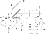
図1は第1の実施例の構成図である。被検眼Eに対向してダイクロイックミラー1が配置されており、その反射方向には前眼部観察用対物レンズ2、ダイクロイックミラー3が配置され、ダイクロイックミラー3の反射方向の光路O1上には結像レンズ4、被検眼Eの前眼部付近と略共役な位置にCCDカメラなどから成る撮像素子5が配置されている。被検眼前眼部を照明するための近赤外光を発するLEDなどの前眼部照明光源6が被検眼とダイクロイックミラー1との間の光軸外の位置に配置されている。そして、前眼部観察用対物レンズ2から撮像素子5によって前眼部観察光学系が構成されている。
【0007】
また、被検眼Eの角膜Ecに角膜形状測定用のリング指標を投影するための近赤外光を発するLEDなどのリング光源7が被検眼Eとダイクロイックミラー1との間の光軸外の位置に配置されている。なお、角膜形状測定光学系は前眼部観察光学系に含まれている。
【0008】
ダイクロイックミラー3の透過方向の光路O2上にはミラー8が配置され、このミラー8の反射方向には図示しない被検眼が固視するための固視標投影光学系が配置されている。
【0009】
一方、ダイクロイックミラー1の透過方向の光路O3上には、眼屈折力測定用対物レンズ9、孔あきミラー10、投影絞り11、投影レンズ12、指標板13、前眼部照明光源6よりも数10nm波長が長い近赤外光を発する眼屈折力測定光源14が配置されており、これらの眼屈折力測定用対物レンズ9から眼屈折力測定光源14により眼屈折力測定光投影光学系が構成されている。
【0010】
また、孔あきミラー10の反射方向には光軸外にリング絞り15が設けられ、その後方には円錐プリズム16、リレーレンズ17、CCDカメラなどから成る撮像素子18が配置されており、眼屈折力測定用対物レンズ9から撮像素子18により眼屈折力測定受光光学系が構成されている。
【0011】
ここで、ダイクロイックミラー1は眼屈折力測定光源14から発せられる波長光の大部分を透過し、一部分を反射して前眼部照明光源6から発せられた波長光を反射する特性を有しており、ダイクロイックミラー3は可視光を透過し近赤外光を反射する特性を有している。
【0012】
また、前述の観察光学系、固視標投影光学系、眼屈折力測定光投影光学系、眼屈折力測定受光光学系などにより被検眼検査部が構成されており、この被検眼検査部は図示しない3軸方向に移動することのできる架台の上に載置され、検者が操作桿を操作することにより、被検眼検査部を自在に移動することができ、これらの架台及び操作桿などにより位置合わせ手段が構成されている。
【0013】
図2はブロック回路構成図である。図1の撮像素子5及び18の出力はそれぞれA/Dコンバータ20及び21に接続され、それらの出力はそれぞれ画像メモリ22及び23に接続されていると共に、装置の全ゆる制御を行う演算処理部24に接続されている。演算処理部24には、この他に眼屈折力測定光源14及び被検眼検査部の操作を行う操作部25が接続されている。更に、演算処理部24にはD/Aコンバータ26を介してテレビモニタ27が順次に接続されている。
【0014】
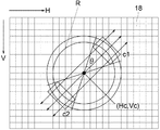
眼屈折力測定光源14からスポット像を被検眼Eの眼底Erに投影し、その反射光をリング絞り15、円錐プリズム16を用いてリング状にし、そのリング像を撮像素子18により撮像を行う。図3はこの撮像されたリング像Rを示しており、このリング像Rを楕円近似することにより被検眼Eの眼屈折力を求める。撮像された画像データは、A/Dコンバータ21によって撮像素子18の画素のそれぞれのデータとして画像メモリ23に転送され記憶される。楕円近似の方法として、図3に示すように水平方向H、垂直方向Vに画素に対応した座標をとり、この二次元座標の中心を(Hc,Vc)とする。
【0015】
図4及び図5はリング像Rに対するマスクと処理の流れを示している。入力画像をa1〜d2の8つのマスクに分ける。前述のように、マスク形状の長辺に対して垂直方向の線上のデータを用いて重心計算を行う。上述のマスク演算により求められた重心位置のデータを用いて、最小二乗法を使い楕円近似を行う。これにより求められた楕円から測定値である被検眼の屈折力、乱視、乱視軸角度が決定される。
【0016】
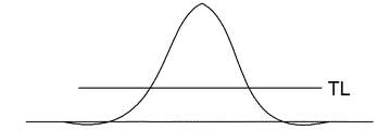
最初に、マスクa1、a2の演算を行う。図3に示すようにマスク形状の長辺に対して垂直方向の線上のデータを用いる。そこで、中心(Hc,Vc)の点からHcに1ずつ加算し、矢印に示すように走査を行うと図6の結果が得られる。
任意の閾値TLを定め、閾値TLよりも大きい走査線上のデータを用いて重心計算を行い、その線上の濃度中心を求め、濃度中心演算値の座標を楕円近似に用いる。今度は、Hcを1ずつ減算し、走査を行い同様の処理を行う。
【0017】
次に、Vcに任意のステップSを加算し、(1−Hc,Vc+S)の点から同様に走査を行い、上述と同様の処理を行う。更に、(Hc,Vc+2S)、(H−Hc,Vc+3S)、(Hc,Vc+4S)、・・・、と処理を行い、設定(Hc,Vc+aS)まで進むと、次はVcにSを減算した点(Hc,Vc−S)から水平方向に走査し処理を行う。同様に、設定(Hc,Vc−aS)まで処理を行う。ここで、aS、−aSは図3に示されているθで決定される。本実施例では、リング像Rを8つのマスクで分割しているためθ=45゜に設定されており、データの精度については十分に保証されている。
【0018】
続いて、マスクb1、b2の演算を行う。図7に示すようにマスクの長辺に対して垂直方向の線上のデータを用いる。中心(Hc,Vc)の点から、Vcに1ずつ加算及び減算し矢印方向に走査を行い、水平方向の走査と同様に走査線上のデータから重心座標を求める。Hcに任意のステップSを加算し、(Hc+S,Vc)、(Hc+2S,Vc)、(Hc+3S,Vc)、・・・、(H−Hc+aS,Vc)の点から垂直方向に走査し、重心座標を求める処理を行う。(Hc−S,Vc)、(Hc−2S,Vc)、(Hc−3S,Vc)、・・・、(Hc−aS,Vc)の点においても同様の処理を行う。
【0019】
更に、マスクc1、c2、d1、d2の演算を行う。これは図8及び図9に示される。図8に示すように、c1、c2のマスク形状の長辺に対して垂直方向の線上のデータを用いる。中心(Hc,Vc)の点からHcに1ずつ加算し、Vcに1ずつ減算し走査を行う。また、Hcに1ずつ減算し、Vcに1ずつ加算し矢印方向に走査し、その走査線上のデータから重心座標を求める。また、Hc及びVcに任意のステップSを加算し、(Hc+S,Vc+S)、(Hc+2S,Vc+2S)、(Hc+3S,Vc+3S)、・・・、(Hc+aS,Vc+aS)の点から斜め方向に走査し、重心座標を求める処理を行い、(Hc−S,Vc−S)、(Hc−2S,Vc−2S)、(Hc−3S,Vc−3S)、・・・、(Hc−aS,Vc−aS)の点においても同様の処理を行う。
【0020】
次に、図9に示すようにd1、d2のマスク形状の長辺に対して垂直方向の線上のデータを用いる。中心(Hc,Vc)の点から、Hc及びVcにそれぞれ1ずつ加算し矢印方向に走査を行う。また、Hc及びVcにそれぞれ1ずつ減算し走査し、その走査線上のデータから重心座標を求める。また、Hcに任意のステップSを加算、Vcに任意のステップSを減算し、(Hc+S,Vc−S)、(H=Hc+2S,Vc−2S)、(Hc+3S,Vc−3S)、・・・、(Hc+aS,Vc−aS)の点から斜め方向に走査し、重心座標を求める処理を行い、Hcに任意のステップSを減算、Vcに任意のステップSを加算し、(Hc−S,Vc+S)、(Hc−2S,Vc+2S)、(Hc−3S,Vc+3S)、・・・、(Hc−aS,Vc+aS)の点においても同様の処理を行う。
【0021】
このように、リング像Rに特定のマスクを用いることにより、リング像Rの走査方向に対して、斜め方向のリング位置のデータについても十分に信頼性のある演算結果を得ることができ、測定精度を向上させることできる。また、被検眼周辺部の睫毛等の影響により測定用の指標像であるリング像Rが欠けた場合でも、測定精度を向上することができる。なお、本実施例ではリング像に対して8角形のマスクを用いたが、他の多角形を用いることもできる。
【0022】
実際の測定を行う時には、雲霧などの予備測定と測定値を求める本測定がある。予備測定時には、処理時間の短縮のため、a1、a2、b1、b2のマスクの演算だけを行い、本測定時には、a1〜d2の全てのマスクについての演算を行うことも可能である。
【0023】
実施例においては、被検眼Eの眼屈折力の測定の説明を行ったが、同様の方法を角膜曲率半径の測定にも用いることができる。角膜形状測定リング光源7からのリング像を被検眼Eの角膜Ecに投影し、その反射光であるリング像Rを撮像素子5により撮像を行う。このリング像Rを楕円近似することにより、被検眼Eの角膜曲率半径を求める。撮像された画像データは、A/Dコンバータ20によって撮像素子5の画素のそれぞれのデータとして、画像メモリ22に転送され記憶される。楕円近似の方法は前述と同様の方法を用いることにより、角膜曲率半径の測定精度も向上させることができる。
【0024】
【発明の効果】
以上説明したように本発明に係る眼科装置は、被検眼周辺部の睫毛等の影響により測定用の指標像であるリング像が欠けた場合でも、リング像全周の精度保証が可能になり、被検眼の眼屈折力や角膜曲率半径等を精度良く求めることができる。
【0025】
また、このような分散処理を行うことにより、特定の角度にしか走査することができないが、角度を指定し走査を行う場合に比べて、処理を簡単にすることができ、処理時間の短縮にもつながる。
【図面の簡単な説明】
【図1】本実施例の光学系の構成図である。
【図2】ブロック回路構成図である。
【図3】水平方向の走査の説明図である。
【図4】リング像に対するマスクの説明図である。
【図5】楕円近似までの処理の説明図である。
【図6】走査線上のリング像の光量分布図である。
【図7】垂直方向の走査の説明図である。
【図8】第1斜め方向の走査の説明図である。
【図9】第2斜め方向の走査の説明図である。
【符号の説明】
2 前眼部観察用対物レンズ
5、18 撮像素子
6 前眼部照明光源
7 角膜形状測定リング光源
10 孔あきミラー
14 眼屈折力測定光源
22、23 画像メモリ
24 演算処理部
27 テレビモニタ
R 測定リング像[0001]
BACKGROUND OF THE INVENTION
The present invention relates to an ophthalmologic apparatus such as an autorefractometer that measures a fundus reflection image of a measurement index and obtains eye refractive power, and a keratometer that measures a cornea reflection image of a measurement index and obtains a corneal curvature radius.
[0002]
[Prior art]
Conventionally, when a ring index is used as an index for measurement, the index is projected onto the fundus or cornea of the eye to be examined, and the reflected image is captured by a sensor, Ideally, the ring position is detected by scanning radially from the center, but in reality it is processed as sampled matrix-like discrete data, so it is scanned horizontally and vertically, and the calculated data is converted into an ellipse. The eye refractive power and the corneal curvature radius of the eye to be examined are obtained by approximation.
[0003]
[Problems to be solved by the invention]
However, the above-described conventional example has a problem that the accuracy of detecting the ring position in the oblique direction is poor with respect to the scanning direction of the ring image. Therefore, if the data with high reliability in the horizontal or vertical part is not detected due to the effect of eyelashes around the eye to be inspected, the reliability of the calculation result will be low. There is.
[0004]
An object of the present invention is to provide an ophthalmologic apparatus that can solve the above-described problems and can accurately determine the eye refractive power and the corneal curvature radius.
[0005]
[Means for Solving the Problems]
To achieve the above object, an ophthalmologic apparatus according to the present invention includes a projecting unit that projects an index onto an eye to be examined, an imaging unit that captures a ring image obtained from the eye of the index through the ring diaphragm, Mask means for dividing the ring image picked up by the image pickup means into a plurality of masks, calculation means for calculating a density center based on pixel data on a line perpendicular to the long side of the mask, and results of the calculation means And calculating means for elliptically approximating the density center calculation values obtained from the respective masks obtained by the above.
[0006]
DETAILED DESCRIPTION OF THE INVENTION
The present invention will be described in detail based on the embodiments shown in the drawings.
FIG. 1 is a block diagram of the first embodiment. A
[0007]
In addition, a
[0008]
A
[0009]
On the other hand, on the optical path O <b> 3 in the transmission direction of the
[0010]
In addition, a
[0011]
Here, the
[0012]
Further, the above-described observation optical system, fixation target projection optical system, eye refractive power measurement light projection optical system, eye refractive power measurement light receiving optical system, and the like constitute an eye inspection unit. It is placed on a gantry that can be moved in three axis directions, and the examiner can move the eye examination unit freely by operating the joystick. With these gantry and joystick, etc. An alignment means is configured.
[0013]
FIG. 2 is a block circuit configuration diagram. The outputs of the
[0014]
A spot image is projected from the eye refractive power
[0015]
4 and 5 show a mask and processing flow for the ring image R. FIG. The input image is divided into eight masks a1 to d2. As described above, the center of gravity is calculated using data on a line perpendicular to the long side of the mask shape. Ellipse approximation is performed using the least square method using the data of the center of gravity obtained by the above mask calculation. Thus, the refractive power, astigmatism, and astigmatism axis angle of the eye to be inspected are determined from the obtained ellipse.
[0016]
First, the masks a1 and a2 are calculated. As shown in FIG. 3, data on a line perpendicular to the long side of the mask shape is used. Therefore, when one is added to Hc from the center (Hc, Vc) and scanning is performed as shown by the arrows, the result of FIG. 6 is obtained.
An arbitrary threshold value TL is determined, the center of gravity is calculated using data on the scanning line larger than the threshold value TL, the density center on the line is obtained, and the coordinates of the density center calculation value are used for elliptic approximation. This time, Hc is subtracted by 1 and scanning is performed to perform the same processing.
[0017]
Next, arbitrary step S is added to Vc, scanning is similarly performed from the point of (1−Hc, Vc + S), and the same processing as described above is performed. Further, processing is performed as (Hc, Vc + 2S), (H-Hc, Vc + 3S), (Hc, Vc + 4S),... The scanning is performed in the horizontal direction from (Hc, Vc-S). Similarly, processing is performed up to the setting (Hc, Vc-aS). Here, aS and -aS are determined by θ shown in FIG. In this embodiment, since the ring image R is divided by eight masks, θ = 45 ° is set, and the data accuracy is sufficiently guaranteed.
[0018]
Subsequently, the masks b1 and b2 are calculated. As shown in FIG. 7, data on a line perpendicular to the long side of the mask is used. From the center (Hc, Vc) point, Vc is incremented and decremented by one, scanning is performed in the direction of the arrow, and the barycentric coordinates are obtained from the data on the scanning line in the same manner as the horizontal scanning. Arbitrary step S is added to Hc, and scanning is performed in the vertical direction from the point (Hc + S, Vc), (Hc + 2S, Vc), (Hc + 3S, Vc),. The process which calculates | requires is performed. Similar processing is performed at the points (Hc-S, Vc), (Hc-2S, Vc), (Hc-3S, Vc),..., (Hc-aS, Vc).
[0019]
Further, the masks c1, c2, d1, and d2 are calculated. This is shown in FIGS. As shown in FIG. 8, data on a line perpendicular to the long sides of the mask shapes c1 and c2 are used. Scanning is performed by adding 1 to Hc from the center (Hc, Vc) and subtracting 1 from Vc. Also, 1 is subtracted from Hc, 1 is added to Vc, scanning is performed in the direction of the arrow, and the barycentric coordinates are obtained from the data on the scanning line. Also, an arbitrary step S is added to Hc and Vc, and scanning is performed obliquely from the points (Hc + S, Vc + S), (Hc + 2S, Vc + 2S), (Hc + 3S, Vc + 3S),..., (Hc + aS, Vc + aS), Processing for obtaining the coordinates of the center of gravity is performed, and (Hc-S, Vc-S), (Hc-2S, Vc-2S), (Hc-3S, Vc-3S), ..., (Hc-aS, Vc-aS) The same processing is also performed at point).
[0020]
Next, as shown in FIG. 9, data on a line perpendicular to the long sides of the mask shapes d1 and d2 are used. From the center (Hc, Vc), one is added to each of Hc and Vc, and scanning is performed in the direction of the arrow. Further, one is subtracted from Hc and Vc, respectively, and scanning is performed, and barycentric coordinates are obtained from data on the scanning line. Also, an arbitrary step S is added to Hc, an arbitrary step S is subtracted from Vc, (Hc + S, Vc−S), (H = Hc + 2S, Vc−2S), (Hc + 3S, Vc−3S),. , (Hc + aS, Vc-aS) is scanned obliquely from the point, and the process of obtaining the barycentric coordinates is performed. Any step S is subtracted from Hc, any step S is added to Vc, and (Hc-S, Vc + S). ), (Hc−2S, Vc + 2S), (Hc−3S, Vc + 3S),..., (Hc−aS, Vc + aS).
[0021]
Thus, by using a specific mask for the ring image R, sufficiently reliable calculation results can be obtained for the data of the ring position in the oblique direction with respect to the scanning direction of the ring image R. Accuracy can be improved. Further, even when the ring image R, which is an index image for measurement, is lost due to the influence of eyelashes or the like around the eye to be examined, the measurement accuracy can be improved. In this embodiment, an octagonal mask is used for the ring image, but other polygons may be used.
[0022]
When actual measurement is performed, there are preliminary measurement such as cloud fog and main measurement for obtaining a measurement value. In the preliminary measurement, only the masks a1, a2, b1, and b2 are calculated to shorten the processing time, and in the main measurement, the calculation for all the masks a1 to d2 can be performed.
[0023]
In the embodiment, the measurement of the eye refractive power of the eye E is described, but the same method can be used for the measurement of the corneal curvature radius. A ring image from the corneal shape measurement
[0024]
【The invention's effect】
As described above, the ophthalmologic apparatus according to the present invention can guarantee the accuracy of the entire circumference of the ring image even when the ring image, which is an index image for measurement, is lost due to the influence of eyelashes and the like around the subject eye, The eye refractive power, corneal curvature radius, etc. of the eye to be examined can be obtained with high accuracy.
[0025]
In addition, by performing such distributed processing, it is possible to scan only at a specific angle, but the processing can be simplified and the processing time can be shortened as compared with the case where scanning is performed by specifying an angle. Is also connected.
[Brief description of the drawings]
FIG. 1 is a configuration diagram of an optical system according to an embodiment.
FIG. 2 is a block circuit configuration diagram.
FIG. 3 is an explanatory diagram of scanning in the horizontal direction.
FIG. 4 is an explanatory diagram of a mask for a ring image.
FIG. 5 is an explanatory diagram of processing up to ellipse approximation.
FIG. 6 is a light amount distribution diagram of a ring image on a scanning line.
FIG. 7 is an explanatory diagram of scanning in the vertical direction.
FIG. 8 is an explanatory diagram of scanning in a first oblique direction.
FIG. 9 is an explanatory diagram of scanning in a second oblique direction.
[Explanation of symbols]
2 Anterior eye observation
Claims (8)
前記撮像光学系の光軸中心を互いに略均等な角度で通る少なくとも3つの線と、前記リング像との交点の座標をそれぞれ演算する交点座標演算手段と、
前記交点の座標を用いて前記リング像を楕円として近似する楕円近似手段と、
前記近似した楕円を用いて前記被検眼の眼屈折力と角膜曲率半径とのいずれかを演算する測定値演算手段と、
を有することを特徴とする眼科装置。 A ring image acquisition means for acquiring a ring image based on the reflected light of the eye to be examined via an imaging optical system;
Intersection coordinate calculation means for calculating the coordinates of the intersections of at least three lines passing through the optical axis centers of the imaging optical system at substantially equal angles and the ring image;
Ellipse approximation means for approximating the ring image as an ellipse using the coordinates of the intersection point;
A measurement value calculation means for calculating either the eye refractive power or the corneal curvature radius of the eye to be examined using the approximate ellipse;
An ophthalmologic apparatus comprising:
前記楕円の近似は前記濃度中心演算値を最小二乗法による演算によって行うことを特徴とする請求項1乃至4のいずれか1項に記載の眼科装置。 The coordinates of the intersection are density center calculation values calculated based on pixel data on the line,
The ophthalmic apparatus according to any one of claims 1 to 4 approximation of the ellipse and performing the calculation by the least square method the concentration center calculation value.
リング状の指標を前記被検眼に投影する投影手段と、
前記被検眼からのリング状の反射光を前記撮像光学系を介して前記リング像として撮像する撮像手段と、
を有することを特徴とする請求項1乃至5のいずれか1項に記載の眼科装置。 The ring image acquisition means;
Projection means for projecting a ring-shaped index onto the eye to be examined;
Imaging means for imaging the ring-shaped reflected light from the eye to be examined as the ring image via the imaging optical system;
The ophthalmologic apparatus according to claim 1, wherein the ophthalmologic apparatus is provided.
指標を前記被検眼に投影する投影手段と、Projection means for projecting an index onto the eye to be examined;
前記被検眼の反射光を前記撮像光学系のリング絞りを介して前記リング像として撮像する撮像手段と、Imaging means for imaging the reflected light of the eye to be examined as the ring image via a ring diaphragm of the imaging optical system;
を有することを特徴とする請求項1乃至5のいずれか1項に記載の眼科装置。The ophthalmologic apparatus according to claim 1, wherein the ophthalmologic apparatus is provided.
前記撮像光学系の光軸中心を互いに略均等な角度で通る少なくとも3つの線と、前記リング像との交点の座標をそれぞれ演算する工程と、
前記交点の座標を用いて前記リング像を楕円として近似する工程と、
前記近似した楕円を用いて前記被検眼の眼屈折力と角膜曲率半径とのいずれかを演算する工程と、
を含むことを特徴とする眼科測定方法。 Obtaining a ring image based on reflected light of the eye to be examined via an imaging optical system;
Calculating the coordinates of the intersection of at least three lines passing through the optical axis centers of the imaging optical system at substantially equal angles and the ring image, respectively;
Approximating the ring image as an ellipse using the coordinates of the intersection;
Calculating one of eye refractive power and corneal curvature radius of the eye to be examined using the approximated ellipse;
An ophthalmologic measurement method comprising:
Priority Applications (1)
| Application Number | Priority Date | Filing Date | Title |
|---|---|---|---|
| JP2000085633A JP4545871B2 (en) | 2000-03-27 | 2000-03-27 | Ophthalmic equipment |
Applications Claiming Priority (1)
| Application Number | Priority Date | Filing Date | Title |
|---|---|---|---|
| JP2000085633A JP4545871B2 (en) | 2000-03-27 | 2000-03-27 | Ophthalmic equipment |
Publications (3)
| Publication Number | Publication Date |
|---|---|
| JP2001269315A JP2001269315A (en) | 2001-10-02 |
| JP2001269315A5 JP2001269315A5 (en) | 2007-04-26 |
| JP4545871B2 true JP4545871B2 (en) | 2010-09-15 |
Family
ID=18601934
Family Applications (1)
| Application Number | Title | Priority Date | Filing Date |
|---|---|---|---|
| JP2000085633A Expired - Fee Related JP4545871B2 (en) | 2000-03-27 | 2000-03-27 | Ophthalmic equipment |
Country Status (1)
| Country | Link |
|---|---|
| JP (1) | JP4545871B2 (en) |
Cited By (1)
| Publication number | Priority date | Publication date | Assignee | Title |
|---|---|---|---|---|
| US9089290B2 (en) | 2012-10-18 | 2015-07-28 | Canon Kabushiki Kaisha | Ophthalmologic apparatus, ophthalmologic control method, and program |
Families Citing this family (2)
| Publication number | Priority date | Publication date | Assignee | Title |
|---|---|---|---|---|
| JP4280125B2 (en) * | 2003-07-31 | 2009-06-17 | 株式会社ニデック | Eye adjustment function measuring device |
| JP4653576B2 (en) * | 2005-07-01 | 2011-03-16 | 株式会社ニデック | Eye refractive power measuring device |
Citations (2)
| Publication number | Priority date | Publication date | Assignee | Title |
|---|---|---|---|---|
| JPH06142045A (en) * | 1992-11-05 | 1994-05-24 | Nikon Corp | Ophthalmic apparatus |
| JPH11225963A (en) * | 1998-02-13 | 1999-08-24 | Canon Inc | Optometry measuring device |
Family Cites Families (2)
| Publication number | Priority date | Publication date | Assignee | Title |
|---|---|---|---|---|
| JP2520804B2 (en) * | 1991-09-09 | 1996-07-31 | 本田技研工業株式会社 | Image processing method in optical measuring device |
| JPH09276221A (en) * | 1996-04-12 | 1997-10-28 | Canon Inc | Optometric device |
-
2000
- 2000-03-27 JP JP2000085633A patent/JP4545871B2/en not_active Expired - Fee Related
Patent Citations (2)
| Publication number | Priority date | Publication date | Assignee | Title |
|---|---|---|---|---|
| JPH06142045A (en) * | 1992-11-05 | 1994-05-24 | Nikon Corp | Ophthalmic apparatus |
| JPH11225963A (en) * | 1998-02-13 | 1999-08-24 | Canon Inc | Optometry measuring device |
Cited By (1)
| Publication number | Priority date | Publication date | Assignee | Title |
|---|---|---|---|---|
| US9089290B2 (en) | 2012-10-18 | 2015-07-28 | Canon Kabushiki Kaisha | Ophthalmologic apparatus, ophthalmologic control method, and program |
Also Published As
| Publication number | Publication date |
|---|---|
| JP2001269315A (en) | 2001-10-02 |
Similar Documents
| Publication | Publication Date | Title |
|---|---|---|
| JP5578542B2 (en) | Eye refractive power measuring device | |
| JPH0366356A (en) | Topography-measuring method and apparatus thereof | |
| JP3602371B2 (en) | Corneal shape measuring device | |
| JP2561828B2 (en) | Fundus examination device | |
| JP4716739B2 (en) | Eye refractive power measuring device | |
| JP4545871B2 (en) | Ophthalmic equipment | |
| US5781275A (en) | Eye refractometer and eye refractive power measuring apparatus for electro-optically measuring the refractive power of the eye | |
| JP3617705B2 (en) | Corneal endothelial cell imaging device | |
| JP3576656B2 (en) | Alignment detection device for ophthalmic instruments | |
| JP2000135200A (en) | Optometric apparatus | |
| JPH08562A (en) | Position detector for ophthalmological equipment | |
| JP2614324B2 (en) | Corneal shape measuring device | |
| JP3206936B2 (en) | Eye refractometer | |
| JP2002360516A (en) | Ophthalmological device | |
| JP2835371B2 (en) | Eye measurement device | |
| JP2580215B2 (en) | Objective eye refractometer | |
| JP3927873B2 (en) | Eye refractive power measuring device | |
| JP3004653B2 (en) | Ophthalmic equipment | |
| JP2005342284A (en) | Eye refractivity measuring device | |
| JPH01242029A (en) | Positioning apparatus of ophthalmic machines | |
| JP2003038442A (en) | Cornea shape measuring device | |
| JP3106127B2 (en) | Ophthalmic equipment | |
| JP2937373B2 (en) | Ophthalmic equipment | |
| JPH0898814A (en) | Ophthalmological device | |
| JP2004113685A (en) | Cornea profile measuring apparatus |
Legal Events
| Date | Code | Title | Description |
|---|---|---|---|
| A521 | Written amendment |
Free format text: JAPANESE INTERMEDIATE CODE: A523 Effective date: 20070309 |
|
| A621 | Written request for application examination |
Free format text: JAPANESE INTERMEDIATE CODE: A621 Effective date: 20070309 |
|
| A977 | Report on retrieval |
Free format text: JAPANESE INTERMEDIATE CODE: A971007 Effective date: 20100128 |
|
| RD01 | Notification of change of attorney |
Free format text: JAPANESE INTERMEDIATE CODE: A7421 Effective date: 20100218 |
|
| A131 | Notification of reasons for refusal |
Free format text: JAPANESE INTERMEDIATE CODE: A131 Effective date: 20100223 |
|
| A521 | Written amendment |
Free format text: JAPANESE INTERMEDIATE CODE: A523 Effective date: 20100419 |
|
| TRDD | Decision of grant or rejection written | ||
| A01 | Written decision to grant a patent or to grant a registration (utility model) |
Free format text: JAPANESE INTERMEDIATE CODE: A01 Effective date: 20100629 |
|
| A01 | Written decision to grant a patent or to grant a registration (utility model) |
Free format text: JAPANESE INTERMEDIATE CODE: A01 |
|
| A61 | First payment of annual fees (during grant procedure) |
Free format text: JAPANESE INTERMEDIATE CODE: A61 Effective date: 20100701 |
|
| FPAY | Renewal fee payment (event date is renewal date of database) |
Free format text: PAYMENT UNTIL: 20130709 Year of fee payment: 3 |
|
| R150 | Certificate of patent or registration of utility model |
Free format text: JAPANESE INTERMEDIATE CODE: R150 |
|
| LAPS | Cancellation because of no payment of annual fees |