JP4528112B2 - Optical switch and optical switch control device and control method - Google Patents
Optical switch and optical switch control device and control method Download PDFInfo
- Publication number
- JP4528112B2 JP4528112B2 JP2004376932A JP2004376932A JP4528112B2 JP 4528112 B2 JP4528112 B2 JP 4528112B2 JP 2004376932 A JP2004376932 A JP 2004376932A JP 2004376932 A JP2004376932 A JP 2004376932A JP 4528112 B2 JP4528112 B2 JP 4528112B2
- Authority
- JP
- Japan
- Prior art keywords
- output port
- reflected light
- mirror
- output ports
- incident
- Prior art date
- Legal status (The legal status is an assumption and is not a legal conclusion. Google has not performed a legal analysis and makes no representation as to the accuracy of the status listed.)
- Expired - Fee Related
Links
Images


Classifications
-
- G—PHYSICS
- G02—OPTICS
- G02B—OPTICAL ELEMENTS, SYSTEMS OR APPARATUS
- G02B6/00—Light guides; Structural details of arrangements comprising light guides and other optical elements, e.g. couplings
- G02B6/24—Coupling light guides
- G02B6/26—Optical coupling means
- G02B6/28—Optical coupling means having data bus means, i.e. plural waveguides interconnected and providing an inherently bidirectional system by mixing and splitting signals
- G02B6/293—Optical coupling means having data bus means, i.e. plural waveguides interconnected and providing an inherently bidirectional system by mixing and splitting signals with wavelength selective means
- G02B6/29379—Optical coupling means having data bus means, i.e. plural waveguides interconnected and providing an inherently bidirectional system by mixing and splitting signals with wavelength selective means characterised by the function or use of the complete device
- G02B6/29395—Optical coupling means having data bus means, i.e. plural waveguides interconnected and providing an inherently bidirectional system by mixing and splitting signals with wavelength selective means characterised by the function or use of the complete device configurable, e.g. tunable or reconfigurable
-
- G—PHYSICS
- G02—OPTICS
- G02B—OPTICAL ELEMENTS, SYSTEMS OR APPARATUS
- G02B6/00—Light guides; Structural details of arrangements comprising light guides and other optical elements, e.g. couplings
- G02B6/24—Coupling light guides
- G02B6/26—Optical coupling means
- G02B6/28—Optical coupling means having data bus means, i.e. plural waveguides interconnected and providing an inherently bidirectional system by mixing and splitting signals
- G02B6/293—Optical coupling means having data bus means, i.e. plural waveguides interconnected and providing an inherently bidirectional system by mixing and splitting signals with wavelength selective means
- G02B6/29304—Optical coupling means having data bus means, i.e. plural waveguides interconnected and providing an inherently bidirectional system by mixing and splitting signals with wavelength selective means operating by diffraction, e.g. grating
- G02B6/29305—Optical coupling means having data bus means, i.e. plural waveguides interconnected and providing an inherently bidirectional system by mixing and splitting signals with wavelength selective means operating by diffraction, e.g. grating as bulk element, i.e. free space arrangement external to a light guide
- G02B6/2931—Diffractive element operating in reflection
-
- G—PHYSICS
- G02—OPTICS
- G02B—OPTICAL ELEMENTS, SYSTEMS OR APPARATUS
- G02B6/00—Light guides; Structural details of arrangements comprising light guides and other optical elements, e.g. couplings
- G02B6/24—Coupling light guides
- G02B6/26—Optical coupling means
- G02B6/28—Optical coupling means having data bus means, i.e. plural waveguides interconnected and providing an inherently bidirectional system by mixing and splitting signals
- G02B6/293—Optical coupling means having data bus means, i.e. plural waveguides interconnected and providing an inherently bidirectional system by mixing and splitting signals with wavelength selective means
- G02B6/29304—Optical coupling means having data bus means, i.e. plural waveguides interconnected and providing an inherently bidirectional system by mixing and splitting signals with wavelength selective means operating by diffraction, e.g. grating
- G02B6/29305—Optical coupling means having data bus means, i.e. plural waveguides interconnected and providing an inherently bidirectional system by mixing and splitting signals with wavelength selective means operating by diffraction, e.g. grating as bulk element, i.e. free space arrangement external to a light guide
- G02B6/29311—Diffractive element operating in transmission
-
- G—PHYSICS
- G02—OPTICS
- G02B—OPTICAL ELEMENTS, SYSTEMS OR APPARATUS
- G02B6/00—Light guides; Structural details of arrangements comprising light guides and other optical elements, e.g. couplings
- G02B6/24—Coupling light guides
- G02B6/26—Optical coupling means
- G02B6/28—Optical coupling means having data bus means, i.e. plural waveguides interconnected and providing an inherently bidirectional system by mixing and splitting signals
- G02B6/293—Optical coupling means having data bus means, i.e. plural waveguides interconnected and providing an inherently bidirectional system by mixing and splitting signals with wavelength selective means
- G02B6/29304—Optical coupling means having data bus means, i.e. plural waveguides interconnected and providing an inherently bidirectional system by mixing and splitting signals with wavelength selective means operating by diffraction, e.g. grating
- G02B6/29305—Optical coupling means having data bus means, i.e. plural waveguides interconnected and providing an inherently bidirectional system by mixing and splitting signals with wavelength selective means operating by diffraction, e.g. grating as bulk element, i.e. free space arrangement external to a light guide
- G02B6/29313—Optical coupling means having data bus means, i.e. plural waveguides interconnected and providing an inherently bidirectional system by mixing and splitting signals with wavelength selective means operating by diffraction, e.g. grating as bulk element, i.e. free space arrangement external to a light guide characterised by means for controlling the position or direction of light incident to or leaving the diffractive element, e.g. for varying the wavelength response
-
- G—PHYSICS
- G02—OPTICS
- G02B—OPTICAL ELEMENTS, SYSTEMS OR APPARATUS
- G02B6/00—Light guides; Structural details of arrangements comprising light guides and other optical elements, e.g. couplings
- G02B6/24—Coupling light guides
- G02B6/26—Optical coupling means
- G02B6/35—Optical coupling means having switching means
- G02B6/351—Optical coupling means having switching means involving stationary waveguides with moving interposed optical elements
- G02B6/3512—Optical coupling means having switching means involving stationary waveguides with moving interposed optical elements the optical element being reflective, e.g. mirror
-
- G—PHYSICS
- G02—OPTICS
- G02B—OPTICAL ELEMENTS, SYSTEMS OR APPARATUS
- G02B6/00—Light guides; Structural details of arrangements comprising light guides and other optical elements, e.g. couplings
- G02B6/24—Coupling light guides
- G02B6/26—Optical coupling means
- G02B6/35—Optical coupling means having switching means
- G02B6/354—Switching arrangements, i.e. number of input/output ports and interconnection types
- G02B6/3544—2D constellations, i.e. with switching elements and switched beams located in a plane
- G02B6/3548—1xN switch, i.e. one input and a selectable single output of N possible outputs
- G02B6/355—1x2 switch, i.e. one input and a selectable single output of two possible outputs
-
- G—PHYSICS
- G02—OPTICS
- G02B—OPTICAL ELEMENTS, SYSTEMS OR APPARATUS
- G02B6/00—Light guides; Structural details of arrangements comprising light guides and other optical elements, e.g. couplings
- G02B6/24—Coupling light guides
- G02B6/26—Optical coupling means
- G02B6/35—Optical coupling means having switching means
- G02B6/354—Switching arrangements, i.e. number of input/output ports and interconnection types
- G02B6/3554—3D constellations, i.e. with switching elements and switched beams located in a volume
- G02B6/3556—NxM switch, i.e. regular arrays of switches elements of matrix type constellation
-
- G—PHYSICS
- G02—OPTICS
- G02B—OPTICAL ELEMENTS, SYSTEMS OR APPARATUS
- G02B6/00—Light guides; Structural details of arrangements comprising light guides and other optical elements, e.g. couplings
- G02B6/24—Coupling light guides
- G02B6/26—Optical coupling means
- G02B6/35—Optical coupling means having switching means
- G02B6/354—Switching arrangements, i.e. number of input/output ports and interconnection types
- G02B6/356—Switching arrangements, i.e. number of input/output ports and interconnection types in an optical cross-connect device, e.g. routing and switching aspects of interconnecting different paths propagating different wavelengths to (re)configure the various input and output links
Landscapes
- Physics & Mathematics (AREA)
- General Physics & Mathematics (AREA)
- Optics & Photonics (AREA)
- Mechanical Light Control Or Optical Switches (AREA)
Description
本発明は、光スイッチ並びに光スイッチの制御装置及び制御方法に関し、特に、反射面の角度を変えることにより光路を偏向して複数の出力ポートのいずれかに反射光を導く際に用いて好適な技術に関する。 The present invention relates to an optical switch and an optical switch control device and control method, and is particularly suitable for use in deflecting an optical path by changing the angle of a reflecting surface to guide reflected light to one of a plurality of output ports. Regarding technology.
従来、光伝送システムにおけるチャンネル切り替えは光信号から電気信号への変換後に電気スイッチにより行なわれていたが、光信号を電気信号に変換せずに、光信号として切り替えるスイッチ(光スイッチ)を用いることにより、チャンネル切り替えの速度や、効率を向上することができる。
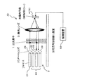
図13,図14及び図15に光スイッチの構成を示す。なお、図13は光スイッチの模式的斜視図、図14は光スイッチの模式的側面図、図15は光スイッチの模式的上面図である。
Conventionally, channel switching in an optical transmission system has been performed by an electrical switch after conversion from an optical signal to an electrical signal, but a switch (optical switch) that switches an optical signal as an optical signal without converting it to an electrical signal is used. As a result, the channel switching speed and efficiency can be improved.
The configuration of the optical switch is shown in FIGS. 13 is a schematic perspective view of the optical switch, FIG. 14 is a schematic side view of the optical switch, and FIG. 15 is a schematic top view of the optical switch.
これらの図13〜図15に示すように、光スイッチ10は、例えば、波長多重されたWDM(Wavelength Division Multiplex)光を波長に応じて(波長毎に)分光するための分光素子(分光手段)1と、アレイ状に配列された入力ポート(入力ファイバ)21、出力ポート(出力ファイバ)22および複数のコリメートレンズ〔コリメートレンズアレー(コリメート手段)〕23等を有する入出力光学系(入力光学系および出力光学系)2と、集光レンズ〔集光光学系(集光手段)〕3と、分光された複数の波長のそれぞれに対応させたMEMSミラー(光偏向手段)4を有する可動反射体70とをそなえて構成される。
As shown in FIGS. 13 to 15, the
上記の分光素子1には、例えば、透過型の回折格子が用いられ、この分光素子1は、入力ポート21からWDM光を入力され、このWDM光に含まれる波長成分を波長毎に異なる方向に分散して出力する。
また、上記の可動反射体70には、上記分光素子(回折格子)1による波長の分光(分散)方向にアレイ状に配列された光偏向手段としての複数のマイクロミラー(MEMSミラー)4が設けられており、各MEMSミラー4は、上記分光素子1により分光された光のうち、その配置位置に依存する自身への入射光を反射して、入出力光学系2における複数の出力ポート22のいずれかに導く波長選択スイッチとしての機能を有している。
For example, a transmissive diffraction grating is used for the
Further, the
出力ポート22の選択は、各MEMSミラー4の反射面の角度を変えることで行なうことができ、各MEMSミラー4それぞれ別個に反射面の角度制御を行なうことで、複数の波長について別個に異なるスイッチングを行なうことができる。
例えば図14及び図15中に示すように、1つのMEMSミラー4の反射面の角度を異なる出力ポート22に反射光を導くように変化させる(例えば、ポート21,22の配列方向に沿って変化させる)ことにより、入力ポート21から入力されたWDM光に含まれる所定の波長を出力ポート22のいずれかに振り分けることができるのである(例えば、下記特許文献1参照)。
The selection of the
For example, as shown in FIGS. 14 and 15, the angle of the reflection surface of one
また、各MEMSミラー4の角度を、出力ポート22を選択する際のダイナミックな動きではなく、微小変化させることにより、出力ポート22に入力される光強度を減衰させる(つまり、光アッテネータ機能を実現する)こともできる。
なお、各MEMSミラー4は、それぞれ、2軸動作が可能、つまり、図14に示すごとく分光方向に沿った方向(横方向)及び図15に示すごとく分光方向に垂直な方向(縦方向)のいずれにもミラー角度を変化させることができるようになっている。
Each
ところで、出力ポート22の切り替えに際して、隣接ポート22への切り替えであれば、出力ポート22の配列に沿った方向(分光方向に垂直な方向)にMEMSミラー4のミラー角度を変化させればよいが、非隣接ポート22への切り替えが必要な場合は、隣接ポート22への光の漏れ込みを避ける必要がある。
そこで、例えば図16に模式的に示すように、MEMSミラー4のミラー角度をまず横方向(分光方向に沿った方向)に変化させてビーム位置を切り替え前の出力ポート22(22a)の位置から横方向(分光方向)に離れた位置(出力ポート21への光の漏れ込みがない位置。これを光阻止領域11と呼ぶ)に移動(矢印A参照)させた後、ミラー角度を縦方向(分光方向に垂直な方向)に変化させてビーム位置を目的の出力ポート22(22c)の中心位置に相当する位置まで直線的に移動させ(矢印B参照)、次いで、再び、ミラー角度を横方向(ただし、最初とは逆方向)に変化させてビームを目的の出力ポート22(22c)に移動、入射させる(矢印C参照)ことが考えられる。
By the way, when the
Therefore, for example, as schematically shown in FIG. 16, the beam angle is first changed from the position of the output port 22 (22a) before switching by changing the mirror angle of the
このようなポート切り替えによれば、出力ポート22間の距離(ピッチ)を小さく(1.5mm程度)することができる。
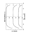
しかしながら、この切り替え動作では、出力ポートの切り替え(または、減衰)時の透過帯域特性が図17に示すようになる。この図17ではビームスポット径と回折の影響を含んだ帯域特性との関係を示しており、MEMSミラー4の角度を変化させたときの角度(0°,1.2°,1.5°,2.0°)別の複数の特性を示している。なお、この図17において、縦軸は透過強度(dB)、横軸はMEMSミラー4の幅(分光方向の長さ)を1(±0.5)としたときの波長帯域、即ち、規格化波長帯域を表している。この図17から分かるように、MEMSミラー4の角度が大きくなるほど、中央の平坦部分よりも上に凸状の透過帯域特性、即ち、透過帯域外近傍(サイドローブ部分)に盛上りが発生することが分かる。
According to such port switching, the distance (pitch) between the
However, in this switching operation, the transmission band characteristics when the output port is switched (or attenuated) are as shown in FIG. FIG. 17 shows the relationship between the beam spot diameter and the band characteristics including the influence of diffraction, and the angles (0 °, 1.2 °, 1.5 °, when the angle of the
図18にその原理を示す。
分光素子1による分光後の各ビームが中心波長であることを想定し、MEMSミラー4の中心位置に中心波長を有する各ビームがあたるように各MEMSミラー4が設定されていたとすると、実際に、WDM光に含まれる各波長が、中心波長からずれていなければ、各ビームは、図18の枠100において符号5cで示すようにMEMSミラー4の中心位置に照射されることとなる。
FIG. 18 shows the principle.
Assuming that each beam after spectroscopy by the
しかし、分光後の各ビームの中心波長がずれた場合(ずれた成分を含む場合)は、図18の枠100において符号5bや符号5dで示す位置に照射され、さらにずれると、図18の枠100において符号5aや符号5eで示すようにMEMSミラー4の端面側(分光方向についてのMEMSミラー4の端面側)に照射されることとなる。
ここで、注目すべきは、図18の枠100において示すように、MEMSミラー4の端面付近に入射ビームが照射された場合における反射ビーム6(6a,6e)は、入射ビーム5(5a,5e)の一部が削られるため、回折が生じ、MEMSミラー4の中心付近に入射された場合における反射ビーム6(6b〜6d)に比べて、スポット径が拡がってしまうことである。
However, when the center wavelength of each beam after the spectrum shifts (when the shifted component is included), it is irradiated to the positions indicated by
Here, it should be noted that the reflected beam 6 (6a, 6e) when the incident beam is irradiated in the vicinity of the end face of the
このようにスポット径が拡がってしまうと、図18の枠200において示すように、反射ビーム6の裾が盛り上がり(曲線9参照)、この裾部分では、MEMSミラー4中央付近からの反射ビーム6のパワー(曲線8参照)よりもビームパワーが大きくなる。つまり、MEMSミラー4の反射面の角度を分光方向に傾けた際には、端部で入射ビームが更に削られることとなるが、反射面を傾けることにより、反射ビーム6の裾部分のパワーをコリメートレンズ23の開口(面積)7で切り取る(符号7で示す部分に含まれる面積がその波長の透過強度となる)ことになるので、MEMSミラー4端面付近からの出力光強度の方が更に大きくなる。
When the spot diameter expands in this way, as shown in a
即ち、MEMSミラー4の端面(分光方向における端面)に向かうほど反射ビーム6が削られる量が増加していくために、先に説明した分光方向へのポートの切り替えに際して、回折の影響が強くなるという傾向がある。したがって、仮に回折の影響がない場合、反射光ビーム6が削られることによるビームパワーの変化のみとなるため、透過帯域特性は、台形状となるはずであるが、回折の影響を受けることによって、図17及び図18の左中央に示すような逆台形状の透過帯域特性が加わる。
That is, since the amount of the
なお、異なる波長の反射ビーム6のピークが空間的に同じ位置(波長の空間分離量=0)となっているのは、図18の枠300,400,500,600においてそれぞれ示すように、反射ビーム6が、集光光学系3により集光されるとともに、分光素子1における角度変更により並進化されるからである。また、図18の枠200において示す開口7の幅は、コリメートレンズ23を主とした出力光学系2までの開口を示し、コリメートレンズ23の面積に対応して幅は広くなる。
Note that the peaks of the
このように、中央の平坦部分よりも上に凸状の透過帯域特性、即ち、透過帯域外近傍(サイドローブ部分)に盛上りをもってしまうと、光システムで用いられる場合に、光アンプによる光増幅の際に凸部分も増幅してしまうためにS/N比を劣化させてしまうという課題が生じる。これは多段接続の際に特に顕著となるために、多段接続の数が限られてしまい自由度の高いシステム構成を構築することができない。 As described above, if the transmission band characteristic is convex above the flat portion at the center, that is, if there is a swell in the vicinity of the transmission band (side lobe portion), the optical amplification by the optical amplifier is used in an optical system. In this case, the convex portion is also amplified, which causes a problem that the S / N ratio is deteriorated. This is particularly noticeable at the time of multistage connection, so the number of multistage connections is limited, and a system configuration with a high degree of freedom cannot be constructed.
本発明は、このような課題に鑑み創案されたもので、光スイッチの透過帯域特性の帯域外近傍(サイドローブ部分)の盛上りを抑制できるようにすることを目的とする。 The present invention has been devised in view of such a problem, and an object thereof is to suppress the swell of the vicinity of the out-of-band (side lobe portion) of the transmission band characteristics of an optical switch .
上記の目的を達成するために、以下の光スイッチ並びに光スイッチの制御装置及び制御方法を用いることができる。即ち、
(1)本発明の光スイッチは、波長多重光を波長に応じて分光する分光素子と、前記分光素子による波長の分光方向とは異なる方向に配列された複数の出力ポートと、該分光素子で分光された光がそれぞれ入射されるとともに、反射面の角度を変えることにより反射光を該複数の出力ポートのいずれかに導くことが可能な、前記分光方向に配列された複数のミラーと、第1の出力ポートに入射している該反射光の入射位置を前記第1の出力ポートに隣接しない第2の出力ポートに変更する際、該反射光が前記第2の出力ポート以外の出力ポートに入射しないように、該反射光の入射位置を、前記複数の出力ポートの配列方向に変化させてから前記複数の出力ポートの配列方向に垂直な方向に変化させることにより前記第1の出力ポート外へ移動させ、前記複数の出力ポートの配列方向に垂直な方向に変化させてから前記複数の出力ポートの配列方向に変化させることにより前記第2の出力ポート内へ移動させるように、前記複数のミラーのうち対応するミラーの反射面の角度を制御する制御装置と、をそなえたことを特徴としている。
To achieve the above object, it is possible to use a control device and a control method of an optical switch and an optical switch below. That is,
(1) An optical switch of the present invention includes a spectroscopic element that splits wavelength-multiplexed light according to a wavelength, a plurality of output ports arranged in a direction different from the spectral direction of the wavelength by the spectroscopic element, and the spectroscopic element. with dispersed light is incident, respectively, a plurality of mirrors reflecting light that can be directed to one of said plurality of output ports, which are arranged in the spectral direction by changing the angle of the reflecting surface, the When the incident position of the reflected light incident on one output port is changed to a second output port not adjacent to the first output port , the reflected light is transmitted to an output port other than the second output port. The incident position of the reflected light is changed in the direction perpendicular to the arrangement direction of the plurality of output ports after changing the incident position of the reflected light in the arrangement direction of the plurality of output ports. Move to Is allowed, so as to move to the second output in a port by changing from changing in a direction perpendicular to the array direction of the plurality of output ports in the arrangement direction of the plurality of output ports, the plurality of mirrors a control device of which that control angle of the reflecting surface of the corresponding mirror, that is provided with a is characterized.
(2)また、本発明の光スイッチの制御装置は、波長多重光を波長に応じて分光する分光素子と、前記分光素子による波長の分光方向とは異なる方向に配列された複数の出力ポートと、該分光素子で分光された光がそれぞれ入射されるとともに、反射面の角度を変えることにより反射光を該複数の出力ポートのいずれかに導くことが可能な、前記分光方向に配列された複数のミラーとをそなえた光スイッチの制御装置であって、第1の出力ポートに入射している該反射光の入射位置を前記第1の出力ポートに隣接しない第2の出力ポートに変更する際、該反射光が前記第2の出力ポート以外の出力ポートに入射しないように、該反射光の入射位置を、前記複数の出力ポートの配列方向に変化させてから前記複数の出力ポートの配列方向に垂直な方向に変化させることにより前記第1の出力ポート外へ移動させ、前記複数の出力ポートの配列方向に垂直な方向に変化させてから前記複数の出力ポートの配列方向に変化させることにより前記第2の出力ポート内へ移動させるように、前記複数のミラーのうち対応するミラーの反射面の角度を制御するミラー制御手段をそなえたことを特徴としている。 (2) Further, the control device of the optical switch of the present invention includes a spectroscopic element that divides wavelength-multiplexed light according to a wavelength, and a plurality of output ports arranged in a direction different from the spectral direction of the wavelength by the spectroscopic element. A plurality of light beams that are split in the spectroscopic direction, and each of the light beams separated by the spectroscopic element is incident and the reflected light can be guided to any one of the plurality of output ports by changing the angle of the reflection surface. a control apparatus for an optical switch and equipped with a mirror, when changing an incident position of the reflected beam irradiated is incident on the first output port to a second output port which is not adjacent to the first output port The arrangement direction of the plurality of output ports is changed after changing the incident position of the reflection light in the arrangement direction of the plurality of output ports so that the reflection light does not enter the output ports other than the second output port. Perpendicular to The second output port is moved out of the first output port by changing in the direction, changed in the direction perpendicular to the arrangement direction of the plurality of output ports, and then changed in the arrangement direction of the plurality of output ports. to move into in the output port, and characterized in that includes a mirror control unit that controls the angle of the reflecting surface of a corresponding mirror among the plurality of mirrors.
(3)ここで、該ミラー制御手段は、いずれかの出力ポートへ該反射光を入射させる際、該ミラーの配列方向以外の方向から該反射光を移動させて入射させるべく、対応する前記ミラーの反射面の角度を該ミラーの配列方向以外の方向に変化させるように構成されていてもよい。
(4)また、該ミラー制御手段は、いずれかの出力ポートに入射している反射光の入射位置を隣接しない他の出力ポートに変更する際に、当該反射光の入射位置を該ミラーの配列方向以外の方向へ移動させてから、該ミラーの配列方向及び当該配列方向以外の方向への該入射位置の移動を組み合わせて前記光を上記他の出力ポートへ入射させるべく、該ミラーの反射面の角度を制御するように構成されていてもよい。
(3) Here, when the reflected light is incident on any one of the output ports, the mirror control unit moves the reflected light from a direction other than the arrangement direction of the mirrors to make the reflected light incident. The angle of the reflecting surface of the mirror may be changed in a direction other than the arrangement direction of the mirrors.
(4) Further, when the mirror control means changes the incident position of the reflected light incident on any output port to another output port that is not adjacent, the incident position of the reflected light is arranged in the arrangement of the mirrors. In order to cause the light to be incident on the other output port by combining movement of the incident position in a direction other than the arrangement direction and the arrangement direction of the mirror after the movement in a direction other than the direction of the mirror, The angle may be controlled.
(5)さらに、該ミラーは、該ミラーの配列方向及び当該配列方向と直交する方向にそれぞれ該反射面の角度を変更しうるよう2軸動作可能に構成されていてもよい。 (5) In addition, the mirror may be respectively in the direction you orthogonal to the arrangement direction and the arrangement direction of the mirror is biaxially operatively configured as to be able to change the angle of the reflecting surface.
(6)また、該ミラー制御手段は、前記第1の出力ポートに入射している該反射光の入射位置を前記複数の出力ポートの配列方向に変化させる際、前記第1の出力ポートに隣接する出力ポートにおける光パワーをモニタし、そのモニタ値が許容クロストークレベルを超えないように該ミラーの反射面の角度を制御するように構成されていてもよい。
(7)さらに、該ミラー制御手段は、前記第1の出力ポートに隣接する出力ポートにおける光パワーが許容クロストークレベルを超えないようにあらかじめ決められた設計角度となるように該ミラーの反射面の角度を制御するように構成されていてもよい。
(6) Further, the mirror control means is adjacent to the first output port when changing the incident position of the reflected light incident on the first output port in the arrangement direction of the plurality of output ports. The optical power at the output port may be monitored, and the angle of the reflecting surface of the mirror may be controlled so that the monitored value does not exceed the allowable crosstalk level.
(7) Further, the mirror control means may reflect the reflecting surface of the mirror so that the optical power at the output port adjacent to the first output port has a predetermined design angle so as not to exceed an allowable crosstalk level. The angle may be controlled.
(8)なお、該出力ポート間の距離は、該ミラー制御手段による前記第1の出力ポートに隣接する出力ポートへ向けての該入射位置の移動時に、移動元の出力ポートにおける光透過帯域特性が所定の設計減衰レベル以下になり、かつ、上記隣接する出力ポートにおける光透過帯域特性が許容クロストークレベルを超えない範囲となるよう設定されているのが好ましい。
(9)また、本発明に関連する技術の光スイッチの制御装置は、波長多重光を波長に応じて分光する分光素子と、複数の出力ポートと、該分光素子で分光された光がそれぞれ入射されるとともに、反射面の角度を変えることにより反射光を該複数の出力ポートのいずれかに導くことが可能な複数のミラーとをそなえた光スイッチの制御装置であって、いずれかの出力ポートに入射している該反射光の入射位置を変更する際、当該出力ポートにおける光透過帯域特性のサイドローブ部分についての許容透過率を超えない範囲で、前記複数のミラーのうち対応する前記ミラーの反射面の角度を該ミラーの配列方向に変化させるミラー制御手段をそなえたことを特徴としている。
(8) The distance between the output ports when moving the incident position toward the output port adjacent to said first output port by the mirror controlling means, the light transmission band characteristic at the source output port Is set to be in a range where the light transmission band characteristic at the adjacent output port does not exceed the allowable crosstalk level.
(9) Further, the control device of the optical switch according to the technology related to the present invention includes a spectroscopic element that splits wavelength-multiplexed light in accordance with the wavelength, a plurality of output ports, and light that has been split by the spectroscopic element. And a control device for an optical switch comprising a plurality of mirrors capable of guiding reflected light to any one of the plurality of output ports by changing the angle of the reflecting surface. When changing the incident position of the reflected light incident on the side of the plurality of mirrors within a range that does not exceed the permissible transmittance for the side lobe portion of the light transmission band characteristic at the output port, It is characterized by comprising mirror control means for changing the angle of the reflecting surface in the direction of arrangement of the mirrors.
(10)さらに、本発明の光スイッチの制御方法は、波長多重光を波長に応じて分光する分光素子と、前記分光素子による波長の分光方向とは異なる方向に配列された複数の出力ポートと、該分光素子で分光された光がそれぞれ入射されるとともに、反射面の角度を変えることにより反射光を該複数の出力ポートのいずれかに導くことが可能な、前記分光方向に配列された複数のミラーとをそなえた光スイッチの制御方法であって、第1の出力ポートに入射している該反射光の入射位置を前記第1の出力ポートに隣接しない第2の出力ポートに変更する際、該反射光が前記第2の出力ポート以外の出力ポートに入射しないように、該反射光の入射位置を、前記複数の出力ポートの配列方向に変化させてから前記複数の出力ポートの配列方向に垂直な方向に変化させることにより前記第1の出力ポート外へ移動させ、前記複数の出力ポートの配列方向に垂直な方向に変化させてから前記複数の出力ポートの配列方向に変化させることにより前記第2の出力ポート内へ移動させるように、前記複数のミラーのうち対応するミラーの反射面の角度を制御することを特徴としている。 (10) Further, the optical switch control method of the present invention includes a spectroscopic element that splits wavelength-multiplexed light according to a wavelength, and a plurality of output ports arranged in a direction different from the spectral direction of the wavelength by the spectroscopic element. A plurality of light beams that are split in the spectroscopic direction, and each of the light beams separated by the spectroscopic element is incident and the reflected light can be guided to any one of the plurality of output ports by changing the angle of the reflection surface. a control method of an optical switch and equipped with a mirror, when changing an incident position of the reflected beam irradiated is incident on the first output port to a second output port which is not adjacent to the first output port The arrangement direction of the plurality of output ports is changed after changing the incident position of the reflection light in the arrangement direction of the plurality of output ports so that the reflection light does not enter the output ports other than the second output port. In The first output port is moved out of the first output port by changing in a straight direction, the direction is changed in a direction perpendicular to the arrangement direction of the plurality of output ports, and then changed in the arrangement direction of the plurality of output ports. to move to the second output in a port, is characterized that you control the angle of the reflecting surface of the mirror corresponding one of said plurality of mirrors.
(11)また、本発明に関連する技術の光スイッチの制御方法は、波長多重光を波長に応じて分光する分光素子と、複数の出力ポートと、該分光素子で分光された光がそれぞれ入射されるとともに、反射面の角度を変えることにより反射光を該複数の出力ポートのいずれかに導くことが可能な複数のミラーとをそなえた光スイッチの制御方法であって、いずれかの出力ポートに入射している該反射光の入射位置を変更する際、当該出力ポートにおける光透過帯域特性のサイドローブ部分についての許容透過率を超えない範囲で、前記複数のミラーのうち対応する前記ミラーの反射面の角度を該ミラーの配列方向に変化させることを特徴としている。 (11) Further, the optical switch control method according to the technology related to the present invention includes a spectroscopic element that splits wavelength-multiplexed light according to a wavelength, a plurality of output ports, and light that has been split by the spectroscopic element. And a method of controlling an optical switch comprising a plurality of mirrors capable of guiding reflected light to any one of the plurality of output ports by changing the angle of the reflecting surface. When changing the incident position of the reflected light incident on the side of the plurality of mirrors within a range that does not exceed the permissible transmittance for the side lobe portion of the light transmission band characteristic at the output port, The angle of the reflecting surface is changed in the arrangement direction of the mirrors.
(12)さらに、本発明に関連する技術の光スイッチは、入力光の分光を行なう分光部と、少なくとも2つの出力ポートとを備え、偏向手段によって分光後の光の出力先のポートを該2つの出力ポート間で切り替え可能な光スイッチにおいて、該切替の過程において、少なくとも切替元、切替先のいずれかの出力ポートの近傍部に反射光を導く際に、分光の方向と垂直な方向に反射光を移動させる過程を含み、この近傍部以外においては、分光方向に反射光を移動させる過程を含む制御を行なう制御部、を備えたことを特徴としている。
(13)また、該ミラー制御手段は、前記第1の出力ポートに入射している該反射光の入射位置を変更して前記第1の出力ポートに入力される光強度を減衰させる際、該反射光の入射位置を、前記第1の出力ポートへの該反射光の透過率が所定の設定減衰レベル以下、且つ、前記第1の出力ポートに隣接する出力ポートへの該反射光の漏れ込みが所定の許容クロストークレベルを超えない範囲で、前記複数の出力ポートの配列方向に最初に変化させるように、前記複数のミラーのうち対応するミラーの反射面の角度を制御するように構成されていてもよい。
(14)さらに、前述の光スイッチの制御方法において、前記第1の出力ポートに入射している該反射光の入射位置を変更して前記第1の出力ポートに入力される光強度を減衰させる際、該反射光の入射位置を、前記第1の出力ポートへの該反射光の透過率が所定の設定減衰レベル以下、且つ、前記第1の出力ポートに隣接する出力ポートへの該反射光の漏れ込みが所定の許容クロストークレベルを超えない範囲で、前記複数の出力ポートの配列方向に最初に変化させるように、前記複数のミラーのうち対応するミラーの反射面の角度を制御してもよい。
(12) Furthermore, an optical switch according to a technique related to the present invention includes a spectroscopic unit that performs spectroscopic analysis of input light, and at least two output ports. In an optical switch that can be switched between two output ports, during the switching process, the reflected light is reflected in a direction perpendicular to the spectral direction when guiding reflected light to the vicinity of at least the output port of either the switching source or the switching destination. A control unit is included that includes a process of moving light, and a control unit that performs control including a process of moving reflected light in the spectroscopic direction except for the vicinity.
(13) Further, the mirror control means when attenuating the light intensity input to the first output port by changing the incident position of the first reflected light which is incident on the output port, said the incident position of the reflected light, the transmittance of the reflected light to the first output port is below a predetermined set attenuation level, and, in the reflected light to the first output port to be that output port adjacent The angle of the reflecting surface of the corresponding mirror among the plurality of mirrors is controlled so that the leakage does not exceed a predetermined allowable crosstalk level and is first changed in the arrangement direction of the plurality of output ports. It may be configured .
(14) Further, in the method of controlling an optical switch described above, attenuating light intensity input by changing the incident position to the first output port of said first reflected light which is incident on the output port time, the incident position of the reflected light, the first reflected light transmittance prescribed set attenuation level to the output port or less, said to the first output port you adjacent to the output port The angle of the reflecting surface of the corresponding mirror among the plurality of mirrors is controlled so that the reflected light leaks first in the arrangement direction of the plurality of output ports within a range that does not exceed a predetermined allowable crosstalk level. May be .
上記の本発明によれば、出力ポートにおける透過帯域特性における帯域外近傍(サイドローブ)の盛上り量を非常に少なくできる。
また、それにより、S/Nを劣化させることなく光アンプによる光増幅が可能となる。
また、多段接続が可能となり、自由度の高い光システムを構築することができるようになる。
According to the present invention, the amount of swell in the vicinity of the out-of-band (side lobe) in the transmission band characteristic at the output port can be greatly reduced.
Thereby, optical amplification by the optical amplifier is possible without degrading S / N.
In addition, multistage connection is possible, and an optical system with a high degree of freedom can be constructed.
特に、帯域特性を平坦にできるため、帯域毎に割り振られた各波長(チャンネル)同士の光レベルを均一にすることができ、波長多重された光の全帯域における信号品質の改善を図ることができるようになる。 In particular, since the band characteristics can be flattened, the optical level of each wavelength (channel) allocated for each band can be made uniform, and the signal quality in the entire band of wavelength multiplexed light can be improved. become able to.
〔A〕一実施形態の説明
図1は本発明の一実施形態としての光スイッチの構成を示す模式的側面図であって、図14と対応する図である。この図1に示すように、本実施形態の光スイッチ10も、図13〜図15により前述したものと同様に、例えば、波長多重されたWDM光を波長に応じて(波長毎に)分光するための分光素子(分光手段、分光部)1と、アレイ状に配列された入力ポート(入力ファイバ)21、出力ポート(出力ファイバ)22および複数のコリメートレンズ〔コリメートレンズアレー(コリメート手段)〕23等を有する入出力光学系(入力光学系および出力光学系)2と、集光光学系(集光手段)3と、分光された複数の波長のそれぞれに対応(例えば、各チャネルについての各中心波長のそれぞれに対応)させたMEMSミラー(光偏向手段、偏向手段)4を有する可動反射体70とをそなえて構成され、各MEMSミラー4は、制御装置(ミラー制御手段、制御部)50によって個別に制御されるようになっている。
[A] Description of One Embodiment FIG. 1 is a schematic side view showing a configuration of an optical switch as one embodiment of the present invention, and corresponds to FIG. As shown in FIG. 1, the
ここで、出力ポート22は、例えば一列(分光方向と垂直な方向)に並んで配置されており、光偏向手段としてのMEMSミラー4は、例えば一列(分光方向)に並んで配置されているものとする。
但し、全ての出力ポート22を一列に配置しない場合も考えられる。例えば、少なくとも2つの出力ポート22が配置されており、少なくとも1つのMEMSミラー4により、この2つの出力ポート22間でスイッチ可能な構成であれば足りる。従って、以下説明する2つの出力ポート22間の切り替えを、この2つの出力ポート22間における切り替えとして扱うこともできることに留意すべきである。
Here, the
However, there may be a case where all the
なお、本実施形態においても、各MEMSミラー4は、それぞれ、少なくとも2軸動作が可能、つまり、分光方向(MEMSミラー4の配列方向)に沿った方向(横方向)及び分光方向に垂直な方向(出力ポート22の配列方向;縦方向)のいずれにもミラー角度を変化させることができるようになっている。また、以下において、既述の符号と同一符号を付して説明するものは、特に断らない限り、既述のものと同一若しくは同様のものである。
Also in this embodiment, each
ここで、図16により前述したのと同様に、例えば出力ポート22aに入射していた反射ビーム6の入射位置を他のポート(ここでは、非隣接ポートであるが隣接ポートであってもよい)である出力ポート22cに切り替える場合、本実施形態においては、制御装置50によって、例えば図2に模式的に示すごとく、まず、分光方向とは異なる方向(例えば分光方向に垂直な方向)にミラーの反射面を傾け、その後隣接ポートを迂回して非隣接ポートに導くようにMEMSミラー4のミラー角度を制御する。
Here, in the same manner as described above with reference to FIG. 16, for example, the incident position of the reflected
好ましくは、非隣接ポートに導く際にも、分光方向とは異なる方向に向けられたミラーの反射面を最終的に分光方向に傾けるようにMEMSミラー4のミラー角度を制御する。
即ち、制御装置50は、まず、MEMSミラー4のミラー角度を縦方向(例えば分光方向に垂直な方向)に変化させて隣接する出力ポート22bへ向かう方向(分光方向に垂直な方向)に反射ビーム6の入射位置を移動させる(矢印A参照)。なお、このときの移動量は、隣接する出力ポート22bへの光の漏れ込みが例えば図5により後述する許容クロストークレベルを超えない範囲に制御される。より詳細には、制御装置50は、例えば、出力ポート22bへの入射光のパワーをモニタしながら、そのモニタ値が許容クロストークレベルを超えない範囲でミラー角度を制御してビーム位置を移動させる場合と、あらかじめ許容クロストークレベルを超えないよう決められた設計値位置まで移動させる(つまり、前記許容クロストークレベルを超えないようにあらかじめ決められた設計角度となるようにMEMSミラー4の反射面の角度を制御する。以下、同じ)2通りの方法が可能である。
Preferably, when guiding to the non-adjacent port, the mirror angle of the
That is, the
次いで、制御装置50は、上記ミラー角度を今度は横方向(例えば、分光方向)に変化させてビーム入射位置を光阻止領域11へ移動させた後(矢印B参照)、さらに上記ミラー角度を縦方向に変化させて光阻止領域11上を直線的に目的の出力ポート22c側へ移動(例えば、分光方向と垂直な方向に移動)させる(矢印C参照)。このとき、出力ポート22b,22c間にビーム位置を移動させた場合に目的出力ポート22cと隣接する出力ポート22bへの光の漏れ込みが前記許容クロストークレベルを超えない位置(矢印Eの始点)に相当する光阻止領域11上の位置まで、ビーム位置を移動させる。詳細には、この場合も、制御装置50は、例えば、出力ポート22bへの入射光のパワーをモニタしながら、そのモニタ値が許容クロストークレベルを超えない位置までミラー角度を制御してビーム位置を移動させる場合と、あらかじめ許容クロストークレベルを超えないよう決められた設計値位置まで移動させる2通りの方法が可能である。
Next, the
そして、制御装置50は、再度、上記ミラー角度を横(分光)方向(ただし、最初の横方向変化とは逆方向)に変化させてビーム位置を直線的に目的の出力ポート22cの中心に相当する位置まで移動させ(矢印D参照)、最後に、再度、上記ミラー角度を縦方向(分光方向に垂直な方向)に変化させてビーム位置を目的の出力ポート22cの中心に移動させる(矢印E参照)。
Then, the
即ち、制御装置50は、切替先の出力ポート22cへ反射光を入射させるように切替を行う際に、切替元の出力ポート22aの中心部に導いていた光をまず、MEMSミラー4の配列方向(横方向)以外の方向(縦方向)に移動させ、更に、切替先の出力ポート22cまでの間に介在する他の出力ポートを迂回(回避)しながら移動させ、最終的には、MEMSミラー4の配列方向(横方向)以外の方向(縦方向)に移動させて切替先の出力ポート22cの中心部に光を導くのである。
That is, when the
以上のように、ポート切り替え(又は、減衰)動作において、隣接するポート方向(縦方向)への光の偏向動作を初期に行なうことで、当該方向と垂直な方向(横方向)への光の偏向動作を行なった場合に比して、透過帯域特性における帯域外近傍(サイドローブ部分)の盛上り量を非常に少なくすることができる。同様に、最終的に、目的の出力ポート22cへビーム位置を移動させる場合にも、縦方向に移動させることで、横方向への偏向動作で移動させて目的の出力ポート22cへ入射させる場合に比して、透過帯域特性における帯域外近傍の盛上り量を非常に少なくすることができる。
As described above, in the port switching (or attenuation) operation, by initially performing the light deflection operation in the adjacent port direction (vertical direction), the light in the direction perpendicular to the direction (lateral direction) Compared to the case where the deflection operation is performed, the amount of swell in the vicinity of the out-of-band (side lobe portion) in the transmission band characteristic can be greatly reduced. Similarly, when the beam position is finally moved to the
これは、例えば図3に符号A,B,C,Dで模式的に示すように、分光方向(波長分散方向)、つまり、MEMSミラー4の光反射面上でのビーム移動方向が横方向(分光方向に沿った方向)なために、横方向ではビーム6の削られと同時に回折の影響が発生する(符号B参照)のに対して、縦方向(分光方向と垂直な方向)ではビーム6の削られがビーム縦方向の中心線60を過ぎてから(符号D参照)回折の影響が発生するからである。
For example, as schematically shown by reference signs A, B, C, and D in FIG. 3, the spectral direction (wavelength dispersion direction), that is, the beam moving direction on the light reflection surface of the
即ち、図4に示すように、横方向の偏向動作では、開口7において図3中の符号Aの状態に比して図3中の符号B,C,Dのパワーの上回りが大きく、透過帯域特性における帯域外近傍の盛上りが大きいのに対して、縦方向の偏向動作では、開口7において図3中の符号Aの状態に比して図3中の符号B,C,Dのパワーの上回りが小さく、例えば図5に示すように、透過帯域特性における帯域外近傍の盛上りが小さいのである。なお、この図5に示す各特性は、上から順に、MEMSミラー4の傾きが0°、0.2°、0.3°のときの透過帯域特性をそれぞれ示している。
That is, as shown in FIG. 4, in the lateral deflection operation, the power of symbols B, C, and D in FIG. 3 is larger in the
したがって、上述のごとく、隣接するポート方向(縦方向)への光の偏向動作を初期に行なってから、当該方向と垂直な方向(横方向)への光の偏向動作を行なうとともに、目的の出力ポート22へのビーム位置の移動に際しても、縦方向への光の偏向動作でビーム位置を移動させて入射させることで、透過帯域特性における帯域外近傍の盛上り量を非常に少なくできるのである。
Therefore, as described above, the light deflection operation in the adjacent port direction (vertical direction) is initially performed, and then the light deflection operation in the direction perpendicular to the direction (lateral direction) is performed and the target output is performed. Even when the beam position is moved to the
その結果、S/Nを劣化させることなく光アンプによる光増幅が可能となるために、多段接続が可能となり、自由度の高い光システムを構築することができるようになる。特に、帯域特性を平坦にできるため、帯域毎に割り振られた各チャンネル同士の光信号レベルを均一にすることができ、多重化された光信号の全帯域における信号品質の改善を図ることができるようになる。 As a result, since optical amplification by an optical amplifier is possible without degrading S / N, multistage connection is possible, and an optical system with a high degree of freedom can be constructed. In particular, since the band characteristics can be flattened, the optical signal level of each channel allocated for each band can be made uniform, and the signal quality in the entire band of the multiplexed optical signal can be improved. It becomes like this.
なお、隣接する出力ポート22への切り替えを行なう場合は、光阻止領域11へビーム位置を移動させることなく、直接、目的の出力ポート22へビーム位置を移動させればよい。
ところで、上述ごとく縦方向の偏向動作を行なう場合には、隣接する出力ポート22へ向けてビーム6を移動させるため、設計減衰レベル及び許容クロストークレベルに基づいてポート間距離の最適化を行なう必要がある。即ち、例えば図6中右側に示すように、ある設計減衰レベル及び許容クロストークレベルが定められている場合、縦方向への偏向動作時において、移動元の出力ポート(初期接続ポート)22へのビーム6の透過率〔透過強度(透過帯域特性:曲線40参照)〕が前記設定減衰レベル以下になる範囲で、かつ、隣接ポート22へのビーム6の漏れ込み(透過帯域特性:曲線50参照)が前記許容クロストークレベルを超えない範囲となるように、ポート間距離を設計(設定)する。なお、曲線40は、MEMSミラー4を縦方向に約0.2°傾けたときの透過帯域特性を表し、曲線50は、MEMSミラー4を縦方向に約0.3°、横方向に約2.5°傾けたときの透過帯域特性を現している。
When switching to the
By the way, when the vertical deflection operation is performed as described above, the
このため、ポート間ピッチは、従来(最小ピッチ)よりも広げる必要がある。
このように、ポート間距離を設計することにより、例えば図7に示すように、初期の縦方向への偏向動作(矢印A参照)においては、その始点と終点でそれぞれ曲線80,90に示すような透過帯域特性を有することになり、透過帯域外近傍で盛上がりの少ない平坦な特性を得ることができ、その後の横方向への偏向動作では、その終点において曲線100に示すような、透過帯域外近傍で盛上がりのある透過帯域特性を有するが、光阻止領域11による光阻止レベル以下の範囲にあるため、その影響を受けることがない。なお、終期の縦方向(目的出力ポート)への偏向動作(矢印E参照)においても同様である。また、図7において、曲線80はMEMSミラー4の傾きが0°、曲線90はMEMSミラー4の傾きが約0.25°、曲線100はMEMSミラー4の傾きが縦方向に約0.3°で横方向に約2.0°のときの透過帯域特性をそれぞれ示している。
For this reason, it is necessary to increase the pitch between ports more than the conventional (minimum pitch).
In this way, by designing the distance between the ports, as shown in FIG. 7, for example, in the initial vertical deflection operation (see arrow A), the start point and the end point are shown by
(A1)第1変形例
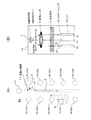
図8(B)に示すように、上述した各MEMSミラー4が、それぞれ、両横振り型MEMSミラーとして構成されている場合、即ち、横方向(分光方向)のいずれにもミラー角度を変更できるようになっている場合、例えば図8(A)に示すように入力ポート21及び出力ポート22を配列することができる。即ち、1個の入力ポート21に対して10個の出力ポート22(22a〜22j)を2列配列する。尚、各配列は、分光方向と垂直な方向とすることができる。なお、本例においても、図6及び図7により上述したようにして各列における出力ポート22のポート間距離および各列間の距離が設計減衰レベル及び許容クロストークレベルに基づいて設計(設定)される。
(A1) First Modified Example As shown in FIG. 8B, when each of the above-described MEMS mirrors 4 is configured as a both-side swing type MEMS mirror, that is, in any of the lateral direction (spectral direction). If the mirror angle can be changed, the
そして、この図8(A)中に示すように、右列最上段の出力ポート22に入射していた反射ビームを左列4番目の出力ポート22に入射させる場合、制御装置50は、まず、対応するMEMSミラー4のミラー角度を縦方向に変更して当該出力ポート22に入射していた反射ビームのビーム入射位置を隣接する出力ポート(右列2番目の出力ポート)22bに向けて直線的に移動させる(矢印A参照)。この場合も、制御装置50は、例えば、出力ポート22bへの入射光のパワーをモニタし、そのモニタ値が許容クロストークレベルを超えない範囲でミラー角度を制御してビーム位置を移動させる場合と、あらかじめ許容クロストークレベルを超えないよう決められた設計値位置まで移動させる2通りの方法が可能である。
As shown in FIG. 8A, when the reflected beam that has been incident on the
次いで、制御装置50は、上記MEMSミラー4のミラー角度を横方向に変更して反射ビームの入射位置を光阻止領域11まで直線的に移動させた後(矢印B参照)、ミラー角度を縦方向に変更して当該ビームの入射位置を直線的に目的の出力ポート22i側へ移動させる(矢印C参照)。この場合も、制御装置50は、左列の上から3番目と4番目の出力ポート22h,22i間にビーム位置を移動させた場合に目的出力ポート22iと隣接する出力ポート22hへの光の漏れ込みが前記許容クロストークレベルを超えない位置(矢印Eの始点)に相当する光阻止領域11上の位置まで、ビーム位置を移動させる。
Next, the
そして、制御装置50は、再度、上記ミラー角度を横方向(最初の横方向変化と同じ方向)に変化させてビーム位置を直線的に目的の出力ポート22の中心に相当する位置まで移動させ(矢印D参照)、最後に、再度、上記ミラー角度を縦方向に変化させてビーム位置を目的の出力ポート22の中心に移動させる(矢印E参照)。
上記とは逆に左列のいずれかの出力ポート22から右列のいずれかの出力ポート22にビーム位置を切り替える場合も、上記と同様に、まず、ミラー角度を縦方向に変更してビーム位置を隣接ポート22側へ縦方向に移動させた後、横方向及び縦方向への移動を繰り返せばよい。これは、MEMSミラー4が両横振り型であると特に容易に可能である。
Then, the
Contrary to the above, when the beam position is switched from any one of the
(A2)第2変形例
一方、例えば図9(B)に示すように、MEMSミラー4が分光方向の一方向にしかミラー角度を変更できない片横振り型MEMSミラーの場合は、1個の入力ポート21及び9個の出力ポート22(22a〜22i)の計10個のポートを2列配列する。この場合も、図6及び図7により上述したようにして各列における出力ポート22のポート間距離および各列間の距離が設計減衰レベル及び許容クロストークレベルに基づいて設計(設定)される。
(A2) Second Modification On the other hand, as shown in FIG. 9B, for example, when the
そして、この図9(A)中に示すように、左列最上段の出力ポート22eに入射していた反射ビームを右列最上段から4番目の出力ポート22cに入射させる場合、制御装置50は、この場合も、まず、対応するMEMSミラー4のミラー角度を縦方向に変更して当該出力ポート22eに入射していた反射ビームのビーム位置を隣接する出力ポート(左列2番目の出力ポート)22fに向けて、当該出力ポート22fへの光の漏れ込みが前記許容クロストークレベルを超えない範囲の位置まで直線的に移動させる(矢印A参照)。
As shown in FIG. 9A, when the reflected beam that has been incident on the
次いで、制御装置50は、上記MEMSミラー4のミラー角度を横方向に変更して反射ビームの入射位置を光阻止領域11まで直線的に移動させた後(矢印B参照)、ミラー角度を縦方向に変更して当該ビームの入射位置を直線的に目的の出力ポート22c側へ移動させる(矢印C参照)。詳細には、右列の上から3番目と4番目の出力ポート22b,22c間にビーム位置を移動させた場合に目的出力ポート22cと隣接する出力ポート22bへの光の漏れ込みが前記許容クロストークレベルを超えない位置(矢印Eの始点)に相当する光阻止領域11上の位置までビーム位置を移動させる。
Next, the
そして、制御装置50は、再度、上記ミラー角度を横方向(最初の横方向変化と同じ方向)に変化させてビーム位置を直線的に目的の出力ポート22cの中心に相当する位置まで移動させ(矢印D参照)、最後に、再度、上記ミラー角度を縦方向に変化させてビーム位置を目的の出力ポート22cの中心に移動させる(矢印E参照)。
(A3)第3変形例
上述した実施形態及び各変形例では、1回の横方向へのミラー角度変化によって、ビーム位置を移動元の出力ポート22から光阻止領域11へ移動させる、あるいは、光阻止領域11から目的の出力ポート22へ移動させているが、例えば図10に示すように、1回のミラー角度の変化量を微小にして1回のビーム移動量を微小にして、MEMSミラー4のミラー角度を縦方向及び横方向に交互に複数回変化させることによって、移動元の出力ポート22aから光阻止領域11まで、あるいは、光阻止領域11から目的の出力ポート22cまでの間、ビーム位置を階段状に移動させてもよい。
Then, the
(A3) Third Modification In the above-described embodiment and each modification, the beam position is moved from the movement
このようにすれば、図2や図8,図9により前述した制御を行なう場合に比して、ポート間ピッチをより短くすることができるので、光スイッチ10の規模を縮小することができる。尚、この実施例であっても、切替を開始する最初の過程では、まず、分光方向と垂直な方向へ反射光を移動させ、切替を終了する最後の過程では、まず、分光方向と垂直な方向へ反射光を移動させている。
By doing so, the pitch between the ports can be made shorter than in the case where the control described above with reference to FIGS. 2, 8, and 9 is performed, so that the scale of the
(A4)第4変形例
また、例えば図17により前述した透過帯域特性における凸状高さ(サイドローブ部分の盛上り量)の許容量によっては、図11に示すごとく、ミラー角度を最初に横方向に変化させてビーム位置を横方向に移動させることもできる。例えば、前記盛上り量として5dBまでは許容できるとした場合、制御装置50は、前記盛上り量が5dBを超えない範囲で最初にビーム位置を横方向に移動させることが可能となる。その後は、例えば図10の場合と同様に、縦方向及び横方向の移動を交互に繰り返すことによって、光阻止領域11を経由して目的の出力ポート22cへビーム位置を移動させる。
(A4) Fourth Modification Also, for example, depending on the permissible amount of the convex height (swelling amount of the side lobe portion) in the transmission band characteristics described above with reference to FIG. The beam position can also be moved laterally by changing the direction. For example, if the climax amount is allowable up to 5 dB, the
(A5)第5変形例
上述した例では、最初又は最後にビーム位置を縦方向に移動させる際、隣接する出力ポート22方向(例えば図2の紙面下方向)に向けて移動させているが、制御装置50によって対応するMEMSミラー4の角度制御を行なって、例えば図12に示すようなビーム位置の移動を行なうこともできる。
(A5) Fifth Modification In the above-described example, when the beam position is moved in the vertical direction at the beginning or end, the beam position is moved toward the adjacent output port 22 (for example, the downward direction in FIG. 2). The angle of the
即ち、図12に示すように、出力ポート22aに入射しているビームを出力ポート22cに入射させる場合、最初に隣接する出力ポート22とは反対の方向(図12では入力ポート21の方向)へ、入力ポート21への漏れ光が許容クロストークレベル以下となる範囲で、ビーム位置を移動させた後(矢印A参照)、光阻止領域11へビームを直線的に移動させ(矢印B参照)、光阻止領域11上を目的の出力ポート22cに向けてビーム位置を目的の出力ポート22cを通り過ぎるまで直線的に移動させ(矢印C参照)、最終的に、最初の縦方向動作と同じ方向から縦方向に目的の出力ポート22cの中心部にビームを導く(矢印D,E参照)。かかる制御は、例えば、両端に位置する出力ポート22間の切り替えを行なう場合に有効と思料される。
That is, as shown in FIG. 12, when a beam incident on the
なお、本発明は、上述した実施形態に限定されず、本発明の趣旨を逸脱しない範囲で種々変形して実施できることはいうまでもない。
例えば、上述した例においては、ビーム位置の初期又は終期での移動時に、分光方向(MEMSミラー4の配列方向)と直交する方向(ポート配列方向)にMEMSミラー4のミラー角度を変更してビーム位置を縦方向に移動させているが、分光方向以外の方向に移動させることでも、或る程度の透過帯域特性の平坦化が期待できる。
Needless to say, the present invention is not limited to the above-described embodiments, and various modifications can be made without departing from the spirit of the present invention.
For example, in the above-described example, the beam is obtained by changing the mirror angle of the
以上の全ての実施形態を考慮すると、好ましくは、入力光の分光を行なう分光部1と、少なくとも2つの出力ポート22とを備え、偏向手段4によって分光後の光の出力先のポート22を該2つの出力ポート22間で切り替え可能な光スイッチ10において、少なくとも切替元、切替先のいずれかの出力ポート22の近傍部(例えば、図2、図6〜図12における点線円参照)に反射光を導く際に、分光の方向と垂直な方向に反射光を移動させる第1の過程を含み、この近傍部以外においては、分光方向に反射光を移動させる第2の過程を含む、ようにするのである。
In consideration of all the embodiments described above, preferably, the light source includes a
このように、第1の過程を含ませることで、先に説明した出力ポートの切り替えの際に生ずる回折の悪影響を少しでも低減することができることとなる。
〔B〕付記
(付記1)
波長多重光を波長に応じて分光する分光素子と、
複数の出力ポートと、
該分光素子で分光された光がそれぞれ入射されるとともに、反射面の角度を変えることにより反射光を該複数の出力ポートのいずれかに導くことが可能な複数のミラーと、
いずれかの出力ポートに入射している該反射光の入射位置を変更する際、前記複数のミラーのうち対応するミラーの反射面の角度を該ミラーの配列方向以外の方向に変化させる制御装置と、
をそなえたことを特徴とする、光スイッチ。
As described above, by including the first process, it is possible to reduce the adverse effect of diffraction that occurs when the output port is switched as described above.
[B] Appendix (Appendix 1)
A spectroscopic element that splits wavelength-multiplexed light according to the wavelength;
Multiple output ports,
A plurality of mirrors capable of directing the reflected light to any one of the plurality of output ports by changing the angle of the reflecting surface as the light split by the spectroscopic element is incident;
A control device that changes an angle of a reflection surface of a corresponding mirror among the plurality of mirrors in a direction other than the arrangement direction of the mirrors when changing the incident position of the reflected light incident on any output port; ,
An optical switch characterized by having
(付記2)
波長多重光を波長に応じて分光する分光素子と、複数の出力ポートと、該分光素子で分光された光がそれぞれ入射されるとともに、反射面の角度を変えることにより反射光を該複数の出力ポートのいずれかに導くことが可能な複数のミラーとをそなえた光スイッチの制御装置であって、
いずれかの出力ポートに入射している該反射光の入射位置を変更する際、前記複数のミラーのうち対応するミラーの反射面の角度を該ミラーの配列方向以外の方向に変化させるミラー制御手段をそなえたことを特徴とする、光スイッチの制御装置。
(Appendix 2)
A spectroscopic element that splits wavelength-multiplexed light according to the wavelength, a plurality of output ports, and light split by the spectroscopic element are respectively incident, and the reflected light is output by changing the angle of the reflecting surface. A control device for an optical switch having a plurality of mirrors that can be led to any of the ports,
Mirror control means for changing the angle of the reflecting surface of the corresponding mirror among the plurality of mirrors in a direction other than the arrangement direction of the mirrors when changing the incident position of the reflected light incident on any output port An optical switch control device characterized by comprising:
(付記3)
該ミラー制御手段が、
いずれかの出力ポートへ該反射光を入射させる際、該ミラーの配列方向以外の方向から該反射光を移動させて入射させるべく、対応する前記ミラーの反射面の角度を該ミラーの配列方向以外の方向に変化させるように構成されたことを特徴とする、付記2記載の光スイッチの制御装置。
(Appendix 3)
The mirror control means
When the reflected light is incident on any of the output ports, the angle of the reflecting surface of the corresponding mirror other than the mirror arrangement direction is set so that the reflected light is moved from a direction other than the mirror arrangement direction. The control device for an optical switch according to
(付記4)
該ミラー制御手段が、
いずれかの出力ポートに入射している反射光の入射位置を隣接しない他の出力ポートに変更する際に、当該反射光の入射位置を該ミラーの配列方向以外の方向へ移動させてから、該ミラーの配列方向及び当該配列方向以外の方向への該入射位置の移動を組み合わせて前記光を上記他の出力ポートへ入射させるべく、該ミラーの反射面の角度を制御するように構成されたことを特徴とする、付記2又は付記3に記載の光スイッチの制御装置。
(Appendix 4)
The mirror control means
When changing the incident position of the reflected light incident on any output port to another output port that is not adjacent, the incident position of the reflected light is moved in a direction other than the arrangement direction of the mirrors, The angle of the reflecting surface of the mirror is controlled to combine the movement of the incident position in a direction other than the arrangement direction of the mirror and a direction other than the arrangement direction so that the light is incident on the other output port. The control device for an optical switch according to
(付記5)
該ミラーが、該ミラーの配列方向及び当該配列方向と直交する該出力ポートの配列方向にそれぞれ該反射面の角度を変更しうるよう2軸動作可能に構成されるとともに、
該ミラー制御手段が、
いずれかの出力ポートに入射している反射光の入射位置を隣接しない他の出力ポートに変更する際に、該ミラーの反射面の角度を該出力ポートの配列方向に制御して隣接する出力ポートへ向けて該反射光の入射位置を移動させてから、該ミラーの配列方向及び該出力ポートの配列方向への該ミラーの反射面の角度制御を組み合わせて該入射位置を上記他の出力ポートへ移動させるように構成されたことを特徴とする、付記4記載の光スイッチの制御装置。
(Appendix 5)
The mirror is configured to be capable of two-axis operation so that the angle of the reflecting surface can be changed in the arrangement direction of the mirror and the arrangement direction of the output port orthogonal to the arrangement direction, respectively.
The mirror control means
When changing the incident position of the reflected light incident on one of the output ports to another non-adjacent output port, the angle of the reflecting surface of the mirror is controlled in the direction of arrangement of the output ports and adjacent output ports The incident position of the reflected light is moved toward the other, and then the incident position is transferred to the other output port by combining angle control of the reflecting surface of the mirror in the arrangement direction of the mirror and the arrangement direction of the output port. The control device for an optical switch according to
(付記6)
該ミラー制御手段が、
上記隣接する出力ポートへ向けて該入射位置の移動させる際、上記隣接する出力ポートにおける光パワーをモニタし、そのモニタ値が許容クロストークレベルを超えないように該ミラーの反射面の角度を制御するように構成されていることを特徴とする、付記5記載の光スイッチの制御装置。
(Appendix 6)
The mirror control means
When the incident position is moved toward the adjacent output port, the optical power at the adjacent output port is monitored, and the angle of the reflecting surface of the mirror is controlled so that the monitored value does not exceed the allowable crosstalk level. The control device for an optical switch according to
(付記7)
該ミラー制御手段が、
上記隣接する出力ポートにおける光パワーが許容クロストークレベルを超えないようにあらかじめ決められた設計角度となるように該ミラーの反射面の角度を制御するように構成されていることを特徴とする、付記5記載の光スイッチの制御装置。
(Appendix 7)
The mirror control means
It is configured to control the angle of the reflecting surface of the mirror so that the optical power at the adjacent output port becomes a predetermined design angle so as not to exceed the allowable crosstalk level. The control device for an optical switch according to
(付記8)
該出力ポート間の距離が、該ミラー制御手段による上記隣接する出力ポートへ向けての該入射位置の移動時に、移動元の出力ポートにおける光透過帯域特性が所定の設計減衰レベル以下になり、かつ、上記隣接する出力ポートにおける光透過帯域特性が許容クロストークレベルを超えない範囲となるよう設定されていることを特徴とする、付記5記載の光スイッチの制御装置。
(Appendix 8)
When the distance between the output ports moves the incident position toward the adjacent output port by the mirror control means, the light transmission band characteristic at the output port of the movement is below a predetermined design attenuation level, and The optical switch control device according to
(付記9)
該ミラー制御手段が、
前記反射光の入射位置を隣接しない他の出力ポートに変更する際に、当該反射光の入射位置を該ミラーの配列方向以外の方向へ移動させてから、該入射位置を階段状に移動させるべく、該ミラーの反射面の角度を該ミラーの配列方向及び当該配列方向以外の方向へ交互に変化させるように構成されたことを特徴とする、付記5記載の光スイッチの制御装置。
(Appendix 9)
The mirror control means
When changing the incident position of the reflected light to another non-adjacent output port, the incident position of the reflected light is moved in a direction other than the arrangement direction of the mirrors, and then the incident position is moved stepwise. The control device for an optical switch according to
(付記10)
波長多重光を波長に応じて分光する分光素子と、複数の出力ポートと、該分光素子で分光された光がそれぞれ入射されるとともに、反射面の角度を変えることにより反射光を該複数の出力ポートのいずれかに導くことが可能な複数のミラーとをそなえた光スイッチの制御装置であって、
いずれかの出力ポートに入射している該反射光の入射位置を変更する際、当該出力ポートにおける光透過帯域特性のサイドローブ部分についての許容透過率を超えない範囲で、前記複数のミラーのうち対応するミラーの反射面の角度を該ミラーの配列方向に変化させるミラー制御手段をそなえたことを特徴とする、光スイッチの制御装置。
(Appendix 10)
A spectroscopic element that splits wavelength-multiplexed light according to the wavelength, a plurality of output ports, and light split by the spectroscopic element are respectively incident, and the reflected light is output by changing the angle of the reflecting surface. A control device for an optical switch having a plurality of mirrors that can be led to any of the ports,
When changing the incident position of the reflected light incident on any of the output ports, the range of the plurality of mirrors is within a range that does not exceed the allowable transmittance of the side lobe portion of the light transmission band characteristic at the output port. An apparatus for controlling an optical switch, comprising mirror control means for changing the angle of the reflecting surface of a corresponding mirror in the direction in which the mirrors are arranged.
(付記11)
波長多重光を波長に応じて分光する分光素子と、複数の出力ポートと、該分光素子で分光された光がそれぞれ入射されるとともに、反射面の角度を変えることにより反射光を該複数の出力ポートのいずれかに導くことが可能な複数のミラーとをそなえた光スイッチの制御方法であって、
いずれかの出力ポートに入射している該反射光の入射位置を変更する際、前記複数のミラーのうち対応する前記ミラーの反射面の角度を該ミラーの配列方向以外の方向に変化させることを特徴とする、光スイッチの制御方法。
(Appendix 11)
A spectroscopic element that splits wavelength-multiplexed light according to the wavelength, a plurality of output ports, and light split by the spectroscopic element are respectively incident, and the reflected light is output by changing the angle of the reflecting surface. An optical switch control method comprising a plurality of mirrors that can be led to any of ports,
When changing the incident position of the reflected light incident on one of the output ports, the angle of the reflecting surface of the corresponding mirror among the plurality of mirrors is changed in a direction other than the arrangement direction of the mirrors. A method for controlling an optical switch, which is characterized.
(付記12)
いずれかの出力ポートへ該反射光を入射させる際、該ミラーの配列方向以外の方向から該反射光を移動させて入射させるべく、対応する前記ミラーの反射面の角度を該ミラーの配列方向以外の方向に変化させることを特徴とする、付記11記載の光スイッチの制御方法。
(Appendix 12)
When the reflected light is incident on any of the output ports, the angle of the reflecting surface of the corresponding mirror other than the mirror arrangement direction is set so that the reflected light is moved from a direction other than the mirror arrangement direction. 12. The method of controlling an optical switch according to appendix 11, wherein the optical switch is changed in the direction of.
(付記13)
いずれかの出力ポートに入射している反射光の入射位置を隣接しない他の出力ポートに変更する際に、当該反射光の入射位置を該ミラーの配列方向以外の方向へ移動させてから、該ミラーの配列方向及び当該配列方向以外の方向への該入射位置の移動を組み合わせて前記光を上記他の出力ポートへ入射させるべく、該ミラーの反射面の角度を制御することを特徴とする、付記11又は付記12に記載の光スイッチの制御方法。
(Appendix 13)
When changing the incident position of the reflected light incident on any output port to another output port that is not adjacent, the incident position of the reflected light is moved in a direction other than the arrangement direction of the mirrors, The angle of the reflecting surface of the mirror is controlled to combine the movement of the incident position in a direction other than the arrangement direction of the mirror and the direction other than the arrangement direction so that the light is incident on the other output port. The control method of the optical switch according to appendix 11 or appendix 12.
(付記14)
該ミラーが、該ミラーの配列方向及び当該配列方向と直交する該出力ポートの配列方向にそれぞれ該反射面の角度を変更しうるよう2軸動作可能に構成され、
いずれかの出力ポートに入射している反射光の入射位置を隣接しない他の出力ポートに変更する際に、該ミラーの反射面の角度を該出力ポートの配列方向に制御して隣接する出力ポートへ向けて該反射光の入射位置を移動させてから、該ミラーの配列方向及び該出力ポートの配列方向への該ミラーの反射面の角度制御を組み合わせて該入射位置を上記他の出力ポートへ移動させることを特徴とする、付記13記載の光スイッチの制御方法。
(Appendix 14)
The mirror is configured to be capable of two-axis operation so that the angle of the reflecting surface can be changed in the arrangement direction of the mirror and the arrangement direction of the output port orthogonal to the arrangement direction, respectively.
When changing the incident position of the reflected light incident on one of the output ports to another non-adjacent output port, the angle of the reflecting surface of the mirror is controlled in the direction of arrangement of the output ports and adjacent output ports The incident position of the reflected light is moved toward the other, and then the incident position is transferred to the other output port by combining angle control of the reflecting surface of the mirror in the arrangement direction of the mirror and the arrangement direction of the output port. 14. The method of controlling an optical switch according to appendix 13, wherein the optical switch is moved.
(付記15)
上記隣接する出力ポートへ向けて該入射位置の移動させる際、上記隣接する出力ポートにおける光パワーをモニタし、そのモニタ値が許容クロストークレベルを超えないように該ミラーの反射面の角度を制御することを特徴とする、付記14記載の光スイッチの制御方法。
(Appendix 15)
When the incident position is moved toward the adjacent output port, the optical power at the adjacent output port is monitored, and the angle of the reflecting surface of the mirror is controlled so that the monitored value does not exceed the allowable crosstalk level. 15. The method for controlling an optical switch according to appendix 14, wherein:
(付記16)
該出力ポート間の距離が、上記隣接する出力ポートへ向けての該入射位置の移動時に、移動元の出力ポートにおける光透過帯域特性が所定の設計減衰レベル以下になり、かつ、上記隣接する出力ポートにおける光透過帯域特性が許容クロストークレベルを超えない範囲となるよう設定されていることを特徴とする、付記14記載の光スイッチの制御方法。
(Appendix 16)
When the distance between the output ports moves the incident position toward the adjacent output port, the light transmission band characteristic at the output port of the movement is below a predetermined design attenuation level, and the adjacent output 15. The optical switch control method according to appendix 14, wherein the optical transmission band characteristic at the port is set to be in a range not exceeding the allowable crosstalk level.
(付記17)
前記反射光の入射位置を隣接しない他の出力ポートに変更する際に、当該反射光の入射位置を該ミラーの配列方向以外の方向へ移動させてから、該入射位置を階段状に移動させるべく、該ミラーの反射面の角度を該ミラーの配列方向及び当該配列方向以外の方向へ交互に変化させることを特徴とする、付記13記載の光スイッチの制御方法。
(Appendix 17)
When changing the incident position of the reflected light to another non-adjacent output port, the incident position of the reflected light is moved in a direction other than the arrangement direction of the mirrors, and then the incident position is moved stepwise. 14. The method of controlling an optical switch according to appendix 13, wherein the angle of the reflecting surface of the mirror is alternately changed in an arrangement direction of the mirror and a direction other than the arrangement direction.
(付記18)
波長多重光を波長に応じて分光する分光素子と、複数の出力ポートと、該分光素子で分光された光がそれぞれ入射されるとともに、反射面の角度を変えることにより反射光を該複数の出力ポートのいずれかに導くことが可能な複数のミラーとをそなえた光スイッチの制御方法であって、
いずれかの出力ポートに入射している該反射光の入射位置を変更する際、当該出力ポートにおける光透過帯域特性のサイドローブ部分についての許容透過率を超えない範囲で、前記複数のミラーのうち対応する前記ミラーの反射面の角度を該ミラーの配列方向に変化させることを特徴とする、光スイッチの制御方法。
(Appendix 18)
A spectroscopic element that splits wavelength-multiplexed light according to the wavelength, a plurality of output ports, and light split by the spectroscopic element are respectively incident, and the reflected light is output by changing the angle of the reflecting surface. An optical switch control method comprising a plurality of mirrors that can be led to any of ports,
When changing the incident position of the reflected light incident on any of the output ports, the range of the plurality of mirrors is within a range that does not exceed the allowable transmittance of the side lobe portion of the light transmission band characteristic at the output port. A method of controlling an optical switch, wherein the angle of the reflecting surface of the corresponding mirror is changed in the arrangement direction of the mirror.
(付記19)
入力光の分光を行なう分光部と、少なくとも2つの出力ポートとを備え、偏向手段によって分光後の光の出力先のポートを該2つの出力ポート間で切り替え可能な光スイッチにおいて、
該切替の過程において、少なくとも切替元、切替先のいずれかの出力ポートの近傍部に反射光を導く際に、分光の方向と垂直な方向に反射光を移動させる過程を含み、この近傍部以外においては、分光方向に反射光を移動させる過程を含む制御を行なう制御部、
を備えた、ことを特徴とする光スイッチ。
(Appendix 19)
In an optical switch that includes a spectroscopic unit that performs spectroscopy of input light, and at least two output ports, and that can switch an output destination port of light after spectroscopy by the deflecting unit between the two output ports.
The switching process includes a process of moving the reflected light in a direction perpendicular to the spectral direction when guiding the reflected light to the vicinity of at least the output port of either the switching source or the switching destination. In, a control unit that performs control including a process of moving the reflected light in the spectral direction,
An optical switch characterized by comprising:
1 分光素子(分光手段、分光部)
2 入出力光学系(入力光学系および出力光学系)
21 入力ポート(入力ファイバ)
22(22a〜22j) 出力ポート(出力ファイバ)
23 コリメートレンズ〔コリメートレンズアレー(コリメート手段)〕
3 集光レンズ〔集光光学系(集光手段)〕
4 MEMSミラー(光偏向手段、偏向手段)
6 反射ビーム
7 開口(面積)
10 光スイッチ
11 光阻止領域
50 制御装置(ミラー制御手段、制御部)
60 中心線
70 可動反射体
1 Spectroscopic element (spectral means, spectroscopic unit)
2 Input / output optical system (input optical system and output optical system)
21 Input port (input fiber)
22 (22a-22j) Output port (output fiber)
23 collimating lens [collimating lens array (collimating means)]
3 Condensing lens [Condensing optical system (condensing means)]
4 MEMS mirror (light deflection means, deflection means)
6 Reflected
10 optical switch 11
60
Claims (9)
前記分光素子による波長の分光方向とは異なる方向に配列された複数の出力ポートと、
該分光素子で分光された光がそれぞれ入射されるとともに、反射面の角度を変えることにより反射光を該複数の出力ポートのいずれかに導くことが可能な、前記分光方向に配列された複数のミラーと、
第1の出力ポートに入射している該反射光の入射位置を前記第1の出力ポートに隣接しない第2の出力ポートに変更する際、該反射光が前記第2の出力ポート以外の出力ポートに入射しないように、該反射光の入射位置を、前記複数の出力ポートの配列方向に変化させてから前記複数の出力ポートの配列方向に垂直な方向に変化させることにより前記第1の出力ポート外へ移動させ、前記複数の出力ポートの配列方向に垂直な方向に変化させてから前記複数の出力ポートの配列方向に変化させることにより前記第2の出力ポート内へ移動させるように、前記複数のミラーのうち対応するミラーの反射面の角度を制御する制御装置と、
をそなえたことを特徴とする、光スイッチ。 A spectroscopic element that splits wavelength-multiplexed light according to the wavelength;
A plurality of output ports arranged in a direction different from the spectral direction of the wavelength by the spectral element;
A plurality of light beams separated by the light separating element are incident on each other, and the reflected light can be guided to any one of the plurality of output ports by changing the angle of the reflecting surface. Mirror,
When the incident position of the reflected light incident on the first output port is changed to a second output port not adjacent to the first output port, the reflected light is an output port other than the second output port. The incident position of the reflected light is changed in a direction perpendicular to the arrangement direction of the plurality of output ports after changing the incident position of the reflected light in the arrangement direction of the plurality of output ports. The plurality of output ports are moved outwardly and changed in a direction perpendicular to the arrangement direction of the plurality of output ports, and then moved into the second output port by changing in the arrangement direction of the plurality of output ports. A control device for controlling the angle of the reflecting surface of the corresponding mirror among the mirrors of
An optical switch characterized by having
第1の出力ポートに入射している該反射光の入射位置を前記第1の出力ポートに隣接しない第2の出力ポートに変更する際、該反射光が前記第2の出力ポート以外の出力ポートに入射しないように、該反射光の入射位置を、前記複数の出力ポートの配列方向に変化させてから前記複数の出力ポートの配列方向に垂直な方向に変化させることにより前記第1の出力ポート外へ移動させ、前記複数の出力ポートの配列方向に垂直な方向に変化させてから前記複数の出力ポートの配列方向に変化させることにより前記第2の出力ポート内へ移動させるように、前記複数のミラーのうち対応するミラーの反射面の角度を制御するミラー制御手段をそなえたことを特徴とする、光スイッチの制御装置。 A spectroscopic element that splits wavelength-multiplexed light according to wavelength, a plurality of output ports arranged in a direction different from the spectral direction of the wavelength by the spectroscopic element, and light split by the spectroscopic element are respectively incident A control device for an optical switch comprising a plurality of mirrors arranged in the spectral direction capable of guiding reflected light to any of the plurality of output ports by changing the angle of the reflecting surface;
When the incident position of the reflected light incident on the first output port is changed to a second output port not adjacent to the first output port, the reflected light is an output port other than the second output port. The incident position of the reflected light is changed in a direction perpendicular to the arrangement direction of the plurality of output ports after changing the incident position of the reflected light in the arrangement direction of the plurality of output ports. The plurality of output ports are moved outwardly and changed in a direction perpendicular to the arrangement direction of the plurality of output ports, and then moved into the second output port by changing in the arrangement direction of the plurality of output ports. An optical switch control device comprising mirror control means for controlling an angle of a reflecting surface of a corresponding mirror among the mirrors.
前記第1の出力ポートに入射している該反射光の入射位置を前記複数の出力ポートの配列方向に変化させる際、前記第1の出力ポートに隣接する出力ポートにおける光パワーをモニタし、そのモニタ値が許容クロストークレベルを超えないように該ミラーの反射面の角度を制御するように構成されていることを特徴とする、請求項3記載の光スイッチの制御装置。 The mirror control means
When the incident position of the reflected light incident on the first output port is changed in the arrangement direction of the plurality of output ports, the optical power at the output port adjacent to the first output port is monitored, 4. The control device for an optical switch according to claim 3, wherein the angle of the reflecting surface of the mirror is controlled so that the monitor value does not exceed the allowable crosstalk level.
前記第1の出力ポートに隣接する出力ポートにおける光パワーが許容クロストークレベルを超えないようにあらかじめ決められた設計角度となるように該ミラーの反射面の角度を制御するように構成されていることを特徴とする、請求項3記載の光スイッチの制御装置。 The mirror control means
The angle of the reflecting surface of the mirror is controlled so that the optical power at the output port adjacent to the first output port becomes a predetermined design angle so as not to exceed the allowable crosstalk level. The control device for an optical switch according to claim 3, wherein:
第1の出力ポートに入射している該反射光の入射位置を前記第1の出力ポートに隣接しない第2の出力ポートに変更する際、該反射光が前記第2の出力ポート以外の出力ポートに入射しないように、該反射光の入射位置を、前記複数の出力ポートの配列方向に変化させてから前記複数の出力ポートの配列方向に垂直な方向に変化させることにより前記第1の出力ポート外へ移動させ、前記複数の出力ポートの配列方向に垂直な方向に変化させてから前記複数の出力ポートの配列方向に変化させることにより前記第2の出力ポート内へ移動させるように、前記複数のミラーのうち対応するミラーの反射面の角度を制御することを特徴とする、光スイッチの制御方法。 A spectroscopic element that splits wavelength-multiplexed light according to wavelength, a plurality of output ports arranged in a direction different from the spectral direction of the wavelength by the spectroscopic element, and light split by the spectroscopic element are respectively incident A method of controlling an optical switch comprising a plurality of mirrors arranged in the spectral direction, wherein the reflected light can be guided to any of the plurality of output ports by changing the angle of the reflecting surface,
When the incident position of the reflected light incident on the first output port is changed to a second output port not adjacent to the first output port, the reflected light is an output port other than the second output port. The incident position of the reflected light is changed in a direction perpendicular to the arrangement direction of the plurality of output ports after changing the incident position of the reflected light in the arrangement direction of the plurality of output ports. The plurality of output ports are moved outwardly and changed in a direction perpendicular to the arrangement direction of the plurality of output ports, and then moved into the second output port by changing in the arrangement direction of the plurality of output ports. A method for controlling an optical switch, comprising controlling an angle of a reflecting surface of a corresponding mirror among the mirrors.
前記第1の出力ポートに入射している該反射光の入射位置を変更して前記第1の出力ポートに入力される光強度を減衰させる際、該反射光の入射位置を、前記第1の出力ポートへの該反射光の透過率が所定の設定減衰レベル以下、且つ、前記第1の出力ポートに隣接する出力ポートへの該反射光の漏れ込みが所定の許容クロストークレベルを超えない範囲で、前記複数の出力ポートの配列方向に最初に変化させるように、前記複数のミラーのうち対応するミラーの反射面の角度を制御するように構成されていることを特徴とする、請求項2〜6のいずれか1項に記載の光スイッチの制御装置。 The mirror control means
When the incident position of the reflected light incident on the first output port is changed to attenuate the light intensity input to the first output port, the incident position of the reflected light is changed to the first output port. the transmittance of the reflected light to the output port is below a predetermined set attenuation level, and said first leakage of the reflected light to the output port you adjacent to the output port exceeds a predetermined allowable crosstalk level with no range, so as to initially change the arrangement direction of the plurality of output ports, characterized in that it is configured to control the angle of the reflecting surface of the mirror corresponding one of said plurality of mirrors, wherein Item 7. The optical switch control device according to any one of Items 2 to 6 .
Priority Applications (6)
| Application Number | Priority Date | Filing Date | Title |
|---|---|---|---|
| JP2004376932A JP4528112B2 (en) | 2004-12-27 | 2004-12-27 | Optical switch and optical switch control device and control method |
| US11/082,806 US7447399B2 (en) | 2004-12-27 | 2005-03-18 | Optical switch, and apparatus and method for controlling optical switch |
| DE602005012787T DE602005012787D1 (en) | 2004-12-27 | 2005-04-01 | Wavelength-selective optical switch, apparatus and method for controlling the optical switch |
| EP05007202A EP1674906B1 (en) | 2004-12-27 | 2005-04-01 | Waveguide selective optical switch, apparatus and method for controlling the optical switch |
| CN2005100666329A CN1797062B (en) | 2004-12-27 | 2005-04-19 | Optical switch, and apparatus and method for controlling optical switch |
| CN2007101465701A CN101101358B (en) | 2004-12-27 | 2005-04-19 | Optical switch and method for controlling the optical switch |
Applications Claiming Priority (1)
| Application Number | Priority Date | Filing Date | Title |
|---|---|---|---|
| JP2004376932A JP4528112B2 (en) | 2004-12-27 | 2004-12-27 | Optical switch and optical switch control device and control method |
Publications (2)
| Publication Number | Publication Date |
|---|---|
| JP2006184472A JP2006184472A (en) | 2006-07-13 |
| JP4528112B2 true JP4528112B2 (en) | 2010-08-18 |
Family
ID=34934694
Family Applications (1)
| Application Number | Title | Priority Date | Filing Date |
|---|---|---|---|
| JP2004376932A Expired - Fee Related JP4528112B2 (en) | 2004-12-27 | 2004-12-27 | Optical switch and optical switch control device and control method |
Country Status (5)
| Country | Link |
|---|---|
| US (1) | US7447399B2 (en) |
| EP (1) | EP1674906B1 (en) |
| JP (1) | JP4528112B2 (en) |
| CN (2) | CN101101358B (en) |
| DE (1) | DE602005012787D1 (en) |
Families Citing this family (36)
| Publication number | Priority date | Publication date | Assignee | Title |
|---|---|---|---|---|
| FR2864258B1 (en) * | 2003-12-23 | 2006-02-17 | Commissariat Energie Atomique | SIMPLIFIED OPTIC SWITCH |
| US7352927B2 (en) * | 2005-04-11 | 2008-04-01 | Capella Photonics | Optical add-drop multiplexer architecture with reduced effect of mirror edge diffraction |
| US7346234B2 (en) * | 2005-04-11 | 2008-03-18 | Capella Photonics | Reduction of MEMS mirror edge diffraction in a wavelength selective switch using servo-based multi-axes rotation |
| US7362930B2 (en) * | 2005-04-11 | 2008-04-22 | Capella Photonics | Reduction of MEMS mirror edge diffraction in a wavelength selective switch using servo-based rotation about multiple non-orthogonal axes |
| US7539371B2 (en) | 2005-04-11 | 2009-05-26 | Capella Photonics, Inc. | Optical apparatus with reduced effect of mirror edge diffraction |
| US7756368B2 (en) * | 2005-04-11 | 2010-07-13 | Capella Photonics, Inc. | Flex spectrum WSS |
| US7567756B2 (en) * | 2005-08-03 | 2009-07-28 | Capella Photonics | Method of automatic adjustment of dither amplitude of MEMS mirror arrays |
| EP1932033B1 (en) * | 2005-09-08 | 2014-08-06 | Finisar Corporation | Optical wavelength selective router |
| FR2905771B1 (en) * | 2006-09-12 | 2008-11-28 | Alcatel Sa | OPTICAL WAVE LENGTH SWITCHING MODULE |
| JP4651635B2 (en) * | 2007-03-29 | 2011-03-16 | 富士通株式会社 | Wavelength selective switch |
| JP2009047917A (en) * | 2007-08-20 | 2009-03-05 | Fujitsu Ltd | Optical wavelength selective switch and control method |
| WO2009122516A1 (en) * | 2008-03-31 | 2009-10-08 | 富士通株式会社 | Mirror apparatus, optical switch, optical node apparatus, and mirror device controlling method |
| JP5040842B2 (en) * | 2008-07-24 | 2012-10-03 | 富士通株式会社 | Wavelength selective switch |
| JP5151794B2 (en) * | 2008-08-08 | 2013-02-27 | 富士通株式会社 | Optical module, optical module optical control method, optical switch, and optical switch method |
| JP2010139854A (en) * | 2008-12-12 | 2010-06-24 | Fujitsu Ltd | Wavelength multiplex transmission device and method of the same |
| JP2011185971A (en) * | 2010-03-04 | 2011-09-22 | Olympus Corp | Wavelength selection switch |
| JP5563855B2 (en) * | 2010-03-19 | 2014-07-30 | ジェイディーエス ユニフェイズ コーポレーション | Wavelength selective switch |
| JP5537260B2 (en) * | 2010-05-25 | 2014-07-02 | ジェイディーエス ユニフェイズ コーポレーション | Wavelength selective switch |
| US8315490B1 (en) | 2010-06-22 | 2012-11-20 | Capella Photonics, Inc. | Port array topology for high port count wavelength selective switch |
| US9097580B2 (en) * | 2010-07-26 | 2015-08-04 | Ii-Vi Incorporated | Multiport tunable optical filters |
| CN101995657A (en) * | 2010-09-15 | 2011-03-30 | 华为技术有限公司 | Method for optical switch and optical switch |
| JP5341867B2 (en) * | 2010-11-24 | 2013-11-13 | 日本電信電話株式会社 | Wavelength selective switch and control method thereof |
| CN102135647A (en) * | 2011-02-21 | 2011-07-27 | 华为技术有限公司 | Optical switch system and signal light feedback control method |
| EP2520957B1 (en) * | 2011-05-06 | 2017-02-01 | Finisar Corporation | Optical Channel Monitor |
| US8643925B2 (en) * | 2011-05-12 | 2014-02-04 | Verizon Patent And Licensing Inc. | Variable dispersion compensator |
| WO2014034142A1 (en) | 2012-08-30 | 2014-03-06 | 日本電信電話株式会社 | Optical switch |
| CN105474059A (en) * | 2013-06-27 | 2016-04-06 | 光联通讯有限公司 | MEMS fiber optical switch |
| US20160154183A1 (en) * | 2013-06-27 | 2016-06-02 | Oplink Communications, Inc. | Mems optical switch |
| CN103558667B (en) * | 2013-11-19 | 2016-04-13 | 武汉光迅科技股份有限公司 | A kind of multicast Switched Optical switch based on free space transmission |
| EP3207647B1 (en) | 2014-10-13 | 2023-07-26 | Telefonaktiebolaget LM Ericsson (publ) | An optical wavelength selective switch, an optical network node, an optical network and methods therein |
| CN108345068B (en) * | 2017-01-25 | 2020-01-17 | 华为技术有限公司 | Optical switch and optical switching system |
| CN108319033A (en) * | 2018-01-23 | 2018-07-24 | 武汉维莱特光电技术有限公司 | A kind of arrayed optical fiber collimators |
| US11693187B2 (en) * | 2020-02-14 | 2023-07-04 | Google Llc | Multi-axis MEMS mirror parking |
| CN115702392A (en) * | 2020-06-23 | 2023-02-14 | Asml控股股份有限公司 | Lithographic apparatus, metrology system, illumination switch and method thereof |
| US11906823B2 (en) * | 2021-04-20 | 2024-02-20 | Ii-Vi Delaware, Inc. | Reconfigurable port arrays for wavelength selectable switch |
| CN116184653B (en) * | 2023-04-24 | 2023-06-30 | 深圳市致尚科技股份有限公司 | Micro-lens array MEMS optical switch based switching method, micro-lens array MEMS optical switch based switching equipment and medium |
Citations (1)
| Publication number | Priority date | Publication date | Assignee | Title |
|---|---|---|---|---|
| US20020071627A1 (en) * | 2000-09-22 | 2002-06-13 | Smith David A. | Variable transmission multi-channel optical switch |
Family Cites Families (7)
| Publication number | Priority date | Publication date | Assignee | Title |
|---|---|---|---|---|
| US6501877B1 (en) | 1999-11-16 | 2002-12-31 | Network Photonics, Inc. | Wavelength router |
| US6415073B1 (en) | 2000-04-10 | 2002-07-02 | Lightchip, Inc. | Wavelength division multiplexing/demultiplexing devices employing patterned optical components |
| US6430328B1 (en) * | 2000-10-13 | 2002-08-06 | William H. Culver | Optical switch |
| US6707959B2 (en) * | 2001-07-12 | 2004-03-16 | Jds Uniphase Inc. | Wavelength switch |
| US6965710B2 (en) * | 2001-09-18 | 2005-11-15 | Hitachi Metals, Ltd. | Optical switch and its production method, and optical path-switching apparatus comprising optical switch |
| EP1506633A2 (en) * | 2002-05-20 | 2005-02-16 | Metconnex Canada Inc. | Reconfigurable optical add-drop module, system and method |
| CN1215348C (en) * | 2002-11-08 | 2005-08-17 | 中国科学院上海微系统与信息技术研究所 | Vertical-mirror rotating micro-mechanical optical switch and its making method |
-
2004
- 2004-12-27 JP JP2004376932A patent/JP4528112B2/en not_active Expired - Fee Related
-
2005
- 2005-03-18 US US11/082,806 patent/US7447399B2/en not_active Expired - Fee Related
- 2005-04-01 EP EP05007202A patent/EP1674906B1/en not_active Expired - Fee Related
- 2005-04-01 DE DE602005012787T patent/DE602005012787D1/en active Active
- 2005-04-19 CN CN2007101465701A patent/CN101101358B/en not_active Expired - Fee Related
- 2005-04-19 CN CN2005100666329A patent/CN1797062B/en not_active Expired - Fee Related
Patent Citations (1)
| Publication number | Priority date | Publication date | Assignee | Title |
|---|---|---|---|---|
| US20020071627A1 (en) * | 2000-09-22 | 2002-06-13 | Smith David A. | Variable transmission multi-channel optical switch |
Also Published As
| Publication number | Publication date |
|---|---|
| US7447399B2 (en) | 2008-11-04 |
| EP1674906B1 (en) | 2009-02-18 |
| CN1797062A (en) | 2006-07-05 |
| DE602005012787D1 (en) | 2009-04-02 |
| EP1674906A1 (en) | 2006-06-28 |
| JP2006184472A (en) | 2006-07-13 |
| CN101101358B (en) | 2010-06-09 |
| CN1797062B (en) | 2010-09-15 |
| US20060140536A1 (en) | 2006-06-29 |
| CN101101358A (en) | 2008-01-09 |
Similar Documents
| Publication | Publication Date | Title |
|---|---|---|
| JP4528112B2 (en) | Optical switch and optical switch control device and control method | |
| EP1932033B1 (en) | Optical wavelength selective router | |
| JP5726407B2 (en) | Wavelength selective switch with characteristic operating surface | |
| JP4451337B2 (en) | Wavelength selective optical switch | |
| US7539371B2 (en) | Optical apparatus with reduced effect of mirror edge diffraction | |
| WO2006110297B1 (en) | Optimized reconfigurable optical add-drop multiplexer architecture with mems-based attenuation or power management | |
| JP2009511955A (en) | Method and apparatus for wavelength selective switch and modulator | |
| US20040130774A1 (en) | Optical device with configurable channel allocation | |
| JP2010026427A (en) | Wavelength selecting switch | |
| JP4568579B2 (en) | Light switch | |
| WO2003028265A3 (en) | Reconfigurable optical add/drop multiplexer having an array of micro-mirrors | |
| JP2009128578A (en) | Wavelength selection switch | |
| JP2005043866A (en) | Passband flattened demultiplexer using segmented reflector and device derived therefrom | |
| JP4407382B2 (en) | Optical filter device | |
| JP6258901B2 (en) | Light processing device | |
| JP3486526B2 (en) | WDM optical multiplexing / demultiplexing circuit | |
| WO2023017563A1 (en) | Optical multiplexer | |
| JP5899998B2 (en) | Wavelength selective optical switch | |
| US10379288B2 (en) | Method and device having a saturable absorber for filtering | |
| US20140071511A1 (en) | Wavelength selective switch | |
| JP2006303877A (en) | Wavelength routing device | |
| JP2014074900A (en) | Wavelength selection switch | |
| JP2006030854A (en) | Optical branch insertion device, device provided therewith, and method for controlling optical branch insertion device | |
| JP6225075B2 (en) | Wavelength selective switch | |
| JP2008287052A (en) | Micro liquid crystal element and wavelength selective switch |
Legal Events
| Date | Code | Title | Description |
|---|---|---|---|
| A621 | Written request for application examination |
Free format text: JAPANESE INTERMEDIATE CODE: A621 Effective date: 20071016 |
|
| A131 | Notification of reasons for refusal |
Free format text: JAPANESE INTERMEDIATE CODE: A131 Effective date: 20090721 |
|
| A977 | Report on retrieval |
Free format text: JAPANESE INTERMEDIATE CODE: A971007 Effective date: 20090721 |
|
| A521 | Written amendment |
Free format text: JAPANESE INTERMEDIATE CODE: A523 Effective date: 20090907 |
|
| A131 | Notification of reasons for refusal |
Free format text: JAPANESE INTERMEDIATE CODE: A131 Effective date: 20100202 |
|
| A521 | Written amendment |
Free format text: JAPANESE INTERMEDIATE CODE: A523 Effective date: 20100325 |
|
| A131 | Notification of reasons for refusal |
Free format text: JAPANESE INTERMEDIATE CODE: A131 Effective date: 20100413 |
|
| A521 | Written amendment |
Free format text: JAPANESE INTERMEDIATE CODE: A523 Effective date: 20100428 |
|
| TRDD | Decision of grant or rejection written | ||
| A01 | Written decision to grant a patent or to grant a registration (utility model) |
Free format text: JAPANESE INTERMEDIATE CODE: A01 Effective date: 20100525 |
|
| A01 | Written decision to grant a patent or to grant a registration (utility model) |
Free format text: JAPANESE INTERMEDIATE CODE: A01 |
|
| A61 | First payment of annual fees (during grant procedure) |
Free format text: JAPANESE INTERMEDIATE CODE: A61 Effective date: 20100604 |
|
| FPAY | Renewal fee payment (event date is renewal date of database) |
Free format text: PAYMENT UNTIL: 20130611 Year of fee payment: 3 |
|
| R150 | Certificate of patent or registration of utility model |
Free format text: JAPANESE INTERMEDIATE CODE: R150 |
|
| FPAY | Renewal fee payment (event date is renewal date of database) |
Free format text: PAYMENT UNTIL: 20130611 Year of fee payment: 3 |
|
| LAPS | Cancellation because of no payment of annual fees |