JP4524812B2 - Electronics - Google Patents
Electronics Download PDFInfo
- Publication number
- JP4524812B2 JP4524812B2 JP13563299A JP13563299A JP4524812B2 JP 4524812 B2 JP4524812 B2 JP 4524812B2 JP 13563299 A JP13563299 A JP 13563299A JP 13563299 A JP13563299 A JP 13563299A JP 4524812 B2 JP4524812 B2 JP 4524812B2
- Authority
- JP
- Japan
- Prior art keywords
- usb
- communication
- host
- function
- built
- Prior art date
- Legal status (The legal status is an assumption and is not a legal conclusion. Google has not performed a legal analysis and makes no representation as to the accuracy of the status listed.)
- Expired - Fee Related
Links
Images


Landscapes
- Information Transfer Systems (AREA)
Description
【0001】
【発明の属する技術分野】
本発明は、ホストコンピュータと周辺機器との情報の送受信を行う電子機器に関するものである。
【0002】
【従来の技術】
近年、パーソナルコンピュータ(ホストコンピュータ)に周辺機器を簡単にしかも複数接続するためのインタフェース仕様としてたとえばUSB(Universal Serial Bus) 規格が制定され、実用に供されるようになってきている。
【0003】
このUSBでは、従来別々であったマウスやキーボード、ディスプレイ、モデム、スピーカ、ジョイスティックなどの周辺機器のインタフェースを共通化することが可能で、複数の種類、複数台の周辺機器を一つのバスでサポートすることが可能である。
具体的には、パーソナルコンピュータ本体がUSB端子を一つ備えるだけで、周辺機器を最大で127台まで接続することが可能である。
【0004】
USBのケーブル接続のトポロジは、ハブという集線装置を介して分岐される。ハブの下位にはファンクション(機器)またはハブが接続可能で、結果として多重スター型の接続形態となる。
そして、最上位には必ずパーソナルコンピュータが位置する形態となる。
【0005】
USB対応の周辺機器は、システム上のいかなるUSBコネクタにも電源を入れたままで接続でき、コネクタを差し込むだけで、パーソナルコンピュータが周辺機器の種類等を判断して、必要な環境設定を自動的に行う。
またUSBでは、接続された周辺機器の消費電力管理も自動的に行い、システム全体のエネルギーの省力化にも貢献する。
そして、USBでは、複雑な配線接続を簡略化し、外部周辺機器との接続に、プラグ&プレイとホットインサートをサポートしている。
【0006】
【発明が解決しようとする課題】
ところで、USB等の通信プロトコルでは、1つの機器内に複数の異なるアドレスを持つ機能を有することができる。
【0007】
しかしながら、従来これらの機能はマイクロコンピュータ(以下、マイコンという)のファームウェアやICの設定端子等で固定されていた。
すなわち、接続や電源等の状態が変わっても、自動的に設定を変更するような仕様とはなっていない。
このため、以下に示すような問題が発生していた。
【0008】
(1)USBモニタコントロール機能を持つUSBハブにおいて、USB用マイコンとモニタ用マイコンが接続されていない、あるいはモニタ用マイコンに電源投入されていないと、初期化時にUSBハブ、組み込まれた機能とも動作しなくなる可能性がある。
【0009】
(2)USBモニタコントロール機能を持つUSBハブにおいて、USB用マイコンに電源が投入されて送信を開始するまでの時間と、モニタ用マイコンに電源が投入されて受信準備が完了するまでの時間が略同じだった場合には、上述した(1)の問題が発生したり、しなかったりするという不具合がある。
【0010】
(3)PS/2マウスポート付きUSBキーボードにおいて、USBキーボードに物理的に接続されていないPS/2マウスが通信相手であるパーソナルコンピュータにはあたかも存在するように見える。
【0011】
(4)USBハブは、電源回路の違いによってその設定を変える必要があるが、実際には、外部電源の有無等でその設定が変わっていない。
そのため、たとえば外部電源を使用して、いわゆる自己電源(セルフパワー)デバイスがあるとパーソナルコンピュータに認識させておいてから、途中で外部電源を外した場合、パーソナルコンピュータは外部電源がなくなったことに気付かずバスから電力を供給してしまう。
その結果、電源系に故障を引き起こす可能性がある。
【0012】
本発明は、かかる事情に鑑みてなされたものであり、その目的は、初期化時に必要な機能まで動作しなくなることを防止でき、また、電源系の故障を防止できる電子機器を提供することにある。
【0013】
【課題を解決するための手段】
上記目的を達成するため、本発明は、ホスト、および当該ホストにより制御される接続対象機器が接続される電子機器であって、上記ホストが接続され、初期化によって非通信状態から通信状態になると上記ホストにより当該電子機器に接続されている機器についての各種設定が読み込まれるポートと、上記ポートを通じて上記ホストから上記接続対象機器宛てに転送された通信データを保持するバッファを含む組み込み機能と、初期化時、上記接続対象機器との通信を試み、所定時間内に通信が可能な場合には上記組み込み機能を有効に設定し、所定時間内に通信が可能にならない場合には上記組み込み機能を無効に設定する制御回路とを有し、上記制御回路は、上記組み込み機能についての有効無効の設定の変更を行った後、上記ポートと上記ホストとの通信状態を一時的に非通信状態に設定し、上記ホストにより、有効に設定された上記接続対象機器の設定を含む、当該電子機器に接続された機器の各種設定を再読み込みさせる。
【0014】
また、好適には、上記制御回路は、上記組み込み機能が有効な通常の通信時には、上記ホストから転送された通信データが上記組み込み機能のバッファに保持され、当該通信データを読み出し、通信内容を上記所定のプロトコルに変換して上記接続対象機器に送信する。
【0015】
また、好適には、上記制御回路は、通常の通信時にも、定期的に上記接続対象機器との通信を行い、所定時間内に通信が可能か否かに応じて、上記組み込み機能を有効、無効の設定を行う。
【0018】
また、好適には、上記制御回路は、フルスピードの第1の転送モードと、ロースピードの第2の転送モードであるかを上記ホストに報知し、上記ホストに報知した転送モードでデータを転送させる。
【0019】
また、本発明によれば、制御回路において、各組み込み機能の状態が検出される。そして、制御回路では、各機能の状態を検出した結果、状態に変化があった場合には、検出結果に応じて機能の状態が設定変更される。
また、制御回路からは、設定した各機能の状態がホスト側に報知される。これにより、ホスト側によって、報知された情報に基づいてシステムの制御が行われる。
なお、制御回路では、機能の状態が設定変更されたことを、コマンドによらず、ホストと接続する通信線を一時的に特定な状態に設定して報知される。
そして、ホスト側で、一時的な特定な状態が検出されると、各機能の状態の設定情報が再読み込みされ、再読み込みされ情報に基づいてシステムの制御が行われる。
【0020】
また、本発明によれば、制御回路により、ホスト側から受信した通信データが、ホストとの通信プロトコルとは異なる通信プロトコルに変換にされて、所定の機能に対応した他の機器に送信される。
また、初期化時等には、他の機器との通信が可能か否かが判別され、対応する機能の状態が検出される。
そして、通信が可能であると判別された場合には対応する機能は有効であるとして状態設定され、通信が不可能であると判別された場合には、対応する機器は無効であるとして状態設定される。
また、制御回路では、他の機器と通信可能であると判別した場合には、他の機器の仕様情報が読み出されて、その情報がホスト側に報知される。
【0021】
【発明の実施の形態】
第1実施形態
図1は本発明に係る電子機器システムの第1の実施形態を示すブロック構成図である。
本第1の実施形態では、電子機器システムとしてUSBシステムを例に示している。
【0022】
このUSBシステム10は、図1に示すように、パーソナルコンピュータ11(PC)、USB装置12、およびUSBハブモニタ13により構成されている。
【0023】
パーソナルコンピュータ11は、USBシステムでは、基本的には一つしか存在しないホストコンピュータであり、ルートハブRHに接続されたUSBケーブルCBL1を介して、USBシステム10の集線装置であるUSB装置12に内蔵されたUSBハブに接続されている。
そして、パーソナルコンピュータ11は、USBデバイスの全ての制御を行い、各ノード間のデータ転送は、パーソナルコンピュータ11を介して行われる。
【0024】
USB装置12は、集線装置としてUSBハブ121、モニタ用組み込み機能(ファンクション)122、USBマイコン123、およびUSB電源124を有している。
【0025】
USBハブ121は、たとえばパーソナルコンピュータ11と接続されるアップストリームポートUP1、および5つのダウンストリームポートDN1〜DN5を有しており、図1の場合、ダウンストリームポートDN1に組み込み機能122が接続されている。
また、残りのダウンストリームポートDN2〜DN5は、USBケーブルCBL3〜CBL6により図示しないプリンタ等のUSBデバイスに接続可能である。
【0026】
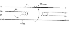
USBケーブルCBL(USB) は、図2に示すように、差動信号(D+),(D−)用の2本の信号線DL1,DL2、並びに電源線VL1および接地線GNDLの4本で構成される。
そして、たとえばホストとしてのパーソナルコンピュータ11とUSB装置12のハブ121を接続するUSBケーブルCBL1を例にとると、図3に示すように、2本の信号線DL1,DL2は、パーソナルコンピュータ11側では、抵抗素子R111,R112を介して接地されており(プルダウンされており)、USB装置12側では、転送速度に応じて、信号線DL1またはDL2のいずれかが抵抗素子R121を介して電源電圧VDDの供給線に接続されている(プルアップされている)。
なお、図3の例では、信号線DL1をプルアップした接続形態を示し、また、電源線VL1および接地線GNDLは省略されている。
【0027】
USB規格では、フルスピードという12Mbpsの転送速度をもつ第1の転送モードと、ロースピードという1.5Mbpsの転送速度をもつ第2の転送モードとがある。
そして、フルスピード、ロースピードの判別は、そのUSBデバイスのアップストリームポートUP1の信号線DL1,DL2のいずれをプルアップするかで決まる。
具体的には、フルスピードのハブやファンクションでは信号線DL1をプルアップし、ロースピードのファンクションでは信号線DL2をプルアップする。
したがって、図3の例の場合、USB装置12側はフルスピードの第1の転送モードであることを上位側であるパーソナルコンピュータ11に報知する接続形態となっている。
この場合、パーソナルコンピュータ11(上位装置)はフルスピードのデータパケットをUSB装置12(下位装置)に転送する。
【0028】
組み込み機能122は、たとえばモニタ13との通信が可能なUSBマイコン123でアクセスされるバッファを有する。
このバッファには、たとえばパーソナルコンピュータ11から転送された通信データが保持される。
【0029】
USBマイコン123は、USB電源124により駆動電力を受けて動作し、USB電源124がオンされた初期化時には、モニタ側のマイコンから、接続ケーブル14を介してUARTのモニタ13の各種データを読み出し、このデータを基に組み込み機能122を有効する。
この初期化時に、モニタ13側から所定時間内に応答がない場合、組み込み機能122を無効にし、ハブ121がいわゆるピュアハブとして動作するように設定する。
また、通常の通信時には、組み込み機能122のバッファに保持される通信データを読み出して、通信の内容をUARTに変換してモニタ13側に送信する。
【0030】
モニタ13は、モニタマイコン131、およびモニタ電源132を有する。
モニタマイコン131は、USB装置12のUSBマイコン123とケーブル14により接続され、UART規格に従ったデータ通信を行う。
また、モニタマイコン131はモニタ電源132により駆動電力を受けて動作し、駆動電力を受けている状態で、かつ、ケーブル14でUSBマイコン123と接続されている場合であって、USBの初期化時にはモニタ13の各種データがUSBマイコン123により読み出される。
【0031】
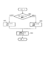
次に、上記構成による動作を、図4に関連付けて説明する。
まず、USB電源124がオンされた初期化時には、USBマイコン123は、モニタ側のマイコンから、UARTのモニタ13の各種データを読み出す動作を始める。すなわち、USBマイコン123はモニタマイコン131と通信を始める(S1)。
このとき、あらかじめ決められた時間内に、UARTの各種データがモニタ13のモニタマイコン131からケーブル14を介して入力されると、USB装置12の組み込み機能122がUSBマイコン123によって有効にされる(S2)。そして、この状態が、ハブ121、USBケーブルCBL1を介してパーソナルコンピュータ11に報知される(S4)。
この場合、パーソナルコンピュータ11からUSBケーブルCBL1を介して転送されたUSB規格に従ったモニタ用通信データは、USB装置12のハブ121を介して組み込み機能122のバッファに保持される。
そして、組み込み機能122のバッファに保持された通信データは、USBマイコン123により読み出されて、通信の内容がUARTに変換されてモニタ13側に送信される。
【0032】
一方、USB電源124がオンされた初期化時に、所定時間が経過してもモニタ13のモニタマイコン131からUARTの各種データが入力されない場合、具体的には、モニタ電源132が立ち上げられていない、あるいは、ケーブル14が接続されていない、あるいは、製品仕様上モニタ13と通信しないため、最初からケーブル14を接続されていない場合等には、USBマイコン123によりUSB装置12の組み込み機能122が無効にされる(S3)。そして、この状態が、ハブ121、USBケーブルCBL1を介してパーソナルコンピュータ11に報知される(S4)。
この場合、USBマイコン123によりハブ121がいわゆるピュアハブとして動作するように設定される。
これにより、モニタマイコン131から応答がない場合であって、USB装置12のUSBマイコン123で自動的に設定変更を行っていることから、システムは正常に動作する。
【0033】
以上説明したように、本第1の実施形態によれば、USB装置12に内蔵の組み込み機能122を使って、パーソナルコンピュータ11からモニタ13を制御するUSBシステムにおいて、初期化時、モニタマイコン131と通信を開始、所定時間内に通信が可能な場合には組み込み機能122を有効にして、その状態をパーソナルコンピュータ11に報知し、所定時間内に通信が不可能な場合には組み込み機能122を無効にして、その状態をパーソナルコンピュータ11に報知するUSBマイコン123を設け、USBマイコン123で自動的に組み込み機能のチェックを行うように構成したことから、マイコン始動までの時間や電源の立ち上がりのタイミングの違い等による初期化時に必要な機能までも動作しなくなるということを防止できる。
また、USBマイコン123が組み込み機能の数量の違うモデルに自動的に対応してくれるため、部品の共通化が図れる利点がある。
【0034】
なお、本第1の実施形態においては、USBマイコン123が初期化時(電源オン時)に、モニタマイコン131との通信を行って、その可否で組み込み機能122を有効また無効にするように構成したが、たとえばUSB電源オン後も定期的にチェックするように構成することも可能である。
この場合、たとえば、USB電源124を立ち上げた後の通常の通信時にも、USBマイコン123のメインルーチン内で定期的にモニタマイコン131との通信を行い、リアルタイムに組み込み機能122の有効/無効を切り換える。
そして、たとえばチェック時に、モニタ電源132がオフまたはオフされた場合、あるいはケーブル14が抜き差しされた場合には、その状況に応じて有効であった組み込み機能122を無効にし、または無効であった組み込み機能122を有効にし、USBマイコン122は、ハブ121、ケーブルCBL1を介して、たとえばケーブル14の抜き差しがあったことをパーソナルコンピュータ11に知らせる。
【0035】
このような構成にすることにより、上述した効果に加えて、実用に即したUSBシステムを実現できる利点がある。
【0036】
第2実施形態
図5は、本発明に係る電子機器システムの第2の実施形態を示すブロック構成図である。
【0037】
本第2の実施形態では、USB装置12Aにおいて、電源設定の自動切り換えを行うとともに、パーソナルコンピュータ11に、USB装置12の設定を再読み込みさせるように構成されている。
【0038】
なお、図5において、図1と同一構成部分は同一符号をもって表している。
すなわち、11はパーソナルコンピュータ、12AはUSB装置、121はUSBハブ、122は組み込み機能、123AはUSBマイコン、125は外部電源検出端子をそれぞれ示している。
また、本第2の実施形態においては、USBケーブルCBL1として、2本の信号線DL1,DL2のみを図示し、電源線VL1および接地線GNDLは省略されている。
また、本第2の実施形態では、USB装置12側で、抵抗素子R121を介して信号線DL1を電源電圧VDDの供給ラインに接続して、信号線DL1をプルアップした接続形態を示している。
すなわち、USB装置12は、フルスピードという12Mbpsの転送速度をもつ第1の転送モードで動作する設定となっている。
【0039】
また、本第2の実施形態においては、信号線DL1と電源電圧VDDの供給ラインとの間のいわゆるプルアップラインに、USBマイコン12Aによりオン・オフが制御されるスイッチとしてのnpn型バイポーラトランジスタQ121が接続されている。
具体的には、トランジスタQ121のコレクタが抵抗素子R121の一端に接続され、エミッタが信号線DL1に接続され、ベースがUSBマイコン12Aの制御信号S12の出力ラインに接続されている。
【0040】
また、USB規格では、デバイスとして、自身で外部電源ユニットを持ち、下位(ダウンストリーム)側に電力を供給可能な自己電源(セルフパワー)デバイスと、自身で外部電源ユニットを持たず、USBケーブルの電源線から電力の供給を受けるバス電源(バスパワー)デバイスがある。
【0041】
そして、本第2の実施形態に係るUSBマイコン123Aは、まず、USB電源オン時に、外部電源検出端子125により、外部電源の有無をチェックし、その旨をハブ121、ケーブルCBL1を介してパーソナルコンピュータ11に報知する。また、電源オン時には、ハイレベルの制御信号S12によりプルアップラインに設けられたスイッチとしてのnpn型トランジスタQ121をオン状態に保持させる。
トランジスタQ121がオンになると、USBケーブルの信号線DL1が電源電圧VDDにプルアップされ、USB装置12Aがフルスピードの第1の転送モードであることが報知される。
また、USB電源オン後も、外部電源検出端子125により、外部電源の有無をチェックしており、たとえば、外部電源、たとえば商用電源から外されて自己電源デバイスからバス電源デバイスに切り換わった場合、設定変更を行うとともに、制御信号S12をローレベルに切り換えて、プルアップラインに設けたられたスイッチとしてのトランジスタQ121を一定時間オフ状態にした後、再度オンさせて(一時的な非通信状態に設定して)、パーソナルコンピュータ11にUSB装置12の各種設定の再読み込みをさせる。
【0042】
次に、上記構成による動作を、図6に関連付けて説明する。
まず、USB電源オン時には、USBマイコン123Aにより、外部電源検出端子125により、外部電源の有無がチェックされる(ST11)。
そして、外部電源がある場合には自己電源デバイスであることが設定され(S12)、外部電源が無い場合にはバス電源デバイスであることが設定され(S13)、他の設定情報とともに、ハブ121、ケーブルCBL1を介してパーソナルコンピュータ11に報知される。
また、電源オン時には、ハイレベルの制御信号S12によりプルアップライントランジスタQ121がオン状態に保持される。
これにより、USBケーブルの信号線DL1が電源電圧VDDにプルアップされ、USB装置12Aがフルスピードの第1の転送モードであることがパーソナルコンピュータ11に報知される。
【0043】
また、USB電源オン後も、USBマイコン123Aにより外部電源検出端子125により、外部電源の有無をチェックされる。そして、たとえば、外部電源、たとえば商用電源から外されて自己電源デバイスからバス電源デバイスに切り換わった場合、設定変更が行われるとともに、制御信号S12がローレベルに切り換えられて、プルアップラインに設けたられたトランジスタQ121が一定時間オフ状態にされた後、再度オンされる。
すなわち、パーソナルコンピュータ11とUSB装置12間の信号ラインを擬似的に一端切断した後に、再接続して、パーソナルコンピュータ11にUSB装置12の各種設定の再読み込みをさせる。
【0044】
本第2の実施形態によれば、外部電源検出端子125により、外部電源の有無をチェックし、たとえば自己電源デバイスからバス電源デバイスに切り換わった場合、設定変更を行うとともに、制御信号S12をローレベルに切り換えて、プルアップラインに設けられたトランジスタQ121を一定時間オフ状態にした後、再度オンさせて、パーソナルコンピュータ11にUSB装置12の各種設定の再読み込みをさせるUSBマイコン123Aを設けたので、ハブの自己電源の状態が変わっても、それをホスト側に知らせることができることから、正しい電源設定ができ、故障を防止できる利点がある。
【0045】
第3実施形態
図7は、本発明に係る電子機器システムの第3の実施形態を示す断面図である。
【0046】
本第3の実施形態では、ホストとしてのパーソナルコンピュータ11にハブ機能を備えたUSB装置では、PS/2マウスを接続可能なUSBキーボード装置15を接続している。
【0047】
USBキーボード装置15は、図7に示すように、USBキーボードファンクション151、USBマウスファンクション152、およびUSBマイコン153を有している。
【0048】
本第3の実施形態では、USBケーブルCBL1として、2本の信号線DL1
,DL2のみを図示し、電源線VL1および接地線GNDLは省略されている。
そして、本第3の実施形態では、USBキーボード装置15側で、抵抗素子R151を介して信号線DL1を電源電圧VDDの供給ラインに接続して、信号線DL1をプルアップした接続形態を示している。
すなわち、USBキーボード装置15は、フルスピードという12Mbpsの転送速度をもつ第1の転送モードで動作する設定となっている。
【0049】
また、本第3の実施形態においては、USBキーボード装置15は、ハブのように、機器の抜き差しを通信によりホスト側に知らせるコマンドがサポートされていないことから、上述した第2の実施形態と同様に、信号線DL1と電源電圧VDDの供給ラインとの間のいわゆるプルアップラインに、USBマイコン15によりオン・オフが制御されるスイッチとしてのnpn型バイポーラトランジスタQ151が接続して、パーソナルコンピュータ11に、USBキーボード装置15の設定を再読み込みさせるように構成されている。
具体的には、トランジスタQ151のコレクタが抵抗素子R151の一端に接続され、エミッタが信号線DL1に接続され、ベースがUSBマイコン15の制御信号S15の出力ラインに接続されている。
【0050】
そして、USBキーボード装置15のUSBマイコン153は、USB電源が投入された後、PS/2ケーブル17を介してマウスマイコン161との通信が行われるか否かの判別を行い、たとえばケーブルが接続されていない等により通信が不可能であると判別した場合には、組み込み機能であるUSBマウスファンクション152を無効に設定し、通信が可能である場合にはUSBマウスファンクション152を有効に設定する。
また、この設定をパーソナルコンピュータ11に再読み込みさせるために、設定変更を行うとともに、制御信号S15をローレベルに切り換えて、プルアップラインに設けたられたスイッチとしてのトランジスタQ151を一定時間オフ状態にした後、再度オンさせて、パーソナルコンピュータ11にUSBキーボード装置15の各種設定の再読み込みをさせる。
【0051】
次に、上記構成による動作を、図8に関連付けて説明する。
まず、USB電源オン後、USBマイコン153により、PS/2ケーブル17を介してマウスマイコン161との通信が行われるか否かの判別が行われる(21)。
ここで、マウスマイコン161から応答があり、通信可能であると判別した場合には、USBマウスファンクション152が有効に設定される(S22)。
一方、たとえばケーブルが接続されていない等により通信が不可能であると判別した場合には、組み込み機能であるUSBマウスファンクション152が無効に設定される(S23)。
そして、設定変更とともに、制御信号S15がローレベルに切り換えられて、プルアップラインに設けられたトランジスタQ151が一定時間オフ状態にされた後、再度オンされる。
すなわち、パーソナルコンピュータ11とUSBキーボード装置15間の信号ラインを擬似的に一端切断した後に、再接続して(一時的な非通信状態に設定して)、パーソナルコンピュータ11にUSBキーボード装置15の各種設定の再読み込みをさせる(S23)。
【0052】
本第3の実施形態によれば、USB電源が投入された後、PS/2ケーブル17を介してマウスマイコン161との通信が行われるか否かの判別を行い、たとえばケーブルが接続されていない等により通信が不可能であると判別した場合には、組み込み機能であるUSBマウスファンクション152を無効に設定し、通信が可能である場合にはUSBマウスファンクション152を有効に設定し、この設定変更とともに、制御信号S15をローレベルに切り換えて、プルアップラインに設けられたスイッチとしてのトランジスタQ151を一定時間オフ状態にした後、再度オンさせて、パーソナルコンピュータ11にUSBキーボード装置15の各種設定の再読み込みをさせるUSBマイコン153を設けたので、マイコン等を介してUSB等以外の異なる通信プロトコルのデバイスを接続する場合、そのデバイスのプラグ&プレイを擬似的に実現することができる。
【0053】
なお、本第3の実施形態では、PS/2マウスが接続されたか否かを例にしてUSBマウスファンクション152の有効・無効を設定するように説明したが、たとえば有効である場合には、マウスマイコン161から読み出されたデータ、たとえばマウスの機能、具体的には4ボタンマウスである、あるいはホイール付きである等の機能データを設定して、パーソナルコンピュータ11にUSBキーボード装置15の各種設定の再読み込みをさせるよう構成することも可能である。
【0054】
【発明の効果】
以上説明したように、本発明によれば、制御回路が自動的に組み込み機能のチェックを行うことから、マイコン始動までの時間や電源の立ち上がりのタイミングの違い等による初期化時に必要な機能までも動作しなくなるということを防止できる。
また、制御回路が組み込み機能の数量の違うモデルに自動的に対応してくれるため、部品の共通化が図れる利点がある。
【0055】
また、マイコン等を介してUSB等以外の異なる通信プロトコルのデバイスを接続する場合、そのデバイスのプラグ&プレイを擬似的に実現することができる。
【0056】
さらに、複数の組み込み機能の電源を個々にオン・オフすることが可能となる。これにより、使わない機能の電源はオフにできるため、省電力化を図ることができる。
【0057】
また、ハブの自己電源の状態が変わっても、それをホスト側に知らせることができることから、正しい電源設定ができ、故障を防止できる利点がある。
【図面の簡単な説明】
【図1】本発明に係る電子機器の第1の実施形態を示すブロック構成図である。
【図2】USBケーブルを説明するための図である。
【図3】USBケーブルの具体的な接続形態を説明するための図である。
【図4】図1の動作を説明するためにフローチャートである。
【図5】本発明に係る電子機器の第2の実施形態を示すブロック構成図である。
【図6】図5の動作を説明するためにフローチャートである。
【図7】本発明に係る電子機器の第2の実施形態を示すブロック構成図である。
【図8】図7の動作を説明するためにフローチャートである。
【符号の説明】
10,10A,10B…電子機器システム、11…パーソナルコンピュータ、12,12A…USB装置、121…ハブ、122…組み込み機能、123,123A…USBマイコン、124…USB電源、125…外部電源検出端子、13…USBハブモニタ、15…USBキーボード装置、151…USBキーボードファンクション、152…USBマウスファンクション、153…USBマイコン、16…PS/2マウス、161…マウスマイコン、CBL1〜CBL6…USBケーブル、DL1,DL2…信号線、VL…電源線、GNDL…接地線。[0001]
BACKGROUND OF THE INVENTION
The present invention relates to an electronic device that transmits and receives information between a host computer and peripheral devices.
[0002]
[Prior art]
In recent years, for example, the USB (Universal Serial Bus) standard has been established as an interface specification for easily connecting a plurality of peripheral devices to a personal computer (host computer), and has come into practical use.
[0003]
This USB can share the interface of peripheral devices such as mouse, keyboard, display, modem, speaker, joystick, etc., which were separate in the past, and supports multiple types and multiple peripheral devices on one bus. Is possible.
Specifically, it is possible to connect up to 127 peripheral devices by simply providing the personal computer main body with one USB terminal.
[0004]
The topology of USB cable connection is branched through a concentrator called a hub. A function (equipment) or a hub can be connected to the lower level of the hub, resulting in a multi-star connection form.
A personal computer is always located at the top.
[0005]
USB peripheral devices can be connected to any USB connector on the system with the power on. Simply plug the connector and the personal computer will determine the type of peripheral device and automatically set the necessary environment settings. Do.
USB also automatically manages the power consumption of connected peripherals, contributing to energy savings for the entire system.
The USB simplifies complicated wiring connections and supports plug and play and hot inserts for connection to external peripheral devices.
[0006]
[Problems to be solved by the invention]
By the way, a communication protocol such as USB can have a function having a plurality of different addresses in one device.
[0007]
Conventionally, however, these functions have been fixed by firmware of a microcomputer (hereinafter referred to as a microcomputer) or setting terminals of an IC.
In other words, even if the state of connection, power supply or the like changes, the specification does not automatically change the setting.
For this reason,likeThere was a problem.
[0008]
(1) In a USB hub with a USB monitor control function, if the USB microcomputer and the monitor microcomputer are not connected, or if the monitor microcomputer is not powered on, the USB hub and built-in functions will operate at initialization. There is a possibility that it will not.
[0009]
(2) In a USB hub having a USB monitor control function, the time from when power is turned on to the USB microcomputer until transmission is started, and the time from when power is turned on to the monitor microcomputer until preparation for reception is completed is omitted. If they are the same, the problem (1) described above may or may not occur.
[0010]
(3) In the USB keyboard with PS / 2 mouse port, physically connect to the USB keyboard.ConnectedA PS / 2 mouse that does not exist appears to exist on the personal computer with which it is communicating.
[0011]
(4) The setting of the USB hub needs to be changed depending on the difference in the power supply circuit, but in reality, the setting does not change due to the presence or absence of an external power supply.
for that reason,TheFor example, a so-called self-powered device using an external power supplyButIf the external power supply is removed halfway after the personal computer recognizes it, the personal computer will not notice that the external power supply is lost and will supply power from the bus.
As a result, the power supply systemInMay cause failure.
[0012]
The present invention has been made in view of such circumstances, and an object of the present invention is to provide an electronic device that can prevent a function that is necessary at the time of initialization from being stopped and that can prevent a failure of a power supply system. is there.
[0013]
[Means for Solving the Problems]
In order to achieve the above object, the present invention provides a host.,andConnection target device controlled by the hostIs connectedAn electronic device that is connected to the hostWhen the initialization changes from the non-communication state to the communication state, the host reads various settings for the device connected to the electronic device.Port,Through the above portsFrom the above hostTo the above connection target deviceTransferred communication dataTheRetentionDoBuilt-in functions including a buffer and the above connection target machine at initializationWith vesselcommunicationTry, When communication is possible within a predetermined timeIs onEnable the built-in functionSet and placeCommunication within a fixed timeNot possibleIf you disable the built-in features aboveSetting systemControl circuitThe control circuit, after changing the setting of valid / invalid for the built-in function, temporarily sets the communication state between the port and the host to a non-communication state, by the host, Various settings of the device connected to the electronic device including the setting of the connection target device set to be valid are re-read.
[0014]
Also,Preferably,The control circuit isDuring normal communication in which the built-in function is valid, the communication data transferred from the host is held in the buffer of the built-in function, the communication data is read, the communication content is converted into the predetermined protocol, and the connection target device Send to.
[0015]
Also,Preferably,The control circuit isEven during normal communication, communication with the connection target device is performed periodically, and the built-in function is enabled / disabled depending on whether communication is possible within a predetermined time..
[0018]
Also,Preferably,The control circuit isInforms the host whether the first transfer mode at full speed and the second transfer mode at low speed are used, and causes the host to transfer data in the transfer mode informed to the host..
[0019]
According to the present invention, the state of each built-in function is detected in the control circuit. In the control circuit, when the state of each function is detected and the state is changed, the state of the function is changed according to the detection result.
In addition, the control circuit notifies the host of the state of each set function. Thus, the system is controlled by the host side based on the notified information.
Note that the control circuit notifies that the setting of the function state has been changed by temporarily setting the communication line connected to the host to a specific state regardless of the command.
When a temporary specific state is detected on the host side, the setting information of the state of each function is reloaded, and the system is controlled based on the reloaded information.
[0020]
Further, according to the present invention, the communication data received from the host side is converted into a communication protocol different from the communication protocol with the host by the control circuit, and transmitted to another device corresponding to the predetermined function. .
Further, at the time of initialization or the like, it is determined whether or not communication with another device is possible, and the state of the corresponding function is detected.
If it is determined that communication is possible, the corresponding function is set as valid, and if it is determined that communication is not possible, the corresponding device is set as invalid. Is done.
When the control circuit determines that communication with another device is possible, the specification information of the other device is read and the information is notified to the host side.
[0021]
DETAILED DESCRIPTION OF THE INVENTION
First embodiment
FIG. 1 is a block diagram showing a first embodiment of an electronic device system according to the present invention.
In the first embodiment, a USB system is shown as an example of the electronic device system.
[0022]
As shown in FIG. 1, the
[0023]
The
The
[0024]
The
[0025]
The
Also, the remaining downstream port DN2-DN5 can be connected to a USB device such as a printer (not shown) via USB cables CBL3 to CBL6.
[0026]
USB cable CBL(USB)As shown in FIG. 2, it is composed of two signal lines DL1 and DL2 for differential signals (D +) and (D-), and four lines of a power supply line VL1 and a ground line GNDL.
For example, taking the USB cable CBL1 connecting the
In the example of FIG. 3, a connection form in which the signal line DL1 is pulled up is shown, and the power supply line VL1 and the ground line GNDL are omitted.
[0027]
In the USB standard, there are a first transfer mode having a transfer speed of 12 Mbps, which is full speed, and a second transfer mode having a transfer speed of 1.5 Mbps, which is low speed.
The discrimination between full speed and low speed is determined by which of the signal lines DL1 and DL2 of the upstream port UP1 of the USB device is pulled up.
Specifically, the signal line DL1 is pulled up in a full speed hub or function, and the signal line DL2 is pulled up in a low speed function.
Therefore, in the case of the example of FIG. 3, the
In this case, the personal computer 11 (high-order device) transfers the full-speed data packet to the USB device 12 (low-order device).
[0028]
The built-in
For example, communication data transferred from the
[0029]
The
When there is no response within a predetermined time from the
Further, during normal communication, the communication data held in the buffer of the built-in
[0030]
The
The
Further, the
[0031]
Next, the operation of the above configuration will be described with reference to FIG.
First, at initialization when the
At this time, if various types of UART data are input from the
In this case, the monitor communication data according to the USB standard transferred from the
The communication data held in the buffer of the built-in
[0032]
On the other hand, when various types of UART data are not input from the
In this case, the
As a result, even if there is no response from the
[0033]
As described above, according to the first embodiment, in the USB system that controls the
In addition, since the
[0034]
In the first embodiment, the
In this case, for example, even during normal communication after starting up the
For example, when the
[0035]
With such a configuration, in addition to the effects described above, there is an advantage that a USB system suitable for practical use can be realized.
[0036]
Second embodiment
FIG. 5 is a block diagram showing a second embodiment of the electronic device system according to the present invention.
[0037]
In the second embodiment, the
[0038]
In FIG. 5, the same components as those in FIG. 1 are denoted by the same reference numerals.
That is, 11 is a personal computer, 12A is a USB device, 121 is a USB hub, 122 is a built-in function, 123A is a USB microcomputer, and 125 is an external power supply detection terminal.
In the second embodiment, only two signal lines DL1 and DL2 are shown as the USB cable CBL1, and the power supply line VL1 and the ground line GNDL are omitted.
In the second embodiment, the signal line DL1 is connected to the power supply voltage V via the resistance element R121 on the
That is, the
[0039]
In the second embodiment, the signal line DL1 and the power supply voltage VDDAn npn-type bipolar transistor Q121 as a switch that is controlled to be turned on / off by the
Specifically, the collector of the transistor Q121 is connected to one end of the resistor element R121, the emitter is connected to the signal line DL1, and the base is connected to the output line of the control signal S12 of the
[0040]
Also, in the USB standard, as a device, a self-powered device that has its own external power supply unit and can supply power to the lower side (downstream), and a USB cable that does not have its own external power supply unit. There is a bus power supply device that receives power from a power line.
[0041]
Then, the
When the transistor Q121 is turned on, the signal line DL1 of the USB cable is connected to the power supply voltage VDDTo notify that the
In addition, even after the USB power is turned on, the presence or absence of an external power supply is checked by the external power supply detection terminal 125.For example, when the external power supply, for example, the commercial power supply is disconnected and the self power supply device is switched to the bus power supply device, In addition to changing the setting, the control signal S12 is switched to a low level to turn off the transistor Q121 as a switch provided in the pull-up line for a certain period of time, and then turn it on again (to temporarily enter a non-communication state). After setting), the
[0042]
Next, the operation of the above configuration will be described with reference to FIG.
First, when the USB power is turned on, the presence or absence of an external power source is checked by the external
When there is an external power supply, it is set as a self-power supply device (S12), and when there is no external power supply, it is set as a bus power supply device (S13). Together with other setting information, the
When the power is turned on, the pull-up line transistor Q121 is held in the on state by the high level control signal S12.
As a result, the signal line DL1 of the USB cable is connected to the power supply voltage V.DDTo inform the
[0043]
Further, even after the USB power is turned on, the presence or absence of the external power supply is checked by the external
That is, the signal line between the
[0044]
According to the second embodiment, the presence / absence of an external power supply is checked by the external power
[0045]
Third embodiment
FIG. 7 is a cross-sectional view showing a third embodiment of the electronic device system according to the present invention.
[0046]
In the third embodiment, a
[0047]
As shown in FIG. 7, the
[0048]
In the third embodiment, two signal lines DL1 are used as the USB cable CBL1.
, DL2 only is shown, and the power supply line VL1 and the ground line GNDL are omitted.
In the third embodiment, the signal line DL1 is connected to the power supply voltage V via the resistance element R151 on the
That is, the
[0049]
Further, in the third embodiment, the
Specifically, the collector of the transistor Q151 is connected to one end of the resistance element R151, the emitter is connected to the signal line DL1, and the base is connected to the output line of the control signal S15 of the
[0050]
The
Further, in order to cause the
[0051]
Next, the operation of the above configuration will be described with reference to FIG.
First, after the USB power is turned on, the
If it is determined that there is a response from the
On the other hand, if it is determined that communication is not possible, for example, because the cable is not connected, the
Then, along with the setting change, the control signal S15 is switched to the low level, and the transistor Q151 provided in the pull-up line is turned off for a predetermined time, and then turned on again.
That is, the signal line between the
[0052]
According to the third embodiment, after the USB power is turned on, it is determined whether or not communication with the
[0053]
In the third embodiment, whether or not a PS / 2 mouse is connected is determined.As an exampleThe
[0054]
【The invention's effect】
As described above, according to the present invention, since the control circuit automatically checks the built-in function, even the functions required at the time of initialization due to differences in the time until the microcomputer starts up and the timing of the power supply startup, etc. It can prevent that it does not operate.
In addition, since the control circuit automatically supports models with different numbers of built-in functions, there is an advantage that parts can be shared.
[0055]
Further, when a device with a different communication protocol other than USB or the like is connected via a microcomputer or the like, plug-and-play of the device can be realized in a pseudo manner.
[0056]
Furthermore, it becomes possible to individually turn on / off the power supplies of a plurality of built-in functions. As a result, power of functions not used can be turned off, so that power saving can be achieved.
[0057]
In addition, even if the hub's self-power supply state changes, it can be notified to the host side, so there is an advantage that correct power supply setting can be performed and failure can be prevented.
[Brief description of the drawings]
FIG. 1 is a block configuration diagram showing a first embodiment of an electronic apparatus according to the invention.
FIG. 2 is a diagram for explaining a USB cable.
FIG. 3 is a diagram for explaining a specific connection form of a USB cable.
FIG. 4 is a flowchart for explaining the operation of FIG. 1;
FIG. 5 is a block configuration diagram showing a second embodiment of the electronic apparatus according to the invention.
FIG. 6 is a flowchart for explaining the operation of FIG. 5;
FIG. 7 is a block configuration diagram showing a second embodiment of an electronic apparatus according to the invention.
FIG. 8 is a flowchart for explaining the operation of FIG. 7;
[Explanation of symbols]
DESCRIPTION OF
Claims (4)
上記ホストが接続され、初期化によって非通信状態から通信状態になると上記ホストにより当該電子機器に接続されている機器についての各種設定が読み込まれるポートと、
上記ポートを通じて上記ホストから上記接続対象機器宛てに転送された通信データを保持するバッファを含む組み込み機能と、
初期化時、上記接続対象機器との通信を試み、所定時間内に通信が可能な場合には上記組み込み機能を有効に設定し、所定時間内に通信が可能にならない場合には上記組み込み機能を無効に設定する制御回路と
を有し、
上記制御回路は、
上記組み込み機能についての有効無効の設定の変更を行った後、上記ポートと上記ホストとの通信状態を一時的に非通信状態に設定し、上記ホストにより、有効に設定された上記接続対象機器の設定を含む、当該電子機器に接続された機器の各種設定を再読み込みさせる
電子機器。 An electronic device to which a host and a connection target device controlled by the host are connected ,
When the host is connected and when it is changed from a non-communication state to a communication state by initialization, a port from which various settings about the device connected to the electronic device are read by the host ;
A built-in features including a buffer for holding the communication data transferred to the connected device addressed to said host through said port,
At initialization, the if the connection attempt to communicate with the target equipment, which is not on the Symbol built effectively function set, it can communicate within Jo Tokoro time if possible to communicate within a predetermined time and a control circuit to disable the built-in functionality
Have
The control circuit is
After changing the valid / invalid setting for the built-in function, the communication state between the port and the host is temporarily set to a non-communication state, and the connection target device that has been set valid by the host is set. An electronic device that reloads various settings of a device connected to the electronic device, including settings .
上記組み込み機能が有効な通常の通信時には、上記ホストから転送された通信データが上記組み込み機能のバッファに保持され、当該通信データを読み出し、通信内容を所定のプロトコルに変換して上記接続対象機器に送信する
請求項1記載の電子機器。The control circuit is
The integration in the time available normal communication function, the communication data transferred from the host is stored in the buffer of the built-in function, it reads the communication data, converts the communication contents to a Jo Tokoro protocol the connected device The electronic device according to claim 1.
通常の通信時にも、定期的に上記接続対象機器との通信を行い、所定時間内に通信が可能か否かに応じて、上記組み込み機能を有効、無効の設定を行う
請求項1または2記載の電子機器。The control circuit is
The communication with the connection target device is periodically performed even during normal communication, and the built-in function is set to be valid or invalid depending on whether communication is possible within a predetermined time. Electronic equipment.
フルスピードの第1の転送モードと、ロースピードの第2の転送モードであるかを上記ホストに報知し、上記ホストに報知した転送モードでデータを転送させる
請求項1から3のいずれか一に記載の電子機器。The control circuit is
A first transfer mode for full speed, whether the second transfer mode for low-speed informed to the host, any one of claims 1-3 for transferring data transfer mode notified to the host The electronic device described.
Priority Applications (1)
| Application Number | Priority Date | Filing Date | Title |
|---|---|---|---|
| JP13563299A JP4524812B2 (en) | 1999-05-17 | 1999-05-17 | Electronics |
Applications Claiming Priority (1)
| Application Number | Priority Date | Filing Date | Title |
|---|---|---|---|
| JP13563299A JP4524812B2 (en) | 1999-05-17 | 1999-05-17 | Electronics |
Publications (3)
| Publication Number | Publication Date |
|---|---|
| JP2000330926A JP2000330926A (en) | 2000-11-30 |
| JP2000330926A5 JP2000330926A5 (en) | 2006-04-13 |
| JP4524812B2 true JP4524812B2 (en) | 2010-08-18 |
Family
ID=15156356
Family Applications (1)
| Application Number | Title | Priority Date | Filing Date |
|---|---|---|---|
| JP13563299A Expired - Fee Related JP4524812B2 (en) | 1999-05-17 | 1999-05-17 | Electronics |
Country Status (1)
| Country | Link |
|---|---|
| JP (1) | JP4524812B2 (en) |
Families Citing this family (6)
| Publication number | Priority date | Publication date | Assignee | Title |
|---|---|---|---|---|
| EP1183611B1 (en) * | 1999-12-24 | 2007-03-14 | Koninklijke Philips Electronics N.V. | Emulation of a disconnect of a device |
| JP4697826B2 (en) * | 2001-01-26 | 2011-06-08 | フィガロ技研株式会社 | Gas detection system and gas detection method |
| JP4258264B2 (en) * | 2003-04-24 | 2009-04-30 | セイコーエプソン株式会社 | Information terminal device and POS terminal equipped with the same |
| JP4529441B2 (en) * | 2004-01-05 | 2010-08-25 | 富士ゼロックス株式会社 | Image processing apparatus and host apparatus |
| JP2007156921A (en) * | 2005-12-06 | 2007-06-21 | Y E Data Inc | Failure detection/recovery system of usb device, program thereof, recording medium with the program recorded thereon, and failure detection/recovery method |
| JP2008225993A (en) * | 2007-03-14 | 2008-09-25 | Pfu Ltd | Power supply control circuit and scanner device |
Citations (5)
| Publication number | Priority date | Publication date | Assignee | Title |
|---|---|---|---|---|
| JPH10187303A (en) * | 1996-11-07 | 1998-07-14 | Hitachi Ltd | Interface switching device and method for controlling interface switching and keyboard |
| JPH10326251A (en) * | 1997-05-01 | 1998-12-08 | Smc Standard Microsyst Corp | Usb peripheral microcontroller |
| WO1999001820A1 (en) * | 1997-07-02 | 1999-01-14 | Cypress Semiconductor Corporation | Bus interface system and method |
| JPH1185666A (en) * | 1997-09-02 | 1999-03-30 | Fuji Electric Co Ltd | Integrated circuit communication control |
| JPH1193916A (en) * | 1997-09-19 | 1999-04-06 | Koganei Corp | Fluid pressure system and system apparatus |
-
1999
- 1999-05-17 JP JP13563299A patent/JP4524812B2/en not_active Expired - Fee Related
Patent Citations (5)
| Publication number | Priority date | Publication date | Assignee | Title |
|---|---|---|---|---|
| JPH10187303A (en) * | 1996-11-07 | 1998-07-14 | Hitachi Ltd | Interface switching device and method for controlling interface switching and keyboard |
| JPH10326251A (en) * | 1997-05-01 | 1998-12-08 | Smc Standard Microsyst Corp | Usb peripheral microcontroller |
| WO1999001820A1 (en) * | 1997-07-02 | 1999-01-14 | Cypress Semiconductor Corporation | Bus interface system and method |
| JPH1185666A (en) * | 1997-09-02 | 1999-03-30 | Fuji Electric Co Ltd | Integrated circuit communication control |
| JPH1193916A (en) * | 1997-09-19 | 1999-04-06 | Koganei Corp | Fluid pressure system and system apparatus |
Also Published As
| Publication number | Publication date |
|---|---|
| JP2000330926A (en) | 2000-11-30 |
Similar Documents
| Publication | Publication Date | Title |
|---|---|---|
| JP4126178B2 (en) | Method and apparatus for detecting the type of interface to which a peripheral device is connected | |
| US5457785A (en) | CPU-independent and device-driver transparent system for translating a computer's internal bus signals onto an intermediate bus and further translating onto an expansion bus | |
| US7765344B2 (en) | Apparatus and method for dynamically providing hub or host operations | |
| WO2009091193A2 (en) | Mobile terminal for supporting uart communication and usb communication using single connector and operating method for same | |
| US8055919B2 (en) | Port power controller for USB hubs with legacy battery charge support | |
| US6601124B1 (en) | Universal interface for selectively coupling to a computer port type and method therefor | |
| JP3610424B2 (en) | Electronic equipment and interface circuit | |
| US6845420B2 (en) | System for supporting both serial and parallel storage devices on a connector | |
| US7895386B2 (en) | USB interface provided with host/device function and its control method | |
| US5935224A (en) | Method and apparatus for adaptively coupling an external peripheral device to either a universal serial bus port on a computer or hub or a game port on a computer | |
| JP3838278B2 (en) | Bridge circuit between two buses of a computer system | |
| CA2297084C (en) | A universal serial bus device controller | |
| US5784581A (en) | Apparatus and method for operating a peripheral device as either a master device or a slave device | |
| US20060106962A1 (en) | USB On-The-Go implementation | |
| US5613074A (en) | Automatic disabling of SCSI bus terminators | |
| US6775733B2 (en) | Interface for USB host controller and root hub | |
| US5680555A (en) | Host adapter providing automatic terminator configuration | |
| US6185642B1 (en) | Bus for high frequency operation with backward compatibility and hot-plug ability | |
| US20040200631A1 (en) | Cable and connection module for a universal serial bus interface | |
| JP2000056871A (en) | Ems enhancement circuit for usb system | |
| WO2001025942A1 (en) | Method and apparatus for detecting the type of interface to which a peripheral device is connected | |
| JP2002149284A (en) | Storage apparatus | |
| WO2000073891A1 (en) | Method and apparatus for maintaining load balance on a graphics bus when an upgrade device is installed | |
| JP4524812B2 (en) | Electronics | |
| JP2002297275A (en) | Data transferring device and computer device and device and docking station |
Legal Events
| Date | Code | Title | Description |
|---|---|---|---|
| A521 | Written amendment |
Free format text: JAPANESE INTERMEDIATE CODE: A523 Effective date: 20060224 |
|
| A621 | Written request for application examination |
Free format text: JAPANESE INTERMEDIATE CODE: A621 Effective date: 20060224 |
|
| A977 | Report on retrieval |
Free format text: JAPANESE INTERMEDIATE CODE: A971007 Effective date: 20081128 |
|
| A131 | Notification of reasons for refusal |
Free format text: JAPANESE INTERMEDIATE CODE: A131 Effective date: 20090106 |
|
| A521 | Written amendment |
Free format text: JAPANESE INTERMEDIATE CODE: A523 Effective date: 20090309 |
|
| A131 | Notification of reasons for refusal |
Free format text: JAPANESE INTERMEDIATE CODE: A131 Effective date: 20091013 |
|
| A521 | Written amendment |
Free format text: JAPANESE INTERMEDIATE CODE: A523 Effective date: 20091203 |
|
| TRDD | Decision of grant or rejection written | ||
| A01 | Written decision to grant a patent or to grant a registration (utility model) |
Free format text: JAPANESE INTERMEDIATE CODE: A01 Effective date: 20100511 |
|
| A01 | Written decision to grant a patent or to grant a registration (utility model) |
Free format text: JAPANESE INTERMEDIATE CODE: A01 |
|
| A61 | First payment of annual fees (during grant procedure) |
Free format text: JAPANESE INTERMEDIATE CODE: A61 Effective date: 20100524 |
|
| FPAY | Renewal fee payment (event date is renewal date of database) |
Free format text: PAYMENT UNTIL: 20130611 Year of fee payment: 3 |
|
| FPAY | Renewal fee payment (event date is renewal date of database) |
Free format text: PAYMENT UNTIL: 20130611 Year of fee payment: 3 |
|
| A521 | Written amendment |
Free format text: JAPANESE INTERMEDIATE CODE: A523 Effective date: 20060224 |
|
| LAPS | Cancellation because of no payment of annual fees |