JP4523748B2 - Heat treatment method and apparatus for photosensitive element - Google Patents
Heat treatment method and apparatus for photosensitive element Download PDFInfo
- Publication number
- JP4523748B2 JP4523748B2 JP2001522138A JP2001522138A JP4523748B2 JP 4523748 B2 JP4523748 B2 JP 4523748B2 JP 2001522138 A JP2001522138 A JP 2001522138A JP 2001522138 A JP2001522138 A JP 2001522138A JP 4523748 B2 JP4523748 B2 JP 4523748B2
- Authority
- JP
- Japan
- Prior art keywords
- temperature
- drum
- layer
- composition layer
- roller
- Prior art date
- Legal status (The legal status is an assumption and is not a legal conclusion. Google has not performed a legal analysis and makes no representation as to the accuracy of the status listed.)
- Expired - Lifetime
Links
Images


Classifications
-
- G—PHYSICS
- G03—PHOTOGRAPHY; CINEMATOGRAPHY; ANALOGOUS TECHNIQUES USING WAVES OTHER THAN OPTICAL WAVES; ELECTROGRAPHY; HOLOGRAPHY
- G03F—PHOTOMECHANICAL PRODUCTION OF TEXTURED OR PATTERNED SURFACES, e.g. FOR PRINTING, FOR PROCESSING OF SEMICONDUCTOR DEVICES; MATERIALS THEREFOR; ORIGINALS THEREFOR; APPARATUS SPECIALLY ADAPTED THEREFOR
- G03F7/00—Photomechanical, e.g. photolithographic, production of textured or patterned surfaces, e.g. printing surfaces; Materials therefor, e.g. comprising photoresists; Apparatus specially adapted therefor
- G03F7/26—Processing photosensitive materials; Apparatus therefor
- G03F7/36—Imagewise removal not covered by groups G03F7/30 - G03F7/34, e.g. using gas streams, using plasma
-
- G—PHYSICS
- G03—PHOTOGRAPHY; CINEMATOGRAPHY; ANALOGOUS TECHNIQUES USING WAVES OTHER THAN OPTICAL WAVES; ELECTROGRAPHY; HOLOGRAPHY
- G03F—PHOTOMECHANICAL PRODUCTION OF TEXTURED OR PATTERNED SURFACES, e.g. FOR PRINTING, FOR PROCESSING OF SEMICONDUCTOR DEVICES; MATERIALS THEREFOR; ORIGINALS THEREFOR; APPARATUS SPECIALLY ADAPTED THEREFOR
- G03F7/00—Photomechanical, e.g. photolithographic, production of textured or patterned surfaces, e.g. printing surfaces; Materials therefor, e.g. comprising photoresists; Apparatus specially adapted therefor
- G03F7/26—Processing photosensitive materials; Apparatus therefor
- G03F7/34—Imagewise removal by selective transfer, e.g. peeling away
- G03F7/343—Lamination or delamination methods or apparatus for photolitographic photosensitive material
Landscapes
- Physics & Mathematics (AREA)
- General Physics & Mathematics (AREA)
- Photosensitive Polymer And Photoresist Processing (AREA)
Description
【0001】
(背景技術)
本発明は、溶剤を用いることなく熱処理を利用してレリーフパターンを形成する感光性要素の処理方法および装置に関し、特に、フレキソ印刷版を形成するための感光性要素の熱現像方法および装置に関する。
【0002】
米国特許第3,060,023号において、Burgらは、乾式熱処理を用いて光重合された画像担持要素から受容表面に画像を転写する方法を開示している。光重合可能層を備えたフィルム支持体は、溶融しない露出領域と、溶融すると共に画像受容要素に転移可能な露出不足領域とを提供するように画像に露出される。多数の例において、紙の画像受容要素がフィルム支持体の層表面に接触するように配置され、集合体を加熱すべくフィルム支持体を押圧する高温の平坦な加熱要素によって熱が加えられる。幾つかの例では、加熱されない集合体が、一方が加熱された2体のローラ間を通過させられる。紙は、なお温かいうちに層から剥がされ、紙要素への層の露出されていない物質の転写がもたらされる。熱転写処理を繰り返すことにより、紙への画像の多重コピーが達成される。少数の例では、紙を加熱すると共に層に密接するように押圧することによって熱転写が実現される。「…熱は、少なくとも光重合可能層の軟化温度に対応した転写温度に供された要素の何れかまたは双方への分離工程に先立つ何れかの段階で加えられ得る。例えば、ローラ、平坦なまたは湾曲した加熱表面すなわちプラテン、例えばヒートランプのような放射源といったその分野においてよく知られた手段によって、熱が加えられ得る。」という説明以上の示唆はなされていない。加熱時間は、その例では、0.5〜10秒の間で変化させられている。標準的なフィルム厚さは、1〜4ミル(およそ0.025〜0.1mm)であり、層の厚さは、0.5〜4ミル(およそ0.013〜0.1mm)である。少数の例では、層にレリーフ画像を持ったフィルム支持体が、更に化学線の光により処理され得ると共にコピーをとるために輪転機での印刷に使用され得る、と開示されている。
【0003】
Martensに付与された米国特許第5,175,072号は、照射硬化性組成物を可撓性基材上に層として用意し、照射領域において組成物が硬化するように当該組成物を画像に応じて照射し、組成物層を40〜200℃の温度まで加熱し、照射されていない層を軟化させ、流動可能な軟化した非照射領域を吸収することができる吸収層に組成物層を接触させると共にその吸収層を取り除き、それによって吸収された流動可能な組成物を可撓性基材上の組成物の非照射領域から除去することにより、フレキソ印刷版を製造する熱処理法を開示している。これにより、基材の背後に、照射された画像を表わす照射されて硬化した組成物の浮き上がったレリーフ構造が残される。このレリーフ領域は、印刷工程におけるインキングロールからのインクを受容すると共に印刷作業中にインクを印刷基材に転写するインク受容表面となる。また、この方法は、基材上の硬化した組成物の「フロア」をまず現像することにより、照射されて硬化した組成物の可撓性基材への接着度を改善することができる予備現像工程を利用し得る。これは、可撓性基材に隣接する組成物層を重合させるように可撓性基材を介して電離放射線を送ることにより実現される。この層は、画像の現像および非照射組成物の除去の間に除去されることはない。
【0004】
加熱処理の間、可撓性基材、組成物層および吸収層からなる積層体は、ポリエステルフィルムである可撓性基材がプラテンと接触する状態で、それらを加熱されたプラテンに載置することによって加熱される。吸収層は、不織ナイロンウェブからなる。積層体がおよそ135℃のプラテン温度と平衡を保つことができるようにするための数秒間のウォームアップ時間の後、積層体は、ゴムで覆われており、およそ30cm/分の回転速度で逆方向に回転する2体の加熱されたニップロール間に通される。ロール同士の間には、積層体がギャップに挿入された際にそれが軽く圧縮されるように隙間が開けられている。積層体がニップロール間から出ると、吸収層は、加熱された組成物の表面から一定の張力によって持ち上げられる。組成物の非照射領域は、不織ウェブへの吸収により取り除かれる。加熱および押圧工程は、非照射領域から少なくとも75%の照射されていない組成物が取り除かれるまで数回繰り返される。可撓性基材および照射されて硬化した組成物は、非照射組成物を取り除くのに必要とされる上昇させられた温度において安定であることが望ましく、その結果、可撓性基材および硬化した組成物が何れの表面寸法においても2%以上歪まない。
【0005】
Petersonらに付与された米国特許第5,279,697号は、照射された印刷要素を取り扱うと共に、要素から非照射組成物を取り除くように繰り返される加熱および押圧を実現する自動化された方法および装置を開示している。可撓性フィルム基材および組成物層からなり、照射および非照射領域を備えた要素は、その主壁の内面に配置された電気加熱ブランケットによって加熱される予熱ドラム上に配置される。熱は、ドラムの壁部を通し、可撓性基材を通して伝わり、非照射領域の融点近傍の温度に組成物層を予熱するであろう。
【0006】
不織ナイロンウェブの吸収層の連続シートは、供給ロールから引き出され、ウェブを加熱する高温ロール上に通される。高温ロールは、予熱ドラムに向けて付勢され、それにより、予熱ヒータ上の印刷要素の予熱された組成物層に対して加熱されたウェブを押圧する。吸収ウェブの熱は、組成物層の非照射部が液化すると共に不織ウェブの吸収層に吸収されることを可能にするのに十分な温度まで可撓性フィルムの温度が高められるように、接触時に印刷要素に伝えられる。高温ロールは、電気コアヒータや、可撓性フィルム上の組成物の部分を溶解させるのに十分な温度を提供すべく蒸気、油、高温エア等を用いるであろう他の手段によって加熱されてもよい。予熱ドラムおよび高温ロールが共に接触しながら回転すると、ウェブは、液化させられた非照射組成物を吸収するように印刷要素に対して押圧されると共に、印刷要素から引き離され、それにより、印刷要素から吸収された組成物を分離させる。ウェブは、高温ロールから離れるように移送され、無駄を除くため、または、リサイクルのために巻き戻される。印刷要素から非照射組成物の大部分を漸次除去すべく、印刷要素を高温ロールに数サイクル通過させることが繰り返される。非照射組成物が取り除かれると、印刷処理に好適な硬化した照射領域の浮き上がったレリーフをもった刷版が生じる。場合によっては、残留したいかなる非照射組成物をも硬化させるべく、印刷要素の最終的照射が行われる。
【0007】
上述されたBurgら、Martens、および、Petersonらの方法および装置における共通のプラクティスは、非照射組成物の融点近傍の温度までフィルム基材を加熱することである。しかしながら、フィルム基材を加熱することは、印刷の間に現れる刷版のレリーフ領域の品質に影響を及ぼす程度にまで基材を歪ませてしまうであろう。フィルム基材の温度は加熱および吸収サイクルを繰り返すたびに徐々に増加し、最終サイクルまでには、フィルム基材は、ほぼ非照射組成物の融点に達するのが一般的である。基材の歪みによって引き起こされる問題は、3色または4色の印刷処理のためには、異なる色が集まって正確な最終画像をつくり出すように正しく重なり合った画像により3枚または4枚の刷版がつくり出されていなければならない、ということである。仮に、何れか1枚の刷版が一方向に歪んでおり、他の刷版が他の方向に歪んでいると、良質のカラープリントをつくり出すように正確に見当が合わなくなるであろう。基材は加熱されると収縮する特性を有しており、製造順序によりxおよびy平面方向において不均一となるのが一般的である。基材は、一般に、製造の幅方向よりも長さ方向に収縮する。刷版の現像の間に基材が遭遇する温度では0.1%の基材収縮が許容し得る最大であり、高品質の多版カラー印刷のためには、収縮は、0,02%を超えないことが好ましい。また、基材収縮は、完成した感光性要素にしわが表出しないように、基材上にコートされた組成物と適合していなければならない。感光性要素の熱画像処理に要求される温度で低い収縮性を有している基材を提供することは困難である。
【0008】
Burgらの方法において、フィルムおよび層の厚さは、頑丈な刷版にとって一般に薄すぎるものであり、厚く頑丈で商業用途に適した刷版を高速で製造するための方法または装置は教示されていない。Burgらのものは紙のみを加熱するが、この処理は、紙上に画像をつくり出すのに不可欠である少量の層のみを取り除くだけである。
【0009】
Petersonらにより開示された形式の改良された方法および装置であって、可撓性フィルム基材の不要な加熱を制限しながら、組成物層を十分な厚さにわたって要求される温度まで急速に加熱する方法および装置へのニーズが存在している。加熱および吸収の各サイクルによる可撓性フィルムの熱の蓄積を制御する必要もある。
【0010】
(発明の概要)
本発明は、組成物層の非照射領域の溶融温度に可撓性基材上の組成物層を加熱すること、なお高温の組成物層に加熱された吸収層を押圧しながら、組成物層の非照射領域の溶融温度を下回る温度に可撓性基材を維持すること、および、これらのステップを多サイクル繰り返す方法に係る。この方法の更なる形態は、加熱された組成物層の温度を下回る所望温度に可撓性基材を維持するために、可撓性基材および層積層体を冷却するステップを含む。
【0011】
本発明は、レリーフパターン、特に、外側表面および内側表面を有する可撓性基材と、外側表面および内側表面を有し、部分的に液化可能である可撓性基材上の組成物層とを備え、組成物層と可撓性基材とがそれぞれの内側表面で接合されている感光性要素からフレキソ印刷版を形成する装置に係り、第1のフレーム部に回転するように取り付けられており、組成物層の外側表面に吸収材を供給するローラと、第2のフレーム部に回転するように取り付けられており、ドラム外周面と可撓性基材の外側表面とが接触する状態で感光性要素をドラム外周面に支持する手段を有し、感光性要素を吸収材に搬送するように位置決めされているドラムであって、第1および第2のフレーム部の少なくとも一方が他方に対して相対的に移動可能となっているドラムと、吸収材がローラにおいて層と接触する箇所に近接しているドラム上の組成物層の外側表面に熱を加え、層の一部を液化させるのに十分な温度T2以上の温度T1に層の外側表面を加熱する一方、温度T1を少なくともおよそ11.1℃(華氏で20度)下回る温度T3に可撓性基材の外側表面を維持するように適合されている第1の加熱手段と、吸収材が層の外側表面と接触する状態で、温度T2以上の温度T4に組成物層の外側表面を加熱することができる温度にローラを加熱する一方、温度T4を少なくともおよそ11.1℃(華氏で20度)下回る温度T3に可撓性基材の外側表面を維持するように適合されている第2の加熱手段と、組成物層の液化した物質の少なくとも一部が吸収材によって吸収されるのに十分な圧力で、感光性要素と吸収材とをドラムとローラとの間で接触させる加圧手段と、感光性要素を吸収材から分離させる分離手段とを備える。
【0012】
この装置の更なる形態は、吸収材から要素が分離される箇所で感光性要素を冷却する強制冷却手段を含んでいる。
【0013】
(好ましい実施形態の詳細な説明)
本発明は、感光性要素を熱現像するための装置および方法に係る。本発明の装置は、感光性要素の熱現像、好ましくは、フレキソ印刷版の形成には限定されない。本発明は、部分的に液化され得る組成物の層を有する感光性要素を何れかの目的のためにその層の少なくとも一部を溶融させるのに十分な温度まで加熱することができる装置を意図している。そのような目的の更なるものは、流体制御装置での使用のために流体回路を形成するラミネート処理において使用される表面に流体チャネルのレリーフパターンを形成するということである。
【0014】
感光性要素は、可撓性基材および該基材上に配された組成物層とを含み、組成物層は、部分的に液化され得る基材上の少なくとも1つの層を構成する。好ましくは、感光性要素は、フレキソ印刷版として用いるのに適したエラストマ系印刷要素である。基材上の少なくとも1つの層は、好ましくは、感光層であり、最も好ましくは、感光層が化学線によって選択的に硬化されるエラストマ系組成物からなる光重合可能層である。ここで用いられる場合、「光重合可能」という用語は、光重合可能、光架橋可能、または双方の体系をも包含する。組成物層が1つ以上の可撓性基材上の感光層からなる場合、感光層の組成物のそれぞれは、他の感光層のいずれかと同一であってもよく、異なっていてもよい。
【0015】
限定はされないが、エラストマ系組成物の例は、少なくとも1個のモノマーおよび光開始剤と混合された熱可塑性エラストマ系ブロック共重合体である。エラストマ系ブロック共重合体は、好ましくは、A−B−A型ブロック共重合体であり、この場合、Aは非エラストマ系ブロックであって、好ましくはビニルポリマー、最も好ましくはポリスチレンであり、Bはエラストマ系ブロックであって、好ましくはポリブタジエンまたはポリイソプレンである。非エラストマとエラストマとの比は、好ましくは、10:90から35:65の範囲にある。この実施形態における少なくとも1個のモノマーは、例えば多機能性アクリレート、メタアクリレート、ポリアクリロイルオリゴマーといった、ブロック共重合体と相溶する少なくとも1個の末端エチレン基をもったエチレン性不飽和化合物であってもよい。モノマーとして適する化合物の例には、これらには限られないが、エチレングリコールジアクリレート、ヘキサンジオールジアクリレート、ジエチレングリコールジアクリレート、グリセロールジアクリレート、トリメチロールプロパントリアクリレート、ヘキサンジオールジメタクリレート、グリセロールトリアクリレート、トリメチロールトリアクリレート、エチレングリコールジメタクリレート、1,3−プロパンジオールジメタクリレート、1,2,4−ブタントリオールトリメタクリレート、および、1,4−ブタンジオールジアクリレートが含まれる。単機能性および多機能性アクリレートまたはメタクリレートの混合物が用いられてもよい。ポリアクリロールオリゴマーが用いられれば、そのオリゴマーは、好ましくは、1000以上の分子重量を有しているとよい。
【0016】
使用され得る他の適切な感光性エラストマには、ポリウレタンエラストマが含まれる。適切なポリウレタンエラストマの例は、(i)有機ジイソシアネート、(ii)イソシアネート基と重合可能な少なくとも2個の遊離水素基を有すると共に、少なくとも1個のエチレン性不飽和付加重合可能基を1分子毎に有する第1連鎖伸張剤、および、(iii)少なくとも500の分子量を有し、イソシアネート基と重合可能な少なくとも2個の遊離水素含有基を1分子毎に有する有機ポリオール、の反応性生成物を含む。これらの材料のより完全な説明は、米国特許第5,015,556号および第5,175,072号を参照されたい。
【0017】
感光性エラストマ層は、光開始剤を含んでいてもよい。光開始剤は、化学線に晒された際に遊離基を生成する化合物である。光開始剤の知られている種類としては、特に、キノン、ベンゾフェノン、アセトフェノン、ベンゾインエーテル、アリールケトン、ペルオキシド、ビイミダゾール、ジアリールヨードニウム、トリアリールスルホニウム、ホスホニウム、および、ジアゾニウムが使用され得る。代わりに、光開始剤は、何れか1つが照射線によって活性化される増感剤によりそうするようにさせられた際に遊離基を提供する化合物同士の混合物であってもよい。
【0018】
感光層への付加的な添加剤には、着色剤、酸化防止剤およびオゾン分解防止剤が含まれる。助剤は、エラストマ系ブロック共重合体と相溶である低分子量ポリマーのようなものであってもよい。オゾン分解防止剤は、炭化水素ろう、ノルボルネンおよび植物油を含む。適切な酸化防止剤には、アルキル化フェノール、アルキル化ビスフェノール、重合トリメチルジハイドロキノン、および、ジラウリルチオプロピオネートが含まれる。
【0019】
感光層の可撓性基材と反対側に、剥離層が含まれていてもよい。剥離層は、感光性要素の画像に応じた露出のために用いられたマスクを容易に取り除くことを可能にする。剥離層は、可撓性を有し、透明であって、コート可能な不粘着性でなければならないであろう。10μm未満、より好ましくは4μm以下であって少なくとも0.5μmの厚さを有する薄い層が好適である。剥離層は、好ましくは、使用されるフレキソ印刷要素のための許容現像温度の範囲における吸収材との接触によって除去可能であると好ましい。適切な剥離層は、ポリアミドおよびヒドロキシセルロースポリマーを含んでいてもよい。適切な剥離層の例は、欧州特許第0 665 471号においてWangにより開示されている。
【0020】
感光性要素は、感光層の可撓性基材と反対側に1つまたはそれ以上の他の層を含んでいてもよい。剥離層に加えた感光層上の他の層は、エラストマ系キャッピング層、赤外線感受層、および、それらを組み合わせた層を含む。1つまたはそれ以上の付加層は、感光層を覆っていてもよく、感光層を部分的にのみ覆っていてもよい。エラストマ系キャッピング層のための適切な化合物、および、感光性要素上にキャッピング層を形成するための方法は、多層被覆要素におけるエラストマ系化合物として、米国特許第4,427,759号および第4,460,675号においてGruetzmacherによって開示されている。エラストマ系キャッピング層は、画像に応じた露出の後に、使用される感光性要素のための許容温度の範囲における吸収材との接触によって少なくとも部分的に除去可能である点で感光層と同様である。赤外線感受層は、感光層上にあってもよく、感光層上の保護層上にあってもよく、または、感光層と共に集合体を形成する他の支持体上にあってもよい。剥離層およびエラストマ系キャッピング層のそれぞれは、剥離層および/またはキャッピング層が赤外線感受層と感光層との間に配置された際に保護層として機能し得る。赤外線感受層は、化学線を実質的に通さず(例えば、2.5以上の光学濃度を有する)、赤外線レーザの照射によって結像され得る。赤外線感受層は、可撓性基材と反対側の感光層から赤外線レーザに晒すことよって消散(すなわち、蒸発また除去)され得る。代わりに、感光性要素が赤外線感受層を支持している支持体と共に集合体を形成する場合、赤外線感受層は、赤外線レーザに晒すことよって、支持体から感光層の外側表面(可撓性基材と反対側)に転移され得る。赤外線感受層は、単独で、あるいは、例えばエジェクション層、加熱層といった他の層と共に使用され得る。赤外線感受層は、概ね、赤外線吸収材、照射線不透材および任意のバインダからなる。カーボンブラックやグラファイトのような暗い無機顔料は、一般に、赤外線感受材と照射線不透材との双方として機能する。赤外線感受層の厚さは、感度および不透明度の双方を最適化する概ね20Å〜50μm、好ましくは、4Å〜40μmの範囲にあるであろう。そのような赤外線感受性の光消散層または光転移可能層は、レーザによる露出が感光性要素上の現場マスクを形成するように赤外線感受層を除去または転写するデジタルDTP(Direct−to−Plate)画像技術において利用され得る。適切な赤外線感受化合物、要素、および、それらの作製は、米国特許第5,262,275号、米国特許第5,719,009号、米国特許第5,607,814号、米国特許第5,506,086号、米国特許第5,766,819号、米国特許第5,840,463号、および、欧州出願公開第0 741 330 A1号において開示されている。赤外線感受層は、好ましくは、使用される感光性要素のための許容現像温度の範囲における吸収材との接触により除去可能である。
【0021】
フレキソ印刷要素の接着性、硬度および厚さを調整するためには、更なる中間の感光層が用いられてもよい。基材と、部分的に液化され得る少なくとも1つの層との間には、1つまたはそれ以上の下塗り層または接着層が挿入されてもよい。適切な下塗り層の例は、米国特許第5,187,044号においてPrioleauらによって、米国特許第5,534,391号において、Wangによって開示されている。また、感光性要素は、米国特許第5,322,761号においてKauschらによって開示されている帯電防止層のような他の層を1つまたはそれ以上含み得る。
【0022】
更に、本発明の感光性要素は、感光性要素の最上層の上に一時的なカバーシートを含んでいてもよく、最上層は、少なくとも1つの光重合可能層であるか、あるいは、剥離層、エラストマ系キャッピング層および、赤外線感受層のような付加層である。カバーシートの1つの目的は、保管や取り扱いの間に感光性要素の最上層を保護することにある。デジタル刷版処理においては、赤外線感受層の赤外線レーザへの露出に先だってカバーシートが除去されることが重要である。カバーシート用の適切な材料は、剥離層によって下塗りされ得るポリスチレン、ポリエチレン、ポリプロピレン、ポリカーボネート、フルオロポリマー、ポリアミドまたはポリエステルの薄いフィルムを含む。カバーシートは、好ましくは、ポリエチレンテレフタレートフィルムであるMylar(登録商標)のようなポリエステルから作製され、カバーシートは、より好ましくは、2ミル(0.05mm)の厚さのMylar(登録商標)である。
【0023】
感光性エラストマ系化合物は、好ましくは、熱現像の際に部分的に液化可能である。すなわち、熱現像の間、硬化していないエラストマ系化合物は、適当な処理温度または現像温度のもとで軟化または溶融しなければならないが、通常の保管の間、コールドフローすなわち寸法変化をおこしてはならない。
【0024】
可撓性基材は、自立重合フィルムであるとよい。「自立重合」という用語によって、フィルムがウェブや他のキャリアによって支持される必要がないということが意味される。基材は処理条件の全体において反応せず、安定しているフィルムを形成するほぼ何れのポリマー材料により構成され得る。適切なフィルム支持体の例は、ポリオレフィン、ポリカーボネートおよびポリエステルのようなセルロースフィルムおよび熱可塑材を含む。線状ポリエステル、特にポリエチレンテレフタレート(PET)が好ましい。また、他の線状の結晶化ポリエステルフィルムも、フィルム基材としての役割を果たし得る。可撓性基材として適切な材料の更なる例には、透明な発泡材およびファブリックや、アルミニウムや鋼のような金属が含まれる。可撓性基材は、耐引き裂き性を有するように選択され、例えば、可撓性基材上に形成される化合物層の融点以上の相当に高い融点を有していなければならない。
【0025】
感光性要素の可撓性基材は、およそ0.01〜0,38mmの間の厚さを有し、好ましくは、およそ0.13mm(5ミル)の厚さを有する。照射硬化性組成物層は、およそ0.35〜7.6mmの厚さであり、好ましくは、およそ0.5〜3.9mm(20〜155ミル)の厚さ、特に好ましくは、およそ0.5から1.7mm(20〜67ミル)の厚さである。複合シート全体の厚さは、およそ0.48〜7.8mmであり、好ましくは、0.60〜4mmである。
【0026】
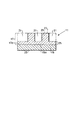
図1は、現像処理において取り除かれる二点鎖線で示された部分を有する感光性要素11を示す。感光性要素11は、可撓性基材15を有する。可撓性基材15上には、実質的に均一な組成物層17が施されており、組成物層17は、それ自体幾つかの層から構成されている。照射硬化性エラストマ系ポリマーにより形成された組成物層17は、接着により、または、化学的に可撓性基材15に接合されている。可撓性基材は、照射硬化可能なポリマーと結合して共に感光性要素11を形成する。可撓性基材15は、外側表面23と、内側表面15aとを有し、内側表面15aは、同様に外側表面27を有する組成物層17の内側表面17aに接合される。
【0027】
熱現像のための感光性要素を作製するために、感光性要素は、内側表面17aに近接する組成物層17の一部を架橋させると共に硬化させてフロア層25を形成すべく、可撓性基材15の外側表面23から化学線に晒される。フロア25の厚さは、特定の印刷用途に要求される基材厚さおよびレリーフ深さに依存し、露出条件および熱処理条件を変化させることによって設定される。可撓性基材が化学線を通さない材料である場合、この工程は省略されるであろう。次に、感光性要素は、感光性要素の所望の部分を硬化させるために、反対側の外側表面27から画像に応じて化学線に晒される。画像に応じた露出の後、照射硬化可能層17の露出領域における硬化部と、照射硬化可能な組成物層17の非露出部分における非硬化部とから感光性要素16が形成される。非硬化部は、およそ0.18〜6.22mmの間の厚さを有する。
【0028】
従来から、感光性要素の反対側の外側表面27の画像に応じた露出に先立って、フロア層25を定着させるための可撓性基材23を通した感光性要素の露出(いわゆる、バックフラッシュ露出)が行われている。ただし、一般に好ましくは、2回の露出の順番を逆にすることも可能であり、画像に応じた露出は、米国特許第5,552,263号においてSchoberらによって開示されているように、バックフラッシュ露出に先立って行われてもよい。
【0029】
画像に応じた露出は、画像担持マスクを通して感光性要素を露出することにより実行され得る。印刷されるべき対象物を含む線画トランスペアランシーまたは線画ネガティブである画像担持マスクは、ハロゲン化銀フィルムまたはこの分野において知られている他の手段によりつくり出されるであろう。マスクは、一時的カバーシートの剥ぎ取りの後、刷版の頂部に配置される。画像に応じた露出は、マスクと刷版の頂部との適正な接触を提供すると共に雰囲気中の酸素を除去する真空フレーム内で行われ得る。そして、刷版は化学線に晒される。露出時に、ネガ(すなわち、マスク)の透明領域は、化学線を通さない領域が架橋されないままでいる間、付加的な光重合または架橋が生じることを可能にする。露出は、露出領域を支持体または後方の露出された層(フロア)へと架橋させるように十分な時間行われる。画像に応じた露出の時間は、典型的には、バックフラッシュ時間よりも長く、数分から10分の範囲にある。米国特許第5、262,275号、米国特許第5,719,009号、米国特許第5,607、814号、van Zoerenの米国特許第5,506,806号、米国特許第5,766,819号、米国特許第5,840,463号および欧州出願公開第0 741 330 A1号に開示されているようなDTP画像形成のためには、赤外線感受層の存在が要求される。照射線を通さず、赤外線を感受する層の画像担持マスクは、赤外線レーザ露出装置を用いて現場にて感光性要素の外側表面に形成される。そのような現場マスクを通した画像に応じた露出は、真空フレームを用いることなく行われ得るものであり、刷版作製処理を単純化する。露出方法は、(1a)マスクを形成するために上述のように感光性要素の赤外線感受層を画像に応じて消散させること、または、(1b)集合体の支持体から、赤外線感受層を感光性要素の外側表面に画像に応じて転写させること、および、(2)マスクを通して感光性要素を化学線に晒すこと、を含む。画像に応じたレーザ露出は、750から20,000nmの範囲で、好ましくは、780〜2,000nmの範囲で発振する様々な形式の赤外線レーザを用いて実行可能である。ダイオードレーザが用いられてもよいが、1060nmで発振するYAGレーザを用いるのが好ましい。
【0030】
化学線源は、紫外域、可視および赤外域を包含する。個別の化学線源の適性は、開始剤と、感光性要素からフレキソ印刷版を作製するのに用いられる少なくとも1個のモノマーとの感光性により調節される。最も一般的なフレキソ印刷版の好適な感光性は、室内光下で十分に安定であるスペクトルの紫外および遠可視領域にある。
【0031】
化学線に晒される組成物層17の部分29は、架橋すると共に硬化する。硬化した照射部分は、高められた融点を有し、通常の条件下でフレキソ印刷インクに不溶である。「通常」の条件には、およそ12〜31℃の間のフレキソ版温度が含まれる。照射されない(露出されない)組成物層の部分は硬化せず、硬化した照射部分よりも低い融点を有する。そして、画像に応じて露出された感光性要素16は、レリーフパターンを形成するために熱現像に備えられる。
【0032】
吸収材は、非照射部分または照射硬化可能な組成物の硬化していない部分の融点を超える融点を有すると共に、同一の動作温度において良好な耐引き裂き性を有するように選択される。好ましくは、選択された材料は、加熱の間に感光性要素を処理するのに要求される温度に耐性を有する。感光性要素の組成物層は、吸収材と接触する間、40〜200℃(華氏104〜392度)の間の温度に加熱される。吸収材は、加熱された感光性要素の照射硬化可能層の表面27と接触すると共に、組成物層17の非照射部分からエラストマ系ポリマーの液化した部分31を吸収し、レリーフパターンまたはレリーフ表面を形成すべく図示されるように部分31が取り除かれたフレキソ印刷版を形成する。非硬化領域における組成物の大部分が可撓性基材15から取り除かれ、吸収材に吸収されると好ましい。液化して硬化していないエラストマを取り除くためには、感光性要素16を新しい吸収材のシートと数回にわたって接触させる必要がある。「溶融」という用語は、吸収材による吸収を可能にするように軟化させると共に粘性を低下させる高められた温度に供された組成物層の非照射部分の挙動を説明するために用いられる。組成物層の溶融可能な部分の材料は、通常、吸収材における吸収のためのある閾値以上の何れかの温度で加熱された組成物層を吸収すべく処理が行われるように、固液間で急激な転移を有さない粘弾性材料である。本発明の目的のために、組成物を「溶融」させるべく、広い温度範囲が用いられるであろう。吸収は、処理の連続動作の間、低温で遅く、高温で早く進むであろう。説明の全体において、感光性要素11は、まだ照射(露出)されていない要素の状態を意味し、感光性要素16、感光性要素シート16、可撓性シート16またはシート16は、照射されてはいるが、まだ非照射(非硬化)部分を取り除くよう十分に現像されていない要素の状態を意味し、感光性要素16a、可撓性シート16a、シート16aまたは、刷版16aは、レリーフパターンを完全に形成すべく非照射(非硬化)部分を除去することにより十分に現像されており、一実施形態において、フレキソ印刷版として用いるのに適している要素の状態を意味する。
【0033】
図2は、本発明の装置の第1実施形態を刷版処理機10として示す。刷版処理機10は、予め形成されると共に予め画像に応じて化学線現像され、処理機10に合った大きさのシート形状を呈する感光性要素16を受け入れる。装置は、支持フレーム12(図6に模式的に示される)、および、支持フレーム12に装着された供給トレイ14を含み、供給トレイ14は、可撓性を有する感光性要素シート16をロードすべく受け入れるのに適したサイズおよび形状を有している。可撓性シート16aは、処理後に、レリーフパターンを有するように形成される。可撓性シート16aは、トレイ14の下方のコンベヤ144によって受け取られる。
【0034】
本発明の刷版処理機10は、図示された実施形態において装置の第1側面19から見て反時計回りに回転するドラム18を含んでいる。ドラム18は、他の機械要素にシート16を支持および搬送する搬送手段として機能する。ドラム18は、ドラムの外面22に横方向に取り付けられた、可撓性シート16の先端をドラムの外面22に固定するための面一に取り付けられたクランプ20を有する。一実施形態では、クランプ20は、細長であり、ドラムの回転方向と反対方向に接線方向に延びる複数の歯26を有する。動作の際、クランプ20は、図3に示されるアクチュエータ手段28によって、外方かつドラム18の外面22から離れるように速やかに起こされる。空気圧シリンダは、垂直方向からおよそ30°の角度で放射状に取り付けられている。空気圧シリンダ30は、それぞれ、ドラム18の(紙面における)回転軸36から離れるように径方向の力を作用させる止め部34を備えた端部32(図5に示される)を有する。アクチュエータ手段28の動作は、図4に示されるようにクランプ20の特徴をまず検討することによって一層明瞭に理解されよう。
【0035】
クランプ20は、実質的に細長い。好ましい実施形態において、クランプ20は、シート16の全幅にわたって延在する。クランプ20の下面には、複数の支持脚38が固定して取り付けられており、支持脚38は、ドラム壁部を通過してドラムの内部に延出する。一実施形態において、支持脚38は、円柱状を呈しており、一実施形態では、矩形バーストックから形成されている横ロッド40に固定して接続されている。
【0036】
横ロッド40の各端部には、実質的にロッド40の中心を貫通する軸44に沿って回転可能に取り付けられたカム従動部42がある。好ましい実施形態において、カム従動部42は、実質的に円柱状を呈する。好ましい実施形態では、カム従動部42なしのロッド40の長さがドラム18の幅よりも僅かに短く、カム従動部42はドラムの側面から外方に延出する。
【0037】
図5に示されるように、空気圧シリンダ30の第1端部32は、制御装置(図示せず)からの信号に応じて矢印48で示されるように逆行する。制御装置(図示せず)は、制御パネル50(図2に示される)からプログラム可能であると共に操作可能である。一実施形態において、制御パネルは、例えば、オン/オフスイッチ、要求されるシートごとのサイクル数を選択するための選択スイッチ、クランプ20を操作するための開閉スイッチ、装置のサイクルを決定するための指示ランプ、および、動作温度を指示するLED読み出し部といった多数の装備を含んでいる。制御装置は、なされるべき動作パラメータの変化を容易に可能にするプログラマブルコントローラであると好ましい。
【0038】
各第1端部32は、カム従動部42の中心シリンダ軸44と実質的に平行な方向に延びる止め部34を有する。止め部34は、カム従動部42と係合し、空気圧シリンダ30が横ロッド40およびクランプ20をドラム18の中心回転軸36(図3に示される)から離れるように持ち上げることを可能にする。クランプ20は、ドラムが休止状態にある際に手動スイッチによって開かれる。また、第1実施形態の装置は、図3に示されるように一対の第2のアクチュエータ54を有し、第2のアクチュエータ54も空気圧シリンダ56であって、フレーム12に強固に取り付けられている。空気圧シリンダ56は、それぞれ、ドラム18が動作する際に異なる回転位置で同一のカム従動部42を受ける止め部60(図5に示される)をもった第1端部58を有する。止め部60は、ドラムの回転中にカム従動部42と係合するので、止め部60のサイズおよび形状は、湾曲されていると共に止め部34よりも大きくされており、止め部34は、ドラムが静止している際に、同一のカム従動部42と係合する。図4を再度参照するに、支持脚38が、クランプ20と横ロッド40との間でクランプ20とロッド40とに固定して取り付けられている。各支持脚38の周りには、引張バネ62が延在しており、引張バネ62は、カム従動部42に全く力が加えられていない際に、クランプ20をドラムの外面22と実質的に面一に保持する。
【0039】
クランプ20は、ドラム18のクランプ受容面66とクランプ20の下面64とによって画成される開口に可撓性シート16の先端24を挿入するに足りるクリアランスを提供するのに十分な高さだけリフトしなければならない。シートを所定位置に保持するために、シート16は、クランプ20の歯26のおよそ1.27cm下方に位置決めされさえすればよい。クランプ20の下面64は、シート16をしっかりと把持すると共にシート16をドラム18の所定位置に保持する下向き突出端部68を有する。
【0040】
制御パネル50(図2に示される)が稼動している際、ドラム18は、「開始」位置にあるべきである。そうではない場合、制御装置は、ドラム駆動モータ73(図6に示される)を作動させて、クランプ20が供給プレート70の前端の僅かに上に位置する「開始」位置にドラム18を前進させる。カム作動マイクロスイッチ71(図6に示される)は、ドラム18が「開始」位置に達すると、ドラムを停止させるために信号を制御装置に送る。
【0041】
供給プレート70は、クランプ20に向けてシート16の先端24を付勢するように僅かに傾斜させられている。好ましい実施形態では、クランプ20を上方に持ち上げ、クランプ20を「開」位置に保持するクランプアクチュエータ28(図3に示される)を作動させるべく、手動スイッチ(図示せず)が通電される。第2の手動スイッチ(図示せず)は、クランプを閉じるために通電される。第3の「開始」スイッチ(図示せず)は、制御シーケンスを始動させる。「開始」スイッチが入れられると、駆動モータ73(図6に示される)は、ドラム18を回転させ始める。ドラム18は、ドラム表面で計測されると好ましくは1分間におよそ76.2cm(リニアセンチメートル)で回転する。
【0042】
一実施形態のドラム18は、およそ55のショアA硬さを有するシリコンラバーの組成物層75によってコートされている。最も好ましいラバーコーティングは、厚さ3/16インチ(およそ4.76mm)のシリコンラバーであり、アルミナ粉体が混入されている。この形式のラバーコーティングは、ミネソタ州ニューホープのRobinson Rubber Product Company, Inc.により市販されている。アルミナ粉体は、ドラムの熱伝導特性を10〜20%の間で改善するものと考えられる。コーティング層75の硬度は、本発明には不可欠ではないが、重要である。本発明のドラムを覆うには、およそ30〜60のショア硬さを有する柔軟なコーティングが適切である。ラバーによって提供される弾性表面は、高温ローラ78(図6)によって及ぼされる圧力のもとで表面が偏向する結果、より長いニップゾーンをもたらすことができる。また、ラバーの弾性は、ドラムと高温ローラとの間の幾つかの軽微な調整不良を吸収する。他の実施形態において、ドラムは、ドラムへのシートの粘着を促進させる薄い粘着性コーティングで覆われた滑らかな金属表面を有する。そのようなコーティングは、Dow CorningのDOW 236である。この薄いコーティングは、感光性要素とドラムとの間の改善された熱伝導性を提供する。この場合、ドラムと高温ローラとの間の軽微な調整不良を吸収するための他の手段が備えられるべきである。
【0043】
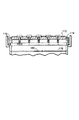
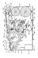
図6は、本発明の第1実施形態による側部断面図を示す。ドラム18は、静止する支持フレーム12に回転するように取り付けられ、矢印72で示されるように反時計方向に回転する。感光性要素シート16(図2に示される)は、供給トレイ14の表面13に配置され、矢印74で示される方向に付勢される。可撓性シート16の先端は、クランプ20に挿入される。シート16は、処理中に、ドラムの表面22と実質的に接触したままとなる。図示された実施形態において、ドラム18上の感光性要素16の組成物層の外側表面27に向けられた焦点輻射ヒータであるヒータ300からなる第1加熱手段がドラム18に近接して配置されている。ヒータ300は、組成物層の非照射部を溶融させて層の一部を液化させるのに十分な温度T2以上の温度T1まで外側表面27の温度を上昇させる。ヒータ300は、組成物層17によって覆われた可撓性基材15を直接加熱しない形式のヒータである。ヒータは、可撓性基材15の外側表面側23から、または、双方の表面27および23からというよりは、むしろ、組成物層17の外側表面側27から熱を加える。これにより、シート16の熱処理の間、可撓性基材15の外側表面23は、温度T1を少なくとも華氏で20度(およそ11.1℃)だけ下回る温度T3に維持される。図示された実施形態において、ヒータ300は、フレーム12に接続された支持体308のようなエンドサポートに取り付けられた電球302,304および306のような複数の管状赤外線加熱バルブを備えており、エンドサポートは、電球との電気的接続を提供する。ドラム18上の感光性要素シート16に赤外線を合焦させると共に向けるリフレクタ310が、ドラムと対向する電球群の側部に近接している。この実施形態では、ヒータ(電球群およびリフレクタ)の中心を通る線が、ドラムを通る径方向線上にあるであろう。リフレクタを備えたエンドサポートに取り付けられている複数の赤外線加熱電球を備えたヒータは、ペンシルバニア州15089ウェストニュートンのTherm Coil/Aitken ProductsのモデルEXT−4502である。
【0044】
本発明の刷版処理機10は、不織材の連続ウェブ76を供給するための搬送手段を含み、連続ウェブ76は、好ましくは、高温ローラ78と接触する。高温ローラ78は、ヒータ300に近接して位置決めされ、ローラ78は、組成物層の非照射部を溶融させて層の一部を液化させるのに十分な溶融温度T2以上の温度T4に、組成物層の外側表面27の温度を維持するか、あるいは、それ以上に上昇させる。高温ローラ78は、組成物層17の外側表面27から熱を加え、可撓性基材15の外側表面23が温度T4を少なくとも華氏で20度(およそ11.1℃)だけ下回る温度T3に維持されることを可能にする。温度T1に加熱すること、および、温度T4に加熱することの双方は、可撓性基材15を歪ませるであろう温度T3を下回るように可撓性基材15を維持するために個別かつ漸増的でなければならない。現像温度T3での0.02〜0.10%を上回る基材の収縮歪みは、最終的使用において問題を生じさせるのに十分であると考えられる。この歪みは、基材の収縮特性と、処理において上昇させられなければならない組成物層の温度との間に不整合が存在する場合、生じてしまうであろう。組成物層の現像温度で高い収縮性を有する基材は、加熱処理の間、組成物層の現像温度よりも十分に低い温度に保たれなければならない。本発明の加熱手段は、組成物層と基材との間の温度の相違が基材の歪みを制御する役割を果たす機能を提供する。基材が必要以上の歪み無しで組成物層の温度に近い温度に耐性を有し得る場合、本発明の加熱手段によって設定される温度の相違は、大きいものである必要はないかもしれない。ただし、一般には、基材の温度を組成物層の温度よりも低く保つことは、一般に有益であると考えられる。
【0045】
感光性要素を構成する材料の熱慣性によっては、非定常状態温度T1およびT4とは異なる時間に、非定常状態温度T3に到達するかもしれない。加熱されたウェブは、感光性要素シート16に熱を伝え、組成物層の一部を溶融させると共に、液化されたポリマーの少なくとも一部を吸収する。ヒータ300と高温ローラ78との組み合わせは、硬化していない組成物層の実質的部分が吸収層によって吸収され、感光性要素16から取り除かれる厚さになるように、組成物層17を加熱する。本発明の第1実施形態では、処理後に不織材76を巻き取るために巻取ロール80が備えられている。一実施形態において、巻取ロール80は、可変速度モータ82によって独立にベルト駆動される。
【0046】
一実施形態では、ドラム18に、感光性要素16を周囲環境の影響を受けない安定な開始温度に保つために設けられたヒータが装備されている。それは、装置が作動させられる箇所で予想される最も高い周囲温度を僅かに超える温度を保つように設定されるであろう。図示されたヒータは、ミズーリ州セントルイスのWatlow Electic Companyから市販されている電気加熱ブランケット21である。一実施形態において、加熱ブランケットは、0.1143cmの厚さ、45.72cmの幅、および、60.96cmの長さを有する巻線ブランケットである。加熱ブランケット21は、2000Wの最大出力を有し、220Vの電力供給を用いる。ヒータの最大出力がおよそ華氏75〜90度(およそ23.9〜32.2℃)のドラムの表面上の選択されたまず一定の膜温度を維持するのに十分なものである限り、ドラムを加熱する手段はどのようなものであってもよい。通常の作動環境が一定の温度に正確に制御される場合、ヒータ21は、電源が切られてもよく、あるいは、装置から省略されてもよい。ヒータ21は、感光性要素16の熱処理の間、温度T1およびT4を少なくとも華氏で20度(およそ11.1℃)だけ下回る温度T3に維持される可撓性基材の外側表面23の温度を保つように常に作動させられるであろう。
【0047】
特定の形式の吸収材は、本発明に不可欠なものではないが、最も好ましい不織材は、フロリダ州ペンサコラのCorex Advanced Fabicsによって製造された不織材であるナイロンランダムウェブのCerex(商標)である。ウェブ材76の選択は、処理される可撓性シート16の溶融可能部分の厚さ、溶融可能部分の溶融温度、可撓性シート16および不織材76の双方の熱伝導特性、および、シート16から吸収材を分離させる間における不織吸収材の強度に大部分を依存する。
【0048】
図6に示されるように、第1実施形態のドラム18は、およそ25.88cmの外径およびドラムの両端間でおよそ48.26cmの幅を有する。一実施形態において、ドラム18は、シートの移動方向に計測して、およそ71.12cmの長さの感光性要素シート16を処理するのに十分な大きさとなっている。また、48.26cmのドラム幅により処理され得るシート16の最大幅は、およそ35.56cmである。処理される複合シート全体の厚さは、およそ0.48〜およそ1.83mmの間の厚さとすることができる。刷版処理機10では、上述された最大寸法よりも小さいものであれば、いかなる可撓性シート16をも処理することができる。
【0049】
制御装置(図示せず)は、制御パネル50(図2に示される)によって提供されると共にプログラム可能である。装置に電源が投入された際、ドラム18は、「開始」位置にある。「開始」位置において、クランプ20の後端は、図4において詳細に示されるように、供給プレート70の近傍にある。供給表面13の上には、ガイドプレート84が回動自在に取り付けられている。可撓性シート16の後縁がガイドプレート84の先端83を通過すると、ガイドプレートは、旋回軸88に沿って(紙面内に)下向きに回動し、シートの長さを算出する制御装置(図示せず)に送られて処理される信号を生成するスイッチ90と係合する。制御装置は、処理サイクルの最後に、この値を用いてヒータ300への電力をいつ切るか、あるいは、いつ減じるか、および、可撓性シート16から吸収ウェブ76をいつ分離させるか、を決定する。
【0050】
クランプ20は、ドラム18が回転している間、可撓性シート16の先端をドラムの外側表面に保持する。回転中にドラム表面22にシート16を保持するために、定常ローラ92が備えられている。定常ローラ92は、一実施形態において、ドラム18の表面22によってシート16が連続的に接触されると共に支持されるように、シート16と外側表面22との間のエアを除くためにドラム18のほぼ最上流位置に位置決めされている。一つの典型的な回転速度は、ドラム表面22において、およそ76.2(リニア)cm/分(30インチ/分)である。先の議論より、輻射ヒータ300と高温ローラ78との作動温度を増加させることによって、装置をより高速で動作させることが可能であろう。また、より低い温度で装置をより低速で動作させることも可能であろう。装置をより高速で動作させることに伴う問題は、組成物が溶融しにくく、ウェブに吸収させる時間を有し、より多くのパスが要求されるであろうということである。より多くのパスは、より高速で動作させることの利点を無にするかもしれず、より多くのパスは、より多くの吸収ウェブ材を消費する。非常に低速で動作させることに伴う問題は、1回のパスにおいてウェブによりあまりに多くの溶融可能な組成物が吸収され、装置のガイドロールをウェブが通過する際に圧搾され、それによって、ロールを汚してしまうということである。最適な動作速度を決定するには、多くの因子のバランスが要求される。
【0051】
図6を再度参照するに、可撓性基材15を少なくとも華氏で20度(およそ11.1℃)だけ低い温度に維持する間に、照射硬化可能な組成物層17の照射されず硬化していない部分の溶融温度を越える温度まで可撓性シート16の外側表面温度を上昇させるためには、ヒータ300は、感光性要素シート16の先端がヒータ300に達する前に通電され、高温ローラ78は、その外側表面が可撓性シート16の先端24と接触するまで矢印94で示される方向に移動される。第1実施形態において、高温ローラ78は、その外側表面と、ローラ78と接触する吸収ウェブ76との間の摩擦によって駆動される。シート上のせん断応力の発生を防止するために、高温ローラ78、ウェブ76およびシート16の線速度が実質的に同一であることが重要である。そのような応力は、好ましくない不均一なレリーフ部の厚さおよび歪んだ画像を生じさせることが知られている。高温ローラは、ドラム18の回転方向72と反対方向に回転する。
【0052】
ウェブ76は、静止する支持フレーム12に回転するように取り付けられた吸収材の供給ロール96から引き出される。吸収材のウェブ76は、高温ローラ78にウェブを実質的に水平に搬送するように位置決めされた第1のアイドラローラ98を通過する。吸収材は、一実施形態において作動されてもよい高温ローラ78と向かい合って接触するようになる。高温ローラの動作温度は、およそ234℃であるが、上限は、一実施形態においておよそ245℃(華氏473度)であるウェブ76の溶融温度によって大部分が決定される。他の温度制限は、基材15の溶融温度である。好ましい一実施形態の基材15は、およそ220℃(華氏428度)の溶融温度を有するポリエステルフィルムである。熱伝導は、定常状態にはないので、245℃までの高温ローラ78の温度は、可撓性フィルム基材15を溶融させない。また、高温ローラ78の温度は、ウェブ76が移動せず、高温ローラ78と接触しているウェブ部分が停止している際に、ウェブが溶融しないよう十分に低くなければならない。高温ロールの温度は、また、可撓性基材15が、現像処理の間、0.02〜0.1%より大きな何れの方向における歪みを生じさせる歪み温度に遭遇しないよう十分に低くなければならない。熱は、ミズーリ州セントルイスのWatlow Electic Companyから市販されているコアヒータにより、高温ローラに与えられる。0.952cmの直径、55.88cmの長さを有すると共に、220Vの給電を利用して1450Wの出力を有するカートリッジヒータは、およそ234℃の膜温度を保つために十分なエネルギを提供するであろう。第1実施形態の高温ローラ78は、電気コアヒータを含むが、本発明は、ウェブを通して組成物層の一部を溶融させるのに十分な膜温度を提供するために蒸気、石油、高温エアおよび様々な他の加熱源の利用を意図している。高温ローラ78は、好ましくは、エラストマコーティング186の層によって覆われるであろう外側表面を有する金属製である。高温ローラ78をコートするには、およそ30〜90の間のショアA硬さ単位という幅広い範囲が適切であると考えられるが、最も好ましいラバーは、およそ50単位のショアA硬さを有する。好ましい実施形態において、ラバーコーティング186は、およそ3/16インチ(4.76mm)の厚さのシリコンラバーである。幾つかの場合、高温ロールは、アルミニウムであって、弾性コーティング無しでアルマイト仕上げされたアルミニウムの外側表面を有する。
【0053】
弾性シート16の長さの測定後、および、カム作動マイクロスイッチ99から先端24が高温ローラ78に最接近した位置にある旨を示す信号を受け取った後、制御装置(図示せず)は、静止するフレーム12に固定して取り付けられた空気圧シリンダ100を作動させる。シリンダ100は伸長し、アイドラローラ98を支持する移動可能フレーム102および高温ローラ78を矢印94で示される方向に移動させる。一実施形態では、シリンダ100が高温ローラ78を「係合」位置まで搬送した後に選択された圧力で高温ローラ78をシート16に対して付勢する引張バネ103がシリンダ100とフレーム102との間に備えられている。
【0054】
図8は、高温ローラ78が係合された状態の装置10を示す。高温ローラ78とドラム18との間のニップ104すなわち間隔は、高温ローラ78がこの好ましい実施形態のための係合位置にある際に、0cmである。その間隔は、処理中におよそ2.11〜4.92kg/cm2の間の実質的に均一な圧力、より好ましくは、およそ3.16kg/cm2の圧力が可撓性シート16の外側表面27のニップ領域に加えられるように設定されることが望ましい。圧力は、吸収ウェブがシート16と強制的に密接するように加えられる。ニップ領域において、およそ0.70〜7.03kg/cm2の間の圧力は、複合感光性要素が歪むことなく、シート表面から吸収ウェブへの吸収を向上させるのに十分であると考えられる。図7は、高温ローラの回転軸に取り付けられた圧力制限装置101を示す。装置101は、ドラムの外側端部上に乗って、シート16に加えられる圧力を制限する。
【0055】
ウェブ76が高温ローラ78を通過すると、その温度は、可撓性シート16のポリマーコーティングの溶融温度を超えなければならない温度まで急速に上昇させられる。図8におけるシリンダ100は、高温ローラ78がドラム18に対して付勢され、ウェブ76とシート16の外側表面27とが密接する状態である伸長位置にある。シート16がニップ104を通過すると、ポリマーコーティングの一部が液化し、ウェブ76に吸収される。一般には、高温ローラ78を横断する単一のパス(1サイクル)は、硬化していない材料のレリーフの十分な深さを除去するには不十分である。このような理由のため、制御装置(図示せず)は、溶融されたポリマーの実質的にすべてがウェブ76に吸収され得るように、ドラムが全体で数回の完全な回転を行うことを可能にすべくプログラムされている。感光性要素、加熱出力、高温ロール温度、および、ドラム速度のある状態として、組成物層の非硬化部分を所望量だけ取り除くために、12〜15サイクルを用いることもできる。
【0056】
好ましい一実施形態は、溶融したポリマーのすべてを取り除くために9パスを要求するが、より好都合な熱伝導特性をもったより高い吸収性を有する吸収材を選択すると共に、除去されるべき層の厚さといった他のパラメータを変化させることにより、9パス以下で所望の吸収を達成し得ることは理解されよう。同様に、他の構成によれば、可撓性シートを、ヒータ300および高温ローラ78に9回以上通過させる必要があるであろう。
【0057】
吸収後、ウェブ76は、好ましい実施形態ではモータ108によってベルト駆動される駆動ローラ106を通過する。一実施形態において、モータ108は、可変速度モータである。モータは、ドラム18および高温ローラ78上のシート16の外側表面の線速度と同期する線速度で装置10を通してウェブ76を引張るサイズのものである。
【0058】
第1の好ましい実施形態において、駆動ローラ106は、研磨性外表面を有する。駆動ローラ106は、好ましくは、サンドペーパーのような研磨材でコートされている。研磨コーティングは、ローラ106とウェブ76との間の摩擦力を向上させ、すべりを防止する。一実施形態において、ウェブ76は、駆動ローラ106の外側表面の少なくとも3分の1に接触し、装置10の全体においてウェブに実質的に均一な張力を与えることを補助するアイドラローラ110に巻き掛けられている。アイドラローラ110に加えて、例えば、駆動ローラ106がウェブを引張る前に、ウェブ供給ロールが急速に展開し過ぎることを防止するブレーキ112が備えられている。
【0059】
第2のアイドラローラ114は、ウェブ76に張力を保つために任意に備えられる。ウェブ76は、ローラ110および114の間から出た後に、他の一対のガイドローラ116および118に向けられ、巻取ローラ80によって回収される。
【0060】
一実施形態において、巻取ローラ80は、可変速度モータ122によってベルト駆動される。このモータの速度は、回収されるウェブの引張りの支障をきたさないように調整されなければならない。モータがウェブの引張りに干渉する場合、この方式により形成されるレリーフパターンを有する最終的に形成された可撓性シート16aが、例えば、一定の高さのレリーフ部を有さず、あるいは、歪んでしまい、フレキソ印刷版として商用的に許容されなくなってしまうかもしれない。
【0061】
他の実施形態によれば、静止するフレーム12に直径センサ124が装着され、直径センサ124は、巻取ロール80に巻き取られる吸収材の外径を測定する。センサ124が回動すると、センサからの出力電圧が変化する。更に他の実施形態では、磁性粉体クラッチ(図示せず)が巻取ロール80を支持する回転軸に取り付けられ、変化するセンサ124からの出力電圧が巻取率を制限するように軸へ加えられるトルクを変化させる。このクラッチ機能は、巻取ロール80の近傍でウェブ76の部分への実質的に均一な張力を維持する。
【0062】
他の実施形態では、供給ロール96にも、センサ124と実質的に同様の仕方で動作する直径センサ126が装備される。変化する電圧が、供給ロール96を支持する軸に加えられるトルクを変化させ、ウェブ76に一定の張力を維持する。供給ロール96の巻解きを制限するためのブレーキを置き換えるための代替的装置の一例は、磁性粉体ブレーキである。アイドラローラ110/駆動ローラ106の配列および磁性粉体ブレーキは、均一な張力が加えられて実質的に一定の速度で移動するウェブ76を搬送する。これに対して、ブレーキ112は、単に、ウェブにおける張力を大まかに維持する。
【0063】
第1実施形態において、ガイドローラ98、高温ローラ78、駆動ローラ106、駆動モータ108およびアイドラローラ98,114は、すべて、空気圧シリンダ100によって作動される移動可能な支持構造体(移動可能フレーム)102に取り付けられている。図8および図9に示される移動可能な支持構造体102は、一対の支持ブラケット132および134を通ってドラム18に向けて水平にスライドする2本の離間されたロッド128および130から吊り下げられている。第1実施形態において、支持ブラケット132および134は、静止するフレーム12に固定されている。動作時に、図8に示される空気圧シリンダ100が作動されると、移動可能な支持構造体102の全体は、離間されたロッド128および130に沿って高温ローラ78がドラム18と接触するまでスライドする。この位置は、高温ローラ78の「走行位置」と称される。
【0064】
第1実施形態の制御手段(図示せず)は、感光性要素シート16の先端24がヒータの端部300aに達する前に、ヒータ300をオン状態にする。また、制御手段は、可撓性シート16の先端24(図6に示される)がニップ104に達すると、速やかに支持構造体102上のアッセンブリを走行位置に移動させる。一実施形態において、高温ローラ78は、ウェブ76の温度をおよそ234℃に上昇させる。この温度では、加熱されたウェブと接触する可撓性シートの上層の非硬化部分が液化する。複合可撓性シート16の熱伝導特性によっては、吸収後、可撓性シート16からウェブ76を直ちに分離させる必要がある。これは、可撓性シート16の表面からウェブ76を、角度135として示されるように、シート16の移動方向からおよそ90°の方向に引き離すことにより達成される。少なくとも45°の角度で吸収材を引き離すことが、液化したポリマーが冷却して再硬化する前に、ウェブからシートを外すために必要であると考えられる。好ましい角度の範囲は、75〜105°の範囲にあり、最も好ましい角度は、およそ90°である。ニップ104における吸収時点の後、可撓性シート16は、僅かに撓んでドラム18から短時間のうちに離れる。水平よりも僅かに下方への角度でウェブ76を引張ることにより、可撓性シート16とウェブ76とは速やかに分離する。可撓性シート16の後端がヒータ300の範囲を通過すると、制御装置は、シート長さおよびヒータの特性に応じてヒータ300への電力を断つか、あるいは、減じるであろう。可撓性シート16の後端がニップ104を通過すると、制御装置(図示せず)は、高温ローラ78をドラムから離すように移動させ、駆動モータ108を停止させ、先端がヒータ300とニップ104とに戻るように、感光性要素シート16を再度進行させる。この「急速進行」機能は、時間を節約するために通常の3〜4倍の速度でドラムを回転させ、装置能力を改善する。この急速な進行は、ドラム上のシートの後端と先端との間にはかなりの間隔が存在するので、シート長さがドラムの外周に対して短い場合にのみ用いられる。
【0065】
ブレーキ112は、ドラム18が新たなサイクルを開始するために前進する間、ウェブ76の移動を停止させる。ブレーキ112は、無駄な使用されていないウェブ材76を除去する。典型的な一実施形態において、装置は、各シート16について9回の吸収工程を行う。9サイクルの終了時に、そして、感光性要素の後端がニップ104を通過すると直ちに、制御装置は、シート16の後端を配置する前に行われた測長を利用するタイミングシーケンスを開始する。シートの後端がヒータ300およびニップ104から離れると直ちに、制御装置は、ヒータへの電力を断つと共に、高温ローラ78をドラムから離れるように移動させ、駆動モータ108を停止させる。ドラムが回転し続けている際、カム作動マイクロスイッチ109は、ドラム18のカムと係合して制御装置によって受け取られる信号を生成する。制御装置は、完全に形成されているフレキソ版16である可撓性シートの先端を開放するクランプアクチュエータ54(図3に示される)を作動させる。
【0066】
また、可撓性版16aの先端は、供給トレイ14の下面に一端が回動自在に取り付けられた空気圧シリンダ138を含む剥ぎ取り装置136によって、ドラムから解放されることを支援される。シリンダの反対側の端部には、好ましい実施形態においてドラム幅の端から端に横方向に延在する剥ぎ取りブレード140が回動自在に取り付けられている。最も好適な剥ぎ取りブレード140は、ドラムの外側表面に向けて延びると共にクランプ20(図2に示される)の歯26と噛合う複数のフィンガーを有する。制御装置(図示せず)は、最後のサイクルの終了時に、剥ぎ取りブレード140をドラム18の外側表面と接触するまで延出させる。形成されたフレキソ版の先端は、ドラムの外側表面からそっと持ち上げられて取り外され、刷版は、矢印142で示される方向に移動される。最も好ましい実施形態では、コンベヤ144が、装置10から形成された刷版16aのそれぞれを取り出す。第1実施形態においてコンベヤ144の一部であるアイドラローラ168は、高温ローラ78と剥ぎ取り装置136との間に位置決めされる。このローラ168とドラム18との係合は、クランプ20が先端を開放した後、刷版16aを駆動する。
【0067】
図9を再度参照するに、吸収ウェブ材76の供給ロール96は、一実施形態ではブレーキ148および150である引張手段に装備された軸146に取り付けられている。ブレーキ148および150は、それぞれ第1端152(図8に示される)において固定して取り付けられた可撓性ストラップから形成される。ストラップは、一実施形態において実質的に滑らかな外側円柱面を有するシーブ154および156の周りに巻き付いている。シーブ154および156は、供給ロールの軸146に固定して取り付けられている。一実施形態によるブレーキ148,150は、可撓性レザーストラップを含む。ストラップは、静止する支持フレーム12に固定して取り付けられた第1端152と、それぞれ静止するフレーム12に固定して取り付けられている引張バネ158および160が備えられた反対の端部とを有する。
【0068】
動作時には、ブレーキ148および150は、ウェブ76が駆動ローラ106によって引張られるとウェブ76に張力を与える。供給ロール96の直径が変化すると、その張力は僅かに変化する。他の実施形態では、供給ロール96の外径を検出するセンサ126が備えられる。センサ126は、回動位置により変化する電圧を有するポテンシオメータである。電圧出力は、軸146に取り付けられて軸146のトルク出力を変化させる磁性粉体ブレーキ(図示せず)に送られる。磁性粉体ブレーキおよびセンサ126は、共に、ウェブ76に実質的に一定の張力を維持する。
【0069】
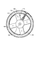
図10は、本発明の好ましい実施形態のドラム18を示している。本発明の重要な形態は、最もスムースに実行可能な回転を達成すると共にバックフラッシュを防止するようにドラムの運動を設計することである。ギヤ162は、ドラム18の第1端164に取り付けられており、ドラム18の外側表面22のごく近傍の地点でピニオン163と噛合っている。第1の実施形態では、モータ73に供給される電流の方向を反転させる電気回路から構成されるブレーキがドラム18の回転を停止させるために備えられている。このブレーキ法は、発電ブレーキとして一般に称されるものである。図11を参照するに、ピニオン163のシャフトの中心軸166は、ギヤ162とピニオン163とが外側表面22近傍の地点で噛合うように、ドラム18の外側表面22に対して密に間隔を置かれている。
【0070】
図10に示される一実施形態におけるアイドラローラ92は、可撓性シートに、例えば、その自重分だけ微小な圧力を作用させる。アイドラローラ92は、可撓性シート16の下方から閉じ込められたエアを強制的に除去し、可撓性シート16とドラム18との間の熱伝導を改善する。第2のアイドラローラ168は、アイドラローラ92からおよそ180°離間されており、クランプ20が先端を開放した後に可撓性シート16を駆動する役割を果たす。アイドラローラ168もまた、装置10から形成された刷版を移動させるコンベヤ144(図8に示される)の一部である。一実施形態において、ローラ168は、ドラム18に対してバネ付勢される。
【0071】
最も好ましい実施形態の制御スキームは、装置10を制御するためにカム作動スイッチおよびタイマを使用するものであるが、図10は、本発明の動作を制御する代替的装置を示している。この装置では、一連のパルスを生成して多数のカウンタに送出するエンコーダ170が備えられている。カウンタは、装置10を制御するために公知の手段を用いる。エンコーダ170の代わりとなるものは、ドラム18に取り付けられたギヤ162のギヤ歯をカウントして、装置10を制御するために必要なパルスを生成するセンサ(図示せず)である。
【0072】
図12は、一実施形態におけるドラム18の設計の他の形態を示している。ドラム18は、ドラムの表面を歪ませると共に許容し得ないフレキソ版を作り出してしまう熱応力を防止するように構成されている。ドラム18は、主壁部172を有する。実質的に円筒状の主壁172の各端部には、ハブ174および176が取り付けられており、ハブ174および176は、両者を通って延びる4本の離間されたタイロッド178によって所定位置に保持されている。各タイロッド178の中央近傍には、ハブ174および176を主壁部172に対して保持する機能を有すると共に、主壁部172が回転軸と実質的に平行な方向に円滑に伸長することを可能にする引張バネ180がある。
【0073】
図13は、一方のハブの構成を示す。各ハブ174,176は、中心スタブシャフト182に取り付けられている。一実施形態において、1つのスタブシャフト182は、中空である。タイロッド178は、それぞれおよそ90°おきに配置されたアーム184に取り付けられている。ドラム18のこの設計は、シャフト182の軸に平行な方向における伸長を提供するだけでなく、全ての方向への伸長を可能にする。また、ハブ174および176には、一実施形態において、互いにおよそ90°をおいて配置されており、ドラム18の主壁部172からキー(図示せず)を受容する4個のスロット188が装備されている。スロット188およびキー(図示せず)は、ドラム18の回転軸に対して主壁部172が同心を保つことを確実にすると共に、ハブ174および176と主壁部172との間の相対的な回転移動を防止する。
【0074】
図14は、感光性要素16の熱現像を行う刷版処理機10の第2実施形態を示している。図14の処理機は、図2に示される処理機10と類似しており、同様の要素には同一の参照符号が付されている。図14の場合、明確化のために装置のカバーが外されている。図14に示される本発明の第2実施形態は、支持フレーム12(図15に概略的に示される)、および、支持フレーム12に取り付けられた供給トレイ14を含み、供給トレイ14は、可撓性を有する感光性要素シート16をロードすべく受け入れるのに適したサイズおよび形状を有している。刷版処理機10aは、図示された実施形態において装置の第1側面19から見て反時計回りに回転するドラム18を含んでいる。ドラム18は、他の装置要素へフィルムのシートを支持および搬送する搬送手段としての役割を果たす。ドラム18は、ドラムの外面22に横方向に取り付けられた、可撓性シート16の先端をドラムの外面22に固定するための面一に取り付けられたクランプ20を有する。一実施形態では、クランプ20は、細長であり、ドラムの回転方向と反対方向に接線方向に延びる複数の歯26を有する。最終シートサイクルの後に処理が完了すると、完全に形成されたレリーフパターンを備えた可撓性シートすなわち刷版16aは、トレイ14の上方に配置されたコンベヤ144aによって受け取られ、コンベヤ144がトレイ14の下方に配置されている図2の第1実施形態10とは細部で異なっている。剥ぎ取りブレード140は、ドラム18の外側表面に向けて延びると共にクランプ20の歯26と噛合う複数のフィンガーを有する。アイドラローラ168は、剥ぎ取りブレード140の近傍に配置されている。このローラ168は、ドラム18と接触すると、シートの最終サイクルの完了時にクランプ20が先端を解放した後にシート16を駆動する。制御装置(図示せず)は、制御パネル50によって提供されると共にプログラムされる。
【0075】
図15は、図6の第1実施形態10に類似する第2実施形態10aを示している。図14の場合のように、第1実施形態と同様の要素には、同一の参照符号が付される。ドラム18は、静止する支持フレーム12に回転するように取り付けられ、矢印72で示される反時計方向に回転する。感光性要素シート16(図14に示される)は、供給トレイ14の表面13に配置され、矢印74で示される方向に付勢される。可撓性シート16の先端は、クランプ20に挿入される。シート16は、処理中に、ドラムの表面22に実質的に接触したままとなる。図示された実施形態において、ドラム18上の感光性要素16の組成物層の外側表面27に向けられた焦点輻射ヒータであるヒータ300からなる第1加熱手段がドラム18に近接して配置されている。ヒータ300は、組成物層の非照射部を溶融させて層の一部を液化させるのに十分な温度T2以上の温度T1まで外側表面27の温度を上昇させる。ヒータは、可撓性基材15の外側表面側23から、または、双方の表面27および23からというよりは、むしろ、組成物層17の外側表面側27から熱を加え、シート16の熱処理の間、可撓性基材15の外側表面23が温度T1を少なくとも華氏で20度(およそ11.1℃)だけ下回る温度T3に維持されることを可能にする。図示された実施形態において、ヒータ300は、支持体308のようなエンドサポートに取り付けられた電球302,304および306のような複数の管状赤外線加熱バルブを備えており、エンドサポートもまた、電球との電気的接続を提供する。ドラム18上の感光性要素シート16の組成物層17の外側表面27に赤外線を合焦させると共に向けるリフレクタ310が、ドラムと対向する電球群の側部に近接している。図16を参照するに、この第2実施形態のヒータは、線311により示され、ヒータバルブの中心およびドラムの中心を通る径方向線309から角度307をなしているその対称線を有している。これにより、ヒータ300からの放射は、ドラム18と高温ローラ78との間でドラムおよび高温ローラの中心を結ぶ径方向線303に沿って横たわっているニップ305に近づけられる。図15の第2実施形態において、角度307はおよそ15°であり、第1実施形態において、角度307(図示せず)は0°となるであろう。
【0076】
刷版処理機10aは、不織材の連続ウェブ76を供給するための搬送手段を含み、搬送手段は、好ましい実施形態において高温ローラ78である。高温ローラ78は、ヒータ300に近接して位置決めされ、ローラ78は、組成物層の非照射部を溶融させて層の一部を液化させるのに十分な溶融温度T2以上の温度T4に、組成物層の外側表面27の温度を維持するか、あるいは、それ以上に上昇させる。温度T1に加熱すること、および、温度T4に加熱することの双方は、可撓性基材15を歪ませるであろう温度T3を下回るように可撓性基材15を維持するために個別かつ漸増的でなければならない。現像温度T3で0.02〜0.10%を上回るの基材の収縮歪みは、最終的使用において問題を生じさせるのに十分であると考えられる。感光性要素を構成する材料の熱慣性によっては、非定常状態温度T1およびT4とは異なる時間に、非定常状態温度T3に到達するかもしれない。第1実施形態とは異なり、第2実施形態では、高温ローラ78は、図17Aに示されるアクチュエータ320および322の付勢のもと、旋回軸316および318の周りで回動するアーム312および314に取り付けられている。アクチュエータ320および322は、ビーム324に取り付けられており、ビーム324は、一端326が2個の弾性ブッシュ328および330によってアーム312に取り付けられ、反対側の端部332において、ビーム324は、2個の弾性ブッシュ334および336によってアーム314に取り付けられている。2体のアクチュエータ320および322は、ビーム324を付勢するために一斉に作動するが、同様の作用を達成するために、ビーム324の中央に、より大きく、より高圧の単一のアクチュエータを用いてもよい。アーム312および314は、ドラム18と高温ローラ78との間の相対運動を提供すべく図8の第1実施形態において移動可能フレーム102が行ったのと同様の機能を果たす。
【0077】
図17Bは、ブッシュがビーム324をアーム312および314に接続している方式を示している。図17Bは、アーム312の穴338を貫通すると共に、ビーム324の端部326に当接する中空円筒ブッシュ330を示している。ショルダーボルト340は、ワッシャ342を貫通すると共に、ブッシュ330の中空パッセージ344を貫通し、ビーム324の端部326のネジ穴346に螺合されている。肩部340aが端部326にきつく当接するように、ボルト340が穴346に十分に螺合されると、ボルト340は、弾性ブッシュ330を軸方向に圧縮し、アーム312の穴338とフィットした状態であるが弾性的に係合するようにブッシュ330を径方向に拡長させる。ビームの各端部においてそのような2個のブッシュを用いることにより、アーム312および314に対するビーム324の回転が防止される。ビームの各端部におけるブッシュは、取り付けられた高温ローラ78をドラム18に対して矢印315で示される方向に付勢し、感光性要素に対して吸収ウェブを押圧するようにアクチュエータがビームに対して作動する際、各アームの少量の個別移動を可能にする。これにより、ドラム上の感光性要素に対する高温ローラの自己調整が可能になると共に、設定が困難であるドラムに対する高温ローラの正確な機械的調整が解消される。
【0078】
高温ローラ78の下方かつその近傍には、フレーム12に回動自在に取り付けられたスイングアーム317のようなスイングアームの各端部に取り付けられているアイドラローラ313がある。各スイングアームは、一端がフレーム12に取り付けられると共に反対側の端部がアーム315に取り付けられているバネ319のようなバネによってドラム18に対して付勢されている。アイドラローラ313は、感光性要素シートが高温ローラから出ると共に吸収ウェブがシート16から剥ぎ取られている際に、ドラムに対して感光性要素シート16を押圧するようにドラム18に向けて連続的に付勢される。シートの後端が高温ローラを離れた後に、それが重力の影響によってドラムから剥がれ落ちないように、シートの後端をドラムに対して押圧すると好ましい。
【0079】
吸収ウェブ76の巻取経路は、図6および図15にそれぞれ示されているように、第1実施形態10と第2実施形態10aとの間で僅かに異なる。図15において、ウェブ76は、供給ロール96から巻き出され、曲がりくねった経路のロール348および350の間を通過する。供給ロール96は、ウェブ76に軽い巻き出し張力を保つ軽摩擦ブレーキに接続されている。ロール350は、電磁ブレーキに接続され、ロール348は、バネ付勢されたニップロールであり、このロールの組み合わせは、供給ロールブレーキとは独立にウェブに作動張力を加える役割を果たす。ウェブ76は、高温ローラ78に案内されると共に駆動ローラ106aおよび他のバネ付勢されたニップロールであるアイドラローラ110aに案内される。ローラ106aおよび110aの組み合わせは、第1実施形態のローラ106および110(図8A参照)と同様に、ドラム16上のシート16の表面速度と合致する制御された表面速度でウェブを駆動する役割を果たす。そして、ウェブ76は、巻取ロール80に巻き取られる。駆動ローラ106aは、モータ108aによって駆動され、モータ108aは、磁性粉体クラッチを介してウェブに軽い巻取張力を保つように巻取ロール80をも駆動する。
【0080】
第1実施形態と比較して他の重要な第2実施形態の相違点は、ウェブの一側および他側に向けられ、ドラム18から離れるように搬送されるウェブ76に吸収される液化した組成物層を硬化させる紫外線ランプ352および354が追加されている点にある。この硬化補助は、ウェブ76用の駆動ローラおよびアイドラローラ上の液化した組成物の堆積を最小化する。そのようなUVランプとしては、コネチカット州06430フェアフィールドのVoltarc Technologies,Inc.から、モデルNo.FR30T8/BL9/BP/180を得ることができる。
【0081】
第2実施形態において、冷却手段355が備えられており、冷却手段355は、ブロア356と、ドラムの表面22の近接してドラムの周りに沿った方向に延びるように配された光学シュラウド358とを備える。冷却手段は、感光性要素シートを冷却するための吸収材ウェブ76から感光性要素が分離される箇所に位置決めされている。ブロアは、ドラム18上のシート16の表面にエアの流れを向け、シュラウド358(任意である)は、ドラムの一部の周囲にエアの流れをドラムの回転方向と反対の方向に向ける。そのようなブロアとしては、コネチカット州06430ファーミントンのEBM/Pabst Companyから、モデルQK08B−2EM.70.CHを得ることができる。冷却手段の他の一実施形態は、直接接触により可撓性基材15を冷却するようにドラム支持表面22の下方に冷却流体を循環させることである。これは、冷却手段355に代わる実施形態として、または、それを補充するものとして利用され得る。そのような冷却手段が採用されれば、図6の第1実施形態におけるヒータ21について言及した、上述の加熱によるドラム温度の安定化は採用されず、ドラム温度は、代わりに冷却によって安定化されるであろう。
【0082】
冷却手段の他の実施形態は、第1または第2実施形態のドラム構造体18の内部を通してエアのような冷却ガスを強制的に循環させることからなる。図19は、ドラム18の壁部172の内側表面424に近接して環状プレナム420およびパッセージ422が備えられているそのような配置の一例を示している。パッセージ422は、シートクランプ20(図6および図15)が配置されるであろう箇所を除いて、内側表面424の外周面の実質的部分の周りに延在している。パッセージは、軸端426および428で開放されている。プレナム420は、パッセージ424の実質的部分の周りに延在しており、支柱420および432のような複数の支柱と、ハブ174および176とによって内側表面424に取り付けられている。冷却エアは、複数の電動ファン434によってプレナム420に強制的に導入される。エアは、プレナムの複数のオリフィス436を通って、矢印438のような矢印によって概ね図示されるように、環状パッセージ420に流れ込む。オリフィス436からのエアが内側表面424に直接衝突することにより、知られている「エア衝突ジェット冷却」によって表面424からの熱伝導が増加する。パッセージ420から、矢印440のような矢印によって概ね図示されるように、エアは、端部においてドラムを出る。フレッシュエアは、矢印444のような矢印によって概ね図示されるように、ドラム18の内部442を介してファンに供給される。ドラム18の内側表面424に近接したエアの循環は、主壁部172および外側表面22から熱を取り除く。外側表面22と接触する可撓性基材15と組成物層17とを備える感光性要素のシート16は、ドラム18の主壁部172の外側表面22に取り付けられる。要素16は、可撓性基材が組成物層よりも低い温度まで冷却された状態で、主壁部172および外側表面22から熱を取り除くことによって冷却される。
【0083】
ドラムおよび高温ロールの加熱要素をそれぞれ制御すべくロール温度をモニタするために、温度センサがドラムおよび高温ロールに近接して取り付けられる。また、それらは、いつ装置をウォームアップし、開始準備するかを決定するために、装置制御装置によってモニタされる。図15を参照するに、冷却手段の直後の位置にドラム18の表面22の横方向端部表面または端部に近接して、センサ357が配置されている。このセンサは、赤外線センサであり、バージニア州24540ダンビルのElectronic Development Lab,Inc.から、モデルCI−1−B、Type J,0−500Cとして得ることができる。また、図17Aを参照するに、ウェブ76によって巻き付かれることがなく、ドラム18と対向する高温ロール78の背後に高温ロールの表面の横方向端部に近接して、センサ359が配置されている。このセンサは、アーム312に取り付けることにより支持されている。このセンサは、ドラムセンサ357と同様のものである。このセンサは、シート16の処理の開始時またはシート16についての何れか1回の処理サイクルの間に制御装置によって変化される高温ロールの実際の温度をモニタするために用いられる。
【0084】
メインテナンスのために、吸収ウェブロール96および80と、ロール348,350,78,106aおよび110aの案内システムと、要素320,322,324,312,314を含む高温ロール駆動システムとは、すべて、点検が必要とされた際に、主装置フレーム12から転がし出すことができるカート360に搭載されている。カートは、フレーム12のベースプレート366上に載っているか、あるいは、ベースプレートが備えられていない場合にフレーム12が休止しているのと同一の支持フロア上に載っている車輪362,363および364のような車輪を有する。装置フレーム12は、コンベヤ114aの下部と共にプレナムを形成し、蒸気がシート16の組成物層を加熱することを防止する吸引ファンユニット368によって換気される。ユニット368からの排気は、コンジット370から排出される。ユニット368の入口は、複数のインレット369およびユニットの端部の入口371のようにユニットの低部に沿っている。
【0085】
図面、特に図15を参照しながら、以下、第2実施形態の好ましい一動作の簡潔な説明がなされる。この点に関し、図14および図15の刷版処理機10aは、フレーム12内に配置されると共に制御コンソール50(図14)に接続されたプログラマブル論理制御装置(PLC)372を有していることに注目されたい。制御装置372は、外部データ通信ネットワークと接続するためのモデム374を含んでいる。モデム374は、制御装置372から作業データを遠隔収集すると共に、制御装置372にコマンドを遠隔的に与えることを可能にする。刷版処理機10aは、供給トレイに近接しているドラムの上部近傍に位置決めされているクランプ20に対してドラムが静止しているホームポジションにある。オペレータは、供給トレイ14上にシート16を載置する。そして、オペレータは、コンソール50のキーパッドを用いてシートについての情報を入力する。そのような情報は、シートの化学式(使用される適切な温度および圧力を決定するために制御装置372によって用いられる)、シートの全厚さ(シートの予め定められた表面速度に基づいてドラムの回転数を決定するために用いられる)、シートの幅(高温ロールのための圧力を設定するために用いられる)、および、完成されたシート(すなわち刷版)についての所望のレリーフ深さ(要求されるサイクル数または高温ロール下のシートのパス数を決定するために用いられる)である。
【0086】
そして、オペレータは、クランプ20を開き、シート16の先端をクランプ20に嵌め、シート16の先端上にクランプ20を閉じるべくコンソール50のボタンを押圧する。制御装置は、処理機10aのウォームアップを開始させ、ウォームアップすると、「準備完了」ランプによってオペレータにその旨を知らせる。ドラム18を予熱するために、ドラムヒータ21または赤外線ヒータ300が用いられるであろう。高温ロール78を加熱するために、高温ローラ用のカートリッジヒータ(図示せず)が用いられる。そして、オペレータは、コンソールの「開始」ボタンを押圧する。ドラムは、回転を開始して、それと共にシートを搬送し、アイドラローラ168(第1実施形態において定常ローラ92としても機能する)は、シートをドラムの表面22に押圧するようにドラム18に向けてバネ付勢される。可撓性シートの後端が供給トレイの先端を通過すると、スイッチ90(図4を参照して説明された第1実施形態と同様に)は、制御装置372に送られて、シートの「長さ」を算出すると共にシートの後端の位置を求めるために制御装置372によって処理される信号を生成する。シートがヒータに達する前に、電球を予熱するためにヒータ300は最大出力に通電される。ドラム上のエンコーダ(または、ギヤ歯センサ)は、シート16の先端を保持したクランプがいつヒータの先端に達するか、を制御装置に伝え、シートの組成物層を溶融させるために所望の温度T1を設定するように動力が作業セッティングに切り換えられる。高温ロールがドラムと接触することになる位置にシートの先端が達すると、制御装置は、シート16に対して高温ロールを回動させるために、高温ロールアクチュエータに信号を送ると共に、ドラム上のシートの表面速度に合致する速度でウェブ76を駆動するために、シート厚さに関連する計算された表面速度に基づいて、駆動ローラ106aに信号を送る。ドラムおよび高温ロールの速度および位置の正確な制御を確保するために、これらの要素のそれぞれを駆動するモータは、交流誘導モータとされている。
【0087】
シート16の後端が高温ロールとドラムとの接触点を通過すると、制御装置は、ヒータ300への電力を(シート長さおよびヒータの作動特性に基づいて)断つか、あるいは、減じ、高温ロールを退避させるためにアクチュエータ320および322に信号を送ると共に、ウェブの駆動を停止させるために駆動ローラ106aに信号を送る。同時に、制御装置はまた、他のサイクルを開始するために、シート16の先端をホームポジションまで戻すように増速させるべく、ドラムに信号を送るであろう。シートが短い全長を有している場合、このドラムの増速により、処理時間が節減され、シートが長い全長を有している場合には、後端が高温ロールとドラムとの接触点を通過する時間までに、先端が既にホームポジションに達しているか、あるいは、超えているであろうことから、この増速は省略されるであろう。長いシートについては、最初のサイクルについて供された最大出力加熱を省略するために、オンされたままとされるであろう。シート長さに拘わらず、選択されたシートに要求される残りのサイクルの間、ヒータを作業出力で連続的にオンしたままにしておくのが好ましいであろう。一実施形態において、短い全長をもったシートの場合については、第2サイクルが最初のサイクルと同様となるであろう。冷却ブロア356および換気ブロア368は、開始ボタンが作動されと、電源投入され、要求される全サイクルの間、オン状態とされるであろう。
【0088】
感光性要素の各サイクルについて、ドラム速度、ヒータ出力、高温ロール出力、高温ロール圧力、および、冷却エア体積(ブロア速度)のような装置作業パラメータを制御装置が変化させることを可能にすることによって、刷版処理機の動作が変化され得ることが意図されている。ある場合には、冷却媒体温度もまた変化され得る。パラメータは、一のサイクルから次のサイクルへと変化されるか、あるいは、数サイクルについて一定に保持され、変化させられてもよく、あるいは、最初のサイクルについてあるセッティングを、中間のサイクルについて他のセッティングを、最後のサイクルのついて他のセッティングを有していてもよい。セッティングは、同一形式の幾つかについて集められた実験的データに基づいて予め定めることが可能であり、シートのサイズまたはセッティングは、ドラムおよび高温ロールのモニタされた温度の変化に基づいてリアルタイムで変更可能である。
【0089】
温度T1を少なくとも華氏で20度(およそ11.1℃)だけ下回る温度T3に可撓性基材を維持しながら、組成物を溶融させるのに十分な温度T1まで組成物層を直接加熱するヒータ300を用いると共に、温度T4を少なくとも華氏で20度(およそ11.1℃)だけ下回る温度T3に可撓性基材を維持しながら、組成物を溶融させるのに十分な温度T4まで高温ロールによって組成物層を加熱することは、従来技術のシステムを超えた著しい改善といえる。
【0090】
(試験結果)
温度の検討
図18Aは、システムの温度挙動を考察した処理の温度履歴を示している。用いられた刷版処理機は、第1実施形態のように位置決めされた赤外線ヒータを備えると共に、ブロアシュラウドを備えていない第2実施形態に類似したものであった。厚いラバーコーティング形態を備えたドラムが使用された。図18Aおよび図18Bを参照する第1の状況において、冷却手段は用いられてはおらず、換気ユニットは、連続的に作動されている。温度を記録するために、第1の熱電対がシート16の可撓性基材の外側表面23に位置させられ、第2の熱電対が同一シートの組成物層の外側表面27に位置させられた。双方の熱電対は、幅30インチ(762mm)、全長40インチ(1016mm)のシートの完全照射(硬化)シート領域の中央に配置された。シートは、厚さ0.067インチ(1.70mm)であり、厚さ5ミル(0.13mm)の可撓性基材を備えていた。組成物層は、溶融可能ではなく、この試験中にレリーフは形成されなかった。そして、シートは、12サイクルだけ処理され、所望量の組成物層を取り除くために12サイクルの動作を要求するであろう感光性要素をシミュレートすべく2体の熱電対について温度が計測された。処理機の動作において、ヒータ300は、開始時に5400Wヒータについて30%出力の設定値で通電され、電球表面でおよそ華氏790度(420℃)の温度がもたらされた。20%出力では、電球温度は、およそ華氏660度(350℃)であった。アクチュエータに60psi(413700Pa)の圧力が用いられ、シートには、幅あたり、およそ59.4ポンド/リニアインチ(8.21N)の圧力が加えられた。高温ロール(現像ロール)の温度は、華氏170〜210℃(76.7〜98.9℃)の吸収のための組成物表面温度T4(およそ華氏160度〔71.1℃〕の推定される溶融温度T2よりも高い)を生じさせる華氏235度(112.8℃)に設定された。ドラム上のシートの表面速度は、30インチ/分(76.2cm/分)に設定された。第2の熱電対によって測定された組成物層の外側表面の温度T1およびT4は、曲線376としてプロットされ、第1の熱電対によって測定された可撓性基材の外側表面の温度T3は、曲線378としてプロットされている。階段状の曲線380は、完了した回転すなわちサイクルの数を表わしている。縦軸は、熱電対の華氏温度であり、横軸は、ホームポジションで0度にて開始し、漸増的に推移するドラムの回転位置である。
【0091】
最初のサイクルの間、組成物層の外側表面は、赤外線ヒータの直下の位置382で、およそ華氏118度(47.8℃)に達し、位置384で高温ロール78の下方を通過した際に、およそ華氏146度(63.3℃)に達した。同一の最初のサイクルの間、可撓性基材の温度は、高温ロール78のニップを離れた直後の位置386で、およそ華氏109度(42.8℃)に達した。この最初のサイクルの間、組成物層は、組成物の非硬化部分を液化するのに十分な温度に達しておらず、赤外線ヒータ300は、その温度まで達していなかったことがわかる。
【0092】
第2のサイクルにおいて、組成物層は、位置388において、およそ華氏162度(72.2℃)の赤外線ヒータ下方の温度に達し、位置390において、およそ華氏164度(73.3℃)の高温ロール下方の温度に達し、可撓性基材の温度は、位置392において、高温ロール通過直後におよそ華氏123度(50.6℃)の最大値に達した。組成物層の融点に達し、赤外線ヒータは、その温度に達したように思われた。赤外線ヒータと位置394における高温ロールとの間には、この試験ではドラム表面に向けることが意図された図6のようにヒータ300が配向されているためであると考えられる一時的な温度降下が存在していることに留意されたい。位置394におけるこの温度降下は、図18Aの最後の3サイクルのスケールを拡大したものであって温度降下が位置394aに示されている図18Bにおいてより明瞭に見られる。図15において、ヒータ300の角度は、高温ロールとドラムとの間のニップに向けられるように変化させられており、ヒータ300と高温ローラ78との間で組成物表面の温度降下を最小化すると予想される。この最小化された温度降下は、組成物層が高温ロール78と相対するまでにヒータ300によって設定される温度が最小の降下394,394aによって保たれるより望ましい動作の状態であろう。
【0093】
第3および引き続くサイクルにおいて、組成物層の温度は、可撓性基材の温度が上昇するにつれて、次第に上昇する。第2サイクルの間、可撓性基材の最大温度は、ヒータ300の下方における最大温度をおよそ華氏で38度(21.1℃)だけ下回ると共に、高温ロールの下方における最大温度をおよそ華氏で41度(22.8℃)だけ下回る温度に留まった。この温度の差は、各サイクルごとに最後のサイクルまで増加するが、最後のサイクルの間、位置396において可撓性基材の最大温度は、位置398において華氏215度(101.7℃)のヒータ300の下方の最大温度をおよそ華氏で53度(29.4℃)だけ下回り、位置400において華氏208度(97.8℃)の高温ロール78の下方の最大温度をおよそ華氏46度(25.6℃)だけ下回るおよそ華氏162度(72.2℃)であった。
【0094】
図18Aおよび図18Bを参照して用いられた刷版処理機の動作に対する冷却の影響は、図18Cおよび図18Dに示される。図18Aおよび図18Bについて用いられたものと同一の熱電対を備えた感光性要素が、図18Cおよび図18Dについてのデータを集めるために使用された。図18Cは、赤外線加熱のみを行い、高温ロールによる組成物層の加熱を行わなかった可撓性基材の温度履歴を示している。曲線402は、ブロアをオフにした状態で繰り返された動作サイクルの間における基材15(図1)の外側表面23の温度を示している。基材の温度は、位置404でおよそ華氏162度(72.2℃)の温度に達するまで、定常的に上昇し続けた。曲線406は、ブロアを連続的に作動させた状態で繰り返された動作サイクルの間における基材の外側表面の温度を示している。曲線406は、明確化のために、曲線402に直接重なってしまうことを避けるために、僅かに右にオフセットするようにプロットされている。基材の温度は、位置408においておよそ華氏144度(62.2℃)の温度に達するまで、曲線402よりも低い割合で上昇した。冷却効果は、基材の最大温度を華氏で18度(10℃)だけ低下させることであった。また、冷却効果は、図18Dに示されるように、組成物層の温度を低下させる役割を果たす。曲線410は、ブロアの電源をオフにした状態で繰り返された動作サイクルの間における基材17(図1)の外側表面27の温度を示している。組成物表面の温度は、位置412でおよそ華氏225度(107.2℃)の温度に達するまで、定常的に上昇し続けた。曲線414は、ブロアを連続的に作動させた状態で繰り返された動作サイクルの間における組成物層の外側表面の温度を示している。組成物表面の温度は、位置416でおよそ華氏205度(96.1℃)の温度に達するまで、曲線410よりも低い割合で上昇した。基材および組成物層の場合、ブロアは、温度上昇の傾斜を平坦化する役割を果たして、より均一な温度をもたらし、基材の場合、基材の最大温度を低下させ、基材の熱歪みを減じる点で有益であった。
【0095】
性能の検討
組成物層の照射加熱への効果、および、可撓性基材の温度およびフレキソ版の品質について一のサイクルから次のサイクルへの作業パラメータにおける様々な可能性を考察するために、スカウティング試験の実験が行われた。用いられた刷版処理機は、第1実施形態のように位置決めされた赤外線ヒータを備えると共に、ブロアシュラウドを備えていない第2実施形態に類似したものであった。試験条件および結果は以下の通り報告される。
【0096】
全ての実験について、特に言及されていない場合、条件は共通である。
【0097】
−感光性要素として、デラウエア州ウィルミントンのE.I.du Pont de Nemours and Companyから市販されているPLS形式のフレキソ印刷版CYREL(商標)が用いられた。刷版は、幅10インチ(254mm)、全長20インチ(508mm)、厚さ0.067インチ(1.70mm)であった。基材は、厚さ0.005インチ(0.13mm)のポリエステルである。これらの実験におけるこの特定の刷版の形式については、およそ華氏180度(82.2℃)で組成物層の著しい吸収が生じ、およそ華氏200度(93.3℃)およびそれを超えると、よりよい吸収が生じると考えられる。
【0098】
−すべての刷版は、デラウエア州ウィルミントンのE.I.du Pont de Nemours and Companyから市販されている2001E現像ユニットを用いて、以下の条件に従って照射された。
−30ミル(0.76mm)幅のリセスドラインを含む標準の120ライン/インチのテストターゲットが用いられた。
−フロアを現像するために15秒間の背面照射が行われた。
−全体について5分間の前面照射が行われた。
−ターゲットの第1の部分がカバーされ、前面照射が5分以上行われた。
−ターゲットの第1および第2の部分がカバーされ、前面照射が5分以上行われた。
−ターゲットの第1、第2および第3の部分がカバーされ、前面照射が5分以上行われた。
−ターゲットの第1、第2、第3および第4の部分がカバーされ、前面照射が5分以上行われた。
【0099】
−設定値を室温とすることにより、ドラムヒータはオフされた。
【0100】
−換気システムはオンされた。
【0101】
−冷却ブロアはオンされ、およそ140立方フィート/分(3.96m3/分)の室温エアを供給した。
【0102】
−刷版の組成物層の外側表面温度は、刷版の中央に向けられた赤外線表面温度プローブを用いて、高温ロールニップ位置からおよそ3インチ(20°の回転)下方で測定される。刷版がプローブを通過した際に観測された最大値が記録される。この温度は、図18Aのデータに基づくと、高温ロールニップにおける組成物層の外側表面温度よりも、華氏でおよそ20度(11.1℃)低い温度であると考えられる。温度は、最大表面温度として記録されている。
【0103】
−刷版の可撓性基材の外側表面温度は、2つの温度テープを刷版の後端からおよそ2インチ(50.8mm)の可撓性基材の外側表面の中央に配値することにより測定された。一方のテープは、100,105,110,115,120,130,140,150のステップで100〜150度(37.8〜65.6℃)の温度を測定した。他方のテープは、華氏で10度(5.56℃)ごとのステップで、華氏160〜230度(71.1〜110℃)の温度を測定した。温度は、最大基材温度として記録されている。
【0104】
−赤外線ランプは、最初のサイクルの開始時に100%出力でオンされ、刷版の先端が赤外線ヒータの先端に達した際に、設定出力に低下される。赤外線は、与えられたシートについての残りのサイクルの間、設定値のままとされる。刷版の先端が赤外線ヒータの先端に達すると、赤外線の設定値の変化が生じる。
【0105】
−刷版の先端が赤外線ヒータの先端に達すると、ドラム速度の変化が生じる。
【0106】
−圧力は、高温ロール用の旋回アームに作用するシリンダに供給されるものである。刷版に作用されるポンド/リニアインチは、正規化されたパラメータであって、この特定の装置形態については、次の関係式から算出され得る近似値である。
PLI=29.7(ポンド/平方インチ 圧力)/(刷版幅のインチ)
【0107】
【表1】

【表2】
【表3】
【表4】
【表5】
【表6】
実験結果
レリーフは、組成物層の照射された(硬化した)表面から液化した組成物が吸収されている広い表面までの間隔である。レリーフは、インチ単位で測定されている。レリーフは、異なる照射時間ごとにパターンの部分で評価されている。
【0114】
リバースラインは、組成物が溝から吸収されている照射された組成物の表面における幅30ミル(0.76mm)の溝(ライン)の中央の深さによって示される。リバースは、ミクロン(1μm=0.000039インチ)単位で測定されている。リバースは、異なる照射時間ごとにパターンの部分で評価されている。
【0115】
実験の集計において、Hi最大表面温度は、与えられた赤外線セッティングについての最大表面温度の最大値であり、単に参考として示されている。
【0116】
これらの実験についての良好な品質結果への目標は、
−最大基材温度−およそ華氏150度(65.6℃)以下
−レリーフ−およそ0.020インチ(0.508mm)
−リバースライン−およそ100μm
である。
【0117】
【表7】
実験の結論
実験1は、高温ロールのみを用いることは、良好な吸収のための温度まで組成物層を加熱するには不十分であることを示唆している。この実験の条件では、最大表面温度は低く、レリーフは、すべての時間で低い。
【0119】
実験2は、全9サイクルについて30%レベルで赤外線を用いることにより、用いられる冷却のレベルにより基材の過熱が生じることを示唆している。組成物層は、5〜15分の照射で、許容され得るレリーフおよびリバースのために十分に加熱されているものと思われる。冷却ブロアの流量を増加させることにより、おそらく、より多くの冷却が用いられるであろう。
【0120】
実験3は、実験2と比較して、レリーフおよびリバースの改善が認められないことから、組成物層の付加的な加熱が有益ではないことを示唆している。基材温度テープは同一であるので、おそらく、テープは、実験3で範囲の高端(179度〔81.7℃〕)にあり、実験2で範囲の低端(華氏170度〔76.7℃〕)にある。この実験は、最大表面温度に対する冷却の効果を示している。
【0121】
実験4は、20%のレベルの赤外線は、実験1のように赤外線を用いない場合よりもレリーフにとって良くないか、あるいは、実験1を超えるより多くの加熱の利益は、圧力によりオフセットされて良好な吸収のためには低すぎる、ということを示唆している。圧力は、おそらく、25psiを超えているであろう。
【0122】
実験5および実験6は、一のサイクルから次のサイクルへと処理パラメータを変化させることは、実験2と比較して最大表面温度および最大基材温度を著しく変化させることが可能とし、処理を最適化するのに有利に用いられ得る、ということを示している。輻射ヒータは、比較的低い熱慣性を有し、一のサイクルから他のサイクルへの変化に速やかに応答することができることから、組成物層への熱の部分を提供するために輻射ヒータを用いることは有利である。この速やかな応答は、実験5および実験6において、赤外線出力に対する最大表面温度の変化を見ることにより特に明らかであろう。
以下に、本発明の好ましい態様を示す。
[1]外側表面および内側表面を有する可撓性基材と、外側表面および内側表面を有し、部分的に液化可能である可撓性基材上の組成物層とを備え、組成物層と可撓性基材とがそれぞれの内側表面で接合されている感光性要素からレリーフパターンを形成する装置であって、第1のフレーム部に回転するように取り付けられており、組成物層の外側表面に吸収材を供給するローラと、第2のフレーム部に回転するように取り付けられており、ドラム外周面と可撓性基材の外側表面とが接触する状態で感光性要素をそのドラム外周面に支持する手段を有し、感光性要素を吸収材に搬送するように位置決めされているドラムであって、第1および第2のフレーム部の少なくとも一方が他方に対して相対的に移動可能となっているドラムと、吸収材がローラにおいて層と接触する箇所に近接しているドラム上の組成物層の外側表面に熱を加え、層の一部を液化させるのに十分な温度T2以上の温度T1に層の外側表面を加熱する一方、温度T1を少なくともおよそ11.1℃(華氏で20度)下回る温度T3に可撓性基材の外側表面を維持するように適合されている第1の加熱手段と、吸収材が層の外側表面と接触する状態で、温度T2以上の温度T4に組成物層の外側表面を加熱することができる温度にローラを加熱する一方、温度T4を少なくともおよそ11.1℃(華氏で20度)下回る温度T3に可撓性基材の外側表面を維持するように適合されている第2の加熱手段と、組成物層の液化した物質の少なくとも一部が吸収材によって吸収されるのに十分な圧力で、感光性要素と吸収材とをドラムとローラとの間で接触させる加圧手段と、感光性要素を吸収材から分離させる分離手段と、を備えることを特徴とする装置。
[2]感光性要素を冷却する強制冷却手段を更に備えることを特徴とする[1]に記載の装置。
[3]冷却手段は、可撓性基材と接触するドラムの周面を冷却する手段を備えていることを特徴とする[2]に記載の装置。
[4]強制冷却手段は、吸収材から要素が分離される位置に配置されていることを特徴とする[2]に記載の装置。
[5]第1の加熱手段は、赤外線加熱装置からなることを特徴とする[1]に記載の装置。
[6]赤外線加熱装置の温度を検出するセンサと、検出された温度を予め選択された温度に維持するように赤外線加熱装置への電力を制御する制御装置と、を備えることを特徴とする[5]に記載の装置。
[7]外側表面および内側表面を有する可撓性基材と、外側表面および内側表面を有し、部分的に液化可能である可撓性基材上の組成物層とを備え、組成物層と可撓性基材とがそれぞれの内側表面で接合されている感光性要素からレリーフパターンを形成する方法であって、可撓性基材の外側表面が第2のフレーム部に回転するように取り付けられているドラムの外周面と接触する状態で要素を支持し、第1のフレーム部に回転するように取り付けられているローラの外側表面上に吸収材を通過させることにより、組成物層の外側表面に吸収材を接触させ、第1および第2のフレーム部の少なくとも一方が他方に対して相対的に移動可能となっており、層の一部を液化させるのに十分な温度T2以上の温度T1に組成物層の外側表面を加熱する一方、温度T1を少なくともおよそ11.1℃(華氏で20度)下回る温度T3に可撓性基材の外側表面を維持し、温度T2以上の温度T4に組成物層の外側表面を加熱することができる温度に吸収材を加熱し、加熱された吸収材が層の外側表面の少なくとも一部を液化させると共に液化した物質を吸収するのに十分な圧力で、ローラを支持する第1のフレーム部とドラムを支持する第2のフレーム部とを互いに向けて付勢することにより、吸収材を組成物層に対して押圧し、前記押圧および吸収層の加熱の間、温度T4を少なくともおよそ11.1℃(華氏で20度)下回る温度T3に可撓性基材の外側表面を維持し、吸収材から感光性要素を分離させ、それにより、感光性要素から吸収された液化物質を取り除く、ことを特徴とする方法。
[8]更に、表面を温度T1に加熱するステップと押圧ステップとの間で、層の外側表面を温度T2に維持することを特徴とする[7]に記載の方法。
[9]更に、ドラム上の感光性要素を冷却することを特徴とする[7]に記載の方法。
[10]冷却ステップは、吸収材から要素が分離される位置で行われることを特徴とする[9]に記載の方法。
[11]冷却には、可撓性基材の外側表面と接触するドラムの外周面を冷却することが含まれていることを特徴とする[9]に記載の方法。
[12]接触ステップは、更に、押圧ステップの間、ローラが弾性的に支持されて組成物層の外側表面にローラ表面を円滑に合わせるように、ローラを第1フレーム部に取り付けることを含んでいることを特徴とする[7]に記載の方法。
[13]組成物層は、感光層および赤外線感受マスク層を備えており、感光層の反対側にある赤外線感受マスク層の表面は、組成物層の外側表面であり、赤外線感受層の反対側にある感光層の表面は、組成物層の内側表面であることを特徴とする[7]に記載の方法。
[14]外側表面および内側表面を有する可撓性基材と、外側表面および内側表面を有し、部分的に液化可能である可撓性基材上の組成物層とを備え、組成物層と可撓性基材とがそれぞれの内側表面で接合されている感光性要素からレリーフパターンを形成する方法であって、吸収材料を加熱する温度Trで動作するローラにより、組成物層の外側表面に吸収材を供給し、回転速度Sで動作する回転ローラにより、感光性要素を吸収材料に搬送すると共に、可撓性基材の外側表面がドラムの外周面と接触する状態で要素を支持し、ドラムの各回転はサイクルを定め、温度Thで動作するヒータにより、層の一部を液化させるのに足りるように組成物層の外側表面を加熱し、加熱された吸収材が組成物層の外側表面の少なくとも一部を液化させると共に液化した物質を吸収するのに十分な圧力Pで、感光性要素と加熱された吸収材とをドラムとローラとの間で接触するように押圧し、感光性要素を吸収材料から分離させ、供給、搬送、加熱、押圧および分離ステップを予め定められた数のサイクルだけ繰り返し、予め定められた数のサイクルの少なくとも一つについての供給、搬送、加熱および押圧ステップの少なくとも一つの間に、ローラの温度Tr、ヒータの温度Th、圧力P、回転速度Sからなる群から選ばれる少なくとも一つの処理パラメータを変化させる、ことを特徴とする方法。
[15]更に、吸収材から要素を分離させた後に、温度Tcを有する冷却手段によって感光性要素を強制的に冷却し、繰り返しステップは、冷却ステップを含んでおり、変化ステップは、群の中の何れか一つの処理パラメータとして、冷却手段の温度Tcを含んでいることを特徴とする[14]に記載の方法。
[16]組成物層は、感光層および赤外線感受マスク層を備えており、感光層の反対側にある赤外線感受マスク層の表面は、組成物層の外側表面であり、赤外線感受層の反対側にある感光層の表面は、組成物層の内側表面であることを特徴とする[14]に記載の方法。
[17]外側表面と外側表面をその上に有する組成物層をもった反対側の表面とを有する可撓性基材を備えた感光性要素を用意し、前記層を画像に応じて照射して照射領域の組成物を硬化させ、前記画像に応じて照射された層を吸収層と接触させ、前記吸収層と接触させながら非照射領域の前記組成物が前記吸収層に流動することを可能にするのに十分高い温度に前記組成物層を加熱し、前記吸収層および前記非照射領域からの組成物を前記感光性要素から取り除くレリーフパターンの製造方法において、基材の熱歪みを制御するために、前記吸収層と接触させながら、加熱された組成物層の外側表面温度を少なくともおよそ11.1℃(華氏で20度)下回る温度に可撓性基材の外側表面の温度を維持することを特徴とする方法。
[18]更に、前記吸収層に接触させる前に、40〜200℃の間の温度に組成物層を加熱し、吸収層が組成物層と接触するまで、組成物層の外側表面を前記温度に維持することを特徴とする[17]に記載の方法。
[19]外側表面および内側表面を有する可撓性基材と、部分的に液化可能であると共に感光層および赤外線感受層を備え、感光層が赤外線感受層の反対側の内側表面を有している少なくとも一つの組成物層とを備え、感光層と可撓性基材とがそれぞれの内側表面で接合されている感光性要素からフレキソ印刷版を形成する方法であって、(a)赤外線レーザによって赤外線感受層を画像に応じて露出させて化学線を通さない領域を有する現場マスクを感光層に形成し、マスクおよびマスクによって覆われていない感光層は、組成物層の外側表面を形成し、(b)化学線によってマスクを通して(a)の感光性要素を露出させ、(c)熱により(b)の要素を処理して要素にレリーフパターンを形成し、この処理ステップは、方法Iまたは方法IIから選択され、方法Iは、可撓性基材の外側表面が第2のフレーム部に回転するように取り付けられているドラムの外周面と接触する状態で要素を支持し、第1のフレーム部に回転するように取り付けられているローラの外側表面上に吸収材を通過させることにより、組成物層の外側表面に吸収材を接触させ、第1および第2のフレーム部の少なくとも一方が他方に対して相対的に移動可能となっており、層の一部を液化させるのに十分な温度T2以上の温度T1に組成物層の外側表面を加熱する一方、温度T1を少なくともおよそ11.1℃(華氏で20度)下回る温度T3に可撓性基材の外側表面を維持し、温度T2以上の温度T4に組成物層の外側表面を加熱することができる温度に吸収材を加熱し、加熱された吸収材が層の外側表面の少なくとも一部を液化させると共に液化した物質を吸収するのに十分な圧力で、ローラを支持する第1のフレーム部とドラムを支持する第2のフレーム部とを互いに向けて付勢することにより、吸収材を組成物層に対して押圧し、前記押圧および吸収層の加熱の間、温度T4を少なくともおよそ11.1℃(華氏で20度)下回る温度T3に可撓性基材の外側表面を維持し、吸収材から感光性要素を分離させ、それにより、感光性要素から吸収された液化物質を取り除くことを含んでおり、方法IIは、吸収材料を加熱する温度Trで動作するローラにより、組成物層の外側表面に吸収材を供給し、回転速度Sで動作する回転ローラにより、感光性要素を吸収材料に搬送すると共に、可撓性基材の外側表面がドラムの外周面と接触する状態で要素を支持し、ドラムの各回転はサイクルを定め、温度Thで動作するヒータにより、層の一部を液化させるのに足りるように組成物層の外側表面を加熱し、加熱された吸収材が組成物層の外側表面の少なくとも一部を液化させると共に液化した物質を吸収するのに十分な圧力Pで、感光性要素と加熱された吸収材とをドラムとローラとの間で接触するように押圧し、感光性要素を吸収材料から分離させ、供給、搬送、加熱、押圧および分離ステップを予め定められた数のサイクルだけ繰り返し、予め定められた数のサイクルの少なくとも一つについての供給、搬送、加熱および押圧ステップの少なくとも一つの間に、ローラの温度Tr、ヒータの温度Th、圧力P、回転速度Sからなる群から選ばれる少なくとも一つの処理パラメータを変化させることを含んでいる、ことを特徴とする方法。
【図面の簡単な説明】
【図1】 多層構造を示す形成された刷版の部分的な断面図である。
【図2】 本発明による装置の第1実施形態の斜視図である。
【図3】 第1実施形態のアクチュエータの詳細な側面図である。
【図4】 第2搬送手段の詳細な側部断面図である。
【図5】 空気圧シリンダ端部を詳細に示す図である.
【図6】 本発明の第1実施形態の部分的に模式化された側部断面図である。
【図7】 本発明の実施形態の圧力制限装置を示す詳細な側部断面図である。
【図8】 高温ローラと係合した状態の本発明の部分的に模式化された側面図である。
【図9】 本発明の第1実施形態の部分的に切り欠かれた端面図である。
【図10】 ドラムの側面図である。
【図11】 ギアおよびピニオンのより詳細な図である。
【図12】 図2に示される12−−12線についてのドラムの側部断面図である。
【図13】 ドラムのハブの側面図である。
【図14】 本発明の第2実施形態の斜視図である。
【図15】 本発明の第2実施形態の部分的に模式化された側部断面図である。
【図16】 図15の一部の拡大図である。
【図17A】 第2実施形態の高温ローラの端面図である。
【図17B】 第2実施形態の高温ローラ用アクチュエータの弾性的取付法を示す拡大断面図である。
【図18A】 基材および組成物層の温度が記録された、赤外線および高温ローラによる加熱を有する処理の開始からのドラムの回転量に対する温度を示す図表である。
【図18B】 図18Aの拡大部を示す図表である。
【図18C】 基材の温度が記録された、赤外線による加熱のみを含んで冷却を含まない処理の開始からのドラムの回転量に対する温度を示す図表である。
【図18D】 組成物の温度が記録された、赤外線による加熱のみを有する処理であって、冷却を含む処理および冷却を含まない処理の開始からのドラムの回転量に対する温度を示す図表である。
【図19】 ドラム用の代替的な冷却形態の部分的に模式化された側部断面図である。[0001]
(Background technology)
The present invention relates to a method and apparatus for processing a photosensitive element that forms a relief pattern using heat treatment without using a solvent, and more particularly to a method and apparatus for thermal development of a photosensitive element for forming a flexographic printing plate.
[0002]
In U.S. Pat. No. 3,060,023, Burg et al. Disclose a method for transferring an image from a photopolymerized image bearing element to a receiving surface using a dry heat treatment. The film support with the photopolymerizable layer is exposed to the image to provide an unexposed area that does not melt and an underexposed area that can be melted and transferred to the image receiving element. In many instances, a paper image-receiving element is placed in contact with the layer surface of the film support and heat is applied by a hot, flat heating element that presses the film support to heat the assembly. In some examples, an unheated mass is passed between two rollers, one heated. The paper is peeled away from the layer while still warm, resulting in the transfer of the unexposed material of the layer to the paper element. By repeating the thermal transfer process, multiple copies of the image on paper are achieved. In a few examples, thermal transfer is achieved by heating the paper and pressing it in close contact with the layers. "... heat can be applied at any stage prior to the separation process to either or both of the elements subjected to a transfer temperature corresponding to at least the softening temperature of the photopolymerizable layer. For example, a roller, flat or There is no further suggestion that heat may be applied by means well known in the art such as a curved heated surface or platen, eg a radiation source such as a heat lamp. In the example, the heating time is varied between 0.5 and 10 seconds. The standard film thickness is 1 to 4 mils (approximately 0.025 to 0.1 mm) and the layer thickness is 0.5 to 4 mils (approximately 0.013 to 0.1 mm). In a few examples it is disclosed that a film support with a relief image in the layer can be further processed by actinic light and used for printing on a rotary press to make copies.
[0003]
US Pat. No. 5,175,072 to Martens prepares a radiation curable composition as a layer on a flexible substrate and images the composition so that the composition cures in the irradiated area. Irradiate accordingly, heat the composition layer to a temperature of 40-200 ° C., soften the unirradiated layer, and contact the composition layer with the absorbing layer that can absorb the softened non-irradiated region that can flow And a heat treatment method for producing a flexographic printing plate by removing the absorbent layer thereby removing the flowable composition absorbed thereby from the non-irradiated areas of the composition on the flexible substrate. Yes. This leaves a raised relief structure of the irradiated and cured composition representing the irradiated image behind the substrate. This relief area serves as an ink receiving surface that receives ink from the inking roll in the printing process and transfers the ink to the printing substrate during the printing operation. This method also pre-develops that can improve the degree of adhesion of the cured composition to the flexible substrate by first developing the “floor” of the cured composition on the substrate. A process may be used. This is accomplished by sending ionizing radiation through the flexible substrate to polymerize the composition layer adjacent to the flexible substrate. This layer is not removed during image development and removal of the unirradiated composition.
[0004]
During the heat treatment, the laminate composed of the flexible substrate, the composition layer, and the absorbent layer is placed on the heated platen with the flexible substrate being a polyester film in contact with the platen. By heating. The absorbent layer consists of a nonwoven nylon web. After a few seconds warm-up time to allow the laminate to equilibrate with a platen temperature of approximately 135 ° C., the laminate is covered with rubber and reversed at a rotational speed of approximately 30 cm / min. Passed between two heated nip rolls rotating in the direction. There is a gap between the rolls so that when the laminate is inserted into the gap, it is lightly compressed. As the laminate exits between the nip rolls, the absorbent layer is lifted by a constant tension from the surface of the heated composition. Non-irradiated areas of the composition are removed by absorption into the nonwoven web. The heating and pressing process is repeated several times until at least 75% of the unirradiated composition is removed from the non-irradiated area. It is desirable that the flexible substrate and irradiated and cured composition be stable at the elevated temperature required to remove the non-irradiated composition, so that the flexible substrate and cured The resulting composition is not distorted by more than 2% at any surface dimension.
[0005]
U.S. Pat. No. 5,279,697 to Peterson et al. Handles an automated printing element and provides an automated method and apparatus that provides repeated heating and pressing to remove non-irradiated composition from the element. Is disclosed. An element consisting of a flexible film substrate and a composition layer, with irradiated and non-irradiated areas, is placed on a preheating drum that is heated by an electric heating blanket placed on the inner surface of its main wall. The heat will be transmitted through the drum wall, through the flexible substrate, and preheat the composition layer to a temperature near the melting point of the non-irradiated area.
[0006]
A continuous sheet of absorbent layer of nonwoven nylon web is drawn from the supply roll and passed over a hot roll that heats the web. The hot roll is biased towards the preheating drum, thereby pressing the heated web against the preheated composition layer of the printing element on the preheating heater. The heat of the absorbent web is such that the temperature of the flexible film is increased to a temperature sufficient to allow the non-irradiated portion of the composition layer to liquefy and be absorbed by the absorbent layer of the nonwoven web. Communicated to the printing element upon contact. The hot roll may be heated by an electric core heater or other means that would use steam, oil, hot air, etc. to provide sufficient temperature to dissolve the portion of the composition on the flexible film. Good. As the preheating drum and hot roll rotate together, the web is pressed against and pulled away from the printing element to absorb the liquefied non-irradiated composition, thereby printing element The absorbed composition is separated from. The web is transported away from the hot roll and rewound for waste or for recycling. The printing element is repeatedly passed through a hot roll for several cycles to gradually remove most of the non-irradiated composition from the printing element. When the non-irradiated composition is removed, a printing plate with a raised relief of cured irradiated areas suitable for the printing process results. In some cases, final irradiation of the printing element is performed to cure any remaining non-irradiated composition.
[0007]
A common practice in the method and apparatus of Burg et al., Martens, and Peterson et al., Described above, is to heat the film substrate to a temperature near the melting point of the non-irradiated composition. However, heating the film substrate will distort the substrate to such an extent that it affects the quality of the relief area of the printing plate that appears during printing. The temperature of the film substrate gradually increases with each repeated heating and absorption cycle, and by the final cycle, the film substrate generally reaches approximately the melting point of the non-irradiated composition. The problem caused by substrate distortion is that for a 3 or 4 color printing process, 3 or 4 printing plates are created with images that are correctly overlaid so that the different colors gather together to produce an accurate final image. It must be created. If any one plate is distorted in one direction and the other plates are distorted in the other direction, it will not be accurately registered to produce a good color print. The substrate has a property of shrinking when heated, and is generally non-uniform in the x and y plane directions depending on the production order. The substrate generally shrinks in the length direction rather than the width direction of manufacture. At the temperature encountered by the substrate during plate development, 0.1% substrate shrinkage is the maximum that is acceptable, and for high quality multi-plate color printing, shrinkage is 0.02%. It is preferable not to exceed. Also, the substrate shrinkage must be compatible with the composition coated on the substrate so that wrinkles do not appear on the finished photosensitive element. It is difficult to provide a substrate that has low shrinkage at the temperature required for thermal imaging of the photosensitive element.
[0008]
In the method of Burg et al., The film and layer thicknesses are generally too thin for a rugged printing plate, and a method or apparatus for producing a thick, rugged printing plate suitable for commercial use at high speed is taught. Absent. Burg et al. Only heats the paper, but this process only removes a small layer that is essential to create an image on the paper.
[0009]
An improved method and apparatus of the type disclosed by Peterson et al., Rapidly heating a composition layer to a required temperature over a sufficient thickness while limiting unnecessary heating of a flexible film substrate There is a need for methods and apparatus to do so. There is also a need to control the heat buildup of the flexible film with each heating and absorption cycle.
[0010]
(Summary of Invention)
The present invention is directed to heating the composition layer on the flexible substrate to the melting temperature of the non-irradiated region of the composition layer, while pressing the heated absorption layer to the high-temperature composition layer, And maintaining the flexible substrate at a temperature below the melting temperature of the non-irradiated region, and a method of repeating these steps for multiple cycles. A further form of the method includes cooling the flexible substrate and the layer stack to maintain the flexible substrate at a desired temperature below the temperature of the heated composition layer.
[0011]
The present invention relates to a relief pattern, in particular a flexible substrate having an outer surface and an inner surface, and a composition layer on the flexible substrate having an outer surface and an inner surface and is partially liquefiable. And an apparatus for forming a flexographic printing plate from a photosensitive element in which a composition layer and a flexible substrate are bonded to each other on an inner surface thereof, and is rotatably attached to a first frame portion. And a roller for supplying the absorbent to the outer surface of the composition layer and a second frame portion so as to rotate, and the outer peripheral surface of the drum and the outer surface of the flexible substrate are in contact with each other. A drum having means for supporting the photosensitive element on the outer peripheral surface of the drum and positioned so as to convey the photosensitive element to the absorbent, wherein at least one of the first and second frame portions is relative to the other Is relatively movable And a temperature T1 equal to or higher than a temperature T2 sufficient to apply heat to the outer surface of the composition layer on the drum adjacent to where the absorbent material contacts the layer in the roller and to liquefy a portion of the layer. A first heating adapted to maintain the outer surface of the flexible substrate at a temperature T3 at least about 11.1 ° C. (20 degrees Fahrenheit) below the temperature T1 while heating the outer surface of the layer With the means and the absorbent material in contact with the outer surface of the layer, the roller is heated to a temperature that can heat the outer surface of the composition layer to a temperature T4 that is equal to or higher than temperature T2, while the temperature T4 is at least approximately 11. A second heating means adapted to maintain the outer surface of the flexible substrate at a temperature T3 below 1 ° C. (20 degrees Fahrenheit), and at least a portion of the liquefied material of the composition layer is an absorbent material Enough pressure to be absorbed by In comprises a pressurizing means for contacting between the photosensitive element absorbing material and the drum and roller, and a separating means for separating the photosensitive element from the absorbent material.
[0012]
A further form of the apparatus includes forced cooling means for cooling the photosensitive element at the point where the element is separated from the absorbent material.
[0013]
Detailed Description of Preferred Embodiments
The present invention relates to an apparatus and method for thermally developing a photosensitive element. The apparatus of the present invention is not limited to thermal development of photosensitive elements, preferably the formation of flexographic printing plates. The present invention contemplates an apparatus that can heat a photosensitive element having a layer of a composition that can be partially liquefied to a temperature sufficient to melt at least a portion of that layer for any purpose. is doing. A further such object is to form a relief pattern of fluid channels on a surface used in a lamination process that forms a fluid circuit for use in a fluid control device.
[0014]
The photosensitive element includes a flexible substrate and a composition layer disposed on the substrate, the composition layer comprising at least one layer on the substrate that can be partially liquefied. Preferably, the photosensitive element is an elastomeric printing element suitable for use as a flexographic printing plate. At least one layer on the substrate is preferably a photosensitive layer, and most preferably a photopolymerizable layer comprising an elastomeric composition in which the photosensitive layer is selectively cured by actinic radiation. As used herein, the term “photopolymerizable” encompasses photopolymerizable, photocrosslinkable, or both systems. When the composition layer is composed of photosensitive layers on one or more flexible substrates, each of the photosensitive layer compositions may be the same as or different from any of the other photosensitive layers.
[0015]
Without limitation, an example of an elastomeric composition is a thermoplastic elastomeric block copolymer mixed with at least one monomer and a photoinitiator. The elastomeric block copolymer is preferably an ABA type block copolymer, where A is a non-elastomeric block, preferably a vinyl polymer, most preferably polystyrene, Is an elastomeric block, preferably polybutadiene or polyisoprene. The ratio of non-elastomer to elastomer is preferably in the range of 10:90 to 35:65. The at least one monomer in this embodiment is an ethylenically unsaturated compound having at least one terminal ethylene group that is compatible with the block copolymer, such as a multifunctional acrylate, methacrylate, or polyacryloyl oligomer. May be. Examples of compounds suitable as monomers include, but are not limited to, ethylene glycol diacrylate, hexanediol diacrylate, diethylene glycol diacrylate, glycerol diacrylate, trimethylolpropane triacrylate, hexanediol dimethacrylate, glycerol triacrylate, Trimethylol triacrylate, ethylene glycol dimethacrylate, 1,3-propanediol dimethacrylate, 1,2,4-butanetriol trimethacrylate, and 1,4-butanediol diacrylate are included. Mixtures of monofunctional and multifunctional acrylates or methacrylates may be used. If a polyacrylol oligomer is used, the oligomer preferably has a molecular weight of 1000 or more.
[0016]
Other suitable photosensitive elastomers that can be used include polyurethane elastomers. Examples of suitable polyurethane elastomers include (i) an organic diisocyanate, (ii) at least two free hydrogen groups polymerizable with isocyanate groups and at least one ethylenically unsaturated addition polymerizable group per molecule. And (iii) an organic polyol having a molecular weight of at least 500 and having at least two free hydrogen-containing groups that can be polymerized with an isocyanate group for each molecule. Including. For a more complete description of these materials see US Pat. Nos. 5,015,556 and 5,175,072.
[0017]
The photosensitive elastomer layer may contain a photoinitiator. Photoinitiators are compounds that generate free radicals when exposed to actinic radiation. As known types of photoinitiators, in particular quinone, benzophenone, acetophenone, benzoin ether, aryl ketone, peroxide, biimidazole, diaryliodonium, triarylsulfonium, phosphonium and diazonium can be used. Alternatively, the photoinitiator may be a mixture of compounds that provide free radicals when any one is made to do so by a sensitizer activated by radiation.
[0018]
Additional additives to the photosensitive layer include colorants, antioxidants and antiozonants. The auxiliary agent may be a low molecular weight polymer that is compatible with the elastomeric block copolymer. Ozonolysis inhibitors include hydrocarbon waxes, norbornene and vegetable oils. Suitable antioxidants include alkylated phenols, alkylated bisphenols, polymerized trimethyl dihydroquinone, and dilauryl thiopropionate.
[0019]
A release layer may be included on the side of the photosensitive layer opposite to the flexible substrate. The release layer allows the mask used for exposure depending on the image of the photosensitive element to be easily removed. The release layer will have to be flexible, transparent and coatable, tack free. Thin layers having a thickness of less than 10 μm, more preferably 4 μm or less and at least 0.5 μm are suitable. The release layer is preferably removable by contact with an absorbent material in the range of allowable development temperatures for the flexographic printing element used. Suitable release layers may include polyamide and hydroxycellulose polymers. An example of a suitable release layer is disclosed by Wang in
[0020]
The photosensitive element may include one or more other layers on the opposite side of the photosensitive layer from the flexible substrate. Other layers on the photosensitive layer in addition to the release layer include an elastomeric capping layer, an infrared sensitive layer, and a combination thereof. One or more additional layers may cover the photosensitive layer or may only partially cover the photosensitive layer. Suitable compounds for the elastomeric capping layer and methods for forming the capping layer on the photosensitive element are described as elastomeric compounds in multilayer coating elements, U.S. Pat. Nos. 4,427,759 and 4, 460,675 by Gruetzmacher. The elastomeric capping layer is similar to the photosensitive layer in that it can be at least partially removed after exposure according to the image by contact with an absorber in the allowable temperature range for the photosensitive element used. . The infrared-sensitive layer may be on the photosensitive layer, on the protective layer on the photosensitive layer, or on another support that forms an aggregate with the photosensitive layer. Each of the release layer and the elastomeric capping layer can function as a protective layer when the release layer and / or the capping layer is disposed between the infrared-sensitive layer and the photosensitive layer. The infrared-sensitive layer is substantially impermeable to actinic radiation (for example, having an optical density of 2.5 or higher) and can be imaged by irradiation with an infrared laser. The infrared sensitive layer can be dissipated (ie, evaporated or removed) by exposure to an infrared laser from the photosensitive layer opposite the flexible substrate. Alternatively, when the photosensitive element forms an aggregate with a support that supports the infrared sensitive layer, the infrared sensitive layer is exposed from the support to the outer surface of the photosensitive layer (flexible substrate) by exposure to an infrared laser. It can be transferred to the opposite side of the material. The infrared-sensitive layer can be used alone or in combination with other layers such as an ejection layer and a heating layer. The infrared sensitive layer is generally composed of an infrared absorbing material, an irradiation ray opaque material, and an optional binder. Dark inorganic pigments such as carbon black and graphite generally function as both an infrared sensitive material and a radiation opaque material. The thickness of the infrared sensitive layer will generally be in the range of 20-50 μm, preferably 4-40 μm, which optimizes both sensitivity and opacity. Such infrared sensitive light dissipating or light transferable layers are digital DTP (Direct-to-Plate) images that remove or transfer the infrared sensitive layer such that laser exposure forms an in-situ mask on the photosensitive element. Can be utilized in the technology. Suitable infrared sensitive compounds, elements, and their preparation are described in US Pat. No. 5,262,275, US Pat. No. 5,719,009, US Pat. No. 5,607,814, US Pat. No. 506,086, US Pat. No. 5,766,819, US Pat. No. 5,840,463, and European Application Publication No. 0 741 330 A1. The infrared sensitive layer is preferably removable by contact with an absorber in the range of allowable development temperatures for the photosensitive element used.
[0021]
Additional intermediate photosensitive layers may be used to adjust the adhesion, hardness, and thickness of the flexographic printing element. One or more subbing or adhesive layers may be inserted between the substrate and at least one layer that can be partially liquefied. Examples of suitable subbing layers are disclosed by Prioleau et al. In US Pat. No. 5,187,044 and by Wang in US Pat. No. 5,534,391. The photosensitive element can also include one or more other layers, such as the antistatic layer disclosed by Kausch et al. In US Pat. No. 5,322,761.
[0022]
Furthermore, the photosensitive element of the present invention may include a temporary cover sheet on the top layer of the photosensitive element, the top layer being at least one photopolymerizable layer or a release layer. And additional layers such as an elastomeric capping layer and an infrared sensitive layer. One purpose of the cover sheet is to protect the top layer of the photosensitive element during storage and handling. In digital plate processing, it is important that the cover sheet is removed prior to exposure of the infrared sensitive layer to the infrared laser. Suitable materials for the cover sheet include thin films of polystyrene, polyethylene, polypropylene, polycarbonate, fluoropolymer, polyamide or polyester that can be primed with a release layer. The cover sheet is preferably made from a polyester such as Mylar®, which is a polyethylene terephthalate film, and the cover sheet is more preferably Mylar® with a thickness of 2 mils (0.05 mm). is there.
[0023]
The photosensitive elastomeric compound is preferably partially liquefiable during thermal development. That is, uncured elastomeric compounds during thermal development must soften or melt under appropriate processing or development temperatures, but may undergo cold flow or dimensional changes during normal storage. Must not.
[0024]
The flexible substrate may be a self-supporting polymer film. By the term “self-supporting polymerization” it is meant that the film need not be supported by a web or other carrier. The substrate can be composed of almost any polymeric material that does not react throughout the processing conditions and forms a stable film. Examples of suitable film supports include cellulose films such as polyolefins, polycarbonates and polyesters and thermoplastics. Linear polyesters, particularly polyethylene terephthalate (PET) are preferred. Other linear crystallized polyester films can also serve as film substrates. Further examples of materials suitable as flexible substrates include transparent foams and fabrics and metals such as aluminum and steel. The flexible substrate is selected to be tear resistant and must have, for example, a considerably higher melting point than the melting point of the compound layer formed on the flexible substrate.
[0025]
The flexible substrate of the photosensitive element has a thickness of approximately between 0.01 and 0.38 mm, and preferably has a thickness of approximately 0.13 mm (5 mils). The radiation curable composition layer is approximately 0.35 to 7.6 mm thick, preferably approximately 0.5 to 3.9 mm (20 to 155 mils) thick, particularly preferably approximately 0.00. The thickness is 5 to 1.7 mm (20 to 67 mils). The total thickness of the composite sheet is approximately 0.48 to 7.8 mm, preferably 0.60 to 4 mm.
[0026]
FIG. 1 shows a
[0027]
In order to make a photosensitive element for thermal development, the photosensitive element is flexible to crosslink and cure a portion of the
[0028]
Conventionally, exposure of the photosensitive element through a
[0029]
Image-wise exposure can be performed by exposing the photosensitive element through an image bearing mask. An image bearing mask that is line drawing transparency or line drawing negative containing the object to be printed will be created by silver halide film or other means known in the art. The mask is placed on top of the plate after temporary stripping of the cover sheet. Image-wise exposure can be done in a vacuum frame that provides proper contact between the mask and the top of the plate and removes atmospheric oxygen. The plate is then exposed to actinic radiation. Upon exposure, the transparent areas of the negative (ie, the mask) allow additional photopolymerization or crosslinking to occur while the areas that do not pass actinic radiation remain uncrosslinked. The exposure is performed for a time sufficient to cross-link the exposed area to the support or the back exposed layer (floor). The exposure time depending on the image is typically longer than the backflash time and in the range of a few minutes to 10 minutes. U.S. Pat.No. 5,262,275, U.S. Pat.No. 5,719,009, U.S. Pat.No. 5,607,814, van Zoren U.S. Pat.No. 5,506,806, U.S. Pat. The presence of an infrared sensitive layer is required for DTP imaging as disclosed in U.S. Pat. No. 8,19, U.S. Pat. No. 5,840,463 and
[0030]
Actinic radiation sources include the ultraviolet, visible and infrared regions. The suitability of the individual actinic radiation sources is controlled by the photosensitivity of the initiator and at least one monomer used to make a flexographic printing plate from the photosensitive element. The preferred photosensitivity of the most common flexographic printing plates is in the ultraviolet and far-visible regions of the spectrum that are sufficiently stable under room light.
[0031]
The
[0032]
The absorbent material is selected to have a melting point that exceeds the melting point of the non-irradiated part or the uncured part of the radiation curable composition and has good tear resistance at the same operating temperature. Preferably, the selected material is resistant to the temperatures required to process the photosensitive element during heating. The composition layer of the photosensitive element is heated to a temperature between 40-200 ° C. (104-392 degrees Fahrenheit) while in contact with the absorber. The absorbent material contacts the
[0033]
FIG. 2 shows a first embodiment of the apparatus of the present invention as a
[0034]
The
[0035]
The
[0036]
At each end of the
[0037]
As shown in FIG. 5, the
[0038]
Each
[0039]
The
[0040]
When the control panel 50 (shown in FIG. 2) is running, the
[0041]
The
[0042]
The
[0043]
FIG. 6 shows a side sectional view according to the first embodiment of the present invention. The
[0044]
The
[0045]
Depending on the thermal inertia of the material comprising the photosensitive element, the unsteady state temperature T3 may be reached at a different time than the unsteady state temperatures T1 and T4. The heated web transfers heat to the
[0046]
In one embodiment, drum 18 is equipped with a heater that is provided to maintain
[0047]
Although the particular type of absorbent material is not essential to the present invention, the most preferred non-woven material is Cerex ™, a nylon random web, a non-woven material manufactured by Corex Advanced Fabrics of Pensacola, Florida. is there. The choice of
[0048]
As shown in FIG. 6, the
[0049]
A controller (not shown) is provided and programmable by the control panel 50 (shown in FIG. 2). When the apparatus is turned on, the
[0050]
The
[0051]
Referring again to FIG. 6, while maintaining the flexible substrate 15 at a temperature as low as at least 20 degrees Fahrenheit (approximately 11.1 ° C.), the radiation
[0052]
The
[0053]
After measuring the length of the
[0054]
FIG. 8 shows the
[0055]
As
[0056]
One preferred embodiment requires 9 passes to remove all of the molten polymer, but selects an absorbent material with higher absorbency with more favorable heat transfer properties and the thickness of the layer to be removed. It will be appreciated that by changing other parameters such as the desired absorption can be achieved in 9 passes or less. Similarly, according to other configurations, the flexible sheet would need to be passed through the
[0057]
After absorption, the
[0058]
In the first preferred embodiment, the
[0059]
A
[0060]
In one embodiment, the take-up
[0061]
According to another embodiment, the
[0062]
In other embodiments, the
[0063]
In the first embodiment, the
[0064]
The control means (not shown) of the first embodiment turns on the
[0065]
The brake 112 stops the movement of the
[0066]
The tip of the flexible plate 16a is supported to be released from the drum by a
[0067]
Referring again to FIG. 9, the
[0068]
In operation,
[0069]
FIG. 10 shows a
[0070]
The
[0071]
Although the control scheme of the most preferred embodiment uses a cam activated switch and timer to control the
[0072]
FIG. 12 shows another form of design of the
[0073]
FIG. 13 shows the configuration of one hub. Each
[0074]
FIG. 14 shows a second embodiment of the
[0075]
FIG. 15 shows a second embodiment 10a similar to the
[0076]
The plate processor 10a includes transport means for supplying a
[0077]
FIG. 17B shows the manner in which the bush connects the
[0078]
Below and in the vicinity of the
[0079]
The winding path of the
[0080]
The other important difference of the second embodiment compared to the first embodiment is that the liquefied composition is absorbed by the
[0081]
In the second embodiment, cooling means 355 is provided, which includes a
[0082]
Another embodiment of the cooling means consists of forcibly circulating a cooling gas such as air through the interior of the
[0083]
A temperature sensor is mounted proximate to the drum and hot roll to monitor the roll temperature to control the heating elements of the drum and hot roll, respectively. They are also monitored by the device controller to determine when the device is warmed up and ready to start. Referring to FIG. 15, a
[0084]
For maintenance, the absorbent web rolls 96 and 80, the guidance system of
[0085]
A brief description of one preferred operation of the second embodiment will now be given with reference to the drawings, in particular FIG. In this regard, the plate processor 10a of FIGS. 14 and 15 has a programmable logic controller (PLC) 372 disposed within the
[0086]
Then, the operator opens the
[0087]
When the trailing edge of the
[0088]
By allowing the controller to change equipment operating parameters such as drum speed, heater power, hot roll power, hot roll pressure, and cooling air volume (blower speed) for each cycle of the photosensitive element It is intended that the operation of the plate processor can be changed. In some cases, the coolant temperature can also be varied. The parameters may be changed from one cycle to the next, or may be held constant and changed for several cycles, or some settings for the first cycle may be changed for other cycles. The settings may have other settings for the last cycle. Settings can be predetermined based on experimental data collected for several of the same type, and sheet size or settings can be changed in real time based on monitored temperature changes of the drum and hot roll Is possible.
[0089]
A heater that directly heats the composition layer to a temperature T1 sufficient to melt the composition while maintaining the flexible substrate at a temperature T3 that is at least 20 degrees Fahrenheit (approximately 11.1 ° C.) below the temperature T1. 300 using a hot roll to a temperature T4 sufficient to melt the composition while maintaining the flexible substrate at a temperature T3 that is at least 20 degrees Fahrenheit (approximately 11.1 ° C.) below the temperature T4. Heating the composition layer is a significant improvement over prior art systems.
[0090]
(Test results)
Temperature study
FIG. 18A shows the temperature history of the process considering the temperature behavior of the system. The used plate processor was similar to the second embodiment, which was provided with an infrared heater positioned as in the first embodiment, but which did not have a blower shroud. A drum with a thick rubber coating configuration was used. In the first situation referring to FIGS. 18A and 18B, no cooling means are used and the ventilation unit is continuously operated. To record the temperature, a first thermocouple is placed on the
[0091]
During the first cycle, the outer surface of the composition layer reaches approximately 118 degrees Fahrenheit (47.8 ° C.) at
[0092]
In the second cycle, the composition layer reaches a temperature below the infrared heater of approximately 162 degrees Fahrenheit (72.2 ° C) at
[0093]
In the third and subsequent cycles, the temperature of the composition layer gradually increases as the temperature of the flexible substrate increases. During the second cycle, the maximum temperature of the flexible substrate is about 38 degrees Fahrenheit below the maximum temperature below the
[0094]
The effect of cooling on the operation of the plate processor used with reference to FIGS. 18A and 18B is shown in FIGS. 18C and 18D. A photosensitive element with the same thermocouple as used for FIGS. 18A and 18B was used to collect the data for FIGS. 18C and 18D. FIG. 18C shows the temperature history of the flexible base material that was only heated by infrared rays and was not heated by the high-temperature roll.
[0095]
Performance review
In order to examine the effect of the composition layer on irradiation heating and the different possibilities in the working parameters from one cycle to the next for the temperature of the flexible substrate and the quality of the flexographic plate, An experiment was conducted. The used plate processor was similar to the second embodiment, which was provided with an infrared heater positioned as in the first embodiment, but which did not have a blower shroud. Test conditions and results are reported as follows.
[0096]
Conditions are common for all experiments unless otherwise noted.
[0097]
-As a photosensitive element, E.I. in Wilmington, Delaware. I. A flexographic printing plate CYREL (TM) in PLS format, commercially available from du Pont de Nemours and Company, was used. The printing plate had a width of 10 inches (254 mm), a total length of 20 inches (508 mm), and a thickness of 0.067 inches (1.70 mm). The substrate is a 0.005 inch (0.13 mm) thick polyester. For this particular plate format in these experiments, a significant absorption of the composition layer occurs at approximately 180 degrees Fahrenheit (82.2 ° C.), and approximately 200 degrees Fahrenheit (93.3 ° C.) and above, It is believed that better absorption occurs.
[0098]
-All plates are from E.I. in Wilmington, Delaware. I. Irradiation was performed according to the following conditions using a 2001E developing unit commercially available from du Pont de Nemours and Company.
A standard 120 line / inch test target including a -30 mil (0.76 mm) wide recessed line was used.
-15 seconds of backside illumination to develop the floor.
-The whole surface was irradiated for 5 minutes.
-The first part of the target was covered and the front irradiation was performed for more than 5 minutes.
The first and second parts of the target were covered and the front irradiation was carried out for more than 5 minutes.
The first, second and third parts of the target were covered and front irradiation was performed for more than 5 minutes.
The first, second, third and fourth parts of the target were covered and the front irradiation was performed for more than 5 minutes.
[0099]
-The drum heater was turned off by setting the set value to room temperature.
[0100]
-The ventilation system was turned on.
[0101]
The cooling blower is turned on, approximately 140 cubic feet per minute (3.96 mThreeRoom temperature air was supplied.
[0102]
The outer surface temperature of the composition layer of the plate is measured approximately 3 inches (20 ° rotation) below the hot roll nip position using an infrared surface temperature probe directed to the center of the plate. The maximum value observed when the plate passes the probe is recorded. Based on the data in FIG. 18A, this temperature is considered to be approximately 20 degrees Fahrenheit (11.1 ° C.) lower than the outer surface temperature of the composition layer in the hot roll nip. The temperature is recorded as the maximum surface temperature.
[0103]
-The outer surface temperature of the flexible substrate of the plate is determined by placing two temperature tapes in the middle of the outer surface of the flexible substrate approximately 2 inches (50.8 mm) from the rear edge of the plate. Measured. One tape was measured at a temperature of 100 to 150 degrees (37.8 to 65.6 ° C.) in steps of 100, 105, 110, 115, 120, 130, 140, and 150. The other tape was measured at a temperature of 160 to 230 degrees Fahrenheit (71.1 to 110 degrees Celsius) in steps of 10 degrees Fahrenheit (5.56 degrees Celsius). The temperature is recorded as the maximum substrate temperature.
[0104]
The infrared lamp is turned on at 100% output at the start of the first cycle and is reduced to the set output when the leading edge of the plate reaches the leading edge of the infrared heater. Infrared is left at the set point for the remaining cycles for a given sheet. When the front end of the printing plate reaches the front end of the infrared heater, a change in the infrared set value occurs.
[0105]
-When the leading edge of the printing plate reaches the leading edge of the infrared heater, the drum speed changes.
[0106]
The pressure is supplied to the cylinder acting on the swivel arm for the hot roll. The pound / linear inch acting on the printing plate is a normalized parameter and for this particular machine configuration is an approximation that can be calculated from the following relationship:
PLI = 29.7 (pounds per square inch pressure) / (plate width inches)
[0107]
[Table 1]
[Table 2]
[Table 3]
[Table 4]
[Table 5]
[Table 6]
Experimental result
The relief is the distance from the irradiated (cured) surface of the composition layer to the wide surface where the liquefied composition is absorbed. The relief is measured in inches. The relief is evaluated in the pattern portion for each different irradiation time.
[0114]
The reverse line is indicated by the central depth of a 30 mil (0.76 mm) wide groove (line) at the surface of the irradiated composition where the composition is absorbed from the groove. The reverse is measured in microns (1 μm = 0.000039 inch). Reverse is evaluated in the pattern portion for each different irradiation time.
[0115]
In the experimental summary, the Hi maximum surface temperature is the maximum of the maximum surface temperature for a given infrared setting and is shown for reference only.
[0116]
The goal for good quality results for these experiments is
-Maximum substrate temperature-about 150 degrees Fahrenheit (65.6 ° C) or less
-Relief-Approximately 0.020 inch (0.508 mm)
-Reverse line-approx. 100μm
It is.
[0117]
[Table 7]
Experimental conclusion
Experiment 1 suggests that using only hot rolls is insufficient to heat the composition layer to a temperature for good absorption. Under the conditions of this experiment, the maximum surface temperature is low and the relief is low at all times.
[0119]
[0120]
Experiment 3 suggests that additional heating of the composition layer is not beneficial, as no improvement in relief and reverse is observed compared to
[0121]
Experiment 4 shows that the 20% level of infrared is not as good for relief as it does not use infrared as in Experiment 1, or the benefits of more heating over Experiment 1 are better offset by pressure Suggests it is too low for proper absorption. The pressure will probably exceed 25 psi.
[0122]
Experiment 5 and
Below, the preferable aspect of this invention is shown.
[1] A composition layer comprising: a flexible substrate having an outer surface and an inner surface; and a composition layer on the flexible substrate having the outer surface and the inner surface and partially liquefiable. And a flexible substrate to form a relief pattern from a photosensitive element joined at respective inner surfaces, wherein the relief pattern is attached to a first frame portion for rotation. A roller for supplying an absorbent material to the outer surface and a second frame portion are attached so as to rotate, and the photosensitive element is arranged so that the drum outer peripheral surface and the outer surface of the flexible substrate are in contact with each other. A drum having means for supporting on the outer peripheral surface and positioned to convey the photosensitive element to the absorbent, wherein at least one of the first and second frame portions moves relative to the other Possible drums and absorbers Heat is applied to the outer surface of the composition layer on the drum that is in proximity to the roller in contact with the layer, and the outer surface of the layer is heated to a temperature T1 that is at least T2 sufficient to liquefy part of the layer. A first heating means adapted to maintain the outer surface of the flexible substrate at a temperature T3 at least about 11.1 ° C. (20 degrees Fahrenheit) below the temperature T1, and an absorbent layer While in contact with the outer surface of the roller, the roller is heated to a temperature that can heat the outer surface of the composition layer to a temperature T4 that is equal to or higher than temperature T2, while the temperature T4 is at least approximately 11.1 ° C. (20 degrees Fahrenheit). ) A second heating means adapted to maintain the outer surface of the flexible substrate at a temperature T3 below, and sufficient for at least a portion of the liquefied material of the composition layer to be absorbed by the absorbent material The photosensitive element and the Apparatus for a pressurizing means for contacting the timber between the drum and the roller, characterized in that it comprises a separating means for separating the photosensitive element from the absorbent material.
[2] The apparatus according to [1], further comprising forced cooling means for cooling the photosensitive element.
[3] The apparatus according to [2], wherein the cooling means includes means for cooling the peripheral surface of the drum in contact with the flexible substrate.
[4] The apparatus according to [2], wherein the forced cooling means is disposed at a position where the element is separated from the absorbent material.
[5] The apparatus according to [1], wherein the first heating means is an infrared heating device.
[6] A sensor that detects the temperature of the infrared heating device, and a control device that controls power to the infrared heating device so as to maintain the detected temperature at a preselected temperature. 5].
[7] A composition layer comprising: a flexible substrate having an outer surface and an inner surface; and a composition layer on the flexible substrate having the outer surface and the inner surface and partially liquefiable. Forming a relief pattern from a photosensitive element having a flexible substrate bonded to a respective inner surface thereof, wherein the outer surface of the flexible substrate is rotated to a second frame portion. By supporting the element in contact with the outer peripheral surface of the attached drum and passing the absorbent material over the outer surface of the roller attached to rotate to the first frame portion, An absorber is brought into contact with the outer surface, and at least one of the first and second frame portions is movable relative to the other, and has a temperature T2 or higher enough to liquefy a part of the layer. Heat the outer surface of the composition layer to temperature T1 On the other hand, maintaining the outer surface of the flexible substrate at a temperature T3 that is at least about 11.1 ° C. (20 degrees Fahrenheit) below the temperature T1, and heating the outer surface of the composition layer to a temperature T4 that is equal to or higher than the temperature T2. A first frame portion that supports the roller at a pressure sufficient to heat the absorbent to a temperature capable of absorbing and to cause the heated absorbent to liquefy at least a portion of the outer surface of the layer and to absorb the liquefied material. And the second frame portion supporting the drum are pressed toward each other to press the absorbent against the composition layer, and during the pressing and heating of the absorbent layer, the temperature T4 is set to at least approximately 11. Maintaining the outer surface of the flexible substrate at a temperature T3 below 1 ° C. (20 degrees Fahrenheit), separating the photosensitive element from the absorbent material, thereby removing the liquefied material absorbed from the photosensitive element One that features .
[8] The method according to [7], further comprising maintaining the outer surface of the layer at the temperature T2 between the step of heating the surface to the temperature T1 and the pressing step.
[9] The method according to [7], further comprising cooling the photosensitive element on the drum.
[10] The method according to [9], wherein the cooling step is performed at a position where the element is separated from the absorbent material.
[11] The method according to [9], wherein the cooling includes cooling the outer peripheral surface of the drum that is in contact with the outer surface of the flexible substrate.
[12] The contacting step further includes attaching the roller to the first frame portion such that the roller is elastically supported and smoothly aligns the roller surface with the outer surface of the composition layer during the pressing step. [7] The method according to [7].
[13] The composition layer includes a photosensitive layer and an infrared sensitive mask layer, and the surface of the infrared sensitive mask layer on the opposite side of the photosensitive layer is the outer surface of the composition layer, and is on the opposite side of the infrared sensitive layer. The method according to [7], wherein the surface of the photosensitive layer is an inner surface of the composition layer.
[14] A composition layer comprising: a flexible substrate having an outer surface and an inner surface; and a composition layer on the flexible substrate having the outer surface and the inner surface and partially liquefiable. And a flexible substrate are formed on the inner surface of the photosensitive element to form a relief pattern, wherein the outer surface of the composition layer is formed by a roller operating at a temperature Tr for heating the absorbent material. The photosensitive material is conveyed to the absorbent material by a rotating roller operating at a rotational speed S and the element is supported with the outer surface of the flexible substrate in contact with the outer peripheral surface of the drum. Each rotation of the drum defines a cycle, and the heater operating at temperature Th heats the outer surface of the composition layer so that a portion of the layer is liquefied, and the heated absorbent becomes a component of the composition layer. Liquefy at least part of the outer surface And pressing the photosensitive element and the heated absorbent in contact between the drum and the roller at a pressure P sufficient to absorb the liquefied substance together, separating the photosensitive element from the absorbent material, The feeding, transporting, heating, pressing and separating steps are repeated for a predetermined number of cycles, and during at least one of the feeding, transporting, heating and pressing steps for at least one of the predetermined number of cycles, the roller And changing at least one processing parameter selected from the group consisting of the temperature Tr, the heater temperature Th, the pressure P, and the rotation speed S.
[15] Further, after separating the element from the absorbent material, the photosensitive element is forcibly cooled by cooling means having a temperature Tc, and the repeating step includes a cooling step, and the changing step is included in the group. The method according to [14], wherein the temperature Tc of the cooling means is included as any one of the processing parameters.
[16] The composition layer includes a photosensitive layer and an infrared sensitive mask layer, and the surface of the infrared sensitive mask layer on the opposite side of the photosensitive layer is the outer surface of the composition layer, and the opposite side of the infrared sensitive layer. The method according to [14], wherein the surface of the photosensitive layer is an inner surface of the composition layer.
[17] A photosensitive element comprising a flexible substrate having an outer surface and an opposite surface with a composition layer having the outer surface thereon is prepared, and the layer is irradiated according to the image. The composition in the irradiated region is cured, the layer irradiated according to the image is brought into contact with the absorbing layer, and the composition in the non-irradiated region can flow into the absorbing layer while in contact with the absorbing layer. Controlling the thermal distortion of the substrate in a method of manufacturing a relief pattern in which the composition layer is heated to a sufficiently high temperature to remove the composition from the absorbing layer and the non-irradiated area from the photosensitive element In order to maintain the temperature of the outer surface of the flexible substrate at a temperature at least about 11.1 ° C. (20 degrees Fahrenheit) below the outer surface temperature of the heated composition layer in contact with the absorbent layer. A method characterized by that.
[18] Further, before contacting the absorbent layer, the composition layer is heated to a temperature between 40 and 200 ° C., and the outer surface of the composition layer is moved to the temperature until the absorbent layer contacts the composition layer. The method according to [17], wherein the method is maintained.
[19] A flexible substrate having an outer surface and an inner surface, a partially liquefiable and comprising a photosensitive layer and an infrared-sensitive layer, the photosensitive layer having an inner surface opposite to the infrared-sensitive layer And a flexographic printing plate comprising a photosensitive element having a photosensitive layer and a flexible substrate bonded at respective inner surfaces, the method comprising: (a) an infrared laser; Forming an in-situ mask on the photosensitive layer having an area that is impervious to actinic radiation by exposing the infrared sensitive layer according to the image, and the mask and the photosensitive layer not covered by the mask form the outer surface of the composition layer (B) exposing the photosensitive element of (a) through a mask with actinic radiation; (c) treating the element of (b) with heat to form a relief pattern on the element; Direction Selected from II, the method I supports the element with the outer surface of the flexible substrate in contact with the outer peripheral surface of the drum mounted for rotation on the second frame portion, and the first frame Passing the absorbent over the outer surface of a roller that is rotatably mounted to the part, bringing the absorbent into contact with the outer surface of the composition layer, wherein at least one of the first and second frame parts is the other The outer surface of the composition layer is heated to a temperature T1 that is equal to or higher than the temperature T2 sufficient to liquefy a portion of the layer, while the temperature T1 is at least approximately 11.1. Maintaining the outer surface of the flexible substrate at a temperature T3 below 20 ° C. (20 degrees Fahrenheit), heating the absorbent to a temperature at which the outer surface of the composition layer can be heated to a temperature T4 above the temperature T2, The heated absorbent is out of the layer Urging the first frame portion supporting the roller and the second frame portion supporting the drum toward each other with a pressure sufficient to liquefy at least a portion of the surface and absorb the liquefied material; By pressing the absorbent against the composition layer, and during the pressing and heating of the absorbent layer, the outside of the flexible substrate to a temperature T3 that is at least about 11.1 ° C. (20 degrees Fahrenheit) below the temperature T4 Method II includes a roller that operates at a temperature Tr that heats the absorbent material, including maintaining the surface and separating the photosensitive element from the absorbent material, thereby removing the absorbed liquefied material from the photosensitive element. Thus, the absorbent material is supplied to the outer surface of the composition layer, and the photosensitive element is conveyed to the absorbent material by the rotating roller operating at the rotational speed S, and the outer surface of the flexible substrate is connected to the outer peripheral surface of the drum. Contact Supporting the element in a state, each rotation of the drum cycles and heats the outer surface of the composition layer by a heater operating at the temperature Th to liquefy part of the layer, and the heated absorption The photosensitive element and the heated absorbent material are contacted between the drum and the roller at a pressure P sufficient to cause the material to liquefy at least a portion of the outer surface of the composition layer and absorb the liquefied material. Pressing, separating the photosensitive element from the absorbent material, repeating the feeding, transporting, heating, pressing and separating steps for a predetermined number of cycles, feeding for at least one of the predetermined number of cycles At least one processing parameter selected from the group consisting of the roller temperature Tr, the heater temperature Th, the pressure P, and the rotational speed S during at least one of the conveying, heating and pressing steps. Method characterized in that comprises a varying.
[Brief description of the drawings]
FIG. 1 is a partial cross-sectional view of a formed printing plate showing a multilayer structure.
FIG. 2 is a perspective view of a first embodiment of an apparatus according to the present invention.
FIG. 3 is a detailed side view of the actuator of the first embodiment.
FIG. 4 is a detailed side cross-sectional view of a second transport unit.
FIG. 5 is a diagram showing the end of a pneumatic cylinder in detail.
6 is a partially schematic side sectional view of a first embodiment of the present invention. FIG.
FIG. 7 is a detailed side sectional view showing the pressure limiting device according to the embodiment of the present invention.
FIG. 8 is a partially schematic side view of the present invention in engagement with a high temperature roller.
FIG. 9 is a partially cutaway end view of the first embodiment of the present invention.
FIG. 10 is a side view of the drum.
FIG. 11 is a more detailed view of the gear and pinion.
12 is a side sectional view of the drum taken along line 12-12 shown in FIG. 2;
FIG. 13 is a side view of a drum hub.
FIG. 14 is a perspective view of a second embodiment of the present invention.
FIG. 15 is a partially cross-sectional side view of a second embodiment of the present invention.
16 is an enlarged view of a part of FIG.
FIG. 17A is an end view of the high temperature roller of the second embodiment.
FIG. 17B is an enlarged cross-sectional view showing an elastic attachment method of the high temperature roller actuator of the second embodiment.
FIG. 18A is a chart showing the temperature relative to the amount of rotation of the drum from the start of the treatment with heating by infrared and high temperature rollers, recording the temperature of the substrate and composition layer.
18B is a chart showing an enlarged portion of FIG. 18A.
FIG. 18C is a chart showing the temperature with respect to the rotation amount of the drum from the start of processing including only heating by infrared rays but not cooling, in which the temperature of the substrate is recorded.
FIG. 18D is a chart showing the temperature with respect to the amount of rotation of the drum from the start of the treatment having only the heating by infrared rays in which the temperature of the composition is recorded and including the cooling and the treatment not including the cooling;
FIG. 19 is a partially schematic side cross-sectional view of an alternative cooling configuration for a drum.
Claims (5)
回転するように取り付けられており、組成物層の外側表面に吸収材を供給するローラと、
回転するように取り付けられており、ドラム外周面と可撓性基材の外側表面とが接触する状態で感光性要素をそのドラム外周面に支持する手段を有し、感光性要素を吸収材に搬送するように位置決めされているドラムと、
吸収材がローラにおいて層と接触する箇所に近接しているドラム上の組成物層の外側表面に熱を加え、層の一部を液化させるのに十分な温度T2以上の温度T1に層の外側表面を加熱する一方、温度T1を少なくともおよそ11.1℃(華氏で20度)下回る温度T3に可撓性基材の外側表面を維持するように適合されている第1の加熱手段と、
吸収材が層の外側表面と接触する状態で、温度T2以上の温度T4に組成物層の外側表面を加熱することができる温度にローラを加熱する一方、温度T4を少なくともおよそ11.1℃(華氏で20度)下回る温度T3に可撓性基材の外側表面を維持するように適合されている第2の加熱手段と、
組成物層の液化した物質の少なくとも一部が吸収材によって吸収されるのに十分な圧力で、感光性要素と吸収材とをドラムとローラとの間で接触させる加圧手段と、
感光性要素を吸収材から分離させる分離手段と、を備えることを特徴とする装置。A flexible substrate having an outer surface and an inner surface, and a composition layer on the flexible substrate having an outer surface and an inner surface and partially liquefiable. An apparatus for forming a relief pattern from a photosensitive element bonded to a respective inner surface with a photosensitive substrate,
A roller mounted for rotation and supplying an absorbent to the outer surface of the composition layer;
It is mounted so as to rotate, and has means for supporting the photosensitive element on the drum outer peripheral surface in a state where the outer peripheral surface of the drum and the outer surface of the flexible substrate are in contact with each other. A drum positioned to convey; and
Heat is applied to the outer surface of the composition layer on the drum close to where the absorbent material contacts the layer in the roller, and the outside of the layer is at a temperature T1 that is equal to or higher than the temperature T2 sufficient to liquefy part of the layer. First heating means adapted to heat the surface while maintaining the outer surface of the flexible substrate at a temperature T3 at least about 11.1 ° C. (20 degrees Fahrenheit) below the temperature T1;
While the absorbent is in contact with the outer surface of the layer, the roller is heated to a temperature that can heat the outer surface of the composition layer to a temperature T4 that is equal to or higher than temperature T2, while the temperature T4 is at least about 11.1 ° C ( A second heating means adapted to maintain the outer surface of the flexible substrate at a temperature T3 below 20 degrees Fahrenheit;
Pressure means for bringing the photosensitive element and absorbent material into contact between the drum and the roller at a pressure sufficient to absorb at least a portion of the liquefied material of the composition layer by the absorbent material;
Separating means for separating the photosensitive element from the absorbent material.
基材の熱歪みを制御するために、前記吸収材と接触させながら、加熱された組成物層の外側表面温度を少なくともおよそ11.1℃(華氏で20度)下回る温度に可撓性基材の外側表面の温度を維持することを特徴とする方法。Providing a photosensitive element comprising a flexible substrate having an opposing surface having a composition layer having an outer surface and an outer surface thereon, contact with the outer surface of the composition layer together with the absorbent material and, the portion of the composition layer while in contact with absorbent material by heating the composition layer to a temperature sufficient to flow to the absorbent material, the photosensitive part of the absorbent material and the composition In the manufacturing method of the relief pattern to be removed from the sex element,
To control the thermal distortion of the substrate, while in contact with the absorbent material, at least about 11.1 ° C. The outer surface temperature of the heated composition layer (20 degrees Fahrenheit) below the temperature in the flexible substrate Maintaining the temperature of the outer surface of the substrate.
ローラの外側表面上に吸収材を通過させることにより、組成物層の外側表面に吸収材を接触させ、
層の一部を液化させるのに十分な温度T2以上の温度T1に組成物層の外側表面を加熱する一方、温度T1を少なくともおよそ11.1℃(華氏で20度)下回る温度T3に可撓性基材の外側表面を維持し、
温度T2以上の温度T4に組成物層の外側表面を加熱することができる温度に吸収材を加熱し、
加熱された吸収材が層の外側表面の少なくとも一部を液化させると共に液化した物質を吸収するのに十分な圧力で、吸収材を組成物層に対して押圧し、
前記押圧および吸収層の加熱の間、温度T4を少なくともおよそ11.1℃(華氏で20度)下回る温度T3に可撓性基材の外側表面を維持する、
ことを特徴とする請求項2に記載の方法。Supporting the element with the outer surface of the flexible substrate in contact with the outer peripheral surface of the drum;
Passing the absorbent over the outer surface of the roller to bring the absorbent into contact with the outer surface of the composition layer;
Heat the outer surface of the composition layer to a temperature T1 that is equal to or higher than the temperature T2 sufficient to liquefy part of the layer, while being flexible to a temperature T3 that is at least about 11.1 ° C. (20 degrees Fahrenheit) below the temperature T1. Maintaining the outer surface of the conductive substrate,
Heating the absorbent to a temperature at which the outer surface of the composition layer can be heated to a temperature T4 equal to or higher than the temperature T2,
The heated absorbent presses the absorbent against the composition layer at a pressure sufficient to liquefy at least a portion of the outer surface of the layer and absorb the liquefied material;
Maintaining the pressing and during the heating of the absorption layer, the outer surface of the flexible substrate to a temperature T3 below at least about 11.1 ° C. The temperature T4 (20 degrees Fahrenheit),
The method according to claim 2 .
回転ローラにより、感光性要素を吸収材料に搬送すると共に、可撓性基材の外側表面がドラムの外周面と接触する状態で要素を支持し、
温度Thで動作するヒータにより、層の一部を液化させるのに足りるように組成物層の外側表面を加熱し、
加熱された吸収材が組成物層の外側表面の少なくとも一部を液化させると共に液化した物質を吸収するのに十分な圧力Pで、感光性要素と加熱された吸収材とを回転速度Sで動作するドラムとローラとの間で接触するように押圧し、
供給、搬送、加熱、押圧および取り除くステップを予め定められた数のサイクルだけ周期的に繰り返し、
予め定められた数のサイクルの少なくとも一つについての供給、搬送、加熱および押圧ステップの少なくとも一つの間に、ローラの温度Tr、ヒータの温度Th、圧力P、回転速度Sからなる群から選ばれる少なくとも一つの処理パラメータを変化させる、ことを特徴とする請求項2に記載の方法。The rollers operating at a temperature Tr for heating the absorbing material, supplying the absorbent material to the outer surface of the composition layer,
The rotating roller conveys the photosensitive element to the absorbent material and supports the element in a state where the outer surface of the flexible substrate is in contact with the outer peripheral surface of the drum.
The outer surface of the composition layer is heated by a heater operating at temperature Th to liquefy part of the layer;
Operating the photosensitive element and the heated absorbent at a rotational speed S at a pressure P sufficient to cause the heated absorbent to liquefy at least a portion of the outer surface of the composition layer and to absorb the liquefied material. pressed into contact between the drum and the roller for,
Periodically repeating the feeding, conveying, heating, pressing and removing steps for a predetermined number of cycles,
Selected from the group consisting of roller temperature Tr, heater temperature Th, pressure P, and rotational speed S during at least one of the supply, transport, heating and pressing steps for at least one of a predetermined number of cycles. The method of claim 2, wherein at least one processing parameter is varied.
Applications Claiming Priority (3)
| Application Number | Priority Date | Filing Date | Title |
|---|---|---|---|
| US15266099P | 1999-09-07 | 1999-09-07 | |
| US60/152,660 | 1999-09-07 | ||
| PCT/US2000/024400 WO2001018604A2 (en) | 1999-09-07 | 2000-09-06 | Method and apparatus for thermal processing a photosensitive element |
Publications (3)
| Publication Number | Publication Date |
|---|---|
| JP2003508824A JP2003508824A (en) | 2003-03-04 |
| JP2003508824A5 JP2003508824A5 (en) | 2007-11-08 |
| JP4523748B2 true JP4523748B2 (en) | 2010-08-11 |
Family
ID=22543843
Family Applications (1)
| Application Number | Title | Priority Date | Filing Date |
|---|---|---|---|
| JP2001522138A Expired - Lifetime JP4523748B2 (en) | 1999-09-07 | 2000-09-06 | Heat treatment method and apparatus for photosensitive element |
Country Status (3)
| Country | Link |
|---|---|
| EP (1) | EP1216436B2 (en) |
| JP (1) | JP4523748B2 (en) |
| WO (1) | WO2001018604A2 (en) |
Families Citing this family (52)
| Publication number | Priority date | Publication date | Assignee | Title |
|---|---|---|---|---|
| EP1282838B1 (en) * | 2000-05-17 | 2007-01-03 | E.I. Dupont De Nemours And Company | Process for preparing a flexographic printing plate |
| US6551759B2 (en) | 2000-06-13 | 2003-04-22 | Agfa-Gevaert | Direct-to-plate flexographic printing plate precursor |
| US6773859B2 (en) * | 2001-03-06 | 2004-08-10 | E. I. Du Pont De Nemours And Company | Process for making a flexographic printing plate and a photosensitive element for use in the process |
| US7348123B2 (en) | 2001-04-18 | 2008-03-25 | E.I. Du Pont De Nemours And Company | Process for preparing a flexographic printing plate |
| US6806018B2 (en) | 2002-03-25 | 2004-10-19 | Macdermid Graphic Arts, Inc. | Processless digitally imaged printing plate using microspheres |
| US6989220B2 (en) | 2002-03-25 | 2006-01-24 | Macdermid Printing Solutions, Llc | Processless digitally imaged photopolymer elements using microspheres |
| DE10241851A1 (en) | 2002-09-09 | 2004-03-18 | Basf Drucksysteme Gmbh | Production of flexographic printing plates, comprises heating exposed flexographic printing element, and removal of softened, unpolymerized parts of relief-forming layer |
| US20050084791A1 (en) * | 2003-10-16 | 2005-04-21 | Hackler Mark A. | Method and apparatus for thermal development |
| DE10353762A1 (en) | 2003-11-17 | 2005-06-23 | Basf Drucksysteme Gmbh | Process for the production of flexographic printing plates by thermal development |
| US7398812B2 (en) | 2003-12-31 | 2008-07-15 | E.I. Du Pont De Nemours And Company | Apparatus for thermal development having a removable support member |
| US7682775B2 (en) | 2004-03-05 | 2010-03-23 | E. I. Du Pont De Nemours And Company | Process for preparing a flexographic printing plate |
| US6998218B2 (en) * | 2004-03-29 | 2006-02-14 | Markhart Gary T | Apparatus and method for thermally developing flexographic printing sleeves |
| US7041432B2 (en) | 2004-03-29 | 2006-05-09 | Markhart Gary T | Apparatus and method for thermally developing flexographic printing elements |
| US7237482B2 (en) * | 2004-03-29 | 2007-07-03 | Ryan Vest | Flexo processor |
| US7044055B2 (en) * | 2004-04-30 | 2006-05-16 | Timothy Gotsick | System for thermal development of flexographic printing plates |
| US20060027113A1 (en) * | 2004-08-03 | 2006-02-09 | Hackler Mark A | Method and apparatus for thermal development with supporting surface for a development medium |
| US7503258B2 (en) | 2004-08-03 | 2009-03-17 | E. I. Du Pont De Nemours & Company | Method and apparatus for thermal development with development medium remover |
| US7156630B2 (en) * | 2004-10-22 | 2007-01-02 | Napp Systems, Inc. | Apparatus for the rapid development of photosensitive printing elements |
| US7081331B2 (en) | 2004-11-12 | 2006-07-25 | Ryan Vest | Method for thermally processing photosensitive printing sleeves |
| US7247344B2 (en) | 2004-11-16 | 2007-07-24 | Timothy Gotsick | Method and apparatus for applying surface treatments to photosensitive printing elements during thermal development |
| US20060134557A1 (en) * | 2004-12-02 | 2006-06-22 | Hackler Mark A | Method and apparatus for thermal development having a textured support |
| US20060234152A1 (en) * | 2005-04-19 | 2006-10-19 | Hackler Mark A | Method for thermal development of a photosensitive element using an oriented development medium |
| US20060281024A1 (en) | 2005-06-09 | 2006-12-14 | Bryant Laurie A | Printing element with an integral printing surface |
| US7202008B2 (en) * | 2005-06-23 | 2007-04-10 | Roshelli Jr Albert | Thermal development system and method of using the same |
| US20090235835A1 (en) | 2005-07-19 | 2009-09-24 | Cortron Corpoation | Method and apparatus for processing flexographic printing plates |
| US7358026B2 (en) * | 2005-09-15 | 2008-04-15 | E. I. Du Pont De Nemours And Company | Method for thermal development of a photosensitive element using a development medium having a support |
| US20070084368A1 (en) * | 2005-10-13 | 2007-04-19 | Ryan Vest | Dynamic UV-exposure and thermal development of relief image printing elements |
| US7531285B2 (en) | 2006-01-17 | 2009-05-12 | David Recchia | Method of creating a digital mask for flexographic printing elements in situ |
| US7491003B2 (en) | 2006-04-24 | 2009-02-17 | E.I. Du Pont De Nemours And Company | Method and apparatus for thermal development with vapor treatment |
| US8359975B2 (en) | 2008-05-23 | 2013-01-29 | E.I. Du Pont De Nemours And Company | Process and apparatus having an adjustable heater |
| US8129091B2 (en) * | 2008-05-28 | 2012-03-06 | E.I. Du Pont De Nemours And Company | Method for preparing a composite printing form using a template |
| US8739701B2 (en) * | 2008-07-31 | 2014-06-03 | Ryan Vest | Method and apparatus for thermal processing of photosensitive printing elements |
| US20100173135A1 (en) * | 2009-01-06 | 2010-07-08 | Jonghan Choi | Method of Controlling Surface Roughness of a Flexographic Printing Plate |
| US9069255B2 (en) | 2009-11-18 | 2015-06-30 | Jim Hennessy | Carrier sheet for a photosensitive printing element |
| US8459182B2 (en) * | 2010-09-17 | 2013-06-11 | E I Du Pont De Nemours And Company | Method and apparatus for securing printing forms on a mountable surface |
| US8551688B2 (en) | 2011-04-21 | 2013-10-08 | Ryan W. Vest | Photosensitive resin laminate and thermal processing of the same |
| US8632958B2 (en) | 2011-07-14 | 2014-01-21 | Kyle P. Baldwin | Method of controlling surface roughness of a flexographic printing plate |
| US8871431B2 (en) | 2011-08-08 | 2014-10-28 | Timothy Gotsick | Laminated flexographic printing sleeves and methods of making the same |
| US9032877B2 (en) * | 2011-11-02 | 2015-05-19 | E I Du Pont De Nemours And Company | Method and an apparatus having a compressible collar for thermally treating a photosensitive precursor |
| US8985020B2 (en) | 2011-11-02 | 2015-03-24 | E I Du Pont De Nemours And Company | Method and apparatus for thermal treatment of printing surface in relief printing |
| US8895228B2 (en) | 2011-11-02 | 2014-11-25 | E I Du Pont De Nemours And Company | Method for thermal treatment of relief surface for a relief printing form |
| US9649786B2 (en) | 2013-08-13 | 2017-05-16 | Macdermid Printing Solutions, Llc | Apparatus for thermal processing of flexographic printing elements |
| EP3311223B1 (en) | 2015-06-17 | 2019-05-15 | Agfa Nv | Flexographic printing precursor and magnetic development of the same |
| CN109478014B (en) * | 2016-07-14 | 2023-04-04 | 莫福托尼克斯控股有限公司 | Apparatus for imprinting discrete substrates using a flexible stamp |
| EP3629089A1 (en) * | 2018-09-26 | 2020-04-01 | Flint Group Germany GmbH | Method for thermally developing relief precursors |
| US11325369B2 (en) * | 2020-07-27 | 2022-05-10 | Macdermid Graphics Solutions, Llc | System for thermal development of flexographic printing plates |
| EP4188697A1 (en) | 2020-07-31 | 2023-06-07 | Digimarc Corporation | Encoding signals on flexographic printing plates to enable tracking and management |
| NL2026610B1 (en) | 2020-10-02 | 2022-06-03 | Xeikon Prepress Nv | Method and system to determine an exposure time and/or intensity to be used for obtaining a desired feature of a relief structure |
| NL2027144B1 (en) | 2020-12-17 | 2022-07-11 | Flint Group Germany Gmbh | Apparatus and method for improved exposure of relief precursors |
| NL2027142B1 (en) | 2020-12-17 | 2022-07-11 | Flint Group Germany Gmbh | Method for exposure of relief precursors with multiple profiles |
| US11624983B2 (en) | 2021-08-31 | 2023-04-11 | Macdermid Graphics Solutions, Llc | Method and system for thermal processing of flexo printing elements |
| CN117626255B (en) * | 2024-01-26 | 2024-04-09 | 欧特威(江苏)机械科技有限公司 | Laser cladding equipment for cutting pick machining |
Family Cites Families (19)
| Publication number | Priority date | Publication date | Assignee | Title |
|---|---|---|---|---|
| NL287134A (en) * | 1959-08-05 | |||
| US3436293A (en) † | 1965-10-15 | 1969-04-01 | Columbia Ribbon Carbon Mfg | Thermographic duplicating process |
| US3850635A (en) † | 1972-08-03 | 1974-11-26 | Cutler Hammer Inc | Method and apparatus for developing heat processable photographic film |
| JPS5515018B2 (en) * | 1973-08-21 | 1980-04-21 | ||
| US4198145A (en) † | 1977-04-25 | 1980-04-15 | Rca Corporation | Apparatus for developing photographic images on an emulsion coated film |
| JPS5422205A (en) † | 1977-07-18 | 1979-02-20 | Asahi Chemical Ind | Method and device for washing photosensitive resin plate |
| JPS5479032A (en) * | 1977-12-06 | 1979-06-23 | Fuji Photo Film Co Ltd | Image formation emthod |
| JPS54130205A (en) † | 1978-03-29 | 1979-10-09 | Nippon Paint Co Ltd | Method and device for making photosensitive resin cylinder |
| US4708460A (en) † | 1986-07-25 | 1987-11-24 | Xerox Corporation | Simultaneous transfer and fusing in electrophotography |
| US4756249A (en) † | 1986-12-16 | 1988-07-12 | Hardin Philip J | Self-adjusting means for rollers |
| US5175072A (en) * | 1990-07-26 | 1992-12-29 | Minnesota Mining And Manufacturing Company | Flexographic printing plate process |
| DE69129567T2 (en) * | 1990-07-31 | 1998-12-24 | Minnesota Mining & Mfg | Device for the production of flexographic printing plates |
| US5322761A (en) † | 1992-06-04 | 1994-06-21 | Minnesota Mining And Manufacturing Company | Flexographic printing plate having a vanadium oxide antistatic coating layer |
| US5262275A (en) † | 1992-08-07 | 1993-11-16 | E. I. Du Pont De Nemours And Company | Flexographic printing element having an IR ablatable layer and process for making a flexographic printing plate |
| DE4339010C2 (en) † | 1993-06-25 | 2000-05-18 | Pt Sub Inc | Photohardenable product for printing plates |
| US5502532A (en) † | 1994-05-23 | 1996-03-26 | Biesinger; Mark G. | Method and system for processing film by speed and activating agent concentration temperature control |
| US6171758B1 (en) * | 1994-11-08 | 2001-01-09 | Dupont Operations Worldwide, Inc. | Dimensionally stable flexographic printing plates |
| US6238837B1 (en) † | 1995-05-01 | 2001-05-29 | E.I. Du Pont De Nemours And Company | Flexographic element having an infrared ablatable layer |
| WO1998013730A1 (en) † | 1996-09-27 | 1998-04-02 | Minnesota Mining And Manufacturing Company | Multilayer flexographic printing plate |
-
2000
- 2000-09-06 EP EP00964947.6A patent/EP1216436B2/en not_active Expired - Lifetime
- 2000-09-06 WO PCT/US2000/024400 patent/WO2001018604A2/en active Application Filing
- 2000-09-06 JP JP2001522138A patent/JP4523748B2/en not_active Expired - Lifetime
Also Published As
| Publication number | Publication date |
|---|---|
| WO2001018604A2 (en) | 2001-03-15 |
| EP1216436B2 (en) | 2020-05-06 |
| WO2001018604A3 (en) | 2001-09-20 |
| JP2003508824A (en) | 2003-03-04 |
| EP1216436B1 (en) | 2012-02-22 |
| EP1216436A2 (en) | 2002-06-26 |
Similar Documents
| Publication | Publication Date | Title |
|---|---|---|
| JP4523748B2 (en) | Heat treatment method and apparatus for photosensitive element | |
| US6797454B1 (en) | Method and apparatus for thermal processing a photosensitive element | |
| JP4676866B2 (en) | Apparatus and process for forming a printing plate having a cylindrical support | |
| JP4575954B2 (en) | Heat treatment method for photosensitive printing sleeve | |
| JP4575951B2 (en) | Thermal development apparatus and method for flexographic printing elements | |
| US7611597B2 (en) | Method for thermal development using apparatus having a removable support member | |
| EP1764654B1 (en) | Method for thermal development of a photosensitive element using a development medium having a support | |
| US7241124B2 (en) | Apparatus for the rapid development of photosensitive printing elements | |
| JP5377074B2 (en) | Method and apparatus with adjustable heater | |
| JP5997286B2 (en) | Relief surface heat treatment method for letterpress printing plates | |
| JP2013511745A (en) | Carrier sheet for photosensitive printing element | |
| EP2774004B1 (en) | Method for thermal treatment of printing surface in relief printing | |
| US11624983B2 (en) | Method and system for thermal processing of flexo printing elements |
Legal Events
| Date | Code | Title | Description |
|---|---|---|---|
| A521 | Written amendment |
Free format text: JAPANESE INTERMEDIATE CODE: A523 Effective date: 20070906 |
|
| A621 | Written request for application examination |
Free format text: JAPANESE INTERMEDIATE CODE: A621 Effective date: 20070906 |
|
| A131 | Notification of reasons for refusal |
Free format text: JAPANESE INTERMEDIATE CODE: A131 Effective date: 20091023 |
|
| A601 | Written request for extension of time |
Free format text: JAPANESE INTERMEDIATE CODE: A601 Effective date: 20100122 |
|
| RD04 | Notification of resignation of power of attorney |
Free format text: JAPANESE INTERMEDIATE CODE: A7424 Effective date: 20100122 |
|
| A602 | Written permission of extension of time |
Free format text: JAPANESE INTERMEDIATE CODE: A602 Effective date: 20100129 |
|
| A601 | Written request for extension of time |
Free format text: JAPANESE INTERMEDIATE CODE: A601 Effective date: 20100223 |
|
| A602 | Written permission of extension of time |
Free format text: JAPANESE INTERMEDIATE CODE: A602 Effective date: 20100302 |
|
| A601 | Written request for extension of time |
Free format text: JAPANESE INTERMEDIATE CODE: A601 Effective date: 20100323 |
|
| A602 | Written permission of extension of time |
Free format text: JAPANESE INTERMEDIATE CODE: A602 Effective date: 20100330 |
|
| TRDD | Decision of grant or rejection written | ||
| A01 | Written decision to grant a patent or to grant a registration (utility model) |
Free format text: JAPANESE INTERMEDIATE CODE: A01 Effective date: 20100525 |
|
| A01 | Written decision to grant a patent or to grant a registration (utility model) |
Free format text: JAPANESE INTERMEDIATE CODE: A01 |
|
| A61 | First payment of annual fees (during grant procedure) |
Free format text: JAPANESE INTERMEDIATE CODE: A61 Effective date: 20100528 |
|
| R150 | Certificate of patent or registration of utility model |
Ref document number: 4523748 Country of ref document: JP Free format text: JAPANESE INTERMEDIATE CODE: R150 Free format text: JAPANESE INTERMEDIATE CODE: R150 |
|
| FPAY | Renewal fee payment (event date is renewal date of database) |
Free format text: PAYMENT UNTIL: 20130604 Year of fee payment: 3 |
|
| R250 | Receipt of annual fees |
Free format text: JAPANESE INTERMEDIATE CODE: R250 |
|
| R250 | Receipt of annual fees |
Free format text: JAPANESE INTERMEDIATE CODE: R250 |
|
| EXPY | Cancellation because of completion of term |