JP4523219B2 - Soap dispenser with reward program - Google Patents
Soap dispenser with reward program Download PDFInfo
- Publication number
- JP4523219B2 JP4523219B2 JP2001542792A JP2001542792A JP4523219B2 JP 4523219 B2 JP4523219 B2 JP 4523219B2 JP 2001542792 A JP2001542792 A JP 2001542792A JP 2001542792 A JP2001542792 A JP 2001542792A JP 4523219 B2 JP4523219 B2 JP 4523219B2
- Authority
- JP
- Japan
- Prior art keywords
- count
- block
- program
- processor
- predetermined number
- Prior art date
- Legal status (The legal status is an assumption and is not a legal conclusion. Google has not performed a legal analysis and makes no representation as to the accuracy of the status listed.)
- Expired - Lifetime
Links
Images


Classifications
-
- A—HUMAN NECESSITIES
- A47—FURNITURE; DOMESTIC ARTICLES OR APPLIANCES; COFFEE MILLS; SPICE MILLS; SUCTION CLEANERS IN GENERAL
- A47K—SANITARY EQUIPMENT NOT OTHERWISE PROVIDED FOR; TOILET ACCESSORIES
- A47K5/00—Holders or dispensers for soap, toothpaste, or the like
- A47K5/06—Dispensers for soap
- A47K5/12—Dispensers for soap for liquid or pasty soap
- A47K5/1217—Electrical control means for the dispensing mechanism
Landscapes
- Health & Medical Sciences (AREA)
- Public Health (AREA)
- Management, Administration, Business Operations System, And Electronic Commerce (AREA)
- Containers And Packaging Bodies Having A Special Means To Remove Contents (AREA)
- Detergent Compositions (AREA)
- Details Of Rigid Or Semi-Rigid Containers (AREA)
Abstract
Description
【0001】
(技術分野)
この発明は、ハンド・ソープの供給装置、特に清潔衛生を積極的に強化する報賞プログラムのために、使用量を追跡するハンド・ソープの供給装置に関する。
【0002】
(発明の背景)
接客産業の他の態様におけるビジネスと同様に、食品サービス産業におけるビジネスは、従業員が清潔な衛生を維持することの必要性を鋭敏に認識するようになっている。頻繁に労働者に自分の手を清潔にさせることは、顧客に安全で衛生的な食品および料理を提供する上で重要である。特に、浴室を使用する、喫煙休憩を取る、掃除道具や他の化学薬品を扱うような場合、その後に労働者が自分の手を清潔にすることを保証することが重要である。
【0003】
清潔な衛生を維持することは重要である。なぜなら食品にまき散らされた多くの汚染が、それを食べた顧客に病気をもたらし得るからである。例えば、手洗所を使用した後に自分の手を洗わなかった労働者は、彼らが扱う食品に排泄物の細菌をまき散らすことがある。この細菌がもし摂取されれば、重病または死さえを招く可能性がある。他の種類の細菌および汚染も、同様に人間に病気にする可能性がある。粗末な衛生や汚染された食品のために顧客を病気にしてしまえば、結果として悪評およびビジネスの損失を招く可能性がある。同様に顧客に病気にしてしまえば、ビジネスを訴訟や財政上の責任にさらす可能性がある。
【0004】
雇用者は、労働者に彼らの手を清潔にすることを奨励する様々な装置を試みた。それらの技術の例には、石鹸が供給装置から供給される回数を追跡する電子装置や、石鹸が供給装置から供給される前に浴室のドアが開かれると、警報音を鳴らすメカニズムが含まれている。これらの装置に関して困難なところは、それらが衛生基準への順守を維持するための敵対的な強化に依存しているということである。もしそのような装置が適切に管理されなければ、労働者にとって不信の環境を作り出すか、または労働者を衛生基準への順守に反抗させる可能性がある。よい衛生を促進する別のアプローチは、自動的に石鹸を供給する供給装置により、より簡単に手を洗わせることである。これらの装置に関する困難性は、それらは明確に促進したり、監視したり、または順守を強いることができないことである。
【0005】
したがって、衛生基準への順守を建設的に強化する石鹸供給装置の必要がある。これに関連して、良い衛生習慣に対して労働者に報賞を与えるプログラムを可能にする石鹸供給装置の必要がある。同様にこれに関連して、衛生基準へ労働者が順守したことへの承認を、雇用者に要求する石鹸供給装置の必要がある。
【0006】
(発明の要約)
本発明の1つの実施例は、衛生順守プログラムで予め定められた個人衛生基準の順守を報賞および奨励するシステムに向けられる。前記システムは、アクチュエーターを含んだ液体供給装置を備えている。アクチュエーターには、センサーが接続されている。センサーと電気的に通信を行うプロセッサーは、センサーが作動させられた時にカウントを増し、そのカウントを識別コードに関連させ、そのカウントと所定の数と比較するように構成されている。
【0007】
本発明のもう1つの実施例は、衛生順守プログラムで予め定められた個人衛生基準の順守を報賞および奨励する方法に向けられる。前記方法は、電気式液体供給装置を利用する。前記方法は、一意の識別コードを入力し、前記液体供給器を作動させ、前記供給機構の作動を感知し、前記の一意の識別コードに基づき前記液体供給器を動作させた回数に対応するカウントを増し、および前記カウントが所定の数と等しいときに合図を表示することを備える。
【0008】
(詳細な説明)
本発明は、まず一般的な用語で記載される。その後、参照番号が様々な視点の全体に渡って部品および部品集合を示している図面を参照して、好適例を含む本発明の様々な実施例が詳細に記載される。記載された実施例を参照することは、発明の範囲を限定するものではなく、添付された請求項の範囲によってのみ限定される。
【0009】
一般的にいえば、本発明は人間が識別コードを入力することができる供給装置に向けられている。前記供給装置は、その人間の供給装置の使用回数の合計を管理し続け、そしてある人間が供給装置を使用したことを承認する報賞を周期的に表示する。1つの考えうる実施例では、供給装置は、飲食店や他の接客産業の施設における清潔衛生の維持に有用な石鹸供給装置である。
【0010】
この発明は様々な利点を有する。例えば、供給装置の頻繁な使用が雇用者の目に留まることである。そして雇用者は、衛生清潔度の高い基準を順守することを奨励する従業員に対する奨励プログラムの一部として、供給装置を使用することができる。飲食店で食事をし、または加工食品に頼る人々や家族が増加していることを考慮すると、この利点は特に重要である。これらの人々は、汚染を帯びた食品の危険にますます晒され、そしてそれらの多くは、もし食品取扱者が単純に彼らの手を洗い清潔な衛生を維持すれば、防ぐことが可能なのである。本発明はまた、衛生の実施をより建設的な考え方へ投じる他の監督方法とともに使用できる。これらのおよび他の利点は、以下の記載から明らかになるだろう。
【0011】
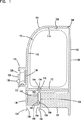
今、図1を参照する。石鹸供給装置100の1つの考えうる実施例が図解されている。石鹸供給装置の代替実施例は、1998年6月11日に出願され、“データ収集と表示能力を備えた使用法の優れたハンド・ソープ供給装置”と題された米国特許出願第09/096,079号に説明されており、その開示はこれに組み入れられている。
【0012】
石鹸供給装置100は、後部搭載板102およびカバー104を有する。後部搭載板102は、壁または他の適切な平面に、ねじ、クリップ、鉤のような留め金具または接着テープで取り付けることができる。カバー104は、回転軸106にて搭載板102の上部に取り付けられ、回転軸を中心に回転して開くことができる。カバー104は、石鹸のプラスチック貯蔵バッグ110が格納される貯蔵空間108の輪郭を定める。図中ではバッグ110が示されるが、他の実施例には、貯蔵空間108に挿入されるカートリッジのような他の貯蔵器の種類を含むことも可能である。代替的に、それ自身が貯蔵器の役割を果たす貯蔵空間108に、石鹸または他の液体を直接注ぐことが可能である。
【0013】
カバー104は、下部112、上部114および正面部116を有する。下部112は穴118の境界を定める。小ハウジング120は、カバー104の正面部116から伸びて、電子装置用空間122の輪郭を定める。ハウジング120は、前面124を有する。後でさらに詳細に記載する電子装置126は、電子装置用空間122内部に位置し、液晶ディスプレイ(LCD)128および押ボタン式インターフェース130に電気的に接続されている。LCD128およびインターフェース130は、利用者とのやりとりのためにハウジング120の正面部116に搭載されている。電子装置126がバッテリー駆動であれば、ハウジング120は、電池の充電のため、電子装置用空間122への図示されない通路を設ける。ハウジング120は、水、石鹸およびその他の環境危険から電子装置126を保護するために密閉される。
【0014】
突起131は、搭載板102の下部に形成され、カバー104の下に位置している。突起130は、第1の垂直の圧力面132を形成する。押板134は、回転軸を中心にして回転するようにカバー104の下部112に搭載されている。押板134は、正面136および背面138を有する。第2の垂直の圧力面142を形成するブロック140は、押板134の背面138に搭載される。押板134、ブロック140および第2の圧力面142は、石鹸を供給するためのアクチュエーターを形成する。
【0015】
第2の圧力面142は、第1の圧力面132に向かい合っている。第1の圧力面132および第2の圧力面142は、後でさらに詳細に記載する供給チューブ144に通路を提供するために一定の間隔を開けられる。第1の圧力面132および第2の圧力面142は、カバー104の下部112に形成される穴118の下方かつ反対側に位置している。
【0016】
マイクロ・スイッチ146のようなセンサーは、第2の圧力面142に搭載されており、第1の圧力面132に向かい合う可動接点またはアクチュエーター148を有する。この構成では、石鹸を供給するために利用者が押板134を押したとき、可動接点148が第1の圧力面132とかみ合い、マイクロ・スイッチ146を作動させることになる。マイクロ・スイッチ146は、図示されない導線により電子装置126と電気的な通信を行う。
【0017】
石鹸を保管する交換可能な貯蔵バッグ110は、貯蔵空間108の内部に位置する。供給チューブ144は、下端150、上端152、管内部154を有し、穴118を通り第1および第2の圧力面132および142の間に伸びている。供給チューブ144は、貯蔵バッグ110と流体のやりとりを行い、貯蔵バッグ110の底から伸びている。供給チューブ144の下端150は、第1の圧力面132および第2の圧力面142の下方にぶら下げられる。
【0018】
上部一方向バルブ156は管内部154の内部に位置し、供給チューブ144の上端152に近接する。上部一方向バルブ156は、第1の押板132および第2の押板142の上方に位置し、貯蔵バッグ110から管内部154へ石鹸が流れるように方向が合わせられている。下部一方向バルブ158は、管内部154の内部に位置し、供給チューブ144の下端150に近接する。下部一方向バルブ158は第1の押板132および第2の押板142の下方に位置し、供給チューブ144の下端150から石鹸が流れ出るように方向が合わせられている。使用中は、労働者が押板を押したとき、第1および第2の圧力面が協力して供給チューブ144を圧搾し、下部一方向バルブ158を通して末端の外へ石鹸を押し進める。
【0019】
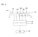
今、図2を参照する。電子装置126はマイクロ・コントローラー200、マイクロ・スイッチ146、LCD128およびマイクロ・コントローラー200と電気的に通信を行う押ボタン式インターフェース130を含んでいる。押ボタン式インターフェース130は4個の押ボタン・スイッチ202a−202dを有し、その各々がそれぞれ番号1−4のラベルが貼られている。他の実施例では、異なる形式または大きさのキー・パッドを使用することもできる。
【0020】
電子装置126は、図示されない電圧調整器に電気的に接続されている9V電池によって電力が供給されており、これは技術的によく知られている構成である。マイクロ・コントローラー200には、後述されるように電子装置126の動作を制御するプログラムが読み込まれる。1つの考えうる実施例では、LCD128は1行×8列文字ディスプレイ・モジュール、そしてマイクロ・コントローラー200はインテル社製8051型である。他の考えうる実施例では、マイクロ・コントローラー200、LCD128および押ボタン式インターフェース130は、マイクロチップ社製のマイクロチップPICシリーズのような、バッテリー動作に適した低コストの単一部品またはパッケージに一体化される。他の考えうる実施例では、マイクロ・コントローラー200は、適したメモリーが組み込まれているマイクロ・コントローラー、マイクロ・プロセッサーと適したメモリー、または適したプロセッサーに置き換えることができる。このような全ての実施例において、どれでも適切なコンピュータ言語によって、コードがプログラムされる。
【0021】
次のフローチャートの記載の中で明らかになるように、マイクロ・コントローラー200内部のメモリーは、押ボタン・スイッチ202a−202dの一意の順序に対応する労働者ごとのIDコードを記憶する。マイクロ・コントローラー200により実行されるプログラムは、「供給カウント」、「報賞カウント」、「乱数」、「中間数値」および「中間」という名称の一組の変数を使用する。「供給カウント」とは、特定の労働者が石鹸供給装置を使用した回数である。「供給カウント」には複数の数値があり、それぞれの数値が特定のIDコードに関連付けられている。「報賞カウント」とは、ある労働者が報賞を受けるために石鹸を供給しなければならない回数である。「乱数」とは、1から31までのような所定の範囲の中で、でたらめに生成された数である。「中間数値」は、所定の数値のうち1つが指定される。1つの考えうる実施例では、「中間数値」には34、84または184のいずれかが指定される。「中間」は「中間数値」を決定するために使用される。
【0022】
「報賞カウント」は、次の方程式によって決定される。
「報賞カウント」 = 「中間数値」 + 「乱数」
上述の数値を利用した1つの実施例では、この計算は「報賞カウント」が3つの所定の範囲である35から65、85から115または185から215のいずれか1つの中にあることを定める。それぞれの労働者に対して、「報賞カウント」の数値がこれらの範囲の1つに収まる。この構成の利点は、「報賞カウント」を予測するのがより困難になることであり、それが「報賞カウント」に到達するために繰り返し石鹸を供給しようとする、労働者の動機を減少する。
【0023】
なお、これらの計算は、本発明の1つの考えうる実施例にすぎない。例えば、他の実施例では、変数「中間数値」にさらに数値を与えて乱数性を強める、または変数「乱数」のとりうる数値としてより大きい範囲を与えて乱数性を強めることによって、可能な「報賞カウント」として様々な範囲を使用する。さらに他の考えうる実施例では「報賞カウント」を決定するのに直接乱数発生器を使用することもできる。
【0024】
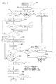
今、図3Aから3Cを参照する。起動されると同時に、プログラムは最初にマイクロ・コントローラー200内部のウォッチ・ドッグ・タイマーがリセットされたどうかを判断する(ブロック300)。もしウォッチ・ドッグ・タイマーがリセットされていれば、プログラムの実行は入力を読むためのコードに自動的にジャンプする(ブロック316)。そうでなければ、プログラムは変数を初期化して適切な診断ルーチンを実行する時点で、その初期化を通過する(ブロック302)。その後、プログラムはソフトウェアの現在のバージョンを8秒間表示する(ブロック304および306)。プログラムは、ディスプレイをクリアし(ブロック308)、スリープ・モード(ブロック310)に入る。スリープ・モードの間は、マイクロ・コントローラー200は、エネルギーを蓄え、押ボタン・スイッチ202a−202dが押されることにより始動する割込み検知を待つ状態に入る(ブロック312)。
【0025】
マイクロ・コントローラー200は、割込みを受信すると同時にスリープ・モードから目覚め(ブロック314)、そして、202a−202dのどの押ボタン・スイッチが作動されたかを判断するために入力を読み込む(ブロック316)。入力を読み込むと同時に、プログラムはバッテリー残量低下入力がアクティブかどうかを判断する(ブロック318)。アクティブの場合は、プログラムはおよそ3秒間LCD128上に“LOW BAT”と表示する(ブロック320および322)。
【0026】
プログラムは、押ボタン・スイッチ202a−202dが1個だけ押されたかそれ以上押されたかを判断する(ブロック324)。2個以上の押ボタン・スイッチ202a−202dが同時に押されたときは、プログラムはこれらのスイッチ202a−202dが、サービス・モードに入るために要求される所定のコードと一致するかどうかを判断する(ブロック326)。所定のスイッチ202a−202dの組合せが押されたときは、プログラムは、後でさらに詳細に記載されるサービス・モードに入る(ブロック328)。例えばサービス・モードに入るコードは、1と4で設定されるかもしれない。利用者が第1の押ボタン・スイッチ202aおよび第4の押ボタン・スイッチ202dを同時に押すと、プログラムはサービス・モードに入る。もし、前記コードと一致しない2つの押ボタン・スイッチ202a−202dが同時に押された場合は、LCD146がクリアされ(ブロック330)、レジスタおよび一時的変数がクリアされ(ブロック332)、そしてマイクロ・コントローラー200はスリープ・モードに入る(ブロック310)。
【0027】
サービス・モードでは、雇用者は報賞プログラムを有効または無効にする、「中間数値」を変更する、各々の労働者に関連付けられた「供給カウント」の値を見る、および「供給カウント」の値をクリアするといった機能を実行することができる。サービス・モードは後でさらに詳細に記載される。
【0028】
押ボタン・スイッチ202a−202dの1個だけが押された場合(ブロック324)、マイクロ・コントローラーは、押ボタン・スイッチ202a−202dに対応した第1のIDの数字を保存し、LCD146上にそのIDの数字を表示する(ブロック334)。例えば、もし第2の押ボタン・スイッチ202bが押されると、プログラムは数字2を保存して、LCD146上に数字2を表示する。押ボタン・スイッチ202bが放されたとき(ブロック336)、プログラムは、8秒間のタイムアウト待ち時間に入る(ブロック338)。もし第2の押ボタン・スイッチ202a−202dが押される前に8秒間が経過すると、LCD146はクリアされ(ブロック340)、レジスタおよび一時的変数はクリアされ、(ブロック342)、そしてマイクロ・コントローラー200はスリープ・モードに入る(ブロック310)。
【0029】
8秒間のタイムアウト待ち時間に、第2の押ボタン・スイッチ202bが連続して入力されると(ブロック344)、プログラムは、第2の押ボタン・スイッチ202b(ブロック346)に対応したIDの数字をレジスタに保存する。IDの第2の数字は、第1の数字と同じことがあり得る。第2の押ボタン・スイッチ202bが放されたとき(ブロック348)、押された2つの押ボタン・スイッチに対応する第1および第2のIDの数字がLCD146上に表示される(ブロック350)。プログラムは、そのIDに対応する「供給カウント」もまたLCD146上に表示する(ブロック350)。「供給カウント」の現在値は、前記表示されたIDが入力されかつ石鹸が石鹸供給装置100から供給された回数である。
【0030】
2桁のIDコードが入力された後、プログラムはマイクロ・スイッチ146が閉じられているかどうか(それは石鹸が供給されていることを示す)を判断するための8秒間のタイムアウト待ち時間に入る(ブロック352)。もしマイクロ・スイッチ146が閉じられることなく8秒間のタイムアウト時間が経過したときは、LCD146はクリアされ(ブロック354)、レジスタおよび一時的変数はクリアされる(ブロック356)、そして、マイクロ・コントローラー200は、スリープ・モードに入る(ブロック310)。8秒間のタイムアウト時間が経過する前にマイクロ・スイッチ146が閉じられると(ブロック358)、現在のIDコードの「供給カウント」の現在値が1つ増加する(ブロック360)。報賞が有効な場合は(ブロック362)、現在のIDコードが表示され、そのIDコードの増加された「供給カウント」の数値がLCD146上に8秒間表示される(ブロック364および366)。8秒間のタイムアウト時間を経過すると、LCD146はクリアされ(ブロック368)、レジスタおよび一時的変数はクリアされる(ブロック370)、そして、マイクロ・コントローラー200は、スリープ・モードに入る(ブロック310)。
【0031】
報賞プログラムが有効なときは(ブロック362)、プログラムは「供給カウント」=「報賞カウント」であるかどうか判断する(ブロック372)。2つの数値が等しくない場合は、プログラムは、現在のIDコードおよび関連付けられた増加された「表示カウント」を8秒間表示する(ブロック364および366)。LCD146はクリアされ(ブロック368)、レジスタおよび一時的変数はクリアされる(ブロック370)、そして、マイクロ・コントローラー200は、スリープ・モードに入る(ブロック310)。「供給カウント」=「報賞カウント」の場合は(ブロック372)、プログラムはLCD146上に“WINNER”と表示する(ブロック374)。
【0032】
その後、プログラムは雇用者が第1の押ボタン・スイッチ202aおよび第2の押ボタン・スイッチ202b、または、何か他に所定のスイッチ202a−202dの組合せを、お互いに2秒以内に押されるのを待つ(ブロック376および378)。これらの押ボタン・スイッチ202aおよび202bがお互いに2秒以内に押されなければ、現在のIDコードおよび関連付けられた「供給カウント」の数値がLCD146上に表示される(ブロック380)。追加の2秒間にこれらの押ボタン・スイッチ202aおよび202bが押されなければ(ブロック382および384)、プログラムはLCD146上に“WINNER”と表示する(ブロック374)。その後プログラムは、現在のIDコードおよび「供給カウント」の表示が“WINNER”の語の表示と交互に起こるループに入る(ブロック374−384)。第1の押ボタン・スイッチ202aおよび第2の押ボタン・スイッチ202bが最終的に押されると、プログラムは「供給カウント」の数値をクリアし(ブロック386)、「乱数」および「報賞カウント」を再計算する(ブロック388)。その後LCD146がクリアされ(ブロック386)、レジスタおよび一時的変数がクリアされ(ブロック370)、およびマイクロ・コントローラー200は、スリープ・モードに入る(ブロック310)。
【0033】
そして、「報賞カウント」に反映する目標が全ての労働者に対してリセットされ、彼らは“WINNER”になるという要望のためにやり直さなければならない。この実施例では、労働者は「報賞カウント」に達するためにお互い競争し合う。代替実施例では、個々の労働者は自分の「報賞カウント」を有しており、従って互いにではなく自分自身と競争する。
【0034】
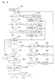
今、図4を参照する。プログラムがサービス・モードに入っているとき(ブロック328)、プログラムはLCD146上に“Mode”という語を表示する(ブロック400)。プログラムは、全ての押ボタン・スイッチ202a−202dが放されるまで待ち状態に入る(ブロック402)。全ての押ボタン・スイッチ202a−202dが放された後、プログラムはいずれかの押ボタン・スイッチ202a−202dがその後に押されるかどうか判断するために、入力を読み取る(ブロック404)。プログラムは、8秒間入力を読み取る(ブロック422)。押ボタン・スイッチ202a−202dが押されていなければ、LCD146がクリアされ(ブロック424)、レジスタおよび一時的変数がクリアされ(ブロック426)、およびマイクロ・コントローラー200は、スリープ・モードに入る(ブロック310)。
【0035】
8秒間のタイムアウト時間内に第1の押ボタン・スイッチ202aが押された場合(ブロック406)、プログラムは回数読み出しモードに入る(ブロック408)。このモードでは、プログラムは各々のIDコードおよびそれに関連付けられた「供給カウント」の値をLCD146上に表示する。プログラムは、IDコード及びそれに関連付けられた「供給カウント」の表示により索引をつける。第2の押ボタン・スイッチ202bが押された場合(ブロック410)、プログラムはカウンター消去モードに入る(ブロック412)。このモードでは、プログラムはIDコードに割り当てられている変数「供給カウント」の全ての数値を自動的にクリアする。第3の押ボタン・スイッチ202cが押された場合(ブロック414)、プログラムは報賞有効化モードに入る(ブロック416)。報賞有効化モードに関しては、後でさらに詳細に記載する。第4の押ボタン・スイッチ202dが押された場合(ブロック418)、プログラムは中間設定モードに入り(ブロック420)。これについても、後でさらに詳細に説明する。それぞれのプログラム・モード(ブロック408、412、416および420)が完了すると、LCD146がクリアされ、レジスタおよび一時的変数がクリアされ、およびマイクロ・コントローラー200はスリープ・モードに入る。
【0036】
図5を参照する。プログラムが報賞有効化モードに入ると(ブロック416)、プログラムは最初にディスプレイをクリアし(ブロック500)、そして直ちに報賞モードが現在有効になっているかどうか判断する(ブロック502)。プログラムは、報賞モードが有効になっていると判断した場合は(ブロック502)、初めにLCD146上に“Rwd Y”というメッセージを表示し(ブロック518)、そして乱数アルゴリズムを実行して、「乱数」の値を生成する。乱数アルゴリズム(ブロック520−526)は、報賞有効化モードに入るために、雇用者が第3の押ボタン・スイッチ(ブロック414)を押している間に実行される。乱数アルゴリズム(ブロック520−526)は、乱数の現在値を減算する方程式
「乱数」=「乱数」−1
によって「乱数」を計算する(ブロック520)。「乱数」=0ならば(ブロック522)、プロセッサーは自動的に「乱数」=31にリセットする(ブロック524)。したがって、乱数アルゴリズムは全ての押ボタン・スイッチが放されるまで(ブロック526)ループを回って「乱数」を減算し続ける(ブロック520−524)。乱数アルゴリズム(ブロック520−526)は、報賞有効化モード(ブロック416)に入るために第3の押ボタンが押されたときは必ず、自動的に1から31の数値の間の乱数を生成する。
【0037】
プログラムが報賞モードが有効でないと判断すると(ブロック502)、プログラムは初めにLCD146上に“Rwd N”というメッセージを表示する(ブロック504)。その後プログラムは、押ボタン・スイッチ202a−202dのいずれかが押されているかどうか判断するために、入力を読み込む(ブロック506)。第3の押ボタン・スイッチ202cが、8秒間以内に(ブロック508および510)押された場合には、プログラムは、報賞モードが有効かどうか再度判断する(ブロック512)。報賞プログラムが有効の場合は、プログラムは報賞プログラムを無効にする(ブロック514)。報賞プログラムが有効でない場合は、プログラムは報賞プログラムを有効にし(ブロック516)、上述のように乱数アルゴリズムを実行し(ブロック520−526)、報賞回数を計算する(ブロック528)。この構成では、報賞モードを切り替えるために押されている押ボタン・スイッチ(ブロック508)は、報賞有効化モードに入るために使用される押ボタン・スイッチと同じである(ブロック414)。
【0038】
「報賞カウント」の数値を「報賞カウント」の自動生成に基づかせると、乱数性の水準を維持することに役立つので、労働者(および雇用者)は、いつ従業者が報賞の権利を与えられるか予測することができない。この乱数性は、従業者が繰り返し石鹸供給装置を作動させることにより、報賞プログラムの裏をかこうとすることを思い止まらせる。
【0039】
他の実施例では、雇用者は報賞有効化モードに入り、第3の押ボタン以外の押ボタン、または複数のスイッチを使用することにより、有効状態および無効状態のどちらかに切り替える。さらなる他の可能な実施例では、雇用者が報賞有効化モードに入り、様々な複数の押ボタンを使用することによって報賞モードを有効状態および無効状態のどちらかに切り替えるようプログラムされている。またさらなる他の考えうる実施例では、雇用者は手入力により「報賞カウント」を入力できる。
【0040】
第3の押ボタン・スイッチ202cが作動させられずに8秒間が経過した場合は(ブロック510)、LCD146がクリアされ(ブロック530)、レジスタおよび一時的変数がクリアされ(ブロック532)、およびマイクロ・コントローラー200はスリープ・モードに入る(ブロック310)。その結果、報賞有効化モードを終了する。
【0041】
図6を参照する。雇用者が第4の押ボタン・スイッチ202dを押すと、上述の中間設定モードに入る(ブロック420)、プログラムは直ちに変数「中間」の現在の数値を判断する(ブロック600,606,612)。「中間」=50のとき(ブロック600)、プログラムは“MN=50”のメッセージをLCD146上に表示し(ブロック602)、「中間数値」=34に設定する(ブロック604)。「中間」=100のとき(ブロック606)、プログラムは“MN=100”のメッセージをLCD146上に表示し(ブロック608)、「中間数値」=84に設定する(ブロック610)。「中間」=200のとき(ブロック612)、プログラムは“MN=100”のメッセージをLCD146上に表示し(ブロック614)、「中間数値」=184に設定する(ブロック616)。
【0042】
「中間数値」を設定した後(ブロック604,610,616)、プログラムは、第4の押ボタン・スイッチ202dがまだ押されているかどうか、または第4の押ボタン・スイッチが再度押された(ブロック618)かどうかを判断するために、8秒間(ブロック622)入力を読み込む(ブロック618)。第4の押ボタン・スイッチ202dが押されている場合には(ブロック620)、プログラムは再度、変数「中間」の現在値(ブロック624,626および628)を判断する。「中間」=50のときは(ブロック624)、プログラムは「中間」=100に設定する(ブロック630)。「中間」=100のときは(ブロック626)、プログラムは「中間」=200に設定する(ブロック632)。「中間」=200のときは(ブロック628)、プログラムは「中間」=50に設定する(ブロック634)。その後、プログラムは先頭に戻り、新しく割り当てられた「中間」の数値(ブロック600、606および612)に依存した「中間数値」の数値を再度割り当てる(ブロック604、610および616)。
【0043】
中間設定モード内のこのループ(ブロック420)は、自動的に「中間数値」を再度割り当て、そして「中間数値」は、上述のように「報賞カウント」の計算に用いられる。それゆえ「報賞カウント」には、もう1つ乱数性の要素が付け加えられる。「中間数値」=34のとき、「報賞カウント」の数値は、35から65の間である。「中間数値」=84のとき、「報賞カウント」の数値は、85から115の間である。「中間数値」=184のとき、「報賞カウント」の数値は、185から215の間である。ここでは一定の範囲の例が示されているが、他の実施例では他の範囲が含まれるものとする。さらなる他の実施例では、雇用者が手入力で「報賞カウント」が取りうる数値の範囲を設定できる。
【0044】
8秒間が経過した後(ブロック622)、LCD146がクリアされ(ブロック636)、レジスタおよび一時的変数がクリアされ(ブロック638)、およびマイクロ・コントローラー200はスリープ・モードに入る(ブロック310)。
【0045】
様々な実施例および方法の記載が完全に特定されているが、本発明の精神を逸脱することなく、修正を行うことができることは予期される。従って、本発明の範囲は、前記の様々な実施例および方法の記載によってではなく、添付された請求項によって規定されることが意図される。
【図面の簡単な説明】
【図1】 本発明を実施した石鹸供給装置の側面の断面図を示す。
【図2】 図1に示した石鹸供給装置に含まれる電子装置の略図を示す。
【図3】 図2に示した電子装置を制御する、1つの考えうるプログラムを説明するフローチャートを示す。
【図4】 図2に示した電子装置を制御する、1つの考えうるプログラムを説明するフローチャートを示す。
【図5】 図2に示した電子装置を制御する、1つの考えうるプログラムを説明するフローチャートを示す。
【図6】 図2に示した電子装置を制御する、1つの考えうるプログラムを説明するフローチャートを示す。[0001]
(Technical field)
The present invention relates to a hand soap dispenser, and more particularly to a hand soap dispenser that tracks usage for a reward program that actively enhances hygiene and hygiene.
[0002]
(Background of the Invention)
Like businesses in other aspects of the hospitality industry, businesses in the food service industry are keenly aware of the need for employees to maintain clean sanitation. Frequent worker cleansing of their hands is important in providing customers with safe and hygienic foods and dishes. It is important to ensure that the workers clean their hands afterwards, especially when using the bathroom, taking a smoking break, working with cleaning tools and other chemicals.
[0003]
It is important to maintain clean sanitation. This is because a lot of contamination sprinkled on food can cause illness to customers who have eaten it. For example, workers who do not wash their hands after using a washroom may sprinkle excreta bacteria in the food they handle. If this bacterium is ingested, it can lead to serious illness or even death. Other types of bacteria and contamination can cause human disease as well. If a customer gets sick because of poor hygiene or contaminated food, it can result in bad reputation and business loss. Similarly, making a customer sick can expose the business to litigation and financial responsibility.
[0004]
Employers have tried a variety of devices that encourage workers to clean their hands. Examples of these technologies include an electronic device that tracks the number of times soap is dispensed from the dispenser, and a mechanism that sounds an alarm if the bathroom door is opened before soap is dispensed from the dispenser. ing. The difficulty with these devices is that they rely on hostile enhancements to maintain compliance with hygiene standards. If such equipment is not properly managed, it can create a distrustful environment for workers or cause workers to resist compliance with hygiene standards. Another approach to promoting good hygiene is to make it easier to wash hands with a feeder that automatically supplies soap. The difficulty with these devices is that they cannot be clearly promoted, monitored or enforced.
[0005]
Therefore, there is a need for a soap dispenser that constructively strengthens compliance with hygiene standards. In this context, there is a need for a soap dispenser that allows a program that rewards workers for good hygiene practices. Similarly, there is a need for a soap dispenser that requires the employer to approve the worker's compliance with hygiene standards.
[0006]
(Summary of the Invention)
One embodiment of the present invention is directed to a system for rewarding and encouraging adherence to personal hygiene standards predetermined in a hygiene compliance program. The system includes a liquid supply device that includes an actuator. A sensor is connected to the actuator. A processor in electrical communication with the sensor is configured to increment the count when the sensor is activated, associate the count with an identification code, and compare the count to a predetermined number.
[0007]
Another embodiment of the present invention is directed to a method for rewarding and encouraging adherence to personal hygiene standards predetermined in a hygiene compliance program. The method utilizes an electric liquid supply device. The method inputs a unique identification code, activates the liquid supply, senses activation of the supply mechanism, and counts corresponding to the number of times the liquid supply is operated based on the unique identification code. And displaying a signal when the count is equal to a predetermined number.
[0008]
(Detailed explanation)
The present invention will first be described in general terms. Reference will now be made in detail to various embodiments of the invention, including preferred embodiments, with reference to the drawings, in which reference numerals indicate the parts and the parts collection throughout the various views. Reference to the described embodiments does not limit the scope of the invention, but only by the scope of the appended claims.
[0009]
Generally speaking, the present invention is directed to a supply device that allows a human to input an identification code. The feeding device continues to manage the total number of uses of the human feeding device and periodically displays a reward for approving that a person has used the feeding device. In one possible embodiment, the supply device is a soap supply device useful for maintaining clean hygiene in restaurants and other hospitality facilities.
[0010]
The present invention has various advantages. For example, frequent use of the supply device is noticeable to the employer. Employers can then use the supply device as part of an incentive program for employees that encourages adherence to high hygiene and cleanliness standards. This advantage is particularly important in view of the growing number of people and families who eat at restaurants or rely on processed foods. These people are increasingly exposed to the dangers of contaminated food, and many of them can be prevented if food handlers simply wash their hands and maintain clean hygiene . The present invention can also be used with other supervisory methods that put hygiene practices into a more constructive way of thinking. These and other advantages will be apparent from the description below.
[0011]
Reference is now made to FIG. One possible embodiment of the
[0012]
The
[0013]
The
[0014]
The
[0015]
The
[0016]
A sensor, such as a
[0017]
A
[0018]
The upper one-
[0019]
Reference is now made to FIG. The
[0020]
The
[0021]
As will become apparent in the description of the following flowchart, the memory within the micro-controller 200 stores an ID code for each worker corresponding to the unique order of the pushbutton switches 202a-202d. The program executed by the
[0022]
The “reward count” is determined by the following equation.
“Reward Count” = “Intermediate Number” + “Random Number”
In one embodiment utilizing the above-described numerical values, this calculation determines that the “reward count” is within one of three predetermined ranges of 35 to 65, 85 to 115, or 185 to 215. For each worker, the “Reward Count” number falls within one of these ranges. The advantage of this configuration is that it is more difficult to predict the “reward count”, which reduces the worker's motivation to repeatedly supply soap to reach the “reward count”.
[0023]
Note that these calculations are only one possible embodiment of the invention. For example, in another embodiment, it is possible to increase the randomness by giving a numerical value to the variable “intermediate numerical value”, or to increase the randomness by giving a larger range as a numerical value that the variable “random number” can take. Various ranges are used as "reward counts". In yet another possible embodiment, a random number generator can be used directly to determine the “reward count”.
[0024]
Reference is now made to FIGS. 3A to 3C. Upon activation, the program first determines whether the watch dog timer within the
[0025]
[0026]
The program determines whether only one pushbutton switch 202a-202d has been pressed or more (block 324). When two or more pushbutton switches 202a-202d are pressed simultaneously, the program determines whether these switches 202a-202d match the predetermined code required to enter service mode. (Block 326). When a given switch 202a-202d combination is pressed, the program enters a service mode which will be described in more detail later (block 328). For example, the code to enter service mode may be set at 1 and 4. When the user simultaneously presses the first pushbutton switch 202a and the
[0027]
In service mode, the employer enables or disables the award program, changes the “intermediate value”, sees the value of “supply count” associated with each worker, and sets the value of “supply count”. Functions such as clearing can be executed. The service mode will be described in more detail later.
[0028]
If only one of the pushbutton switches 202a-202d is pressed (block 324), the microcontroller stores the number of the first ID corresponding to the pushbutton switch 202a-202d and displays it on the
[0029]
When the
[0030]
After the two-digit ID code is entered, the program enters an 8-second timeout period to determine if the
[0031]
If the award program is valid (block 362), the program determines whether “supply count” = “award count” (block 372). If the two numbers are not equal, the program displays the current ID code and the associated increased “display count” for 8 seconds (blocks 364 and 366).
[0032]
Thereafter, the program allows the employer to press the first pushbutton switch 202a and the
[0033]
And the goal reflected in the “reward count” is reset for all workers and they must redo for the desire to become “WINNER”. In this example, workers compete with each other to reach the “reward count”. In an alternative embodiment, individual workers have their own “reward count” and thus compete with themselves rather than each other.
[0034]
Reference is now made to FIG. When the program is in service mode (block 328), the program displays the word “Mode” on the LCD 146 (block 400). The program waits until all pushbutton switches 202a-202d are released (block 402). After all pushbutton switches 202a-202d are released, the program reads the input to determine whether any pushbutton switches 202a-202d are subsequently depressed (block 404). The program reads the input for 8 seconds (block 422). If pushbutton switches 202a-202d are not pressed,
[0035]
If the first pushbutton switch 202a is pressed within the eight second timeout period (block 406), the program enters a number read mode (block 408). In this mode, the program displays on the
[0036]
Please refer to FIG. When the program enters reward enable mode (block 416), the program first clears the display (block 500) and immediately determines whether the reward mode is currently enabled (block 502). If the program determines that the reward mode is enabled (block 502), it first displays the message “Rwd Y” on the LCD 146 (block 518) and executes the random number algorithm to “random number” Is generated. The random number algorithm (blocks 520-526) is executed while the employer is pressing the third pushbutton switch (block 414) to enter the reward validation mode. The random number algorithm (blocks 520-526) is an equation that subtracts the current value of the random number.
“Random number” = “Random number” −1
To calculate a “random number” (block 520). If “random number” = 0 (block 522), the processor automatically resets to “random number” = 31 (block 524). Accordingly, the random number algorithm continues to subtract “random numbers” around the loop until all pushbutton switches are released (block 526) (blocks 520-524). The random number algorithm (block 520-526) automatically generates a random number between 1 and 31 whenever the third pushbutton is pressed to enter the reward validation mode (block 416). .
[0037]
If the program determines that the reward mode is not valid (block 502), the program first displays the message “Rwd N” on the LCD 146 (block 504). The program then reads the input to determine if any of the pushbutton switches 202a-202d are being pressed (block 506). If the third pushbutton switch 202c is pressed within 8 seconds (blocks 508 and 510), the program again determines whether the reward mode is enabled (block 512). If the reward program is valid, the program disables the reward program (block 514). If the award program is not valid, the program validates the award program (block 516), executes the random number algorithm as described above (block 520-526), and calculates the number of awards (block 528). In this configuration, the pushbutton switch being pressed to switch the award mode (block 508) is the same as the pushbutton switch used to enter the award enabling mode (block 414).
[0038]
Based on the automatic generation of the “reward count” number from the “reward count”, it helps to maintain a level of randomness so that workers (and employers) are entitled to rewards when employees I ca n’t predict. This randomness discourages employees from trying to reverse the reward program by repeatedly operating the soap dispenser.
[0039]
In another embodiment, the employer enters the reward validation mode and switches between the enabled state and the disabled state by using a push button other than the third push button, or a plurality of switches. In yet another possible embodiment, the employer is programmed to enter the reward enable mode and switch the reward mode to either the enabled or disabled state by using various pushbuttons. In yet another possible embodiment, the employer can enter the “reward count” manually.
[0040]
If 8 seconds have elapsed without the third pushbutton switch 202c being actuated (block 510), the
[0041]
Please refer to FIG. When the employer presses the
[0042]
After setting the “intermediate value” (blocks 604, 610, 616), the program determines whether the
[0043]
This loop (block 420) in the intermediate setting mode automatically reassigns the “intermediate value” and the “intermediate value” is used to calculate the “reward count” as described above. Therefore, another element of randomness is added to the “reward count”. When “intermediate numerical value” = 34, the numerical value of “reward count” is between 35 and 65. When “intermediate numerical value” = 84, the numerical value of “reward count” is between 85 and 115. When “intermediate numerical value” = 184, the numerical value of “reward count” is between 185 and 215. Although an example of a certain range is shown here, it is assumed that other ranges are included in other embodiments. In still another embodiment, the employer can set a range of numerical values that the “reward count” can take manually.
[0044]
After 8 seconds have elapsed (block 622),
[0045]
While various embodiments and method descriptions have been fully identified, it is anticipated that modifications can be made without departing from the spirit of the invention. Accordingly, the scope of the invention is intended to be defined by the appended claims rather than by the foregoing description of various embodiments and methods.
[Brief description of the drawings]
FIG. 1 shows a side sectional view of a soap supply apparatus embodying the present invention.
2 shows a schematic diagram of an electronic device included in the soap supply apparatus shown in FIG.
FIG. 3 shows a flowchart describing one possible program for controlling the electronic device shown in FIG.
FIG. 4 shows a flow chart describing one possible program for controlling the electronic device shown in FIG.
FIG. 5 shows a flow chart describing one possible program for controlling the electronic device shown in FIG.
FIG. 6 shows a flowchart describing one possible program for controlling the electronic device shown in FIG.
Claims (21)
利用者の一意の識別コードを入力し、
前記個人衛生用の液体供給器を作動させ、
前記個人衛生用の液体供給器の作動を感知し、
入力された前記一意の識別コードに基づき前記個人衛生用の液体供給器が作動された回数に対応するカウントを増やし、
前記カウントが所定の数と等しいときに合図を表示し、および
報奨を前記の対応する所定の数に関連付ける
方法。A method of rewarding and encouraging compliance with the personal hygiene standards pre-determined in the hygiene compliance program, using an electric personal hygiene liquid supply,
Enter a unique identification code for the user,
Actuate the liquid supply for personal hygiene,
Sensing the operation of the liquid supply for personal hygiene ,
Increase the count corresponding to the number of times that the personal hygiene fluid dispenser has been activated based on the unique identification code entered;
Displaying a cue when the count is equal to a predetermined number, and associating a reward with the corresponding predetermined number.
アクチュエーターを含んだ個人衛生用の液体供給器、
前記アクチュエーターに接続されたセンサー、
前記センサーと電気的に通信を行い、前記アクチュエーターを作動させたときにカウントを増やし、前記カウントを識別コードと関連づけ、および前記カウントを所定の数と比較し、前記カウントが前記所定の数と等しいときにメッセージを生成するように構成されたプロセッサー、および
前記メッセージを表示するディスプレイを備えた、システム。A system for rewarding and encouraging adherence to personal hygiene standards predetermined in a hygiene compliance program,
Personal hygiene fluid supply, including actuator
A sensor connected to the actuator;
In electrical communication with the sensor, when the actuator is actuated, the count is increased, the count is associated with an identification code, and the count is compared with a predetermined number, the count being equal to the predetermined number A system comprising a processor configured to generate a message from time to time, and a display for displaying the message.
Applications Claiming Priority (3)
| Application Number | Priority Date | Filing Date | Title |
|---|---|---|---|
| US09/458,478 US6542568B1 (en) | 1999-12-09 | 1999-12-09 | Soap dispenser having reward program |
| US09/458,478 | 1999-12-09 | ||
| PCT/US2000/033095 WO2001041612A1 (en) | 1999-12-09 | 2000-12-06 | Soap dispenser having reward program |
Publications (3)
| Publication Number | Publication Date |
|---|---|
| JP2003515413A JP2003515413A (en) | 2003-05-07 |
| JP2003515413A5 JP2003515413A5 (en) | 2008-01-31 |
| JP4523219B2 true JP4523219B2 (en) | 2010-08-11 |
Family
ID=23820942
Family Applications (1)
| Application Number | Title | Priority Date | Filing Date |
|---|---|---|---|
| JP2001542792A Expired - Lifetime JP4523219B2 (en) | 1999-12-09 | 2000-12-06 | Soap dispenser with reward program |
Country Status (8)
| Country | Link |
|---|---|
| US (1) | US6542568B1 (en) |
| EP (1) | EP1235506B1 (en) |
| JP (1) | JP4523219B2 (en) |
| AT (1) | ATE305742T1 (en) |
| AU (1) | AU775153B2 (en) |
| CA (1) | CA2389000C (en) |
| DE (1) | DE60023027T2 (en) |
| WO (1) | WO2001041612A1 (en) |
Cited By (4)
| Publication number | Priority date | Publication date | Assignee | Title |
|---|---|---|---|---|
| US10529219B2 (en) | 2017-11-10 | 2020-01-07 | Ecolab Usa Inc. | Hand hygiene compliance monitoring |
| USRE48951E1 (en) | 2015-08-05 | 2022-03-01 | Ecolab Usa Inc. | Hand hygiene compliance monitoring |
| US11272815B2 (en) | 2017-03-07 | 2022-03-15 | Ecolab Usa Inc. | Monitoring modules for hand hygiene dispensers |
| US11284333B2 (en) | 2018-12-20 | 2022-03-22 | Ecolab Usa Inc. | Adaptive route, bi-directional network communication |
Families Citing this family (53)
| Publication number | Priority date | Publication date | Assignee | Title |
|---|---|---|---|---|
| US6832916B2 (en) * | 2000-11-20 | 2004-12-21 | Venture Management Alliance, Llc | Soap dispenser hand wash interval timer |
| US8595055B2 (en) * | 2001-03-27 | 2013-11-26 | Points.Com | Apparatus and method of facilitating the exchange of points between selected entities |
| US7353373B2 (en) * | 2003-03-31 | 2008-04-01 | Sharp Laboratories Of America, Inc. | Intelligent printer installation |
| US7651989B2 (en) | 2003-08-29 | 2010-01-26 | Kimberly-Clark Worldwide, Inc. | Single phase color change agents |
| US7783380B2 (en) * | 2003-12-31 | 2010-08-24 | Kimberly-Clark Worldwide, Inc. | System and method for measuring, monitoring and controlling washroom dispensers and products |
| US20080021779A1 (en) * | 2004-12-31 | 2008-01-24 | Lynn John M | Entertaining or advertising hygiene apparatus |
| US20060287215A1 (en) * | 2005-06-17 | 2006-12-21 | Mcdonald J G | Color-changing composition comprising a thermochromic ingredient |
| US8502681B2 (en) * | 2005-06-20 | 2013-08-06 | Biovigil, Llc | Hand cleanliness |
| US7286057B2 (en) * | 2005-06-20 | 2007-10-23 | Biovigil Llc | Hand cleanliness |
| US7936275B2 (en) * | 2005-06-20 | 2011-05-03 | Biovigil, Llc | Hand cleanliness |
| US7616122B2 (en) * | 2005-06-20 | 2009-11-10 | Biovigil, Llc | Hand cleanliness |
| US8067350B2 (en) | 2005-12-15 | 2011-11-29 | Kimberly-Clark Worldwide, Inc. | Color changing cleansing composition |
| US20070142263A1 (en) * | 2005-12-15 | 2007-06-21 | Stahl Katherine D | Color changing cleansing composition |
| US20080031838A1 (en) * | 2006-08-03 | 2008-02-07 | Bolling Steven F | Tracing hand cleaner |
| US7617830B2 (en) * | 2006-10-31 | 2009-11-17 | Resurgent Health & Medical, Llc | Wash chamber for automated appendage-washing apparatus |
| US7659824B2 (en) * | 2006-10-31 | 2010-02-09 | Resurgent Health & Medical, Llc | Sanitizer dispensers with compliance verification |
| US7818083B2 (en) * | 2006-10-31 | 2010-10-19 | Resurgent Health & Medical, Llc | Automated washing system with compliance verification and automated compliance monitoring reporting |
| US7698770B2 (en) * | 2006-10-31 | 2010-04-20 | Resurgent Health & Medical, Llc | Automated appendage cleaning apparatus with brush |
| US20090089168A1 (en) * | 2007-01-10 | 2009-04-02 | Phyllis Adele Schneck | ACE (Alternative Currency Exchange): Alternative Currency Tracking and Mapping System and Method |
| US8261950B2 (en) | 2007-10-22 | 2012-09-11 | Georgia-Pacific Consumer Products Lp | Pumping dispenser |
| US20090224924A1 (en) * | 2008-03-10 | 2009-09-10 | Thorp Robert B | System and method for positively reinforcing hand-hygeine compliance |
| US20090273477A1 (en) * | 2008-04-29 | 2009-11-05 | Meritech, Inc. | Hygiene compliance monitoring |
| BR112012006609A2 (en) * | 2009-09-25 | 2019-09-24 | 3M Innovative Properties Co | system for monitoring hygiene practices, method for monitoring hygiene compliance and methods for selecting a hygiene protocol |
| CN102040033B (en) * | 2009-10-10 | 2012-10-03 | 上海宏曲电子科技有限公司 | Loop type pressed shifting device |
| US20110153349A1 (en) * | 2009-10-15 | 2011-06-23 | 3M Innovative Properties Company | Health care delivery monitoring systems and methods |
| US8717177B2 (en) * | 2010-01-11 | 2014-05-06 | Gojo Industries, Inc. | Hygiene compliance monitoring system |
| US8823525B2 (en) * | 2010-01-11 | 2014-09-02 | Gojo Industries, Inc. | Hygiene compliance monitoring system |
| US9000930B2 (en) | 2010-05-24 | 2015-04-07 | Georgia-Pacific Consumer Products Lp | Hand hygiene compliance system |
| US8427323B2 (en) | 2010-06-25 | 2013-04-23 | Pibed Limited | Monitoring system |
| US20120002510A1 (en) * | 2010-07-02 | 2012-01-05 | Berman Jr Carl R | System and apparatus for automatically ensuring the appropriate duration for handwashing |
| US9672726B2 (en) | 2010-11-08 | 2017-06-06 | Georgia-Pacific Consumer Products Lp | Hand hygiene compliance monitoring system |
| US20120245951A1 (en) * | 2011-03-23 | 2012-09-27 | Jonathan Peter Gips | System and method for compliance reward |
| US8786398B2 (en) * | 2011-03-28 | 2014-07-22 | Gojo Industries, Inc. | Dispenser with use-based content delivery |
| CA2737012C (en) * | 2011-04-08 | 2018-07-24 | Gotohti.Com Inc. | Personal compliance dispenser |
| US9262905B2 (en) * | 2011-04-27 | 2016-02-16 | Gojo Industries, Inc. | Portable compliance dispenser |
| US8651328B2 (en) | 2011-07-14 | 2014-02-18 | Georgia-Pacific Consumer Products Lp | Pumping dispenser shield |
| DE102012110405B4 (en) * | 2012-10-30 | 2015-07-02 | Joachim Götz | Dosing dispenser for hand cleansers and method for improving hygiene behavior in toilets |
| US9265384B2 (en) * | 2013-01-16 | 2016-02-23 | Gojo Industries, Inc. | Point-of-care compliance module |
| AU2014290458A1 (en) | 2013-07-19 | 2015-11-12 | Versus Technology, Inc. | Automatic hygiene compliance assistance |
| KR101462261B1 (en) * | 2013-08-14 | 2014-11-21 | 주식회사 프로텍 | Piezoelectric Dispenser Counting Operation Number |
| US10636321B2 (en) | 2014-07-02 | 2020-04-28 | Gojo Industries, Inc. | Methods and systems for improving hand hygiene |
| FR3025405B1 (en) * | 2014-09-04 | 2017-11-24 | Intuiskin | DEVICE FOR CONTAINING AND DISPENSING A COSMETIC SUBSTANCE |
| CA2865608C (en) | 2014-09-29 | 2021-06-15 | Op-Hygiene Ip Gmbh | Parallel hand hygiene compliance system |
| US10276029B2 (en) | 2014-11-13 | 2019-04-30 | Gojo Industries, Inc. | Methods and systems for obtaining more accurate compliance metrics |
| BR112017017815A2 (en) * | 2015-02-25 | 2018-04-10 | Kimberly-Clark Worldwide, Inc. | method and system for consumer reward program for use in sanitary facility |
| EP3278296A4 (en) | 2015-03-30 | 2018-10-31 | Kimberly-Clark Worldwide, Inc. | System and method for instructing personnel on washroom maintenance requirements |
| WO2016161318A1 (en) | 2015-04-01 | 2016-10-06 | Ecolab Usa Inc. | Flexible mounting system for hand hygiene dispensers |
| US11395566B2 (en) | 2016-04-11 | 2022-07-26 | Gpcp Ip Holdings Llc | Sheet product dispenser |
| US11412900B2 (en) | 2016-04-11 | 2022-08-16 | Gpcp Ip Holdings Llc | Sheet product dispenser with motor operation sensing |
| US10490057B1 (en) | 2017-01-11 | 2019-11-26 | Swipesense, Inc. | Hygienic sensor device, system, and method for monitoring hygienic dispenser usage and compliance |
| US11069220B2 (en) | 2017-07-10 | 2021-07-20 | Biovigil Hygiene Technologies, Llc | Hand cleanliness monitoring |
| US20220157441A1 (en) * | 2019-04-02 | 2022-05-19 | Essity Hygiene And Health Aktiebolag | Reward hygiene system |
| EP4280924A1 (en) | 2021-01-20 | 2023-11-29 | Ecolab Usa Inc. | Product dispenser holder with compliance module |
Family Cites Families (12)
| Publication number | Priority date | Publication date | Assignee | Title |
|---|---|---|---|---|
| US4334270A (en) | 1972-08-11 | 1982-06-08 | Towers Frederic C | Securities valuation system |
| US4194242A (en) | 1976-09-22 | 1980-03-18 | Patricia Ann Cotts | Method and system for determining interest rates |
| US4597046A (en) | 1980-10-22 | 1986-06-24 | Merrill Lynch, Pierce Fenner & Smith | Securities brokerage-cash management system obviating float costs by anticipatory liquidation of short term assets |
| US4739478A (en) | 1984-11-21 | 1988-04-19 | Lazard Freres & Co. | Methods and apparatus for restructuring debt obligations |
| US4896144A (en) | 1988-09-29 | 1990-01-23 | Bogstad Naomi C | Hand washing alert |
| US5625659A (en) | 1995-05-19 | 1997-04-29 | Gojo Industries, Inc. | Method and apparatus for electronically measuring dispenser usage |
| GB9625976D0 (en) | 1996-12-13 | 1997-01-29 | Hmsi Limited | Handwash apparatus |
| US5945910A (en) | 1998-02-11 | 1999-08-31 | Simoniz Usa, Inc. | Method and apparatus for monitoring and reporting handwashing |
| US6404837B1 (en) | 1998-06-11 | 2002-06-11 | Ecolab, Inc. | Usage competent hand soap dispenser with data collection and display capabilities |
| US6065639A (en) * | 1999-02-26 | 2000-05-23 | Gojo Industries, Inc. | Multiple use wash counter and timer |
| US6206238B1 (en) * | 1999-03-19 | 2001-03-27 | Heiner Ophardt | Fingerprint activated fluids mixer and dispenser |
| US9096079B2 (en) | 2012-10-11 | 2015-08-04 | Eastman Kodak Company | Dryer impinging heating liquid onto moistened medium |
-
1999
- 1999-12-09 US US09/458,478 patent/US6542568B1/en not_active Expired - Lifetime
-
2000
- 2000-12-06 DE DE60023027T patent/DE60023027T2/en not_active Expired - Lifetime
- 2000-12-06 CA CA002389000A patent/CA2389000C/en not_active Expired - Lifetime
- 2000-12-06 AT AT00993303T patent/ATE305742T1/en not_active IP Right Cessation
- 2000-12-06 AU AU54387/01A patent/AU775153B2/en not_active Expired
- 2000-12-06 EP EP00993303A patent/EP1235506B1/en not_active Expired - Lifetime
- 2000-12-06 WO PCT/US2000/033095 patent/WO2001041612A1/en active IP Right Grant
- 2000-12-06 JP JP2001542792A patent/JP4523219B2/en not_active Expired - Lifetime
Cited By (6)
| Publication number | Priority date | Publication date | Assignee | Title |
|---|---|---|---|---|
| USRE48951E1 (en) | 2015-08-05 | 2022-03-01 | Ecolab Usa Inc. | Hand hygiene compliance monitoring |
| US11272815B2 (en) | 2017-03-07 | 2022-03-15 | Ecolab Usa Inc. | Monitoring modules for hand hygiene dispensers |
| US11903537B2 (en) | 2017-03-07 | 2024-02-20 | Ecolab Usa Inc. | Monitoring modules for hand hygiene dispensers |
| US10529219B2 (en) | 2017-11-10 | 2020-01-07 | Ecolab Usa Inc. | Hand hygiene compliance monitoring |
| US11284333B2 (en) | 2018-12-20 | 2022-03-22 | Ecolab Usa Inc. | Adaptive route, bi-directional network communication |
| US11711745B2 (en) | 2018-12-20 | 2023-07-25 | Ecolab Usa Inc. | Adaptive route, bi-directional network communication |
Also Published As
| Publication number | Publication date |
|---|---|
| CA2389000C (en) | 2008-02-12 |
| JP2003515413A (en) | 2003-05-07 |
| EP1235506A1 (en) | 2002-09-04 |
| EP1235506B1 (en) | 2005-10-05 |
| AU775153B2 (en) | 2004-07-22 |
| DE60023027D1 (en) | 2005-11-10 |
| WO2001041612A1 (en) | 2001-06-14 |
| US6542568B1 (en) | 2003-04-01 |
| DE60023027T2 (en) | 2006-07-20 |
| CA2389000A1 (en) | 2001-06-14 |
| AU5438701A (en) | 2001-06-18 |
| ATE305742T1 (en) | 2005-10-15 |
Similar Documents
| Publication | Publication Date | Title |
|---|---|---|
| JP4523219B2 (en) | Soap dispenser with reward program | |
| US6375038B1 (en) | Dispenser having timing means, multisensory output and means of tracking usage number | |
| US7315245B2 (en) | Soap dispenser base system | |
| US6749148B2 (en) | Commercially modeled portable towelette dispenser system with sensor means | |
| US7477148B2 (en) | Soap dispenser and method for assuring clean hands | |
| KR100835878B1 (en) | Hand sterilizer with display device | |
| US7952484B2 (en) | Entertaining or advertising hygiene apparatus | |
| US6213424B1 (en) | Towelette dispenser apparatus | |
| US20090224924A1 (en) | System and method for positively reinforcing hand-hygeine compliance | |
| US7482936B2 (en) | Hand cleanliness | |
| US8029740B2 (en) | Event-triggered self-sterilization of article surfaces | |
| US6707873B2 (en) | Usage competent hand soap dispenser with data collection and display capabilities | |
| US20050108908A1 (en) | Method of timing hand washing | |
| JP2000515462A (en) | Interactive dispenser for personal use or personal care chemicals providing messages generated by user proximity | |
| EP1765130A1 (en) | Soap dispenser and method for assuring clean hands | |
| US20090202974A1 (en) | Educational bathroom play station | |
| US11793365B2 (en) | Dispenser for use with refill cartridge | |
| KR102172270B1 (en) | Automatic hand wash device that induces hand cleaning | |
| KR20090043701A (en) | Dispenser having function of gargle water dispensing and hand antiseptic solution spraying | |
| CN1972617A (en) | Soap dispenser and use method for assuring clean hands | |
| US11918157B2 (en) | Hand sanitizing compliance system | |
| JP6937878B1 (en) | Appropriate time notification device | |
| JP2022126507A (en) | Disinfection thermometric device, disinfection device, and thermometric device | |
| Abbas et al. | Design and Implementation of A Sterilizer Box to Stop the Spread of COVID-19 | |
| KR20220091087A (en) | Automatic hand washer and control method thereof |
Legal Events
| Date | Code | Title | Description |
|---|---|---|---|
| A521 | Request for written amendment filed |
Free format text: JAPANESE INTERMEDIATE CODE: A523 Effective date: 20071205 |
|
| A621 | Written request for application examination |
Free format text: JAPANESE INTERMEDIATE CODE: A621 Effective date: 20071205 |
|
| A131 | Notification of reasons for refusal |
Free format text: JAPANESE INTERMEDIATE CODE: A131 Effective date: 20091222 |
|
| A521 | Request for written amendment filed |
Free format text: JAPANESE INTERMEDIATE CODE: A523 Effective date: 20100308 |
|
| TRDD | Decision of grant or rejection written | ||
| A01 | Written decision to grant a patent or to grant a registration (utility model) |
Free format text: JAPANESE INTERMEDIATE CODE: A01 Effective date: 20100427 |
|
| A01 | Written decision to grant a patent or to grant a registration (utility model) |
Free format text: JAPANESE INTERMEDIATE CODE: A01 |
|
| A61 | First payment of annual fees (during grant procedure) |
Free format text: JAPANESE INTERMEDIATE CODE: A61 Effective date: 20100527 |
|
| R150 | Certificate of patent or registration of utility model |
Ref document number: 4523219 Country of ref document: JP Free format text: JAPANESE INTERMEDIATE CODE: R150 Free format text: JAPANESE INTERMEDIATE CODE: R150 |
|
| FPAY | Renewal fee payment (event date is renewal date of database) |
Free format text: PAYMENT UNTIL: 20130604 Year of fee payment: 3 |
|
| R250 | Receipt of annual fees |
Free format text: JAPANESE INTERMEDIATE CODE: R250 |
|
| R250 | Receipt of annual fees |
Free format text: JAPANESE INTERMEDIATE CODE: R250 |
|
| R250 | Receipt of annual fees |
Free format text: JAPANESE INTERMEDIATE CODE: R250 |
|
| R250 | Receipt of annual fees |
Free format text: JAPANESE INTERMEDIATE CODE: R250 |
|
| R250 | Receipt of annual fees |
Free format text: JAPANESE INTERMEDIATE CODE: R250 |
|
| R250 | Receipt of annual fees |
Free format text: JAPANESE INTERMEDIATE CODE: R250 |
|
| R250 | Receipt of annual fees |
Free format text: JAPANESE INTERMEDIATE CODE: R250 |
|
| R250 | Receipt of annual fees |
Free format text: JAPANESE INTERMEDIATE CODE: R250 |
|
| EXPY | Cancellation because of completion of term |