JP4522536B2 - Liquid crystal display - Google Patents
Liquid crystal display Download PDFInfo
- Publication number
- JP4522536B2 JP4522536B2 JP2000135370A JP2000135370A JP4522536B2 JP 4522536 B2 JP4522536 B2 JP 4522536B2 JP 2000135370 A JP2000135370 A JP 2000135370A JP 2000135370 A JP2000135370 A JP 2000135370A JP 4522536 B2 JP4522536 B2 JP 4522536B2
- Authority
- JP
- Japan
- Prior art keywords
- liquid crystal
- crystal panel
- viewing angle
- opening
- display device
- Prior art date
- Legal status (The legal status is an assumption and is not a legal conclusion. Google has not performed a legal analysis and makes no representation as to the accuracy of the status listed.)
- Expired - Fee Related
Links
Images


Landscapes
- Liquid Crystal (AREA)
- Devices For Indicating Variable Information By Combining Individual Elements (AREA)
Description
【0001】
【発明の属する技術分野】
本発明は液晶表示装置の構成に関し、特に携帯型情報処理装置に用いる2枚の液晶パネルを用いた液晶表示装置に関するものである。
【0002】
【従来の技術】
携帯電話の普及や、個人用情報機器(PDA機器)の普及に伴って、携帯型情報処理装置が大量に出回ってきている。そして、これらの携帯型情報処理装置では、小型化、軽量化が進む一方で、高機能化、カラー表示化が求められている。そのため、液晶表示装置に対しても、小型軽量化と高密度大画面化という相反する要求がでてきている。
【0003】
従来、液晶表示装置は、1枚の液晶パネルで構成してあるので、高密度大画面表示を行うと、どうしても液晶表示装置の外形が大きくなり、そのために、情報処理装置も大きくなり、携帯性が悪くなってしまっていた。そこで、携帯型情報処理装置用の液晶表示装置としては、小型の液晶パネルを用いざるを得ず、表示容量が少ないので、何回も画面を切り替えて表示している。
【0004】
【発明が解決しようとする課題】
そこで、2枚の液晶パネルを用い、1枚の液晶パネルは情報処理装置本体に備え、もう1枚の液晶パネルを情報処理装置に設けた開閉する蓋に備えた携帯型情報処理装置が提案されており、例えば、特開平11−249596号公報や特開平11−167354号公報に開示されている。このように、2枚の液晶パネルを備えることで、未使用時は蓋を閉じて、小型でありながら、使用時には蓋を開いて、2枚の液晶パネルを同時に表示させることで、大画面表示が可能となる。
【0005】
通常、このような2枚の液晶パネルを備えた液晶表示装置では、同一構成の液晶パネルをそれぞれ用いるので、各液晶パネルの優先視野角方向は同一方向となる。従来例について図4を用いて説明する。図4は、従来の液晶表示装置構成を示す模式図である。
【0006】
従来の液晶表示装置は、第1の液晶パネル47と第2の液晶パネル48で構成し、開閉軸40で折りたたむことが可能である。第1の液晶パネル47は、接続部32に走査信号用の駆動IC30と、接続部33にデータ信号用駆動IC31と、フレキシブル基板35とを接続する。第2の液晶パネル48も同様に、フレキシブル基板と駆動用ICが接続してある。
【0007】
第1の液晶パネルの有効表示部34における優先視野角方向21と、第2液晶パネルの有効表示部48の優先視野角方向22は、どちらも時計の6時における短針方向(以後、6時方向と称する。)である。優先視野角方向は、液晶パネルのラビング方向と構成部材の配置関係で決定する。優先視野角方向、つまり矢印の先の方向から視認者が液晶表示装置を見ると、色調の変化は少なく、僅かにコントラストが低下する。一方、優先視野角方向と180゜反対となる12時方向では、色調が白くなり、コントラストは急激に低下する。
【0008】
液晶パネルの視野角特性は、左右対称ではないので、右方向から見た場合と左方向から見た場合で、コントラストや色調が異なる。この従来例では、STN(スーパーツイストネマチック)液晶を用いたので、3時方向に傾けると茶色を帯び、9時方向に傾けると緑を帯びる。そして、2つの液晶パネルを完全に開かず、開閉軸40を奥側に配置し、V字型に開いた場合、第1の液晶パネル47は3時方向から見ることになり、茶色を帯びる。一方、第2の液晶パネル48は9時方向から見ることになり、緑を帯びてしまう。つまり、2枚の液晶パネルの色調が異なるので、連続性が減少し、見づらい表示となってしまう欠点がある。
【0009】
本発明の目的は、前記従来技術の課題を解決し、2枚の液晶パネルを完全に開かず、V時型に開いた状態でも、2枚の液晶パネルの色調やコントラストが同じであり、連続した表示でも見やすい表示が得られ、携帯時は折りたたんで外形を小さくでき、使用時は広げて大画面表示が可能な液晶表示装置を提供することである。
【0010】
【課題を解決するための手段】
第1の液晶パネルの一辺と第2の液晶パネルの一辺とが近接するように、第1の液晶パネルと第2の液晶パネルとを配置し、第1の液晶パネルと第2の液晶パネルとが向き合うように開閉するための開閉軸を有しており、第1の液晶パネルおよび第2の液晶パネルにおけるそれぞれの優先視野角方向は、開閉軸側にある第1と第2の液晶パネルの一辺側から、対向する一辺側へと向かう方向であり、かつ第1の液晶パネルの優先視野角方向と第2の液晶パネルの優先視野角方向とは、開閉軸を対称軸として対称な方向にあることを特徴としている。また、開閉軸の方向と、優先視野角方向とのなす角度は、略45°から90°の間に設定することを特徴とする。さらに、第1の液晶パネルは、開閉軸に対して右側に配置し、第2の液晶パネルは、開閉軸に対して左側に配置し、第1の液晶パネルの優先視野角方向は、時計の文字板における3時方向に設定し、第2の液晶パネルの優先視野角方向は、9時方向に設定してあることを特徴とする。あるいは、第1の液晶パネルの優先視野角方向は、時計の文字板における4時30分方向に設定し、第2の液晶パネルの優先視野角方向は、7時30分方向に設定してあることを特徴とする。または、第1の液晶パネルは、開閉軸に対して上側に配置し、第2の液晶パネルは、開閉軸に対して下側に配置し、第1の液晶パネルの優先視野角方向は、時計の文字板における12時方向に設定し、第2の液晶パネルの優先視野角方向は、6時方向に設定してあることを特徴とする。
【0011】
【発明の実施の形態】
以下、図面を用いて本発明を実施するための最良な形態における液晶表示装置の構成と作用を説明する。図1、図2、図3は本発明の液晶表示装置の構成を説明するための模式図である。
【0012】
本発明の液晶表示装置は、第1の液晶パネルの一辺と第2の液晶パネルの一辺とが近接するように、第1の液晶パネルと第2の液晶パネルとが接続されており、かつ接続部を開閉軸として、第1と第2の液晶パネルが向き合うように開閉できるような機構を有している。ここで、第1の液晶パネルと第2の液晶パネルの構成を図1に示す。
【0013】
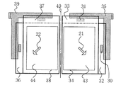
図1に示すように、第1の液晶パネル41と、第1の液晶パネルに接続するフレキシブル基板35と、第2の液晶パネル42と、第2の液晶パネルに接続するフレキシブル基板39とから構成されている。第1の液晶パネル41は上側に信号電極駆動用IC31を備え、第1の液晶パネル41の信号電極(図示せず)に電圧を印加している。第2の液晶パネル42は上側に信号電極駆動用IC31を備え、第2の液晶パネル42の信号電極(図示せず)に電圧を印加している。
【0014】
第1の液晶パネル41の右側に、つまり液晶パネル同士が接続されている一辺に対向する一辺側に、走査電極駆動用IC30を備えており、この走査電極駆動用IC30からの信号を、第1の液晶パネル41の走査電極(図示せず)に印加している。第2の液晶パネル42の左側に、つまり液晶パネル同士が接続されている一辺に対向する一辺側にも、走査電極駆動用IC30を備えており、この走査電極駆動用IC30からの信号を、第2の液晶パネル42の走査電極(図示せず)に印加している。
【0015】
そして、第1の液晶パネル41の優先視野角方向21は3時方向にしてあり、第2の液晶パネル42の優先視野角方向22は9時方向にしてある。つまり、優先視野角方向は開閉軸側にある液晶パネルの一辺側から、対向する一辺側へと向かう方向に設定してあり、ここでは開閉軸方向と直角の方向としている。そして、2の液晶パネルは、開閉軸40を中心に折りたたむことが可能である。2枚の液晶パネルを完全に開かず、V字型にした場合、第1の液晶パネル41は3時方向から見ることになり、つまり、第1の液晶パネル41の優先視野角方向から見ることになり、ほとんど色変化は発生せず、僅かにコントラストが減少する。
【0016】
一方、第2の液晶パネル42は9時方向から見ることになり、つまり、第2の液晶パネル42の優先視野角方向から見ることになり、やはり、ほとんど色変化は発生せず、僅かにコントラストが減少する。そのために、2枚の液晶パネルの表示色やコントラストはほとんど同一であり、連続した表示でも見やすくなる。
【0017】
次に、他の第1の液晶パネルと第2の液晶パネルの構成を図2に示す。図2に示すように、第1の液晶パネル43と、フレキシブル基板35と、第2の液晶パネル44と、フレキシブル基板39とから構成されている。そして、第1の液晶パネル43の優先視野角方向21は4時30分方向にしてあり、第2の液晶パネル44の優先視野角方向22は7時30分方向にしてある。つまり、優先視野角方向は開閉軸にある液晶パネルの一辺側から、対向する一辺側へと向かう方向に設定してあり、ここでは開閉軸方向とのなす角度を45゜となるように設定している。
【0018】
そして、2つの液晶パネルを完全に開かず、V字型にした場合、第1の液晶パネル43は3時方向から見ることになり、つまり、第1の液晶パネル43の優先視野角方向から45゜右に傾けた方向から見ることになり、僅かに色調は茶色に変化する。一方、第2の液晶パネル44は、9時方向から見ることになり、つまり、第2の液晶パネル44の優先視野角方向から45゜左に傾けた方向から見ることになり、僅かに緑色を帯びる。しかし、図4に示した従来例よりは、色変化が少なく、さらに、V字型に開いた2枚の液晶パネルを少し前傾させて見る場合は、どちらの液晶パネルも、ほぼ優先視野角方向から見ることになり、ほとんど色変化がなくなり、連続した表示でも見やすくなる。
【0019】
次に、他の第1の液晶パネルと第2の液晶パネルの構成を図3に示す。2枚の液晶パネルを上下に配置してあり、第1の液晶パネル45を上側に配置し、第2の液晶パネル46を下側に配置し、開閉軸40は水平である。そして、第1の液晶パネル45の優先視野角方向21は12時方向にしてあり、第2の液晶パネル46の優先視野角方向22は6時方向にしてある。つまり、開閉軸にある液晶パネルの一辺側から、対向する一辺側方向に設定してあり、ここでは開閉軸方向と直角の方向としている。
【0020】
そして、2つの液晶パネルを完全に開かず、くの字型にした場合、第1の液晶パネル45は12時方向から見ることになり、第2の液晶パネル46は6時方向から見ることになり、どちらの液晶パネルも優先視野角方向から見ることになり、2枚の液晶パネルの表示色やコントラストはほとんど同一であり、連続した表示でも見やすくなる。
【0021】
図1から図3に示したように、第1の液晶パネルと第2の液晶パネルとの、2枚の液晶パネルを用い、かつ、第1の液晶パネルおよび第2の液晶パネルにおけるそれぞれの優先視野角方向は、開閉軸を対称軸として対称な方向に設けることにより、2枚の液晶パネルを完全に開かず、V時型に開いた状態でも、2枚の液晶パネルの色調やコントラストが同じであり、連続した表示でも見やすい表示が得られ、携帯時は折りたたんで外形を小さくでき、使用時は広げて大画面表示が可能な液晶表示装置を提供することができる。
【0022】
【実施例】
(実施例1:図1,図5,図7)
以下、本発明の液晶表示装置の実施例を用いて、本発明の構成と効果を説明する。まずはじめに、本発明の実施例1における液晶表示装置の構成を、図面を用いて説明する。図1は、本発明の液晶パネルの構成を説明するための模式図で、図5は本発明の実施例1における液晶表示装置の構成要素を説明するための断面図で、図7は本発明の実施例1における液晶表示装置の構成部材の配置関係を示す平面図である。
【0023】
本発明の液晶表示装置は第1の液晶パネルの一辺と第2の液晶パネルの一辺とが近接するように、第1の液晶パネル41と第2の液晶パネル42とが接続されており、かつ接続部を開閉軸40として、第1と第2の液晶パネルが向き合うように開閉できるような機構を有している。
【0024】
それぞれの液晶パネルには通常の一般的な液晶パネルを使用することができる。本実施例では位相差板を用いたSTNモードの反射型の液晶パネルを使用した。図5を用いて、本実施例で使用した、第1の液晶パネルの構成を説明する。液晶素子19と、液晶素子19の外側に設けた位相差板13と上偏光板11と、液晶素子19の下側に設けた下偏光板15と反射板17により構成され、反射型の液晶パネルとなっている。液晶素子19は、透明電極材料であるITOからなる走査電極3が形成されている、厚さ0.5mmのガラス板からなる第1の基板1と、ITOからなる信号電極4が形成されている厚さ0.5mmのガラス板からなる第2の基板2と、第1の基板1と第2の基板2を張り合わせるシール材5と、第1の基板1と第2の基板2に狭持され、左回り240゜ツイスト配向しているネマチック液晶6とから形成している。
【0025】
図5に示した走査電極3は、シール材5の下を通り、液晶パネルの一辺側の接続部32まで引き出され、走査電極駆動用IC30と接続する。図5には示していないが、信号電極4も同様に、液晶パネルの一辺側の接続部33まで引き出され、信号電極駆動IC31と接続する。
【0026】
第2の液晶パネルも、走査電極駆動用ICとの接続部の位置が異なる以外は、第1の液晶パネルと同一構成の液晶パネルを用いることができるので、構成の説明は省略する。
【0027】
第1の液晶パネル41と第2の液晶パネル42の構成を図1に示す。図1に示すように、第1の液晶パネル41と、第1の液晶パネルに接続するフレキシブル基板35と、第2の液晶パネル42と、第2の液晶パネルに接続するフレキシブル基板39とから構成されている。第1の液晶パネル41における上部の接続部33に信号電極駆動用IC31を備え、第1の液晶パネル41の信号電極に電圧を印加している。第1の液晶パネルにおける右側の接続部32には、走査電極駆動用IC30を備え、この走査電極駆動用IC30からの信号を、第1の液晶パネル41の走査電極へ印加している。
【0028】
第2の液晶パネル42も同様に、上部の接続部37に信号電極駆動用IC31と、左側の接続部36に走査電極駆動用IC30を備えている。表示の連続性を改善するために、第1の液晶パネルの有効表示部34と第2の液晶パネルの有効表示部38は、開閉軸40側へ片寄せて設けてある。
【0029】
そして、第1の液晶パネル41の優先視野角方向21は3時方向に設定してあり、第2の液晶パネル42の優先視野角方向22は9時方向にしてある。つまり、開閉軸40を対称軸として、180゜逆方向に2つの液晶パネルの優先視野角方向を設けてある。よって、図1に示すように、第1の液晶パネル41および第2の液晶パネル42におけるそれぞれの優先視野角方向は、開閉軸40側にある第1と第2の液晶パネルの一辺側から、対向する一辺側へと向かう方向であり、かつ第1の液晶パネル43の優先視野角方向21と第2の液晶パネル44の優先視野角方向22とは、開閉軸を対称軸として対称な方向にある。優先方向を第1の液晶パネルと第2の液晶パネルで違う方向にするために、液晶パネルのラビング方向と、構成部材の配置角度が異なっている。この配置関係について図7を用いて説明する。
【0030】
第1の液晶パネル41における各構成部材の配置関係を図7(a)に示す。水平軸Hを基準にし、反時計回りを正の回転方向と定義する。第1の電極3と第2の電極4の表面には配向膜(図示せず)が形成され、図7(a)に示すように、第1の基板1は、水平軸Hに対して、反時計回り120゜方向にラビング処理することで、下液晶分子配向方向6aは+120゜となり、矢印方向にチルト角が発生し、第2の基板2は反時計回り60゜方向にラビング処理することで上液晶分子配向方向6bは+60゜となり、矢印方向にチルト角が発生する。
【0031】
粘度20cpのネマチック液晶には、カイラル材と呼ぶ旋回性物質を添加し、ねじれピッチPを11μmに調整し、液晶パネルに注入することで、左回りで240゜ツイストのSTNモードの液晶素子19を形成する。使用するネマチック液晶6の複屈折差Δnは0.131で、第1の基板1と第2の基板2の隙間であるセルギャップdは6.2μmとする。したがって、ネマチック液晶6の複屈折の差Δnとセルギャップdとの積で、液晶素子19の複屈折量Δnd値は0.81μmとなる。
【0032】
上偏光板11の吸収軸11aは、水平軸Hを基準にして、−72゜に配置する。位相差板13の遅相軸13aは水平軸Hを基準にして−27゜に配置しており、下偏光板15の吸収軸15aは、水平軸Hを基準にして−20゜に配置することで、優先視野角方向21は3時方向となる。よって、開閉軸40方向と優先視野角方向21とのなす角度は90゜となっている。
【0033】
第2の液晶パネル42における各構成部材の配置関係を図7(b)に示す。第1の基板1は、水平軸Hに対して、時計回り60゜にラビング処理することで、下液晶分子配向方向6aは−60゜となり、矢印方向にチルト角が発生し、第2の基板2は時計回り120゜方向にラビング処理することで上液晶分子配向方向6bは−120゜となり、矢印方向にチルト角が発生する。
【0034】
上偏光板11の吸収軸11aは、水平軸Hを基準にして、−72゜に配置し、位相差板13の遅相軸13aは水平軸Hを基準にして−27゜に配置しており、下偏光板15の吸収軸15aは、水平軸Hを基準にして−20゜に配置することで、優先視野角方向22は9時方向となる。よって、開閉軸40方向と優先視野角方向22とのなす角度は90゜となっている。
【0035】
次に、本実施例の効果について説明する。2つの液晶パネルを完全に開かず、開閉軸40を奥側に配置し、手前にV字型に開いた場合、図1から分かるように、第1の液晶パネル41は3時方向から見ることになり、つまり、第1の液晶パネル41の優先視野角方向から見ることになり、ほとんど色変化は発生せず、僅かにコントラストが減少する。
【0036】
一方、第2の液晶パネル42は9時方向から見ることになり、つまり、第2の液晶パネル42の優先視野角方向から見ることになり、やはり、ほとんど色変化は発生せず、僅かにコントラストが減少する。そのために、2枚の液晶パネルの表示色やコントラストはほとんど同一であり、連続した表示でも見やすくなる。
【0037】
また、2枚の液晶パネルを完全に開いた場合でも、第1の液晶パネル41は正面から僅かに9時方向に傾けた方向から見ることになり、優先視野角方法21と逆方向となるが、角度が小さいので、ほとんどコントラストは低下しない。また、第2の液晶パネル42は正面から僅かに3時方向に傾けた方向から見ることになり、優先視野角方法22と逆方向となるが、第1の液晶パネルと同様なコントラストと色調となり、連続した表示でも見やすくなる。
【0038】
そして、携帯時は2枚の液晶パネルの中央にある開閉軸40で折りたたむことで小型化をはかり、使用時は広げることで大画面大容量表示が可能であり、かつ、完全に2枚の液晶パネルを開かず、V字型に開いた時でも見やすい表示が可能な液晶表示装置を提供できる。
【0039】
(実施例2:図2,図6,図8)
次に、本発明における実施例2の液晶表示装置の構成について説明する。実施例2の液晶表示装置は、液晶パネルがTNモードであること、優先視野角方向が4時30分と7時30分であることが、実施例1と異なっている。
【0040】
本発明の実施例2における液晶表示装置の構成を、図面を用いて説明する。図2は本発明の実施例2の構成を説明するための模式図で、図6は本発明の実施例2における液晶表示装置の構成要素を説明するための断面図で、図8は本発明の実施例2における液晶表示装置の構成部材の配置関係を示す平面図である。
【0041】
実施例2の液晶表示装置も、実施例1と同様に、第1の液晶パネル43と第2の液晶パネル44とが接続されており、かつ接続部を開閉軸40として、第1と第2の液晶パネルが向き合うように開閉できるような機構を有している。
【0042】
実施例2では、TNモードの液晶パネルを用いた。図6を用いて、本実施例で使用した、第1の液晶パネルの構成を説明する。液晶素子20と、液晶素子20の外側に設けた上偏光板11と、液晶素子20の下側に設けた下偏光板15と反射板17により構成され、反射型の液晶パネルとなっている。液晶素子20は、透明電極材料であるITOからなる走査電極3が形成されている、厚さ0.5mmのガラス板からなる第1の基板1と、ITOからなる信号電極4が形成されている厚さ0.5mmのガラス板からなる第2の基板2と、第1の基板1と第2の基板2を張り合わせるシール材5と、第1の基板1と第2の基板2に狭持され、左回り90゜ツイスト配向しているネマチック液晶6とから形成している。
【0043】
図6に示した走査電極3は、シール材5の下を通り、液晶パネルの一辺側の接続部32まで引き出され、走査電極駆動用IC30と接続する。図6には示していないが、信号電極4も同様に、液晶パネルの一辺側の接続部33まで引き出され、信号電極駆動IC31と接続する。
【0044】
第2の液晶パネルも、走査電極駆動用ICとの接続部の位置が異なる以外は、第1の液晶パネルと同一構成の液晶パネルを用いることができるので、構成の説明は省略する。表示の連続性を改善するために、第1の液晶パネルの有効表示部34と第2の液晶パネルの有効表示部38は、開閉軸40側へ片寄せて設けてある。
【0045】
そして、第1の液晶パネル43の優先視野角方向21は4時30分方向に設定してあり、第2の液晶パネル44の優先視野角方向22は7時30分方向にしてある。つまり、開閉軸40方向とのなす角度をそれぞれ45゜となるように、優先視野角方向を設けている。よって、図2に示すように、第1の液晶パネル43および第2の液晶パネル44におけるそれぞれの優先視野角方向は、開閉軸40側にある第1と第2の液晶パネルの一辺側から、対向する一辺側へと向かう方向であり、かつ第1の液晶パネル43の優先視野角方向21と第2の液晶パネル44の優先視野角方向22とは、開閉軸を対称軸として対称な方向にある。優先視野角方向を第1の液晶パネルと第2の液晶パネルで違う方向にするために、液晶パネルのラビング方向と、構成部材の配置角度が異なっている。この配置関係について図8を用いて説明する。
【0046】
第1の液晶パネル43における各構成部材の配置関係を図8(a)に示す。水平軸Hを基準にし、反時計回りを正の回転方向と定義する。第1の電極3と第2の電極4の表面には配向膜(図示せず)が形成され、図8(a)に示すように、第1の基板1は、水平軸Hの方向にラビング処理することで、下液晶分子配向方向6aは0゜となり、矢印方向にチルト角が発生し、第2の基板2は反時計回り90゜方向にラビング処理することで上液晶分子配向方向6bは+90゜となり、矢印方向にチルト角が発生する。
【0047】
粘度20cpのネマチック液晶には、カイラル材と呼ぶ旋回性物質を添加し、ねじれピッチPを100μmに調整し、液晶パネルに注入することで、左回りで90゜ツイストのTNモードの液晶素子20を形成する。使用するネマチック液晶6の複屈折差Δnは0.15で、第1の基板1と第2の基板2の隙間であるセルギャップdは7.3μmとする。したがって、ネマチック液晶6の複屈折の差Δnとセルギャップdとの積で、液晶素子20の複屈折量Δnd値は1.1μmとなる。
【0048】
上偏光板11の吸収軸11aは、水平軸Hを基準にして、+90゜に配置し、下偏光板15の吸収軸15aは、水平軸Hを基準にして0゜に配置することで、優先視野角方向21は4時30分方向となる。
【0049】
第2の液晶パネル44における各構成部材の配置関係を図8(b)に示す。第1の基板1は、水平軸Hに対して、時計回り90゜にラビング処理することで、下液晶分子配向方向6aは−90゜となり、矢印方向にチルト角が発生し、第2の基板2は水平軸Hと平行な方向にラビング処理することで上液晶分子配向方向6bは0゜となり、矢印方向にチルト角が発生する。
【0050】
上偏光板11の吸収軸11aは、水平軸Hを基準にして0゜に配置し、下偏光板15の吸収軸15aは、水平軸Hを基準にして90゜に配置することで、優先視野角方向22は7時30分方向となる。
【0051】
次に、本実施例の効果について説明する。実施例2では、TNモードを用いたので、実施例1のSTNモードとは異なり、優先視野角方向から±90゜方向ではコントラストや色調の変化は非常に少ない。2枚の液晶パネルを完全に開かず、開閉軸40を奥側に配置し、手前にV字型に開いた場合、図2から分かるように、第1の液晶パネル43は3時方向から見ることになり、つまり、第1の液晶パネル43の優先視野角方向から反時計回りに45゜方向見ることになり、コントラストはあまり低下しない。
【0052】
一方、第2の液晶パネル44は9時方向から見ることになり、つまり、第2の液晶パネル44の優先視野角方向から時計回りに45゜方向から見ることになり、コントラストはあまり低下せず、そのために、2枚の液晶パネルを用いる連続した表示でも見やすくなる。
【0053】
さらに、V字型に開いた2枚の液晶パネルを少し前傾させて見る場合は、どちらの液晶パネルも、ほぼ優先視野角方向から見ることになり、ほとんど色変化がなくなり、連続した表示でも見やすくなる。
【0054】
また、2枚の液晶パネルを完全に開いた場合でも、第1の液晶パネル43は正面から僅かに9時方向に傾けた方向から見ることになり、優先視野角方法21と逆方向となるが、角度が小さいので、ほとんどコントラストは低下しない。また、第2の液晶パネル44は正面から僅かに3時方向に傾けた方向から見ることになり、優先視野角方法22と逆方向となるが、第1の液晶パネルと同様なコントラストと色調となり、連続した表示でも見やすくなる。
【0055】
そして、携帯時は、2枚の液晶パネルの中央で折りたたむことで小型化をはかり、使用時は広げることで大画面大容量表示が可能であり、かつ、完全に2枚の液晶パネルを開かず、V字型に開いた時でも見やすい表示が可能な液晶表示装置を提供できる。
【0056】
実施例2では、第1の液晶パネル43の優先視野角方向21は4時30分方向に、第2の液晶パネル44の優先視野角方向22は7時30分方向に設定し、優先視野角方向と開閉軸40方向とのなす角度をそれぞれ45゜になるように配置した。例えば、第1の液晶パネルの優先視野角方向21を1時30分、第2の液晶パネルの優先視野角方向22を10時30分として配置しても、また、その間の角度に配置しても、同様な効果が得られる。
【0057】
(実施例3:図3、図5、図9)
次に、本発明における実施例3の液晶表示装置の構成について説明する。実施例3の液晶表示装置は、2枚の液晶パネルを上下に備え、優先視野角方向が12時と6時であることが実施例1と異なっている。
【0058】
本発明の実施例3における液晶表示装置の構成を、図面を用いて説明する。図3は本発明で採用した2枚の液晶パネルにおける構成を説明するための模式図で、図9は本発明の実施例3における液晶表示装置の構成部材の配置関係を示す平面図である。各液晶パネルの断面構造は実施例1で示した図5と同一であるので省略する。
【0059】
実施例3の液晶表示装置は、第1の液晶パネル45を上側に配置し、第2の液晶パネル46を下側に配置してある。そして、実施例1と同様に、第1の液晶パネルと第2の液晶パネルとが接続されており、かつ接続部を水平な開閉軸40として、第1と第2の液晶パネルが、くの字型に開閉できるような機構を有している。フレキシブル基板35は、1枚で両方の液晶パネルに接続し、部品点数を減少してある。
【0060】
実施例3では、実施例1と同じSTNモードの液晶パネルを用いたので、構成の説明は省略する。次に、配置関係について図9を用いて説明する。
【0061】
第1の液晶パネル45における各構成部材の配置関係を図9(a)に示す。水平軸Hを基準にし、反時計回りを正の回転方向と定義する。第1の基板1は、水平軸Hに対して時計回り150゜方向にラビング処理することで、下液晶分子配向方向6aは−150゜となり、矢印方向にチルト角が発生し、第2の基板2は反時計回り150゜方向にラビング処理することで上液晶分子配向方向6bは+150゜となり、矢印方向にチルト角が発生する。
【0062】
粘度20cpのネマチック液晶には、カイラル材と呼ぶ旋回性物質を添加し、ねじれピッチPを11μmに調整し、液晶パネルに注入することで、左回りで240゜ツイストのSTNモードの液晶素子19を形成する。使用するネマチック液晶6の複屈折差Δnは0.131で、第1の基板1と第2の基板2の隙間であるセルギャップdは6.2μmとする。したがって、ネマチック液晶6の複屈折の差Δnとセルギャップdとの積で、液晶素子19の複屈折量Δnd値は0.81μmとなる。
【0063】
上偏光板11の吸収軸11aは、水平軸Hを基準にして、+18゜に配置し、下偏光板15の吸収軸15aは、水平軸Hを基準にして+70゜に配置することで、優先視野角方向21は12時方向となる。
【0064】
第2の液晶パネル46における各構成部材の配置関係を図9(b)に示す。第1の基板1は、水平軸Hに対して、反時計回り30゜にラビング処理することで、下液晶分子配向方向6aは+30゜となり、矢印方向にチルト角が発生し、第2の基板2は水平軸Hに対して時計回り30゜方向にラビング処理することで、上液晶分子配向方向6bは−30゜となり、矢印方向にチルト角が発生する。
【0065】
偏光板と位相差板の配置は、第1の液晶パネル45と全く同一であり、上偏光板11の吸収軸11aは、水平軸Hを基準にして+18゜に配置し、下偏光板15の吸収軸15aは、水平軸Hを基準にして+70゜に配置することで、優先視野角方向22は6時方向となる。
【0066】
よって、図3に示すように、第1の液晶パネル45および第2の液晶パネル46におけるそれぞれの優先視野角方向は、開閉軸40側にある第1と第2の液晶パネルの一辺側から、対向する一辺側へと向かう方向であり、ここではそれぞれの優先視野角方向21、22と開閉軸40方向とのなす角度は90゜と設定した。また第1の液晶パネル45の優先視野角方向21と第2の液晶パネル46の優先視野角方向22とは、開閉軸を対称軸として対称な方向にある。
【0067】
次に、実施例3の効果について説明する。2つの液晶パネルを完全に開かず、開閉軸40を奥側に配置し、くの字型に開いた場合、図3から分かるように、第1の液晶パネル45は12時方向から見ることになり、つまり、第1の液晶パネル45の優先視野角方向から見ることになり、ほとんど色変化は発生せず、僅かにコントラストが減少する。
【0068】
一方、第2の液晶パネル46は6時方向から見ることになり、つまり、第2の液晶パネル46の優先視野角方向から見ることになり、やはり、ほとんど色変化は発生せず、僅かにコントラストが減少する。そのために、2枚の液晶パネルの表示色やコントラストはほとんど同一であり、連続した表示でも見やすくなる。
【0069】
また、2枚の液晶パネルを完全に開いた場合でも、第1の液晶パネル45は正面から僅かに6時方向に傾けた方向から見ることになり、優先視野角方法21と逆方向となるが、角度が小さいので、ほとんどコントラストは低下しない。また、第2の液晶パネル46は正面から僅かに12時方向に傾けた方向から見ることになり、優先視野角方法22と逆方向となるが、第1の液晶パネルと同様なコントラストと色調となり、連続した表示でも見やすくなる。
【0070】
そして、携帯時は、2枚の液晶パネルの中央で、上下に折りたたむことで小型化をはかり、使用時は広げることで大画面大容量表示が可能であり、かつ、完全に2枚の液晶パネルを開かず、くの字型に開いた時でも見やすい表示が可能な液晶表示装置を提供できる。
【0071】
これらの実施例が示すように、使用する液晶パネルの縦と横の長さが極端に異なる、つまりとても細長い液晶パネルを使用する場合を除いて、開閉軸方向と優先視野角方向とのなす角度は45゜付近から90゜とするのが好ましい。また開閉軸を中心に開閉するので、90゜に設定するのが特に好ましい。
【0072】
(各実施例の変形例)
実施例1から実施例3では、駆動用ICを液晶パネルの一辺側の端に直接接続するCOG方式の接続方式を用いたが、駆動用ICをフレキシブル基板に搭載し、フレキシブル基板を液晶パネルの一辺側の端に接続するTAB方式や、COF方式で接続することも、もちろん可能である。
【0073】
また、実施例1から実施例3では、第1または第2の液晶パネルの上部に信号電極駆動用ICを接続し、第1または第2の液晶パネルの右側に走査電極駆動用ICを設けたが、どちらか一方または両方の液晶パネルの上部に走査電極駆動用ICを接続し、第1と第2の液晶パネルの右側、あるいは左側のどちらか一方、あるいは両方に信号電極駆動用ICを接続することも可能である。また、実施例1と実施例2では、液晶パネルの上部に、駆動用ICを設けたが、液晶パネルの下部に設けることももちろん可能である。同様に、実施例3では、液晶パネルの右側に、駆動用ICを設けたが、液晶パネルの左側に設けることももちろん可能である。
【0074】
また、実施例1から実施例3では、白黒液晶表示装置を用いたが、内部にカラーフィルターと反射板を形成した内在反射板型カラー液晶表示装置を用いることも可能であり、高密度で大画面で、かつ、カラー表示が可能な携帯情報機器を実現することが可能となる。
【0075】
また、実施例1と実施例3では、STN液晶用の光学補償素子として、位相差板を1枚用いたが、複数の位相差板や、液晶ポリマーを用いてツイストさせた構造で固定化したねじれ位相差板や、あるいは位相差板とねじれ位相差板の両方を用いても、同様な液晶表示装置を提供できる。
【0076】
【発明の効果】
以上の説明から明らかなように、第1の液晶パネルの優先視野角方向と第2の液晶パネルの優先視野角方向を、開閉軸を対称軸として対称な方向に設けたので、2枚の液晶パネルを完全に開かず、V時型やくの字型に開いた状態でも、2枚の液晶パネルの色調やコントラストが同じであり、連続した表示でも見やすい表示が得られ、携帯時は折りたたんで外形を小さくでき、使用時は広げて大画面表示が可能な液晶表示装置を提供することができる。
【図面の簡単な説明】
【図1】本発明の液晶表示装置の構成を示す模式図である。
【図2】本発明の液晶表示装置の構成を示す模式図である。
【図3】本発明の液晶表示装置の構成を示す模式図である。
【図4】従来の液晶表示装置の構成を示す模式図である。
【図5】本発明の液晶表示装置の構成を示す断面図である。
【図6】本発明の液晶表示装置の構成を示す断面図である。
【図7】本発明の液晶表示装置の配置関係を示す平面図である。
【図8】本発明の液晶表示装置の配置関係を示す平面図である。
【図9】本発明の液晶表示装置の配置関係を示す平面図である。
【符号の説明】
1 第1の基板
2 第2の基板
3 走査電極
4 信号電極
5 シール材
6 ネマチック液晶
11 上偏光板
13 位相差板
15 下偏光板
17 反射板
19 液晶素子(STN)
20 液晶素子(TN)
21 第1の液晶パネルの優先視野角方向
22 第2の液晶パネルの優先視野角方向
32 接続部
35、39 フレキシブル基板
40 開閉軸
41、43、45 第1の液晶パネル
42、44、46 第2の液晶パネル[0001]
BACKGROUND OF THE INVENTION
The present invention relates to a configuration of a liquid crystal display device, and more particularly to a liquid crystal display device using two liquid crystal panels used in a portable information processing device.
[0002]
[Prior art]
With the spread of mobile phones and the spread of personal information devices (PDA devices), a large number of portable information processing devices are on the market. These portable information processing apparatuses are required to be highly functional and color display while being reduced in size and weight. For this reason, there are conflicting demands for liquid crystal display devices, which are smaller and lighter and higher density and larger screen.
[0003]
Conventionally, a liquid crystal display device is composed of a single liquid crystal panel. Therefore, when high-density and large-screen display is performed, the outer shape of the liquid crystal display device inevitably increases, which increases the size of the information processing device and portability. Was getting worse. Therefore, as a liquid crystal display device for a portable information processing apparatus, a small liquid crystal panel must be used, and since the display capacity is small, the screen is switched and displayed many times.
[0004]
[Problems to be solved by the invention]
Therefore, a portable information processing apparatus is proposed in which two liquid crystal panels are used, one liquid crystal panel is provided in the information processing apparatus main body, and the other liquid crystal panel is provided in a lid that opens and closes provided in the information processing apparatus. For example, it is disclosed in JP-A-11-249596 and JP-A-11-167354. In this way, by providing two liquid crystal panels, the lid is closed when not in use, and while being small, the lid is opened at the time of use and the two liquid crystal panels are displayed simultaneously, thereby displaying a large screen. Is possible.
[0005]
Usually, in such a liquid crystal display device including two liquid crystal panels, liquid crystal panels having the same configuration are used, and therefore, the priority viewing angle directions of the liquid crystal panels are the same. A conventional example will be described with reference to FIG. FIG. 4 is a schematic diagram showing the configuration of a conventional liquid crystal display device.
[0006]
The conventional liquid crystal display device includes a first
[0007]
Both the priority
[0008]
Since the viewing angle characteristics of the liquid crystal panel are not symmetrical, the contrast and color tone are different when viewed from the right direction and when viewed from the left direction. In this conventional example, STN (super twisted nematic) liquid crystal is used, so when it is tilted in the 3 o'clock direction, it is brownish, and when it is tilted in the 9 o'clock direction, it is greenish. When the two liquid crystal panels are not completely opened and the opening /
[0009]
The object of the present invention is to solve the above-mentioned problems of the prior art, and the two liquid crystal panels have the same color tone and contrast even when the two liquid crystal panels are not fully opened and are opened in the V-hour type. It is an object to provide a liquid crystal display device that can provide an easy-to-view display even when it is displayed, can be folded when carried and can be reduced in size, and can be expanded when used and can be displayed on a large screen.
[0010]
[Means for Solving the Problems]
The first liquid crystal panel and the second liquid crystal panel are arranged so that one side of the first liquid crystal panel and one side of the second liquid crystal panel are close to each other, and the first liquid crystal panel, the second liquid crystal panel, Open / close shafts for opening and closing so as to face each other, and the priority viewing angle directions in the first liquid crystal panel and the second liquid crystal panel are those of the first and second liquid crystal panels on the open / close shaft side. The direction from one side to the opposite side and the preferred viewing angle direction of the first liquid crystal panel and the preferred viewing angle direction of the second liquid crystal panel are symmetrical with respect to the opening / closing axis. It is characterized by being. The angle formed between the direction of the opening / closing axis and the priority viewing angle direction is set between approximately 45 ° and 90 °. Further, the first liquid crystal panel is arranged on the right side with respect to the opening / closing axis, the second liquid crystal panel is arranged on the left side with respect to the opening / closing axis, and the priority viewing angle direction of the first liquid crystal panel is The dial is set in the 3 o'clock direction, and the priority viewing angle direction of the second liquid crystal panel is set in the 9 o'clock direction. Alternatively, the priority viewing angle direction of the first liquid crystal panel is set in the 4:30 direction on the dial of the watch, and the priority viewing angle direction of the second liquid crystal panel is set in the 7:30 direction. It is characterized by that. Alternatively, the first liquid crystal panel is disposed above the opening / closing axis, the second liquid crystal panel is disposed below the opening / closing axis, and the priority viewing angle direction of the first liquid crystal panel is The dial is set in the 12 o'clock direction, and the priority viewing angle direction of the second liquid crystal panel is set in the 6 o'clock direction.
[0011]
DETAILED DESCRIPTION OF THE INVENTION
Hereinafter, the configuration and operation of a liquid crystal display device in the best mode for carrying out the present invention will be described with reference to the drawings. 1, 2 and 3 are schematic views for explaining the configuration of the liquid crystal display device of the present invention.
[0012]
In the liquid crystal display device of the present invention, the first liquid crystal panel and the second liquid crystal panel are connected so that one side of the first liquid crystal panel and one side of the second liquid crystal panel are close to each other. With this part as an opening / closing axis, it has a mechanism that can be opened and closed so that the first and second liquid crystal panels face each other. Here, the structure of the first liquid crystal panel and the second liquid crystal panel is shown in FIG.
[0013]
As shown in FIG. 1, it comprises a first
[0014]
A scanning
[0015]
The priority
[0016]
On the other hand, the second
[0017]
Next, the configuration of another first liquid crystal panel and a second liquid crystal panel is shown in FIG. As shown in FIG. 2, the first
[0018]
When the two liquid crystal panels are not completely opened and are V-shaped, the first
[0019]
Next, the configuration of another first liquid crystal panel and a second liquid crystal panel is shown in FIG. Two liquid crystal panels are arranged up and down, the first liquid crystal panel 45 is arranged on the upper side, the second
[0020]
If the two liquid crystal panels are not completely opened and are formed in a dogleg shape, the first liquid crystal panel 45 is viewed from the 12 o'clock direction, and the second
[0021]
As shown in FIGS. 1 to 3, two liquid crystal panels, that is, a first liquid crystal panel and a second liquid crystal panel are used, and each priority is given to the first liquid crystal panel and the second liquid crystal panel. The viewing angle direction is set symmetrically with the opening / closing axis as the axis of symmetry, so that the two liquid crystal panels have the same color tone and contrast even when the two liquid crystal panels are opened in a V-shaped manner. Thus, it is possible to provide a liquid crystal display device that can provide easy-to-see display even when continuous display, can be folded when carried and can be reduced in size, and can be widened when used and can be displayed on a large screen.
[0022]
【Example】
(Example 1: FIGS. 1, 5, and 7)
Hereinafter, the configuration and effects of the present invention will be described using embodiments of the liquid crystal display device of the present invention. First, the configuration of the liquid crystal display device according to the first embodiment of the present invention will be described with reference to the drawings. FIG. 1 is a schematic diagram for explaining the configuration of the liquid crystal panel of the present invention, FIG. 5 is a cross-sectional view for explaining the components of the liquid crystal display device in Example 1 of the present invention, and FIG. It is a top view which shows the arrangement | positioning relationship of the structural member of the liquid crystal display device in Example 1 of this.
[0023]
In the liquid crystal display device of the present invention, the first
[0024]
For each liquid crystal panel, an ordinary general liquid crystal panel can be used. In this embodiment, an STN mode reflective liquid crystal panel using a retardation plate was used. The configuration of the first liquid crystal panel used in this embodiment will be described with reference to FIG. A reflection type liquid crystal panel including a liquid crystal element 19, a
[0025]
The
[0026]
Since the second liquid crystal panel can also be a liquid crystal panel having the same configuration as that of the first liquid crystal panel except for the position of the connection portion with the scan electrode driving IC, description of the configuration is omitted.
[0027]
The configuration of the first
[0028]
Similarly, the second
[0029]
The priority
[0030]
FIG. 7A shows the arrangement relationship of the constituent members in the first
[0031]
A nematic liquid crystal having a viscosity of 20 cp is added with a swirling substance called a chiral material, and the twist pitch P is adjusted to 11 μm and injected into the liquid crystal panel, thereby turning the 240 ° twisted STN mode liquid crystal element 19 counterclockwise. Form. The nematic
[0032]
The
[0033]
FIG. 7B shows the arrangement relationship of the constituent members in the second
[0034]
The
[0035]
Next, the effect of the present embodiment will be described. When the two liquid crystal panels are not fully opened and the opening / closing
[0036]
On the other hand, the second
[0037]
Even when the two liquid crystal panels are fully opened, the first
[0038]
And when carrying it, it can be downsized by folding it with the opening and closing
[0039]
(Example 2: FIGS. 2, 6, and 8)
Next, the configuration of the liquid crystal display device according to the second embodiment of the present invention will be described. The liquid crystal display device according to the second embodiment is different from the first embodiment in that the liquid crystal panel is in the TN mode and the priority viewing angle directions are 4:30 and 7:30.
[0040]
The configuration of the liquid crystal display device according to
[0041]
Similarly to the first embodiment, the liquid crystal display device according to the second embodiment is connected to the first
[0042]
In Example 2, a TN mode liquid crystal panel was used. The configuration of the first liquid crystal panel used in this embodiment will be described with reference to FIG. The
[0043]
The
[0044]
Since the second liquid crystal panel can also be a liquid crystal panel having the same configuration as that of the first liquid crystal panel except for the position of the connection portion with the scan electrode driving IC, description of the configuration is omitted. In order to improve display continuity, the
[0045]
The priority
[0046]
FIG. 8A shows the arrangement relationship of the constituent members in the first
[0047]
To a nematic liquid crystal having a viscosity of 20 cp, a swirling substance called a chiral material is added, the twist pitch P is adjusted to 100 μm, and injected into a liquid crystal panel, whereby a 90 ° twisted TN mode
[0048]
The
[0049]
FIG. 8B shows the arrangement relationship of the constituent members in the second
[0050]
The
[0051]
Next, the effect of the present embodiment will be described. In the second embodiment, since the TN mode is used, unlike the STN mode in the first embodiment, changes in contrast and color tone are very small in the ± 90 ° direction from the priority viewing angle direction. When the two liquid crystal panels are not completely opened and the opening / closing
[0052]
On the other hand, the second
[0053]
Furthermore, when viewing two liquid crystal panels opened in a V-shape with a slight forward tilt, both liquid crystal panels will be viewed from almost the preferred viewing angle direction, with almost no color change and continuous display. It becomes easy to see.
[0054]
Further, even when the two liquid crystal panels are fully opened, the first
[0055]
And when carrying it, it can be downsized by folding it at the center of the two LCD panels, and when used, it can be enlarged to display a large screen with a large capacity, and the two LCD panels cannot be opened completely. In addition, a liquid crystal display device capable of displaying easily even when opened in a V shape can be provided.
[0056]
In the second embodiment, the priority
[0057]
(Example 3: FIGS. 3, 5, and 9)
Next, the configuration of the liquid crystal display device according to the third embodiment of the present invention will be described. The liquid crystal display device of the third embodiment is different from the first embodiment in that two liquid crystal panels are provided on the upper and lower sides and the priority viewing angle directions are 12 o'clock and 6 o'clock.
[0058]
A configuration of a liquid crystal display device according to
[0059]
In the liquid crystal display device of Example 3, the first liquid crystal panel 45 is disposed on the upper side, and the second
[0060]
In the third embodiment, the same STN mode liquid crystal panel as that in the first embodiment is used, and thus the description of the configuration is omitted. Next, the arrangement relationship will be described with reference to FIG.
[0061]
FIG. 9A shows the arrangement relationship of the constituent members in the first liquid crystal panel 45. With the horizontal axis H as a reference, the counterclockwise direction is defined as the positive rotation direction. The
[0062]
A nematic liquid crystal having a viscosity of 20 cp is added with a swirling substance called a chiral material, and the twist pitch P is adjusted to 11 μm and injected into the liquid crystal panel, thereby turning the 240 ° twisted STN mode liquid crystal element 19 counterclockwise. Form. The nematic
[0063]
The
[0064]
FIG. 9B shows the arrangement relationship of the constituent members in the second
[0065]
The arrangement of the polarizing plate and the retardation plate is exactly the same as that of the first liquid crystal panel 45, the
[0066]
Therefore, as shown in FIG. 3, the priority viewing angle directions in the first liquid crystal panel 45 and the second
[0067]
Next, the effect of Example 3 will be described. When the two liquid crystal panels are not completely opened and the opening / closing
[0068]
On the other hand, the second
[0069]
Even when the two liquid crystal panels are fully opened, the first liquid crystal panel 45 is viewed from a direction slightly tilted from the front in the 6 o'clock direction, which is opposite to the priority
[0070]
And when you carry it, you can fold it up and down at the center of the two LCD panels to make it smaller, and when you use it, you can enlarge it to display a large screen with a large capacity. It is possible to provide a liquid crystal display device capable of displaying easily even when opened in a square shape without opening.
[0071]
As shown in these examples, the angle formed between the opening / closing axis direction and the preferred viewing angle direction is different except that the vertical and horizontal lengths of the liquid crystal panel to be used are extremely different, that is, a very long liquid crystal panel is used. Is preferably from about 45 ° to 90 °. Moreover, since it opens and closes around an opening-and-closing axis | shaft, setting to 90 degrees is especially preferable.
[0072]
(Modification of each embodiment)
In the first to third embodiments, the COG connection method in which the driving IC is directly connected to the one side end of the liquid crystal panel is used. However, the driving IC is mounted on a flexible substrate, and the flexible substrate is mounted on the liquid crystal panel. Of course, it is also possible to connect by the TAB method connected to the end of one side or the COF method.
[0073]
In the first to third embodiments, the signal electrode driving IC is connected to the top of the first or second liquid crystal panel, and the scanning electrode driving IC is provided on the right side of the first or second liquid crystal panel. However, a scanning electrode driving IC is connected to the upper part of one or both of the liquid crystal panels, and a signal electrode driving IC is connected to one or both of the right and left sides of the first and second liquid crystal panels. It is also possible to do. In the first and second embodiments, the driving IC is provided at the upper part of the liquid crystal panel, but it is of course possible to provide it at the lower part of the liquid crystal panel. Similarly, in
[0074]
In the first to third embodiments, the monochrome liquid crystal display device is used. However, it is also possible to use an internal reflection plate type color liquid crystal display device in which a color filter and a reflection plate are formed. It is possible to realize a portable information device capable of color display with a screen.
[0075]
Further, in Example 1 and Example 3, one retardation plate was used as an optical compensation element for STN liquid crystal. However, the retardation plate was fixed with a plurality of retardation plates or a twisted structure using a liquid crystal polymer. A similar liquid crystal display device can be provided by using a twisted phase difference plate or both a phase difference plate and a twisted phase difference plate.
[0076]
【The invention's effect】
As is clear from the above description, since the priority viewing angle direction of the first liquid crystal panel and the priority viewing angle direction of the second liquid crystal panel are provided in symmetrical directions with the opening / closing axis as the symmetry axis, two liquid crystals Even when the panel is not fully opened and opened in a V-shaped or square shape, the color tone and contrast of the two liquid crystal panels are the same, and it is easy to see even in continuous display. The liquid crystal display device can be provided which can be reduced in size and can be expanded during use to display a large screen.
[Brief description of the drawings]
FIG. 1 is a schematic view showing a configuration of a liquid crystal display device of the present invention.
FIG. 2 is a schematic diagram showing a configuration of a liquid crystal display device of the present invention.
FIG. 3 is a schematic diagram showing a configuration of a liquid crystal display device of the present invention.
FIG. 4 is a schematic diagram showing a configuration of a conventional liquid crystal display device.
FIG. 5 is a cross-sectional view illustrating a configuration of a liquid crystal display device of the present invention.
FIG. 6 is a cross-sectional view illustrating a configuration of a liquid crystal display device of the present invention.
FIG. 7 is a plan view showing the arrangement relationship of the liquid crystal display device of the present invention.
FIG. 8 is a plan view showing the arrangement relationship of the liquid crystal display device of the present invention.
FIG. 9 is a plan view showing the arrangement relationship of the liquid crystal display device of the present invention.
[Explanation of symbols]
1 First substrate
2 Second substrate
3 Scanning electrodes
4 Signal electrodes
5 Sealing material
6 Nematic liquid crystal
11 Upper polarizing plate
13 Phase plate
15 Lower polarizing plate
17 Reflector
19 Liquid crystal element (STN)
20 Liquid crystal element (TN)
21 Preferred viewing angle direction of the first LCD panel
22 Preferred viewing angle direction of the second LCD panel
32 connections
35, 39 Flexible substrate
40 Opening and closing shaft
41, 43, 45 First liquid crystal panel
42, 44, 46 Second liquid crystal panel
Claims (5)
Priority Applications (1)
| Application Number | Priority Date | Filing Date | Title |
|---|---|---|---|
| JP2000135370A JP4522536B2 (en) | 2000-05-09 | 2000-05-09 | Liquid crystal display |
Applications Claiming Priority (1)
| Application Number | Priority Date | Filing Date | Title |
|---|---|---|---|
| JP2000135370A JP4522536B2 (en) | 2000-05-09 | 2000-05-09 | Liquid crystal display |
Publications (3)
| Publication Number | Publication Date |
|---|---|
| JP2001318364A JP2001318364A (en) | 2001-11-16 |
| JP2001318364A5 JP2001318364A5 (en) | 2007-09-27 |
| JP4522536B2 true JP4522536B2 (en) | 2010-08-11 |
Family
ID=18643458
Family Applications (1)
| Application Number | Title | Priority Date | Filing Date |
|---|---|---|---|
| JP2000135370A Expired - Fee Related JP4522536B2 (en) | 2000-05-09 | 2000-05-09 | Liquid crystal display |
Country Status (1)
| Country | Link |
|---|---|
| JP (1) | JP4522536B2 (en) |
Families Citing this family (1)
| Publication number | Priority date | Publication date | Assignee | Title |
|---|---|---|---|---|
| JP2016009112A (en) * | 2014-06-25 | 2016-01-18 | ソニー株式会社 | Display device |
Citations (8)
| Publication number | Priority date | Publication date | Assignee | Title |
|---|---|---|---|---|
| JPH0561423A (en) * | 1991-08-30 | 1993-03-12 | Hiroko Kujirada | Display device |
| JPH0543218U (en) * | 1991-11-11 | 1993-06-11 | 優子 沢田 | Two-screen foldable portable personal computer |
| JPH0571954U (en) * | 1992-03-01 | 1993-09-28 | 光雄 菊地 | Portable electronic devices |
| JPH05298257A (en) * | 1992-04-16 | 1993-11-12 | Toshiba Corp | Portable electronic equipment |
| JPH07181462A (en) * | 1993-12-21 | 1995-07-21 | Hiroshi Ito | Foldable liquid crystal display |
| JPH0854962A (en) * | 1994-08-12 | 1996-02-27 | Hitachi Ltd | Portable personal computer |
| JPH09181802A (en) * | 1995-11-24 | 1997-07-11 | Nokia Mobile Phones Ltd | Composite function mobile communication equipment |
| JPH09247250A (en) * | 1996-03-05 | 1997-09-19 | Sony Corp | Radio device |
-
2000
- 2000-05-09 JP JP2000135370A patent/JP4522536B2/en not_active Expired - Fee Related
Patent Citations (8)
| Publication number | Priority date | Publication date | Assignee | Title |
|---|---|---|---|---|
| JPH0561423A (en) * | 1991-08-30 | 1993-03-12 | Hiroko Kujirada | Display device |
| JPH0543218U (en) * | 1991-11-11 | 1993-06-11 | 優子 沢田 | Two-screen foldable portable personal computer |
| JPH0571954U (en) * | 1992-03-01 | 1993-09-28 | 光雄 菊地 | Portable electronic devices |
| JPH05298257A (en) * | 1992-04-16 | 1993-11-12 | Toshiba Corp | Portable electronic equipment |
| JPH07181462A (en) * | 1993-12-21 | 1995-07-21 | Hiroshi Ito | Foldable liquid crystal display |
| JPH0854962A (en) * | 1994-08-12 | 1996-02-27 | Hitachi Ltd | Portable personal computer |
| JPH09181802A (en) * | 1995-11-24 | 1997-07-11 | Nokia Mobile Phones Ltd | Composite function mobile communication equipment |
| JPH09247250A (en) * | 1996-03-05 | 1997-09-19 | Sony Corp | Radio device |
Also Published As
| Publication number | Publication date |
|---|---|
| JP2001318364A (en) | 2001-11-16 |
Similar Documents
| Publication | Publication Date | Title |
|---|---|---|
| TW574547B (en) | Transflective liquid crystal device and electronic apparatus using the same | |
| CN100478767C (en) | Liquid crystal display device and electronic device | |
| US7528913B2 (en) | Liquid crystal display device which can control viewing angle and electronic device using same | |
| US5946067A (en) | Liquid crystal display | |
| JP3406242B2 (en) | Liquid crystal display | |
| JP4169035B2 (en) | Liquid crystal device and electronic device | |
| TW201025274A (en) | Display device, method for driving the same, and electronic device | |
| US20060146250A1 (en) | Lcd device having adjustable viewing angles | |
| JPH11133408A (en) | Horizontal electric field type liquid crystal display device | |
| US7583346B2 (en) | Multi-domain vertical alignment liquid crystal display | |
| KR101888516B1 (en) | Dual mode liquid crystal display device | |
| US20120133867A1 (en) | Liquid crystal display device | |
| JP2607741B2 (en) | Liquid crystal display | |
| JP2001242831A (en) | Liquid crystal display device | |
| JP4522536B2 (en) | Liquid crystal display | |
| JPH0728065A (en) | Liquid crystal display device | |
| TWI309315B (en) | ||
| JP4095872B2 (en) | Liquid crystal display | |
| JP2002122866A (en) | Color liquid crystal display panel, reflection type color liquid crystal display panel, and semitransmission type color liquid crystal display panel | |
| JP2006330164A (en) | Liquid crystal display device | |
| JP3990754B2 (en) | Reflective monochrome liquid crystal display | |
| US7646459B2 (en) | Liquid crystal display device | |
| JP2004205903A (en) | Liquid crystal display and electronic equipment | |
| JP3324606B2 (en) | Liquid crystal display | |
| JP2009042759A (en) | Liquid crystal display device |
Legal Events
| Date | Code | Title | Description |
|---|---|---|---|
| A621 | Written request for application examination |
Free format text: JAPANESE INTERMEDIATE CODE: A621 Effective date: 20070426 |
|
| RD03 | Notification of appointment of power of attorney |
Free format text: JAPANESE INTERMEDIATE CODE: A7423 Effective date: 20070426 |
|
| A521 | Written amendment |
Free format text: JAPANESE INTERMEDIATE CODE: A523 Effective date: 20070810 |
|
| A977 | Report on retrieval |
Free format text: JAPANESE INTERMEDIATE CODE: A971007 Effective date: 20100330 |
|
| TRDD | Decision of grant or rejection written | ||
| A01 | Written decision to grant a patent or to grant a registration (utility model) |
Free format text: JAPANESE INTERMEDIATE CODE: A01 Effective date: 20100511 |
|
| A01 | Written decision to grant a patent or to grant a registration (utility model) |
Free format text: JAPANESE INTERMEDIATE CODE: A01 |
|
| A61 | First payment of annual fees (during grant procedure) |
Free format text: JAPANESE INTERMEDIATE CODE: A61 Effective date: 20100526 |
|
| R150 | Certificate of patent or registration of utility model |
Ref document number: 4522536 Country of ref document: JP Free format text: JAPANESE INTERMEDIATE CODE: R150 Free format text: JAPANESE INTERMEDIATE CODE: R150 |
|
| FPAY | Renewal fee payment (event date is renewal date of database) |
Free format text: PAYMENT UNTIL: 20130604 Year of fee payment: 3 |
|
| FPAY | Renewal fee payment (event date is renewal date of database) |
Free format text: PAYMENT UNTIL: 20150604 Year of fee payment: 5 |
|
| S533 | Written request for registration of change of name |
Free format text: JAPANESE INTERMEDIATE CODE: R313533 |
|
| R350 | Written notification of registration of transfer |
Free format text: JAPANESE INTERMEDIATE CODE: R350 |
|
| LAPS | Cancellation because of no payment of annual fees |