JP4522346B2 - Color processing method and apparatus - Google Patents
Color processing method and apparatus Download PDFInfo
- Publication number
- JP4522346B2 JP4522346B2 JP2005262985A JP2005262985A JP4522346B2 JP 4522346 B2 JP4522346 B2 JP 4522346B2 JP 2005262985 A JP2005262985 A JP 2005262985A JP 2005262985 A JP2005262985 A JP 2005262985A JP 4522346 B2 JP4522346 B2 JP 4522346B2
- Authority
- JP
- Japan
- Prior art keywords
- conversion
- input
- color
- output
- adjustment
- Prior art date
- Legal status (The legal status is an assumption and is not a legal conclusion. Google has not performed a legal analysis and makes no representation as to the accuracy of the status listed.)
- Expired - Fee Related
Links
Images


Classifications
-
- H—ELECTRICITY
- H04—ELECTRIC COMMUNICATION TECHNIQUE
- H04N—PICTORIAL COMMUNICATION, e.g. TELEVISION
- H04N1/00—Scanning, transmission or reproduction of documents or the like, e.g. facsimile transmission; Details thereof
- H04N1/46—Colour picture communication systems
- H04N1/56—Processing of colour picture signals
- H04N1/60—Colour correction or control
- H04N1/6058—Reduction of colour to a range of reproducible colours, e.g. to ink- reproducible colour gamut
-
- H—ELECTRICITY
- H04—ELECTRIC COMMUNICATION TECHNIQUE
- H04N—PICTORIAL COMMUNICATION, e.g. TELEVISION
- H04N1/00—Scanning, transmission or reproduction of documents or the like, e.g. facsimile transmission; Details thereof
- H04N1/46—Colour picture communication systems
- H04N1/56—Processing of colour picture signals
- H04N1/60—Colour correction or control
- H04N1/603—Colour correction or control controlled by characteristics of the picture signal generator or the picture reproducer
- H04N1/6052—Matching two or more picture signal generators or two or more picture reproducers
-
- H—ELECTRICITY
- H04—ELECTRIC COMMUNICATION TECHNIQUE
- H04N—PICTORIAL COMMUNICATION, e.g. TELEVISION
- H04N1/00—Scanning, transmission or reproduction of documents or the like, e.g. facsimile transmission; Details thereof
- H04N1/46—Colour picture communication systems
- H04N1/56—Processing of colour picture signals
- H04N1/60—Colour correction or control
- H04N1/6083—Colour correction or control controlled by factors external to the apparatus
- H04N1/6088—Colour correction or control controlled by factors external to the apparatus by viewing conditions, i.e. conditions at picture output
Landscapes
- Engineering & Computer Science (AREA)
- Multimedia (AREA)
- Signal Processing (AREA)
- Image Processing (AREA)
- Facsimile Image Signal Circuits (AREA)
- Color Image Communication Systems (AREA)
Description
本発明は、入力デバイスの画像データを出力デバイス用の画像データに変換する色処理に関する。 The present invention relates to color processing for converting image data of an input device into image data for an output device.
図1はカラーマッチングの概念を示す図である。 FIG. 1 is a diagram showing the concept of color matching.
まず、入力プロファイル1によって、入力RGBデータをデバイスに依存しない色空間のXYZデータに変換する。そして、出力プロファイル2によって、XYZデータを出力デバイスに依存する色空間のCMYKデータに変換する。
First, according to the
出力プロファイルを用いた変換には、色域圧縮処理および色域圧縮されたXYZデータをCMYKデータに変換する変換処理が含まれる。出力デバイスは色再現範囲(以下「色域」と呼ぶ)外の色を表現することができない。そこで、色域圧縮処理では、入力色を出力デバイスの色域内にマッピングする。 The conversion using the output profile includes gamut compression processing and conversion processing for converting the XYZ data subjected to the gamut compression into CMYK data. The output device cannot express colors outside the color reproduction range (hereinafter referred to as “color gamut”). Therefore, in the color gamut compression process, the input color is mapped into the color gamut of the output device.
カラーマッチングにおいて基準白色点および環境光は固定されている。例えば、ICC (International Color Consortium)プロファイルは、プロファイルを結び付ける色空間 (PCS: Profile Connection Space)をD50で規定する。このため、入力原稿やプリントをD50特性の光源下で観察する場合は正しい色再現が保証されるが、その他の特性の光源下では正しい色再現は保証されない。 In color matching, the reference white point and the ambient light are fixed. For example, an ICC (International Color Consortium) profile defines a color space (PCS: Profile Connection Space) for connecting profiles with D50. For this reason, when an input document or print is observed under a light source having a D50 characteristic, correct color reproduction is guaranteed, but correct color reproduction is not guaranteed under a light source having other characteristics.
プリンタは、稼動時の気温や湿度などの環境条件、その時点までの経時変化により、色再現特性が変換する。プリンタでは、変化した色再現特性に応じて変換処理条件を較正するキャリブレーションが必要である。 The printer changes color reproduction characteristics depending on environmental conditions such as temperature and humidity during operation and changes with time up to that point. The printer requires calibration for calibrating the conversion processing conditions according to the changed color reproduction characteristics.
同様に、スキャナも、稼動時の気温などの環境条件、その時点までの経時変化により、正確なスキャニングを行う前はキャリブレーションを必要とする。 Similarly, the scanner also needs to be calibrated before performing accurate scanning due to environmental conditions such as temperature during operation and changes over time up to that point.
カラーマッチングの変換条件をデバイスの色再現特性の変化に応じて較正する必要がある。しかし、変換条件の作成は、色再現特性が変動したデバイスの色空間の色信号とデバイスに依存しない色空間の色信号の関係を示すデータを再取得する必要があり、容易ではない。 It is necessary to calibrate the color matching conversion conditions in accordance with changes in the color reproduction characteristics of the device. However, the creation of the conversion condition is not easy because it is necessary to re-acquire data indicating the relationship between the color signal of the device color space in which the color reproduction characteristics fluctuate and the color signal of the color space independent of the device.
本発明は、デバイスの色再現特性の変動を補正する変換テーブルや統合変換テーブルを効率的に生成し、正確な色変換を行うことを目的とする。 It is an object of the present invention to efficiently generate a conversion table and an integrated conversion table for correcting variations in the color reproduction characteristics of a device and perform accurate color conversion .
本発明は、前記の目的を達成する一手段として、以下の構成を備える。 The present invention has the following configuration as one means for achieving the above object.
本発明にかかる色処理は、入力デバイスに依存する色空間の入力データに、デバイスに依存しない色空間のデータに変換する入力変換、出力デバイスの色域のデータに変換する色域変換、前記出力デバイスに依存する色空間のデータに変換する出力変換を含む色変換を施す際に、前記入力または出力デバイスごとに、かつ、変換設定ごとに作成された前記入力変換用の入力変換テーブルおよび前記出力変換用の出力変換テーブル、並びに、前記色域変換用の変換テーブルを統合した統合変換テーブルを使用して、前記入力データに前記色変換を施し、前記入力デバイスの色再現特性の変動を補正する入力変換調整テーブルを作成し、前記入力デバイスに関連する統合変換テーブルがメモリに存在する場合は当該統合変換テーブルと、前記入力変換調整テーブルを合成して、前記統合変換テーブルの前段に前記入力変換調整テーブルを配置した場合の変換特性をもつ統合変換テーブルを生成し、前記入力デバイスに関連する統合変換テーブルが前記メモリに存在しない場合は前記メモリに存在する前記入力デバイスに関連する入力変換テーブルと、前記入力変換調整テーブルを合成して、前記入力変換テーブルの前段に前記入力変換調整テーブルを配置した場合の変換特性をもつ入力変換テーブルを生成し、前記出力デバイスの色再現特性の変動を補正する出力変換調整テーブルを作成し、前記出力デバイスに関連する統合変換テーブルが前記メモリに存在する場合は当該統合変換テーブルと、前記出力変換調整テーブルを合成して、前記統合変換テーブルの後段に前記出力変換調整テーブルを配置した場合の変換特性をもつ統合変換テーブルを生成し、前記出力デバイスに関連する統合変換テーブルが前記メモリに存在しない場合は前記メモリに存在する前記出力デバイスに関連する出力変換テーブルと、前記出力変換調整テーブルを合成して、前記出力変換テーブルの後段に前記出力変換調整テーブルを配置した場合の変換特性をもつ出力変換テーブルを生成することを特徴とする。 Color processing according to the present invention, the input data of a color space dependent on the input device, the input conversion for converting the data of a color space independent of the device, the gamut conversion for converting the data of the color gamut of the output device, the output The input conversion table for input conversion and the output created for each input or output device and for each conversion setting when performing color conversion including output conversion for conversion into device-dependent color space data output conversion table for converting, as well, using the integrated conversion table that integrates a conversion table of the color gamut conversion, and facilities the color conversion to the input data, correct for variations in color reproduction characteristics of the input device and the integrated conversion table if the integrated conversion table creating an input conversion adjustment table, associated with the input device to the presence in the memory, the input A conversion adjustment table is synthesized, and an integrated conversion table having conversion characteristics when the input conversion adjustment table is arranged in the previous stage of the integrated conversion table is generated, and an integrated conversion table related to the input device exists in the memory If not, the input conversion table related to the input device existing in the memory and the input conversion adjustment table are combined, and the conversion characteristics when the input conversion adjustment table is arranged in the previous stage of the input conversion table are provided. Generate an input conversion table, create an output conversion adjustment table that corrects variations in color reproduction characteristics of the output device, and if an integrated conversion table associated with the output device exists in the memory, the integrated conversion table, The output conversion adjustment table is synthesized, and the output conversion adjustment is arranged at the subsequent stage of the integrated conversion table. An integrated conversion table having conversion characteristics when a table is arranged, and an output conversion table related to the output device existing in the memory if the integrated conversion table related to the output device does not exist in the memory; The output conversion adjustment table is synthesized, and an output conversion table having a conversion characteristic when the output conversion adjustment table is arranged at a subsequent stage of the output conversion table is generated .
本発明によれば、デバイスの色再現特性の変動を補正する変換テーブルや統合変換テーブルを効率的に生成し、正確な色変換を行うことができる。 According to the present invention, the conversion table and integrated conversion table for correcting the variation of color reproduction characteristic of a device efficiently produced, Ru can perform accurate color conversion.
以下では、本発明にかかる画像処理を図面を参照して詳細に説明する。 Hereinafter, image processing according to the present invention will be described in detail with reference to the drawings.
●カラーマッチング処理の概念
図2は、以下の実施例におけるカラーマッチング処理の概念を説明する図である。
● Concept of Color Matching Processing FIG. 2 is a diagram for explaining the concept of color matching processing in the following embodiment.
変換マトリクスまたは変換ルックアップテーブル(LUT)を用いた処理を行う変換処理 11は、入力デバイスに依存するデータを入力側の環境光の白色点基準に基づくデバイスに依存しない色空間のデータに変換する。色知覚モデルの順変換部(CAM) 12は、変換LUT 11から得られるデータを色知覚色空間JChまたはQMhへ変換する。JCh(またはJCH)13は、環境光の基準白色に相対的な色知覚空間である。QMh(またはQMH)14は、照度レベルによって大きさが変化する絶対的な色知覚空間である。色知覚モデルの逆変換部(CAM-1) 15は、色知覚空間JChまたはQMhのデータを、出力側の環境光の白色点基準に基づくデバイスに依存しない色空間のデータに変換する。変換マトリクスまたは変換LUTを用いた処理を行う変換処理 16は、逆変換部15から得られるデータを出力デバイスに依存する色空間のデータに変換する。
一般に、観察条件における環境光の白色点は、変換処理条件を作成する際に行う色票の測色における標準光源の白色点とは異なる。例えば、測色の際に使用される標準光源はD50やD65である。しかし、実際に画像を観察する場合の環境光はD50やD65とは限らず、白熱電球や蛍光灯などの照明光や、照明光と太陽光が混合した光である。以下では、簡単化のために、観察条件における環境光の光源特性をD50、D65およびD93とする。なお、メディア上の白色点のXYZ値を白色点として設定しても構わない。 In general, the white point of the ambient light under the observation condition is different from the white point of the standard light source in the colorimetric color measurement performed when the conversion processing condition is created. For example, standard light sources used for colorimetry are D50 and D65. However, the ambient light when actually observing an image is not limited to D50 or D65, but is illumination light such as an incandescent bulb or a fluorescent lamp, or light in which illumination light and sunlight are mixed. Hereinafter, for simplification, the light source characteristics of the ambient light under the observation conditions are set to D50, D65, and D93. Note that the XYZ value of the white point on the medium may be set as the white point.
●カラーマッチング処理の構成
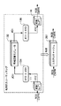
図3はカラーマッチング処理の構成を示す図である。
● Configuration of Color Matching Processing FIG. 3 is a diagram showing the configuration of color matching processing.
変換LUT 11は、データ作成部により観察条件1に基づき作成されるLUTである。LUT 132は、色域圧縮部によりJCH色空間上で作成されるLUTである。LUT 133は、色域圧縮部によりQMH色空間上で作成されるLUTである。変換LUT 16は、データ作成部47により観察条件2に基づき作成されたLUTである。LUT 132、133は、色域圧縮アルゴリズムを備えたマトリクスまたはプログラムに置き換えてもよい。これら色域圧縮を行うモジュールを色域圧縮モジュールと呼ぶ。
The
変換LUT 11は、入力デバイスの色信号であるRGBまたはCMYKの入力色信号を、観察条件1におけるデバイスに依存しない色信号であるXYZ信号へ変換する。色知覚モデル順変換部134、135は、観察条件1(D50光源の白色点、照度レベル、周囲光の状態など)に基づき、XYZ信号を色知覚信号JCHまたはQMHへ変換する。相対的カラーマッチングの場合はJCH空間を、絶対的カラーマッチングの場合はQMH空間をそれぞれ選択する。
The
色域圧縮モジュール132、133は、色知覚信号JCH、QMHを出力デバイスの色域内へ圧縮する。色知覚モデル逆変換部136、137は、色域圧縮された色知覚信号JCHおよびQMHを、観察条件2(D65光源の白色点、照度レベル、周囲光の状態など)に基づき、観察条件2におけるデバイスに依存しない色信号であるXYZ信号へ変換する。そして、変換LUT 134は、XYZ信号を観察条件2における出力デバイスに依存する色信号へ変換する。
The color
以上の処理によって得られたRGBまたはCMYK信号は出力デバイスへ送られて、その色信号によって示される画像がプリントされる。そのプリントアウトを観察条件2の下で観察すれば、観察条件1の下で観察されるオリジナル原稿と、同じ色味に見える。
The RGB or CMYK signal obtained by the above processing is sent to the output device, and an image indicated by the color signal is printed. If the printout is observed under the
●色知覚モデルの処理
図4は入力画像を観察する際の観察条件に応じた補正処理(XYZをJCHまたはQMHに変換する処理)を行う色知覚モデルCIECAM02の順変換における処理内容を説明する図である。
● Color perception model processing Fig. 4 is a diagram for explaining the processing contents in the forward conversion of the color perception model CIECAM02 that performs correction processing (processing to convert XYZ to JCH or QMH) according to the observation conditions when observing the input image It is.
まず、入力画像の観察条件情報として、順応視野の輝度LA (cd/m2)、光源条件における試料の相対三刺激値XYZ、光源条件における白色光の相対三刺激値XwYwZw、光源条件における背景の相対輝度Ybを設定する(S160)。なお、順応視野の輝度LAには、通常、順応視野における白の輝度の20%を選ぶ。また、ステップS180で指定される観察条件のタイプに基づき、入力画像の観察条件情報として、周囲の影響の定数c、色誘導係数Nc、明度コントラスト係数FLL、順応度の係数Fを設定する(S170)。 First, as the observation condition information of the input image, the luminance LA (cd / m 2 ) of the adaptation field, the relative tristimulus value XYZ of the sample under the light source condition, the relative tristimulus value XwYwZw of the white light under the light source condition, and the background of the background under the light source condition The relative luminance Yb is set (S160). The luminance LA of the adaptation field is usually selected to be 20% of the white luminance in the adaptation field. Further, based on the type of viewing condition specified in step S180, the ambient condition constant c, the color induction coefficient Nc, the brightness contrast coefficient FLL, and the adaptation coefficient F are set as the viewing condition information of the input image (S170). ).
ステップS160およびS170で設定した入力画像の観察条件情報に基づき、入力画像を示すXYZに対して以下の処理を行う。 Based on the observation condition information of the input image set in steps S160 and S170, the following processing is performed on XYZ indicating the input image.
まず、人間の生理的な三原色として考えられているBradfordの三原色に基づき、XYZを変換してBradford錐体応答RGBを求める(S100)。人間の視覚は常に観察光源に完全順応するわけではないので、輝度レベルと周囲条件(LAおよびF)に基づき順応度を示す変数Dを求める。そして、変数DおよびXwYwZwに基づき、RGBに対して不完全順応処理を行いRcGcBcに変換する(S110)。 First, Bradford cone response RGB is obtained by converting XYZ based on Bradford's three primary colors considered as human's physiological three primary colors (S100). Since human vision is not always fully adapted to the observation light source, a variable D indicating the degree of adaptation is obtained based on the luminance level and ambient conditions (LA and F). Then, based on the variables D and XwYwZw, incomplete adaptation processing is performed on RGB and converted into RcGcBc (S110).
次に、人間の生理的な三原色として考えられているHunt-Pointer-Estevezの三原色に基づき、RcGcBcを変換してHunt-Pointer-Estevez錐体応答R'G'B'を求める(S120)。このR'G'B'に対して刺激強度レベルによる順応度合いの推定を行い、試料と白の両方に応じた順応後錐体応答R'aG'aB'aを求める(S130)。なお、ステップS130では、順応視野の輝度LAに基づき求まる変数FLを用いて非線型応答圧縮を行う。 Next, RcGcBc is converted based on the three primary colors of Hunt-Pointer-Estevez, which are considered to be human physiological three primary colors, and a Hunt-Pointer-Estevez cone response R′G′B ′ is obtained (S120). The degree of adaptation based on the stimulus intensity level is estimated for this R'G'B ', and a post-adaptation cone response R'aG'aB'a corresponding to both the sample and white is obtained (S130). In step S130, nonlinear response compression is performed using the variable FL obtained based on the luminance LA of the adaptation field of view.
続いて、見えとの相関関係を求めるために、以下の処理を行う。 Subsequently, in order to obtain a correlation with appearance, the following processing is performed.
赤-緑および黄-青の反対色応答abをR'aG'aB'aから求め(S140)、反対色応答abおよび偏心係数から色相Hを求める(S150)。 The red-green and yellow-blue opposite color responses ab are obtained from R'aG'aB'a (S140), and the hue H is obtained from the opposite color response ab and the eccentricity coefficient (S150).
また、Ywおよび背景の相対輝度Ybから背景誘導係数nを求め、背景誘導係数nを用いて試料および白の両方に関する無彩色応答AおよびAwが求める(S190)。そして、背景誘導係数nおよび明度コントラスト係数FLLから求まる係数z、および、A、Aw、cに基づき明度Jを求める(S151)。続いて、色誘導係数Ncから飽和度Sを求め(S153)、飽和度Sおよび明度JからクロマCを求め(S152)、明度Jおよび白の無彩色応答Awから輝度Qを求める(S154)。 Further, the background induction coefficient n is obtained from Yw and the relative luminance Yb of the background, and achromatic responses A and Aw for both the sample and white are obtained using the background induction coefficient n (S190). Then, the lightness J is obtained based on the coefficient z obtained from the background induction coefficient n and the lightness contrast coefficient FLL, and A, Aw, c (S151). Subsequently, the saturation S is obtained from the color induction coefficient Nc (S153), the chroma C is obtained from the saturation S and the lightness J (S152), and the luminance Q is obtained from the lightness J and the white achromatic response Aw (S154).
また、変数FLおよび周囲の影響の定数cからカラフルネスMを求める(S155)。 Further, the colorfulness M is obtained from the variable FL and the constant c of the influence of the surroundings (S155).
●色域圧縮モードの選択および色域圧縮
色域圧縮モードは、ユーザによってユーザインタフェイス経由で選択されるか、ソース側プロファイルのヘッダ内のRendering Intentによって自動的に選択される。プロファイルに基づき自動選択される場合は以下のようになる。
Perceptual JCH色空間上の色域圧縮モード
Relative Colorimetric JCH色空間上の色域圧縮モード
Saturation JCH色空間上の色域圧縮モード
Absolute Colorimetric QMH色空間上の色域圧縮モード
Color Gamut Compression Mode Selection and Color Gamut Compression The color gamut compression mode is selected by the user via the user interface or automatically by the Rendering Intent in the header of the source profile. When automatic selection is performed based on the profile, it is as follows.
Color gamut compression mode on Perceptual JCH color space
Relative Colorimetric Color gamut compression mode on JCH color space
Saturation JCH color space color gamut compression mode
Absolute colorimetric color gamut compression mode on QMH color space
つまり、相対的なカラーマッチングの場合、図2に示すJCH空間13が選択され、絶対的なカラーマッチングの場合はQMH空間14が選択される。 That is, in the case of relative color matching, the JCH space 13 shown in FIG. 2 is selected, and in the case of absolute color matching, the QMH space 14 is selected.
図5はJCH 13またはQMH 14上で色域圧縮を行う処理を示すフローチャートである。 FIG. 5 is a flowchart showing processing for performing color gamut compression on JCH 13 or QMH 14.
色知覚空間上で色域圧縮を行うために、出力プロファイル46からユーザに指定されたプロファイルを読み込む(S81)。 In order to perform color gamut compression on the color perception space, a profile designated by the user is read from the output profile 46 (S81).
一般に、出力デバイス用のICCプロファイルは、色域の内か外かを判定(以下「色域の内外判定」と呼ぶ)するために、XYZ値またはLab値を入力する判定LUT (gamut Tag)を格納する。しかし、そのXYZ値は、測色光源の特性であるD50またはD65基準であるため、環境光に応じた色域の内外判定に直接利用することはできない。従って、色域の内外判定を行うLUT (gamut Tag)を利用する代わりに、プロファイルに格納されたCMYK→XYZ変換を行うための変換LUT(AtoB0 Tagなど)からCMYK→XYZ関係データを取り出し(S82)、それを利用して内外判定を行う。また、出力プロファイルには観察条件2も格納されているので、観察条件2を出力プロファイルから取り出す(S83)。
Generally, an ICC profile for an output device uses a judgment LUT (gamut Tag) to input an XYZ value or Lab value in order to judge whether the color gamut is inside or outside (hereinafter referred to as “gamut inside / outside judgment”). Store. However, since the XYZ values are based on the D50 or D65 standard that is the characteristic of the colorimetric light source, it cannot be directly used for the determination of the inside or outside of the color gamut according to the ambient light. Therefore, instead of using the LUT (gamut Tag) for determining whether the color gamut is inside or outside, CMYK → XYZ relation data is extracted from the conversion LUT (AtoB0 Tag, etc.) for CMYK → XYZ conversion stored in the profile (S82). ), Use it to make inside / outside judgments. Since the
ステップS82で取り出したCMYK→XYZ関係データのXYZ値は、測色光であるD50またはD65基準のデータである。従って、環境光基準のXYZ値に修正する必要がある。そこで、測色光基準のXYZ値を、測色条件であるD50光源の白色点「D50基準の場合」、照度レベル、周囲光の状態などに基づき、色知覚モデルにより色知覚空間JCHへ変換する。さらに、測色条件とは異なる観察条件2の例えばD65光源の白色点、照度レベル、周囲光の状態などに基づき、色知覚モデルを用いて再びXYZ値へ逆変換して、環境光基準のXYZ値を得る(S84)。このようにして、デバイスのCMYK値から環境光基準のXYZ値への関係を求める。続いて、ステップS84で得たCMYK→環境光XYZ関係データに基づき、JCHまたはQMH色空間上における出力デバイスの色域を求める(S85)。
The XYZ value of the CMYK → XYZ relation data extracted in step S82 is D50 or D65 reference data that is colorimetric light. Therefore, it is necessary to correct to the XYZ values of the ambient light reference. Therefore, the XYZ values of the colorimetric light reference are converted into the color perception space JCH by the color perception model based on the white point “in the case of D50 reference” of the D50 light source that is the colorimetry condition, the illuminance level, the ambient light state, and the like. Furthermore, based on the
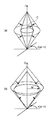
JCHまたはQMH色空間上における出力デバイスの色域は、例えば、下記の八点に対する環境光基準のXYZ値を、ステップS84で求たCMYK→環境光XYZ関係データを用いて計算する。さらに、色知覚モデルにより観察条件2に基づき、色知覚空間JCHまたはQMHの座標値に変換することで、図6に示すような12面体によって近似することができる。
Red (C:0%, M:100%, Y:100%, K:0%)
Yellow (C:0%, M:0%, Y:100%, K:0%)
Green (C:100%, M:0%, Y:100%, K:0%)
Cyan (C:100%, M:0%, Y:0%, K:0%)
Blue (C:100%, M:100%, Y:0%, K:0%)
Magenta(C:0%, M:100%, Y:0%, K:0%)
White (C:0%, M:0%, Y:0%, K:0%)
Black (C:0%, M:0%, Y:0%, K:100%)
The color gamut of the output device on the JCH or QMH color space is calculated, for example, using the CMYK → ambient light XYZ relation data obtained in step S84 for the following eight points of the ambient light reference. Furthermore, by converting the color perception model into the coordinate value of the color perception space JCH or QMH based on the
Red (C: 0%, M: 100%, Y: 100%, K: 0%)
Yellow (C: 0%, M: 0%, Y: 100%, K: 0%)
Green (C: 100%, M: 0%, Y: 100%, K: 0%)
Cyan (C: 100%, M: 0%, Y: 0%, K: 0%)
Blue (C: 100%, M: 100%, Y: 0%, K: 0%)
Magenta (C: 0%, M: 100%, Y: 0%, K: 0%)
White (C: 0%, M: 0%, Y: 0%, K: 0%)
Black (C: 0%, M: 0%, Y: 0%, K: 100%)
12面体で近似した色域において、色域の内部の点、例えば無彩色軸上のWhiteとBlackの中間点と、内外判定対象の入力色信号の点(JCH値またはQMH値)が、同じ側にあれば色域内にあると判定する。また、反対側にあれば色域外にあると判定する。そして、ステップS85の内外判定の結果に基づき色域圧縮を行う(S86)。 In a color gamut approximated by a dodecahedron, a point inside the color gamut, for example, an intermediate point between White and Black on the achromatic color axis, and a point (JCH value or QMH value) of the input color signal to be judged inside / outside are the same side If it is, it is determined that it is in the color gamut. If it is on the opposite side, it is determined that it is out of the color gamut. Then, color gamut compression is performed based on the result of the inside / outside determination in step S85 (S86).
図7はJCH色知覚空間における色域圧縮の概念を、図8はQMH色知覚空間における色域圧縮の概念をそれぞれ示す図である。 FIG. 7 is a diagram showing the concept of color gamut compression in the JCH color perception space, and FIG. 8 is a diagram showing the concept of color gamut compression in the QMH color perception space.
上記の内外判定により、出力デバイスの色域外と判定した入力色信号は、JCH色知覚空間やQMH色知覚空間において、色相角h(またはH)を保存するように、色域内へマッピングする。そして、このマッピングの結果を、相対的カラーマッチングの場合はJCH色知覚空間を入出力色空間とするLUTへ、絶対的カラーマッチングの場合はQMH色知覚空間を入出力色空間とするLUTへ格納する。あるいは、色域圧縮用のマッピングを行う変換マトリクスまたはアルゴリズムを備えるプログラムモジュールに組み込む。 The input color signal determined to be out of the color gamut of the output device by the above internal / external determination is mapped into the color gamut so as to preserve the hue angle h (or H) in the JCH color perception space or QMH color perception space. The result of this mapping is stored in the LUT with the JCH color perception space as the input / output color space for relative color matching, and in the LUT with the QMH color perception space as the input / output color space for absolute color matching. To do. Alternatively, it is incorporated in a program module having a conversion matrix or algorithm for performing mapping for color gamut compression.
図9は異なるデバイス間における色域圧縮の概念を示す図で、破線は入力デバイスの色域を、実線は出力デバイスの色域をそれぞれ示す。 FIG. 9 is a diagram illustrating the concept of color gamut compression between different devices. A broken line indicates the color gamut of the input device, and a solid line indicates the color gamut of the output device.
JCH色知覚空間において、J (lightness)の大きさは、観察条件1および2の光源白色点(以下では「白色点1」「白色点2」と略す場合がある)によってそれぞれ正規化される。従って、Jは環境条件1および2の照度レベル(以下では「照度レベル1」「照度レベル2」と略す場合がある)に依存しない。一方、QMH色知覚空間においては、Q (brightness)の大きさが照度レベル1および2によって変化する。
In the JCH color perception space, the magnitude of J (lightness) is normalized by the light source white point under
つまり、JCH色知覚空間を利用する相対的カラーマッチングにおいて、白色点1はそのまま白色点2になる。一方、QMH色知覚空間を利用する絶対的カラーマッチングでは、照度レベル1>照度レベル2の場合は白色点1が白色点2ヘマッピングされ、照度レベル1<照度レベル2の場合は白色点1が白色点2より低いのでグレーとして出力される。
That is, in the relative color matching using the JCH color perception space, the
●変換LUTの作成およびキャッシュ
図10は出力デバイスの変換LUT 16を作成する手順を説明する図である。
Creation of Conversion LUT and Caching FIG. 10 is a diagram for explaining the procedure for creating the
まず、例えばLab色空間を均等に分割した格子点のLab値に対応する、RGBやCMYKなどの入力値104をデバイス105(モニタおよびCMYKプリンタ)に入力する。そして、デバイス105が出力する色を測色機101で測色して、入力したLab値に対するデバイスの測色値(Lab値)106を取得する。こうして入力Lab値と出力Lab値の対応関係、つまりデバイス105の色再現特性を示すデータを得る。デバイス特性値計算部102は、この対応関係に基づき、デバイスごとの色変換用のデータ、モニタの例えばガンマ値、CMYKプリンタの例えばLUTを計算する。こうして得た色変換用のデータをメモリに保存するが、以下では、デバイスごとに作成され、メモリに保存された色変換用データを「デバイスキャッシュ」103と呼ぶ。デバイスキャッシュ103を作成したデバイス105の色変換を行う場合、再び図10に示す処理を行う必要はない。
First, for example, corresponds to the Lab values of equally divided lattice points Lab color space, and inputs an input value of 1 04, such as a RGB or CMYK to the device 105 (monitor and CMYK printer). Then, the color output by the
例えば、スキャナやデジタルカメラなどの入力デバイスの変換LUT 11もデバイスの色再現特性を示すデータと測色データとの対応関係から求めることができる。
For example, the
以下の実施例では、デバイスキャッシュには、例えば、スキャナやディジタルカメラなどの入力機器の色変換用データも含むものとする。 In the following embodiment, the device cache includes data for color conversion of an input device such as a scanner or a digital camera.
また、デバイスの測色値から色変換用データを作成する方法は、図10に示される方法に限らず、公知の他の方法を適用しても構わない。 Further, the method for creating the color conversion data from the colorimetric values of the device is not limited to the method shown in FIG. 10, and other known methods may be applied.
上述したように、変換LUTを作成する処理は複雑である。従って、デバイスキャッシュを利用することにより、カラーマッチングの処理効率を高めることができる。 As described above, the process of creating the conversion LUT is complicated. Therefore, color matching processing efficiency can be increased by using the device cache.
図11はデバイスキャシュの管理方法を示す図である。 FIG. 11 is a diagram illustrating a device cache management method.
図11はデバイスごとに、デバイスに依存しない色空間とデバイスに依存する色空間を相互に変換する複数の変換LUTのキャッシュ251、252、253、および、各キャッシュのキャッシュ情報256、257、258の対を格納する様子を示している。キャッシュ情報256、257、258には、キャッシュの生成日時、観察条件などの生成条件などを記録する。
FIG. 11 shows, for each device, a plurality of
色知覚モデルに基づく順変換12および逆変換15の処理も複雑である。順変換12および逆変換15の処理も観察条件に対応した処理である。よって、観察条件に対応させて変換LUTをキャッシュすることにより、カラーマッチング処理効率を高めることができる。
Processing of the
以後、カラーマッチング処理に係る各処理に対応するキャッシュを「部分キャッシュ」と呼ぶ。 Hereinafter, a cache corresponding to each process related to the color matching process is referred to as a “partial cache”.
●システムキャッシュ
図3に示すように、相対的カラーマッチング処理では、入力信号を、変換LUT 11によりXYZ信号に変換し、順変換部134によりJCH色空間信号に変換する。さらに、色域圧縮モジュール132により出力デバイスの色域に圧縮し、逆変換部136によりXYZ信号に変換する。そして、変換LUT 16により出力デバイスの色空間の信号に変換する。
System Cache As shown in FIG. 3, in the relative color matching process, the input signal is converted into an XYZ signal by the
カラーマッチングを行う度に、複数の変換および圧縮処理を順次行うと時間がかかる。そこで、例えば入出力デバイスと、観察条件などの条件が定まっているカラーマッチングを行う場合は、一連の処理を合成した変換LUTをキャッシュすることにより、処理の高速化を図る。 It takes time to sequentially perform a plurality of conversion and compression processes each time color matching is performed. Therefore, for example, when performing color matching with input / output devices and conditions such as viewing conditions, the conversion LUT obtained by synthesizing a series of processes is cached to speed up the process.
図12は、図3に示す相対的カラーマッチングを、一つの変換LUTとしてキャッシュ261に合成した様子を示す概念図である。このキャッシュ261を、以下では「システムキャッシュ」と呼ぶことにする。システムキャッシュ261は、入力および出力の変換条件および入力および出力の観察条件および色域圧縮条件に対応させて管理される。
FIG. 12 is a conceptual diagram illustrating a state in which the relative color matching illustrated in FIG. 3 is combined into the
[機能構成]
図13は実施例1にかかる画像処理装置の機能構成例を示すブロック図である。この機能構成は、図5に示すCPU 100がプログラムを実行することにより実現される。
[Function configuration]
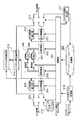
FIG. 13 is a block diagram of a functional configuration example of the image processing apparatus according to the first embodiment. This functional configuration is realized by the
図13に示す機能構成は、大別すると、入力変換部204、順変換部206、逆変換部210、色域圧縮部207、出力変換部211に分けられる。入力画像は、これら部位を通過して出力画像に変換される。
The functional configuration shown in FIG. 13 is roughly divided into an
入力変換部204および出力変換部211は、カラーサンプル216と呼ぶ代表的な幾つかの色の色信号値と測色値の対応関係を格納する情報を使用して、入力画像を変換する。ここで、変換速度を向上するために、変換モデルに与えるパラメータや変換前後の値から生成した個別の変換特性データであるLUT(キャッシュデータ)を記憶部202にデバイスキャッシュとして格納する。
The
また、更なる変換速度の向上のために、入力変換部204、出力変換部211、順変換部206、逆変換部210、色域圧縮部207の全体の入出力を統合した変換特性データであるLUTを記憶部202にシステムキャッシュとして格納する。システム特性適用部214は、このシステムキャッシュを読み出して色変換を実行する。
Further, in order to further improve the conversion speed, it is conversion characteristic data that integrates the entire input / output of the
一般にプリンタのような出力デバイスは、温度、湿度などの変化により色味が変動するためデバイスキャッシュは定期的に更新する必要がある。また、システムキャッシュは、入出力デバイスや色域圧縮方法など、カラーマッチングワークフローの構成要素が変更される度に作り直す必要がある。しかし、デバイスキャッシュやシステムキャッシュの更新の度に、一からキャッシュデータを生成するのは、更新が不要の部位も再計算する必要があり、非効率であり、変換処理時間を長くする。そこで、既存のキャッシュデータを修正する。つまり、入力変換部204、出力変換部211に対応するデバイスキャシュの修正は、入力変換修正部205、出力変換修正部212で行う。また、システム特性適用部214に対応するシステムキャッシュの修正は、システム特性修正部215で行う。
In general, since the color of an output device such as a printer fluctuates due to changes in temperature, humidity, etc., the device cache needs to be updated periodically. In addition, the system cache needs to be recreated every time a component of the color matching workflow such as an input / output device or a color gamut compression method is changed. However, every time the device cache or the system cache is updated, the cache data is generated from the beginning because it is necessary to recalculate the parts that do not need to be updated, which is inefficient and increases the conversion processing time. Therefore, the existing cache data is corrected. That is, the device cache corresponding to the
[キャッシュデータの作成および修正]
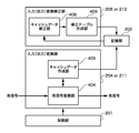
図14は入力変換部204、出力変換部211、入力変換修正部205、出力変換修正部212と記憶部202の関係を示す図である。
[Creating and modifying cache data]
FIG. 14 is a diagram illustrating a relationship between the
入力変換部204は、入力したデバイスに依存する色信号を、色信号変換部404により、デバイスに依存しない色信号に変換して出力する。また、出力変換部211は、入力したデバイスに依存しない色信号を、色信号変換部404により、デバイスに依存する色信号に変換して出力する。色信号変換部404は、制御部201によってカラーサンプル216が入力されると、キャッシュデータ作成部405へ変換パラメータまたは変換テーブル情報を渡す。キャッシュデータ作成部405は、受け取った情報を基に、個別の変換特性データであるキャッシュデータを作成し、記憶部202に保存(デバイスキャッシュ)する。以降、色信号変換部404は、通常の変換を行うか、記憶部202からデバイスキャッシュを読み出して変換を行う。
The
実施例の画像処理装置において、入力画像に対する出力画像の色味を変更するには、入力変換部204、出力変換部211、順変換部206、逆変換部210、色域圧縮部207のモジュールやキャッシュデータを差し替える。これらの方法は、色味を変更することはできるが、局所的な色味を調整するには不充分である。そこで、入力変換修正部205、出力変換修正部212やシステム特性修正部215において色味の修正を行う。
In the image processing apparatus of the embodiment, in order to change the color of the output image with respect to the input image, modules of the
入力変換修正部205、出力変換修正部212は、キャッシュデータ修正部408により、記憶部202から読み出したデバイスキャッシュのキャッシュデータを修正する。そして、修正テーブル作成部409により、修正結果から修正テーブル(キャッシュデータ)を作成して、記憶部202に保存(デバイスキャッシュ)する。
The input
システム特性適用部214も同様である。制御部201は、カラーマッチングワークフローの変換パラメータまたは変換テーブル情報をシステム特性作成部217へ渡す。システム特性作成部217は、受け取った情報を基に、統合した変換特性データであるキャッシュデータを作成し、記憶部202に保存(システムキャッシュ)する。以降、システム特性適用部214は、記憶部202からシステムキャッシュを読み出して変換を行う。また、システム特性修正部215は、記憶部202から読み出したシステムキャッシュのキャッシュデータを修正し、修正結果から修正テーブル(キャッシュデータ)を作成して、記憶部202に保存(システムキャッシュ)する。
The system
なお、インストール制御部208は、後述するプラグインやプロファイルを記憶部202に格納し、記憶部202に格納された、デバイスキャッシュやシステムキャッシュを管理するための制御テーブルを更新する。
Note that the
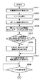
図15および図16は、個別および統合した変換特性データであるキャッシュデータの修正処理を示すフローチャートで、制御部201が実行する処理である。
FIG. 15 and FIG. 16 are flowcharts showing correction processing of cache data that is individual and integrated conversion characteristic data, and are processing executed by the
まず、キャッシュデータ修正部408、および、システム特性修正部217のモジュールを呼び出すと、図17に示す色編集用のユーザインタフェイス(UI)1101をモニタ108に表示する(S201)。ユーザがUIのファイルを開く(File Open)ボタン1109を押すと、修正モジュールに渡すパラメータとして各種データを読み込むために、図18に示すダイアログを表示して、ユーザが指示するファイルを開く(S202)。開くファイルは、入力測色情報(Source MOP)、出力測色情報(Destination MOP)、色空間圧縮モジュール(Gamut Mapping Model)、入力画像(Image)などである。
First, the cache
次に、UI 1101に、入力画像1102を表示し(S203)、開いたファイルの情報を記述したテーブル1103を表示する(S204)。入力ファイルのうち、入出力測色情報には、キャッシュ情報やキャッシュ修正情報を示す情報が記述される場合があり、それらの情報もテーブル1103に表示する。
Next, the
次に、システム特性適用部214に対応するシステムキャッシュが存在するか否かを判定し(S205)、存在すれば、その情報をテーブル1103のシステムキャッシュ (System Cache)行に表示する(S206)。 Next, it is determined whether or not there is a system cache corresponding to the system characteristic application unit 214 (S205). If there is, the information is displayed in the system cache line of the table 1103 (S206).
このようにして設定されたカラーマッチングワークフローに従い、入力画像1102を色変換した変換画像を編集画像として入力画像1102に並べてUI 1101に表示し(S207)、ユーザの指示を待つ待機状態に遷移する(S208)。
In accordance with the color matching workflow set in this way, the converted image obtained by color-converting the
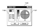
ユーザがUI 1101の色指定ボタン (Range Select) 1110を押すと、図17に示すスポイトアイコン1105を表示するとともに、図19に示す色範囲設定用のダイアログ1104を表示し、ユーザによる色範囲の指定を受け付ける(S301)。スポイトアイコン1105によって指定される入力画像の色と、スポイトアイコン1105が指示する入力画像の座標と同位置にある出力画像の色の情報を計算して、ダイアログ1104のウィンドウ1106に表示する(S302)。なお、図19には、ΔE色差、ΔL(明度差)、ΔC(彩度差)、Δh(色相差)を表示する例を示したが、その他の情報を表示しても構わない。また、ユーザが図27に示す「OK」ボタンを押すと色範囲の指定の受け付けを終了し、色範囲を設定する。
When the user presses the color selection button (Range Select) 1110 on the
次に、修正する色変換のユーザ選択を受け付ける(S303)。ユーザは、修正対象が表示されたテーブル1103の行を選択すること、修正する色変換を指示する。このユーザ選択に対して、選択された色変換のデバイスキャッシュが存在するか否かを判定する(S304)。そして、存在する場合はデバイスキャッシュのキャッシュデータを修正対象にし(S305)、存在しない場合はキャッシュデータを新規に作成し修正対象にする(S306)。 Next, the user selection of the color conversion to be corrected is accepted (S303). The user selects a row of the table 1103 on which the correction target is displayed and instructs color conversion to be corrected. In response to this user selection, it is determined whether or not a device cache for the selected color conversion exists (S304). If it exists, the cache data of the device cache is set as a correction target (S305). If it does not exist, new cache data is created and set as the correction target (S306).
次に、ユーザがUI 1101の修正 (Edit)ボタン1111を押すと、図20に示す色修正用のダイアログ1108を表示し、LChそれぞれの修正量を受け付ける(S307)。図20には、色修正を指定するUIとして、一般的なLChエディタを示すが、これは他の方法を用いても構わない。
Next, when the user presses a correction (Edit)
ユーザが図20に示すLChエディタを操作して、修正量を指定し「OK」ボタンを押すと、その修正量に応じて、指定された色範囲の色を修正したキャッシュデータを作成する(S308)。修正結果のキャッシュデータは記憶部202に保存する際、既に対応するデバイスキャッシュが存在するか否かを判定し(S309)、存在しない場合は当該キャッシュデータに関連情報を記述して記憶部202に保存(デバイスキャッシュ)する(S311)。また、存在する場合は、既存のデバイスキャッシュの更新か、既存のデバイスキャッシュのキャッシュデータと修正結果のキャッシュデータの連結または合成などを行う。そして、修正結果のキャッシュデータに関連情報を記述して記憶部202に保存(デバイスキャッシュ)する(S310)。なお、修正結果のキャッシュデータを記憶部202に保存(デバイスキャッシュ)する際、デバイスキャッシュとデバイス情報を関連付ける、上述した制御テーブルを更新する。
When the user operates the LCh editor shown in FIG. 20 to specify the correction amount and presses the “OK” button, cache data in which the color in the specified color range is corrected according to the correction amount is created (S308). ). When the cache data of the correction result is stored in the
[変換LUTの更新]
図21は変換LUTとプリンタAの色再現の関係を説明する図である。なお、変換LUTは、図3に示す出力側の変換LUT 16に相当する。
[Update conversion LUT]
FIG. 21 is a diagram for explaining the relationship between the conversion LUT and the color reproduction of the printer A. The conversion LUT corresponds to the
図21(a)は、プリンタA用の変換LUT 271aが作成された初期状態を示し、変換LUT 271aは理想的に調整されている。従って、変換LUT 271aが出力する色信号によって得られるプリントアウト272aは、変換LUT 271aに入力するXYZ信号に対して正しい色再現になる。
FIG. 21A shows an initial state in which the
図21(b)は、プリンタAの環境条件(湿度や気温)が変動する、または、プリンタAがプリントを繰り返して経時変化した状態を示し、プリントアウト272bは、XYZ信号に対して不正確な色再現になる。
Fig. 21 (b) shows the state in which the environmental conditions (humidity and temperature) of printer A fluctuate or the printer A has changed over time due to repeated printing. The
図21(b)の特性が変動したプリンタAの状態で、正しい色再現を得るには、出力側の観察条件に対応する変換LUTを再作成することになる。しかし、変換LUTの再作成には、図29(b)の状態におけるプリンタAのCMYK→XYZ関係データを再取得する必要がある。さらに、プリンタAに関するすべての変換LUTは、プリンタAの特性が変動する度に、CMYK→XYZ関係データを取得して、図21(c)に示すように、変換LUT 271cに更新する必要がある。
In order to obtain correct color reproduction in the state of the printer A in which the characteristics shown in FIG. 21B have fluctuated, a conversion LUT corresponding to the observation condition on the output side is recreated. However, in order to recreate the conversion LUT, it is necessary to reacquire the CMYK → XYZ relation data of the printer A in the state shown in FIG. Furthermore, every conversion LUT related to printer A needs to acquire CMYK → XYZ relation data and update to
図22は、初期状態の変換LUTを更新せずに、プリンタAの特性の変動に対応する方法を説明する図である。 FIG. 22 is a diagram illustrating a method for dealing with a change in the characteristics of the printer A without updating the conversion LUT in the initial state.
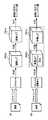
図22(a)に示すように、初期状態の変換LUT271aの後段に、CMYK信号をCMYK信号に変換する調整LUT273aを追加する。初期状態の調整LUT273aは、入力信号をそのまま出力信号にする、実際には変換を行わないLUTである。そして、プリンタAの特性が変動すると、図22(b)に示すように、調整LUT273aを更新して調整LUT273bにして、入力CMYK信号をC'M'Y'K'信号に変換する。つまり、変換LUT271aと調整LUT273bを統合した変換特性は、図21(c)の再作成された変換LUT271cと同じになる。
As shown in FIG. 22 (a), an
調整LUTの更新は、例えばカラーサンプル216をプリンタAで印刷し、カラーサンプルを読み取る。そして、カラーサンプル216の色が正しく再現されるように、CMYK信号をC'M'Y'K'信号に色補正する調整LUTを構成すればよい。そして、図16に示した処理と同様に、調整LUT 273bを記憶部202に保存する際に、対応する変換LUT 271aは既存であるから、変換LUT 271aのキャッシュデータと調整LUT 273bのデータを統合して、記憶部202に保存(デバイスキャッシュ)する(S310)。勿論、プリンタAに対するデバイスキャッシュはすべて、既存の変換LUTと調整LUTを統合した変換特性データに更新する。
For updating the adjustment LUT, for example, the
このように、図21(c)に示す変換LUT 271cと同等のLUTを、変換LUT 271aと調整LUT 273bの組み合わせとして設定することができる。従って、プリンタAの初期状態のCMYK→XYZ関係データに基づき作成した変換LUT 271aを更新することなく、プリンタAの変動に応じた色変換および色補正を行うことできる。
In this way, an LUT equivalent to the
以下、実施例2の画像処理を説明する。なお、実施例2において、上記と略同様の構成については、同一符号を付して、その詳細説明を省略する。 Hereinafter, image processing according to the second embodiment will be described. Note that the same reference numerals in the second embodiment denote the same components as those described above, and a detailed description thereof will be omitted.
図23は、同一の印刷データまたは同一の印刷ジョブを、機種が異なる複数のプリンタを使用して、同一の観察条件における同じ色再現を得るプリンティングシステムの模式図である。 FIG. 23 is a schematic diagram of a printing system that uses the same print data or the same print job to obtain the same color reproduction under the same viewing conditions using a plurality of printers of different models.
図23(a)において、変換LUT 281a、282aが入力するXYZデータは同一であるが、プリンタAとプリンタBは機種が異なるため変換LUT 281a、282aは異なる変換特性をもち、それら変換LUTが出力する色信号はCMYKとC'M'Y'K'の異なる値をもつ。
In FIG. 23 (a), the XYZ data input by the
このプリンティングシステムにおいて、グレイの色味を変更したい場合、図23(b)に示すように、変換LUT 281a、282aをグレイ補正した変換LUT 281b、282bに更新する。これにより、プリンタA、Bによりグレイの色味を同様に変更したプリントアウトを得ることができる。しかし、機種が異なる複数のプリンタ間で同一の色再現を得るには、プリンタごとに、変換LUTを調整する必要がある。
In this printing system, when it is desired to change the color of gray, the
図24は、初期状態の変換LUTを更新せずに、グレイ補正する方法を説明する図である。 FIG. 24 is a diagram for explaining a gray correction method without updating the initial conversion LUT.
図24(a)に示すように、初期状態の変換LUT 281a、282aの前段に、XYZ信号をXYZ信号に変換する調整LUT 283a、284aを追加する。初期状態の調整LUT 283a、284aは、入力信号をそのまま出力信号にする、実際には変換を行わないLUT である。そして、グレイ補正する場合は、図24(b)に示すように、調整LUTを更新して調整LUT 283b、284bにして、入力XYZ信号をX'Y'Z'信号に変換する。つまり、調整LUT 283bと変換LUT 281aを統合した変換特性は、図23(b)の更新された変換LUT 281bと同じになる。また、調整LUT 284bと変換LUT 282aを統合した変換特性は、図23(b)の更新された変換LUT 282bと同じになる。
As shown in FIG. 24 (a),
ところで、調整LUTが入力するXYZ信号は、デバイスに依存しない色空間の色信号である。つまり、調整LUT 283bと284bの変換特性は同一であり、調整LUT 283bと284bに分ける必要はない。従って、図25に示すように、調整LUTは一つにして(調整LUT 285b)、その出力を変換LUT 281a、282aに入力すればよい。
Incidentally, the XYZ signal input by the adjustment LUT is a color signal in a color space that does not depend on the device. That is, the conversion characteristics of the
調整LUTの更新方法は、実施例1のキャッシュデータの作成および修正、並びに、調整LUT の保存と同様であるから、その説明を省略する。 The method of updating the adjustment LUT is the same as the creation and correction of the cache data and the storage of the adjustment LUT according to the first embodiment, and thus the description thereof is omitted.
上記では、二種類のプリンタを想定したが、三種類以上のプリンタを使用するクラスタプリンティングシステムにおいても、上記の調整LUTを適用することができる。 In the above description, two types of printers are assumed. However, the adjustment LUT described above can also be applied to a cluster printing system that uses three or more types of printers.
以下、本発明にかかる実施例3の画像処理を説明する。なお、実施例3において、上記と略同様の構成については、同一符号を付して、その詳細説明を省略する。 Hereinafter, image processing according to the third embodiment of the present invention will be described. Note that the same reference numerals in the third embodiment denote the same components as those described above, and a detailed description thereof will be omitted.
図26は変換LUTとスキャナAの色再現の関係を説明する図である。なお、変換LUTは、図3に示す入力側の変換LUT 11に相当する。
FIG. 26 is a diagram for explaining the relationship between the color reproduction of the conversion LUT and the scanner A. The conversion LUT corresponds to the input-
図26(a)は、スキャナA用の変換LUT 291aが作成された初期状態を示し、変換LUT 291aは理想的に調整されている。従って、変換LUT 291aが出力するXYZ信号は、スキャナAが読み取った原稿に対して正しい色再現を示す。
FIG. 26A shows an initial state in which the
図26(b)は、スキャナAの環境条件(気温など)が変動する、または、スキャナAが読み取りを繰り返して経時変化した状態を示し、XYZ信号は、原稿に対して不正確な色再現を示す。 Fig. 26 (b) shows the situation in which the environmental conditions (such as temperature) of Scanner A fluctuate, or the scanner A repeats scanning and changes over time. The XYZ signal produces inaccurate color reproduction on the document. Show.
図26(b)の特性が変動したスキャナAの状態で、正しい色再現を示すXYZ信号を得るには、入力側の観察条件に対応する変換LUTを再作成することになる。しかし、変換LUTの再作成には、図26(b)の状態におけるスキャナAのRGB→XYZ関係データを再取得する必要がある。さらに、スキャナAに関するすべての変換LUTは、スキャナAの特性が変動する度に、RGB→XYZ関係データを取得して、図26(c)に示すように、変換LUT 291cに更新する必要がある。
In order to obtain an XYZ signal indicating correct color reproduction in the state of the scanner A whose characteristics in FIG. 26 (b) have changed, a conversion LUT corresponding to the observation condition on the input side is recreated. However, in order to recreate the conversion LUT, it is necessary to reacquire the RGB → XYZ relation data of the scanner A in the state of FIG. Furthermore, every conversion LUT related to scanner A needs to acquire RGB → XYZ relation data and update it to
図27は、初期状態の変換LUTを更新せずに、スキャナAの特性の変動に対応する方法を説明する図である。 FIG. 27 is a diagram for explaining a method for dealing with a change in the characteristics of the scanner A without updating the conversion LUT in the initial state.
図27(a)に示すように、初期状態の変換LUT 291aの前段に、RGB信号をRGB信号に変換する調整LUT 292aを追加する。初期状態の調整LUT 292aは、入力信号をそのまま出力信号にする、実際には変換を行わないLUTである。そして、スキャナAの特性が変動すると、図27(b)に示すように、調整LUTを更新して調整LUT 292bにして、入力RGB信号をR'G'B'信号に変換する。つまり、調整LUT 292bと変換LUT 291aを統合した変換特性は、図26(c)の再作成された変換LUT 291cと同じになる。
As shown in FIG. 27 (a), an
調整LUTの更新は、例えばプリンタで印刷したカラーサンプルを読み取り、カラーサンプル216の色が正しく再現されるように、RGB信号をR'G'B'信号に色補正する調整LUTを構成すればよい。つまり、調整LUTは、スキャナAのキャリブレーション用のLUTとして機能する。そして、図16に示した処理と同様に、調整LUT 292bを記憶部202に保存する際に、対応する変換LUT 291aは既存であるから、変換LUT 291aのキャッシュデータと調整LUT 292bのデータを統合して、記憶部202に保存(デバイスキャッシュ)する(S310)。勿論、スキャナAに対するデバイスキャッシュはすべて、既存の変換LUTと調整LUTを統合した変換特性データに更新する。
The adjustment LUT can be updated by, for example, reading a color sample printed by a printer and configuring an adjustment LUT that corrects the RGB signal to an R'G'B 'signal so that the color of the
このように、図26(c)に示す変換LUT 291cと同等のLUTを、変換LUT 291aと調整LUT 292bの組み合わせとして設定することができる。従って、スキャナAの初期状態のRGB→XYZ関係データに基づき作成した変換LUT 291aを更新することなく、スキャナAの変動に応じた色変換および色補正を行うことできる。
In this way, an LUT equivalent to the
以下、実施例4の画像処理を説明する。なお、実施例4において、上記と略同様の構成については、同一符号を付して、その詳細説明を省略する。 Hereinafter, image processing according to the fourth embodiment will be described. Note that the same reference numerals in the fourth embodiment denote the same components as those described above, and a detailed description thereof will be omitted.
図28は機種が異なる複数のディジタルカメラが出力する色信号をXYZ信号に変換する構成を示す図である。なお、変換LUTは、図3に示す入力側の変換LUT 11に相当する。
FIG. 28 is a diagram showing a configuration for converting color signals output from a plurality of digital cameras of different models into XYZ signals. The conversion LUT corresponds to the input-
図28(a)において、ディジタルカメラA、Bにより同一の観察条件で同一の被写体を撮影したとしても、変換LUT 301a、302aが入力するRGB信号は異なる値になる。しかし、変換LUT 301a、302aが出力するXYZ信号は、デバイスに依存しない色空間の信号であるから、同じ値になる。
In FIG. 28 (a), even if the same subject is photographed under the same viewing conditions by the digital cameras A and B, the RGB signals input by the
ディジタルカメラA用の変換LUT 301aに、例えば、常に赤かぶりを除去する色補正を加えたい場合、図28(b)に示すように、変換LUTを編集して、赤かぶりを除去する色補正を加えた変換LUT 301bを作成する。同じ色補正をディジタルカメラB用の変換LUT 302aにも適用する場合、変換LUTを編集して、変換LUT 302bを作成する。これにより、同一の観察条件、同一の被写体の撮影であれば、ディジタルカメラA、Bともに同一のX'Y'Z'信号が得られる。しかし、機種が異なる複数のディジタルカメラに同一の色補正を適用するには、ディジタルカメラの機種ごとに、変換LUTに色補正を加える必要がある。
For example, if you want to add color correction that always removes red fog to the
図29は、初期状態の変換LUTを更新せずに、色補正を加える方法を説明する図である。 FIG. 29 is a diagram for explaining a method of performing color correction without updating the conversion LUT in the initial state.
図29(a)に示すように、初期状態の変換LUT 301a、302aの後段に、XYZ信号をXYZ信号に変換する調整LUT 303a、304aを追加する。初期状態の調整LUT 303a、304aは、入力信号をそのまま出力信号にする、実際には変換を行わないLUT である。そして、色補正する場合は、図29(b)に示すように、調整LUTを更新して調整LUT 303b、304bにして、入力XYZ信号をX'Y'Z'信号に変換する。つまり、変換LUT 301aと調整LUT 303bを統合した変換特性は、図28(b)の色補正を加えた変換LUT 301bと同じになる。また、変換LUT 302aと調整LUT 304bを統合した変換特性は、図28(b)の色補正を加えた変換LUT 302bと同じになる。
As shown in FIG. 29 (a),
ところで、調整LUTが出力するXYZ信号は、デバイスに依存しない色空間の色信号である。つまり、調整LUT 303bと304bの変換特性は同一であり、調整LUT 303bと304bに分ける必要はない。従って、図30に示すように、変換LUT 301a、302aが出力するXYZ信号を入力する調整LUTは一つ(調整LUT 305b)にすればよい。
Incidentally, the XYZ signal output from the adjustment LUT is a color signal in a color space that does not depend on the device. That is, the conversion characteristics of the
調整LUTの更新方法は、実施例1のキャッシュデータの作成および修正、並びに、調整LUT の保存と同様であるから、その説明を省略する。 The method of updating the adjustment LUT is the same as the creation and correction of the cache data and the storage of the adjustment LUT according to the first embodiment, and thus the description thereof is omitted.
上記では、二種類のディジタルカメラを想定したが、三種類以上のディジタルカメラに対しても、上記の調整LUTを適用することができる。 In the above, two types of digital cameras are assumed. However, the adjustment LUT can be applied to three or more types of digital cameras.
以下、実施例5の画像処理を説明する。なお、実施例5において、上記と略同様の構成については、同一符号を付して、その詳細説明を省略する。 Hereinafter, image processing according to the fifth embodiment will be described. Note that the same reference numerals in the fifth embodiment denote the same parts as in the above, and a detailed description thereof will be omitted.
以下では、実施例1から4の変形例として、新規の変換LUT と調整LUTの組み合わせを説明する。 Hereinafter, a combination of a new conversion LUT and an adjustment LUT will be described as a modification of the first to fourth embodiments.
ある入出力デバイスについて、カラーマッチングに利用する変換LUTのデバイスキャッシュを作成する場合、入出力デバイスそれぞれの調整LUTは、新たに作成した変換LUTとの統合を必要に応じて行うことができる。 In the case where a device cache of a conversion LUT used for color matching is created for a certain input / output device, the adjustment LUT for each input / output device can be integrated with the newly created conversion LUT as necessary.
例えば、図31(a)に示すように、今までと異なる別の出力側の観察条件に対応する変換LUT 311を作成する場合がある。その際、既存のプロファイルのCMYK→XYZ関係データは、プリンタの初期状態を基に作成されたものである。従って、プリンタの特性が変動している場合、適切なカラーマッチングを行うには、当該プリンタに関する関係データの更新も必要になる。
For example, as shown in FIG. 31 (a), there may be a case where a
この場合、図31(b)に示すように、実施例1で説明した、変換LUTの後段に配置する調整LUT 272bを、変換LUT 311の後段に配置すればよい。あるいは、図31(c)に示すように、変換LUT 311と調整LUT 272bをと統合した統合変換LUT 311bを作成する。これにより、CMYK→XYZ関係データを記述したプロファイルの作成時から特性が変動したプリンタについても、XYZ信号に対して正しい色再現を得ることができる。
In this case, as shown in FIG. 31 (b), the
同様に、実施例3で説明した、変換LUTの前段に配置する、キャリブレーション機能をもつ調整LUTは、新たな入力側の観察条件に対応して新たに作成した変換LUTの前段に配置、または、統合することができる。 Similarly, the adjustment LUT having the calibration function, which is disposed in the previous stage of the conversion LUT described in the third embodiment, is disposed in the previous stage of the newly created conversion LUT corresponding to the observation condition on the new input side, or Can be integrated.
また、図32(a)に示すように、新たにプリンタC用の変換LUT 321を生成し、このプリンタCをクラスタリングプリンティングシステムに加えて、グレイ補正を行う場合を想定する。
Further, as shown in FIG. 32 (a), it is assumed that a
実施例2で説明した、変換LUTの前段に配置する調整LUT 283bは、デバイスに依存しないXYZ信号をXYZ信号に変換する。従って、図32(b)に示すように、変換LUT 321の前段に調整LUT 283bを配置すれば、プリンタCに対してもグレイ補正を設定することができる。さらに、変換LUT 321と調整LUT 283bを統合した統合変換LUT 321bにしてもよい。
The
同様に、実施例4で説明した、変換LUTの後段に配置する、色補正を加えた調整LUTは、新たな入力側の観察条件に対応して新たに作成した変換LUTの後段に配置、または、統合することができる。 Similarly, the adjustment LUT added with color correction, which is arranged in the subsequent stage of the conversion LUT described in the fourth embodiment, is arranged in the subsequent stage of the newly created conversion LUT corresponding to the observation condition on the new input side, or Can be integrated.
以下、本発明にかかる実施例6の画像処理を説明する。なお、実施例6において、上記と略同様の構成については、同一符号を付して、その詳細説明を省略する。 The image processing according to the sixth embodiment of the present invention will be described below. Note that the same reference numerals in the sixth embodiment denote the same components as those described above, and a detailed description thereof will be omitted.
既に説明したように、入力側のデバイスと観察条件、色域圧縮モード、出力側のデバイスと観察条件で構成されるカラーマッチングは、各段階の色変換LUTをすべて合成したシステムキャッシュを生成し、それを利用することで高速化を図ることができる。 As already explained, color matching consisting of input device and viewing conditions, color gamut compression mode, output device and viewing conditions generates a system cache that combines all the color conversion LUTs at each stage, By using it, the speed can be increased.
図33(a)に示すように、プリンタA用のシステムキャッシュ331は、入力デバイスから入力される色信号(図ではRGB信号)を、直接、プリンタAの色空間のCMYK信号に変換する。この状態で、プリンタAの特性に変動が生じると、プリンタAのプリントアウトの色再現は不正確になる。プリンタAに対する正しい色再現を得るためのキャリブレーションの度に、デバイスキャッシュを更新し、さらに、デバイスキャッシュに基づきシステムキャッシュを更新すれば、複雑な処理になる。
As shown in FIG. 33A, the
そこで、図33(b)に示すように、プリンタAのシステムキャッシュ331に、直接、キャリブレーション済みの調整LUT 272bを合成する。このようにすれば、プリンタAの特性が変動した場合に、デバイスキャッシュの更新なしに、システムキャッシュを更新して、正確なカラーマッチングを行うことができる。つまり、カラーマッチングシステムの運用の単純化、運用の高速化が可能になる。
Therefore, as shown in FIG. 33B, the calibrated
また、図34(a)に示すように、スキャナA用のシステムキャッシュ341は、スキャナAから入力されるRGB信号を、直接、出力デバイスの色空間の色信号(図ではCMYK信号)に変換する。この状態で、スキャナAの特性に変動が生じると、得られる色信号の色再現は不正確になる。スキャナAに対する正しい色再現を得るためのキャリブレーションの度に、デバイスキャッシュを更新し、さらに、デバイスキャッシュに基づきシステムキャッシュを更新すれば、複雑な処理になる。
Further, as shown in FIG. 34 (a), the
そこで、図34(b)に示すように、スキャナAのシステムキャッシュ341に、直接、キャリブレーション済みの調整LUT 292bを合成する。このようにすれば、スキャナAの特性が変動した場合に、デバイスキャッシュの更新なしに、システムキャッシュを更新して、正確なカラーマッチングを行うことができる。つまり、カラーマッチングシステムの運用の単純化、運用の高速化が可能になる。
Therefore, as shown in FIG. 34 (b), the calibrated
実施例6において既に説明したように、出力側後段の調整LUTを更新した場合、デバイスキャッシュの更新なしに、システムキャッシュを更新して、正確なカラーマッチングを行うことができる。 As already described in the sixth embodiment, when the adjustment LUT at the output side rear stage is updated, the system cache is updated without updating the device cache, and accurate color matching can be performed.
上記の例えば出力デバイスAを想定した場合、出力デバイスAに関わるすべてのカラー変換の高速化を同時に実現できることを説明する。 For example, assuming the output device A as described above, it will be described that all color conversions related to the output device A can be speeded up simultaneously.
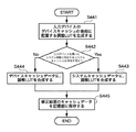
図35に示すように、先ず出力デバイスAのデバイスキャシュの後段に配置する調整LUTが生成されたとする(S431)。次に、出力デバイスAを用いたシステム特性214に対応するシステムキャッシュが記憶部202に存在するか否かを検索する(S432)。システムキャッシュが存在すれば、出力デバイスAに関連する全てのシステムキャッシュを対象として、調整LUTをシステムキャッシュの後段に合成することで修正を行う(S433)。そして、修正結果のシステムキャッシュを記憶部202に保存する(S435)。 As shown in FIG. 35, first, it is assumed that an adjustment LUT to be arranged after the device cache of the output device A is generated (S431). Next, it is searched whether or not a system cache corresponding to the system characteristic 214 using the output device A exists in the storage unit 202 (S432). If the system cache exists, all the system caches related to the output device A are targeted, and the adjustment LUT is synthesized at the subsequent stage of the system cache (S433). Then, the system cache of the correction result is stored in the storage unit 202 (S435).
このように、出力デバイスAの後段LUTを生成した場合、出力デバイスAを用いる全てのシステムキャッシュを修正して、出力デバイスAに関わるカラー変換の高速化を同時に実現することができる。その際、出力デバイスAのCMYK→XYZ関係データの更新と、出力デバイスAのデバイスキャッシュの更新に関連するシステムキャッシュの再構成は不要である。 As described above, when the latter LUT of the output device A is generated, all the system caches using the output device A can be corrected, and the speed of color conversion related to the output device A can be simultaneously realized. At that time, it is not necessary to reconfigure the system cache related to the update of the CMYK → XYZ relation data of the output device A and the update of the device cache of the output device A.
既に述べたように、出力デバイスAを用いたシステム特性214に対応するシステムキャッシュがない場合は、同一の調整LUTをデバイスキャッシュに合成し修正して記憶部202に保存する(S434)。これにより、出力デバイスAのCMYK→XYZ関係データの更新なしに、新たに出力デバイスAを用いるカラー変換のデバイスキャッシュを更新することができる。
As already mentioned, if there is no system cache that corresponds to the
実施例6において既に説明したように、入力側前段の調整LUTを更新した場合、デバイスキャッシュの更新なしに、システムキャッシュを更新して、正確なカラーマッチングを行うことができる。 As already described in Example 6, when updating the adjustment LUT input side front stage, without the device cache update, update the system cache, it is possible to perform accurate color matching.
上記の例えば入力デバイスBを想定した場合、入力デバイスBに関わるすべてのカラー変換の高速化を同時に実現できることを説明する。 For example, assuming the input device B as described above, it will be described that all color conversions related to the input device B can be accelerated at the same time.
図36に示すように、先ず入力デバイスBのデバイスキャッシュの前段に配置される調整LUTが生成されたとする(S441)。次に、入力デバイスBを用いたシステム特性214に対応するシステムキャッシュが記憶部202に存在する否かを検索する(S442)。システムキャッシュが存在すれば、入力デバイスBに関連する全てのシステムキャッシュを対象として、調整LUTをシステムキャッシュの前段に合成することで修正を行う(S443)。そして、修正結果のシステムキャッシュを記憶部202に保存する(S445)。 As shown in Figure 36, first, the adjustment LUT disposed in front stage of the input device B device cache is generated (S441). Next, it is searched whether or not the system cache corresponding to the system characteristic 214 using the input device B exists in the storage unit 202 (S442). If there is a system cache, as for all of the system cache associated with the input device B, to correct by combining adjustment LUT prior stage system cache (S443). Then, the system cache of the correction result is stored in the storage unit 202 (S445).
このように、入力デバイスBの後段LUTを生成した場合、入力デバイスBを用いる全てのシステムキャッシュを修正して、入力デバイスBに関わるカラー変換の高速化を同時に実現できる。その際、入力デバイスBのXYZ→RGB関係データの更新と、入力デバイスBのデバイスキャッシュの更新に関連するシステムキャッシュの再構成は不要である。 As described above, when the subsequent LUT of the input device B is generated, all the system caches using the input device B can be corrected, and the color conversion related to the input device B can be accelerated at the same time. At this time, it is not necessary to reconfigure the system cache related to the update of the XYZ → RGB related data of the input device B and the update of the device cache of the input device B.
既に述べたように、入力デバイスBを用いたシステム特性214に対応するシステムキャッシュがない場合は、同一の調整LUTをデバイスキャッシュに合成し修正して記憶部202に保存する(S444)。これにより、入力デバイスBのXYZ→RGB関係データの更新なしに、新たに入力デバイスBを用いるカラー変換のデバイスキャッシュを更新することができる。
As already mentioned, if there is no to that system cache corresponding to
[変形例]
上記では、調整LUTが一つのLUTである例を説明したが、調整LUT は、同一の入出力色空間インタフェイスを有する複数のLUTから構成され、一つのLUTと同等の機能を実現するものでもよい。
[Modification]
In the above, an example in which the adjustment LUT is one LUT has been described. However, the adjustment LUT is composed of a plurality of LUTs having the same input / output color space interface, and realizes a function equivalent to one LUT. Good.
また、上記では、色変換機能をもつモジュールをLUTとして記述したが、LUTでなく、変換マトリクス、または、変換アルゴリズムを備えるプログラムなどの変換モジュールでも、上記の方法によって、プリンタの特性変動に対応することができる。 In the above description, a module having a color conversion function is described as an LUT. However, a conversion module such as a conversion matrix or a program having a conversion algorithm can cope with printer characteristic fluctuations by the above method. be able to.
[他の実施例]
なお、本発明は、複数の機器(例えばホストコンピュータ、インタフェイス機器、リーダ、プリンタなど)から構成されるシステムに適用しても、一つの機器からなる装置(例えば、複写機、ファクシミリ装置など)に適用してもよい。
[Other embodiments]
Note that the present invention can be applied to a system including a plurality of devices (for example, a host computer, an interface device, a reader, and a printer), and a device (for example, a copying machine and a facsimile device) including a single device. You may apply to.
また、本発明の目的は、上記実施例の機能を実現するソフトウェアを記録した記憶媒体(記録媒体)をシステムまたは装置に供給し、そのシステムまたは装置のコンピュータ(CPUやMPU)が前記ソフトウェアを実行することでも達成される。この場合、記憶媒体から読み出されたソフトウェア自体が上記実施例の機能を実現することになり、そのソフトウェアを記憶した記憶媒体は本発明を構成する。 Another object of the present invention is to supply a storage medium (recording medium) that records software for realizing the functions of the above-described embodiments to a system or apparatus, and a computer (CPU or MPU) of the system or apparatus executes the software. Is also achieved. In this case, the software itself read from the storage medium realizes the functions of the above-described embodiments, and the storage medium storing the software constitutes the present invention.
また、前記ソフトウェアの実行により上記機能が実現されるだけでなく、そのソフトウェアの指示により、コンピュータ上で稼働するオペレーティングシステム(OS)などが実際の処理の一部または全部を行い、それによって上記機能が実現される場合も含む。 In addition, the above functions are not only realized by the execution of the software, but an operating system (OS) running on a computer performs part or all of the actual processing according to the instructions of the software, and thereby the above functions This includes the case where is realized.
また、前記ソフトウェアがコンピュータに接続された機能拡張カードやユニットのメモリに書き込まれ、そのソフトウェアの指示により、前記カードやユニットのCPUなどが実際の処理の一部または全部を行い、それによって上記機能が実現される場合も含む。 In addition, the software is written in a function expansion card or unit memory connected to the computer, and the CPU of the card or unit performs part or all of the actual processing according to instructions of the software, thereby This includes the case where is realized.
本発明を前記記憶媒体に適用する場合、その記憶媒体には、先に説明したフローチャートに対応するソフトウェアが格納される。 When the present invention is applied to the storage medium, the storage medium stores software corresponding to the flowchart described above.
Claims (5)
前記入力または出力デバイスごとに、かつ、変換設定ごとに作成された前記入力変換用の入力変換テーブルおよび前記出力変換用の出力変換テーブル、並びに、前記色域変換用の変換テーブルを統合した統合変換テーブルを使用して、前記入力データに前記色変換を施す色変換ステップと、
前記入力デバイスの色再現特性の変動を補正する入力変換調整テーブルを作成する第一の作成ステップと、
前記入力デバイスに関連する統合変換テーブルがメモリに存在する場合は当該統合変換テーブルと、前記入力変換調整テーブルを合成して、前記統合変換テーブルの前段に前記入力変換調整テーブルを配置した場合の変換特性をもつ統合変換テーブルを生成し、前記入力デバイスに関連する統合変換テーブルが前記メモリに存在しない場合は前記メモリに存在する前記入力デバイスに関連する入力変換テーブルと、前記入力変換調整テーブルを合成して、前記入力変換テーブルの前段に前記入力変換調整テーブルを配置した場合の変換特性をもつ入力変換テーブルを生成する第一の生成ステップと、
前記出力デバイスの色再現特性の変動を補正する出力変換調整テーブルを作成する第二の作成ステップと、
前記出力デバイスに関連する統合変換テーブルが前記メモリに存在する場合は当該統合変換テーブルと、前記出力変換調整テーブルを合成して、前記統合変換テーブルの後段に前記出力変換調整テーブルを配置した場合の変換特性をもつ統合変換テーブルを生成し、前記出力デバイスに関連する統合変換テーブルが前記メモリに存在しない場合は前記メモリに存在する前記出力デバイスに関連する出力変換テーブルと、前記出力変換調整テーブルを合成して、前記出力変換テーブルの後段に前記出力変換調整テーブルを配置した場合の変換特性をもつ出力変換テーブルを生成する第二の生成ステップとを有することを特徴とする色処理方法。 The input data of a color space dependent on the input device, the input conversion for converting the data of a color space independent of the device, the gamut conversion for converting the data of the color gamut of the output device, the data of a color space depending on the output device A color processing method for performing color conversion including output conversion to be converted into
Integrated conversion that integrates the input conversion table for input conversion, the output conversion table for output conversion , and the conversion table for color gamut conversion created for each input or output device and for each conversion setting using tables, and facilities to the color conversion step of the color conversion to the input data,
A first generation step of generating an input conversion adjustment table for correcting the variation of color reproduction characteristic of the input device,
When the integrated conversion table related to the input device exists in the memory, the integrated conversion table and the input conversion adjustment table are combined, and the conversion when the input conversion adjustment table is arranged in the preceding stage of the integrated conversion table An integrated conversion table having characteristics is generated, and if the integrated conversion table related to the input device does not exist in the memory, the input conversion table related to the input device existing in the memory and the input conversion adjustment table are combined A first generation step of generating an input conversion table having a conversion characteristic when the input conversion adjustment table is arranged in a preceding stage of the input conversion table;
A second creation step of creating an output conversion adjustment table for correcting variations in color reproduction characteristics of the output device;
When the integrated conversion table related to the output device exists in the memory, the integrated conversion table and the output conversion adjustment table are combined, and the output conversion adjustment table is arranged at the subsequent stage of the integrated conversion table. Generating an integrated conversion table having conversion characteristics, and if an integrated conversion table associated with the output device does not exist in the memory, an output conversion table associated with the output device existing in the memory, and the output conversion adjustment table; And a second generation step of generating an output conversion table having a conversion characteristic when the output conversion adjustment table is arranged after the output conversion table .
前記メモリに存在する前記入力デバイスに関連する入力変換テーブルと、前記入力調整テーブルを合成して、前記入力変換テーブルの後段に前記入力調整テーブルを配置した場合の変換特性をもつ入力変換テーブルを生成する第三の生成ステップとを有することを特徴とする請求項1に記載された色処理方法。 A third creation step for creating an input adjustment table for adjusting the color reproduction characteristics of the input device;
The input conversion table related to the input device existing in the memory and the input adjustment table are combined to generate an input conversion table having conversion characteristics when the input adjustment table is arranged at the subsequent stage of the input conversion table. color treatment method according to claim 1, characterized in that the organic and a third generation step of the.
前記メモリに存在する前記出力デバイスに関連する出力変換テーブルと、前記出力調整テーブルを合成して、前記出力変換テーブルの前段に前記出力調整テーブルを配置した場合の変換特性をもつ出力変換テーブルを生成する第四の生成ステップとを有することを特徴とする請求項1または請求項2に記載された色処理方法。 A fourth creation step for creating an output adjustment table for adjusting the color reproduction characteristics of the output device;
The output conversion table related to the output device existing in the memory and the output adjustment table are combined to generate an output conversion table having conversion characteristics when the output adjustment table is arranged in the preceding stage of the output conversion table. color processing method according to claim 1 or claim 2, characterized in that organic and a fourth generation step of.
前記入力または出力デバイスごとに、かつ、変換設定ごとに作成された、前記入力変換用の入力変換テーブルおよび前記出力変換用の出力変換テーブル、並びに、前記色域変換用の変換テーブルを統合した統合変換テーブルを使用して、前記入力データ前記色変換を施す色変換手段と、
前記入力デバイスの色再現特性の変動を補正する入力変換調整テーブルを作成する第一の作成手段と、
前記入力デバイスに関連する統合変換テーブルがメモリに存在する場合は当該統合変換テーブルと、前記入力変換調整テーブルを合成して、前記統合変換テーブルの前段に前記入力変換調整テーブルを配置した場合の変換特性をもつ統合変換テーブルを生成し、前記入力デバイスに関連する統合変換テーブルが前記メモリに存在しない場合は前記メモリに存在する前記入力デバイスに関連する入力変換テーブルと、前記入力変換調整テーブルを合成して、前記入力変換テーブルの前段に前記入力変換調整テーブルを配置した場合の変換特性をもつ入力変換テーブルを生成する第一の生成手段と、
前記出力デバイスの色再現特性の変動を補正する出力変換調整テーブルを作成する第二の作成手段と、
前記出力デバイスに関連する統合変換テーブルが前記メモリに存在する場合は当該統合変換テーブルと、前記出力変換調整テーブルを合成して、前記統合変換テーブルの後段に前記出力変換調整テーブルを配置した場合の変換特性をもつ統合変換テーブルを生成し、前記出力デバイスに関連する統合変換テーブルが前記メモリに存在しない場合は前記メモリに存在する前記出力デバイスに関連する出力変換テーブルと、前記出力変換調整テーブルを合成して、前記出力変換テーブルの後段に前記出力変換調整テーブルを配置した場合の変換特性をもつ出力変換テーブルを生成する第二の修正手段とを有することを特徴とする色処理装置。 The input data of a color space dependent on the input device, the input conversion for converting the data of a color space independent of the device, the gamut conversion for converting the data of the color gamut of the output device, the data of a color space depending on the output device A color processing device that performs color conversion including output conversion to be converted into
For each of the input or output device integration, and is created for each conversion setting, the output conversion table for the input conversion table and the output conversion for the input conversion, as well, that integrates a conversion table of the color gamut conversion for using a transformation table, and facilities to the color conversion means the input data the color conversion,
First creation means for creating an input conversion adjustment table for correcting a variation in color reproduction characteristics of the input device ;
When the integrated conversion table related to the input device exists in the memory, the integrated conversion table and the input conversion adjustment table are combined, and the conversion when the input conversion adjustment table is arranged in the preceding stage of the integrated conversion table An integrated conversion table having characteristics is generated, and if the integrated conversion table related to the input device does not exist in the memory, the input conversion table related to the input device existing in the memory and the input conversion adjustment table are combined A first generation means for generating an input conversion table having a conversion characteristic when the input conversion adjustment table is arranged in a preceding stage of the input conversion table;
Second creation means for creating an output conversion adjustment table for correcting variations in color reproduction characteristics of the output device;
When the integrated conversion table related to the output device exists in the memory, the integrated conversion table and the output conversion adjustment table are combined, and the output conversion adjustment table is arranged at the subsequent stage of the integrated conversion table. Generating an integrated conversion table having conversion characteristics, and when an integrated conversion table associated with the output device does not exist in the memory, an output conversion table associated with the output device existing in the memory, and the output conversion adjustment table; And a second correction unit that generates an output conversion table having a conversion characteristic when the output conversion adjustment table is arranged after the output conversion table .
Priority Applications (2)
| Application Number | Priority Date | Filing Date | Title |
|---|---|---|---|
| JP2005262985A JP4522346B2 (en) | 2005-09-09 | 2005-09-09 | Color processing method and apparatus |
| US11/470,688 US7697167B2 (en) | 2005-09-09 | 2006-09-07 | Color processing method and apparatus |
Applications Claiming Priority (1)
| Application Number | Priority Date | Filing Date | Title |
|---|---|---|---|
| JP2005262985A JP4522346B2 (en) | 2005-09-09 | 2005-09-09 | Color processing method and apparatus |
Publications (3)
| Publication Number | Publication Date |
|---|---|
| JP2007081480A JP2007081480A (en) | 2007-03-29 |
| JP2007081480A5 JP2007081480A5 (en) | 2008-10-09 |
| JP4522346B2 true JP4522346B2 (en) | 2010-08-11 |
Family
ID=37854733
Family Applications (1)
| Application Number | Title | Priority Date | Filing Date |
|---|---|---|---|
| JP2005262985A Expired - Fee Related JP4522346B2 (en) | 2005-09-09 | 2005-09-09 | Color processing method and apparatus |
Country Status (2)
| Country | Link |
|---|---|
| US (1) | US7697167B2 (en) |
| JP (1) | JP4522346B2 (en) |
Families Citing this family (31)
| Publication number | Priority date | Publication date | Assignee | Title |
|---|---|---|---|---|
| KR101225059B1 (en) * | 2006-02-24 | 2013-01-23 | 삼성전자주식회사 | Apparatus and method for enhancing color device-adaptively |
| JP2007274584A (en) * | 2006-03-31 | 2007-10-18 | Canon Inc | Color processing method and device thereof |
| JP2009117991A (en) * | 2007-11-02 | 2009-05-28 | Fujifilm Corp | Image conversion apparatus and image conversion program |
| JP4974113B2 (en) * | 2007-12-06 | 2012-07-11 | 京セラドキュメントソリューションズ株式会社 | Calibration apparatus, calibration method, and calibration program |
| US20090184976A1 (en) * | 2008-01-22 | 2009-07-23 | Alcatel-Lucent | System and Method for Color-Compensating a Video Signal Having Reduced Computational Requirements |
| US8129669B2 (en) * | 2008-01-22 | 2012-03-06 | Alcatel Lucent | System and method generating multi-color light for image display having a controller for temporally interleaving the first and second time intervals of directed first and second light beams |
| US8237735B2 (en) * | 2008-01-22 | 2012-08-07 | Xerox Corporation | Caching for color management systems performing a gamut mapping function |
| JP4666069B2 (en) * | 2008-02-18 | 2011-04-06 | 富士ゼロックス株式会社 | Color correction coefficient generating apparatus and program |
| JP4972014B2 (en) * | 2008-03-04 | 2012-07-11 | キヤノン株式会社 | Image processing apparatus and image processing method |
| JP2010056794A (en) * | 2008-08-27 | 2010-03-11 | Canon Inc | Chart for multi-color calibration, and image processing method and image processing apparatus using the chart |
| JP5142890B2 (en) * | 2008-08-27 | 2013-02-13 | キヤノン株式会社 | Image processing method and image processing apparatus |
| JP5253047B2 (en) * | 2008-09-01 | 2013-07-31 | キヤノン株式会社 | Color processing apparatus and method |
| EP2342891B1 (en) | 2008-10-02 | 2018-11-14 | Canon Kabushiki Kaisha | Image processing apparatus and color processing method |
| JP5123809B2 (en) * | 2008-10-02 | 2013-01-23 | キヤノン株式会社 | Image processing apparatus and color processing method |
| JP5268542B2 (en) * | 2008-10-02 | 2013-08-21 | キヤノン株式会社 | Image processing apparatus and color processing method |
| JP5329920B2 (en) * | 2008-10-30 | 2013-10-30 | キヤノン株式会社 | Color processing apparatus and method |
| JP5153607B2 (en) * | 2008-12-22 | 2013-02-27 | キヤノン株式会社 | Image processing apparatus, image processing method, and image processing program |
| US8831343B2 (en) * | 2009-01-19 | 2014-09-09 | Dolby Laboratories Licensing Corporation | Image processing and displaying methods for devices that implement color appearance models |
| WO2010103983A1 (en) | 2009-03-11 | 2010-09-16 | Canon Kabushiki Kaisha | Image processing apparatus and color processing method |
| JP2011023833A (en) * | 2009-07-13 | 2011-02-03 | Fuji Xerox Co Ltd | Image reader, image formation device, and program |
| KR101356370B1 (en) * | 2009-07-31 | 2014-01-27 | 엘지디스플레이 주식회사 | Method of Correcting Data And Liquid Crystal Display Using The Same |
| US8576439B2 (en) * | 2009-12-31 | 2013-11-05 | Konica Minolta Laboratory U.S.A., Inc. | Method for calculating color transform in WCS pipeline |
| JP5440195B2 (en) * | 2010-01-15 | 2014-03-12 | コニカミノルタ株式会社 | Color profile creation method, image processing apparatus for creating color profile, and control program for image processing apparatus |
| JP5630112B2 (en) * | 2010-07-15 | 2014-11-26 | 富士ゼロックス株式会社 | Color conversion coefficient generation device, color reproduction characteristic correction device, and program |
| US10403229B2 (en) | 2012-03-08 | 2019-09-03 | Nec Corporation | System and method for reproducing color image with supposed reproduced color gamuts |
| US11205399B2 (en) | 2012-03-08 | 2021-12-21 | Nec Corporation | Color reproduction method, color reproduction system, color reproduction program, and color reproduction apparatus |
| WO2018123340A1 (en) * | 2016-12-27 | 2018-07-05 | ソニー株式会社 | Product design system and design image correction apparatus |
| WO2019117919A1 (en) * | 2017-12-14 | 2019-06-20 | Hewlett-Packard Development Company, L.P. | Generating an area coverage vector |
| JP7436951B2 (en) | 2019-11-27 | 2024-02-22 | 京セラドキュメントソリューションズ株式会社 | Image forming apparatus, image forming method, and image forming program |
| JP2022062886A (en) * | 2020-10-09 | 2022-04-21 | セイコーエプソン株式会社 | Printing apparatus and printing method |
| DE102021208206A1 (en) * | 2021-07-29 | 2023-02-02 | Heidelberger Druckmaschinen Aktiengesellschaft | Process for transforming color spaces |
Citations (2)
| Publication number | Priority date | Publication date | Assignee | Title |
|---|---|---|---|---|
| JP2001119593A (en) * | 1999-10-19 | 2001-04-27 | Kyocera Mita Corp | Image forming device |
| JP2003008915A (en) * | 2001-06-26 | 2003-01-10 | Seiko Epson Corp | Image processor, method, program and recording medium |
Family Cites Families (8)
| Publication number | Priority date | Publication date | Assignee | Title |
|---|---|---|---|---|
| JP3209757B2 (en) * | 1991-05-30 | 2001-09-17 | キヤノン株式会社 | Color correction method |
| US5502580A (en) | 1993-10-06 | 1996-03-26 | Fuji Photo Film Co., Ltd. | Color reproduction system |
| JP3504975B2 (en) * | 1993-10-06 | 2004-03-08 | 富士写真フイルム株式会社 | Color reproduction system |
| JPH11326056A (en) * | 1998-05-19 | 1999-11-26 | Silver Seiko Ltd | Color proofer and its calibration method |
| US6894806B1 (en) * | 2000-03-31 | 2005-05-17 | Eastman Kodak Company | Color transform method for the mapping of colors in images |
| JP3956091B2 (en) * | 2001-03-26 | 2007-08-08 | セイコーエプソン株式会社 | Computer-readable recording medium recording color conversion program, method for creating color conversion table, computer-readable recording medium recording color conversion table data, color conversion apparatus, color conversion program, color conversion method, and color conversion table |
| KR100736939B1 (en) * | 2005-10-08 | 2007-07-10 | 삼성전자주식회사 | Intelligence type color gamut management method |
| KR100679048B1 (en) * | 2005-10-14 | 2007-02-06 | 삼성전자주식회사 | Method and apparatus for gamut mapping |
-
2005
- 2005-09-09 JP JP2005262985A patent/JP4522346B2/en not_active Expired - Fee Related
-
2006
- 2006-09-07 US US11/470,688 patent/US7697167B2/en not_active Expired - Fee Related
Patent Citations (2)
| Publication number | Priority date | Publication date | Assignee | Title |
|---|---|---|---|---|
| JP2001119593A (en) * | 1999-10-19 | 2001-04-27 | Kyocera Mita Corp | Image forming device |
| JP2003008915A (en) * | 2001-06-26 | 2003-01-10 | Seiko Epson Corp | Image processor, method, program and recording medium |
Also Published As
| Publication number | Publication date |
|---|---|
| US7697167B2 (en) | 2010-04-13 |
| US20070058181A1 (en) | 2007-03-15 |
| JP2007081480A (en) | 2007-03-29 |
Similar Documents
| Publication | Publication Date | Title |
|---|---|---|
| JP4522346B2 (en) | Color processing method and apparatus | |
| JP3305265B2 (en) | Image processing apparatus and method | |
| JP3634633B2 (en) | Image processing apparatus and method | |
| JP3291259B2 (en) | Image processing method and recording medium | |
| JP4592090B2 (en) | Color processing method and apparatus | |
| US20070058186A1 (en) | Image Processing Apparatus, Image Processing Method, Image Processing Program, And Storage Medium | |
| US7230737B1 (en) | Image processing method and apparatus | |
| JP2006254371A (en) | Color processing device and its method | |
| JP2005354372A (en) | Apparatus and method for image recording device, method and system for image processing | |
| JP3805247B2 (en) | Image processing apparatus and method | |
| US8115978B2 (en) | Information processing method and information processing apparatus for simulating a result output from a first output device based on input data represented in a color space that is dependent on the input device by a second output device | |
| JP5156423B2 (en) | Color processing apparatus and color processing method | |
| JP3305266B2 (en) | Image processing method | |
| JP2009071618A (en) | Image processor, image processing method and program, and recording medium | |
| JP2007174126A (en) | Image processing apparatus and method | |
| JP2001309198A (en) | Image processing method | |
| JP4533291B2 (en) | Color processing method and apparatus | |
| JP2007074557A (en) | Image processing method, image processing apparatus, computer program, and storage medium | |
| JP3311295B2 (en) | Image processing apparatus and method | |
| JP2006238335A (en) | Information processing method | |
| JP3535778B2 (en) | Image processing method, apparatus and recording medium | |
| JP3667171B2 (en) | Image processing method, apparatus, and recording medium | |
| JP2004072758A (en) | Color processing apparatus, color processing method, and color processing program | |
| JP2002077652A (en) | Image processing method and recording medium | |
| JP2002271645A (en) | Image processing method and image processor |
Legal Events
| Date | Code | Title | Description |
|---|---|---|---|
| A521 | Request for written amendment filed |
Free format text: JAPANESE INTERMEDIATE CODE: A523 Effective date: 20080825 |
|
| A621 | Written request for application examination |
Free format text: JAPANESE INTERMEDIATE CODE: A621 Effective date: 20080825 |
|
| A977 | Report on retrieval |
Free format text: JAPANESE INTERMEDIATE CODE: A971007 Effective date: 20091102 |
|
| A131 | Notification of reasons for refusal |
Free format text: JAPANESE INTERMEDIATE CODE: A131 Effective date: 20091109 |
|
| A521 | Request for written amendment filed |
Free format text: JAPANESE INTERMEDIATE CODE: A523 Effective date: 20100106 |
|
| TRDD | Decision of grant or rejection written | ||
| A01 | Written decision to grant a patent or to grant a registration (utility model) |
Free format text: JAPANESE INTERMEDIATE CODE: A01 Effective date: 20100517 |
|
| A01 | Written decision to grant a patent or to grant a registration (utility model) |
Free format text: JAPANESE INTERMEDIATE CODE: A01 |
|
| A61 | First payment of annual fees (during grant procedure) |
Free format text: JAPANESE INTERMEDIATE CODE: A61 Effective date: 20100525 |
|
| R150 | Certificate of patent or registration of utility model |
Free format text: JAPANESE INTERMEDIATE CODE: R150 |
|
| FPAY | Renewal fee payment (event date is renewal date of database) |
Free format text: PAYMENT UNTIL: 20130604 Year of fee payment: 3 |
|
| LAPS | Cancellation because of no payment of annual fees |