JP4521592B2 - How to set up bidirectional optical communication between central unit and remote unit - Google Patents
How to set up bidirectional optical communication between central unit and remote unit Download PDFInfo
- Publication number
- JP4521592B2 JP4521592B2 JP2001037906A JP2001037906A JP4521592B2 JP 4521592 B2 JP4521592 B2 JP 4521592B2 JP 2001037906 A JP2001037906 A JP 2001037906A JP 2001037906 A JP2001037906 A JP 2001037906A JP 4521592 B2 JP4521592 B2 JP 4521592B2
- Authority
- JP
- Japan
- Prior art keywords
- frame
- remote unit
- unit
- central unit
- transmission
- Prior art date
- Legal status (The legal status is an assumption and is not a legal conclusion. Google has not performed a legal analysis and makes no representation as to the accuracy of the status listed.)
- Expired - Fee Related
Links
Images


Classifications
-
- H—ELECTRICITY
- H04—ELECTRIC COMMUNICATION TECHNIQUE
- H04L—TRANSMISSION OF DIGITAL INFORMATION, e.g. TELEGRAPHIC COMMUNICATION
- H04L5/00—Arrangements affording multiple use of the transmission path
- H04L5/14—Two-way operation using the same type of signal, i.e. duplex
-
- H—ELECTRICITY
- H04—ELECTRIC COMMUNICATION TECHNIQUE
- H04B—TRANSMISSION
- H04B10/00—Transmission systems employing electromagnetic waves other than radio-waves, e.g. infrared, visible or ultraviolet light, or employing corpuscular radiation, e.g. quantum communication
- H04B10/25—Arrangements specific to fibre transmission
- H04B10/2589—Bidirectional transmission
Abstract
Description
【0001】
【本発明の属する技術分野】
本発明は中央ユニットと遠隔ユニット間の両方向光通信の設定に関する。
【0002】
本発明の特に有利な応用は光ファイバ遠隔通信の分野に在り、更に詳細には2点間型アクセスネットワークの分野に関する。
【0003】
【従来の技術】
現在、光ファイバ遠隔通信において、所与の中央ユニットが所与の顧客の構内に所在する遠隔ユニットへ接続されるアクセスネットワークが知られている。この型の技術は、1つの中央ユニットが顧客側の複数の遠隔ユニットに接続可能である「1点対多点」技術と対照的に「2点間」技術として知られている。本発明は、2点間伝送に関することが好ましいが、1点対多点伝送の状況において、特に受動的な光ネットワーク(PON)型伝送にも適用可能である。
【0004】
2点間技術において最も一般に使われる通信モードは、各伝送方向毎に1つの光ファイバを使用する「シンプレックス(単向)」モードとしても知られている同時通信モードである。
【0005】
今まで、遠隔通信オペレータ、特に光ファイバを使用するオペレータは、伝送リンクの両端、即ち、1つの所定中央ユニットと1つの所定遠隔ユニットを介して制御を実施し、この場合の両ユニットは同時に設置または撤去された。オペレータにとって、この状況は、技術的な安定性が或る程度保証されていること、及び、オペレータが取り扱う顧客およびユニットに関して当該オペレータが奪うことのできない権利を有することを意味した。
【0006】
【発明が解決しようとする課題】
今日では、光電子部品技術の分野において起きた変化、光ファイバ遠隔通信市場における競争の導入、及び、例えば波長分割多重化(WDM)のような新規技法の出現によって、オペレータによる操作はかなり変化した。概略的には、WDMは光アルセクネットワークにおいて以前に使用された技術とは次の点で異なる。光ファイバアクセスネットワークにおいて現在使用されている周知の技法においては、中央ユニットと全ての顧客遠隔ユニットとの間において、約1.3μm又は1.5μmを中心とするスペクトル窓内において選択される1つ又は2つの波長を、広帯域型の各種ユニットの形態をとる光電子部品で、実現するが、これに対して、WDM技法においては、少なくとも中央ユニットにおける、好ましくは1.5μmを中心とする窓が、それぞれ特定の遠隔ユニットに割当てられる複数の搬送波長に細分化される。例えば、稠密な波長分割多重化(DWDM)において、1.48μmから1.58μmまでの範囲に亙る1.5umを中心とする窓は64個の搬送波長チャネルに細分化される。実際には、各遠隔ユニットは、当該ユニットに割当てられたチャネルに中心を置くフィルタを装備可能であり、中央ユニットは、各搬送波長における放射に適した1つ又は複数の同調可能レーザを備える。
【0007】
この新規な状況の結果として、オペレータ自身の中央ユニットとオペレータの顧客の遠隔ユニットとの間に或る程度の相互運用性(インタオペラビリティ)に対応する義務がオペレータに負わせられた。この相互運用性は、メーカに競合させることによって部品の価格を下げ、供給源の多様化を可能にするので、更に詳細な多数の利点を提供する。更に、相互運用性は、例えばWDMなどの新規技法の導入を更に容易にする。最終的に、ユニット間における独立性が得られるので、オペレータは、もはやリンクの両端部における全てのユニットの日常管理に責任を負うことなく、ユニットの幾つかのみを交換する場合における整合性(コンシステンシ)を維持する必要性もない。
【0008】
それでもなお、相互運用性は、中央ユニットと遠隔ユニットが、メーカのアイデンティティ(独自性)及びメーカ独特の設計判断とは無関係に接続できることを可能にする。都合の悪いことに、オペレータは中央ユニットを担当したままの状態であるが、ネットワークへ接続されるべき遠隔ユニット、特に遠隔ユニットの通信モードに関する当該オペレータの知識は必ずしも十分に信頼できない。
【0009】
【課題を解決するための手段】
従って本発明の主題によって解決されるべき技術的問題は、中央ユニットと、遠隔ユニットとの間で両方向光通信を設定する方法であって、複数の通信モードから選定された所与の通信モードにおいて作動可能な遠隔ユニットの実装に関して出来るだけ多くの技術的変形とインタフェース可能にするように、中央ユニットが接続されるべき遠隔ユニットの型を「ブラインド」的に、即ち人的介入なしに、検出可能にし、かつ、例えばWDMのような新規技法に適応可能である方法を提供するとことにある。
【0010】
本発明によれば、提示された技術的問題に対する解決策は、次に示すステップを含む方法によって構成される。
中央ユニットにおいて、各フレームパターンが前記通信モードの1つに適するような複数のフレームパターンを画定するステップ、及び
整合性のある(コヒーレントな)応答が前記遠隔ユニットから得られる時まで前記複数のフレームパターンを順次に送るステップとを含み、遠隔ユニットの通信モードは前記の整合性のある応答を起こさせるフレームパターンに対応するモードである。
【0011】
従って、本発明の方法は、伝送開始に際して、当該伝送全体に亙ってどのフレームパターンが使用されるべきかを決定するように、中央ユニットが遠隔ユニットの通信モードを自動的に識別可能にする。
【0012】
従って、本発明は、通信リンクの2つの端部の間において、可能な限り広い互換性を達成し、かつ、既存技術、および、技術発展の各段階において、中央ユニット用の新規電子装置の開発の必要なしにWDMなどの、将来技術への完全な適応性を達成する。
【0013】
当然のことながら、本発明の方法は全ての通信モードに適用され、特に同時通信を含むモード及び交互通信を含むモードで構成される複数の通信モードに適用される。例を挙げれば、一方、同時通信モードには、シンプレックス(単向)、フルデュプレックス(全二重)、及び、ダイプレップス(単向2路)モードが含まれ、他方、交互通信モードには、ハーフデュプレクス(半二重)およびパートデュプレクス(部分二重)モードが含まれる。
【0014】
以下に詳細に説明される本発明の実施において、同時通信モードに適するフレームパターンは、伝送中断なしの完全フレーム、従って、遠隔ユニットの応答は非同期的に送られるフレームによって構成される。
【0015】
同様に、本発明は、中央ユニットからの伝送中断と当該フレームの終端部との間に遠隔ユニットによる送信を可能にするために伝送が中断されるようなフレームによって構成される交互通信モードに適したフレーム構成を提供する。遠隔ユニットが反射変調器である特定の場合において、フレームは、伝送が中断された後で、前記遠隔ユニットによる変調および反射されるための一定のレベルによって構成される。
【0016】
WDM技法が適用されると、中央ユニットは、各遠隔ユニットに割当てられた波長において送信しなければならない。都合が悪いことには、この波長が操作開始されたときに、当該システムにとってこの波長が必ずしも既知であるとは限らない。従って、本発明の方法には、中央ユニットが交信しようとしている遠隔ユニットに割当てられている波長を自動的に探索する手順が含まれることが有利である。この目的に関しては、2つの可能な実装が提供される。
【0017】
第1の実装において、波長によって識別される遠隔ユニットに関して、複数のフレームパターンを順次に送るステップは、前記の整合性のある応答が得られるまで、各遠隔ユニット波長において逐次的に実施される。
【0018】
第2の実装において、波長によって識別される遠隔ユニットに関して、複数のフレームパターンを順次に送るステップは、前記の整合性のある応答が得られるまで、各フレームパターンに関する各遠隔ユニット波長において逐次的に実施される。
【0019】
限定的意味を持たない例として記載されている添付図面に関する次の記述は、本発明の内容および実現方法を明らかにするはずである。
【0020】
【発明の実施の形態】
図1aは中央ユニット10と遠隔ユニット20との間の光ファイバリンク1を示す。この例において、ユニット10及び20は、各々が第1にそれぞれのエミッタ12又は22によって構成される二重タイプであり、前記エミッタは波長λのレーザダイオードであることが好ましいく、第2にそれぞれの検出器13、23によって構成され、詳細には、前記検出器は波長λに感応するフォトダイオードによって構成される。図1aに示すように、各ユニットによって放射および受け取られる光線はそれぞれ半反射板11、21によって分離される。
【0021】
図1aに示す二重タイプユニットは、例えば半二重およびその変種としての部分的二重タイプのような交互通信モードに良好に適応する。半二重モードは、ファイバ1を介して情報を遠隔ユニット20に送ることによって始まり、その後で情報を中央ユニット10へ送ることによって構成される。この通信モードは、ファイバ1を介した伝播時間も考慮する必要があるので、一方向に情報を伝送するために必要な伝送速度の2倍以上の伝送速度を必要とする。中央ユニット10が送信と受信を同時に実施可能であるものとすれば、部分的二重モードは伝播時間を無視することを可能にする。そうするには、2つのユニット10と20との間の伝播時間を算定し、遠隔ユニット20の入り口における動作が排他的に交互であることを保証する仕方において情報の送信に適応するようにリンクを初期化することが必要である。
【0022】
図1aのデュプレクサは、検出器13、23がこれら自身のエミッタ12、22によってブラインドされないことを条件に、全二重同時通信モード用にも使用可能である。
【0023】
図1bは、ダイプレクサ(単向2路通信機)として知られている図1aのデュプレクサ(二重通信機)の一変形であり、この変種は、一方の伝送方向に波長λ1を伝達し、もう一方の伝送方向に波長λ2を伝達するために1つの単一光ファイバ1’を使用する。従って、この部品は、この場合にダイプレクスモードと呼ばれる同時通信に非常に適切である。図1bの例において、送信波長と受信波長は図1aの半反射板11、21に置き換えられるダイクロイックフィルタ11’及び21’によって分離される。ETSI及びITU−T規格の適用に際して、中央ユニット10’及び遠隔ユニット20’の波長λ1とλ2はそれぞれ約1.5μmの窓および約1.3μmの窓内に所在するように選択される。
【0024】
図1bのダイプレクサは、遠隔ユニットにおいては約1.3μmの窓内で選定された波長を使用し、中央ユニットにおいては、光ファイバkm当たりの損失が最小である窓であって、当該窓内だけにおいて光増幅器の最大可用性を表す窓である約1.5μmの窓内から選定された複数の波長を使用するWDM技法とも互換性がある。各遠隔ユニットは中央ユニットから送られる搬送波長に割当てられる。WDMはダイプレックスモード原理の拡張であり、一般的に、光リンクのビットレート容量を増大するため、又は、複数のサービス間または複数の顧客間リンクを共有するために用いられる。当然のことながら、遠隔ユニットは当該ユニット自体に割当てられ波長と連携した受信フィルタを備えなければならず、中央ユニットは、例えば、同調可能レーザによる1.5μmにおける窓内において画定される各チャネルを介して放射可能でなくてはならない。
【0025】
本発明の状況に従って使用される他の電気光学部品(図示せず)を具体的に次に示す。
可逆部品。これらは偏光に応じてエミッタ又は検出器として作動する発光ダイオード(LED)、または、レーザである。現在、これら2つの作動モードは同時実施的ではないので、2つの状態の間の切替え用として、及び、ハーフデュプレクス又はパートデュプレクス交互通信モードを使用するための電子デバイスを備えることが必要である。この型の部品の利点は、市販されている全てのレーザはこのモードにおいて作動可能であり、部品とファイバ間の結合が均一であり、これに対応して損失を減少させ、位置合わせの困難さを軽減し、従って、低コスト化を可能にする。
集積線形ダイプレクサ部品。これらは、1つの単一ファイバと直線配置されたレーザ空洞および検出器を備えたモノリシック線形構造体である。現在、これらの部品はダイプレクスモードのみに使用される。
反射部品。これらの部品は受け取り部分および入射光パワーを変調および反射するための鏡部分を備える。従って、これらの部品は、連続的な入射信号の波長である使用される波長の光を生成しないという点で受動的である。その結果、これらの部品は、WDMにおけるハーフデュプレクス又はパートデュプレクスモードに特に適する。オペレータは、波長に関して特有の様々な型の遠隔ユニットを:これらをネットワークの正しい端部と関連付け、又は、これらの温度をサーボ制御するために、管理する必要はない。当該ネットワークは、波長をクライアントに割当てる受動回路網であり、制御する必要のある安定した気候環境内に所在するのは中央ユニットのみである。ただし、放射された光パワーレベルを維持するために温度のサーボ制御が必要である。
【0026】
最後に、それぞれ単一方向伝送に専用される2つの光ファイバに依存するシンプレクス(単向)として知られている別の同時通信モードに言及しなければならない。
【0027】
使用する通信モードとは無関係にユニットの相互運用性を提供するために、中央ユニット10、10’は、両方向光通信の設定に用いられる遠隔ユニット20、20’の通信モードを識別することが可能でなければならない。
【0028】
そのためには、中央ユニット10、10’と遠隔ユニット20、20との間に両方向光通信を設定する方法が提供される。この方法は、中央ユニット10、10’において、それぞれが1つの通信モードに適用可能である複数のフレームパターンを画定し、遠隔ユニット20、20’からコヒーレントな応答が得られるまで、これらのフレームパターンを順次送信することから成る。遠隔ユニットの通信モードは、前記のコヒーレントな応答を引き起こさせるモードである。
【0029】
この方法は、オペレータが次に示す行為を実施することを可能にする。
中央ユニットの長い耐用寿命の利益を得る。
一方の通信モードからもう一方のモードへ移るための新規電子装置を開発する必要性を回避する。
遠隔ユニットを稼働状態に維持したままで、当該遠隔ユニットの型をオペレータにとって透明にし、一旦接続が確立されれば、当該遠隔ユニットが管理されるのを妨げることはない。
作動することを自動化する。
中央において、顧客とは独立してユニットを更新する。
当該ユニットが既に設置済みであることを理由とする遅延または遅鈍なしに、中央用ユニットのサプライヤ(供給者)の切り替えを可能にする。
【0030】
図2a、2b、及び、2cは、それぞれ同時、交互、および、変調された反射通信モードに適用可能なフレームの例を示す。
【0031】
図2aのフレームは、シンプレクス(単向)、フルデュプレクス(全二重)、及び、ダイプレクス(単向2路)モードに適用可能である。このフレームは、例えば、中央ユニットと物理層の状態に関する遠隔ユニットとの間で情報を交換する物理作動および保守型(PLOAM)ヘッダセルC1を有する。後続するセルC2、C3、...、Cnはデータセルであり、必要に応じて、遠隔ユニットを管理する1つ又は複数のセルを含むことが可能である。中央部分は、任意の「空」セルCn+1、...、CNで充填され、これが遠隔ユニットのクロック同期化するクロックの存在を維持するために残存することがあり得る。従って、図2aのフレームは完全であり、伝送は中断されない。
【0032】
図2bのフレームは、交互通信モードに適用され、伝送の中断と当該フレームの端部との間で遠隔ユニットが今度送信することを可能にするために伝送を中断することが必要であるということを除けば同じ原理で作動する。伝送割込みに関する情報は、中央から顧客へダウンロードされる情報を補給するセルの個数を指定することによってヘッダセルC’1内に提供され得るか、又は、その情報は、遠隔ユニットによって識別可能なフレーム終端セルC’pによって伝達可能である。第1の場合には、遠隔ユニットは、受信したセルをカウントするためにカウンタを始動し、ヘッダセルC’1内に発表されているセルの個数を一旦読み取ると、送信に切り替わる。
【0033】
パートデュプレクスモードへの適応は、遠隔ユニットにおいて交番が維持されることを保証する状態において、往復フレームがインタレースされることを可能にするように往復伝播時間を最初に算定することを除けば、特に困難は無い。この場合、フレームの長さは伝播時間の関数として適応される。
【0034】
図2cのフレームは、反射変調器によって構成された遠隔ユニット用交互モードに対応する。本フレームは、オン/オフ変調が施され、中央ユニットへの反射による戻りがこれに続く連続レベルを送信することからなる遠隔ユニットからの伝送に割当てられた部分を含む交番原理に基づく。
【0035】
図2bと同様に、本フレームの長さは必要条件に適合するように調節可能である。伝送を中断する命令は、同様にして、ヘッダセルC”lのフィールド内に、又は、遠隔ユニットによって識別されるフレーム終端セルC”pを介して与えられる。セルC”p+1からC”Nまでは1からなり、遠隔ユニットによって変調されるように作成される。
【0036】
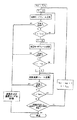
図3の流れ図は、図2a、2b、2cのフレームの実施を示す。
【0037】
初期化ステージに際して、探索サイクルの個数Ncyはゼロに設定される。搬送波長λiによって各遠隔ユニットが識別されるWDM技術を使用するものとすれば、フレームパターンは、中央ユニットの放射窓から選定される第1の波長λ0で始まり、連続して順次に送信される。
【0038】
第1のステップにおいて、中央ユニットは、放射中断セルを含まない同時通信モード(図2a)に適するフレームを送信することによって開始する。遠隔ユニットがシンプレクス、フルデュプレクス、又は、ダイプレクス型であれば、当該遠隔ユニットは、同期してヘッダセルC1を受信すると、例えばPLOAMヘッダセルで始まる中央ユニットへのセルの連続ストリームの送信を開始し、そのフレームレートで送信が繰り返される。他の全ての場合においては、当該遠隔ユニットは無音(サイレント)のままである。
【0039】
第1ステップにおいて、遠隔ユニットをコールドスタート可能にするに充分な経過時間Tmax内にコヒーレントな応答が検出されないならば、中央ユニットは、ハーフデュプレクス又はパートデュプレクス交互モード通信(図2b)用に形成されたパターンにフレームパターンを変更する。このフレームは、一実施例において中央から顧客へのダウンフレームを形成するセルの個数を指定するヘッダセルC’1で始まり、この時点において中央ユニットは送信を中断し、遠隔ユニットは自身のPLOAMセルの送信に切り替わらなければならない。このフレームは、遠隔ユニットがコールドスタートするために必要な最大期間中反復される。この期間中に中央へ入来するPLOAMセルが検出された場合には、中央は、往復伝播時間を測定した後で、パートデュプレクスにおける最適化の達成を随意試行することができる。
【0040】
許容期間内に応答が検出されない場合には、次に示す2つの可能性がある。即ち、作動可能状態にある遠隔ユニットが存在しない場合、又は、この種遠隔ユニットは存在するが、反射変調モードで作動する場合のどちらかである。次に、中央ユニットは第3のフレームパターン(図2c)を送る。これ最後のステップに許容された時限内に満足のゆく応答が無い場合には、オペレータは、手順を停止すること、又は、探索サイクルの個数Ncyを増大することによって、事前決定済みの所定最大個数に到達するまで当該プロセスの反復を試行することのいずれかが可能である。
【0041】
WDM技術が用いられる場合には、サイクルの終端における搬送波長を変更し、ダウンフレーム分析を再開することも可能なはずである。WDM操作は、第1の波長λ0を受け取ると即刻応答する広帯域部品を使用する通常の技法と互換性を持つことに留意されたい。最後に、送信されたフレームパターンの各型に対する波長をスキャンすることによってWDMを考慮することが可能であることにも言及しなければならない。
【0042】
図3の流れ図に示すステップのシークエンスは表示の一例である。上記のシークエンスは、更に有利であるはずの他のシークエンスを除外するものではない。特に、交互通信モードに適したフレームの送信によって中央が操作を開始することは構想可能である。ただし、これは、次に示す特定条件の下においてのみ可能である。
− アドレスされたときには各々の型が応答できるように、ハーフデュプレクスユニットがフルデュプレクスユニットと識別されることを可能にするソフトウェアを遠隔ユニットが実行する場合。伝送中断セルまたはダウンフレームのPLOAMセル内のその番号が当該フレームの最後のセルと合致するかどうかを単に検出することによって、この種のソフトウェアは構成可能なはずである。中央ユニットがフレームを送信中である状態において、遠隔ユニットは、当該フレームを構成するセルの個数を決定可能である。従って、中断セル又はPLOAMセルにおいて指定された最後のペイロードセルの番号が当該フレームの最後のセルと合致するかどうかを検査することが容易である。従って、フルデュプレクスユニットは、これらの数が一致するばあいに限り送信を開始するが、これとは反対に、ハーフデュプレクスユニットは、反対の情況の下においてのみ再送信を開始する。 −或いは、所定のフレームパターンの送信が認可済みであるかどうかを遠隔ユニットが判断するように、どのフレームパターンを使用中であるかを明確に表明するために、PLOAMセルにおいて特殊フィールドが用いられる場合。
−或いは、遠隔ユニットによって返されたフレームを中央ユニットが詳細に分析する場合。稼働開始に際して、フルデゥプレクスユニットは中央ユニットにアドレスされた連続フレームを生成し、他方、ハーフデゥプレクスユニットは当該フレームが繰り返されるまで継続するフレームを生成する。この弁別方法は、一切の特殊拘束条件または特殊機能を遠隔ユニットに課す必要がないという点で有利である。
【0043】
図4に示す中央ユニットは受信モジュール100および送信モジュール200を有する。
【0044】
受信モジュール100は第1に、例えばフォトダイオードのような、遠隔ユニットによって送信されたアップフレームを表すアナログ信号を発生する光検出器110を有する。この信号は、固定利得増幅器120において増幅された後で、しきい値Sのコンパレータ130によって論理信号に変換される。回路142によって回復された遠隔ユニットのクロック及び論理信号は、回復されたクロック及びアップフレームのデータの両方を出力する双安定回路Dに供給される。これら2つの信号は、遠隔クロックと中央クロック210の間の位相差を収容する先入れ先出し(FIFO)回路151、および、受信したフレームの構造と予測された構造の適合性確立に適したセル検出器152によって構成されるフレーム検波器150によって受け取られる。検出器152はメッセージを送信モジュール200へ送り、探索シーケンスを停止させ、アップフレームを記憶させるか、または、これとは反対に、探索を継続させる。一オプションにおいて、フレーム検出器150は、中央ユニットによる処理を必要とするフレームからあらゆるデータを抽出するためにペイロードセルアナライザ153を有することがあり得る。
【0045】
送信モジュール200は、当該方法のアルゴリズム全体を含み、アップフレーム用同期化信号を生成するシーケンサ220を有する。マルチプレクサ230は、シーケンサ220、フレーム開始セル及びフレーム終了セルを生成するゼネレータ231、該当する場合には、データを生成するゼネレータ232、及び、空のセルおよびレベル1におけるセルを生成するゼネレータ233から受信した同期化信号に基づいて様々なフレームパターンを生成するために役立つ。次に、このようにして作成されたフレームはレーザエミッタ240に供給される。
【0046】
WDM技法が用いられる場合には、シーケンサ220は、レーザのバイアス電流またはレーザの温度を変えることにより、レーザ240の波長スキャニングを制御する。
【図面の簡単な説明】
【図1a】中央ユニットと遠隔ユニット間光リンクの第1実施形態の概略図である。
【図1b】中央ユニットと遠隔ユニット間光リンクの第2実施形態の概略図である。
【図2a】同時通信モードにおける本発明の方法実施に適したフレームパターンを示す図である。
【図2b】交互通信モードにおける本発明の方法実施に適したフレームパターンを示す図である。
【図2c】図2bのフレームパターンの変種を示す図である。
【図3】本発明による方法における連続ステップを示す流れ図である。
【図4】図3の流れ図に示す方法を実施する中央ユニットの構成図である。
【符号の説明】
1 光リンク
10 中央ユニット
11、21 半反射板
12、22 エミッタ
13、23 検出器
20 遠隔ユニット
100 受信モジュール
110 光検出器
120 固定利得増幅器
130 コンパレータ
150 フレーム検出器
151 FIFO回路
153 ペイロードセルアナライザ
200 送信モジュール
220 シーケンサ
231、232、233 ゼネレータ
240 レーザエミッタ
WDM 波長分割多重化[0001]
[Technical field to which the present invention pertains]
The present invention relates to setting up bidirectional optical communication between a central unit and a remote unit.
[0002]
A particularly advantageous application of the invention is in the field of fiber optic telecommunications, and more particularly in the field of point-to-point access networks.
[0003]
[Prior art]
Currently, in fiber optic telecommunications, access networks are known in which a given central unit is connected to a remote unit located at a given customer premises. This type of technology is known as “point-to-multipoint” technology, as opposed to “point-to-multipoint” technology where one central unit can be connected to multiple remote units on the customer side. The present invention is preferably related to point-to-point transmission, but is also applicable to passive optical network (PON) type transmission in the situation of point-to-multipoint transmission.
[0004]
The communication mode most commonly used in point-to-point technology is the simultaneous communication mode, also known as the “simplex” mode, which uses one optical fiber for each transmission direction.
[0005]
Until now, telecommunications operators, especially those using fiber optics, have performed control through both ends of the transmission link, ie one predetermined central unit and one predetermined remote unit, in which case both units are installed simultaneously. Or it was removed. For the operator, this situation meant that a certain degree of technical stability was guaranteed and that the operator had a right that he could not take away with respect to the customers and units handled by the operator.
[0006]
[Problems to be solved by the invention]
Today, operator operations have changed considerably with changes occurring in the field of optoelectronic component technology, the introduction of competition in the fiber optic telecommunications market, and the emergence of new techniques such as wavelength division multiplexing (WDM). In general, WDM differs from the technology previously used in optical Alsec networks in the following ways. In known techniques currently used in fiber optic access networks, one selected between a central unit and all customer remote units within a spectral window centered around 1.3 μm or 1.5 μm. Alternatively, two wavelengths are realized with optoelectronic components in the form of various types of broadband types, whereas in WDM techniques, at least the window in the central unit, preferably centered at 1.5 μm, It is subdivided into a plurality of carrier wavelengths each assigned to a specific remote unit. For example, in dense wavelength division multiplexing (DWDM), a window centered at 1.5 μm ranging from 1.48 μm to 1.58 μm is subdivided into 64 carrier wavelength channels. In practice, each remote unit can be equipped with a filter centered on the channel assigned to that unit, with the central unit comprising one or more tunable lasers suitable for radiation at each carrier wavelength.
[0007]
As a result of this new situation, the operator has been obligated to accommodate some degree of interoperability between the operator's own central unit and the remote unit of the operator's customer. This interoperability offers a number of more detailed benefits, as it allows manufacturers to compete and lower part prices and diversify their sources. Furthermore, interoperability makes it easier to introduce new techniques such as WDM. Ultimately, the independence between the units is obtained so that the operator is no longer responsible for the daily management of all units at both ends of the link and is consistent when only some of the units are replaced. There is no need to maintain the tension.
[0008]
Nevertheless, interoperability allows the central unit and the remote unit to be connected independently of the manufacturer's identity and the manufacturer's unique design decisions. Unfortunately, the operator remains responsible for the central unit, but the operator's knowledge of the remote unit to be connected to the network, in particular the communication mode of the remote unit, is not always reliable enough.
[0009]
[Means for Solving the Problems]
Therefore, a technical problem to be solved by the subject of the present invention is a method for setting two-way optical communication between a central unit and a remote unit, in a given communication mode selected from a plurality of communication modes. The type of remote unit to which the central unit should be connected can be detected "blindly", i.e. without human intervention, in order to be able to interface with as many technical variants as possible with respect to the implementation of an operable remote unit And providing a method that is adaptable to new techniques such as WDM.
[0010]
According to the invention, the solution to the presented technical problem is constituted by a method comprising the following steps.
Defining a plurality of frame patterns in the central unit such that each frame pattern is suitable for one of the communication modes; and
Sequentially sending the plurality of frame patterns until a consistent (coherent) response is obtained from the remote unit, wherein the communication mode of the remote unit causes the consistent response to occur. Is a mode corresponding to.
[0011]
Thus, the method of the present invention allows the central unit to automatically identify the communication mode of the remote unit at the start of transmission so as to determine which frame pattern should be used throughout the transmission. .
[0012]
Thus, the present invention achieves the widest possible compatibility between the two ends of the communication link, and the development of new electronic devices for the central unit at each stage of existing technology and technology evolution. Achieve full adaptability to future technologies, such as WDM, without the need for
[0013]
As a matter of course, the method of the present invention is applied to all communication modes, and in particular, to a plurality of communication modes configured by a mode including simultaneous communication and a mode including alternating communication. For example, simultaneous communication modes include simplex (unidirectional), full duplex (full duplex), and dipleps (unidirectional two-way) modes, while alternate communication mode includes half Duplex (half duplex) and part duplex (partial duplex) modes are included.
[0014]
In the implementation of the invention described in detail below, the frame pattern suitable for the simultaneous communication mode consists of a complete frame without transmission interruption, and thus the remote unit's response consists of frames sent asynchronously.
[0015]
Similarly, the present invention is suitable for an alternating communication mode consisting of frames in which transmission is interrupted to allow transmission by a remote unit between the transmission interruption from the central unit and the end of the frame. Frame structure is provided. In the particular case where the remote unit is a reflective modulator, the frame is constituted by a certain level to be modulated and reflected by the remote unit after transmission is interrupted.
[0016]
When WDM techniques are applied, the central unit must transmit at the wavelength assigned to each remote unit. Unfortunately, the wavelength is not always known to the system when it is started. Thus, the method of the present invention advantageously includes a procedure for automatically searching for the wavelength assigned to the remote unit with which the central unit is to communicate. For this purpose, two possible implementations are provided.
[0017]
In a first implementation, for a remote unit identified by wavelength, the step of sequentially sending a plurality of frame patterns is performed sequentially at each remote unit wavelength until the consistent response is obtained.
[0018]
In a second implementation, for a remote unit identified by wavelength, sequentially sending a plurality of frame patterns is sequentially performed at each remote unit wavelength for each frame pattern until said consistent response is obtained. To be implemented.
[0019]
The following description with reference to the accompanying drawings, given by way of non-limiting example, should clarify the content and implementation of the present invention.
[0020]
DETAILED DESCRIPTION OF THE INVENTION
FIG. 1 a shows the
[0021]
The duplex type unit shown in FIG. 1a is well adapted to alternating communication modes such as half duplex and partial duplex types as variants thereof. The half-duplex mode is configured by sending information to the
[0022]
The duplexer of FIG. 1a can also be used for a full-duplex simultaneous communication mode, provided that the
[0023]
FIG. 1b is a variation of the duplexer of FIG. 1a known as a diplexer (unidirectional two-way communicator), which variant transmits wavelength λ1 in one transmission direction and One single
[0024]
The diplexer of FIG. 1b uses a wavelength selected in a window of about 1.3 μm in the remote unit, and in the central unit is a window with the least loss per optical fiber km, only in that window. It is also compatible with WDM techniques that use multiple wavelengths selected from within a window of about 1.5 μm, which is the window representing the maximum availability of the optical amplifier. Each remote unit is assigned a carrier wavelength sent from the central unit. WDM is an extension of the diplex mode principle and is commonly used to increase the bit rate capacity of an optical link or to share multiple services or multiple customer links. Of course, the remote unit must be equipped with a receive filter assigned to the unit itself and associated with the wavelength, and the central unit can have each channel defined in a window at 1.5 μm, for example by a tunable laser. Must be able to radiate through.
[0025]
Other electro-optic components (not shown) used in accordance with the context of the present invention are specifically shown below.
Reversible parts. These are light emitting diodes (LEDs) or lasers that act as emitters or detectors depending on the polarization. Currently, these two modes of operation are not simultaneous, so it is necessary to provide an electronic device for switching between the two states and for using the half-duplex or part-duplex intercommunication mode. The advantage of this type of component is that all commercially available lasers can operate in this mode, the coupling between the component and the fiber is uniform, correspondingly reducing losses and alignment difficulties. Therefore, the cost can be reduced.
Integrated linear diplexer parts. These are monolithic linear structures with a single fiber and a linearly arranged laser cavity and detector. Currently, these parts are only used in diplex mode.
Reflective parts. These parts comprise a receiving part and a mirror part for modulating and reflecting the incident light power. Thus, these components are passive in that they do not produce light of the wavelength used, which is the wavelength of the continuous incident signal. As a result, these components are particularly suitable for half-duplex or part-duplex modes in WDM. The operator does not need to manage the various types of remote units specific to wavelength: to associate them with the correct end of the network or to servo control their temperature. The network is a passive network that assigns wavelengths to clients, and only the central unit is located in a stable climatic environment that needs to be controlled. However, temperature servo control is required to maintain the emitted optical power level.
[0026]
Finally, we must mention another simultaneous communication mode known as simplex, which relies on two optical fibers each dedicated to unidirectional transmission.
[0027]
In order to provide unit interoperability regardless of the communication mode used, the
[0028]
To that end, a method is provided for setting up two-way optical communication between the
[0029]
This method allows the operator to perform the following actions.
Benefit from the long service life of the central unit.
Avoid the need to develop new electronic devices to move from one communication mode to another.
While keeping the remote unit operational, the remote unit type is made transparent to the operator, and once the connection is established, it does not prevent the remote unit from being managed.
Automate operating.
In the center, the unit is updated independently of the customer.
Allows switching of the central unit supplier without delay or delay due to the fact that the unit is already installed.
[0030]
Figures 2a, 2b and 2c show examples of frames applicable to simultaneous, alternating and modulated reflective communication modes, respectively.
[0031]
The frame of FIG. 2a is applicable to simplex (unidirectional), full duplex (full duplex), and diplex (unidirectional two-way) modes. This frame has, for example, a physical actuated and serviceable (PLOAM) header cell C1 that exchanges information between the central unit and a remote unit regarding the state of the physical layer. Subsequent cells C2, C3,. . . , Cn is a data cell, which may include one or more cells that manage the remote unit, if desired. The central portion includes any “empty” cell Cn + 1,. . . , Filled with CN, which may remain to maintain the presence of a clock that synchronizes the clock of the remote unit. Thus, the frame of FIG. 2a is complete and transmission is not interrupted.
[0032]
The frame of FIG. 2b applies to the alternate communication mode, meaning that it is necessary to interrupt the transmission to allow the remote unit to now transmit between the transmission interruption and the end of the frame. It operates on the same principle except for. Information about the transmission interrupt can be provided in the header cell C′1 by specifying the number of cells that supply information downloaded from the center to the customer, or the information can be identified by the remote unit at the end of the frame. It can be transmitted by cell C′p. In the first case, the remote unit starts a counter to count received cells, and once it reads the number of cells published in the header cell C′1, it switches to transmission.
[0033]
The adaptation to part duplex mode, except that the round trip propagation time is initially calculated to allow the round trip frame to be interlaced in a state that ensures that the alternation is maintained at the remote unit, There is no particular difficulty. In this case, the frame length is adapted as a function of propagation time.
[0034]
The frame in FIG. 2c corresponds to the alternating mode for remote units constituted by reflective modulators. The frame is based on an alternating principle that includes a portion assigned to transmission from a remote unit that is subjected to on / off modulation and the return by reflection to the central unit consists of transmitting subsequent levels.
[0035]
Similar to FIG. 2b, the length of the frame can be adjusted to meet the requirements. The instruction to interrupt the transmission is given in the field of the header cell C ″ l in the same way or via the end-of-frame cell C ″ p identified by the remote unit. Cells C ″ p + 1 to C ″ N consist of 1 and are created to be modulated by the remote unit.
[0036]
The flow diagram of FIG. 3 shows the implementation of the frames of FIGS. 2a, 2b, 2c.
[0037]
During the initialization stage, the number of search cycles Ncy is set to zero. Carrier wavelength λ i If the WDM technique is used, where each remote unit is identified by the frame pattern, the first wavelength λ is selected from the emission window of the central unit. 0 Starts with, and is sent sequentially sequentially.
[0038]
In the first step, the central unit starts by transmitting a frame suitable for a simultaneous communication mode (FIG. 2a) that does not include a radiation interrupted cell. If the remote unit is simplex, full-duplex, or diplexed, when the remote unit receives the header cell C1 synchronously, it starts sending a continuous stream of cells to the central unit, eg starting with the PLOAM header cell, Transmission is repeated at the frame rate. In all other cases, the remote unit remains silent.
[0039]
In the first step, if no coherent response is detected within an elapsed time Tmax sufficient to allow the remote unit to be cold started, the central unit is configured for half-duplex or part-duplex alternating mode communication (FIG. 2b). Change the frame pattern to the selected pattern. This frame begins in one embodiment with a header cell C′1, which specifies the number of cells that form a central to customer down frame, at which point the central unit suspends transmission and the remote unit is in its own PLOAM cell. Must switch to transmission. This frame is repeated for the maximum period necessary for the remote unit to cold start. If a PLOAM cell entering the center is detected during this period, the center can optionally attempt to achieve optimization in the part duplex after measuring the round-trip propagation time.
[0040]
If no response is detected within the acceptable period, there are two possibilities: That is, either when there are no remote units in the ready state, or when such remote units exist but operate in the reflection modulation mode. The central unit then sends a third frame pattern (FIG. 2c). If there is no satisfactory response within the time limit allowed for this last step, the operator can stop the procedure or increase the number of search cycles Ncy to determine a predetermined maximum number. It is possible to either try to iterate until the process is reached.
[0041]
If WDM technology is used, it should be possible to change the carrier wavelength at the end of the cycle and resume down-frame analysis. The WDM operation has a first wavelength λ 0 Note that it is compatible with conventional techniques using broadband components that respond immediately upon receipt of. Finally, it should also be mentioned that WDM can be considered by scanning the wavelength for each type of transmitted frame pattern.
[0042]
The sequence of steps shown in the flowchart of FIG. 3 is an example of display. The above sequence does not exclude other sequences that should be more advantageous. In particular, it is conceivable that the center starts the operation by transmitting a frame suitable for the alternating communication mode. However, this is possible only under the following specific conditions.
When the remote unit runs software that allows the half-duplex unit to be identified as a full-duplex unit so that each type can respond when addressed. This kind of software should be configurable by simply detecting whether its number in the transmission interrupted cell or PLOAM cell of the down frame matches the last cell of the frame. While the central unit is transmitting a frame, the remote unit can determine the number of cells that make up the frame. Therefore, it is easy to check whether the number of the last payload cell specified in the suspended cell or the PLOAM cell matches the last cell of the frame. Thus, the full duplex unit will only start transmitting when these numbers match, whereas the half duplex unit will only start retransmitting under the opposite circumstances. -Or, a special field is used in the PLOAM cell to clearly indicate which frame pattern is in use so that the remote unit will determine if transmission of a given frame pattern is authorized. If.
-Or if the central unit analyzes the frame returned by the remote unit in detail. At the start of operation, the full-duplex unit generates a continuous frame addressed to the central unit, while the half-duplex unit generates a frame that continues until the frame is repeated. This discrimination method is advantageous in that no special constraints or special functions need to be imposed on the remote unit.
[0043]
The central unit shown in FIG. 4 has a
[0044]
The receiving
[0045]
The
[0046]
If WDM techniques are used, the
[Brief description of the drawings]
FIG. 1a is a schematic diagram of a first embodiment of an optical link between a central unit and a remote unit.
FIG. 1b is a schematic diagram of a second embodiment of an optical link between a central unit and a remote unit.
FIG. 2a shows a frame pattern suitable for implementing the method of the present invention in the simultaneous communication mode.
FIG. 2b shows a frame pattern suitable for carrying out the method of the invention in the alternating communication mode.
FIG. 2c shows a variation of the frame pattern of FIG. 2b.
FIG. 3 is a flow diagram showing successive steps in the method according to the invention.
4 is a block diagram of a central unit that implements the method shown in the flow chart of FIG. 3;
[Explanation of symbols]
1 Optical link
10 Central unit
11, 21 Semi-reflective plate
12, 22 Emitter
13, 23 Detector
20 Remote unit
100 receiving module
110 Photodetector
120 fixed gain amplifier
130 Comparator
150 frame detector
151 FIFO circuit
153 Payload Cell Analyzer
200 Transmission module
220 Sequencer
231, 232, 233 Generator
240 Laser emitter
WDM wavelength division multiplexing
Claims (12)
各フレームパターンが前記通信モードの1つに適するような複数のフレームパターンを前記中央ユニットにおいて定義するステップと、
前記遠隔ユニットから前記複数のフレームパターンの一つのフレームパターンに対応する応答が前記中央ユニットにおいて許容時間内に得られるまで複数の前記フレームパターンを前記中央ユニットから前記遠隔ユニットへ順次伝送するステップと、
前記遠隔ユニットとの両方向通信のために前記中央ユニットによって使用される所与の通信モードとして、前記遠隔ユニットから前記対応する応答を引き起こしたフレームパターンに対応するモードを選択するステップと、を含み、
複数の前記通信モードが同時通信モードおよび交互通信モードを含むことを特徴とする方法。A method for setting bidirectional communication between a central unit and a remote unit suitable for operation in a given communication mode selected from a plurality of communication modes, comprising:
Defining a plurality of frame patterns in the central unit such that each frame pattern is suitable for one of the communication modes;
Sequentially transmitting a plurality of the frame patterns from the central unit to the remote unit until a response corresponding to one frame pattern of the plurality of frame patterns is obtained in the central unit within an allowable time from the remote unit;
Selecting, as a given communication mode used by the central unit for two-way communication with the remote unit, a mode corresponding to the frame pattern that caused the corresponding response from the remote unit ;
A method wherein the plurality of communication modes includes a simultaneous communication mode and an alternating communication mode .
Applications Claiming Priority (2)
| Application Number | Priority Date | Filing Date | Title |
|---|---|---|---|
| FR0001924 | 2000-02-15 | ||
| FR0001924A FR2805105B1 (en) | 2000-02-15 | 2000-02-15 | METHOD FOR ESTABLISHING A TWO-WAY OPTICAL COMMUNICATION BETWEEN A CENTER EQUIPMENT AND A REMOTE EQUIPMENT |
Publications (2)
| Publication Number | Publication Date |
|---|---|
| JP2001268017A JP2001268017A (en) | 2001-09-28 |
| JP4521592B2 true JP4521592B2 (en) | 2010-08-11 |
Family
ID=8847066
Family Applications (1)
| Application Number | Title | Priority Date | Filing Date |
|---|---|---|---|
| JP2001037906A Expired - Fee Related JP4521592B2 (en) | 2000-02-15 | 2001-02-15 | How to set up bidirectional optical communication between central unit and remote unit |
Country Status (7)
| Country | Link |
|---|---|
| US (1) | US7076175B2 (en) |
| EP (1) | EP1126639B1 (en) |
| JP (1) | JP4521592B2 (en) |
| AT (1) | ATE241233T1 (en) |
| DE (1) | DE60100279T2 (en) |
| FR (1) | FR2805105B1 (en) |
| IL (1) | IL141320A (en) |
Families Citing this family (5)
| Publication number | Priority date | Publication date | Assignee | Title |
|---|---|---|---|---|
| JP3686957B2 (en) * | 2000-02-03 | 2005-08-24 | シャープ株式会社 | Communication device and communication method |
| US8149748B2 (en) * | 2006-11-14 | 2012-04-03 | Raytheon Company | Wireless data networking |
| FR2920616A1 (en) | 2007-09-04 | 2009-03-06 | France Telecom | RECONFIGURATION OF NETWORK TERMINATION DEVICES |
| US20110191456A1 (en) * | 2010-02-03 | 2011-08-04 | Sling Media Pvt Ltd | Systems and methods for coordinating data communication between two devices |
| US8856349B2 (en) * | 2010-02-05 | 2014-10-07 | Sling Media Inc. | Connection priority services for data communication between two devices |
Citations (7)
| Publication number | Priority date | Publication date | Assignee | Title |
|---|---|---|---|---|
| JPH07307751A (en) * | 1990-01-22 | 1995-11-21 | Digital Equip Corp <Dec> | Full duplex communication between terminal stations in tokenring local area network |
| JPH10117184A (en) * | 1996-07-23 | 1998-05-06 | Nokia Mobile Phones Ltd | Infrared ray audio link in mobile telephone |
| JPH11205244A (en) * | 1998-01-14 | 1999-07-30 | Victor Co Of Japan Ltd | Full duplex optical communication equipment and full duplex optical communication method |
| JP2000244409A (en) * | 1999-02-19 | 2000-09-08 | Sharp Corp | Optical communication equipment |
| JP2000341219A (en) * | 1999-05-28 | 2000-12-08 | Sharp Corp | Optical transmission reception module and optical transmission reception system using it |
| JP2001086104A (en) * | 1999-09-14 | 2001-03-30 | Sharp Corp | Bi-directional transmission system |
| JP2001086187A (en) * | 1999-09-14 | 2001-03-30 | Sharp Corp | Two-way communication system |
Family Cites Families (13)
| Publication number | Priority date | Publication date | Assignee | Title |
|---|---|---|---|---|
| JPS61219237A (en) * | 1985-03-26 | 1986-09-29 | Anritsu Corp | Terminal equipment for two-way time division optical communication |
| ATE139387T1 (en) * | 1989-03-31 | 1996-06-15 | Sel Alcatel Ag | OPTICAL MESSAGE TRANSMISSION SYSTEM FOR DIPLEX OR DUPLEX TRANSMISSION |
| US5111451A (en) * | 1989-10-27 | 1992-05-05 | Crystal Semiconductor | Method and apparatus for synchronizing an optical transceiver over a full duplex data communication channel |
| DE4240627A1 (en) * | 1992-12-03 | 1994-06-09 | Bosch Gmbh Robert | Integrated optical circuit and head-end station for an integrated optical circuit |
| US5459607A (en) * | 1993-04-19 | 1995-10-17 | C-Cor/Comlux, Inc. | Synchronous optical digital transmission system and method |
| FR2710216B1 (en) * | 1993-09-15 | 1995-10-13 | Abiven Jacques | Multi-bit frames for tree-starred telecommunications network. |
| US5557614A (en) * | 1993-12-22 | 1996-09-17 | Vlsi Technology, Inc. | Method and apparatus for framing data in a digital transmission line |
| US5550666A (en) * | 1994-06-17 | 1996-08-27 | Lucent Technologies Inc. | Wavelength division multiplexed multi-frequency optical source and broadband incoherent optical source |
| US5617419A (en) * | 1994-09-20 | 1997-04-01 | International Business Machines Corporation | Adapting switch port and work station communication adapters to data frame types with disparate formats and data rates |
| US5818826A (en) * | 1996-06-17 | 1998-10-06 | International Business Machines Corporation | Media access control protocols in a wireless communication network supporting multiple transmission rates |
| US6643469B1 (en) * | 1997-11-18 | 2003-11-04 | International Business Machines Corp. | Method for improved wireless optical communication and frames for use in a wireless optical communication system |
| US20020112068A1 (en) * | 1998-05-19 | 2002-08-15 | John A. Murphy | Method and apparatus for automatic frame type detection in a network |
| US6381647B1 (en) * | 1998-09-28 | 2002-04-30 | Raytheon Company | Method and system for scheduling network communication |
-
2000
- 2000-02-15 FR FR0001924A patent/FR2805105B1/en not_active Expired - Fee Related
-
2001
- 2001-01-30 DE DE60100279T patent/DE60100279T2/en not_active Expired - Lifetime
- 2001-01-30 EP EP01400237A patent/EP1126639B1/en not_active Expired - Lifetime
- 2001-01-30 AT AT01400237T patent/ATE241233T1/en not_active IP Right Cessation
- 2001-02-07 IL IL14132001A patent/IL141320A/en not_active IP Right Cessation
- 2001-02-14 US US09/783,630 patent/US7076175B2/en not_active Expired - Lifetime
- 2001-02-15 JP JP2001037906A patent/JP4521592B2/en not_active Expired - Fee Related
Patent Citations (7)
| Publication number | Priority date | Publication date | Assignee | Title |
|---|---|---|---|---|
| JPH07307751A (en) * | 1990-01-22 | 1995-11-21 | Digital Equip Corp <Dec> | Full duplex communication between terminal stations in tokenring local area network |
| JPH10117184A (en) * | 1996-07-23 | 1998-05-06 | Nokia Mobile Phones Ltd | Infrared ray audio link in mobile telephone |
| JPH11205244A (en) * | 1998-01-14 | 1999-07-30 | Victor Co Of Japan Ltd | Full duplex optical communication equipment and full duplex optical communication method |
| JP2000244409A (en) * | 1999-02-19 | 2000-09-08 | Sharp Corp | Optical communication equipment |
| JP2000341219A (en) * | 1999-05-28 | 2000-12-08 | Sharp Corp | Optical transmission reception module and optical transmission reception system using it |
| JP2001086104A (en) * | 1999-09-14 | 2001-03-30 | Sharp Corp | Bi-directional transmission system |
| JP2001086187A (en) * | 1999-09-14 | 2001-03-30 | Sharp Corp | Two-way communication system |
Also Published As
| Publication number | Publication date |
|---|---|
| US20010026382A1 (en) | 2001-10-04 |
| IL141320A0 (en) | 2002-03-10 |
| DE60100279T2 (en) | 2004-05-06 |
| FR2805105A1 (en) | 2001-08-17 |
| EP1126639A1 (en) | 2001-08-22 |
| DE60100279D1 (en) | 2003-06-26 |
| FR2805105B1 (en) | 2003-05-16 |
| EP1126639B1 (en) | 2003-05-21 |
| US7076175B2 (en) | 2006-07-11 |
| ATE241233T1 (en) | 2003-06-15 |
| JP2001268017A (en) | 2001-09-28 |
| IL141320A (en) | 2005-11-20 |
Similar Documents
| Publication | Publication Date | Title |
|---|---|---|
| CA2148630C (en) | Wavelength division multiplexed multi-frequency optical source and broadband incoherent optical source | |
| US7627246B2 (en) | Wavelength division multiplexing passive optical networks to transport access platforms | |
| US7620323B2 (en) | Method and apparatus for interconnecting a plurality of optical transducers with a wavelength division multiplexed optical switch | |
| Janniello et al. | A prototype circuit-switched multi-wavelength optical metropolitan-area network | |
| TW448314B (en) | Wavelength selectable fiber laser system | |
| CN102971974B (en) | Simplex optical module and passive optical network | |
| Wagner et al. | WDM applications in broadband telecommunication networks | |
| JP2000183821A (en) | Method and system for monitoring optical transmission line | |
| CN101188460B (en) | Full optical network networking system for passive light network and MAN | |
| EP0658992B1 (en) | An optical transmission system | |
| US20220045750A1 (en) | Monitoring multiple passive optical networks | |
| CN102511138A (en) | Dimmable transceiver, Passive optical network system and device | |
| Calabretta et al. | All-optical packet switching and label rewriting for data packets beyond 160 Gb/s | |
| JP4521592B2 (en) | How to set up bidirectional optical communication between central unit and remote unit | |
| US4798429A (en) | Optoelectric connection device | |
| CN110114989A (en) | Optical transmitting set, optical transceiver and the method for manufacturing optical transmitting set | |
| EP3079274B1 (en) | Optical transmitter, transmission method, optical receiver and reception method | |
| JP3511445B2 (en) | Optical two-way transmission system | |
| JP2009027421A (en) | Light transmission system | |
| JP5071870B2 (en) | Optical path switching type optical signal transmitting / receiving apparatus and optical signal optical path switching method | |
| WO1999040700A1 (en) | Wdm ring having an optical service channel | |
| Giles et al. | Highly efficient light-actuated micromechanical photonic switch for enhanced functionality at remote nodes | |
| EP1612974B1 (en) | Protocol and line-rate transparent WDM passive optical network | |
| JP3018369B2 (en) | Light source for optical frequency multiplex transmission | |
| JP2000332696A (en) | Wave length control system in communication network and wave length multiplexing communication network |
Legal Events
| Date | Code | Title | Description |
|---|---|---|---|
| A621 | Written request for application examination |
Free format text: JAPANESE INTERMEDIATE CODE: A621 Effective date: 20080213 |
|
| A131 | Notification of reasons for refusal |
Free format text: JAPANESE INTERMEDIATE CODE: A131 Effective date: 20090629 |
|
| A521 | Request for written amendment filed |
Free format text: JAPANESE INTERMEDIATE CODE: A523 Effective date: 20090929 |
|
| TRDD | Decision of grant or rejection written | ||
| A01 | Written decision to grant a patent or to grant a registration (utility model) |
Free format text: JAPANESE INTERMEDIATE CODE: A01 Effective date: 20100408 |
|
| A01 | Written decision to grant a patent or to grant a registration (utility model) |
Free format text: JAPANESE INTERMEDIATE CODE: A01 |
|
| A711 | Notification of change in applicant |
Free format text: JAPANESE INTERMEDIATE CODE: A711 Effective date: 20100506 |
|
| A61 | First payment of annual fees (during grant procedure) |
Free format text: JAPANESE INTERMEDIATE CODE: A61 Effective date: 20100510 |
|
| A521 | Request for written amendment filed |
Free format text: JAPANESE INTERMEDIATE CODE: A821 Effective date: 20100506 |
|
| R150 | Certificate of patent or registration of utility model |
Free format text: JAPANESE INTERMEDIATE CODE: R150 |
|
| FPAY | Renewal fee payment (event date is renewal date of database) |
Free format text: PAYMENT UNTIL: 20130604 Year of fee payment: 3 |
|
| R250 | Receipt of annual fees |
Free format text: JAPANESE INTERMEDIATE CODE: R250 |
|
| R250 | Receipt of annual fees |
Free format text: JAPANESE INTERMEDIATE CODE: R250 |
|
| R250 | Receipt of annual fees |
Free format text: JAPANESE INTERMEDIATE CODE: R250 |
|
| R250 | Receipt of annual fees |
Free format text: JAPANESE INTERMEDIATE CODE: R250 |
|
| LAPS | Cancellation because of no payment of annual fees |