JP4515708B2 - Estimate of toxic substance release - Google Patents
Estimate of toxic substance release Download PDFInfo
- Publication number
- JP4515708B2 JP4515708B2 JP2002584019A JP2002584019A JP4515708B2 JP 4515708 B2 JP4515708 B2 JP 4515708B2 JP 2002584019 A JP2002584019 A JP 2002584019A JP 2002584019 A JP2002584019 A JP 2002584019A JP 4515708 B2 JP4515708 B2 JP 4515708B2
- Authority
- JP
- Japan
- Prior art keywords
- concentration
- time
- sensor
- substance
- predicted
- Prior art date
- Legal status (The legal status is an assumption and is not a legal conclusion. Google has not performed a legal analysis and makes no representation as to the accuracy of the status listed.)
- Expired - Lifetime
Links
Images


Classifications
-
- G—PHYSICS
- G01—MEASURING; TESTING
- G01N—INVESTIGATING OR ANALYSING MATERIALS BY DETERMINING THEIR CHEMICAL OR PHYSICAL PROPERTIES
- G01N33/00—Investigating or analysing materials by specific methods not covered by groups G01N1/00 - G01N31/00
- G01N33/0004—Gaseous mixtures, e.g. polluted air
-
- G—PHYSICS
- G08—SIGNALLING
- G08B—SIGNALLING OR CALLING SYSTEMS; ORDER TELEGRAPHS; ALARM SYSTEMS
- G08B21/00—Alarms responsive to a single specified undesired or abnormal condition and not otherwise provided for
- G08B21/02—Alarms for ensuring the safety of persons
- G08B21/12—Alarms for ensuring the safety of persons responsive to undesired emission of substances, e.g. pollution alarms
- G08B21/14—Toxic gas alarms
Landscapes
- Health & Medical Sciences (AREA)
- General Health & Medical Sciences (AREA)
- Engineering & Computer Science (AREA)
- Chemical & Material Sciences (AREA)
- General Physics & Mathematics (AREA)
- Toxicology (AREA)
- Life Sciences & Earth Sciences (AREA)
- Physics & Mathematics (AREA)
- Food Science & Technology (AREA)
- Biochemistry (AREA)
- Combustion & Propulsion (AREA)
- Business, Economics & Management (AREA)
- Environmental & Geological Engineering (AREA)
- Medicinal Chemistry (AREA)
- Analytical Chemistry (AREA)
- Emergency Management (AREA)
- Immunology (AREA)
- Pathology (AREA)
- Testing Or Calibration Of Command Recording Devices (AREA)
- Sampling And Sample Adjustment (AREA)
- Investigating Or Analyzing Materials By The Use Of Electric Means (AREA)
- Investigating Or Analysing Biological Materials (AREA)
- Agricultural Chemicals And Associated Chemicals (AREA)
- Fats And Perfumes (AREA)
Abstract
Description
関連出願に対するクロスリファレンス
本出願は、本明細書にその全体を参考として取り入れている、2001年4月18日付けで出願された米国暫定特許出願第60/284,750号および2001年8月15日付けの米国暫定特許出願第60/312,429号からの優先権を主張するものである。
CROSS REFERENCE TO RELATED APPLICATIONS This application is hereby incorporated by reference in its entirety, US Provisional Patent Application Nos. 60 / 284,750 and August 15, 2001, filed April 18, 2001, which are incorporated herein by reference in their entirety. Claims priority from dated US provisional patent application 60 / 312,429.
本発明は、一般に、物質の放出量または放出速度、そしてより具体的には有毒化学物質の放出を推定するための技術に関する。さらに具体的には、本発明は、液体または気体状態の有毒化学物質の放出の推定に関する。本発明は、事象の展開に対する緊急時対応を指揮するためならびに事後分析または事前分析に対し使用できる。本発明は、化学施設といった固定の放出場所、ならびに貨車、パイプラインなどで発生しうるような移動可能な事象に適用できるものである。 The present invention relates generally to techniques for estimating the amount or rate of release of a substance, and more specifically the release of a toxic chemical. More specifically, the present invention relates to the estimation of the release of toxic chemicals in the liquid or gaseous state. The present invention can be used to direct emergency response to event development as well as for post-mortem or pre-analysis. The present invention is applicable to fixed discharge locations such as chemical facilities, as well as movable events that may occur in freight cars, pipelines, and the like.
あらゆる緊急シナリオにおける重要な課題は、放出されつつある化学物質の量の推定である。避難経路または避難ゾーンまたはシェルタを所定の場所に計画するために、緊急事態対応者が知る必要のある被災面積は、他のいずれのパラメータにも増して化学物質の放出量により左右される。したがって、放出を適正に推定可能なことがきわめて重要である。 An important challenge in any emergency scenario is the estimation of the amount of chemical being released. In order to plan an evacuation route or evacuation zone or shelter at a predetermined location, the disaster area that an emergency responder needs to know depends on the amount of chemical release more than any other parameter. It is therefore very important that the release can be estimated properly.
事象の一例としては、脱線した数台の貨車が未知の量の化学物質を漏出させている場合、または、プラントのプロセスエリアが有毒材料内に巻き込まれ、プロセス中のどこで漏出が発生しているか、そしてどれほどの量の化学物質が放出されているかを観察する方法がない場合、がありうる。各事象は他に比較するものがなく、非常に少量の材料が関与する可能性もあれば、その範囲が壊滅的である場合もある。初期推定は非常に困難であり、熟練した対応者でさえ、初期放出時には推量することしかできない。したがって、対応機関にとって、放出の迅速かつ正確な推定が、公衆に警告を出し被害から遠ざける上できわめて重要である。 An example of an event is where several derailed wagons are leaking an unknown amount of chemicals, or where the process area of the plant is trapped in toxic materials and where the leak occurs in the process And there may be no way to observe how much chemical has been released. Each event has no other comparison and may involve a very small amount of material or its range may be devastating. Initial estimation is very difficult and even a skilled counterpart can only guess at the initial release. Therefore, prompt and accurate estimation of emissions is critical for response agencies to alert the public and keep away from damage.
既存の放出レート推定方策は、安定したプロセス再検討プログラムを有しかつその要員が放出発生の最大確率をはっきりと理解しているような固定の施設に対して、最高に機能する。当然のことながら、事象は固定の施設に制限されず、タンク車または貨車、荷船、トラックといった輸送ベースのものもありうるし、また、パイプラインの形で起こる可能性もある。関与しうる化学種の範囲は広いし、放出が無限に続く可能性もあることから、事象を迅速に評価する技術を獲得することが重要である。既知のシステムは、事象についての有用な情報を提供するものの、その事象の持続時間の有意な部分についての放出の評価はせず、また変化する気象の意義を考慮に入れることもできない。 Existing release rate estimation strategies work best for fixed facilities that have a stable process review program and whose personnel clearly understand the maximum probability of a release occurring. Of course, events are not limited to fixed facilities, they can be transport-based, such as tank or freight cars, cargo ships, trucks, and can occur in the form of pipelines. Because the range of chemical species that can be involved is wide and the release can continue indefinitely, it is important to acquire techniques to quickly assess events. Although known systems provide useful information about an event, they do not assess release for a significant portion of the duration of the event, nor can they take into account the significance of changing weather.
本発明の目的は、周囲(ambient)に入り込む化学物質の量および放出による被災面積の正確度を改善し、対応の努力を増強すべく、結果を獲得する速度を向上させすることにある。 It is an object of the present invention to improve the accuracy of the area affected by the amount and release of chemicals entering the surroundings and to increase the speed with which results are obtained in order to enhance response efforts.
周囲(ambient)に放出されかくしてプルーム(plume)を作り出す物質の量を推定する方法には、一定時間にわたり物質の濃度測定を行うこと、そして多数回の濃度測定および測定時刻の関数として、放出された物質の量を推定すること、が含まれる。該方法はさらに、物質が中に放出された周囲の大気条件を考慮することも含まれうる。大気条件の考慮には、一定時間にわたる大気条件の考慮も含まれうる。大気条件を考慮することには、物質が中に放出された周囲の大気条件を測定するように適合された少なくとも1つの気象センサを提供することも含まれうる。大気条件の考慮には、広域(global)電子ネットワークから気象データをダウンロードすること、政府ダイヤルアップ気象サービスから気象データをダウンロードすることおよび/または気象専門家により気象を推定すること、が含まれうる。 Methods for estimating the amount of a substance released into the ambient and thus creating a plume include taking a concentration measurement of the substance over a period of time and releasing it as a function of multiple concentration measurements and the time of measurement. Estimation of the amount of the substance. The method may further include taking into account the ambient atmospheric conditions into which the substance is released. Consideration of atmospheric conditions can include consideration of atmospheric conditions over a period of time. Considering atmospheric conditions can also include providing at least one weather sensor adapted to measure ambient atmospheric conditions into which the substance has been released. Atmospheric condition considerations may include downloading weather data from a global electronic network, downloading weather data from a government dial-up weather service, and / or estimating weather by a weather specialist. .
放出された物質の量の推定は、プルームを嗅いで検出可能といった人間が感知すること等によって手動で行うこともできれば、物質の濃度を測定するようにされた1またはそれ以上のセンサによって行うこともできる。センサが使用される場合、該センサは定置式センサであっても携帯式センサであってもよい。携帯式センサが使用される場合、それは無線センサであってよい。さらに、該携帯式センサは、放出場所の風下といったような、物質放出開始点に位置付けることができる。携帯式センサは、事象発生の間移動させることができる。その場合のデータ収集は、移動後に再開することになる。 Estimating the amount of material released can be done manually, such as by human perception that the plume can be detected by sniffing, or by one or more sensors designed to measure the concentration of the material. You can also. When a sensor is used, the sensor may be a stationary sensor or a portable sensor. If a portable sensor is used, it may be a wireless sensor. Further, the portable sensor can be positioned at a substance release start point, such as leeward of the release location. The portable sensor can be moved during the event occurrence. Data collection in that case will resume after the move.
特定の測定が有効な測定であることの決定が行われ、有効な測定が得られる前の濃度測定値を得るべく時間的に遡った特定の測定値が予想される。センサが最初にプルームによる被災を受けた時刻にまで時間的に遡って該測定値を予想することができる。さらに、センサがその能力のもとで最大の測定値に達したとき、もはやセンサからの測定値を使用する必要はない。 A determination is made that the particular measurement is a valid measurement, and a particular measurement is expected that goes back in time to obtain a concentration measurement before a valid measurement is obtained. The measurement can be predicted retroactively to the time when the sensor was first affected by the plume. Furthermore, when the sensor reaches its maximum measurement under its capacity, it is no longer necessary to use the measurement from the sensor.
時刻および濃度測定値の予測されたプロフィールを生成し、その濃度測定値をその予測されたプロフィールと比較することができる。予測されたプロフィールは、比較結果に応じて修正可能である。予測されたプロフィールへ収束するまで、アルゴリズムを実行することができる。多数の異なる場所でそれぞれ多数回の測定を行うことができ、これらの場所の各々におけるこれらの多数の濃度測定値および測定時刻の関数として、放出された物質の量を推定することができる。 A predicted profile of time and concentration measurements can be generated and the concentration measurement compared to the predicted profile. The predicted profile can be modified depending on the comparison result. The algorithm can be run until it converges to the predicted profile. Multiple measurements can be made at each of a number of different locations, and the amount of material released can be estimated as a function of these multiple concentration measurements and measurement times at each of these locations.
発明の別の態様による、放出により作り出されたプルームから、放出された物質の量を推定するための物質放出レート推定システムは、少なくとも1つのセンサと、大気条件の入力部と、アルゴリズムでプログラミングされるコンピュータシステムと、を含む。該少なくとも1つのセンサは、プルームの所に位置付けされ、放出された物質の濃度を測定する。大気条件入力部は、大気条件を入力するようになっている。該コンピュータシステムは、該センサから濃度測定値を、そして大気条件入力部から大気条件をそれぞれ受信する。該アルゴリズムは、濃度測定値および大気条件から、放出された物質の推定値を生成する。 According to another aspect of the invention, a substance release rate estimation system for estimating the amount of released substance from a plume produced by release is programmed with at least one sensor, an input of atmospheric conditions, and an algorithm. And a computer system. The at least one sensor is positioned at the plume and measures the concentration of the released material. The atmospheric condition input unit is configured to input atmospheric conditions. The computer system receives concentration measurements from the sensor and atmospheric conditions from an atmospheric condition input. The algorithm generates an estimate of released material from concentration measurements and atmospheric conditions.
本発明の別の態様による、放出によりプルームが作り出されるその放出された物質量を推定するための物質放出推定システムは、少なくとも1つのセンサおよびアルゴリズムによってプログラミングされたコンピュータシステムを含む。該少なくとも1つのセンサは、プルームの所に位置付けされるようになっており、該放出された物質の濃度測定を経時的に多数回行う。コンピュータシステムは、該少なくとも1つのセンサから濃度測定値を受信する。アルゴリズムは、少なくとも1つのセンサから経時的に得られる濃度測定値のうちの多数のものから物質放出の推定値を生成する。 According to another aspect of the present invention, a substance release estimation system for estimating the amount of released substance that a plume is created by release comprises a computer system programmed with at least one sensor and algorithm. The at least one sensor is positioned at the plume and makes a concentration measurement of the released substance many times over time. The computer system receives concentration measurements from the at least one sensor. The algorithm generates an estimate of substance release from a number of concentration measurements obtained over time from at least one sensor.
本発明のこれらのおよびその他の目的、利点および特徴は、図面と合わせて以下の明細書により、明らかとなろう。 These and other objects, advantages and features of the present invention will become apparent from the following specification in conjunction with the drawings.
ここで具体的に図面およびそこに示されている実施例を参照すると、無作為(ランダム)の設置場所に置かれた複数のセンサ12を含む物質放出推定システム10が、放出箇所Sにおける化学物質の放出によって作り出されたプルームPの濃度を測定するものとして示されている。プルームPは標準的には、液体または気体化学物質からの放出によるガス雲で構成されている。プルームPは標準的には、通常目に見えない有毒ガス雲となる。ある状況下では、この雲は目に見えるものである。プルームは、図1でプルームP1によって示すように、放出事象の間に変化しうる。したがって、あるセンサは1つの事象の終期になるまで物質の濃度を読取り始めないことがあり、一方その他のセンサは一つの事象の早期に濃度を読取り始めて飽和するか、またはその読取り範囲の最大上限に達する可能性があるが、これらは時間の経過または現行の風の変化等によるプルーム変化の推移と共に変化しうる。本明細書における「有毒」という語の使用には、植物、動物または人間に有害であるか、または爆発性または引火性または腐食性またはその他の形で救急隊員による対応を必要とする化学物質を含みうる。
Referring now specifically to the drawings and the examples shown therein, a substance
物質放出推定システム10は、アルゴリズム14(図5)を実行するコンピュータ(図示せず)および1つまたは複数のセンサ10を含む。各センサから送られる情報は、センサID番号、その場所、読取りを行う時刻、そして濃度測定値を含みうる。この情報は、アルゴリズム14に送られる。アルゴリズムには、それが測定できる化学物質のタイプ、それが飽和する濃度すなわちその最大測定値およびその他のあらゆる関連情報といった、各センサのセンサ特性が通知されている。センサとしては、プラントSといった放出源の中をまたはその近くを連続して監視するように設計された固定センサ12fもある。センサネットワークは、アルゴリズム14を実行するコンピュータに有線で接続してもよく、連続的にセンサ読取り値を利用可能な状態におくことができる。これは、自動データ入力システムを形成するために利用できる。
The substance
測定は、放出内に設置された携帯式ガスセンサ12Pによって行うこともできる。放出源Sの風下には対応者または検出車両を配置することができ、これらは、アルゴリズム14を実行するコンピュータに伝達するための無線遠隔測定および全地球測位システム(GPS)データを使用することができる。これは、自動データ入力システムと考えることもできる。携帯式センサは、放出場所の風下に位置付けられる。センサは、無線通信により中央制御装置と通信する無線センサであってもよいし、又手動で読取られてもよい。携帯式センサは、物質放出の開始点に位置付けできる。さらに、携帯式センサは、事象の間、移動可能である。この場合、データ収集の試みは移動中は中断して、移動後に再開することになる。センサは、事象の後で使用すべき収集データを、データログすることができる。また、固定センサは自立式であってもよいし、又デジタル制御システム(DCS)またはプロセス論理コントローラ(PLC)に接続されていてもよい。DCSまたはPLCは、アナログセンサ出力をコンピュータにとって扱いやすいデジタルフォーマットに変換する。これらは、他の機器と共用するためのデータ読取り値を記憶し、コンピュータネットワーク上でデータを利用できるようにすることもでき、又コンピュータに直接接続されてもよい。DCSおよびPLCは共に、アルゴリズム14によってポーリングされる。
Measurements can also be made with a
光イオン化検出器(PID:Photo Ionization Detector)、水素炎イオン化検出器(FID:Flame Ionization Detector)、電気化学検出器等の種々のガス監視技術を利用することができる。放出の風下で、手持ちの携帯式測定計器を用いて、現場要員が測定を行うこともできる。濃度は直ちに、電話、無線、ファクシミリ等により、アルゴリズム14を実行するコンピュータに中継されなければならない。これは、手動データ入力と考えることができる。その事象に被災した人によって濃度が表示される場合、主観的測定もまた行うことができる。上述の検知技術の一部または全ての組合せを、アルゴリズム14によって利用することが可能である。
Various gas monitoring techniques such as a photoionization detector (PID), a flame ionization detector (FID), and an electrochemical detector can be used. On-site personnel can also take measurements using handheld portable measuring instruments in the lee of the discharge. The concentration must be immediately relayed to the computer executing the
図2は、プルームPの理想化された表現である。プルームPは、例えば人間にとっての有毒性または爆発性濃度またはその他のこの種の濃度レベルの開始点となる、問題の中央領域にて理想的に作り出される。その問題の領域の外側の、ただしプルームPの内側領域は、濃度がアルゴリズム14により処理される領域ではあるが、必ずしも、測定可能な最低レベルではない。プルームPの外側領域は、雲のレベルを、問題のレベルを下回る範囲で監視することのできる領域を表している。前述のように、センサ12fは、フルタイム・ガス濃度モニター、標準的には、デジタル制御システムの一部であり、図2ではセンサS1、S2、S3、S10と示されている。センサ12Pは、携帯式センサモニターであり、分散配置されなくてはならない。センサS4、S5、S6、S7、S8およびS9は携帯式センサである。あるガス監視センサは、化学物質の検出を開始するために、最高で例えば50秒といった一定の時間を必要とする場合がある。これは、監視ラグまたはセンサラグとして知られている。大部分のケースでは、一旦読取りが開始すると、飽和状態にならない限り、事象の全体にわたりそのセンサを使用し続けることができる。あるいは、読取りは、アルゴリズム14を実行する制御装置まで、測定値、時刻および場所を報告し戻す音声および手持ち式装置を用いて、一ヵ所で一回行われる。
FIG. 2 is an idealized representation of plume P. The plume P is ideally created in the central area of interest, for example, the starting point for toxic or explosive concentrations for humans or other such concentration levels. The area outside the area of interest, but inside the plume P, is the area where the density is processed by the
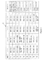
図3を参照すると、番号列16は、間隔T1、T2…T9に分割された1つの事象の間で各センサ(センサ1〜4が示されている)毎に、読取り値の取り扱いを示す。間隔T1〜T9は、一例にすぎない。これによりさらに少ないかまたは多くの間隔を利用することもできる。アルゴリズムが一旦間隔T1〜T9で実行されると、このアルゴリズムを再び繰り返すことができる。実施例においては、各間隔T1〜T9はおよそ60秒であるが、それ以外の間隔を利用することもできる。
Referring to FIG. 3, the
時刻T1で、事象は始まる。時刻T3は、センサ1および2が放出された物質による影響を受け始める最初の時刻である。センサラグに起因して、濃度読取りを得るために、例えば60秒というさらなる時間がかかることがある。時刻T4で、センサ1および2は実際の濃度読取り値を得る。アルゴリズム14は、間隔T4で行われた実際の濃度読取りに関係するセンサ1および2の双方について間隔T3に関する濃度値を、記入する。実施例においては、アルゴリズムは、間隔T4内でセンサ1および2について読取られた濃度読取り値と同じである、間隔T3における濃度読取り値を、記入する。間隔T7では、センサ2は、センサ2の計器タイプについて最大読取り値である読取り値を得る。これは、センサ2の飽和を表すので不正確であるから間隔T7以降はセンサ2からの読取り値は使用されない。しかしながら、センサ1は間隔T9を超えても有効な読取り値を得続ける。間隔T8で、センサ4は読取り値を得始めるが、信頼性の高い読取り値は得られない。しかし、間隔T9では、センサ4は、たとえ間隔T8で信頼性の高い読取り値を得ることができなかったとしても、その間隔T8で発生したとアルゴリズム14が仮定する有効な読取り値を得る。有効な読取り値が時間的に遡って予想される間隔は、センサの物理的特性の関数であり、この間隔は読取り値の獲得と信頼性の高い読取り値の獲得との間のタイムラグによって設定される。間隔T9内では、センサ3は読取り値を取得し始めるが、それはまだ高い信頼性のものではない。
At time T1, the event begins. Time T3 is the first time at which
列16内の読取り値の扱い方法は、図3中の右側の欄に示されている。間隔T3〜T6にて、物質推定放出の計算のためにセンサ1および2が使用される。間隔T7では、センサ1が放出レート計算のために使用された。間隔T8〜T9にて、アルゴリズム14内での計算のために、センサ1および4が使用された。この技術は、有効な測定範囲に基づいて参加可能なできるだけ沢山のセンサに対して使用することができる。プログラムは、放出が停止するまで、事象が継続する間は何度でも、実行させることができる。放出がひとたび停止させられると、アルゴリズムは、以下でさらに詳述する数学的収束を得るために濃度を監視し続け、プルームを以下に規定されている予想濃度と比較する。
The way of handling the readings in
アルゴリズム14は、実施例においては、放出レートについての推測されたまたは仮定されたまたは予測されたまたは試みの値をもって、拡散モデル(dispersion model)を実行する。アルゴリズム14は、各センサについて、時刻プロフィール18を生成する(図4(a)〜(c))。実際のセンサ情報すなわちセンサ時刻および濃度測定値は、予測プロフィールに合致させられる。特定の収束期間20内に合致が存在するか否かの決定が行われる。全てのセンサについて、時間および濃度測定値に関する合致がその収束期間内に存在する場合、予測値は、真の値として記録される。そうでなければ、新たな予測プロフィールが試みられる。実際の濃度値がライン22によって表されている。実際の時刻値がライン24により表されている。収束については2つのループが存在する。1つのループは、時刻パラメータ上で収束し、もう1つは濃度パラメータ上で収束する。時刻および濃度パラメータの両方が許容誤差限界内で収束する場合、計算値は受入れられる。
The
その試みの方法は基本的に、放出レートまたは量について限界を設定することになり、その後、実際の放出レートまたは放出量を求めるために、二分ニュートン・ラプソン法(Bisection Newton−Raphson)、挟み撃ち法(talse position)等の求根方法のうちの1つを使用することになる。この手順が完了した後、放出源Sについての「放出レート対時間」が得られ、これは次に化学的影響についての、拡散モデルに与えられる。この手順は、新しい情報が受信される都度繰り返され、更新が決定される。プルームの中心線C(図2)により近いところで取られた測定値ほどおよび放出点Sに近過ぎず遠過ぎない読取り値ほど、精度はより高くなる。 The attempted method would basically set a limit on the release rate or quantity, and then to determine the actual release rate or quantity, the Bisection Newton-Raphson method, pinching method One of the root finding methods such as (talse position) will be used. After this procedure is complete, an “emission rate versus time” for the emission source S is obtained, which is then given to the diffusion model for chemical effects. This procedure is repeated each time new information is received, and an update is determined. The measurements taken closer to the plume centerline C (FIG. 2) and the readings not too close and not too far from the emission point S are more accurate.
アルゴリズムを早めるためには、重み係数を適用することができる。この重み係数の値は、プルーム中心線でとられた測定値から、雲の縁部での測定値まで、例えば0.1だけ変化させることができる。したがって中心線濃度の精度について1%の許容誤差が設定されている場合、縁部測定値は10%の精度しか必要としない。これは、各センサに対し重み係数をその位置の関数として割当てることによって達成可能である。反復中、これらの重み係数は、各センサについて収束基準を決定するのに使用できる。 To speed up the algorithm, a weighting factor can be applied. The value of this weighting factor can be varied, for example, by 0.1 from the measured value taken at the plume centerline to the measured value at the edge of the cloud. Therefore, if a tolerance of 1% is set for the accuracy of the centerline density, the edge measurement requires only 10% accuracy. This can be achieved by assigning each sensor a weighting factor as a function of its position. During the iteration, these weighting factors can be used to determine the convergence criterion for each sensor.
その収束基準は、以下の通りとすることができる: Its convergence criteria can be as follows:

なお式中、Cmeas=測定濃度
Cest=推定濃度
TOL=許容誤差
Wn=各センサについての重み係数でこのWnは0.1〜1の間にある
各センサについての上記式(1)中の基準を満たした後、プログラムは完了し、放出レートを報告することになる。
In the formula, Cmeas = measured concentration
Cest = estimated concentration TOL = allowable error Wn = weighting factor for each sensor and Wn is between 0.1 and 1 The program is complete after satisfying the criteria in equation (1) above for each sensor The release rate will be reported.
アルゴリズム14は、気象データ(26)および種々のセンサからのセンサデータ(28)を得ることによって開始する。気象データは、気象センサ27から得ることができる。あるいは、気象データは、インターネットといった広域電子ネットワーク、政府ダイアルアップサービス、その他の会社の固定システム、無線携帯式気象センサから得ることができ、又気象専門家等がそれを推定することもできる。30では、アルゴリズムは、検出中の化学物質を決定する。化学物質が、何かを検出しているセンサのタイプに対応するものと想定する。換言すると、特定の化学物質のためのセンサがある条件を検知している場合に、有毒性放出の源がその化学物質であると想定する。アルゴリズム14は、その結論が後に正しくないと決定された場合、それを変更することができる。
The
32で、アルゴリズムはセンサのうちの1つを選択し、34では1つの試みを行うかまたは予測された放出レートを選択する。拡散分析が36で実行され、38では収束したか否かが決定される。38で収束しなかったと決定された場合には、新しい予測放出レートが34で選ばれ、38で収束したことが決定されるまで、36で拡散分析が繰り返される。38で収束したと決定された場合、放出レートおよびそれに伴う時間は40で記録される。42で、全てのセンサ12がこの要領で処理されたものと決定された場合、全てのセンサについての放出レート計算は44で評価される。これは、図3に示された測定時刻と共に、各々の測定濃度についての逆算モデルにより放出レートを推定することによって、達成することができる。各時刻における各濃度についての調整が、放出源から測定場所までの雲の移動時間を考慮に入れるために行われる。これらの時刻印付きのレートは時間的に昇順に選別されてから、プルームの全体的な影響についての拡散モデルに移行させられる。放出が始まる時刻から最も早くに記録された時刻についての推定レートが使用されることになる。同じ時刻でそれぞれ計算されたレートについて、算術的平均放出レートを使用することが可能である。センサからの放出レート読取り値が、有効な放出レート読取り値と一貫性のあるものである場合、公知の統計的プロセスを利用してこれら読取り値が結合され、モニター等の上に放出レートの影響が表示される(46)。
At 32, the algorithm selects one of the sensors, and at 34, makes one attempt or selects the predicted release rate. A diffusion analysis is performed at 36 and at 38 it is determined whether it has converged. If it is determined at 38 that it has not converged, a new predicted release rate is selected at 34 and the diffusion analysis is repeated at 36 until it is determined at 38 that it has converged. If it is determined that it has converged at 38, the release rate and the associated time are recorded at 40. If it is determined at 42 that all
物質放出推定システム10は、事象が発生したときに放出される有毒化学物質の量の推定を可能にする。さらに、該システムは、分析からオペレータの技量をとり除いてきわめて自動化されたものとなる。さらに、1つの事象の発生をオペレータに警告するのに利用できるように、測定における1つの因子として時刻を考慮に入れることにより、該物質放出推定システムを監視システムとして使用することができる。実施例においては、携帯式センサ12Pは、Rae Systemsによって製造されているタイプのもの、Gastoronicsにより製造された無線ガス検出システムまたはその他の市販の無線ガス検出システムでよい。物質放出推定システム10を利用すると、データが変わるにつれて結果が更新される。10分間といった間隔の間、データは自動的に更新される。より一層多くのデータが得られるほど、プルームを連続的に再生成することができる。
Substance
物質放出推定システム10は、当事者による事象の後での再検討のために、その事象の記録を作成することができる。特に固定センサが設置されている設備を監視するために該システムを利用することが可能である。プルームの移動が予想される風下の場所には、携帯式センサを設置することができる。プルームの移動の監視は、物質放出推定システム10によって可能であるように、大気条件の自動入力によって支援される。本発明は、当該技術分野において既知のあらゆる既存の拡散モデリングで好適に作用する。これには、当該譲受人SAFER Systems, L. L. C.から市販されているREAL−TIMETMシステム、米国政府により供給されているALOHAシステム、Radiant Corporationにより供給されているCHARMシステム、Brank Software Systemsにより供給されているCOMPASシステム等を含みうる。かかる拡散モデルは、放出場所のまわりの物質バランスに基づいているが、その他の拡散モデルベースを使用することもできる。
The substance
物質放出推定システムは、a)ガス検出センサ、b)気象学的測定、c)放出位置情報、d)放出開始時刻およびe)拡散モデルを利用している。システム10で有用なセンサタイプの例としては、PID、電気化学物質、紙テープ、オープンパスなどが含まれる。センサの場所は、広域位置情報で測定されるかまたは口頭で表しうる。測定時刻ならびに濃度測定値の上限および下限が、対応すべき化学物質またはどの物質を正確に測定可能か等ということと共に、考慮される。気象学的測定には、風速および風向、ならびに環境保護局(EPA)によって規定されるような安定的分類を含みうる。放出場所は、実際の放出源である。
The substance release estimation system uses a) gas detection sensor, b) meteorological measurement, c) release position information, d) release start time, and e) diffusion model. Examples of sensor types useful in the
物質放出推定システム10は、自立型システムであってもよいし、又その他のプログラムの中に組み入れられてもよい。前述のように、システム10は拡散モデリングのために利用でき、事象の展開、事後の事象の展開の再構築、および放出の発生に関する機器の監視、に対する補助をなす。有毒性液体または気体化学物質についての使用について記述したが、該物質放出推定システム10はまた、非毒性化学物質放出を追跡するためにも使用可能である。
The substance
具体的に記述された実施形態における変更および修正を、均等論を含む特許法の原則に従って解釈される通り添付のクレームの範囲によってのみ規定されるように意図された本発明の原理から逸脱することなく、行うことができる。 Changes and modifications in the specifically described embodiments depart from the principles of the invention which are intended to be defined only by the scope of the appended claims as interpreted in accordance with the principles of patent law, including doctrine of equivalents. Can be done.
Claims (10)
多数の場所のうちの各々で、少なくとも1つのセンサを介して、かつ多数の時刻に前記物質の実際の濃度測定を多数回行う段階と、
前記場所の各々における前記多数の実際の測定濃度および前記測定時刻の関数として、放出された前記物質の放出レートを推定する段階と、
からなり、
前記の推定する段階は、試みの放出レートに基づいて予測時刻での予測濃度を提供する段階と、前記実際の測定濃度および時刻と、前記予測濃度および時刻とを比較する段階を含むと共に、該推定する段階はさらに、該比較の結果に応じて前記の試みの放出レートを修正して該修正された試みの放出レートに基づく予測濃度および時刻をもって、前記実際の測定濃度および時刻が許容誤差限界内に収束したことを決定する段階とを含む方法。In a method for estimating the amount of a substance released into the surrounding medium and thus creating a plume,
Performing multiple measurements of the actual concentration of the substance at each of a number of locations via at least one sensor and at a number of times;
Estimating the release rate of the released substance as a function of the multiple actual measured concentrations and the measurement time at each of the locations;
Consists of
The estimating includes providing a predicted concentration at a predicted time based on an attempted release rate, comparing the actual measured concentration and time with the predicted concentration and time, and The step of estimating further modifies the release rate of the attempt according to the result of the comparison, so that the actual measured concentration and time are within the tolerance limits with a predicted concentration and time based on the revised release rate of the attempt. Determining that it has converged within .
多数の場所のうちの各々で、少なくとも1つのセンサを介して、かつ多数の時刻に前記物質の実際の濃度測定を多数回行う段階と、
前記場所の各々における前記多数の実際の測定濃度および前記測定時刻の関数として、放出された前記物質の量を推定する段階と、
からなり、
前記の推定する段階は、試みの放出レートに基づいて予測時刻での予測濃度を提供する段階と、前記実際の測定濃度および時刻と、前記予測濃度および時刻とを比較する段階を含むと共に、該推定する段階はさらに、該比較の結果に応じて前記の試みの放出レートを修正して該修正された試みの放出レートに基づく予測濃度および時刻をもって、前記実際の測定濃度および時刻が許容誤差限界内に収束したことを決定する段階とを含み、
前記の推定する段階は、前記プルームの移動時間についての前記の測定を調整する段階を含む方法。In a method for estimating the amount of a substance released into the surrounding medium and thus creating a plume,
Making multiple measurements of the actual concentration of said substance at each of a number of locations via at least one sensor and at a number of times;
Estimating the amount of the substance released as a function of the multiple actual measured concentrations and the measurement time at each of the locations;
Consists of
The estimating includes providing a predicted concentration at a predicted time based on an attempted release rate, comparing the actual measured concentration and time with the predicted concentration and time, and The step of estimating further modifies the release rate of the attempt according to the result of the comparison, so that the actual measured concentration and time are within the tolerance limits with a predicted concentration and time based on the revised release rate of the attempt. Determining that it has converged within ,
The estimating step includes adjusting the measurement of the plume travel time.
前記プルームに位置付けされて前記放出された物質の実際の濃度を測定する少なくとも1つのセンサと、
前記物質が中に放出される周囲媒質の大気条件を入力するような大気条件入力部と、
アルゴリズムでプログラミングされ、多数の時刻に前記少なくとも1つのセンサからの多数の実際の濃度測定値を受信し、前記大気条件入力部から大気条件を受信するコンピュータベースの分析装置であって、前記アルゴリズムが前記濃度測定値および前記大気条件から、物質放出レートの推定値を生成する分析装置と、
を含んでなり、
前記の推定においては、試みの放出レートに基づく予測時刻での予測濃度と、前記実際の測定濃度および時刻と前記予測濃度および時刻とを比較するアルゴリズムとを含むと共に、該アルゴリズムはさらに、該比較の結果に応じて前記の試みの放出レートを修正し、この修正された試みの放出レートに基づく予測濃度および時刻をもって、前記実際の測定濃度および時刻が許容誤差限界内に収束したことを決定するシステム。In a substance release rate estimation system for estimating the amount of substance released from the plume created by the release,
At least one sensor positioned in the plume and measuring an actual concentration of the released substance;
An atmospheric condition input unit for inputting atmospheric conditions of an ambient medium into which the substance is released;
A computer-based analyzer that is programmed with an algorithm, receives a number of actual concentration measurements from the at least one sensor at a number of times, and receives atmospheric conditions from the atmospheric condition input, the algorithm comprising: An analyzer that generates an estimate of the substance release rate from the concentration measurement and the atmospheric conditions;
Comprising
The estimation includes a predicted concentration at a predicted time based on an attempted release rate, and an algorithm that compares the actual measured concentration and time to the predicted concentration and time, the algorithm further comprising the comparison The release rate of the attempt is corrected according to the result of the step, and with the predicted concentration and time based on the release rate of the corrected attempt, it is determined that the actual measured concentration and time have converged within tolerance limits. system.
プルームに対して異なる多数の場所に位置付けされて多数の時刻に異なる場所で放出された物質の実際の濃度測定を多数回行うような複数のセンサと、
アルゴリズムでプログラミングされ、前記複数のセンサからの実際の濃度測定値を受信するコンピュータベースの分析装置であって、前記アルゴリズムが前記濃度測定値から、放出された前記物質の放出レートの推定値を生成する分析装置と、
を含んでなり、
前記の推定においては、試みの放出レートに基づく予測時刻での予測濃度と、前記実際の測定濃度および時刻と前記予測濃度および時刻とを比較するアルゴリズムとを含むと共に、該アルゴリズムはさらに、該比較の結果に応じて前記の試みの放出レートを修正し、この修正された試みの放出レートに基づく予測濃度および時刻をもって、前記実際の測定濃度および時刻が許容誤差限界内に収束したことを決定するシステム。In a system for estimating the amount of material released, wherein the release creates a plume,
A plurality of sensors that are positioned at a number of different locations relative to the plume and that make multiple measurements of the actual concentration of substances released at different times at a number of times;
A computer-based analyzer that is programmed with an algorithm and receives actual concentration measurements from the plurality of sensors, wherein the algorithm generates an estimate of the released rate of the released substance from the concentration measurement An analyzing device,
Comprising
The estimation includes a predicted concentration at a predicted time based on an attempted release rate, and an algorithm that compares the actual measured concentration and time to the predicted concentration and time, the algorithm further comprising the comparison The release rate of the attempt is modified according to the result of the step, and with the predicted concentration and time based on the modified attempt release rate, it is determined that the actual measured concentration and time have converged within tolerance limits. system.
プルームに位置づけされ多数の時刻において放出された物質の実際の濃度測定を多数回行うような少なくとも1つのセンサと、アルゴリズムでプログラミングされ、前記の少なくとも1つのセンサからの実際の濃度測定値を受信するコンピュータベースの分析装置であって、前記アルゴリズムが前記実際の濃度測定値から、放出された前記物質の量の推定値を生成する分析装置と、
を含んでなるシステムであって、
多数回の実際の測定が、異なる多数の場所の各々で行われ、放出された物質の量が、前記場所の各々における前記多数の実際の濃度測定値および前記測定時刻の関数として推定され、
前記の推定においては、試みの放出レートに基づく予測時刻での予測濃度を含み、前記アルゴリズムは前記実際の測定濃度および時刻と前記予測濃度および時刻とを比較し、該アルゴリズムはさらに、該比較の結果に応じて前記の試みの放出レートを修正し、この修正された試みの放出レートに基づく予測濃度および時刻をもって、前記実際の測定濃度および時刻が許容誤差限界内に収束したことを決定し、
そして前記推定値が、前記プルームの移動時刻について調整される、
システム。A system for estimating the amount of substance released, a substance release estimation system in which a plume is created by the release;
At least one sensor, which is positioned in the plume and performs a number of actual measurements of the substance released at a number of times, and is programmed with an algorithm and receives the actual concentration measurements from said at least one sensor A computer-based analyzer, wherein the algorithm generates an estimate of the amount of the substance released from the actual concentration measurement;
A system comprising:
A number of actual measurements are made at each of a number of different locations, and the amount of material released is estimated as a function of the number of actual concentration measurements at each of the locations and the measurement time,
The estimation includes a predicted concentration at a predicted time based on an attempted release rate, the algorithm compares the actual measured concentration and time to the predicted concentration and time, and the algorithm further includes the comparison Modify the release rate of the trial according to the results, and with the predicted concentration and time based on the revised trial release rate, determine that the actual measured concentration and time have converged within acceptable error limits ;
And the estimated value is adjusted for the movement time of the plume,
system.
Applications Claiming Priority (4)
| Application Number | Priority Date | Filing Date | Title |
|---|---|---|---|
| US28475001P | 2001-04-18 | 2001-04-18 | |
| US31242901P | 2001-08-15 | 2001-08-15 | |
| US10/098,685 US6772071B2 (en) | 2001-04-18 | 2002-03-15 | Estimation of toxic substance release |
| PCT/US2002/012147 WO2002086547A1 (en) | 2001-04-18 | 2002-04-18 | Estimation of toxic substance release |
Publications (3)
| Publication Number | Publication Date |
|---|---|
| JP2004528562A JP2004528562A (en) | 2004-09-16 |
| JP2004528562A5 JP2004528562A5 (en) | 2005-12-22 |
| JP4515708B2 true JP4515708B2 (en) | 2010-08-04 |
Family
ID=27378641
Family Applications (1)
| Application Number | Title | Priority Date | Filing Date |
|---|---|---|---|
| JP2002584019A Expired - Lifetime JP4515708B2 (en) | 2001-04-18 | 2002-04-18 | Estimate of toxic substance release |
Country Status (7)
| Country | Link |
|---|---|
| US (1) | US6772071B2 (en) |
| EP (1) | EP1393099B1 (en) |
| JP (1) | JP4515708B2 (en) |
| AT (1) | ATE537444T1 (en) |
| CA (1) | CA2444072C (en) |
| MX (1) | MXPA03009556A (en) |
| WO (1) | WO2002086547A1 (en) |
Families Citing this family (29)
| Publication number | Priority date | Publication date | Assignee | Title |
|---|---|---|---|---|
| US7064660B2 (en) * | 2002-05-14 | 2006-06-20 | Motorola, Inc. | System and method for inferring an electronic rendering of an environment |
| US7834754B2 (en) | 2002-07-19 | 2010-11-16 | Ut-Battelle, Llc | Method and system for monitoring environmental conditions |
| WO2005017659A2 (en) * | 2003-07-02 | 2005-02-24 | The United States Of America, As Represented By The Secretary Of The Navy | Software system for zero emergency assessment of airborn, chemical, biological, radiological (cbr) threats |
| CA2476902C (en) * | 2003-08-20 | 2014-04-22 | Dennis S. Prince | Innovative gas monitoring with spacial and temporal analysis |
| US8949037B2 (en) * | 2003-08-20 | 2015-02-03 | Airdar Inc. | Method and system for detecting and monitoring emissions |
| SE0401607D0 (en) * | 2004-06-22 | 2004-06-22 | Nilsson Intelligence Systems A | Monitoring system |
| US8712335B2 (en) * | 2005-12-30 | 2014-04-29 | Honeywell International Inc. | Wireless monitoring in process applications |
| US10368146B2 (en) | 2016-09-20 | 2019-07-30 | General Electric Company | Systems and methods for environment sensing |
| US8145439B2 (en) * | 2007-08-06 | 2012-03-27 | Safer Systems, L.L.C. | Substance release estimation using path-averaged concentration measurements |
| US8190376B2 (en) * | 2008-08-18 | 2012-05-29 | Safer Systems, Llc | System and method for source identification for a chemical release |
| US20100148946A1 (en) * | 2008-12-16 | 2010-06-17 | Portendo Ab | Surveillance System |
| EP2419766B1 (en) * | 2009-04-14 | 2022-06-29 | Airdar Inc. | System for measuring emission and quantifying emission source |
| US9978251B2 (en) * | 2009-12-28 | 2018-05-22 | Honeywell International Inc. | Wireless location-based system and method for detecting hazardous and non-hazardous conditions |
| US9229132B2 (en) | 2011-07-05 | 2016-01-05 | International Business Machines Corporation | Meteorological parameter forecasting |
| US9294936B2 (en) | 2012-08-14 | 2016-03-22 | Honeywell International Inc. | System and method for improved location system accuracy |
| US9595183B2 (en) * | 2014-04-25 | 2017-03-14 | Safer Systems, Llc | System and method for distribution of sensors for emergency response |
| WO2016141582A1 (en) * | 2015-03-12 | 2016-09-15 | Honeywell International Inc. | Wireless mesh network gas detection real time location system |
| US10156552B2 (en) | 2015-05-13 | 2018-12-18 | Honeywell International Inc. | Method to auto-configure gas detectors based on real-time location |
| CA2977392A1 (en) * | 2016-09-09 | 2018-03-09 | Delta M Incorporated | System and method of testing for airborne pathogens, toxins, pollutants and/or contaminants |
| CA3079192C (en) | 2016-10-18 | 2021-07-27 | The Regents Of The Unversity Of Colorado, A Body Corporate | Apparatus and methods for location and sizing of trace gas sources |
| US10775258B2 (en) * | 2018-03-13 | 2020-09-15 | International Business Machines Corporation | Heuristic based analytics for gas leak source identification |
| CN110726805B (en) * | 2019-09-29 | 2021-03-05 | 中国农业大学 | Oxygen leakage early warning device and oxygen leakage early warning method in aquarium fish transportation |
| US11636870B2 (en) | 2020-08-20 | 2023-04-25 | Denso International America, Inc. | Smoking cessation systems and methods |
| US11760169B2 (en) | 2020-08-20 | 2023-09-19 | Denso International America, Inc. | Particulate control systems and methods for olfaction sensors |
| US11932080B2 (en) | 2020-08-20 | 2024-03-19 | Denso International America, Inc. | Diagnostic and recirculation control systems and methods |
| US11813926B2 (en) | 2020-08-20 | 2023-11-14 | Denso International America, Inc. | Binding agent and olfaction sensor |
| US11760170B2 (en) | 2020-08-20 | 2023-09-19 | Denso International America, Inc. | Olfaction sensor preservation systems and methods |
| US11828210B2 (en) | 2020-08-20 | 2023-11-28 | Denso International America, Inc. | Diagnostic systems and methods of vehicles using olfaction |
| US11881093B2 (en) | 2020-08-20 | 2024-01-23 | Denso International America, Inc. | Systems and methods for identifying smoking in vehicles |
Family Cites Families (17)
| Publication number | Priority date | Publication date | Assignee | Title |
|---|---|---|---|---|
| FR2542453B1 (en) * | 1983-03-07 | 1985-07-12 | Centre Electron Horloger | MINIATURE MAGNETIC FIELD DEVICE AND MAGNETIC FIELD MEASURING APPARATUS INCLUDING SUCH A DEVICE |
| US4924095A (en) | 1987-06-02 | 1990-05-08 | West Lodge Research | Remote gas analyzer for motor vehicle exhaust emissions surveillance |
| US5057227A (en) * | 1990-10-09 | 1991-10-15 | University Of South Carolina | Method for in-situ removal of hydrocarbon contaminants from groundwater |
| US5132968A (en) | 1991-01-14 | 1992-07-21 | Robotic Guard Systems, Inc. | Environmental sensor data acquisition system |
| US5297421A (en) | 1991-03-05 | 1994-03-29 | Mitsui Toatsu Chemicals, Inc. | Leak detection system for gas, steam or the like that involves multi-point sampling |
| JPH07198523A (en) * | 1993-12-28 | 1995-08-01 | Chiyoda Corp | Estimation method for gas leakage point and amount based on gas concentration and wind speed data |
| US5468964A (en) * | 1994-06-20 | 1995-11-21 | The University Of Chicago | Millimeter wave sensor for monitoring effluents |
| US5604299A (en) | 1995-05-26 | 1997-02-18 | Sensible Technologies, Inc. | Method of locating emission sources |
| US5807113A (en) * | 1996-04-22 | 1998-09-15 | The United States Of America As Represented By The Secretary Of The Army | Method and apparatus for training in the detection of nuclear, biological and chemical (NBC) contamination |
| US5739686A (en) * | 1996-04-30 | 1998-04-14 | Naughton; Michael J. | Electrically insulating cantilever magnetometer with mutually isolated and integrated thermometry, background elimination and null detection |
| US5724255A (en) * | 1996-08-27 | 1998-03-03 | The University Of Wyoming Research Corporation | Portable emergency action system for chemical releases |
| US5832411A (en) | 1997-02-06 | 1998-11-03 | Raytheon Company | Automated network of sensor units for real-time monitoring of compounds in a fluid over a distributed area |
| DE69841173D1 (en) * | 1997-04-18 | 2009-11-05 | Goodrich Corp | METHOD AND DEVICE FOR REMOTE CONCENTRATION MEASUREMENT OF GASPURES |
| DE19823599A1 (en) | 1998-05-27 | 1999-12-09 | Beb Erdgas & Erdoel Gmbh | Methods and devices for monitoring plants in the chemical industry |
| US6252510B1 (en) | 1998-10-14 | 2001-06-26 | Bud Dungan | Apparatus and method for wireless gas monitoring |
| DE19858022C2 (en) | 1998-12-16 | 2002-11-28 | Draeger Safety Ag & Co Kgaa | Procedure for measuring gas concentrations |
| JP2001042052A (en) * | 1999-07-30 | 2001-02-16 | Weather Information System Co Ltd | Regional environment monitoring system for chemical substance such as dioxins, particulate falling object and the like |
-
2002
- 2002-03-15 US US10/098,685 patent/US6772071B2/en not_active Expired - Lifetime
- 2002-04-18 JP JP2002584019A patent/JP4515708B2/en not_active Expired - Lifetime
- 2002-04-18 CA CA002444072A patent/CA2444072C/en not_active Expired - Lifetime
- 2002-04-18 MX MXPA03009556A patent/MXPA03009556A/en active IP Right Grant
- 2002-04-18 AT AT02723887T patent/ATE537444T1/en active
- 2002-04-18 WO PCT/US2002/012147 patent/WO2002086547A1/en active Application Filing
- 2002-04-18 EP EP02723887A patent/EP1393099B1/en not_active Expired - Lifetime
Also Published As
| Publication number | Publication date |
|---|---|
| WO2002086547A1 (en) | 2002-10-31 |
| ATE537444T1 (en) | 2011-12-15 |
| US20020169557A1 (en) | 2002-11-14 |
| EP1393099A4 (en) | 2006-10-11 |
| CA2444072C (en) | 2009-12-22 |
| CA2444072A1 (en) | 2002-10-31 |
| JP2004528562A (en) | 2004-09-16 |
| US6772071B2 (en) | 2004-08-03 |
| MXPA03009556A (en) | 2004-12-06 |
| EP1393099B1 (en) | 2011-12-14 |
| EP1393099A1 (en) | 2004-03-03 |
Similar Documents
| Publication | Publication Date | Title |
|---|---|---|
| JP4515708B2 (en) | Estimate of toxic substance release | |
| US11131639B2 (en) | Analyzer, analysis system, analysis method and program | |
| US5970426A (en) | Emission monitoring system | |
| JP2019527344A (en) | Method and apparatus for detection, and method and apparatus for improving detection accuracy | |
| JP2008267992A (en) | Leak detection system | |
| JP2004528562A5 (en) | ||
| CN113777236B (en) | Air quality monitoring method and device based on emission source | |
| US11378485B2 (en) | Structural monitoring system | |
| US20220260543A1 (en) | Real-time atmospheric diffusion monitoring system | |
| US20220260539A1 (en) | Integrated monitoring system for real-time odor tracking | |
| US20190033160A1 (en) | Adaptive sensing for gas leak detection | |
| KR20070060221A (en) | System for real-time monitoring odor and method thereof | |
| Badicu et al. | PMs concentration forecasting using ARIMA algorithm | |
| US6539311B1 (en) | Apparatus and method for measuring concentrations of a chemical/biological/nuclear agent in an environment | |
| KR100851520B1 (en) | Apparatus and method for inferring atmosphere environment of underground space using statistical analysis | |
| Halama et al. | Prediction of atmospheric corrosion of carbon steel using artificial neural network model in local geographical regions | |
| KR102266838B1 (en) | Monitoring technique for leaching water of burial sites using field sensors and machine learning | |
| CN117114505B (en) | Building construction site environment monitoring method and system | |
| JP7180946B2 (en) | Earthquake information processing equipment | |
| Andria et al. | Model characterization in measurements of environmental pollutants via data correlation of sensor outputs | |
| Squire et al. | Inter-organisational sampling trials for the uncertainty estimation of landfill gas measurements | |
| JP2014106203A (en) | Diffusate diffusion state prediction device, method of the same and program | |
| EP3751209A1 (en) | A computer implemented method, a computer program, and a system for monitoring refrigerant gas leaks in a refrigeration system | |
| JP2006047171A (en) | Method, device, and system for evaluating amount of contamination | |
| KR20050122623A (en) | Potable airwatch system |
Legal Events
| Date | Code | Title | Description |
|---|---|---|---|
| A521 | Request for written amendment filed |
Free format text: JAPANESE INTERMEDIATE CODE: A523 Effective date: 20050415 |
|
| A621 | Written request for application examination |
Free format text: JAPANESE INTERMEDIATE CODE: A621 Effective date: 20050415 |
|
| A131 | Notification of reasons for refusal |
Free format text: JAPANESE INTERMEDIATE CODE: A131 Effective date: 20080415 |
|
| A601 | Written request for extension of time |
Free format text: JAPANESE INTERMEDIATE CODE: A601 Effective date: 20080714 |
|
| A602 | Written permission of extension of time |
Free format text: JAPANESE INTERMEDIATE CODE: A602 Effective date: 20080722 |
|
| A521 | Request for written amendment filed |
Free format text: JAPANESE INTERMEDIATE CODE: A523 Effective date: 20081002 |
|
| A131 | Notification of reasons for refusal |
Free format text: JAPANESE INTERMEDIATE CODE: A131 Effective date: 20090707 |
|
| A601 | Written request for extension of time |
Free format text: JAPANESE INTERMEDIATE CODE: A601 Effective date: 20091006 |
|
| A602 | Written permission of extension of time |
Free format text: JAPANESE INTERMEDIATE CODE: A602 Effective date: 20091014 |
|
| A521 | Request for written amendment filed |
Free format text: JAPANESE INTERMEDIATE CODE: A523 Effective date: 20091120 |
|
| TRDD | Decision of grant or rejection written | ||
| A01 | Written decision to grant a patent or to grant a registration (utility model) |
Free format text: JAPANESE INTERMEDIATE CODE: A01 Effective date: 20100413 |
|
| A01 | Written decision to grant a patent or to grant a registration (utility model) |
Free format text: JAPANESE INTERMEDIATE CODE: A01 |
|
| A61 | First payment of annual fees (during grant procedure) |
Free format text: JAPANESE INTERMEDIATE CODE: A61 Effective date: 20100513 |
|
| R150 | Certificate of patent or registration of utility model |
Ref document number: 4515708 Country of ref document: JP Free format text: JAPANESE INTERMEDIATE CODE: R150 Free format text: JAPANESE INTERMEDIATE CODE: R150 |
|
| FPAY | Renewal fee payment (event date is renewal date of database) |
Free format text: PAYMENT UNTIL: 20130521 Year of fee payment: 3 |
|
| R250 | Receipt of annual fees |
Free format text: JAPANESE INTERMEDIATE CODE: R250 |
|
| R250 | Receipt of annual fees |
Free format text: JAPANESE INTERMEDIATE CODE: R250 |
|
| R250 | Receipt of annual fees |
Free format text: JAPANESE INTERMEDIATE CODE: R250 |
|
| R250 | Receipt of annual fees |
Free format text: JAPANESE INTERMEDIATE CODE: R250 |
|
| R250 | Receipt of annual fees |
Free format text: JAPANESE INTERMEDIATE CODE: R250 |
|
| R250 | Receipt of annual fees |
Free format text: JAPANESE INTERMEDIATE CODE: R250 |
|
| R250 | Receipt of annual fees |
Free format text: JAPANESE INTERMEDIATE CODE: R250 |
|
| R250 | Receipt of annual fees |
Free format text: JAPANESE INTERMEDIATE CODE: R250 |
|
| R250 | Receipt of annual fees |
Free format text: JAPANESE INTERMEDIATE CODE: R250 |
|
| EXPY | Cancellation because of completion of term |