JP4515319B2 - Computer system - Google Patents
Computer system Download PDFInfo
- Publication number
- JP4515319B2 JP4515319B2 JP2005129182A JP2005129182A JP4515319B2 JP 4515319 B2 JP4515319 B2 JP 4515319B2 JP 2005129182 A JP2005129182 A JP 2005129182A JP 2005129182 A JP2005129182 A JP 2005129182A JP 4515319 B2 JP4515319 B2 JP 4515319B2
- Authority
- JP
- Japan
- Prior art keywords
- content
- server
- hash value
- client terminal
- url
- Prior art date
- Legal status (The legal status is an assumption and is not a legal conclusion. Google has not performed a legal analysis and makes no representation as to the accuracy of the status listed.)
- Expired - Fee Related
Links
Images


Classifications
-
- H—ELECTRICITY
- H04—ELECTRIC COMMUNICATION TECHNIQUE
- H04L—TRANSMISSION OF DIGITAL INFORMATION, e.g. TELEGRAPHIC COMMUNICATION
- H04L67/00—Network arrangements or protocols for supporting network services or applications
- H04L67/01—Protocols
- H04L67/10—Protocols in which an application is distributed across nodes in the network
- H04L67/1001—Protocols in which an application is distributed across nodes in the network for accessing one among a plurality of replicated servers
- H04L67/1004—Server selection for load balancing
- H04L67/1021—Server selection for load balancing based on client or server locations
-
- H—ELECTRICITY
- H04—ELECTRIC COMMUNICATION TECHNIQUE
- H04L—TRANSMISSION OF DIGITAL INFORMATION, e.g. TELEGRAPHIC COMMUNICATION
- H04L67/00—Network arrangements or protocols for supporting network services or applications
- H04L67/01—Protocols
- H04L67/10—Protocols in which an application is distributed across nodes in the network
- H04L67/1001—Protocols in which an application is distributed across nodes in the network for accessing one among a plurality of replicated servers
- H04L67/1004—Server selection for load balancing
- H04L67/1023—Server selection for load balancing based on a hash applied to IP addresses or costs
-
- H—ELECTRICITY
- H04—ELECTRIC COMMUNICATION TECHNIQUE
- H04L—TRANSMISSION OF DIGITAL INFORMATION, e.g. TELEGRAPHIC COMMUNICATION
- H04L67/00—Network arrangements or protocols for supporting network services or applications
- H04L67/50—Network services
- H04L67/60—Scheduling or organising the servicing of application requests, e.g. requests for application data transmissions using the analysis and optimisation of the required network resources
- H04L67/63—Routing a service request depending on the request content or context
-
- H—ELECTRICITY
- H04—ELECTRIC COMMUNICATION TECHNIQUE
- H04L—TRANSMISSION OF DIGITAL INFORMATION, e.g. TELEGRAPHIC COMMUNICATION
- H04L67/00—Network arrangements or protocols for supporting network services or applications
- H04L67/50—Network services
- H04L67/60—Scheduling or organising the servicing of application requests, e.g. requests for application data transmissions using the analysis and optimisation of the required network resources
Description
本発明は、パケット転送装置を備えるコンピュータシステムに関し、特に、URLスイッチを用いた転送制御に関する。 The present invention relates to a computer system including a packet transfer apparatus, and more particularly to transfer control using a URL switch.
インターネット上で提供される各種サービスは、ストリーム型の通信プロトコルであるTCP上で実現されることが多い(非特許文献1参照)。例えば、World-Wide Webは、TCP上のプロトコルであるHypertext Transport Protocol(HTTP、非特許文献2参照)を使用している。 Various services provided on the Internet are often realized on TCP, which is a stream-type communication protocol (see Non-Patent Document 1). For example, World-Wide Web uses Hypertext Transport Protocol (HTTP, see Non-Patent Document 2), which is a protocol on TCP.
HTTPプロトコルでは、以下の手順でサーバからコンテンツを取得する。まず、クライアント端末はサーバに対してTCPコネクションを確立する。ストリームの先頭には要求するコンテンツのURLが含まれる。サーバは、このURLを解釈することによってユーザが要求するコンテンツを認識し、認識したURLに対応するコンテンツをクライアント端末に返信する。 In the HTTP protocol, content is acquired from a server by the following procedure. First, the client terminal establishes a TCP connection with the server. The head of the stream includes the URL of the requested content. The server recognizes the content requested by the user by interpreting the URL, and returns the content corresponding to the recognized URL to the client terminal.
大規模なシステムになると、サーバは多数のユーザからの要求を処理する必要がある。この多量の処理に対応するため、複数のサーバに分散させて処理をすることがある。このとき、サーバとクライアント端末の間の通信経路上に負荷分散装置を設け、その負荷分散装置でユーザからの処理を振り分ける。負荷分散装置(URLスイッチ)は、クライアント端末が要求するURLを認識して転送先を決める。 In a large system, the server needs to handle requests from many users. In order to cope with this large amount of processing, processing may be distributed to a plurality of servers. At this time, a load distribution device is provided on the communication path between the server and the client terminal, and the processing from the user is distributed by the load distribution device. The load balancer (URL switch) recognizes the URL requested by the client terminal and determines the transfer destination.
URLスイッチの動作は以下の通りである。 The operation of the URL switch is as follows.
クライアント端末がサーバに対して接続するTCPコネクションを、URLスイッチが代理して終端する。URLスイッチは、クライアント端末が送信したコンテンツのURLを抽出する。そして、抽出したURLに対応した転送先を決定する。 The URL switch substitutes and terminates the TCP connection that the client terminal connects to the server. The URL switch extracts the URL of the content transmitted by the client terminal. Then, a transfer destination corresponding to the extracted URL is determined.
例えば、負荷分散のためのURLスイッチであれば、複数のサーバの中から当該コンテンツを格納しているサーバを選択する。URLスイッチは、選択されたサーバとの間でコネクションを設定し、クライアント端末からのリクエストを転送する。以後、URLスイッチはクライアント端末とサーバの間で交換されるパケットを中継する。 For example, in the case of a URL switch for load distribution, a server storing the content is selected from a plurality of servers. The URL switch establishes a connection with the selected server and transfers a request from the client terminal. Thereafter, the URL switch relays packets exchanged between the client terminal and the server.
この動作によって、クライアント端末からのリクエストがURLスイッチにより適切なサーバに転送される。
URLスイッチの動作の第1の特徴は、受信した要求からURLを抽出することである。また、第2の特徴は、抽出したURLをキーとしたテーブル検索(又は、何らかの演算)によって転送先を決定することである。URLスイッチの転送先判別処理を高速化するためには、前述した二つの処理を高速化する必要がある。 The first feature of the operation of the URL switch is to extract the URL from the received request. The second feature is that the transfer destination is determined by table search (or some calculation) using the extracted URL as a key. In order to speed up the transfer destination determination process of the URL switch, it is necessary to speed up the two processes described above.
従来の方法では、URLスイッチがリクエストからURLを抽出し、URLをキーとして転送先を選択している。クライアント端末からのリクエストに含まれるURLの長さは一定しない可変長であり、一般的には50バイト程度である。このURLを抽出し、このURLに基づいてテーブルを検索(又は、演算)するためには、大きな処理能力、記憶容量が必要となる。すなわち、この方法では、高速かつ経済的な処理の実現が困難である。 In the conventional method, a URL switch extracts a URL from a request and selects a transfer destination using the URL as a key. The length of the URL included in the request from the client terminal is a variable length that is not constant, and is generally about 50 bytes. In order to extract this URL and search (or calculate) the table based on this URL, a large processing capacity and storage capacity are required. That is, with this method, it is difficult to realize high-speed and economical processing.
また、URLスイッチによって保持されるテーブルを小さくするために、テーブルの検索キーにURLのハッシュ値を用いる方法が提案されている(非特許文献3参照。)。この方法によると、URLスイッチは要求パケットからURLを抽出し、抽出したURLからハッシュ値を計算し、ハッシュ値をキーとしてテーブルを検索している。 In order to reduce the table held by the URL switch, a method of using a hash value of a URL as a table search key has been proposed (see Non-Patent Document 3). According to this method, the URL switch extracts a URL from the request packet, calculates a hash value from the extracted URL, and searches the table using the hash value as a key.
本発明は、転送先決定処理を複数の装置で分割して処理することによって、URLスイッチの計算量及び記憶容量を削減することを目的とする。 An object of the present invention is to reduce the calculation amount and storage capacity of a URL switch by dividing the transfer destination determination process by a plurality of devices.
本発明は、複数のサーバとパケット転送装置を備えるコンピュータシステムにおいて、前記各サーバは前記パケット転送装置と接続され、前記パケット転送装置は、ネットワークを介してクライアント端末と接続され、前記パケット転送装置は、前記クライアント端末から要求されたコンテンツの可変長の識別子から計算された固定長のハッシュ値を含むコンテンツ要求を受信し、前記受信したコンテンツ要求に含まれるハッシュ値を抽出し、前記抽出したハッシュ値に基づいて前記コンテンツ要求の転送先を前記複数のサーバのうちいずれのサーバにするかを決定する。 The present invention provides a computer system including a plurality of servers and a packet transfer device, wherein each server is connected to the packet transfer device, the packet transfer device is connected to a client terminal via a network, and the packet transfer device is Receiving a content request including a fixed-length hash value calculated from a variable-length identifier of the content requested from the client terminal, extracting a hash value included in the received content request, and extracting the hash value To determine which of the plurality of servers is the transfer destination of the content request.
すなわち、本発明のコンピュータシステムの一実施形態では、クライアント端末が要求に係るコンテンツのURLから固定長の値を生成し、その値を要求の中に含める。そして、URLスイッチは、要求に埋め込まれた固定長の値を抽出し、当該値に基づいて要求に対する処理を決定する。 That is, in one embodiment of the computer system of the present invention, the client terminal generates a fixed length value from the URL of the content related to the request, and includes the value in the request. Then, the URL switch extracts a fixed-length value embedded in the request, and determines processing for the request based on the value.
本発明によると、URLスイッチで行う処理が簡略化されることによって、URLスイッチの性能を向上させることができる。また、URLスイッチの処理を高速化することによって、URLスイッチを使用するアプリケーションが高速化し、ユーザに対してより高い品質のサービスを提供することができる。 According to the present invention, it is possible to improve the performance of the URL switch by simplifying the processing performed by the URL switch. Further, by speeding up the URL switch processing, the application using the URL switch can be speeded up, and a higher quality service can be provided to the user.
本明細書では、本発明をWebサーバの負荷分散に適用した実施の形態を説明する。 In this specification, an embodiment in which the present invention is applied to load distribution of a Web server will be described.
Webサーバの負荷分散では、同一サイトに対するコンテンツ要求を複数のサーバに分散して処理することで、1台のサーバあたりの負荷を削減し、応答時間を短縮する。各サーバはコンテンツの提供を分担するが、本発明の実施の形態では、ハッシュ値から担当するサーバを決定するものとする。 In load distribution of Web servers, content requests for the same site are distributed to a plurality of servers and processed, thereby reducing the load per server and shortening the response time. Each server is responsible for content provision. In the embodiment of the present invention, the server in charge is determined from the hash value.
従来のURLスイッチを含むコンピュータシステムでは、URLスイッチがコンテンツ要求パケットに含まれるURLを抽出し、抽出したURLのハッシュ値を計算した上で、コンテンツ要求の転送先を決定する。これに対し、本発明の実施の形態では、ハッシュ値の計算をクライアント端末等に分散し、URLスイッチでのURL抽出処理を簡略化することができる。 In a computer system including a conventional URL switch, the URL switch extracts a URL included in a content request packet, calculates a hash value of the extracted URL, and determines a transfer destination of the content request. On the other hand, in the embodiment of the present invention, the calculation of the hash value can be distributed to the client terminals and the like, and the URL extraction process at the URL switch can be simplified.
ハッシュ値を計算するために使用するハッシュ関数は多様である。例えば、MD5は任意の長さのデータから128ビットのハッシュ値を計算するものであり、インターネット上のデータの認証などに広く用いられている。MD5は、IETF,RFC1321,"The MD5 Message-Digest Algorithm"に記載されている。 There are various hash functions used to calculate the hash value. For example, MD5 calculates a 128-bit hash value from data of an arbitrary length, and is widely used for authentication of data on the Internet. MD5 is described in IETF, RFC1321, "The MD5 Message-Digest Algorithm".
また、CRC32は、任意の長さのデータから32ビットのハッシュ値を計算するものであり、主にデータの誤り検出に用いられている。CRC32は、ISO,IS3309,"ISO Information Processing Systems-Data Communication High-Level Data Link Control Procedure-Frame Structure"に記載されている。 The CRC 32 calculates a 32-bit hash value from data of an arbitrary length, and is mainly used for data error detection. CRC32 is described in ISO, IS3309, “ISO Information Processing Systems-Data Communication High-Level Data Link Control Procedure-Frame Structure”.
(実施形態1)
図1は、第1の実施の形態のコンピュータシステムの構成を示すブロック図である。
(Embodiment 1)
FIG. 1 is a block diagram illustrating a configuration of a computer system according to the first embodiment.
第1の実施の形態のコンピュータシステムは、クライアント端末101−1〜101−n、ネットワーク102及びサーバ群104によって構成されている。
The computer system according to the first embodiment includes client terminals 101-1 to 101-n, a
サーバ群104には、複数のWebサーバ104−1〜104−m及びURLスイッチ105を含む。Webサーバ104−1等は、クライアント端末101−1等にコンテンツを提供するコンピュータである。URLスイッチ105は、クライアント端末101−1等から送信されたコンテンツ要求(URL)を解析し、コンテンツ要求をWebサーバ104−1〜104−mに振り分ける負荷分散装置である。
The
ネットワーク102は、クライアント端末101−1等とサーバ群104とを接続し、例えば、TCP/IPプロトコルによって通信可能である。
The
クライアント端末101−1等は、Webサーバ104−1等に、HTTPプロトコルによってコンテンツを要求するコンピュータである。なお、クライアント端末101−nのように、ネットワーク102との間にプロキシサーバ103を設けてもよい。
The client terminal 101-1 or the like is a computer that requests content from the Web server 104-1 or the like using the HTTP protocol. A
なお、本実施の形態では後述するように、HTTPプロトコルによるコンテンツ要求にURLのハッシュ値を含めている。URLスイッチ105は、ハッシュ値に基づいてコンテンツ要求の転送先を決定する。
In the present embodiment, as will be described later, the hash value of the URL is included in the content request by the HTTP protocol. The
図2は、第1の実施の形態のクライアント端末101−1の構成を示すブロック図である。なお、図2には、クライアント端末101−1の構成を示すが、他のクライアント端末101−2〜101−nも同じ構成を有する。 FIG. 2 is a block diagram illustrating a configuration of the client terminal 101-1 according to the first embodiment. 2 shows the configuration of the client terminal 101-1, the other client terminals 101-2 to 101-n have the same configuration.
クライアント端末104−1は、ネットワークインターフェース201、CPU202、メモリ203及び二次記憶装置204を備えるコンピュータである。これらのクライアント端末104−1内の各構成は、相互に内部バス205で接続されている。
The client terminal 104-1 is a computer including a
ネットワークインターフェース201は、ネットワーク102に接続されている。よって、クライアント端末101−1は、ネットワーク102を介してURLスイッチ105との間でデータや制御信号を送受信する。なお、一つのネットワークインターフェースを図示するが、2以上のネットワークインターフェースを備えてもよい。
The
CPU202は、メモリ203に記憶されている各種プログラムを実行し、クライアント端末101−1を制御する。
The
メモリ203には、処理プログラムが記憶される。処理プログラムは、ハッシュ値計算処理サブプログラム206及びコンテンツ要求サブプログラム207を含む。
The
ハッシュ値計算処理サブプログラム206は、コンテンツ要求に係るURLについて固定長のハッシュ値を計算する。例えば、CRC32によって、ハッシュ値を計算する。コンテンツ要求サブプログラム207は、ハッシュ値計算処理サブプログラム206によって計算されたハッシュ値を含んだコンテンツ要求を生成する。
The hash value
なお、クライアント端末101−nのように、Webサーバ104−1等への経路の途中に存在するプロキシサーバ103においてハッシュ値を算出する場合は、ハッシュ値計算サブプログラム206を備えなくてよい。
Note that when the hash value is calculated in the
二次記憶装置204は、クライアント端末101−1の電源遮断時も記憶内容を保持するハードディスク装置である。
The
図3は、第1の実施の形態のプロキシサーバ103の構成を示すブロック図である。
FIG. 3 is a block diagram illustrating a configuration of the
プロキシサーバ103は、ネットワークインターフェース301−1、301−2、CPU302、メモリ303及び二次記憶装置304を備えるコンピュータである。これらの103内の各構成は、相互に内部バス305で接続されている。
The
ネットワークインターフェース301−1は、ネットワーク102に接続されている。また、ネットワークインターフェース301−2は、クライアント端末101−nに接続されている。
The network interface 301-1 is connected to the
CPU302は、メモリ303に記憶されている各種プログラムを実行し、プロキシサーバ103を制御する。
The
メモリ303には、処理プログラムが記憶される。処理プログラムは、ハッシュ値計算処理サブプログラム306及びコンテンツ要求サブプログラム307を含む。
The
ハッシュ値計算処理サブプログラム306は、クラインアント端末101−nから送信されたコンテンツ要求に係るURLに基づいて固定長のハッシュ値を計算する。コンテンツ要求サブプログラム307は、ハッシュ値計算処理サブプログラム306によって計算されたハッシュ値を含んだコンテンツ要求を生成する。
The hash value
二次記憶装置304は、プロキシサーバ103の電源遮断時も記憶内容を保持するハードディスク装置である。
The
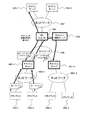
図4は、第1の実施の形態のURLスイッチ105の構成を示すブロック図である。
FIG. 4 is a block diagram illustrating a configuration of the
URLスイッチ105は、ネットワークインターフェース401−1〜401−m+1、パケット処理装置402及びメモリ403を備えるコンピュータである。これらのURLスイッチ105内の各構成は、相互に内部バス404で接続されている。
The
ネットワークインターフェース401−1は、ネットワーク102に接続されている。また、ネットワークインターフェース401−2〜401−m+1はWebサーバ104−1〜104−mに接続されている。
The network interface 401-1 is connected to the
パケット処理装置402は、入力されたパケットを所定の宛先に転送するネットワークプロセッサである。
The
メモリ403には、処理プログラムが記憶される。処理プログラムは、ハッシュ値抽出処理サブプログラム405及び転送先決定処理サブプログラム406を含む。メモリ403には、URLスイッチ105が送受信するパケットが一時的に格納されるバッファが設けられている。また、メモリ403には、転送先選択テーブル407が記憶される。
The
ハッシュ値抽出処理サブプログラム405は、クラインアント端末101−n等から送信されたコンテンツ要求からハッシュ値を抽出する。転送先決定処理サブプログラム406は、ハッシュ値抽出処理サブプログラム405によって抽出されたハッシュ値をキーとして、転送先選択テーブル407を検索し、コンテンツ要求の転送先を決定する。
The hash value
転送先選択テーブル407は、ハッシュ値と転送先との対応を格納している。 The transfer destination selection table 407 stores the correspondence between hash values and transfer destinations.
図5は、第1の実施の形態の転送先選択テーブル407の構成の説明図である。 FIG. 5 is an explanatory diagram of a configuration of the transfer destination selection table 407 according to the first embodiment.
転送先選択テーブル407は、URLのハッシュ値4071と、転送先のWebサーバのIPアドレス4072とを含む。
The transfer destination selection table 407 includes a
URLのハッシュ値4071は、コンテンツ要求に係るURLから計算された固定長のハッシュ値である。転送先4072は、当該ハッシュ値の計算の元となったURLに対応するWebサーバのIPアドレスである。すなわち、当該ハッシュ値を含むコンテンツ要求の転送先となるWebサーバのIPアドレスである。
The
URLスイッチ105は、クライアント端末101−1等から受信したコンテンツ要求に含まれるハッシュ値をキーとして、転送先選択テーブル407を検索し、転送先のWebサーバを特定する。
The
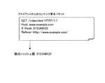
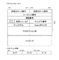
図6は、第1の実施の形態のコンテンツ要求パケットの説明図である。 FIG. 6 is an explanatory diagram of a content request packet according to the first embodiment.
クライアント端末101−1からのコンテンツ要求パケットには、X-Hashヘッダが設けられている。X-Hashヘッダには、このURLに対するハッシュ値(例えば、0123ABCD)が格納される。 An X-Hash header is provided in the content request packet from the client terminal 101-1. A hash value (for example, 0123ABCD) for this URL is stored in the X-Hash header.
このコンテンツ要求パケットを受信したURLスイッチ105は、X-Hashヘッダからハッシュ値を抽出し、コンテンツ要求パケットの転送先を決定する。
Upon receiving this content request packet, the
次に、コンテンツ要求の手順について説明する。 Next, a content request procedure will be described.
図7は、第1の実施の形態のクライアント端末101のコンテンツ要求処理のフローチャートである。
FIG. 7 is a flowchart of the content request process of the
クライアント端末101は、コンテンツを要求するURLが決定すると、ハッシュ値計算処理サブプログラム306によって、URLのハッシュ値を計算する(ステップ701)。
When the URL for requesting the content is determined, the
次に、計算したハッシュ値をコンテンツ要求のヘッダ(X-Hashヘッダ)に格納して、コンテンツ要求パケットを作成する(ステップ702)。 Next, the calculated hash value is stored in a content request header (X-Hash header) to create a content request packet (step 702).
次に、Webサーバ104−1等との間でセッションを確立する(ステップ703)。具体的には、クライアント端末101−1はURLスイッチ105と接続し、URLスイッチ105との間でセッションを確立する。
Next, a session is established with the Web server 104-1 or the like (step 703). Specifically, the client terminal 101-1 is connected to the
そして、ステップ702で作成したコンテンツ要求パケットをURLスイッチ105に対して送信する(ステップ704)。その後、URLスイッチ105経由でWebサーバ104−1等からコンテンツを受信する(ステップ705)。
Then, the content request packet created in
図8は、第1の実施の形態のURLスイッチ105のセッション中継処理のフローチャートである。このセッション中継処理は、クライアント端末101−1等からのコンテンツ要求を受信すると実行される。
FIG. 8 is a flowchart of session relay processing of the
URLスイッチ105は、クライアント端末101からのコンテンツ要求パケットを受信すると、当該コンテンツ要求パケット内のX-Hashヘッダの有無を判定する(ステップ801)。
When receiving the content request packet from the
その結果、X-Hashヘッダが存在する場合は、X-Hashヘッダからハッシュ値を抽出する(ステップ802)。このハッシュ値抽出処理は、URLを抽出するより簡単な処理である。なぜなら、可変長の文字列(URL)を抽出する処理より固定長の値(ハッシュ値)を抽出する処理の方が単純だからである。 As a result, if an X-Hash header exists, a hash value is extracted from the X-Hash header (step 802). This hash value extraction process is simpler than extracting a URL. This is because the process of extracting a fixed-length value (hash value) is simpler than the process of extracting a variable-length character string (URL).
次に、抽出されたハッシュ値をキーとして転送先検索テーブル407を検索し(ステップ803)、該当するエントリが存在するか否かを判定する(ステップ804)。 Next, the transfer destination search table 407 is searched using the extracted hash value as a key (step 803), and it is determined whether or not the corresponding entry exists (step 804).
その結果、該当エントリが発見された場合は、検索されたエントリのWebサーバ104−1を転送先に決定し、決定されたWebサーバ104−1との間でセッションを確立する(ステップ805)。 As a result, when a corresponding entry is found, the Web server 104-1 of the searched entry is determined as a transfer destination, and a session is established with the determined Web server 104-1 (step 805).
その後、クライアント端末101−1からのコンテンツ要求を転送先Webサーバ104−1に送信する(ステップ806)。 Thereafter, the content request from the client terminal 101-1 is transmitted to the transfer destination Web server 104-1 (step 806).
そして、クライアント端末101−1とWebサーバ104−1との間のセッションが切断されるまでそのセッションを中継する(ステップ807)。 The session is relayed until the session between the client terminal 101-1 and the Web server 104-1 is disconnected (step 807).
ステップ801でX-Hashヘッダが存在しない場合、又は、ステップ804で該当するエントリが発見されなかった場合は、予め定められたWebサーバを転送先に決定し、決定されたサーバとの間でセッションを確立する(ステップ808)。その後、クライアント端末からのコンテンツ要求を転送先サーバに送信する(ステップ806)。
If the X-Hash header does not exist in
X-Hashヘッダが存在しないコンテンツ要求が転送されたWebサーバは、クライアント端末101−1から送信されたURLからハッシュ値を求め、適切なWebサーバにコンテンツ要求を転送する。この場合は、URLスイッチとは別に、Webサーバも図5に示した転送先選択テーブル407を有しており、この転送先選択テーブル407に基づいて適切なWebサーバを検索する。これによって、X-Hashヘッダを埋め込むことができないクライアント端末101−1からコンテンツ要求があった場合でも、正しく負荷を分散できる。なお、コンテンツ要求が転送されたWebサーバが、通常の手順で、URLを解析し、適切なWebサーバにコンテンツ要求を転送してもよい。 The Web server to which the content request without the X-Hash header is transferred obtains a hash value from the URL transmitted from the client terminal 101-1, and transfers the content request to an appropriate Web server. In this case, in addition to the URL switch, the Web server also has the transfer destination selection table 407 shown in FIG. 5, and an appropriate Web server is searched based on this transfer destination selection table 407. As a result, even when there is a content request from the client terminal 101-1, which cannot embed the X-Hash header, the load can be distributed correctly. Note that the Web server to which the content request has been transferred may analyze the URL and transfer the content request to an appropriate Web server by a normal procedure.
このように、URLスイッチ105がセッションを中継することによって、クライアント端末101からのコンテンツ要求を適切なサーバ104に転送する。
As described above, the
図9は、第1の実施の形態のコンテンツ転送のシーケンス図である。 FIG. 9 is a sequence diagram of content transfer according to the first embodiment.
クライアント端末101−1は、URLスイッチ105との間のセッションを確立するためにTCPの3−wayハンドシェイクを行う(図7のステップ703)。
The client terminal 101-1 performs a TCP 3-way handshake to establish a session with the URL switch 105 (
具体的には、クライアント端末101−1は、URLスイッチ105に対してSYNパケットを送信して、クライアント端末101−1とURLスイッチ105との間のセッション確立を要求する。URLスイッチ105は、SYNパケットを受信すると、セッションの確立が可能であれば、SYN,ACKパケットを送信する。クライアント端末101−1は、SYN,ACKパケットを受信すると、ACKパケットを送信する。このパケットの交換によって、クライアント端末101−1とURLスイッチ105との間のセッションが確立する。
Specifically, the client terminal 101-1 transmits a SYN packet to the
そして、クライアント端末101−1は、コンテンツ要求パケットを送信する(図7のステップ704)。URLスイッチ105は、コンテンツ要求パケットを受信すると、受信したパケットからハッシュ値を抽出し(図8のステップ802)、転送先を決定する(図8のステップ803)。
Then, the client terminal 101-1 transmits a content request packet (
そして、決定された転送先Webサーバ104−1とURLスイッチ105との間のセッションを確立する(ステップ805)。その後、セッションを確立したWebサーバ104−1に対し、クライアント端末101−1からのコンテンツ要求パケットを送信する(図8のステップ806)。 Then, a session is established between the determined transfer destination Web server 104-1 and the URL switch 105 (step 805). Thereafter, a content request packet from the client terminal 101-1 is transmitted to the Web server 104-1 that has established the session (step 806 in FIG. 8).
Webサーバ104−1は、コンテンツ要求パケットを受信すると、OKパケットを送信する。URLスイッチ105は、Webサーバ104−1が送信したOKパケットを、クライアント端末101−1に転送する。また、Webサーバ104−1は、コンテンツを送信する。
When receiving the content request packet, the Web server 104-1 transmits an OK packet. The
その後、Webサーバ104−1は、コンテンツの送信が終了すると、FINパケットを送信して、セッションの終了を要求する。URLスイッチは、Webサーバ104−1が送信したFINパケットを、クライアント端末101−1に転送する。 Thereafter, when the transmission of the content ends, the Web server 104-1 transmits a FIN packet to request the end of the session. The URL switch transfers the FIN packet transmitted from the Web server 104-1 to the client terminal 101-1.
クライアント端末101−1は、FINパケットを受信すると、Webサーバ104−1との間のセッションを終了し、FIN,ACKパケットを送信する。Webサーバ104−1は、FIN,ACKパケットを受信すると、ACKパケットを送信する。このパケットの交換によって、クライアント端末101−1とWebサーバ104−1との間のセッションが終了する。 Upon receiving the FIN packet, the client terminal 101-1 ends the session with the Web server 104-1, and transmits a FIN / ACK packet. When the Web server 104-1 receives the FIN / ACK packet, the Web server 104-1 transmits an ACK packet. By exchanging this packet, the session between the client terminal 101-1 and the Web server 104-1 is terminated.
以上説明したように、第1の実施の形態では、クライアント端末がURLからハッシュ値を求めることによって、URLスイッチにおける識別子抽出、計算処理を単純化している。これにより、URLスイッチに実装が必要なプログラム量及び価格を削減することができ、高速な負荷分散を実現することができる。 As described above, in the first embodiment, the client terminal obtains the hash value from the URL, thereby simplifying the identifier extraction and calculation processing in the URL switch. As a result, it is possible to reduce the amount of program and the price that need to be implemented in the URL switch, and to realize high-speed load distribution.
すなわち、第1の実施の形態では、クライアントからのコンテンツ要求の転送先決定処理のうち、URL抽出処理を簡略化する。このため、クライアント端末においてURLから固定長のハッシュ値を生成し、その値をコンテンツ要求に含める。これによって、URLスイッチが抽出すべき値が可変長の長い文字列から、固定長の短い文字列になる。これによってURLスイッチによる処理を軽減することができる。 That is, in the first embodiment, the URL extraction process is simplified in the process for determining the transfer destination of the content request from the client. For this reason, a fixed-length hash value is generated from the URL at the client terminal, and the value is included in the content request. As a result, the value to be extracted by the URL switch is changed from a variable-length long character string to a fixed-length short character string. As a result, processing by the URL switch can be reduced.
また、URLスイッチによる転送先決定処理に使用されるデータがURLからハッシュ値になることによって、データ量が約50バイトから数バイトに減る。これによって、URLスイッチの記憶容量を削減することができる。 In addition, since the data used for the transfer destination determination process by the URL switch is changed from the URL to the hash value, the data amount is reduced from about 50 bytes to several bytes. Thereby, the storage capacity of the URL switch can be reduced.
(実施形態2)
次に、本発明を、分散キャッシュを備えるコンピュータシステムに適用した例を説明する。
(Embodiment 2)
Next, an example in which the present invention is applied to a computer system having a distributed cache will be described.
キャッシュサーバは、クライアント端末とコンテンツサーバ(オリジンサーバ)との間に設けられる。キャッシュサーバは、クライアント端末からのコンテンツ要求に対してサーバを代理して返信することによって、クライアント端末への応答時間の短縮、コンテンツサーバの負荷低減、及びキャッシュサーバとコンテンツサーバとの間のトラフィックの削減をしている。 The cache server is provided between the client terminal and the content server (origin server). The cache server responds to the content request from the client terminal on behalf of the server, thereby shortening the response time to the client terminal, reducing the load on the content server, and reducing the traffic between the cache server and the content server. We are reducing.
キャッシュサーバは、より多数のクライアント端末を収容することによって、複数のクライアント端末から要求される共通のコンテンツの記憶量を増やし、キャッシュのヒット率を向上させる。 The cache server accommodates a larger number of client terminals, thereby increasing the storage amount of common content requested from a plurality of client terminals and improving the cache hit rate.
しかし、多数のクライアント端末からのコンテンツ要求がキャッシュサーバに集中するため、キャッシュサーバの処理性能がボトルネックとなる。これを解決するため、複数のキャッシュサーバでクライアント端末を分担し、かつキャッシュされたコンテンツを共有することによって、コンテンツの記憶量の増大と、サーバのボトルネック解消の両者を実現する。 However, since content requests from a large number of client terminals are concentrated on the cache server, the processing performance of the cache server becomes a bottleneck. In order to solve this, the client terminal is shared by a plurality of cache servers, and the cached content is shared, thereby realizing both an increase in the storage amount of the content and elimination of the bottleneck of the server.
このような分散型キャッシュとして、2つの方法が考えられる。 As such a distributed cache, two methods are conceivable.
第1の方法は、分散された複数のキャッシュサーバ同士が直接通信し、お互いのキャッシュしているコンテンツの情報を交換するものである。この方法は、Internet Cache Protocolとして、RFC2186、"Internet Cache Protocol (ICP)" に詳しく記載されている。 In the first method, a plurality of distributed cache servers communicate directly with each other and exchange information on contents cached with each other. This method is described in detail in RFC 2186, “Internet Cache Protocol (ICP)” as the Internet Cache Protocol.
第2の方法は、キャッシュされたコンテンツの情報を制御サーバにて集中的に管理し、各キャッシュサーバは制御サーバの指示に従ってコンテンツを取得するものである。このような分散キャッシュ制御方法は、例えば、特開2005−10970号公報に記載されている。 In the second method, the cached content information is centrally managed by the control server, and each cache server acquires the content in accordance with an instruction from the control server. Such a distributed cache control method is described in, for example, Japanese Patent Application Laid-Open No. 2005-10970.
第1の方法は第2の方法と比較して、多数のキャッシュサーバが互いに通信する。すなわち、第1の方法は、キャッシュサーバ間の通信が、サーバ台数の2乗に比例して増加する。よって、第1の方法はスケーラビリティが低い。 In the first method, more cache servers communicate with each other than in the second method. In other words, in the first method, communication between cache servers increases in proportion to the square of the number of servers. Therefore, the first method has low scalability.
一方、第2の方法では、キャッシュの有無に関する問い合わせが制御サーバに集中する。この解決のために、制御サーバの処理を、URLスイッチを利用した専用機器に移し、制御サーバをオフロードする。このため、ネットワークプロセッサなどのパケット処理に特化した機器を用い、パケット処理を効率化する必要がある。 On the other hand, in the second method, inquiries regarding the presence or absence of a cache are concentrated on the control server. In order to solve this, the processing of the control server is transferred to a dedicated device using a URL switch, and the control server is offloaded. For this reason, it is necessary to use a device specialized for packet processing such as a network processor to improve the efficiency of packet processing.
しかし、パケット処理に特化した機器では、パケットに対して行える処理は限られている。例えば、特定の位置に存在する固定長の情報は高速に抽出できるが、URLのような可変長の文字列を高速に扱うことはできない。 However, in a device specialized for packet processing, processing that can be performed on packets is limited. For example, fixed-length information existing at a specific position can be extracted at high speed, but variable-length character strings such as URLs cannot be handled at high speed.
これを解決するため、第2の実施の形態では、キャッシュサーバから制御サーバへのコンテンツ要求パケット中にURLのハッシュ値を埋め込む。これによって、パケット処理に特化した機器においてもURLの解析と同等の処理を高速に行うことができる。 In order to solve this, in the second embodiment, the hash value of the URL is embedded in the content request packet from the cache server to the control server. As a result, even in a device specialized for packet processing, processing equivalent to URL analysis can be performed at high speed.
第2の実施の形態においても、実施例1と同様に、URLのハッシュ計算にCRC32を利用する。 In the second embodiment, as in the first embodiment, the CRC 32 is used for URL hash calculation.
図10は、第2の実施の形態のコンピュータシステムの構成を示すブロック図である。 FIG. 10 is a block diagram illustrating a configuration of a computer system according to the second embodiment.
第1の実施の形態のコンピュータシステムは、キャッシュサーバ1001−1〜1001−2、クライアント端末1002−1〜1002−4、ネットワーク1003−1〜1003−2、URLスイッチ1004、オリジンサーバ1005−1〜1005−2、ネットワーク1006、ネットワーク1007及びキャッシュ制御サーバ1008によって構成されている。
The computer system according to the first embodiment includes cache servers 1001-1 to 1001-2, client terminals 1002-1 to 1002-4, networks 1003-1 to 1003-2,
クライアント端末1002−1等は、オリジンサーバ1005−1等に、HTTPプロトコルによってコンテンツを要求するコンピュータである。クライアント端末1002−1等は、前述した第1の実施の形態のクライアント端末101−1と同じ構成を有する(図2参照)。 The client terminal 1002-1 or the like is a computer that requests content from the origin server 1005-1 or the like using the HTTP protocol. The client terminal 1002-1 and the like have the same configuration as the client terminal 101-1 of the first embodiment described above (see FIG. 2).
キャッシュサーバ1001−1、1001−2は、クライアント端末1002−1等がオリジンサーバ1005−1等から取得したコンテンツを記憶する。 The cache servers 1001-1 and 1001-2 store contents acquired by the client terminal 1002-1 and the like from the origin server 1005-1 and the like.
URLスイッチ1004は、クライアント端末1002−1等からのコンテンツ要求パケットを解析して、キャッシュが記憶されているか否かを判定し、コンテンツ要求を振り分ける負荷分散装置である。第2の実施の形態のコンピュータシステムでは、URLのハッシュ値がコンテンツ要求パケットに含まれているので、URLスイッチ1004は、このURLのハッシュ値を用いてキャッシュの有無を判定する。
The
オリジンサーバ1005−1及び1005−2は、はクライアント端末1002−1等にコンテンツを提供するコンピュータである。 Origin servers 1005-1 and 1005-2 are computers that provide content to the client terminal 1002-1 and the like.
各キャッシュサーバ1001−1、1001−2は、一つ以上のクライアント端末1002−1等とネットワーク1003−1等を介して接続されている。URLスイッチ1004は、キャッシュサーバ1001−1等とURLスイッチ1004とはネットワーク1006を介して接続されている。また、URLスイッチ1004とオリジンサーバ1005−1等とはネットワーク1007を介して接続されている。URLスイッチ1004には、キャッシュ制御サーバ1008が接続されている。これらのネットワーク1003−1、1003−2、1006及び1007は、例えば、TCP/IPプロトコルによって通信可能である。
Each of the cache servers 1001-1 and 1001-2 is connected to one or more client terminals 1002-1 and the like via the network 1003-1 and the like. In the
図11は、第2の実施の形態のキャッシュサーバ1001−1の構成を示すブロック図である。なお、図11には、キャッシュサーバ1001−1の構成を示すが、他のキャッシュサーバ1001−2も同じ構成を有する。 FIG. 11 is a block diagram illustrating a configuration of the cache server 1001-1 according to the second embodiment. FIG. 11 shows the configuration of the cache server 1001-1, but the other cache servers 1001-2 have the same configuration.
キャッシュサーバ1001−1は、インターフェース1101−1及び1101−2、1102、メモリ1103及び二次記憶装置1104を備えるコンピュータ装置である。これらのキャッシュサーバ1001−1内の各構成は相互に内部バス1105で接続されている。
The cache server 1001-1 is a computer device that includes interfaces 1101-1 and 1101-2, 1102, a
インターフェース1101−1は、クライアント端末側のネットワーク1003に接続されている。インターフェース1101−2は、他のキャッシュサーバおよびURLスイッチに接続されている。 The interface 1101-1 is connected to the network 1003 on the client terminal side. The interface 1101-2 is connected to other cache servers and URL switches.
CPU1102は、メモリ1103に記憶されている各種プログラムを実行し、キャッシュサーバを制御する。
The
メモリ1103には、処理プログラムが記憶される。処理プログラムは、キャッシュ有無判定処理サブプログラム1106、ハッシュ値計算処理サブプログラム1107、コンテンツ要求処理サブプログラム1108及びコンテンツ登録処理サブプログラム1109を含む。
The
キャッシュ有無判定処理サブプログラム1106は、二次記憶装置1104内に格納されたコンテンツデータベース1110を検索し、ユーザが要求するコンテンツを当該キャッシュサーバが格納しているか否かを判定する。
The cache presence / absence
ハッシュ値計算処理サブプログラム1107は、クラインアント端末1002−1等から送信されたコンテンツ要求に係るURLから固定長のハッシュ値を計算する。
The hash value
コンテンツ要求処理サブプログラム1108は、クラインアント端末1002−1等から要求されたコンテンツが、当該キャッシュサーバに格納されていないときに、キャッシュ制御サーバ1008にコンテンツを要求する。
The content
コンテンツ登録処理サブプログラム1109は、URLスイッチ1004を経由してオリジンサーバ1005−1等から、又は直接他のキャッシュサーバ1001−2からコンテンツを取得する。そして、その内容を当該キャッシュのコンテンツデータベース1110内に格納する。
The content
二次記憶装置1104は、キャッシュサーバ1001−1の電源遮断時も記憶内容を保持するハードディスク装置であり、コンテンツデータベース1110が格納されている。
The
コンテンツデータベース1110は、コンテンツと当該コンテンツのURLとの対応を格納している。
The
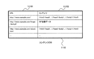
図12は、第2の実施の形態のコンテンツデータベース1110の構成の説明図である。
FIG. 12 is an explanatory diagram of a configuration of the
コンテンツデータベース1110は、URL11101と、コンテンツ11102とを含む。
The
URL11101は、当該コンテンツがオリジンサーバに格納されている場所を示すURLである。コンテンツ11102は、コンテンツのデータそのものである。
キャッシュサーバ1001−1は、クライアント端末1002−1等から受信したコンテンツ要求に含まれるURLをキーとして、コンテンツデータベース1110を検索し、当該キャッシュサーバにコンテンツが格納されているかを判定する。
The cache server 1001-1 searches the
図13は、第2の実施の形態のURLスイッチ1004の構成を示すブロック図である。
FIG. 13 is a block diagram illustrating a configuration of the
URLスイッチ1004は、ネットワークインターフェース1201−1〜1201−3、パケット処理装置1202及びメモリ1203を備えるコンピュータである。これらの各構成は、相互に内部バス1204で接続されている。
The
ネットワークインターフェース1201−1は、ネットワーク1006に接続されている。ネットワークインターフェース1201−2は、キャッシュ制御サーバ1008に接続されている。また、ネットワークインターフェース1201−3はネットワーク1007に接続されている。
The network interface 1201-1 is connected to the
パケット処理装置1202は、入力されたパケットを所定の宛先に転送するネットワークプロセッサである。
The
メモリ1203には、処理プログラムが記憶される。処理プログラムは、ハッシュ値抽出処理サブプログラム1205、転送先決定処理サブプログラム1206及びハッシュ値登録処理サブプログラム1207を含む。メモリ1203には、URLスイッチ1004が送受信するパケットが一時的に格納されるバッファが設けられている。また、メモリ1203には、転送先選択テーブル1208が記憶される。
The
ハッシュ値抽出処理サブプログラム1205は、クラインアント端末1002−1等から送信されたコンテンツ要求からハッシュ値を抽出する。転送先決定処理サブプログラム1206は、ハッシュ値抽出処理サブプログラム1205によって抽出されたハッシュ値をキーとして、転送先選択テーブル1208を検索し、コンテンツ要求の転送先を決定する。ハッシュ値登録処理サブプログラム1207は、転送先選択テーブル1208へのハッシュ値の登録要求及び削除要求を受け付ける。
The hash value
転送先選択テーブル1208は、ハッシュ値と転送先との対応を格納する。 The transfer destination selection table 1208 stores the correspondence between hash values and transfer destinations.
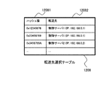
図14は、第2の実施の形態の転送先選択テーブル1208の構成の説明図である。 FIG. 14 is an explanatory diagram of a configuration of the transfer destination selection table 1208 according to the second embodiment.
転送先選択テーブル1208は、システム内のキャッシュサーバに格納される全てのキャッシュのデータを含む。各データは、URLのハッシュ値12081と、転送先のキャッシュ制御サーバのIPアドレス12082とを含む。
The transfer destination selection table 1208 includes data of all caches stored in the cache server in the system. Each data includes a
URLのハッシュ値12081は、コンテンツ要求に係るURLから計算された固定長のハッシュ値である。転送先12082は、当該ハッシュ値の計算の元となったURLに対応するキャッシュを格納するキャッシュサーバを制御するキャッシュ制御サーバのIPアドレスである。すなわち、転送先12082は、当該ハッシュ値が含まれるコンテンツ要求の転送先となるキャッシュ制御サーバのIPアドレスである。
The
URLスイッチ1004は、キャッシュサーバ1001−1等から受信したコンテンツ要求に含まれるハッシュ値をキーとして、転送先選択テーブル1208を検索し、転送先のキャッシュ制御サーバを特定する。
The
図15は、第2の実施の形態のキャッシュ制御サーバ1008の構成を示すブロック図である。
FIG. 15 is a block diagram illustrating a configuration of the
キャッシュ制御サーバ1008は、ネットワークインターフェース1301、CPU1302、メモリ1303及び二次記憶装置1304を備えるコンピュータである。これらの各構成は、相互に内部バス1306で接続されている。
The
ネットワークインターフェース1301は、URLスイッチ1004に接続されている。
The
CPU1302は、メモリ1303に記憶されている各種プログラムを実行し、制御サーバを制御する。
The
メモリ1303には、処理プログラムが記憶される。処理プログラムは、キャッシュ有無判定処理サブプログラム1307、コンテンツ転送指示処理サブプログラム1308及びURL登録処理サブプログラム1309を含む。
The
キャッシュ有無判定処理サブプログラム1307は、URLスイッチから送信されたコンテンツ要求パケットからURLを抽出し、キャッシュ所在データベース1305を検索して、キャッシュを保有するキャッシュサーバを決定する。
The cache presence / absence
コンテンツ転送指示処理サブプログラム1308は、キャッシュを保有するキャッシュサーバに、コンテンツの転送を指示する。
The content transfer
URL登録処理サブプログラム1309は、キャッシュサーバが取得したコンテンツの情報を、キャッシュ所在データベースに登録する。
The URL
二次記憶装置1304は、プロキシサーバ103の電源遮断時も記憶内容を保持するハードディスク装置であり、キャッシュ所在データベース1305が格納されている。
The
キャッシュ所在DB1305は、URLのハッシュ値とコンテンツ要求の転送先との対応を格納している。
The
図16は、第2の実施の形態のキャッシュ所在データベース1305の構成の説明図である。
FIG. 16 is an explanatory diagram of a configuration of the
キャッシュ所在データベース1305は、URL13051と、キャッシュを格納するキャッシュサーバのIPアドレス13052とを含む。
The
URL13051は、当該コンテンツがオリジンサーバに格納されている場所を示すURLである。キャッシュサーバ13052は、当該コンテンツが格納されているキャッシュサーバのIPアドレスである。キャッシュ制御サーバ1008は、キャッシュサーバ1001−1等から受信したコンテンツ要求に含まれるURLをキーとして、キャッシュ所在データベース1305を検索し、どのキャッシュサーバにコンテンツが格納されているかを判定する。
The
図17、図18は、第2の実施の形態のコンテンツ要求パケットの説明図である。 17 and 18 are explanatory diagrams of a content request packet according to the second embodiment.
図17は、クライアント端末1002からのコンテンツ要求パケットを示す。コンテンツ要求パケットには、要求するコンテンツのURLが含まれている。 FIG. 17 shows a content request packet from the client terminal 1002. The content request packet includes the URL of the requested content.
キャッシュサーバ1001−1は、クライアント端末1002からのコンテンツ要求パケットを受信すると、受信したパケットからURLを抽出する。具体的には、Refererヘッダーから"http://www.example.com/”を抽出し、GETヘッダーから"index.html"を抽出する。そして、これらを合成し、URL"http://www.example.com/index.html"を得る。 When the cache server 1001-1 receives the content request packet from the client terminal 1002, the cache server 1001-1 extracts the URL from the received packet. Specifically, “http://www.example.com/” is extracted from the Referer header, and “index.html” is extracted from the GET header. These are combined to obtain the URL “http://www.example.com/index.html”.
図18は、キャッシュサーバ1001−1からのコンテンツ要求パケットを示す。 FIG. 18 shows a content request packet from the cache server 1001-1.
キャッシュサーバ1001−1からのコンテンツ要求パケットは、クライアント端末1002−1からのコンテンツ要求パケット(図17)に、X-Hashヘッダが付加されている。X-Hashヘッダには、このURLに対するハッシュ値(例えば、0123ABCD)が格納される。 In the content request packet from the cache server 1001-1, an X-Hash header is added to the content request packet (FIG. 17) from the client terminal 1002-1. A hash value (for example, 0123ABCD) for this URL is stored in the X-Hash header.
このコンテンツ要求パケットを受信したURLスイッチ105は、X-Hashヘッダからハッシュ値を抽出し、コンテンツ要求パケットの転送先を決定する。
Upon receiving this content request packet, the
また、キャッシュ制御サーバ1008は、キャッシュサーバ1001−1等からのコンテンツ要求パケットを受信すると、受信したパケットからURLを抽出し、"http://www.example.com/index.html"を得る。
When the
次に、コンテンツ要求の手順について説明する。 Next, a content request procedure will be described.
図19は、第2の実施の形態のキャッシュサーバ1001−1のコンテンツ要求処理のフローチャートである。 FIG. 19 is a flowchart of the content request process of the cache server 1001-1 according to the second embodiment.
まず、キャッシュサーバ1001は、クライアント端末1002−1からのコンテンツ要求パケット(図17)を受信すると、コンテンツ要求パケットに含まれているコンテンツのURLを抽出する(ステップ1501)。そして、抽出したURLをキーにして、コンテンツデータベース1110を検索し(ステップ1502)、該当するコンテンツが存在するか否かを判定する(ステップ1503)。
First, when receiving the content request packet (FIG. 17) from the client terminal 1002-1, the cache server 1001 extracts the URL of the content included in the content request packet (step 1501). Then, the
その結果、クライアント端末1002−1が要求するコンテンツがコンテンツデータベース1110に存在する場合、コンテンツデータベース1110からコンテンツを取得し、取得したコンテンツをクライアント端末1002−1に送信する(ステップ1504)。
As a result, when the content requested by the client terminal 1002-1 exists in the
一方、当該コンテンツがコンテンツデータベース1110に存在しない場合、キャッシュサーバ1001は、ハッシュ値計算処理サブプログラム1107によって、要求のコンテンツのURLからハッシュ値を計算する(ステップ1505)。そして、計算したハッシュ値をコンテンツ要求のヘッダ(X-Hashヘッダ)に格納したコンテンツ要求パケットを作成し、作成したコンテンツ要求パケットを、オリジンサーバ1005−1に送信する(ステップ1506)。このコンテンツ要求はURLスイッチ1004を経由する。
On the other hand, if the content does not exist in the
このコンテンツ要求に対して、2通りの返信が存在する。第一の返信は、オリジンサーバ1005−1から転送されるコンテンツである。この場合、キャッシュサーバ1001−1はオリジンサーバ1005−1からコンテンツを受信する(ステップ1508)。 There are two replies to this content request. The first reply is content transferred from the origin server 1005-1. In this case, the cache server 1001-1 receives content from the origin server 1005-1 (step 1508).
一方、第二の返信は、他のキャッシュサーバ1001−2から転送されるコンテンツである。この場合、要求元キャッシュサーバ1001−1は、キャッシュ制御サーバ1008から他のキャッシュサーバ1001−2からコンテンツが転送される旨を受信し、その後、他のキャッシュサーバ1001−2からコンテンツを受信する(ステップ1511)。
On the other hand, the second reply is content transferred from the other cache server 1001-2. In this case, the request source cache server 1001-1 receives from the
要求元キャッシュサーバ1001−1は、コンテンツを受信した後、受信したコンテンツをクライアント端末1002−1に転送する(ステップ1509)。その後、コンテンツデータベース1110にコンテンツを登録する(ステップ1510)。そして、当該キャッシュにコンテンツが追加されたことをキャッシュ制御サーバ1008に送信する(ステップ1512)。 After receiving the content, the request source cache server 1001-1 transfers the received content to the client terminal 1002-1 (step 1509). Thereafter, the content is registered in the content database 1110 (step 1510). Then, the fact that the content has been added to the cache is transmitted to the cache control server 1008 (step 1512).
図20は、第2の実施の形態のURLスイッチ1004のコンテンツ要求処理のフローチャートである。
FIG. 20 is a flowchart of the content request process of the
URLスイッチ1004は、キャッシュサーバ1001−1等とオリジンサーバ1005−1等との間に設けられている。よって、URLスイッチ1004は、キャッシュサーバ1001−1からオリジンサーバ1005へのコンテンツ要求パケット(図18)を捕捉することができる。
The
URLスイッチ1004は、キャッシュサーバ1001からオリジンサーバ1005へのコンテンツ要求パケットを捕捉すると、捕捉したパケットからURLのハッシュ値を抽出する(ステップ1601)。そして、抽出したハッシュ値をキーとして、転送先選択テーブル1208を検索し(ステップ1602)、該当するエントリが存在するか否かを判定する(ステップ1603)。
When the
その結果、転送先選択テーブルに対応するエントリが存在した場合、いずれかのキャッシュサーバに当該コンテンツが存在する。よって、検索されたエントリに記載された制御サーバを転送先と決定し、決定された制御サーバにコンテンツ要求パケットを転送する(ステップ1604)。 As a result, when there is an entry corresponding to the transfer destination selection table, the content exists in one of the cache servers. Therefore, the control server described in the searched entry is determined as the transfer destination, and the content request packet is transferred to the determined control server (step 1604).
一方、対応するエントリが存在しない場合、いずれのキャッシュサーバにも当該コンテンツが存在しない。よって、URLスイッチはコンテンツ要求パケットをオリジンサーバ1005−1へ転送する(ステップ1605)。キャッシュサーバ1001から送信されたコンテンツ要求パケットの宛先はオリジンサーバ1005−1なので、URLスイッチ1004はオリジンサーバ1005−1のIPアドレスを取得する必要はない。
On the other hand, if there is no corresponding entry, the content does not exist in any cache server. Therefore, the URL switch transfers the content request packet to the origin server 1005-1 (step 1605). Since the destination of the content request packet transmitted from the cache server 1001 is the origin server 1005-1, the
図21は、第2の実施の形態のキャッシュ制御サーバ1008のコンテンツ要求処理のフローチャートである。
FIG. 21 is a flowchart of the content request process of the
制御サーバ1008は、URLスイッチ1004から転送されたコンテンツ要求パケットを受信すると、コンテンツ要求パケットからコンテンツのURLを抽出する(ステップ1701)。そして、抽出したURLをキーとして、キャッシュ所在データベース1305を検索し(ステップ1702)、該当するエントリが存在するか否かを判定する(ステップ1703)。
Upon receiving the content request packet transferred from the
当該URLに対するエントリが存在した場合、他のキャッシュサーバに当該コンテンツが存在する。よって、要求元キャッシュサーバ1001−1に対して、他のキャッシュサーバ1001−2からコンテンツが転送される旨を返信する。そして、検索されたエントリに含まれるキャッシュサーバ1001−2を選択し、当該URLのコンテンツを要求元のキャッシュサーバ1001−1に対して転送する指示をする(ステップ1704)。 If there is an entry for the URL, the content exists in another cache server. Therefore, a response that the content is transferred from the other cache server 1001-2 is returned to the request source cache server 1001-1. Then, the cache server 1001-2 included in the searched entry is selected, and an instruction to transfer the content of the URL to the requesting cache server 1001-1 is given (step 1704).
一方、当該URLに対するエントリが存在しなかった場合、URLスイッチ1004によるキャッシュの有無判定が間違っていたことになる。URLスイッチ1004では、ハッシュ値に基づいてキャッシュの有無を判定しているので、ハッシュ値の衝突が生じうる。
On the other hand, if there is no entry for the URL, it means that the
このため、キャッシュ所在データベース1305にエントリが存在しなかった場合は、キャッシュ制御サーバ1008はオリジンサーバ1005−1にコンテンツ要求パケットを転送し、コンテンツを取得する(ステップ1705)。
Therefore, if there is no entry in the
そして、オリジンサーバ1005−1から得られたコンテンツを要求元キャッシュサーバ1001−1に返信する(ステップ1706)。そして、要求元キャッシュサーバ1001−1は、コンテンツをクライアント端末1002−1に転送し、当該コンテンツをキャッシュに格納する。 Then, the content obtained from the origin server 1005-1 is returned to the request source cache server 1001-1 (step 1706). Then, the request source cache server 1001-1 transfers the content to the client terminal 1002-1 and stores the content in the cache.
図22、図23は、第2の実施の形態のコンテンツ転送のシーケンス図である。 22 and 23 are sequence diagrams of content transfer according to the second embodiment.
図22は、キャッシュサーバから要求されたコンテンツが、いずれのキャッシュサーバにも存在しない場合のシーケンスを示す。 FIG. 22 shows a sequence in the case where the content requested from the cache server does not exist in any cache server.
キャッシュサーバ1001−1は、クライアント端末からコンテンツ要求パケットを受信すると、URLスイッチ1004との間のセッションを確立するためにTCPの3−wayハンドシェイクを行う。
Upon receiving the content request packet from the client terminal, the cache server 1001-1 performs a TCP 3-way handshake to establish a session with the
具体的には、キャッシュサーバ1001−1は、URLスイッチ1004に対してSYNパケットを送信して、キャッシュサーバ1001−1とURLスイッチ1004との間のセッション確立を要求する。URLスイッチ1004は、SYNパケットを受信すると、セッションの確立が可能であれば、SYN,ACKパケットを送信する。キャッシュサーバ1001−1は、SYN,ACKパケットを受信すると、ACKパケットを送信する。このパケットの交換によって、キャッシュサーバ1001−1とURLスイッチ1004との間のセッションが確立する。
Specifically, the cache server 1001-1 transmits a SYN packet to the
そして、キャッシュサーバ1001−1は、クライアント端末から受信したコンテンツ要求パケットを受信すると、受信したパケットにURLのX-Hash値を追加して、URLスイッチ1004に送信する(図19のステップ1506)。URLスイッチ1004は、コンテンツ要求パケットを受信すると、受信したパケットからハッシュ値を抽出し(図20のステップ1601)、転送先を決定する(図20のステップ1602)。
Then, when receiving the content request packet received from the client terminal, the cache server 1001-1 adds the X-Hash value of the URL to the received packet and transmits it to the URL switch 1004 (
図22に示す場合は、転送先選択テーブル1208に該当するエントリが存在しないので(要求されたコンテンツがキャッシュサーバに存在しないので)、オリジンサーバ1005−11005−1にコンテンツ要求パケットを転送する。このため、URLスイッチ1004とオリジンサーバ1005−1との間のセッションを確立する。その後、URLスイッチ1004は、セッションを確立したオリジンサーバ1005−1に対し、クライアント端末からのコンテンツ要求パケットを送信する(図20のステップ1605)。
In the case shown in FIG. 22, since there is no corresponding entry in the transfer destination selection table 1208 (since the requested content does not exist in the cache server), the content request packet is transferred to the origin server 1005-11005-1. Therefore, a session is established between the
オリジンサーバ1005−1は、コンテンツ要求パケットを受信すると、OKパケットを送信する。URLスイッチ1004は、オリジンサーバ1005−1が送信したOKパケットを、キャッシュサーバ1001−1に転送する。また、オリジンサーバ1005−1は、コンテンツを送信する。
When the origin server 1005-1 receives the content request packet, the origin server 1005-1 transmits an OK packet. The
その後、オリジンサーバ1005−1は、コンテンツの送信が終了すると、FINパケットを送信する。URLスイッチ1004は、オリジンサーバ1005−1が送信したFINパケットを、キャッシュサーバ1001−1に転送する。
Thereafter, the origin server 1005-1 transmits a FIN packet when the content transmission is completed. The
キャッシュサーバ1001−1は、FINパケットを受信すると、オリジンサーバ1005−1との間のセッションを終了し、FIN,ACKパケットを送信する。オリジンサーバ1005−1は、FIN,ACKパケットを受信すると、ACKパケットを送信する。このパケットの交換によって、キャッシュサーバ1001−1とオリジンサーバ1005−1との間のセッションが終了する。 When the cache server 1001-1 receives the FIN packet, the cache server 1001-1 terminates the session with the origin server 1005-1 and transmits a FIN / ACK packet. When the origin server 1005-1 receives the FIN / ACK packet, the origin server 1005-1 transmits the ACK packet. This packet exchange ends the session between the cache server 1001-1 and the origin server 1005-1.
その後、キャッシュサーバ1001−1は、転送されたコンテンツのURLをキャッシュ制御サーバ1008に送る。キャッシュ制御サーバ1008は、受信したURLを、キャッシュ所在データベース1305に追加する。
Thereafter, the cache server 1001-1 sends the URL of the transferred content to the
その後、キャッシュ制御サーバ1008は、受信したURLのハッシュ値を計算し、計算したハッシュ値をURLスイッチ1004に送る。URLスイッチ1004は、転送されたハッシュ値を、当該ハッシュ値を計算したキャッシュ制御サーバ1008と対応付けて、転送先選択テーブル1208に追加する。
Thereafter, the
図23は、他のキャッシュサーバが要求のコンテンツを格納していた場合のシーケンスを示す。 FIG. 23 shows a sequence in the case where another cache server stores the requested content.
要求元キャッシュサーバ1001−1は、クライアント端末からコンテンツ要求パケットを受信すると、URLスイッチ1004との間のセッションを確立するために、TCPの3−wayハンドシェイクを行う。この手順は図22に示したものと同様である。
Upon receiving the content request packet from the client terminal, the request source cache server 1001-1 performs a TCP three-way handshake to establish a session with the
そして、要求元キャッシュサーバ1001−1は、クライアント端末から受信したコンテンツ要求パケットを受信すると、受信したパケットにURLのX-Hash値を追加して、URLスイッチ1004に送信する(図19のステップ1506)。URLスイッチ1004は、コンテンツ要求パケットを受信すると、受信したパケットからハッシュ値を抽出し(図20のステップ1601)、転送先を決定する(図20のステップ1602)。
Upon receiving the content request packet received from the client terminal, the request source cache server 1001-1 adds the X-Hash value of the URL to the received packet and transmits it to the URL switch 1004 (
図23に示す場合は、転送先選択テーブル1208に該当するエントリが存在するので(要求されたコンテンツがキャッシュサーバに存在するので)、他のキャッシュサーバ1001−2からコンテンツを取得する。このため、URLスイッチ1004とキャッシュ制御サーバ1008との間のセッションを確立する。その後、URLスイッチ1004は、キャッシュ制御サーバ1008に対し、クライアント端末からのコンテンツ要求パケットを送信する(図20のステップ1604)。
In the case shown in FIG. 23, since the corresponding entry exists in the transfer destination selection table 1208 (because the requested content exists in the cache server), the content is acquired from the other cache server 1001-2. Therefore, a session between the
キャッシュ制御サーバ1008は、コンテンツ要求パケットを受信すると、キャッシュ所在データベース1305を検索して、要求コンテンツを格納するキャッシュサーバ1001−2を特定する(図21のステップ1702)。そして、特定されたキャッシュサーバ1001−2にコンテンツの転送を指示する(図21のステップ1704)。
When receiving the content request packet, the
要求コンテンツを格納するキャッシュサーバ1001−2は、要求元キャッシュサーバ1001−1にコンテンツを送信する。 The cache server 1001-2 that stores the requested content transmits the content to the request source cache server 1001-1.
その後、コンテンツの送信が終了すると、キャッシュ制御サーバ1008は、FINパケットを送信する。URLスイッチ1004は、キャッシュ制御サーバ1008が送信したFINパケットを、キャッシュサーバ1001−1に転送する。
After that, when the content transmission ends, the
キャッシュサーバ1001−1は、FINパケットを受信すると、キャッシュ制御サーバ1008との間のセッションを終了し、FIN,ACKパケットを送信する。キャッシュ制御サーバ1008は、FIN,ACKパケットを受信すると、ACKパケットを送信する。このパケットの交換によって、キャッシュサーバ1001−1とキャッシュ制御サーバ1008との間のセッションが終了する。
When the cache server 1001-1 receives the FIN packet, the cache server 1001-1 ends the session with the
その後、キャッシュサーバ1001−1は、転送されたコンテンツのURLをキャッシュ制御サーバ1008に送る。キャッシュ制御サーバ1008は、受信したURLを、キャッシュ所在データベース1305に追加する。
Thereafter, the cache server 1001-1 sends the URL of the transferred content to the
以上説明したように、第2の実施の形態では、URLスイッチ1004においてURLのハッシュ値を用いて転送先を判定している。よって、従来、制御サーバにかかっていた負荷をURLスイッチ1004にオフロードすることができる。
As described above, in the second embodiment, the
また、キャッシュサーバ1001−1でURLのハッシュ値を求め、URLスイッチ1004が当該ハッシュ値を用いてキャッシュ有無を判定するので、URLスイッチ1004の処理負荷を軽減することができる。また、第1の実施の形態と同様に、URLスイッチ1004が、URLの抽出に代わってハッシュ値を抽出することによって、URLスイッチ1004における処理を単純化することができる。
Further, the cache server 1001-1 obtains the hash value of the URL, and the
(実施形態3)
第1及び第2の実施の形態では、サーバとクライアント端末間のセッションを確立した後に交換されるパケットにハッシュ値を埋め込んだ。以下に説明する第3の実施の形態では、TCPセッション確立時にハッシュ値を埋め込んだパケットを使用する。
(Embodiment 3)
In the first and second embodiments, a hash value is embedded in a packet exchanged after establishing a session between the server and the client terminal. In the third embodiment described below, a packet in which a hash value is embedded when a TCP session is established is used.
図24は、第3の実施の形態のTCPのヘッダフォーマットの説明図である。 FIG. 24 is an explanatory diagram of a TCP header format according to the third embodiment.
TCPにおけるセッションの確立時に送信されるパケットは、TCPヘッダの制御フィールドにセッション確立要求であることを示すSYNフラグが設定されている。第3の実施の形態では、SYNパケットのTCPオプション列の中に、要求するコンテンツのURLのハッシュ値を埋め込む。 A packet transmitted when establishing a session in TCP has a SYN flag indicating that it is a session establishment request in the control field of the TCP header. In the third embodiment, the hash value of the URL of the requested content is embedded in the TCP option string of the SYN packet.
このため、第3の実施の形態を実現するためには、クライアント端末に実装されている既存のTCPスタックを改造する必要がある。よって、第1及び第2の実施の形態の方法と、第3の実施の形態の方法とは、利用形態によって使い分けることが望ましい。 Therefore, in order to realize the third embodiment, it is necessary to modify the existing TCP stack mounted on the client terminal. Therefore, it is desirable to use the method according to the first and second embodiments and the method according to the third embodiment properly depending on the usage pattern.
なお、第3の実施の形態は、第1の実施の形態のコンピュータシステム(図1)及び第2の実施の形態のコンピュータシステム(図10)のいずれにも適用することができる。 Note that the third embodiment can be applied to both the computer system of the first embodiment (FIG. 1) and the computer system of the second embodiment (FIG. 10).
次に、第3の実施の形態を、第1の実施の形態のコンピュータシステム(図1)に適用した場合の、コンテンツ要求の手順について説明する。 Next, a content request procedure when the third embodiment is applied to the computer system (FIG. 1) of the first embodiment will be described.
図25は、第3の実施の形態のクライアント端末101−1等のコンテンツ要求処理のフローチャートである。 FIG. 25 is a flowchart of content request processing performed by the client terminal 101-1 and the like according to the third embodiment.
クライアント端末101−1は、コンテンツを要求するURLが決定すると、URLのハッシュ値を計算する(ステップ711)。 When the URL for requesting content is determined, the client terminal 101-1 calculates a hash value of the URL (step 711).
次に、計算したハッシュ値を、TCP SYNパケットのTCPオプション列に格納して、SYNパケットを作成する(ステップ712)。 Next, the calculated hash value is stored in the TCP option string of the TCP SYN packet to create a SYN packet (step 712).
次に、クライアント端末101−1は、URLのハッシュ値が埋め込まれたSYNパケットを送信し、Webサーバ104−1等との間でセッションを確立する(ステップ713)。 Next, the client terminal 101-1 transmits a SYN packet in which the hash value of the URL is embedded, and establishes a session with the Web server 104-1 or the like (step 713).
その後、コンテンツ要求パケットをURLスイッチ105に対して送信する(ステップ714)。その後、URLスイッチ105経由でサーバ104−1からコンテンツを受信する(ステップ715)。 Thereafter, the content request packet is transmitted to the URL switch 105 (step 714). Thereafter, the content is received from the server 104-1 via the URL switch 105 (step 715).
図26は、第3の実施の形態のURLスイッチ105のセッション中継処理のフローチャートである。このセッション中継処理は、クライアント端末101−1からのTCP SYNパケットを受信すると実行される。
FIG. 26 is a flowchart of session relay processing of the
URLスイッチ105は、クライアント端末101−1からのSYNパケットを受信すると、当該SYNパケット内にハッシュ値が埋め込まれているか否かを判定する(ステップ811)。
When receiving the SYN packet from the client terminal 101-1, the
その結果、SYNパケットにハッシュ値が存在する場合は、SYNパケットからハッシュ値を抽出する(ステップ812)。 As a result, if the hash value exists in the SYN packet, the hash value is extracted from the SYN packet (step 812).
次に、抽出されたハッシュ値をキーとして転送先検索テーブル407を検索し(ステップ813)、該当するエントリが存在するか否かを判定する(ステップ814)。 Next, the transfer destination search table 407 is searched using the extracted hash value as a key (step 813), and it is determined whether or not the corresponding entry exists (step 814).
その結果、該当エントリが発見された場合は、URLスイッチ105は検索されたエントリのWebサーバ104−1を転送先に決定する(ステップ815)。
As a result, if the corresponding entry is found, the
その後、クライアント端末101−1からのSYNパケットを転送先サーバに送信して、クライアント端末101−1とWebサーバ104−1との間のセッションを確立する(ステップ816)。 Thereafter, a SYN packet from the client terminal 101-1 is transmitted to the transfer destination server, and a session is established between the client terminal 101-1 and the Web server 104-1 (step 816).
そして、クライアント端末101−1とWebサーバ104−1との間のセッションが切断されるまでそのセッションを中継する(ステップ817)。 The session is relayed until the session between the client terminal 101-1 and the Web server 104-1 is disconnected (step 817).
ステップ811でSYNパケットにハッシュ値が存在しない場合、又は、ステップ814で該当するエントリが発見されなかった場合は、予め定められたWebサーバ104−1を転送先に決定する(ステップ818)。その後、クライアント端末101−1からのSYNパケットを転送先サーバに送信して、クライアント端末101−1とWebサーバ104−1との間のセッションを確立する(ステップ816)。
If no hash value is present in the SYN packet in
図27は、第3の実施の形態のコンテンツ転送のシーケンス図である。 FIG. 27 is a sequence diagram of content transfer according to the third embodiment.
クライアント端末101−1は、Webサーバ104−1との間のセッションを確立するためにTCPの3−wayハンドシェイクを行う。 The client terminal 101-1 performs a TCP 3-way handshake to establish a session with the Web server 104-1.
具体的には、クライアント端末101−1は、Webサーバ104−1に対して、URLのハッシュ値を埋め込んだSYNパケットを送信する(図25のステップ713)。URLスイッチ105は、クライアント端末101−1からWebサーバ104−1に対するSYNパケットを捕捉する。
Specifically, the client terminal 101-1 transmits a SYN packet in which the hash value of the URL is embedded to the Web server 104-1 (
そして、URLスイッチ105は、捕捉したSYNパケットからハッシュ値を抽出し(図26のステップ812)、SYNパケットの転送先を決定する(図26のステップ813〜815、818)。そして、決定された転送先サーバにSYNパケットを送信して(図26のステップ816)、クライアント端末101−1とURLスイッチ105との間のセッション確立を要求する。
Then, the
URLスイッチ105は、以後、クライアント端末101−1交換されるパケットを中継する。
Thereafter, the
Webサーバ104−1は、SYNパケットを受信すると、セッションの確立が可能であれば、SYN,ACKパケットを送信する。クライアント端末101−1は、SYN,ACKパケットを受信すると、ACKパケットを送信する。このパケットの交換によって、クライアント端末101−1とURLスイッチ105との間のセッションが確立する。
When receiving the SYN packet, the Web server 104-1 transmits a SYN, ACK packet if a session can be established. When the client terminal 101-1 receives the SYN, ACK packet, the client terminal 101-1 transmits an ACK packet. By exchanging this packet, a session between the client terminal 101-1 and the
そして、クライアント端末101−1は、コンテンツ要求パケットを送信する。URLスイッチ105は、セッションを確立したWebサーバ104−1に、受信したコンテンツ要求パケットを転送する。
Then, the client terminal 101-1 transmits a content request packet. The
Webサーバ104−1は、コンテンツ要求パケットを受信すると、OKパケットを送信する。URLスイッチ105は、Webサーバ104−1が送信したOKパケットを、クライアント端末101−1に転送する。また、Webサーバ104−1は、コンテンツを送信する。
When receiving the content request packet, the Web server 104-1 transmits an OK packet. The
その後、Webサーバ104−1は、コンテンツの送信が終了すると、FINパケットを送信する。URLスイッチ105は、Webサーバ104−1が送信したFINパケットを、クライアント端末101−1に転送する。
Thereafter, when the transmission of the content ends, the Web server 104-1 transmits a FIN packet. The
クライアント端末101−1は、FINパケットを受信すると、Webサーバ104−1との間のセッションを終了し、FIN,ACKパケットを送信する。Webサーバ104−1は、FIN,ACKパケットを受信すると、ACKパケットを送信する。このパケットの交換によって、クライアント端末101−1とWebサーバ104−1との間のセッションが終了する。 Upon receiving the FIN packet, the client terminal 101-1 ends the session with the Web server 104-1, and transmits a FIN / ACK packet. When the Web server 104-1 receives the FIN / ACK packet, the Web server 104-1 transmits an ACK packet. By exchanging this packet, the session between the client terminal 101-1 and the Web server 104-1 is terminated.
以上説明したように、第3の実施の形態では、SYNパケットのTCPオプション列の中に、要求するコンテンツのURLのハッシュ値を埋め込む。よって、URLスイッチ105は、TCPオプション列中のハッシュ値によって、セッション確立処理の時点でストリームの転送先のサーバを決定することができる。
As described above, in the third embodiment, the hash value of the URL of the requested content is embedded in the TCP option string of the SYN packet. Therefore, the
また、TCPのヘッダの解析は、TCPストリーム内のデータに含まれるハッシュ値の抽出よりさらに単純である。よって、URLスイッチ105における処理をさらに簡略にすることができる。
In addition, the analysis of the TCP header is simpler than the extraction of the hash value included in the data in the TCP stream. Therefore, the processing in the
101 クライアント端末
102 ネットワーク
103 プロキシ
104 Webサーバ
105 URLスイッチ
1001 キャッシュサーバ
1002 Webクライアント端末
1003、1006、1007 ネットワーク
1004 URLスイッチ
1005 オリジンサーバ
DESCRIPTION OF
Claims (10)
前記各サーバは前記パケット転送装置と接続され、
前記パケット転送装置は、ネットワークを介してクライアント端末と接続され、
前記パケット転送装置は、前記クライアント端末から要求されたコンテンツの可変長の識別子から計算された固定長のハッシュ値を含むコンテンツ要求を受信し、前記受信したコンテンツ要求に含まれるハッシュ値を抽出し、前記抽出したハッシュ値に基づいて前記コンテンツ要求の転送先を前記複数のサーバのうちいずれのサーバにするかを決定することを特徴とするコンピュータシステム。 In a computer system comprising a plurality of servers and a packet transfer device,
Each of the servers is connected to the packet transfer device,
The packet transfer device is connected to a client terminal via a network,
The packet transfer apparatus receives a content request including a fixed-length hash value calculated from a variable-length identifier of the content requested from the client terminal, extracts a hash value included in the received content request, A computer system that determines which of the plurality of servers is a transfer destination of the content request based on the extracted hash value.
前記プロキシサーバは、前記パケット転送装置及び前記クライアント端末と接続され、
前記クライアント端末は、要求に係るコンテンツの可変長の識別子を含むコンテンツ要求を前記プロキシサーバに送信し、
前記プロキシサーバは、受信したコンテンツ要求から、要求に係るコンテンツの可変長の識別子を抽出し、前記抽出された識別子から固定長のハッシュ値を計算し、前記計算されたハッシュ値をコンテンツ要求に格納し、前記コンテンツ要求をパケット転送装置に送信することを特徴とする請求項1に記載のコンピュータシステム。 A proxy server for receiving a content request from the client terminal;
The proxy server is connected to the packet transfer device and the client terminal;
The client terminal transmits a content request including a variable-length identifier of content related to the request to the proxy server,
The proxy server extracts a variable-length identifier of content related to the request from the received content request, calculates a fixed-length hash value from the extracted identifier, and stores the calculated hash value in the content request The computer system according to claim 1, wherein the content request is transmitted to a packet transfer apparatus.
前記クライアント端末からコンテンツ要求を受信するインターフェース部と、
当該要求に係るコンテンツの可変長の識別子から固定長のハッシュ値を計算し、
前記計算されたハッシュ値をコンテンツ要求に格納するプロセッサと、を備えることを特徴とする請求項3に記載のコンピュータシステム。 The proxy server is
An interface unit for receiving a content request from the client terminal;
Calculate a fixed-length hash value from the variable-length identifier of the content related to the request,
The computer system according to claim 3, further comprising: a processor that stores the calculated hash value in a content request.
要求に係るコンテンツの可変長の識別子から固定長のハッシュ値を計算し、
前記計算されたハッシュ値を要求パケット内に書き込むプロセッサと、を備えることを特徴とする請求項1に記載のコンピュータシステム。 The client terminal is
Calculate a fixed-length hash value from the variable-length identifier of the content related to the request,
The computer system according to claim 1, further comprising: a processor that writes the calculated hash value in a request packet.
前記コンテンツ要求に含まれる固定長のハッシュ値を抽出するプロセッサと、
前記コンテンツの可変長の識別子に対応するハッシュ値と前記コンテンツ要求の転送先との対応を含む転送先選択情報を記憶した記憶部と、を備えることを特徴とする請求項1に記載のコンピュータシステム。 The packet transfer device includes:
A processor that extracts a fixed-length hash value included in the content request;
The computer system according to claim 1, further comprising: a storage unit that stores transfer destination selection information including a correspondence between a hash value corresponding to the variable-length identifier of the content and a transfer destination of the content request. .
前記抽出されたハッシュ値及び前記転送先選択情報によって、前記コンテンツ要求の転送先を決定し、
前記決定された転送先にパケットを転送することを特徴とする請求項6に記載のコンピ ュータシステム。 Before Symbol processor,
A transfer destination of the content request is determined based on the extracted hash value and the transfer destination selection information ,
7. The computer system according to claim 6, wherein the packet is transferred to the determined transfer destination.
前記コンテンツ要求に代えて、前記クライアント端末から要求されたコンテンツの可変長の識別子から計算された固定長のハッシュ値を含むセッション確立要求を受信し、 In place of the content request, a session establishment request including a fixed-length hash value calculated from a variable-length identifier of the content requested from the client terminal is received,
前記受信したセッション確立要求に含まれるハッシュ値を抽出し、前記抽出したハッシ A hash value included in the received session establishment request is extracted, and the extracted hash is extracted. ュ値に基づいて前記セッション確立要求の転送先を前記複数のサーバのうちいずれのサーバにするかを決定することを特徴とする請求項1に記載のコンピュータシステム。2. The computer system according to claim 1, wherein a server to which the transfer destination of the session establishment request is to be set is determined based on a queue value.
前記オリジンサーバは、クライアント端末にコンテンツを提供し、 The origin server provides content to the client terminal,
前記キャッシュサーバは、前記オリジンサーバから提供されたコンテンツを記憶し、 The cache server stores the content provided from the origin server,
前記制御サーバは、前記キャッシュサーバに記憶されたコンテンツを管理し、 The control server manages the content stored in the cache server;
前記パケット転送装置は、前記クライアント端末から要求されたコンテンツの可変長の識別子から計算された固定長のハッシュ値を含むコンテンツ要求を受信し、前記受信したコンテンツ要求に含まれるハッシュ値に基づいて、当該コンテンツ要求を、前記オリジンサーバ又は前記制御サーバへ振分けることを特徴とするコンピュータシステム。 The packet transfer apparatus receives a content request including a fixed-length hash value calculated from a variable-length identifier of the content requested from the client terminal, and based on the hash value included in the received content request, A computer system that distributes the content request to the origin server or the control server.
Priority Applications (3)
| Application Number | Priority Date | Filing Date | Title |
|---|---|---|---|
| JP2005129182A JP4515319B2 (en) | 2005-04-27 | 2005-04-27 | Computer system |
| US11/411,071 US7653703B2 (en) | 2005-04-27 | 2006-04-26 | Computer system with a packet transfer device using a hash value for transferring a content request |
| CN200610077713.3A CN1855825A (en) | 2005-04-27 | 2006-04-26 | Computer system |
Applications Claiming Priority (1)
| Application Number | Priority Date | Filing Date | Title |
|---|---|---|---|
| JP2005129182A JP4515319B2 (en) | 2005-04-27 | 2005-04-27 | Computer system |
Publications (3)
| Publication Number | Publication Date |
|---|---|
| JP2006309383A JP2006309383A (en) | 2006-11-09 |
| JP2006309383A5 JP2006309383A5 (en) | 2008-04-17 |
| JP4515319B2 true JP4515319B2 (en) | 2010-07-28 |
Family
ID=37195693
Family Applications (1)
| Application Number | Title | Priority Date | Filing Date |
|---|---|---|---|
| JP2005129182A Expired - Fee Related JP4515319B2 (en) | 2005-04-27 | 2005-04-27 | Computer system |
Country Status (3)
| Country | Link |
|---|---|
| US (1) | US7653703B2 (en) |
| JP (1) | JP4515319B2 (en) |
| CN (1) | CN1855825A (en) |
Families Citing this family (160)
| Publication number | Priority date | Publication date | Assignee | Title |
|---|---|---|---|---|
| US6307487B1 (en) | 1998-09-23 | 2001-10-23 | Digital Fountain, Inc. | Information additive code generator and decoder for communication systems |
| US7068729B2 (en) | 2001-12-21 | 2006-06-27 | Digital Fountain, Inc. | Multi-stage code generator and decoder for communication systems |
| US6947977B1 (en) * | 2000-06-09 | 2005-09-20 | Metadigm Llc | Scalable transaction system for a network environment |
| US9240810B2 (en) | 2002-06-11 | 2016-01-19 | Digital Fountain, Inc. | Systems and processes for decoding chain reaction codes through inactivation |
| EP2348640B1 (en) | 2002-10-05 | 2020-07-15 | QUALCOMM Incorporated | Systematic encoding of chain reaction codes |
| KR101170629B1 (en) * | 2003-10-06 | 2012-08-02 | 디지털 파운튼, 인크. | Error-correcting multi-stage code generator and decoder for communication systems having single transmitters or multiple transmitters |
| EP1743431A4 (en) | 2004-05-07 | 2007-05-02 | Digital Fountain Inc | File download and streaming system |
| US7721184B2 (en) * | 2004-08-11 | 2010-05-18 | Digital Fountain, Inc. | Method and apparatus for fast encoding of data symbols according to half-weight codes |
| CN101686107B (en) | 2006-02-13 | 2014-08-13 | 数字方敦股份有限公司 | Streaming and buffering using variable FEC overhead and protection periods |
| US9270414B2 (en) | 2006-02-21 | 2016-02-23 | Digital Fountain, Inc. | Multiple-field based code generator and decoder for communications systems |
| WO2007134196A2 (en) | 2006-05-10 | 2007-11-22 | Digital Fountain, Inc. | Code generator and decoder using hybrid codes |
| US9380096B2 (en) | 2006-06-09 | 2016-06-28 | Qualcomm Incorporated | Enhanced block-request streaming system for handling low-latency streaming |
| US9209934B2 (en) | 2006-06-09 | 2015-12-08 | Qualcomm Incorporated | Enhanced block-request streaming using cooperative parallel HTTP and forward error correction |
| US9419749B2 (en) | 2009-08-19 | 2016-08-16 | Qualcomm Incorporated | Methods and apparatus employing FEC codes with permanent inactivation of symbols for encoding and decoding processes |
| US9386064B2 (en) | 2006-06-09 | 2016-07-05 | Qualcomm Incorporated | Enhanced block-request streaming using URL templates and construction rules |
| US9432433B2 (en) | 2006-06-09 | 2016-08-30 | Qualcomm Incorporated | Enhanced block-request streaming system using signaling or block creation |
| US9178535B2 (en) | 2006-06-09 | 2015-11-03 | Digital Fountain, Inc. | Dynamic stream interleaving and sub-stream based delivery |
| US8799918B2 (en) * | 2006-09-11 | 2014-08-05 | Microsoft Corporation | Dynamic network load balancing using roundtrip heuristic |
| US8239548B2 (en) * | 2007-07-17 | 2012-08-07 | Adobe Systems Incorporated | Endpoint discriminator in network transport protocol startup packets |
| US9237101B2 (en) | 2007-09-12 | 2016-01-12 | Digital Fountain, Inc. | Generating and communicating source identification information to enable reliable communications |
| CN101414962B (en) * | 2007-10-19 | 2011-01-05 | 华为技术有限公司 | Method and node for implementing load balance |
| JP4871396B2 (en) * | 2007-10-23 | 2012-02-08 | ネットスター株式会社 | System for managing website browsing |
| US8171147B1 (en) | 2008-02-20 | 2012-05-01 | Adobe Systems Incorporated | System, method, and/or apparatus for establishing peer-to-peer communication |
| WO2009108593A1 (en) * | 2008-02-28 | 2009-09-03 | Level 3 Communications, Llc | Load-balancing cluster |
| US8489750B2 (en) * | 2008-02-28 | 2013-07-16 | Level 3 Communications, Llc | Load-balancing cluster |
| US11323510B2 (en) | 2008-02-28 | 2022-05-03 | Level 3 Communications, Llc | Load-balancing cluster |
| JP4973560B2 (en) * | 2008-03-26 | 2012-07-11 | 富士通株式会社 | Server and connection destination server switching control method |
| US20110099251A1 (en) * | 2008-05-12 | 2011-04-28 | Creative Link Corporation | Method of creating web page, web page creating system, linkage server apparatus, and computer program |
| US8341401B1 (en) | 2008-05-13 | 2012-12-25 | Adobe Systems Incorporated | Interoperable cryptographic peer and server identities |
| US8312147B2 (en) * | 2008-05-13 | 2012-11-13 | Adobe Systems Incorporated | Many-to-one mapping of host identities |
| US9747340B2 (en) * | 2008-06-19 | 2017-08-29 | Microsoft Technology Licensing, Llc | Method and system of using a local hosted cache and cryptographic hash functions to reduce network traffic |
| WO2009156988A1 (en) * | 2008-06-23 | 2009-12-30 | Double Verify Ltd. | Automated monitoring and verification of internet based advertising |
| US9286293B2 (en) * | 2008-07-30 | 2016-03-15 | Microsoft Technology Licensing, Llc | Populating and using caches in client-side caching |
| US9197486B2 (en) * | 2008-08-29 | 2015-11-24 | Google Inc. | Adaptive accelerated application startup |
| US8239482B2 (en) | 2008-11-13 | 2012-08-07 | At&T Intellectual Property I, Lp | System and method for selectively caching hot content in a content delivery system |
| US9281847B2 (en) | 2009-02-27 | 2016-03-08 | Qualcomm Incorporated | Mobile reception of digital video broadcasting—terrestrial services |
| JP4852621B2 (en) * | 2009-03-03 | 2012-01-11 | インターナショナル・ビジネス・マシーンズ・コーポレーション | Method for tracking allocation location of object in program, computer system and computer program |
| US8166203B1 (en) * | 2009-05-29 | 2012-04-24 | Google Inc. | Server selection based upon time and query dependent hashing |
| JP4856217B2 (en) | 2009-07-21 | 2012-01-18 | 富士通株式会社 | Data storage program, data storage method, and data storage system |
| JP5288204B2 (en) * | 2009-08-10 | 2013-09-11 | 株式会社日立製作所 | Gateway system and control method |
| US9288010B2 (en) | 2009-08-19 | 2016-03-15 | Qualcomm Incorporated | Universal file delivery methods for providing unequal error protection and bundled file delivery services |
| US9917874B2 (en) | 2009-09-22 | 2018-03-13 | Qualcomm Incorporated | Enhanced block-request streaming using block partitioning or request controls for improved client-side handling |
| US8397066B2 (en) * | 2009-10-20 | 2013-03-12 | Thomson Reuters (Markets) Llc | Entitled data cache management |
| CN102117437A (en) * | 2009-12-31 | 2011-07-06 | 鸿富锦精密工业(深圳)有限公司 | Distributed electronic sing-off realization system and method |
| AU2011268104B2 (en) | 2010-06-18 | 2016-12-15 | Akamai Technologies, Inc. | Extending a content delivery network (CDN) into a mobile or wireline network |
| US9485546B2 (en) | 2010-06-29 | 2016-11-01 | Qualcomm Incorporated | Signaling video samples for trick mode video representations |
| US8918533B2 (en) | 2010-07-13 | 2014-12-23 | Qualcomm Incorporated | Video switching for streaming video data |
| US9185439B2 (en) | 2010-07-15 | 2015-11-10 | Qualcomm Incorporated | Signaling data for multiplexing video components |
| GB2495018B (en) | 2010-07-19 | 2017-02-22 | Owl Computing Tech Inc | Secure acknowledgment device for one-way data transfer system |
| US9596447B2 (en) | 2010-07-21 | 2017-03-14 | Qualcomm Incorporated | Providing frame packing type information for video coding |
| US8806050B2 (en) | 2010-08-10 | 2014-08-12 | Qualcomm Incorporated | Manifest file updates for network streaming of coded multimedia data |
| US8958375B2 (en) | 2011-02-11 | 2015-02-17 | Qualcomm Incorporated | Framing for an improved radio link protocol including FEC |
| US9270299B2 (en) | 2011-02-11 | 2016-02-23 | Qualcomm Incorporated | Encoding and decoding using elastic codes with flexible source block mapping |
| US8595477B1 (en) * | 2011-03-24 | 2013-11-26 | Google Inc. | Systems and methods for reducing handshake delay in streaming protocol web requests |
| US10069720B2 (en) * | 2011-06-06 | 2018-09-04 | Alcatel Lucent | Routing by resolution |
| US8577963B2 (en) | 2011-06-30 | 2013-11-05 | Amazon Technologies, Inc. | Remote browsing session between client browser and network based browser |
| US9621406B2 (en) | 2011-06-30 | 2017-04-11 | Amazon Technologies, Inc. | Remote browsing session management |
| US9195768B2 (en) | 2011-08-26 | 2015-11-24 | Amazon Technologies, Inc. | Remote browsing session management |
| US10089403B1 (en) | 2011-08-31 | 2018-10-02 | Amazon Technologies, Inc. | Managing network based storage |
| US9253233B2 (en) | 2011-08-31 | 2016-02-02 | Qualcomm Incorporated | Switch signaling methods providing improved switching between representations for adaptive HTTP streaming |
| US8914514B1 (en) | 2011-09-27 | 2014-12-16 | Amazon Technologies, Inc. | Managing network based content |
| US9178955B1 (en) * | 2011-09-27 | 2015-11-03 | Amazon Technologies, Inc. | Managing network based content |
| US9843844B2 (en) | 2011-10-05 | 2017-12-12 | Qualcomm Incorporated | Network streaming of media data |
| US9330188B1 (en) | 2011-12-22 | 2016-05-03 | Amazon Technologies, Inc. | Shared browsing sessions |
| US9444884B2 (en) | 2011-12-31 | 2016-09-13 | Level 3 Communications, Llc | Load-aware load-balancing cluster without a central load balancer |
| US9336321B1 (en) | 2012-01-26 | 2016-05-10 | Amazon Technologies, Inc. | Remote browsing and searching |
| US8839087B1 (en) | 2012-01-26 | 2014-09-16 | Amazon Technologies, Inc. | Remote browsing and searching |
| WO2013128840A1 (en) * | 2012-02-28 | 2013-09-06 | 日本電気株式会社 | Traffic control device, traffic control system, traffic control method, and traffic control program |
| US9294226B2 (en) | 2012-03-26 | 2016-03-22 | Qualcomm Incorporated | Universal object delivery and template-based file delivery |
| US9787585B2 (en) | 2012-03-30 | 2017-10-10 | Nec Corporation | Distributed storage system, control apparatus, client terminal, load balancing method and program |
| GB2510192A (en) * | 2013-01-29 | 2014-07-30 | Openwave Mobility Inc | Intermediate proxy server caching buffer searched with key (URI hash) |
| JP2014160374A (en) * | 2013-02-20 | 2014-09-04 | Mitsubishi Electric Corp | Relay computer, distributed allocation system and data distribution method |
| US10152463B1 (en) | 2013-06-13 | 2018-12-11 | Amazon Technologies, Inc. | System for profiling page browsing interactions |
| US9578137B1 (en) | 2013-06-13 | 2017-02-21 | Amazon Technologies, Inc. | System for enhancing script execution performance |
| US20150256601A1 (en) * | 2014-03-10 | 2015-09-10 | Palo Alto Research Center Incorporated | System and method for efficient content caching in a streaming storage |
| CN106575267B (en) * | 2014-08-29 | 2018-04-06 | 三菱电机株式会社 | Handle distributor and data handling system |
| CN105491078B (en) | 2014-09-15 | 2019-01-22 | 阿里巴巴集团控股有限公司 | Data processing method and device, SOA system in SOA system |
| US9678773B1 (en) | 2014-09-30 | 2017-06-13 | Amazon Technologies, Inc. | Low latency computational capacity provisioning |
| US9146764B1 (en) | 2014-09-30 | 2015-09-29 | Amazon Technologies, Inc. | Processing event messages for user requests to execute program code |
| US9830193B1 (en) | 2014-09-30 | 2017-11-28 | Amazon Technologies, Inc. | Automatic management of low latency computational capacity |
| US10048974B1 (en) * | 2014-09-30 | 2018-08-14 | Amazon Technologies, Inc. | Message-based computation request scheduling |
| US9715402B2 (en) | 2014-09-30 | 2017-07-25 | Amazon Technologies, Inc. | Dynamic code deployment and versioning |
| US9323556B2 (en) | 2014-09-30 | 2016-04-26 | Amazon Technologies, Inc. | Programmatic event detection and message generation for requests to execute program code |
| US9600312B2 (en) | 2014-09-30 | 2017-03-21 | Amazon Technologies, Inc. | Threading as a service |
| US9537788B2 (en) | 2014-12-05 | 2017-01-03 | Amazon Technologies, Inc. | Automatic determination of resource sizing |
| US9733967B2 (en) | 2015-02-04 | 2017-08-15 | Amazon Technologies, Inc. | Security protocols for low latency execution of program code |
| US9588790B1 (en) | 2015-02-04 | 2017-03-07 | Amazon Technologies, Inc. | Stateful virtual compute system |
| US9727725B2 (en) | 2015-02-04 | 2017-08-08 | Amazon Technologies, Inc. | Security protocols for low latency execution of program code |
| US9930103B2 (en) | 2015-04-08 | 2018-03-27 | Amazon Technologies, Inc. | Endpoint management system providing an application programming interface proxy service |
| US9785476B2 (en) | 2015-04-08 | 2017-10-10 | Amazon Technologies, Inc. | Endpoint management system and virtual compute system |
| US9928108B1 (en) | 2015-09-29 | 2018-03-27 | Amazon Technologies, Inc. | Metaevent handling for on-demand code execution environments |
| US10042660B2 (en) | 2015-09-30 | 2018-08-07 | Amazon Technologies, Inc. | Management of periodic requests for compute capacity |
| US9830175B1 (en) | 2015-12-16 | 2017-11-28 | Amazon Technologies, Inc. | Predictive management of on-demand code execution |
| US9811434B1 (en) | 2015-12-16 | 2017-11-07 | Amazon Technologies, Inc. | Predictive management of on-demand code execution |
| US10013267B1 (en) | 2015-12-16 | 2018-07-03 | Amazon Technologies, Inc. | Pre-triggers for code execution environments |
| US9830449B1 (en) | 2015-12-16 | 2017-11-28 | Amazon Technologies, Inc. | Execution locations for request-driven code |
| US10754701B1 (en) | 2015-12-16 | 2020-08-25 | Amazon Technologies, Inc. | Executing user-defined code in response to determining that resources expected to be utilized comply with resource restrictions |
| US9811363B1 (en) | 2015-12-16 | 2017-11-07 | Amazon Technologies, Inc. | Predictive management of on-demand code execution |
| US9910713B2 (en) | 2015-12-21 | 2018-03-06 | Amazon Technologies, Inc. | Code execution request routing |
| US10067801B1 (en) | 2015-12-21 | 2018-09-04 | Amazon Technologies, Inc. | Acquisition and maintenance of compute capacity |
| US10002026B1 (en) | 2015-12-21 | 2018-06-19 | Amazon Technologies, Inc. | Acquisition and maintenance of dedicated, reserved, and variable compute capacity |
| US11132213B1 (en) | 2016-03-30 | 2021-09-28 | Amazon Technologies, Inc. | Dependency-based process of pre-existing data sets at an on demand code execution environment |
| US10891145B2 (en) | 2016-03-30 | 2021-01-12 | Amazon Technologies, Inc. | Processing pre-existing data sets at an on demand code execution environment |
| US10162672B2 (en) | 2016-03-30 | 2018-12-25 | Amazon Technologies, Inc. | Generating data streams from pre-existing data sets |
| US10282229B2 (en) | 2016-06-28 | 2019-05-07 | Amazon Technologies, Inc. | Asynchronous task management in an on-demand network code execution environment |
| US9952896B2 (en) | 2016-06-28 | 2018-04-24 | Amazon Technologies, Inc. | Asynchronous task management in an on-demand network code execution environment |
| US10102040B2 (en) | 2016-06-29 | 2018-10-16 | Amazon Technologies, Inc | Adjusting variable limit on concurrent code executions |
| US10277708B2 (en) | 2016-06-30 | 2019-04-30 | Amazon Technologies, Inc. | On-demand network code execution with cross-account aliases |
| US10203990B2 (en) | 2016-06-30 | 2019-02-12 | Amazon Technologies, Inc. | On-demand network code execution with cross-account aliases |
| US10884787B1 (en) | 2016-09-23 | 2021-01-05 | Amazon Technologies, Inc. | Execution guarantees in an on-demand network code execution system |
| US10061613B1 (en) | 2016-09-23 | 2018-08-28 | Amazon Technologies, Inc. | Idempotent task execution in on-demand network code execution systems |
| US11119813B1 (en) | 2016-09-30 | 2021-09-14 | Amazon Technologies, Inc. | Mapreduce implementation using an on-demand network code execution system |
| WO2018137149A1 (en) * | 2017-01-24 | 2018-08-02 | 华为技术有限公司 | Method for requesting content and proxy device |
| US10564946B1 (en) | 2017-12-13 | 2020-02-18 | Amazon Technologies, Inc. | Dependency handling in an on-demand network code execution system |
| US10303492B1 (en) | 2017-12-13 | 2019-05-28 | Amazon Technologies, Inc. | Managing custom runtimes in an on-demand code execution system |
| US10572375B1 (en) | 2018-02-05 | 2020-02-25 | Amazon Technologies, Inc. | Detecting parameter validity in code including cross-service calls |
| US10831898B1 (en) | 2018-02-05 | 2020-11-10 | Amazon Technologies, Inc. | Detecting privilege escalations in code including cross-service calls |
| US10353678B1 (en) | 2018-02-05 | 2019-07-16 | Amazon Technologies, Inc. | Detecting code characteristic alterations due to cross-service calls |
| US10733085B1 (en) | 2018-02-05 | 2020-08-04 | Amazon Technologies, Inc. | Detecting impedance mismatches due to cross-service calls |
| US10725752B1 (en) | 2018-02-13 | 2020-07-28 | Amazon Technologies, Inc. | Dependency handling in an on-demand network code execution system |
| US10776091B1 (en) | 2018-02-26 | 2020-09-15 | Amazon Technologies, Inc. | Logging endpoint in an on-demand code execution system |
| US10853115B2 (en) | 2018-06-25 | 2020-12-01 | Amazon Technologies, Inc. | Execution of auxiliary functions in an on-demand network code execution system |
| US10649749B1 (en) | 2018-06-26 | 2020-05-12 | Amazon Technologies, Inc. | Cross-environment application of tracing information for improved code execution |
| US11146569B1 (en) | 2018-06-28 | 2021-10-12 | Amazon Technologies, Inc. | Escalation-resistant secure network services using request-scoped authentication information |
| US10949237B2 (en) | 2018-06-29 | 2021-03-16 | Amazon Technologies, Inc. | Operating system customization in an on-demand network code execution system |
| US11099870B1 (en) | 2018-07-25 | 2021-08-24 | Amazon Technologies, Inc. | Reducing execution times in an on-demand network code execution system using saved machine states |
| US11924304B2 (en) | 2018-07-27 | 2024-03-05 | International Business Machines Corporation | Accessing cached data using hash keys |
| US11099917B2 (en) | 2018-09-27 | 2021-08-24 | Amazon Technologies, Inc. | Efficient state maintenance for execution environments in an on-demand code execution system |
| US11243953B2 (en) | 2018-09-27 | 2022-02-08 | Amazon Technologies, Inc. | Mapreduce implementation in an on-demand network code execution system and stream data processing system |
| US11943093B1 (en) | 2018-11-20 | 2024-03-26 | Amazon Technologies, Inc. | Network connection recovery after virtual machine transition in an on-demand network code execution system |
| US10884812B2 (en) | 2018-12-13 | 2021-01-05 | Amazon Technologies, Inc. | Performance-based hardware emulation in an on-demand network code execution system |
| US11010188B1 (en) | 2019-02-05 | 2021-05-18 | Amazon Technologies, Inc. | Simulated data object storage using on-demand computation of data objects |
| US11861386B1 (en) | 2019-03-22 | 2024-01-02 | Amazon Technologies, Inc. | Application gateways in an on-demand network code execution system |
| US11119809B1 (en) | 2019-06-20 | 2021-09-14 | Amazon Technologies, Inc. | Virtualization-based transaction handling in an on-demand network code execution system |
| US11115404B2 (en) | 2019-06-28 | 2021-09-07 | Amazon Technologies, Inc. | Facilitating service connections in serverless code executions |
| US11159528B2 (en) | 2019-06-28 | 2021-10-26 | Amazon Technologies, Inc. | Authentication to network-services using hosted authentication information |
| US11190609B2 (en) | 2019-06-28 | 2021-11-30 | Amazon Technologies, Inc. | Connection pooling for scalable network services |
| US11656892B1 (en) | 2019-09-27 | 2023-05-23 | Amazon Technologies, Inc. | Sequential execution of user-submitted code and native functions |
| US11106477B2 (en) | 2019-09-27 | 2021-08-31 | Amazon Technologies, Inc. | Execution of owner-specified code during input/output path to object storage service |
| US11416628B2 (en) | 2019-09-27 | 2022-08-16 | Amazon Technologies, Inc. | User-specific data manipulation system for object storage service based on user-submitted code |
| US10996961B2 (en) | 2019-09-27 | 2021-05-04 | Amazon Technologies, Inc. | On-demand indexing of data in input path of object storage service |
| US11023311B2 (en) | 2019-09-27 | 2021-06-01 | Amazon Technologies, Inc. | On-demand code execution in input path of data uploaded to storage service in multiple data portions |
| US11055112B2 (en) | 2019-09-27 | 2021-07-06 | Amazon Technologies, Inc. | Inserting executions of owner-specified code into input/output path of object storage service |
| US11023416B2 (en) | 2019-09-27 | 2021-06-01 | Amazon Technologies, Inc. | Data access control system for object storage service based on owner-defined code |
| US11250007B1 (en) | 2019-09-27 | 2022-02-15 | Amazon Technologies, Inc. | On-demand execution of object combination code in output path of object storage service |
| US11394761B1 (en) | 2019-09-27 | 2022-07-19 | Amazon Technologies, Inc. | Execution of user-submitted code on a stream of data |
| US11360948B2 (en) | 2019-09-27 | 2022-06-14 | Amazon Technologies, Inc. | Inserting owner-specified data processing pipelines into input/output path of object storage service |
| US11263220B2 (en) | 2019-09-27 | 2022-03-01 | Amazon Technologies, Inc. | On-demand execution of object transformation code in output path of object storage service |
| US10908927B1 (en) | 2019-09-27 | 2021-02-02 | Amazon Technologies, Inc. | On-demand execution of object filter code in output path of object storage service |
| US11386230B2 (en) | 2019-09-27 | 2022-07-12 | Amazon Technologies, Inc. | On-demand code obfuscation of data in input path of object storage service |
| US11550944B2 (en) | 2019-09-27 | 2023-01-10 | Amazon Technologies, Inc. | Code execution environment customization system for object storage service |
| US10942795B1 (en) | 2019-11-27 | 2021-03-09 | Amazon Technologies, Inc. | Serverless call distribution to utilize reserved capacity without inhibiting scaling |
| US11119826B2 (en) | 2019-11-27 | 2021-09-14 | Amazon Technologies, Inc. | Serverless call distribution to implement spillover while avoiding cold starts |
| US11714682B1 (en) | 2020-03-03 | 2023-08-01 | Amazon Technologies, Inc. | Reclaiming computing resources in an on-demand code execution system |
| US11188391B1 (en) | 2020-03-11 | 2021-11-30 | Amazon Technologies, Inc. | Allocating resources to on-demand code executions under scarcity conditions |
| US11775640B1 (en) | 2020-03-30 | 2023-10-03 | Amazon Technologies, Inc. | Resource utilization-based malicious task detection in an on-demand code execution system |
| US11550713B1 (en) | 2020-11-25 | 2023-01-10 | Amazon Technologies, Inc. | Garbage collection in distributed systems using life cycled storage roots |
| US11593270B1 (en) | 2020-11-25 | 2023-02-28 | Amazon Technologies, Inc. | Fast distributed caching using erasure coded object parts |
| US11388210B1 (en) | 2021-06-30 | 2022-07-12 | Amazon Technologies, Inc. | Streaming analytics using a serverless compute system |
| US11936560B1 (en) * | 2023-05-09 | 2024-03-19 | The Adt Security Corporation | Systems and methods for data flow between mobile applications and customer premises equipment, using a consistent server hash |
Citations (1)
| Publication number | Priority date | Publication date | Assignee | Title |
|---|---|---|---|---|
| JP2004118522A (en) * | 2002-09-26 | 2004-04-15 | Sharp Corp | Data processor, data processing method, data processing system, data processing program, and recording medium with its program recorded thereon |
Family Cites Families (13)
| Publication number | Priority date | Publication date | Assignee | Title |
|---|---|---|---|---|
| US5924116A (en) * | 1997-04-02 | 1999-07-13 | International Business Machines Corporation | Collaborative caching of a requested object by a lower level node as a function of the caching status of the object at a higher level node |
| US7025209B2 (en) * | 1998-05-29 | 2006-04-11 | Palmsource, Inc. | Method and apparatus for wireless internet access |
| US6532492B1 (en) * | 1999-09-15 | 2003-03-11 | International Business Machines Corporation | Methods, systems and computer program products for cache management using admittance control |
| WO2001084351A2 (en) * | 2000-04-28 | 2001-11-08 | Inceptor, Inc. | Method of and system for enhanced web page delivery |
| US7225219B2 (en) * | 2000-11-29 | 2007-05-29 | Broadspider Networks, Inc. | Distributed caching architecture for computer networks |
| US7035911B2 (en) * | 2001-01-12 | 2006-04-25 | Epicrealm, Licensing Llc | Method and system for community data caching |
| US7188145B2 (en) * | 2001-01-12 | 2007-03-06 | Epicrealm Licensing Llc | Method and system for dynamic distributed data caching |
| US7146429B2 (en) * | 2001-03-16 | 2006-12-05 | The Aerospace Corporation | Cooperative adaptive web caching routing and forwarding web content data requesting method |
| US7171439B2 (en) * | 2002-06-14 | 2007-01-30 | Integrated Device Technology, Inc. | Use of hashed content addressable memory (CAM) to accelerate content-aware searches |
| US7296076B1 (en) * | 2002-10-23 | 2007-11-13 | Cisco Technology, Inc. | Maintaining session persistence without client-supported cookies |
| US7143170B2 (en) * | 2003-04-30 | 2006-11-28 | Akamai Technologies, Inc. | Automatic migration of data via a distributed computer network |
| JP2005010970A (en) | 2003-06-18 | 2005-01-13 | Hitachi Ltd | Distributed cache control method, network system, and control server or router used for network concerned |
| US7552235B2 (en) * | 2003-12-11 | 2009-06-23 | International Business Machines Corporation | Autonomic selection of a request routing policy based upon cache effectiveness |
-
2005
- 2005-04-27 JP JP2005129182A patent/JP4515319B2/en not_active Expired - Fee Related
-
2006
- 2006-04-26 CN CN200610077713.3A patent/CN1855825A/en active Pending
- 2006-04-26 US US11/411,071 patent/US7653703B2/en not_active Expired - Fee Related
Patent Citations (1)
| Publication number | Priority date | Publication date | Assignee | Title |
|---|---|---|---|---|
| JP2004118522A (en) * | 2002-09-26 | 2004-04-15 | Sharp Corp | Data processor, data processing method, data processing system, data processing program, and recording medium with its program recorded thereon |
Also Published As
| Publication number | Publication date |
|---|---|
| CN1855825A (en) | 2006-11-01 |
| US7653703B2 (en) | 2010-01-26 |
| US20060248195A1 (en) | 2006-11-02 |
| JP2006309383A (en) | 2006-11-09 |
Similar Documents
| Publication | Publication Date | Title |
|---|---|---|
| JP4515319B2 (en) | Computer system | |
| US11438446B2 (en) | Load balancing and session persistence in packet networks | |
| US7251681B1 (en) | Content routing services protocol | |
| US8578052B1 (en) | Generation and use of network maps based on race methods | |
| US10313402B2 (en) | Single pass load balancing and session persistence in packet networks | |
| US8676955B1 (en) | Method and system for managing network traffic | |
| US11882199B2 (en) | Virtual private network (VPN) whose traffic is intelligently routed | |
| US7624184B1 (en) | Methods and apparatus for managing access to data through a network device | |
| JP5790775B2 (en) | Routing method and network transmission apparatus | |
| Wong et al. | Content routers: Fetching data on network path | |
| KR101567253B1 (en) | Apparatus and method for flow control | |
| CN105959228B (en) | Traffic processing method and transparent cache system | |
| US7564848B2 (en) | Method for the establishing of connections in a communication system | |
| CN114157607A (en) | Media stream transmission method and system | |
| WO2019243890A2 (en) | Multi-port data transmission via udp | |
| EP3408989B1 (en) | Detecting malware on spdy connections | |
| JP5992348B2 (en) | Load balancing system and load balancing method | |
| KR20000054521A (en) | System and method for blocking an attack from hacking robot program | |
| EP3525419A1 (en) | Connectionless protocol with bandwidth and congestion control | |
| EP3525413A1 (en) | Connectionless protocol with bandwidth and congestion control | |
| EP3525412A1 (en) | Improved connectionless data transport protocol | |
| KR20110077298A (en) | Method for transparent file download to reduce the network congestion | |
| Pathak et al. | Measuring and Optimizing TCP Splitting for Cloud Services |
Legal Events
| Date | Code | Title | Description |
|---|---|---|---|
| A521 | Request for written amendment filed |
Free format text: JAPANESE INTERMEDIATE CODE: A523 Effective date: 20080228 |
|
| A621 | Written request for application examination |
Free format text: JAPANESE INTERMEDIATE CODE: A621 Effective date: 20080228 |
|
| A977 | Report on retrieval |
Free format text: JAPANESE INTERMEDIATE CODE: A971007 Effective date: 20100412 |
|
| TRDD | Decision of grant or rejection written | ||
| A01 | Written decision to grant a patent or to grant a registration (utility model) |
Free format text: JAPANESE INTERMEDIATE CODE: A01 Effective date: 20100420 |
|
| A01 | Written decision to grant a patent or to grant a registration (utility model) |
Free format text: JAPANESE INTERMEDIATE CODE: A01 |
|
| A61 | First payment of annual fees (during grant procedure) |
Free format text: JAPANESE INTERMEDIATE CODE: A61 Effective date: 20100512 |
|
| R150 | Certificate of patent or registration of utility model |
Free format text: JAPANESE INTERMEDIATE CODE: R150 |
|
| FPAY | Renewal fee payment (event date is renewal date of database) |
Free format text: PAYMENT UNTIL: 20130521 Year of fee payment: 3 |
|
| LAPS | Cancellation because of no payment of annual fees |