JP4510254B2 - Recording apparatus and encoding apparatus - Google Patents
Recording apparatus and encoding apparatus Download PDFInfo
- Publication number
- JP4510254B2 JP4510254B2 JP2000265949A JP2000265949A JP4510254B2 JP 4510254 B2 JP4510254 B2 JP 4510254B2 JP 2000265949 A JP2000265949 A JP 2000265949A JP 2000265949 A JP2000265949 A JP 2000265949A JP 4510254 B2 JP4510254 B2 JP 4510254B2
- Authority
- JP
- Japan
- Prior art keywords
- video
- attribute
- recording
- data
- audio
- Prior art date
- Legal status (The legal status is an assumption and is not a legal conclusion. Google has not performed a legal analysis and makes no representation as to the accuracy of the status listed.)
- Expired - Lifetime
Links
Images


Landscapes
- Television Signal Processing For Recording (AREA)
- Signal Processing For Digital Recording And Reproducing (AREA)
- Indexing, Searching, Synchronizing, And The Amount Of Synchronization Travel Of Record Carriers (AREA)
- Management Or Editing Of Information On Record Carriers (AREA)
Description
【0001】
【発明の属する技術分野】
本発明は、記録装置及び符号化装置に関し、特にオーディオビデオ信号を記録媒体に記録する装置、およびビデオ信号を符号化する装置に関する。
【0002】
【従来の技術】
再生専用のDVD(Digital Video Disk)には、所定の番組などに対応するオーディオビデオ信号として、該オーディオビデオ信号に圧縮符号化処理を施して得られる符号化データが記録されている。ここで、上記オーディオビデオ信号は、オーディオ信号及びビデオ信号を含むものであり、上記DVDには、上記符号化データとして、オーディオ信号の符号化処理により得られたオーディオ符号化データと、ビデオ信号の符号化処理により得られたビデオ符号化データとが記録されている。また、オーディオ符号化データ及びビデオ符号化データは、それぞれのパック化されている。つまり、これらの符号化データは、所定のデータサイズ(例えば2048バイト)を第1のデータ単位として区分されている。
【0003】
なお、以下、第1のデータ単位に対応するオーディオ符号化データをオーディオパックといい、第1のデータ単位に対応するビデオ符号化データをビデオパックという。
そして、各オーディオパック及び各ビデオパックは多重化されてDVDに記録されている。
【0004】
また、上記DVDに記録されている符号化データは、該符号化データを管理する単位である、上記第1のデータ単位を複数含む第2のデータ単位毎に区分されている。この第2のデータ単位はビデオオブジェクト(VOB)と呼ばれている。
【0005】
例えば、1つの番組(プログラム)に対応する符号化データは、1つ以上のVOBから構成されており、DVDROMに関するビデオ規格では、この1つ以上のVOBのまとまりは、ビデオオブジェクトセット(VOBS)と呼ばれ、1つのタイトルとしてDVDに記録される。
【0006】
また、DVDには、各タイトル(プログラム)の符号化データとともに、各タイトル(プログラム)の管理情報として、該タイトルに対応する符号化データの、DVDの記録領域における記録位置を示す情報(記録位置情報)、該符号化データに対応するビデオ属性情報及びオーディオ属性情報などが記録される。但し、これらの管理情報は、上述したようにVOB毎に記録されている。
【0007】
上記記録位置情報は、DVDの記録領域における種々のアドレス情報であり、例えば、タイトルに対応するVOBSの符号化データが記録されている領域の先頭アドレスおよび最終アドレス、さらに予めユーザが設定したサーチポイントを示すアドレスなどの情報である。
【0008】
また、ビデオ属性情報は、圧縮符号化モード、テレビシステム、アスペクトレシオ、ディスプレイモード等に関する情報である。
ここで、上記DVDの圧縮符号化モードには、MPEG−1に対応する符号化方式に基づくモードと、MPEG−2に対応する符号化方式に基づくモードとがあり、圧縮符号化モード情報は、各VOBの符号化データが、いずれの符号化方式に対応したものであるかを示している。
【0009】
また、テレビシステムには、NTSC方式(ライン数525本/フレーム周波数59.97Hz)に対応するシステムと、PAL方式(ライン数625本/フレーム周波数50Hz)に対応するシステムとがあり、テレビシステム情報は、各VOBの符号化データが、いずれの方式に対応するものであるかを示している。
【0010】
アスペクトレシオは、画像の水平方向のサイズとその垂直方向のサイズの比率であり、具体的にはアスペクトレシオとして、4:3と16:9の2つの比率が用いられており、アスペクトレシオ情報は、各VOBの符号化データがいずれのアスペクトレシオに対応したものであるかを示している。
【0011】
さらに、ディスプレイモードは、符号化データから得られるビデオ信号に基づいて画像表示を行う方法に関するモード、例えばパン・スキャン表示モードやレターボックス表示モードであり、ディスプレイモード情報は、各VOBの符号化データから得られるビデオ信号が、どのような表示方法により表示されるべきかを示す情報である。なお、上記パン・スキャン表示モードは、アスペクトレシオが16:9であるワイド画像を、該ワイド画像の左右両側領域を除いて、アスペクトレシオが4:3である標準画面上に表示するモードである。また、レターボックス表示モードは、アスペクトレシオが16:9であるワイド画像を、該ワイド画像の上下両側に一定色の領域を付加して、アスペクトレシオが4:3である標準画面上に表示するモードである。
【0012】
ところで、ビデオ信号(以下、画像データともいう。)の圧縮符号化方法の国際標準方式として、MPEG符号化方式がある。これは、画像データの符号化処理として、画素値のフレーム内相関を利用して画像データを符号化するフレーム内符号化処理と、画素値のフレーム間相関を利用して画像データを符号化するフレーム間符号化処理とを、適応的に切り替えて行うものである。このMPEG符号化方式では、連続する複数のフレームに対応する符号化データが1つの単位として画像データの符号化処理が行われる。ここで連続する複数のフレームからなる画像は、グループオブピクチャ(GOP)と呼ばれる。
【0013】
具体的には、このMPEG符号化方式では、このGOPを構成する複数のフレームのうち少なくとも1つのフレームの画像データに対してはフレーム内符号化処理が施され、残りのフレームの画像データに対してはフレーム間符号化処理が施される。
【0014】
上記フレーム間符号化処理には、前方向フレーム間予測符号化処理と両方向フレーム間予測符号化処理の2つの処理がある。上記前方向フレーム間予測符号化処理が施されるフレームはPフレームと呼ばれ、両方向フレーム間予測符号化処理が施されるフレームはBフレームと呼ばれる。Pフレームの画像データは、該Pフレームの前に位置するフレーム(参照フレーム)の画像データを参照して予測符号化処理が施される。Bフレームの画像データは、該Bフレームに近接してその前後に位置する2つのフレーム(参照フレーム)の画像データを参照して予測符号化処理が施される。通常は、Pフレームの符号化処理では、該Pフレームに近接するIフレームが参照フレームとして用いられ、Bフレームの符号化処理では、該Pフレームに近接するIフレーム及びPフレーム、あるいはPフレームが参照フレームとして用いられる。
【0015】
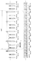
図17は、上記GOPの構成例を説明するための図であり、連続する複数のフレームF(k-5)〜F(k+12)と、各フレームに対応する符号化データD(k-5)〜D(k+12)とを対比して示している。なお、kは任意の整数である。
【0016】
ここでは、BフレームF(k-2)からPフレームF(k+9)での12のフレームによって、1つのGOPが構成されている。例えば、PフレームF(k+3)に対してはIフレームF(k)を参照フレームとしてフレーム間予測符号化処理が施される。また、PフレームF(k+6)に対しては、PフレームF(k+3)を参照フレームとしてフレーム間予測符号化処理が施される。また、BフレームF(k+1)及びF(k+2)に対しては、IフレームF(k)及びPフレームF(k+3)を参照フレームとしてフレーム間予測符号化処理が施される。
【0017】
上記符号化処理により得られた各フレームに対応する符号化データに対しては、復号化処理の際に使用されるメモリの容量を削減するため、該符号化データの配列を、各フレームの画像を表示する順番に従った配列から各フレームの復号化処理を行う順番に従った配列に変更する処理(配列変更処理)が施される。具体的には、上記GOPに対応する符号化データに上記配列変更処理を施して得られる符号化データでは、図17に示すように、IフレームF(k)の符号化データD(k)が該GOP対応の符号化データの先頭に位置し、その後に、BフレームF(k-2)の符号化データD(k-2)、BフレームF(k-1)の符号化データD(k-1)、PフレームF(k+3)の符号化データD(k+3)が順に続いている。
そして、上記GOP対応の符号化データは、上記配列変更処理後の順序で記録媒体に記録され、あるいは伝送媒体を介して伝送される。
【0018】
MPEG規格に準拠したビデオストリーム(ビデオ信号の符号化処理により得られる符号化データ)のヘッダ情報には、ビデオ解像度情報として、水平及び垂直画面サイズ,フレーム周波数,及びアスペクト比に関する情報が含まれる。また、上記ヘッダ情報には、上記ビデオストリームがインターレース信号とプログレッシブ信号のいずれに対応するものであるかを認識する情報も含まれる。
【0019】
DVDに関する規格では、1つ以上のGOPに対応しかつ0.4秒以上1.0秒以下の表示時間に相当する符号化データが、ビデオオブジェクトユニット(VOBU)(第3のデータ単位)として定義されており、上記VOBは、複数のVOBUから構成されている。
【0020】
また、上記VOBUは、上記第1のデータ単位であるパックを複数含んでおり、VOBUの先頭位置とパックの先頭位置とは一致している。また、VOBUの先頭部には、再生制御情報(PCI)、データサーチ情報(DSI)といった情報を含むナビゲーションパックと呼ばれるパックが配置されている。
【0021】
現在、テレビ放送の分野では、CS(communication satellite)放送が先駆けてデジタル化されているが、スタンダードテレビ信号のデジタル放送に続いて、ハイビジョンテレビ信号のデジタル放送も開始される。したがって、同じ放送系列にてスタンダードテレビ信号とハイビジョンテレビ信号とが混在する場合、また、同じ放送系列にてインターレース信号とプログレッシブ信号とが混在する場合が想定される。このような場合、同じ放送系列にて放送されるテレビ信号のビデオ解像度が、番組の切り替わりの際などに変化することとなる。
【0022】
また、このようなデジタルテレビ放送では、ビデオストリームとオーディオストリームはMPEG規格にしたがって多重化されて、トランスポートストリームとして送信される。
【0023】
一方、上記ビデオストリーム及びオーディオストリームをDVDに記録する際には、特殊再生機能を持たせるために、上記ビデオストリーム及びオーディオストリームを含むトランスポートストリームはプログラムストリームに変換され、このプログラムストリームがDVDに記録される。したがって、デジタルテレビ放送信号を受信してオーディオビデオストリームをDVDに記録するには、オーディオビデオストリームをトランスポートストリームからプログラムストリームに変換(TS/PS)する必要があり、このようなストリームの変換に関する技術はすでに開発されている。例えば、特開平11−45512号公報(株式会社日立製作所)には、TS/PS変換、つまりトランスポートストリームをプログラムストリームに変換する技術が開示されている。
【0024】
そこで、以下、上記プログラムストリームを光ディスクなどの記録媒体に記録するためのレコーディング規格について詳しく説明する。
まず、図18は、上記レコーディング規格に基づく記録データのフォーマットを説明するための図であり、ビデオ属性情報(V_ATR)10d1の詳しい内容を示している。
【0025】
記録データ10は、上記レコーディング規格に準拠したレコーダにより記録媒体に記録されたデータであり、この記録データ10は、ビデオマネージャ(VMG)10aと、3つのビデオオブジェクト,つまりビデオオブジェクト(1)(VOB(1))10a1,ビデオオブジェクト(2)(VOB(2))10a2,ビデオオブジェクト(3)(VOB(3))10a3とから構成されている。上記VOB(1)10a1〜VOB(3)10a3にはオーディオビデオストリームが含まれており、上記VMG10aには、各VOBの管理情報が含まれている。
【0026】
ここで、上記記録データ10は1つのテレビ放送番組に対応するものである。また、この記録データ10は、ユーザがこの番組のオーディオビデオストリームの記録中に2回の一時停止(ポーズ)操作を行ったことにより、上記レコーディング規格に従って3つのVOBに区分されて記録されている。つまりVOB(1)10a1とVOB(2)10a2の境界位置が第1回目のポーズ位置に対応し、VOB(2)10a2とVOB(3)10a3の境界位置が第2回目のポーズ位置に対応している。言い換えると、DVDのレコーディング規格に基づく記録処理では、オーディオビデオストリームの記録処理を一時停止すると、一時停止位置の前後のストリームは別々のVOBとして記録媒体に記録されることとなる。
【0027】
上述したように上記VMG10aは、記録された各VOBの管理情報であり、ビデオマネージャ情報(VMGI)10b1及びオーディオビデオファイル情報テーブル(AVFIT)10b2から構成されている。VMGI10b1には、サーチ情報として、各VOBが記録媒体に記録された時間(記録時間)、及び各VOBに対応する記録媒体における記録領域のアドレス(記録アドレス)に関する情報が含まれている。
【0028】
また、上記AVFIT10b2には、オーディオビデオファイルテーブル情報(AVFITI)10cと、上記記録されているVOBの個数と同じ個数のビデオオブジェクトストリーム情報(VOB_STI),つまりVOB_STI(1)10c1,VOB_STI(2)10c2,VOB_STI(3)10c3が含まれている。上記AVFITI10cには、記録されたVOBの個数情報などが含まれる。また上記各VOB_STI10c1〜10c3には、対応するVOBの属性情報が記述されており、例えば、VOB_STI(1)10c1は、ビデオ属性情報(V_ATR)10d1及びオーディオ属性情報(A_ATR)10d2からなる。
【0029】
以下まず、ビデオ属性情報(V_ATR)10d1について詳しく説明する。
上記V_ATR10d1には、圧縮モード(compression mode)情報10e1,水平解像度(H_Video resolution)情報10e2、垂直解像度(V_Video resolution)情報10e3、フレーム周波数(Frame frequency)情報10e4、テレビシステム(TV System)情報10e5、アスペクトレシオ(Aspect ratio)情報10e6が含まれる。
【0030】
ここで、上記圧縮モード情報10e1は、各VOBのビデオストリームが、MPEG−1の符号化方式とMPEG−2の符号化方式のいずれであるかを認識するための情報である。
【0031】
水平解像度情報10e2には、各VOBに対応する水平方向の画面サイズを識別するための情報が記述されている。具体的には、水平方向の画素数として、352、480、544、704、720、1440、1920などの値が記述されている。
【0032】
垂直解像度情報10e3には、各VOBに対応する垂直方向の画面サイズを識別するための情報が記述されている。具体的には、走査線のライン数として、240、480、576、720、1080などの値が記述されている。
【0033】
フレーム周波数情報10e4は、各VOBに対応するフレーム周波数を識別するための情報であり、例えば、24、29.97、30、25、50、60Hzなどの周波数情報である。
【0034】
テレビシステム情報10e5は、各VOBに対応するビデオ信号が、インターレース信号であるかあるいはプログレシップ信号であるかを識別するための情報である。
【0035】
アスペクトレシオ情報10e6は、各VOBに対応するビデオ信号のアスペクト比を識別するための情報であり、例えば、アスペクト比の値(4:3あるいは16:9)、レターボックスの種類などを示す情報である。
【0036】
なお、図18では、V_ATR10d1として、圧縮モード情報10e1,水平解像度情報10e2、垂直解像度情報10e3、フレーム周波数情報10e4、テレビシステム情報10e5、アスペクトレシオ情報10e6を含むものを示したが、図19に示すように、上記V_ATR10d1は、これらの情報10e1〜10e6に加えて、字幕データ情報(Line21_switch)10e7を含むものであってもよい。この字幕データ情報10e7は、第1フィールドのビデオ信号及び第2フィールドのビデオ信号の各々にLine21データが含まれているか否かを識別するための情報である。なお、Line21データ(Closed Caption Data)は、ビデオ信号の21ライン目に相当する部分に重畳される字幕データである。
【0037】
次に、上記オーディオ属性情報(A_ATR)10d2について詳しく説明する。
図20は、上記記録データのフォーマットを説明するための図であり、オーディオ属性情報(A_ATR)10d2の詳しい内容を示している。
【0038】
このA_ATR10d2には、各VOBに対応するオーディオ信号の属性を識別するための情報として、符号化方式(Codeing Mode)情報10f1,量子化情報(Quantization)10f2,ダイナミックレンジ制御情報(DRC)10f3,サンプリング周波数情報(fs)10f4,オーディオチャンネル数情報(Number of Audio channels)10f5,オーディオビットレート情報(Bitrate)10f6が含まれている。
【0039】
ここで、符号化方式(Codeing Mode)情報10f1は、各VOBに対応するオーディオストリームの種類を識別するための情報であり、例えば、オーディオストリームが、Dolby AC3方式,MPEG−1方式,MPEG−2方式,Linear PCMなどのいずれの方式に対応するかを示している。
【0040】
量子化情報10f2は、各VOBに対応するオーディオストリームがLinear PCM(Pulse Code Modulation)が施されたものである場合に、Linear PCMの際の量子化ビット数(16bit,20bit,24bit等)を識別するための情報である。
【0041】
ダイナミックレンジ制御情報10f3は、各VOBに対応するオーディオストリームに、MPEG−1あるいはMPEG−2の符号化処理におけるダイナミックレンジ制御データ(Dynamic range control data)が存在するか否かを識別するための情報である。
【0042】
サンプリング周波数情報10f4は、各VOBに対応するオーディオストリームのサンプリング周波数(48kHz,96kHzなど)を識別するための情報である。
【0043】
オーディオチャンネル数情報10f5は、各VOBに対応するオーディオストリームから得られる再生オーディオ信号のチャネル数(1ch(mono),2ch(stereo), 2ch(dual mono),3ch,4ch,5ch,6ch,7ch,8chなど)を識別するための情報である。
【0044】
オーディオビットレート情報(Bitrate)10f6は、各VOBに対応するオーディオストリームのビットレート(64kbps,89kbps,112kbps,128kbps,160kbps,192kbps,224kbps,256kbps,320kbps,384kbps,448kbps,768kbps,1536kbps)を識別するための情報である。
【0045】
上記のように記録媒体(光ディスク)に記録されている記録データからVMG10aを読み出すことにより、各VOBのオーディオビデオストリームの記録時間及びその記録アドレス、さらに各VOBの属性情報などを認識することができる。
【0046】
次に、記録データ10におけるVOBの構成について説明する。
図21及び図22は、上記記録データ10におけるVOBの構成を説明するための図であり、図21(a)及び図22(a)は、記録データ10のVOB(1)10a1の詳細な構成を示している。
【0047】
上記VOB(1)10a1は、いくつかのビデオオブジェクトユニット(VOBU)(ここでは、VOBU(1)10g1,VOBU(2)10g2,VOBU(3)10g3,VOBU(4)10g4,・・・,VOBU(n)10gn)から構成されている。
【0048】
また、1つのVOBUには、0.4〜1.0秒の表示時間に相当する、1以上のGOPに対応するオーディオビデオストリームが含まれている。例えば、VOBU(1)10g1は、複数のビデオパック(V_PCK)10h(1),10h(2) ,10h(3),・・・,10h(r)と、複数のオーディオパック(A_PCK)10i(1),10i(2) ,・・・,10i(s)とからなる。上記ビデオパック及びオーディオパックはそれぞれ所定のデータサイズを有するものであり、ここでは、上記ビデオパック及びオーディオパックのデータサイズは2048バイトとしている。
【0049】
図21(b)は、VOBU(1)10g1を構成するパックのうちのビデオパック10h(1)〜10h(8)と、GOPを構成する各フレームのストリームとの対応関係を示している。
【0050】
ここでVOBU(1)10g1は、1つのGOPに対応するビデオストリームを含んでいる。具体的には上記VOBU(1)10g1に含まれるビデオストリームは、Iフレームの符号化データDv1,Bフレームの符号化データDv2及びDv3,Pフレームの符号化データDv4,Bフレームの符号化データDv5及びDv6,Pフレームの符号化データDv7,Bフレームの符号化データDv8及びDv9,並びにパディングデータDpudから構成される。
【0051】
ここで、各VOBUは、2048バイトのビデオパック及びオーディオパックによって構成されているため、VOBUのデータサイズは2048バイトの整数倍のサイズにしなくてはならない。そこで、1つのGOPのビデオストリームに対してパディングデータDpudを付加することにより、VOBUに含まれるビデオストリームのデータサイズが、2048バイトの整数倍と一致するようにしている。
【0052】
また、図22(b)は、VOBU(1)10g1を構成するパックのうちのオーディオパック10i(1)〜10i(4)と、各オーディオフレームのストリームとの対応関係を示している。
【0053】
上記VOBU(1)10g1は、1つのGOPに対応するオーディオストリームを含んでいる。具体的には上記VOBU(1)10g1に含まれるオーディオストリームは、オーディオフレームDa1〜Da8の符号化データと、各オーディオパック(A_PCK)10i(1) 〜10i(4)に対応するパディングデータDpud1〜Dpud4とから構成されている。つまり、上記A_PCK10i(1)には、オーディオフレームDa1,Da2の符号化データとパディングデータDpud1が含まれ、A_PCK10i(2)には、オーディオフレームDa3,Da4の符号化データとパディングデータDpud2が含まれ、A_PCK10i(3)には、オーディオフレームDa5,Da6の符号化データとパディングデータDpud3が含まれ、A_PCK10i(4)には、オーディオフレームDa7,Da8の符号化データとパディングデータDpud4が含まれている。
【0054】
このように、1つのA_PCK10i(s)のオーディオストリームを、2つのオーディオフレームの符号化データとパディングデータとから構成することにより、VOBUに含まれるオーディオストリームのデータサイズが、2048バイトの整数倍と一致するようにしている。
【0055】
なお、図21(b)及び図22(b)では、VOB10a1及びVOBU(1)10g1の構成についてのみ詳細に示しているが、上記VOB10a1以外のVOB10a2及び10a3、並びに、VOBU(1)10g1以外のVOBU(2)10g2〜VOBU(n)10gnについてもそれぞれ、VOB10a1及びVOBU(1)10g1と同様な構成となっている。
【0056】
このように、VOBUを、所定のデータサイズ(2048バイト)のデータ単位で区分したデータ構造とすることにより、VOBUに対するアドレス管理が単純化され、記録媒体に対するVOBU単位でのデータのアクセスが容易となる。
【0057】
【発明が解決しようとする課題】
ところが、従来の記録装置では通常オーディオビデオストリームは1つのVOBとして記録され、その属性の管理がオーディオビデオストリーム全体としてまとめて行われることとなる。このため、以下のような種々の問題があった。
【0058】
以下これらの問題について詳述する。
従来の記録装置では、オーディオビデオストリームの記録する際、オーディオビデオストリームの記録を開始してからその記録を終了するまでの間に記録装置に入力されたストリームは、1つのVOBとして記録媒体に記録される。但し、上記ストリームの記録の途中で、記録動作を一時停止した場合には、一時停止前に入力されたストリームと、一時停止後に入力されたストリームとは、別のVOBとして記録媒体に記録される。また、その他の要因より、オーディオビデオストリームが複数のVOBとして記録される場合がある。
【0059】
言いかえると、従来の記録装置では、通常、1つの番組に対応するオーディオビデオストリームは、1つのVOBとして記録媒体に記録される。また、上記ストリームの記録中に、一時停止操作により、該ストリームにおける、CM(コマーシャル)などに相当する部分が記録されないようにした場合には、1つの番組に対応するオーディオビデオストリームは、複数の異なるVOBとして記録されることとなる。
【0060】
ところで、デジタル放送信号は、通常はMPEGストリーム(MPEG規格に対応したオーディオビデオストリーム)として記録装置に入力されるため、デジタル放送信号を受信して記録する場合は、アナログ放送信号を受信して記録する場合とは異なり、画像のシーンによって、記録途中で、ビデオ解像度などのビデオ属性が変化する。例えば、水平方向の解像度が、720画素から352画素に変化する場合などがある。
【0061】
また、スタンダードテレビ放送の番組とハイビジョンテレビ放送の番組とを続けて録画した場合には、これらの番組に対応する記録データの属性であるアスペクトレシオは、2つの番組の切り替わり点で、4:3から16:9に変化することとなる。
【0062】
このような場合には、1つのVOBとして、その属性が異なる2つのオーディオビデオストリームが記録されることとなり、記録媒体に記録されたストリームのビデオ属性の管理が困難になるという問題があった。
【0063】
また、記録媒体に記録されているオーディオビデオストリームを再生する再生処理では、ビデオストリーム(符号化データ)の復号化処理がビデオ解像度をパラメータとして行われるため、ビデオ属性としてのビデオ解像度の管理が不完全であり、ビデオ解像度の変化を、上記復号化処理を行うデコーダに通知できない場合にはビデオストリームに対する復号化処理が破綻するという問題もある。
【0064】
さらに、オーディオビデオストリームの記録位置は、VOBを構成する各VOBUに対応するアドレスにより管理されているため、VOBUに含まれるストリームの、ビデオ解像度の変化が発生した位置に対して、直接アクセスすることができず、ビデオ解像度の変化に基づいた番組の頭だしなどを高速で行うことができないという問題もあった。
【0065】
また、上記VOBUに含まれる符号化データは、パック化により、一定のデータサイズ(2048バイト)を有するデータ単位(パック)毎に区分され、各パックはその先頭データの記録位置を示すアドレスにより管理されているが、ストリームにおけるビデオ解像度の変化点に対応する位置と、アクセスの単位でもあるパックの先頭位置とは必ずしも一致しておらず、このため、パックの記録位置を示すアドレスを用いても、ストリームにおける、ビデオ解像度の変化位置にアクセスすることはできないという問題があった。
【0066】
また、MPEG−2符号化方式によりビデオ信号を符号化する場合には、各フレームに対する符号化モードが所定の規則に基づいて決定され、決定された符号化モードに応じて、少なくとも1つのIフレーム,複数のPフレーム及び複数のBフレームからなるGOPが構成されるよう符号化処理が行われるため、ビデオ解像度が変化すると、1つのGOPを構成するフレームの間でビデオ解像度が異なる場合が生じ、MPEG−2の規格に対応したストリームが生成できないという問題があった。
【0067】
さらに、MPEG符号化方式では、処理対象となる現フレームのビデオ信号を、処理済みの参照フレームのビデオ信号を参照して符号化するフレーム間予測符号化処理が行われるため、ビデオ解像度が変化すると、現フレームと参照フレームの間での解像度の違いが発生し、フレーム間予測符号化処理が破綻するという問題もあった。
【0068】
また、ビデオアスペクト比が変化するテレビ信号を符号化して得られる符号化データを記録する場合にも、上記のようにビデオ解像度が変化する場合と同様、以下のような問題が生ずる。
【0069】
つまり、ビデオアスペクト比の変化により、記録されたオーディオビデオストリーム(符号化データ)に対するビデオ属性の管理が困難になる。また、再生処理では、ビデオアスペクト比の変化に起因して、符号化データの復号化処理が破綻する。さらに、ビデオストリームの、ビデオアスペクト比が変化した部分に対する高速アクセスが不可能である。
【0070】
さらに、MPEG符号化方式では、ビデオアスペクト比が変化すると、上記のようにビデオ解像度が変化する場合と同様、MPEG−2の規格に対応したストリームが生成できない、フレーム間予測符号化処理が破綻するという問題が生ずる。
【0071】
なお、ビデオ解像度やビデオアスペクト比だけでなく、符号化方式などのその他の複数のビデオ属性をもつビデオ信号では、記録されたビデオストリームの、上記ビデオ属性の変化が発生した位置にアクセスすることができないという問題がある。
【0072】
また、ビデオ信号だけでなくこの信号に付随するオーディオ信号も含まれているオーディオビデオ信号では、このオーディオビデオ信号に対応する、記録された符号化データにおける、オーディオ信号の符号化方式,チャンネル数,ビットレートなどのオーディオ属性が変化した位置に対するアクセスも不可能であるという問題がある。
【0073】
本発明は上記のような問題点に鑑みてなされたもので、符号化方式,ビデオ解像度,ビデオアスペクト比等のビデオ属性と、符号化方式,チャンネル数,ビットレートなどのオーディオ属性の少なくとも一方の属性が変化するテレビ信号に対応する符号化データを、その属性の変化が発生した部分に高速にアクセスできるよう記録する記録装置を提供することを目的とする。
【0074】
本発明は、上記ビデオ属性及びオーディオ属性の少なくとも一方の属性が変化するテレビ信号に対応する符号化データを、その復号化処理が良好に行われるよう管理しつつ記録媒体に記録することができる記録装置を提供することを目的とする。
【0075】
本発明は、符号化方式,ビデオ解像度,ビデオアスペクト比等のビデオ属性が変化するビデオ信号を、MPEG等の符号化方式に従って符号化することができる符号化装置を得ることを目的とする。
【0076】
【課題を解決するための手段】
この発明に係る記録装置は、オーディオ信号及びビデオ信号を含むオーディオビデオ信号を符号化して得られるオーディオビデオストリームを記録媒体に記録する装置であって、上記オーディオビデオストリームに基づいて、上記ビデオ信号及びオーディオ信号の少なくとも一方の信号に関する属性を検出し、該属性を示す属性データを出力する属性検出部と、上記属性データに基づいて、上記属性が変化した時点に対応する、上記記録媒体に記録されるオーディオビデオストリームの記録位置、あるいは上記属性変化時点に対応する、基準時刻に対するオーディオビデオストリームの記録時刻を検出し、該記録位置あるいは記録時刻を示す属性変化情報を出力する情報生成部と、上記属性データ及び上記属性変化情報を上記記録媒体に記録する記録部とを備えたものである。
【0077】
この発明は、上記記録装置において、上記属性検出部を、上記ビデオ信号に関するビデオ属性及びオーディオ信号に関するオーディオ属性を検出し、それぞれの属性を示す属性データを出力するものとし、上記記録部を、上記ビデオ属性を示す属性データおよび上記オーディオ属性を示す属性データを、それぞれ上記記録媒体の所定の記録領域に記録するものとしたものである。
【0078】
この発明は、上記記録装置において、上記属性検出部を、上記ビデオ信号に関する属性として、該ビデオ信号のビデオ解像度を検出し、該解像度を示すビデオ解像度データを出力するものとし、上記情報生成部を、上記ビデオ解像度データに基づいて、上記ビデオ解像度が変化した時点に対応する、上記記録媒体に記録されるストリームの記録位置、あるいは該ビデオ解像度の変化時点に対応する、基準時刻に対するストリームの記録時刻を検出し、該記録位置あるいは記録時刻を示す解像度変化情報を出力するものとし、上記記録部を、上記ビデオ解像度データ及び上記解像度変化情報を上記記録媒体に記録するものとしたものである。
【0079】
この発明は、上記記録装置において、上記属性検出部を、上記ビデオ信号に関する属性として、該ビデオ信号のアスペクトレシオを検出し、該アスペクトレシオを示すアスペクトレシオデータを出力するものとし、上記情報生成部を、上記アスペクトレシオデータに基づいて、上記アスペクトレシオが変化した時点に対応する、上記記録媒体に記録されるストリームの記録位置、あるいは該アスペクトレシオの変化時点に対応する、基準時刻に対するストリームの記録時刻を検出し、該記録位置あるいは記録時刻を示すアスペクトレシオ変化情報を出力するものとし、上記記録部を、上記アスペクトレシオ及び上記アスペクトレシオ変化情報を上記記録媒体に記録するものとしたものである。
【0080】
この発明は、オーディオ信号及びビデオ信号を含むオーディオビデオ信号を符号化して得られるオーディオビデオストリームを記録媒体に記録する装置であって、上記オーディオビデオストリームを所定サイズ毎にデータ単位としてのパックが形成されるよう区分するパック化処理を行って、各パックに対応するオーディオビデオストリームをパックデータとして出力するパック化処理部と、上記パックデータを、上記記録媒体に対するアクセス単位として該記録媒体に記録する記録部と、上記オーディオビデオストリームに基づいて、上記ビデオ信号及びオーディオ信号の少なくとも一方の信号に関する属性を検出し、該属性を示す属性データを出力する属性検出部とを備え、上記パック化処理部を、上記属性データに基づいて、上記オーディオビデオストリームにおける上記属性が変化した位置が、上記パックの先頭に位置するよう上記パック化処理を行うものとしたものである。
【0081】
この発明は、上記記録装置において、上記属性検出部を、上記オーディオビデオストリームに基づいて、上記ビデオ信号に関するビデオ属性及びオーディオ信号に関するオーディオ属性を検出し、上記ビデオ属性を示すビデオ属性データおよび上記オーディオ属性を示すオーディオ属性データを出力するものとし、上記記録部を、上記ビデオ属性を示すビデオ属性データおよび上記オーディオ属性を示すオーディオ属性データを、それぞれ上記記録媒体の所定の記録領域に記録するものとしたものである。
【0082】
この発明は、上記記録装置において、上記属性データに基づいて、上記オーディオ属性及びビデオ属性の少なくとも一方の属性が変化した時点に対応する、上記記録媒体に記録されるオーディオビデオストリームの記録位置、あるいは該属性変化時点に対応する、基準時刻に対するオーディオビデオストリームの記録時刻を検出し、該記録位置あるいは記録時刻を示す属性変化情報を出力する情報生成部を備え、上記属性変化情報を上記記録媒体に記録するものである。
【0083】
この発明は、上記記録装置において、上記属性検出部を、上記ビデオ信号に関する属性として、上記ビデオ信号のビデオ解像度を検出し、該解像度を示すビデオ解像度データを出力するものとし、上記パック化処理部を、上記ビデオ解像度データに基づいて、上記ビデオストリームにおける上記ビデオ解像度が変化した位置が、上記パックの先頭に位置するよう上記パック化処理を行うものとしたものである。
【0084】
この発明は、上記記録装置において、上記属性検出部を、上記ビデオ信号に関する属性として、上記ビデオ信号のアスペクトレシオを検出し、該アスペクトレシオを示すアスペクトレシオデータを出力するものとし、上記パック化処理部を、上記アスペクトレシオデータに基づいて、上記ビデオストリームにおける上記アスペクトレシオが変化した位置が、上記パックの先頭に位置するよう上記パック化処理を行うものとしたものである。
【0085】
この発明は、オーディオ信号及びビデオ信号を含むオーディオビデオ信号を符号化して得られるオーディオビデオストリームを記録媒体に記録する装置であって、上記オーディオビデオストリームを、該ストリームを管理するための管理単位毎に区分し、該ストリームの各管理単位に対応する部分をビデオオブジェクトデータとして出力するビデオオブジェクト構成器と、上記各ビデオオブジェクトデータを管理するための管理情報を上記記録媒体に記録する記録部と、上記オーディオビデオストリームに基づいて、上記ビデオ信号及びオーディオ信号の少なくとも一方の信号に関する属性を検出し、該属性を示す属性データを出力する属性検出部とを備え、上記ビデオオブジェクト構成器を、上記属性データに基づいて、上記属性が変化したとき、上記オーディオビデオストリームの、該属性の変化点より前の部分と、該オーディオビデオストリームの、該属性の変化点以降の部分とが別々のビデオオブジェクトデータとして出力されるよう上記オーディオビデオストリームの区分を行うものとしたものである。
【0086】
この発明は、上記記録装置において、上記管理情報には、各ビデオオブジェクトデータの、記録媒体に対する記録位置、あるいは、各ビデオオブジェクトデータの、基準時刻に対する記録時刻に関する情報が含まれているものである。
【0087】
この発明は、上記記録装置において、上記属性検出部を、上記オーディオビデオストリームに基づいて、上記ビデオ信号に関するビデオ属性及びオーディオ信号に関するオーディオ属性を検出し、上記ビデオ属性を示すビデオ属性データおよび上記オーディオ属性を示すオーディオ属性データを出力するものとし、上記管理情報を、上記ビデオ属性を示すビデオ属性情報および上記オーディオ属性を示すオーディオ属性情報を含む情報としたものである。
【0088】
この発明は、上記記録装置において、上記属性検出部を、上記ビデオ信号に関する属性として、上記ビデオ信号のビデオ解像度を検出し、該解像度を示すビデオ解像度データを出力するものとし、上記ビデオオブジェクト構成器を、上記ビデオ解像度データに基づいて、上記ビデオ解像度が変化したとき、上記ビデオストリームの、上記ビデオ解像度の変化点より前の部分と、該ビデオストリームの、該ビデオ解像度の変化点以降の部分とが、別々のビデオオブジェクトデータとして出力されるよう上記ビデオストリームの区分を行うものとしたものである。
【0089】
この発明は、上記記録装置において、上記属性検出部を、上記ビデオ信号に関する属性として、上記ビデオ信号のアスペクトレシオを検出し、該アスペクトレシオを示すアスペクトレシオデータを出力するものとし、上記ビデオオブジェクト構成器を、上記アスペクトレシオデータに基づいて、上記アスペクトレシオが変化したとき、上記ビデオストリームの、アスペクトレシオの変化点より前の部分と、上記ビデオストリームの、アスペクトレシオの変化点以降の部分とが、別々のビデオオブジェクトデータとして出力されるよう上記ビデオストリームの区分を行うものとしたものである。
【0090】
この発明は、ビデオ信号を符号化する装置であって、上記ビデオ信号に対するフレーム内符号化処理あるいはフレーム間符号化処理を、該フレーム内符号化処理が施されたフレームを少なくとも1つ含むフレーム群が構成され、かつ該フレーム群に対応するビデオストリームがランダムアクセス可能なストリーム単位として出力されるよう行うビデオ符号化部と、上記ビデオ信号に基づいてそのビデオ属性を検出し、該ビデオ属性を示すビデオ属性データを出力するビデオ属性検出器とを備え、上記ビデオ符号化部を、上記ビデオ属性が直前のフレームとは異なる特定フレームが、上記フレーム群の先頭フレームとなるよう上記フレーム群を構成するものとしたものである。
【0091】
この発明は、上記符号化装置において、上記ビデオ信号に付随したオーディオ信号に基づいてそのオーディオ属性を検出し、該オーディオ属性を示すオーディオ属性データを出力するオーディオ属性検出器を備え、上記ビデオ符号化部を、上記ビデオ属性あるいはオーディオ属性が直前のフレームとは異なる特定フレームが上記フレーム群の先頭フレームとなるよう上記フレーム群を構成するものとしたものである。
【0092】
この発明は、上記符号化装置において、上記ビデオストリームを所定サイズ毎にデータ単位としてのパックが形成されるよう区分するパック化処理を行って、各パックに対応するストリームをパックデータとして出力するパック化処理部を備え、上記パック化処理部を、上記ビデオストリームにおける上記ビデオ属性あるいはオーディオ属性が変化した位置が、上記パックの先頭に位置するよう上記パック化処理を行うものとしたものである。
【0093】
この発明は、上記符号化装置において、上記ビデオ符号化部を、上記特定フレームを含む特定フレーム群における各フレームに対する符号化処理を、上記特定フレーム群以前に符号化処理が施されたフレーム群におけるフレームに対応するビデオ信号を参照せずに行うものとしたものである。
【0094】
この発明は、上記符号化装置において、上記ビデオ属性検出部を、上記ビデオ信号に基づいて上記ビデオ属性として該ビデオ信号のビデオ解像度を検出し、該ビデオ解像度を示すビデオ解像度データを出力するものとし、上記ビデオ符号化部を、上記ビデオ解像度データに基づいて、上記ビデオ解像度が直前のフレームとは異なる特定フレームが、上記フレーム群の先頭フレームとなるよう上記フレーム群を構成するものとしたものである。
【0095】
この発明は、上記符号化装置において、上記ビデオストリームを所定サイズ毎にデータ単位としてのパックが形成されるよう区分するパック化処理を行って、各パックに対応するストリームをパックデータとして出力するパック化処理部を備え、上記パック化処理部を、上記ビデオストリームにおける上記ビデオ解像度が変化した位置が、上記パックの先頭に位置するよう上記パック化処理を行うものとしたものである。
【0096】
この発明は、上記符号化装置において、上記属性検出器を、上記ビデオ信号に基づいて、上記ビデオ属性として該ビデオ信号のアスペクトレシオを検出し、該アスペクトレシオを示すアスペクトレシオデータを出力するものとし、上記ビデオ符号化部を、上記アスペクトレシオデータに基づいて、上記アスペクトレシオが直前のフレームとは異なる特定フレームが、上記フレーム群の先頭フレームとなるよう上記フレーム群を構成するものとしたものである。
【0097】
この発明は、上記符号化装置において、上記ビデオストリームを所定サイズ毎にデータ単位としてのパックが形成されるよう区分するパック化処理を行って、各パックに対応するストリームをパックデータとして出力するパック化処理部を備え、上記パック化処理部を、上記ビデオストリームにおける上記アスペクトレシオが変化した位置が、上記パックの先頭に位置するよう上記パック化処理を行うものとしたものである。
【0098】
【発明の実施の形態】
以下、本発明の実施の形態について説明する。
【0099】
(実施の形態1)
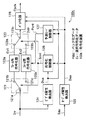
図1は本発明の実施の形態1による記録装置を説明するためのブロック図である。
この実施の形態1の記録装置100aは、デジタル放送信号Sbrを受信して、オーディオビデオストリームSavを出力する放送受信器102と、該オーディオビデオストリームSavをビデオ規格のフォーマットに従って記録形式のデータに変換して、VOBデータDvobを出力するVOB構成器103とを有している。
【0100】
ここで、上記放送受信器102は、伝送形式のストリーム(トランスポートストリーム)を記録形式のストリーム(プログラムストリーム)に変換するTS/PS変換機能を有しており、上記放送受信器102から出力されるオーディオビデオストリームSavは、プログラムストリームとなっている。また、上記放送受信器102とVOB構成器103の間には、オーディオビデオストリームSavに対して、一定サイズ(ここでは2Kバイト)を有する第1のデータ単位毎に区分するパック化処理を施すパック化器(図示せず)が設けられており、該パック化器からは、各データ区分(パック)に対応するデータ(PCKデータ)が順次VOB構成器103に出力されるようになっている。またこのパック化器は、上記PCKデータとして、オーディオストリームを格納したオーディオパック(A_PCK)と、ビデオストリームを格納したビデオパック(V_PCK)とを出力する構成となっている。なお、ここでは、PCKデータは2Kバイトの固定長データとしているが、PCKデータは可変長データとしてもよい。この場合には、各パックのヘッダにそのデータサイズが書きこまれることとなる。また、上記VOB構成器103は、上記パック化器からのPCKデータに基づいて、図21及び図22に示すように複数のパックからなる第3のデータ単位(VOBU)を形成し、さらに複数のVOBUからなる第2のデータ単位(VOB)を形成し、該VOBに対応するデータを、上記VOBデータDvobとして出力する構成となっている。
【0101】
上記記録装置100aは、上記オーディオビデオストリームSavを受け、これに含まれるビデオストリームのヘッダ情報の解析により、該ビデオストリームに対応するビデオ属性を検出し、該ビデオ属性を示すデータ(ビデオ属性データ)Dvaを出力するビデオ属性検出器107と、上記オーディオビデオストリームSavを受け、これに含まれるオーディオストリームのヘッダ情報の解析により該オーディオストリームに対応するオーディオ属性を検出し、該オーディオ属性を示すデータ(オーディオ属性データ)Daaを出力するオーディオ属性検出器109とを有している。
【0102】
ここで、上記ビデオ属性には、符号化方式のモード(例えば、MPEG−1方式あるいはMPEG−2方式など)、水平画面サイズ、垂直画面サイズ、フレーム周波数、画素サンプリング周波数、色信号成分フォーマット、アスペクトレシオ、レターボックス、ビットレート、走査モード(つまりインターレースあるいはプログレッシブ)のなどがある。上記ビデオ属性検出器107は、これらの属性を示す情報のうち少なくとも1つ以上の属性情報を検出する構成となっている。また、オーディオ属性には、符号化方式、チャンネル数、サンプリング周波数、量子化ビット数、ダイナミックレンジコントロール、ビットレートなどがあり、上記オーディオ属性検出器109は、これらの属性を示す情報のうち少なくとも一つ以上の属性情報を検出する構成となっている。
【0103】
上記記録装置100aは、上記記録媒体106の記録領域におけるデータを書き込む位置(書込みアドレス)を示す書込みアドレス情報Iwaを発生するシステムコントローラ111と、上記ビデオ属性データDaa,オーディオ属性情報Dva及びアドレス情報Iwaに基づいて、属性変化が発生した時点の書込みアドレスを示す特定アドレス情報Isaを出力するアドレス情報生成器108と、上記ビデオ属性データDva,オーディオ属性データDaa及び特定アドレス情報Isaに基づいて、各VOBに対応する管理情報であるVMG情報Dvmgを生成するVMG生成器110とを有している。このVMG生成器110は、オーディオビデオストリームSavのビデオ属性及びオーディオ属性の変化があった場合、上記VMG情報Dvmgとして、属性変化が発生した時点の書込みアドレスを示す特定アドレス情報Isaを含む情報を出力する構成となっている。
【0104】
上記記録装置100aは、上記VOB構成器103からのVOBデータDvob及びVMG生成器110からのVMG情報Dvmgに対して、誤り訂正符号の付加処理及び記録変調処理を施して、該VOBデータに対応する記録信号Sreを出力する記録信号処理器110と、該記録信号Sreを光ディスクなどの記録媒体106に書き込む記録ヘッド105とを有している。
なお、図1中、101は上記デジタル放送信号を受信するアンテナであり、このアンテナ101の出力は上記放送受信器102に入力されるようになっている。
【0105】
次に動作について説明する。
アンテナ101からの放送信号Sbrが放送受信器102に受信されると、該放送受信器102では、該放送信号Sbrに対する所定の処理によりオーディオビデオストリームSavが抽出される。このオーディオビデオストリームSavは、パック化器(図示せず),ビデオ属性検出器107及びオーディオ属性検出器109に出力される。なお、上記放送受信器102からは、上記オーディオビデオストリームSavが、該受信器102のTS/PS変換機能によりプログラムストリームとして出力される。
【0106】
そして上記パック化器では、オーディオビデオストリームSavに対してパック化処理が施され、該オーディオビデオストリームSavは、パック化処理により得られたPCKデータとして上記VOB構成器103に出力される。
【0107】
すると、VOB構成器103では、オーディオビデオストリーム(PCKデータ)SavはDVDのレコーディング規格のフォーマットに従ってVOBデータDvob(図21及び図22参照)に変換され、該VOBデータDvobは記録信号処理器104へ出力される。
【0108】
このVOBデータDvobは、上記記録信号処理器104にて誤り訂正符号の付加処理及び記録変調処理が施されて、該VOBデータDvobに対応する記録信号Sreが生成される。この記録信号Sreは、システムコントローラ111にて生成される書込みアドレス情報Iwaに従って、記録ヘッド105により光ディスク(記録媒体)106の所定の記録領域に書き込まれる。
【0109】
また、ビデオ属性検出器107では、上記オーディオビデオストリームSavに含まれるビデオストリームのヘッダ情報の解析により、該ビデオストリームに対応するビデオ属性が検出され、このビデオ属性を示すデータ(ビデオ属性データ)Dvaがアドレス情報生成器108及びVMG生成器110に出力される。
【0110】
一方、オーディオ属性検出器109では、上記オーディオビデオストリームSavに含まれるオーディオストリームのヘッダ情報の解析により、該オーディオストリームに対応するオーディオ属性が検出され、このオーディオ属性を示すデータ(オーディオ属性データ)Daaがアドレス情報生成器108及びVMG生成器110に出力される。
【0111】
該アドレス情報生成器108では、ビデオ属性及びオーディオ属性の少なくとも一方が変化したとき、上記書込みアドレス情報Iwa、ビデオ属性データDva及びオーディオ属性データDaaに基づいて、ビデオ属性あるいはオーディオ属性の変化が発生した時点の書込みアドレスを示す特定アドレス情報Isaが生成され、該特定アドレス情報IsaがVMG生成器110に出力される。
【0112】
このVMG生成器110では、上記ビデオ属性情報Dva,オーディオ属性情報Daa及び特定アドレス情報Isaに基づいて、上記各VOBに対応する管理情報であるVMG情報Dvmgが生成される。そして、このVMG情報Dvmgは、上記記録信号処理器104にて誤り訂正符号の付加処理及び記録変調処理が施されて、該VMG情報Dvmgに対応する記録信号Sreが生成される。この記録信号Sreは記録ヘッド105により光ディスク106に書き込まれる。なお、上記VMG情報Dvmgに対応する記録信号Sreは、VOBデータDvobに対応する記録信号Sreの記録媒体への記録が完了した後に、記録媒体の所定の記録領域に書き込まれる。このとき、上記特定アドレス情報Isaは、VMGI情報10b1に対応する記録領域に書き込まれる。また、ビデオ属性データDvaおよびオーディオ属性データDaaはVMG情報10a内のV_ATR10d1及びA_ATR10d2に記録される。
【0113】
このように本実施の形態1の記録装置100aでは、ビデオ属性を検出する検出器107と、オーディオ属性を検出する検出器109と、該両検出器107及び109の検出出力に基づいて、ビデオ属性あるいはオーディオ属性が変化した時点でのデータ書込みアドレスを示す特定アドレス情報Isaを生成するアドレス情報生成器108とを備え、該特定アドレス情報Isaを、各VOBの管理情報(VMG情報)10aを構成するVMGI10b1に対応する、光ディスク106の記録領域に書き込むようにしたので、光ディスク106に記録されているオーディオビデオストリームを再生する際には、上記VMG情報10aを読み出すことにより、オーディオビデオストリームにおける、ビデオ属性あるいはオーディオ属性が変化した部分に対応する記録位置を認識することができ、オーディオビデオストリームの再生時に、光ディスクにおける、ビデオ属性あるいはオーディオ属性変化が生じているストリームの記録位置に対して高速にアクセスすることが可能となる。
【0114】
なお、上記実施の形態1では、ビデオ属性あるいはオーディオ属性が変化した時点でのデータ書込みアドレスを示す特定アドレス情報Isaを記録媒体に記録するようにしているが、上記特定アドレス情報Isaに代えて、ビデオ属性あるいはオーディオ属性が変化した時点での、基準時刻に対する記録時刻を示す情報を記録媒体に記録するようにしてもよい。
【0115】
(実施の形態2)
図2は本発明の実施の形態2による記録装置を説明するためのブロック図である。
この実施の形態2の記録装置100bは、上記実施の形態1の記録装置100aのパック化器(図示せず)に代えて、上記パック化処理を行うとともに、オーディオ属性あるいはビデオ属性が変化したとき、属性変化前のストリームと属性変化後のストリームが1つのパック内に含まれることがないよう、作成中のパックには属性変化直前のストリームに続けてパディングデータを挿入するパック化器112と、上記ビデオ属性データDva,オーディオ属性データDaa,及びパック化器112における内部信号Sopに基づいて、上記パディングデータのサイズを算出し、該サイズを示すデータ(サイズデータ)Dpsを上記パック化器112に出力するパディングサイズ生成器113とを備えている。なお、上記パディングデータはスタッフィングデータとも呼ばれている。
【0116】
そして、この実施の形態2の記録装置100bのその他の構成は、実施の形態1の記録装置100aと同一となっている。
なお、103bは、この実施の形態2の記録装置100bにおけるVOB構成器であり、このVOB構成器103bは、実施の形態1のVOB構成器103と同様、上記パック化器112からのPCKデータDpckをビデオ規格のフォーマットに従ってVOBデータDvobに変換する構成となっている。
【0117】
次に動作について説明する。
この実施の形態2の記録装置100bでは、放送受信器102からのオーディオビデオストリームSavはパック化器112にて、一定データサイズを有するデータ単位(第1のデータ単位)毎に区分されて、各データ区分(パック)に対応するPCKデータDpckがVOB構成器103bに出力される。このとき、オーディオストリームはオーディオPCKデータ(以下単にオーディオパックともいう。)として、ビデオストリームはビデオPCKデータ(以下単にビデオパックともいう。)として上記VOB構成器103bに出力される。
【0118】
すると、該VOB構成器103bでは、所定の表示時間に対応する個数のオーディオパック及びビデオパックがVOBU(第3のデータ単位)としてまとめられ、記録開始から記録終了までの間に入力されたオーディオビデオストリームSavに相当する、複数のVOBUからなるVOBデータDvobが生成される。
【0119】
そして、このVOBデータDvobは記録信号処理器104にて記録信号Sreに変換され、光ヘッド105により書込みアドレスIwaに基づいて記録媒体106に記録される。
【0120】
また、ビデオ属性検出器107ではビデオ属性の検出によりビデオ属性データDvaが出力され、オーディオ属性検出器109ではオーディオ属性の検出によりオーディオ属性データDaaが出力される。
【0121】
アドレス情報生成器108では、ビデオ属性データDva,オーディオ属性データDaa,及び書込みアドレス情報Iwaに基づいて、オーディオ属性あるいはビデオ属性が変化した時点での書込みアドレスを示す特定アドレス情報Isaが出力される。
【0122】
また、パディングサイズ生成器113では、ビデオ属性データDva,オーディオ属性データDaa,及びパック化器112でのパック処理状態を示す内部信号Sopを受け、ビデオ属性あるいはオーディオ属性が変化したときには、パディングデータのサイズが算出され、該データサイズを示す情報(サイズ情報)Dpsが出力される。具体的には、パック化器112にて所定のパックにストリーム(つまりビデオストリームあるいはオーディオストリーム)を格納している状態で属性変化が検出されると、この時点でのパックの空きデータサイズが、上記パディングデータのサイズとして算出される。
【0123】
そして、上記データサイズ情報Dpsがパック化器112に入力されると、その時点でのパックの空き部分には、ストリームにおける、属性変化が発生した位置以降の部分に代えて、パディングデータが、サイズ情報Dpsが示すデータ量だけ挿入される。これにより所定のパックの作成中に属性変化が発生しても、該所定のパックに、属性変化前のストリームデータと属性変化後のストリームが含まれることはない。言い換えると、属性変化が発生したときには、属性変化前のストリームと属性変化後のストリームとは、隣接する別々のパックに格納されるとこととなり、属性変化後のストリームデータは、上記所定のパックに続く後続パックにその先頭から格納されることとなる。
【0124】
そして、この記録装置100bにおけるその他の動作は、上記実施の形態1の記録装置100aと同様に行われ、各VOBに対応するVMG情報Dvmgに対応する記録信号Sreが記録媒体106に記録される。
【0125】
このように本実施の形態2の記録装置100bでは、実施の形態1のパック化器に代えて、オーディオ属性あるいはビデオ属性が変化したとき、パックにパディングデータを挿入するパック化器112と、上記パディングデータのサイズを算出するディングサイズ生成器113とを備え、属性変化が発生したとき、作成中のパックには、属性変化後のストリームに代えてパディングデータを挿入するようにしたので、ストリームは属性変化後のストリームの先頭とパックの先頭とが一致するよう記録されることとなる。
【0126】
このため、光ディスク106に記録されたオーディオビデオストリームを再生する際には、上記VMG情報10aを読み出すことにより、パック単位で記録アドレスが管理されているオーディオビデオストリームにおける、ビデオ属性あるいはオーディオ属性が変化した部分に対応する記録位置を認識することができ、オーディオビデオストリームの再生時に、光ディスクにおける、属性変化が生じているストリームの記録位置に高速にアクセスすることが可能となる。
【0127】
なお、上記実施の形態2では、ストリームの所定位置と、パックの先頭位置とを、パックにパディングデータを挿入することにより一致させるようにしているが、ストリームの所定位置とパックの先頭位置とを一致させる方法は、これに限らず、例えば、パックヘッダ等に記載されるパックデータのサイズ情報を変更するようにしてもよい。
【0128】
また、上記実施の形態1,2では、ビデオ属性及びオーディオ属性の両方を検出し、これらの変化に応じて特定アドレス情報Isaを発生するようにしているが、上記ビデオ属性及びオーディオ属性の一方のみを検出し、検出した属性の変化に応じて特定アドレス情報Isaを発生するようにしてもよい。
【0129】
(実施の形態3)
図3は本発明の実施の形態3による記録装置を説明するためのブロック図である。
この実施の形態3の記録装置100cは、上記実施の形態1の記録装置100aにおけるアドレス情報生成器108及びVMG生成器110に代えて、各属性検出器107,109からのビデオ属性データDva,オーディオ属性データDaaに基づいて、VOBの管理情報であるVMG情報Dvmgを生成するVMG生成器110cを備えている。
【0130】
さらに、上記記録装置100cは、上記記録装置100aにおけるVOB構成器103に代えて、上記ビデオ属性データDva及びオーディオ属性データDaaに基づいて、オーディオ属性及びビデオ属性のいずれかが変化したとき、属性変化前のストリームと属性変化後のストリームが、別々のVOBデータとして区分されるよう、VOBデータを生成するVOB構成器103cを備えている。
そしてこの実施の形態3の記録装置100cにおけるその他の構成は、上記実施の形態1の記録装置100aにおけるものと同一である。
【0131】
次に動作について説明する。
この実施の形態3では、アンテナ101からの放送信号Sbrが放送受信器102に受信され、該受信器102からのオーディオビデオストリームSavが、VOB構成器103c,ビデオ属性検出器107及びオーディオ属性検出器109に入力されると、VOB構成器103cでは、オーディオビデオストリームSavは、DVDのレコーディング規格のフォーマットに従ってVOBデータDvob(図21及び図22参照)に変換される。このVOBデータDvobは、記録信号処理器104により記録信号Sreに変換され、さらに記録信号Sreは記録ヘッド105により光ディスク106に書き込まれる。
【0132】
また、ビデオ属性検出器107では、上記オーディオビデオストリームSavに基づいてビデオ属性が検出され、ビデオ属性データDvaがVOB構成器103c及びVMG生成器110に出力される。オーディオ属性検出器109では、上記オーディオビデオストリームSavに基づいてオーディオ属性が検出され、オーディオ属性データDaaがVOB構成器103c及びVMG生成器110に出力される。
【0133】
なお、上記受信器102,VOB構成器103c,記録信号処理器104,記録ヘッド105及び各属性検出器107,109の動作は、上記実施の形態1におけるものと全く同一である。
【0134】
そして、この実施の形態3では、上記オーディオビデオストリームSavの記録中にビデオ属性あるいはオーディオ属性が変化したときには、VOB構成器103cでは、属性変化前のストリームと属性変化後のストリームとが別々のVOBデータとなるよう、上記オーディオビデオストリームSavに対応するVOBデータDvobが形成される。
【0135】
上記VMG生成器110cでは、記録されたVOBデータに対応する管理情報であるVMG情報Dvmgが生成され、該VMG情報Dvmgは記録信号処理器104に出力される。この処理器104では、該VMG情報Dvmgに誤り訂正符号の付加処理及び記録変調処理が施されて、該VMG情報Dvmgに対応する記録信号Sreが生成される。該記録信号Sreは光ヘッド105により光ディスク106に記録される。
【0136】
なお、上記VMG情報Dvmgには、図18に示すように、各VOBデータに対応する管理情報として、その記録開始アドレス情報、サーチ情報、ビデオ属性情報、及びオーディオ属性情報が含まれている。ここで、サーチ情報は、記録されているオーディオビデオストリームの所定位置を検出するための情報である。
【0137】
このように本実施の形態3の記録装置100cでは、オーディオ属性及びビデオ属性のいずれかが変化したとき、属性変化前のストリームと属性変化後のストリームとが、別々のVOBデータとして区分されるようVOBデータを形成するVOB構成器103cを備えたので、1つのVOBデータに対してはビデオ属性およびオーディオ属性を統一することできる。これにより、光ディスク106に記録された記録信号を再生する際には、各VOB単位で管理されているビデオ属性およびオーディオ属性に基づいて各VOBデータに対する復号化処理を容易に行うことが可能となる。
【0138】
また、VMG情報Dvmgを読み出すことにより、オーディオビデオストリームの再生時に、光ディスクに記録されているストリームの、属性変化が生じている記録位置に対して高速にアクセスすることが可能となる。
【0139】
なお、上記実施の形態3では、ビデオ属性及びオーディオ属性の両方を検出し、これらの変化に応じてVOBデータを生成するようにしているが、上記ビデオ属性及びオーディオ属性の一方のみを検出し、検出した属性の変化に応じて、上記VOBデータを生成するようにしてもよい。
【0140】
(実施の形態4)
図4は本発明の実施の形態4による記録装置を説明するためのブロック図である。
この実施の形態4の記録装置100dは、実施の形態1の記録装置100aと同様、デジタル放送信号Sbrを受信し、デジタル放送信号Sbrから得られるオーディオビデオストリームSavを、DVDのレコーディング規格のフォーマットに従って記録媒体に記録するものである。
【0141】
つまり、この記録装置100dは、アンテナ101からのデジタル放送信号Sbrを受信して、オーディオビデオストリームSavを出力する放送受信器102と、該オーディオビデオストリームSavを、DVDのレコーディング規格のフォーマットに対応したVOBデータDvobに変換するVOB構成器103と、該VOBデータDvobに対して誤り訂正符号の付加処理及び記録変調処理を施して、該VOBデータに対応する記録信号Sreを出力する記録信号処理器110と、該記録信号Sreを記録媒体106に書き込む記録ヘッド105とを有している。また、この記録装置100dでは、実施の形態1と同様、放送受信器102とVOB構成器103との間にはオーディオビデオストリームSavに対してパック化処理を施すパック化器(図示せず)が設けられており、VOB構成器103には、オーディオビデオストリームSavとして、PCKデータが入力されるようになっている。
【0142】
なお、上記アンテナ101,受信器102,VOB構成器103,記録信号処理器104,記録ヘッド105,及び記録媒体106、並びにパック化器(図示せず)は、実施の形態1におけるものと全く同一のものである。
【0143】
また、この記録装置100dは、上記オーディオビデオストリームSavを受け、これに含まれるビデオストリームのヘッダ情報の解析によりビデオ解像度を検出し、ビデオ解像度を示すデータ(ビデオ解像度データ)Dvrを出力するビデオ解像度検出器107dを有している。
【0144】
ここで、上記ビデオ解像度検出器107dは、上記ビデオ解像度として、水平解像度,垂直解像度,時間解像度(フレーム周波数)のうち、少なくとも一つを検出する構成となっている。
【0145】
上記水平解像度は、水平方向の画像サイズを表すものであり、具体的には、該画像サイズとして、352、480、544、704、720、1440、1920画素などの情報が用いられる。
【0146】
また、上記垂直解像度は、垂直方向の画像サイズを表すものであり、具体的には、該画像サイズとして、240、480、576、720、1080ラインなどの情報が用いられる。
【0147】
さらに、時間解像度は、フレーム周波数により表されるものであり、具体的には、フレーム周波数の値として、24、30、50、59.97、60Hzなどの値が用いられる。
【0148】
なお、上記ビデオ解像度検出器107dは、時間解像度として、オーディオビデオストリームSavがインターレース信号とプログレッシブ信号のいずれに対応する符号化データであるかを検出する構成としてもよい。
【0149】
さらに、上記記録装置100dは、上記記録媒体の、記録信号が書込まれる領域のアドレスを示す書込みアドレス情報Iwaを発生するシステムコントローラ111と、上記ビデオ解像度データDvr及び書込みアドレス情報Iwaに基づいて、ビデオ解像度の変化が発生した時点の書込みアドレスを示す特定アドレス情報Isaを出力するアドレス情報生成器108dと、上記検出器107dからのビデオ解像度データDvr及びアドレス情報生成器108からの特定アドレス情報Isaに基づいて、VOBデータの管理情報であるVMG情報Dvmgを生成するVMG生成器110とを有している。
【0150】
なお、オーディオビデオストリームSavのビデオ解像度の変化があった場合、上記VMG情報Dvmgには、実施の形態1と同様、解像度変化が発生した時点の書込みアドレスを示す特定アドレス情報Isaが含まれることとなる。
【0151】
次に動作について説明する。
この実施の形態4では、アンテナ101からの放送信号Sbrが放送受信器102に受信され、該受信器102からのオーディオビデオストリームSavが、パック化器(図示せず)を介してVOB構成器103に入力されると、VOB構成器103では、オーディオビデオストリームSavは、DVDのレコーディング規格のフォーマットに対応したVOBデータDvob(図21及び図22参照)に変換される。このVOBデータDvobは、記録信号処理器104により記録信号Sreに変換され、さらに記録信号Sreは記録ヘッド105により光ディスク106に書き込まれる。
【0152】
なお、上記受信器102,VOB構成器103,記録信号処理器104,及び記録ヘッド105,及びパック化器(図示せず)の動作は、上記実施の形態1におけるものと全く同一である。
【0153】
また、ビデオ解像度検出器107dでは、上記受信器102からのオーディオビデオストリームSavに基づいてビデオ解像度が検出され、ビデオ解像度データDvrがアドレス情報生成器108d及びVMG生成器110dに出力される。
【0154】
また、この記録装置100dでは、システムコントローラ111にて、上記データの書込みアドレス情報Iwaが発生されており、該アドレス情報生成器108dでは、ビデオ解像度が変化したとき、上記検出器107dの出力及び書込みアドレス情報Iwaに基づいて、ビデオ解像度の変化が発生した時点の書込みアドレスを示す特定アドレス情報IsaがVMG生成器110dに出力される。
【0155】
このVMG生成器110dでは、上記ビデオ解像度データDvr及びアドレス情報生成器108dの出力に基づいて、上記各VOBに対応する管理情報であるVMG情報Dvmgが生成される。そして、このVMG情報Dvmgは、上記記録信号処理器104にて誤り訂正符号の付加処理及び記録変調処理が施されて、該VMG情報Dvmgに対応する記録信号Sreが生成される。この記録信号Sreは記録ヘッド105により光ディスク106に書き込まれる。
【0156】
なお、上記VMG情報Dvmgに対応する記録信号Sreは、VOBデータDvobに対応する記録信号Sreの記録媒体への記録が完了した後に、記録媒体の所定の記録領域に書き込まれる。このとき、上記特定アドレス情報Isaは、サーチ情報として、VMGI情報10b1に対応する記録領域に書き込まれる。また、ビデオ解像度データDvrはVMG情報10a内のV_ATR10d1に記録される。
【0157】
このように本実施の形態4の記録装置100dでは、ビデオ解像度の変化を検出するビデオ解像度検出器107dと、該検出器107の検出出力に基づいて、ビデオ解像度が変化した時点でのデータ書込みアドレスを示す特定アドレス情報Isaを生成するアドレス情報生成器108dとを備え、該特定アドレス情報Isaを、各VOBの管理情報(VMG情報)10aを構成するVMGI10b1に含めるようにしたので、光ディスク106に記録されているオーディオビデオストリームを再生する際には、上記VMG情報10aを読み出すことにより、オーディオビデオストリームにおける、ビデオ解像度が変化した部分に対応する記録位置を認識することができ、オーディオビデオストリームの再生時に、記録されているストリームの、ビデオ解像度の変化が生じている位置に高速にアクセスすることが可能となる。
【0158】
(実施の形態5)
図5は本発明の実施の形態5による記録装置を説明するためのブロック図である。
この実施の形態5の記録装置100eは、上記実施の形態4の記録装置100dのパック化器(図示せず)に代えて、上記パック化処理を行うとともに、ビデオ解像度が変化したとき、解像度変化前のストリームと解像度変化後のストリームが1つのパック内に含まれることがないよう、作成中のパックには解像度変化直前のストリームに続けてパディングデータを挿入するパック化器112と、上記ビデオ解像度データDvr及びパック化器112における内部信号Sopに基づいて、上記パディングデータのサイズを算出し、該サイズを示すデータ(サイズデータ)Dpsを上記パック化器112に出力するパディングサイズ生成器113とを備えている。
【0159】
そして、この実施の形態5の記録装置100eのその他の構成は、実施の形態4の記録装置100dと同一となっている。
なお、103bは、この実施の形態5の記録装置100eにおけるVOB構成器であり、このVOB構成器103bは、実施の形態4のVOB構成器103と同様、上記パック化器112からのPCKデータDpckをDVDのレコーディング規格のフォーマットに従ってVOBデータDvobに変換する構成となっている。
【0160】
次に動作について説明する。
この実施の形態5の記録装置100eでは、放送受信器102からのオーディオビデオストリームSavはパック化器112にて、一定データサイズを有するデータ単位(第1のデータ単位)毎に区分されて、各データ区分(パック)に対応するPCKデータDpckがVOB構成器103bに出力される。このとき、オーディオストリームはオーディオPCKデータ(オーディオパック)として、ビデオストリームはビデオPCKデータ(ビデオパック)として上記VOB構成器103bに出力される。
【0161】
すると、該VOB構成器103bでは、所定の表示時間に対応する個数のオーディオパック及びビデオパックがVOBU(第3のデータ単位)としてまとめられ、記録開始から記録終了までの間に入力されたオーディオビデオストリームSavに相当する、複数のVOBUからなるVOBデータDvobが生成される。
そして、このVOBデータDvobは記録信号処理器104にて記録信号Sreに変換され、光ヘッド105により書込みアドレスIwaに基づいて記録媒体106に記録される。
【0162】
また、ビデオ解像度検出器107dではビデオ解像度の検出によりビデオ解像度データDvrが出力される。すると、アドレス情報生成器108では、ビデオ解像度データDvr及び書込みアドレス情報Iwaに基づいて、ビデオ解像度が変化した時点での書込みアドレスを示す特定アドレス情報Isaが出力される。
【0163】
また、パディングサイズ生成器113では、ビデオ解像度データDvr及びパック化器112でのパック処理状態を示す内部信号Sopを受け、ビデオ解像度が変化したときにはパディングデータのサイズが算出され、該データサイズを示す情報(サイズ情報)Dpsが出力される。具体的には、パック化器112にて所定のパックにストリーム(つまりビデオストリームあるいはオーディオストリーム)を格納している状態で解像度変化が検出されると、この時点でのパックの空きデータサイズが、上記パディングデータのサイズとして算出される。
【0164】
そして、上記データサイズ情報Dpsがパック化器112に入力されると、その時点でのパックの空き部分には、ストリームにおける、解像度変化が発生した位置以降の部分に代えて、パディングデータが、サイズ情報Dpsが示すデータ量だけ挿入される。これにより所定のパックの作成中に解像度変化が発生しても、該所定のパックに、解像度変化前のストリームデータと解像度変化後のストリームが含まれることはない。言い換えると、解像度変化が発生したときには、解像度変化前のストリームと解像度変化後のストリームとは、隣接する別々のパックに格納されるとこととなり、解像度変化後のストリームデータは、上記所定のパックに続く後続パックにその先頭から格納されることとなる。
そして、この記録装置100eにおけるその他の動作は、上記実施の形態4の記録装置100dと同様に行われ、各VOBに対応するVMG情報Dvmgに対応する記録信号Sreが記録媒体106に記録される。
【0165】
このように本実施の形態5の記録装置100eでは、実施の形態4のパック化器に代えて、ビデオ解像度が変化したとき、パックにはパディングデータを挿入するパック化器112と、上記パディングデータのサイズを算出するディングサイズ生成器113とを備え、解像度変化が発生したとき、作成中のパックには、解像度変化後のストリームに代えてパディングデータを挿入するようにしたので、ストリームは解像度変化後のストリームの先頭とパックの先頭とが一致するよう記録されることとなる。
【0166】
このため、光ディスク106に記録されたオーディオビデオストリームを再生する際には、上記VMG情報10aを読み出すことにより、パック単位で記録アドレスが管理されているオーディオビデオストリームにおける、ビデオ解像度が変化した部分に対応する記録位置を認識することができ、オーディオビデオストリームの再生時に、光ディスクにおける、ビデオ解像度の変化が生じているストリームの記録位置に高速にアクセスすることが可能となる。
【0167】
なお、上記実施の形態5では、ストリームの所定位置と、パックの先頭位置とを、パックにパディングデータを挿入することにより一致させるようにしているが、ストリームの所定位置とパックの先頭位置とを一致させる方法は、これに限らず、例えば、パックヘッダ等に記載されるパックデータのサイズ情報を変更するようにしてもよい。
【0168】
(実施の形態6)
図6は本発明の実施の形態6による記録装置を説明するためのブロック図である。
この実施の形態6の記録装置100fは、上記実施の形態4の記録装置100dにおけるアドレス情報生成器108d及びVMG生成器110dに代えて、ビデオ解像度検出器107dからのビデオ解像度データDvrに基づいて、VOBの管理情報であるVMG情報Dvmgを生成するVMG生成器110fを備えている。
【0169】
さらに、上記記録装置100fは、上記記録装置100dにおけるVOB構成器103に代えて、上記ビデオ解像度データDvrに基づいて、ビデオ解像度が変化したとき、解像度変化前のストリームと解像度変化後のストリームが、別々のVOBデータとして区分ざれるよう、VOBデータを生成するVOB構成器103fを備えている。
そしてこの実施の形態6の記録装置100fにおけるその他の構成は、上記実施の形態4の記録装置100dにおけるものと同一である。
【0170】
次に動作について説明する。
この実施の形態6では、アンテナ101からの放送信号Sbrが放送受信器102に受信され、該受信器102からのオーディオビデオストリームSavが、VOB構成器103f及びビデオ解像度検出器107dに入力されると、VOB構成器103fでは、オーディオビデオストリームSavは、DVDのレコーディング規格のフォーマットに従ってVOBデータDvob(図21及び図22参照)に変換される。このVOBデータDvobは、記録信号処理器104により記録信号Sreに変換され、さらに記録信号Sreは記録ヘッド105により光ディスク106に書き込まれる。
【0171】
また、ビデオ解像度検出器107dでは、上記オーディオビデオストリームSavに基づいてビデオ解像度が検出され、ビデオ解像度データDvaがVOB構成器103f及びVMG生成器110fに出力される。
なお、上記受信器102,VOB構成器103f,記録信号処理器104,記録ヘッド105及びビデオ解像度検出器107dの動作は、上記実施の形態4におけるものと全く同一である。
【0172】
そして、この実施の形態6では、上記オーディオビデオストリームSavの記録中にビデオ解像度が変化したときには、VOB構成器103fでは、解像度変化前のストリームと解像度変化後のストリームとが別々のVOBデータとなるよう、上記オーディオビデオストリームSavに対応するVOBデータDvobが形成される。
【0173】
上記VMG生成器110fでは、記録されたVOBデータに対応する管理情報であるVMG情報Dvmgが生成され、該VMG情報Dvmgは記録信号処理器104に出力される。この処理器104では、該VMG情報Dvmgに誤り訂正符号の付加処理及び記録変調処理が施されて、該VMG情報Dvmgに対応する記録信号Sreが生成される。該記録信号Sreは光ヘッド105により光ディスク106に記録される。
【0174】
なお、上記VMG情報Dvmgには、図18に示すように、各VOBデータに対応する管理情報として、その記録開始アドレス情報、サーチ情報、ビデオ解像度情報などのビデオ属性情報、及びオーディオ属性情報が含まれている。
【0175】
このように本実施の形態6の記録装置100fでは、ビデオ解像度が変化したとき、解像度変化前のストリームと解像度変化後のストリームとが、別々のVOBデータとして区分されるようVOBデータを形成するVOB構成器103fを備えたので、1つのVOBデータに対してはビデオ解像度を統一することできる。これにより、光ディスク106に記録された記録信号を再生する際には、各VOB単位で管理されているビデオ解像度に基づいて各VOBデータに対する復号化処理を容易に行うことが可能となる。
また、VMG情報Dvmgを読み出すことにより、オーディオビデオストリームの再生時に、光ディスクに記録されているストリームの、ビデオ解像度の変化が生じている記録位置に対して高速にアクセスすることが可能となる。
【0176】
(実施の形態7)
図7は本発明の実施の形態7による記録装置を説明するためのブロック図である。
この実施の形態7の記録装置100gは、上記実施の形態4の記録装置100dにおけるビデオ解像度検出器107d及びアドレス情報生成器108dに代えて、オーディオビデオストリームSavを受け、これに含まれるビデオストリームのヘッダ情報の解析により、該ビデオストリームに対応するアスペクトレシオを検出し、該アスペクトレシオを示すデータDarを出力するアスペクトレシオ検出器107gと、該検出器107gの出力Dar及びシステムコントローラ111からの書込みアドレス情報Iwaに基づいて、アスペクトレシオが変化した時点の書込みアドレスを示す特定アドレス情報Isaを生成するアドレス情報生成器108gとを備え、該特定アドレス情報Isa及び上記アスペクトレシオデータDarをVMG生成器110に出力するよう構成したものである。その他の構成は実施の形態4の記録装置100dと同一である。
【0177】
ここで、アスペクトレシオ検出器107gは、具体的にはアスペクトレシオとして、16:9あるいは4:3といった値、レターボックスの種類などを検出する構成となっている。
【0178】
次に動作について説明する。
この実施の形態7では、実施の形態4と同様、放送信号Sbrが放送受信器102にて受信され、該受信器102から出力されたオーディオビデオストリームSavはパック化器(図示せず)を介してVOB構成器103に出力される。さらにVOP構成器103からのVOPデータDvobは記録信号処理器104にて記録信号Sreに変換され、該記録信号Sreは光ヘッド105により光ディスク106に記録される。なお、上記受信器102,パック化器(図示せず),VOB構成器103,記録信号処理器104,及び記録ヘッド105の動作は、上記実施の形態4におけるものと全く同一である。
【0179】
そしてこの実施の形態7では、アスペクトレシオ検出器107gにて、上記オーディオビデオストリームSavに含まれるビデオストリームのヘッダの解析により、ビデオ画像のアスペクトレシオを示すアスペクトレシオデータDarが検出され、該アスペクトレシオデータDarがアドレス情報生成器108g及びVMG生成器110dに出力される。
【0180】
上記アドレス情報生成器108gでは、アスペクトレシオが変化したとき、上記検出器107gの出力Sar及びシステムコントローラ111からの書込みアドレス情報Iwaに基づいて、アスペクトレシオの変化が発生した時点の書込みアドレスを示す特定アドレス情報IsaがVMG生成器110dに出力される。
【0181】
このVMG生成器110dでは、上記アスペクトレシオ検出器107gの出力Dar及びアドレス情報生成器108gの出力Isaに基づいて、上記各VOBに対応する管理情報であるVMG情報Dvmgが生成される。そして、このVMG情報Dvmgは、上記記録信号処理器104にて誤り訂正符号の付加処理及び記録変調処理が施されて、該VMG情報Dvmgに対応する記録信号Sreが生成される。この記録信号Sreは記録ヘッド105により光ディスク106に書き込まれる。
【0182】
なお、上記VMG情報Dvmgに対応する記録信号Sreは、VOBデータDvobに対応する記録信号Sreの記録媒体への記録が完了した後に、記録媒体の所定の記録領域に書き込まれる。このとき、上記特定アドレス情報Isaは、サーチ情報として、VMGI情報10b1に対応する記録領域に書き込まれる。また、アスペクトレシオデータDarはVMG情報10a内のV_ATR10d1に記録される。
【0183】
このように本実施の形態7の記録装置100gでは、オーディオビデオストリームSavに基づいて、ビデオ画像のアスペクトレシオデータDarを検出するアスペクトレシオ検出器107gと、該検出器107gからのアスペクトレシオデータDarに基づいて、アスペクトレシオが変化した時点でのデータ書込みアドレスを示す特定アドレス情報Isaを生成するアドレス情報生成器108gとを備え、該特定アドレス情報Isaを、各VOBの管理情報(VMG情報)10aを構成するVMGI10b1に対応する光ディスク106の記録領域に書き込むようにしたので、光ディスク106に記録されているオーディオビデオストリームを再生する際には、上記VMG情報10aを読み出すことにより、オーディオビデオストリームにおける、アスペクトレシオが変化した記録位置を認識することができ、オーディオビデオストリームの再生時に、光ディスクに記録されているストリームの、アスペクトレシオが変化している位置に高速にアクセスすることが可能となる。
【0184】
(実施の形態8)
図8は本発明の実施の形態8による記録装置を説明するためのブロック図である。
この実施の形態8の記録装置100hは、上記実施の形態5の記録装置100eにおけるビデオ解像度検出器107d及びアドレス情報生成器108dに代えて、オーディオビデオストリームSavを受け、これに含まれるビデオストリームのヘッダ情報の解析により該ビデオストリームに対応するアスペクトレシオを検出し、該アスペクトレシオを示すデータDarを出力するアスペクトレシオ検出器107gと、該検出器107gの出力Dar及びシステムコントローラ111からの書込みアドレス情報Iwaに基づいて、アスペクトレシオが変化した時点の書込みアドレスを示す特定アドレス情報Isaを生成するアドレス情報生成器108gとを備え、該特定アドレス情報Isa及び上記アスペクトレシオデータDarをVMG生成器110に、上記アスペクトレシオデータDarをパック化器112及びパディングサイズ生成器113に出力するよう構成したものである。その他の構成は上記実施の形態5の記録装置100eと同一である。
【0185】
ここで、アスペクトレシオ検出器107gは、上記実施の形態7と同様、具体的にはアスペクトレシオとして、16:9あるいは4:3といった値、レターボックスの種類などを検出する構成となっている。
【0186】
次に動作について説明する。
この実施の形態8の記録装置100hでは、放送受信器102からのオーディオビデオストリームSavはパック化器112にて、一定データサイズを有するデータ単位(パック)毎に区分されて、各パックに対応するデータDpckがVOB構成器103bに出力される。すると、該VOB構成器103bでは、所定の表示時間に対応する個数のPCKデータDpckが1つのデータ単位であるVOBUとしてまとめられ、記録開始から記録終了までの間に入力されたオーディオビデオストリームSavに相当する、複数のVOBUからなるVOBデータDvobが生成される。
【0187】
そして、このVOBデータDvobは記録信号処理器104にて記録信号Sreに変換され、光ヘッド105により記録媒体106に記録される。
また、アスペクトレシオ検出器107gでは、アスペクトレシオデータDarが検出され、アスペクトレシオデータDarがアドレス情報生成器108g,パディングサイズ生成器113及びパック化器112に出力される。
【0188】
上記アドレス情報生成器108gでは、アスペクトレシオデータDar及びシステムコントローラ111からの書込みアドレス情報Iwaに基づいて、アスペクトレシオが変化した時点での書込みアドレスを示す特定アドレス情報Isaが出力される。
【0189】
また、パディングサイズ生成器113では、上記アスペクトレシオが変化すると、パック化器112でのパック処理状態を示す内部信号Sopに基づいて、パディングデータのサイズが算出され、該データサイズを示す情報Dpsが出力される。具体的には、所定のパックにストリームを格納している状態で、アスペクトレシオデータDarに基づいてアスペクトレシオ変化が検出されると、この時点でのパックの空きデータサイズが、上記パディングデータのサイズとして算出される。
【0190】
そして、上記データサイズ情報Dpsがパック化器112に入力されると、その時点でのパックの空き部分には、ストリームにおける、アスペクトレシオ変化が発生した位置以降の部分に代えて、パディングデータが、データサイズ情報Dpsが示すデータ量だけ挿入される。これにより上記所定のパックの作成中にアスペクトレシオが変化しても、所定のパックに、アスペクトレシオ変化前のストリームデータとアスペクトレシオ変化後のストリームデータが含まれることが回避される。言い換えると、アスペクトレシオ変化が発生したときには、アスペクトレシオ変化前のストリームと、アスペクトレシオ変化後のストリームとは、隣接する別々のパックに格納されるとこととなり、上記所定のパックに続くパックにはその先頭からアスペクトレシオ変化後のストリームデータが格納されることとなる。
【0191】
そしてこの記録装置100eにおけるその他の動作は、上記実施の形態5の記録装置100eと同様に行われ、各VOBに対応するVMG情報Dvmgに対応する記録信号Sreが記録媒体106に記録される。
【0192】
なお、上記VMG情報Dvmgに対応する記録信号Sreは、VOBデータDvobに対応する記録信号Sreの記録媒体への記録が完了した後に、記録媒体の所定の記録領域に書き込まれる。このとき、上記特定アドレス情報Isaは、サーチ情報として、VMGI情報10b1に対応する記録領域に書き込まれる。また、アスペクトレシオデータDarはVMG情報10a内のV_ATR10d1に記録される。
【0193】
このように本実施の形態8の記録装置100hでは、オーディオビデオストリームSavをパック化処理により一定データサイズのデータ単位毎に区分するパック化器112を備え、アスペクトレシオの変化が発生したとき、作成中のパックには、アスペクトレシオ変化後のストリームに代えてパディングデータを挿入するようにしたので、ストリームはアスペクトレシオ変化後のストリームの先頭とパックの先頭とが一致するよう記録されることとなる。
【0194】
このため、光ディスク106に記録されたオーディオビデオストリームを再生する際には、上記VMG情報10aを読み出すことにより、パック単位で記録アドレスが管理されているオーディオビデオストリームにおける、アスペクトレシオが変化した部分に対応する記録位置を認識することができ、オーディオビデオストリームの再生時に、光ディスクにおける、アスペクトレシオの変化が生じているストリームの記録位置に高速にアクセスすることが可能となる。
【0195】
なお、上記実施の形態8では、ストリームの所定位置と、パックの先頭位置とは、パックにパディングデータを挿入することにより一致させるようにしているが、ストリームの所定位置とパックの先頭位置とを一致させる方法は、これに限らず、例えば、パックヘッダ等に記載されるパックデータのサイズ情報を変更するようにしてもよい。
【0196】
(実施の形態9)
図9は本発明の実施の形態9による記録装置を説明するためのブロック図である。
この実施の形態9の記録装置100iは、上記実施の形態6の記録装置100fにおけるビデオ解像度検出器107dに代えて、オーディオビデオストリームSavを受け、これに含まれるビデオストリームのヘッダ情報の解析により、該ビデオストリームに対応するアスペクトレシオを検出し、該アスペクトレシオを示すデータDarを出力するアスペクトレシオ検出器107gを備え、上記アスペクトレシオデータDarをVOP構成器103f及びVMG生成器110fに出力するよう構成したものである。その他の構成は実施の形態6の記録装置100fと同一である。
ここで、アスペクトレシオ検出器107gは、具体的にはアスペクトレシオとして、16:9あるいは4:3といった値、レターボックスの種類などを検出する構成となっている。
【0197】
次に動作について説明する。
この実施の形態9の記録装置100iでは、放送信号Sbrが放送受信器102にて受信され、該受信器102から出力されたオーディオビデオストリームSavはパック化器(図示せず)を介してVOB構成器103に出力される。さらにVOP構成器103からのVOPデータDvobは記録信号処理器104にて記録信号Sreに変換され、該記録信号Sreは光ヘッド105により光ディスク106に記録される。なお、上記受信器102,パック化器(図示せず),VOB構成器103,記録信号処理器104,及び記録ヘッド105の動作は、上記実施の形態6におけるものと全く同一である。
【0198】
そしてこの実施の形態9では、アスペクトレシオ検出器107gにて、上記オーディオビデオストリームSavに含まれるビデオストリームのヘッダの解析により、ビデオ画像のアスペクトレシオを示すアスペクトレシオデータDarが検出され、該アスペクトレシオデータDarがVOP構成器103f及びVMG生成器110fに出力される。
【0199】
上記VOB構成器103fでは、上記オーディオビデオストリームSavの記録中にアスペクトレシオが変化したときには、アスペクトレシオ変化前のストリームとアスペクトレシオ変化後のストリームとが別々のVOBデータとなるよう、上記オーディオビデオストリームSavに対応するVOBデータDvobが構成される。
【0200】
上記VMG生成器110fでは、記録されたVOBデータの管理情報であるVMG情報Dvmgが生成され、該VMG情報Dvmgは記録信号処理器104に出力される。この処理器104では、該VMG情報Dvmgに誤り訂正符号の付加処理及び記録変調処理が施されて、該VMG情報Dvmgに対応する記録信号Sreが生成される。該記録信号Sreは光ヘッド105により光ディスク106に記録される。
【0201】
上記VMG情報Dvmgには、図18に示すように、各VOBデータに対応する管理情報として、その記録開始アドレス情報、サーチ情報、ビデオ属性情報、及びオーディオ属性情報が含まれている。
【0202】
このように本実施の形態9の記録装置100iでは、オーディオビデオストリームSavを、DVDのレコーディング規格のフォーマットに従ってVOBデータに変換するVOB構成器として、アスペクトレシオが変化したとき、その変化前のストリームとその変化後のストリームとを、別々のVOBデータとして区分するVOB構成器103fを備えたので、1つのVOBデータに対してアスペクトレシオを統一することできる。これにより、光ディスク106に記録された記録信号を再生する際には、各VOB単位で管理されているアスペクトレシオに基づいて各VOBデータに対する復号処理を容易に行うことが可能となる。
【0203】
また、VMG情報Dvmgを読み出すことにより、オーディオビデオストリームの再生時に、光ディスクに記録されているストリームの、アスペクトレシオが変化している位置に高速にアクセスすることが可能となる。
【0204】
なお、上記実施の形態1ないし9では、記録装置に入力される放送信号が、デジタル放送信号である場合について説明したが、記録装置に入力される放送信号はデジタル放送信号に限らず、アナログテレビ信号であってもよい。
【0205】
この場合、ビデオ解像度やアスペクトレシオ、その他のビデオ属性に関する情報やオーディオ属性に関する情報は、垂直帰線期間等に重畳された情報に基づいて検出する。
【0206】
また、実施の形態1ないし9では、放送信号を受信する受信器102の出力を、DVDのレコーディング規格に従ったデータに変換して記録するようにしているが、受信器102の出力に対して圧縮符号化処理を施す符号化圧縮手段を備え、この符号化圧縮手段の出力を、DVDのレコーディング規格に従ったデータに変換して記録するようにてもよい。
【0207】
さらに、上記実施の形態1ないし9では、ビデオ解像度やアスペクトレシオなどのビデオ属性,あるいはオーディオ属性の変化点の記録アドレスに関する情報を、各VOPに対応する管理情報であるVMG情報として記録するようにしているが、ビデオ属性あるいはオーディオ属性の変化点に関する情報はアドレス情報に限らず、記録開始時刻を基準とする、属性変化時点の記録時刻をVMG情報として記録してもよい。
【0208】
この場合、所定の記録時刻に対応する記録データに対して高速にアクセスするためには、記録時刻と記録アドレスとを対応付けるタイムマップ表を示す情報を保持し、記録時刻をタイムマップ表にしたがって記録アドレスに変換し、得られた記録アドレスに対応する記録情報にアクセスすればよい。
【0209】
(実施の形態10)
図10は本発明の実施の形態10による符号化装置を説明するためのブロック図である。
この実施の形態10の符号化装置100jは、オーディオビデオ信号に含まれるビデオ信号を、ビデオ属性及びオーディオ属性に基づいて符号化する装置である。
【0210】
すなわち、この符号化装置100jは、ビデオ信号Sviにフレーム内符号化処理を施して第1の符号化データEv1を生成するフレーム内符号化器122aと、ビデオ信号Sviにフレーム間符号化処理を施して第2の符号化データEv2を生成するフレーム間符号化器122bとを有している。
【0211】
ここで、上記フレーム内符号化器122aは、処理対象となるフレームのビデオ信号Sviに対してフレーム内の情報のみを用いて独立に符号化処理を施すものであり、例えば、MPEG符号化方式におけるIフレームの符号化処理を行うものである。また、フレーム間符号化器122bは、処理対象となる対象フレームに対応するビデオ信号Sviに対して、該対象フレーム以外の処理済みフレームの画像情報を参照フレームの画像情報として用いるフレーム間予測符号化処理を施すものであり、例えば、MPEG符号化方式におけるPフレームあるいはBフレームの符号化処理を行うものである。
【0212】
また、上記符号化装置100jは、上記ビデオ信号Sviを制御信号Scntに基づいて上記両符号化器122a及び122bの一方に供給する入力側スイッチ121と、上記第1及び第2の符号化データEv1及びEv2の一方を制御信号Scntに基づいて選択し、該選択された符号化データをビデオストリームDstrとして出力する出力側スイッチ123とを有している。
【0213】
ここで、上記入力側スイッチ121は、上記ビデオ信号Sviが入力される入力端子121aと、該ビデオ信号Sviをフレーム内符号化器122aに供給するための第1の出力端子121bと、該ビデオ信号Sviをフレーム間符号化器122bに供給するための第2の出力端子121cとを有しており、上記スイッチ制御信号Scntに基づいて、入力端子121aと第1の出力端子121bの接続状態と、入力端子121aと第2の出力端子121cの接続状態とが切り替わるようになっている。また、上記出力側スイッチ123は、上記第1の符号化データEv1が入力される第1の入力端子123aと、上記第2の符号化データEv2が入力される第2の入力端子123bと、上記ビデオストリームDstrを出力するための出力端子123cとを有しており、上記スイッチ制御信号Scntに基づいて、第1の入力端子123aと出力端子123cの接続状態と、第2の入力端子121bと出力端子123cの接続状態とが切り替わるようになっている。
【0214】
さらに、上記符号化装置100jは、上記オーディオビデオ信号に含まれるビデオ信号Sviに基づいてビデオ属性を検出し、ビデオ属性データDvaを出力するビデオ属性検出器124と、上記オーディオビデオ信号に含まれるオーディオ信号Sauに基づいてオーディオ属性を検出し、オーディオ属性データDaaを出力するオーディオ属性検出器125とを有している。
【0215】
また、上記符号化装置100jは、ビデオ属性データDva及びオーディオ属性データDaaに基づいて、上記スイッチ制御信号Scntを上記各スイッチ121,123に出力する符号化制御器126と、ビデオ属性データDva及びオーディオ属性データDaaに基づいて、フレーム間符号化処理を制御する符号化制御信号Pcntを上記フレーム間符号化器122bに出力する予測モード制御器127とを有している。
【0216】
ここで、上記符号化制御器126は、ビデオ属性あるいはオーディオ属性の変化がない状態では、図17に示すように、周期的にフレーム内符号化処理とフレーム間符号化処理が行われるよう、上記入力側及び出力側スイッチ121及び123を制御して、一定数のフレームからなるGOPを構成し、一方、ビデオ属性あるいはオーディオ属性が変化したときには、フレーム内符号化処理及びフレーム間符号化処理が行われる周期を変更して、ビデオ属性の変化およびオーディオ属性の変化後のストリームの先頭と、GOPを構成するストリームの先頭とが一致するよう、上記入力側及び出力側スイッチ121及び123を制御する構成となっている。
【0217】
また、上記予測モード制御器127は、ビデオ属性あるいはオーディオ属性の変化がない状態では、Bフレームに対する符号化処理として、該Bフレームの前後に位置する2つのフレームを参照フレームとして用いる処理が行われるよう上記フレーム間符号化器122bを制御し、一方、ビデオ属性あるいはオーディオ属性が変化したときには、Bフレームに対する符号化処理として、処理対象のフレームが属する特定GOPとはビデオ属性あるいはオーディオ属性が異なる処理済みGOPに属するフレームが参照フレームとして用いられることがないよう上記フレーム間符号化器122bを制御する構成となっている。ここで、処理済みGOPは、特定GOPより以前に各フレームに対する符号化処理が行われたものである。
【0218】
なお、ビデオ属性変化点の直前フレームをGOPの最終フレームとする方法としては、GOPの最後の数フレームをPフレームもしくはIフレームとして符号化処理を連続的に行うことにより、GOPを構成するフレームの種類を調整する方法が考えられる。
【0219】
次に動作について説明する。
本実施の形態10の符号化装置100jにオーディオビデオ信号が入力されると、該オーディオビデオ信号に含まれる、各フレームに対応するビデオ信号Sviは、入力側スイッチ121を介してフレーム内符号化器122a及びフレーム間符号化器122bの一方に供給される。
【0220】
フレーム内符号化器122aでは、対象フレームのビデオ信号Sviに対して、他のフレームの画像情報を参照しない符号化処理が施され、該符号化処理により第1の符号化データ(イントラ符号化データ)Ev1が生成される。つまり、フレーム内符号化器122aでは、対象フレーム内の画像情報のみを用いてビデオ信号に対して独立に符号化処理が施され、具体的には、MPEG符号化方式におけるIフレームに対する符号化処理が行われる。一方、フレーム間符号化器122bでは、対象フレームのビデオ信号Sviに対して、他のフレームの画像情報を参照する符号化処理が施され、該符号化処理により第2の符号化データ(インター符号化データ)Ev2が生成される。つまり、フレーム間符号化器122bでは、対象フレームのビデオ信号Sviには、所定のフレームの画像情報を参照フレームの画像情報として用いるフレーム間予測符号化処理が施される。具体的には、MPEG符号化方式におけるPフレームあるいはBフレームに対する符号化処理が行われる。
【0221】
そして、各符号化器にて生成された符号化データは、出力側スイッチ123aを介してビデオストリームDstrとして出力される。
またビデオ属性検出器124では、入力されたオーディオビデオ信号に含まれるビデオ信号Sviのビデオ属性が検出され、ビデオ属性データDvaが符号化制御器126及び予測モード制御器127に出力される。またオーディオ属性検出器125では、入力されたオーディオビデオ信号に含まれるオーディオ信号Sauのオーディオ属性が検出され、オーディオ属性データDauが符号化制御器126及び予測モード制御器127に出力される。
【0222】
上記符号化制御器126では、上記ビデオ属性データDva及びオーディオ属性データDaaに基づいて、上記入力側及び出力側スイッチ121及び123に対して制御信号Scntが出力され、該両スイッチ121及び123は、対象フレームのビデオ信号Sviに対してフレーム内符号化処理とフレーム間符号化処理のいずれかの処理が施されるよう切り替え制御される。
【0223】
例えば、ビデオ属性あるいはオーディオ属性の変化がない状態では、図17に示すように、周期的にフレーム内符号化処理とフレーム間符号化処理が行われるよう、上記スイッチ121及び123が制御され、これにより一定数のフレームからなるGOPが構成される。一方、ビデオ属性あるいはオーディオ属性が変化したときには、フレーム内符号化処理及びフレーム間符号化処理が行われる周期にかかわらず、ビデオ属性の変化あるいはオーディオ属性の変化後のストリームの先頭と、GOPを構成するストリームの先頭とが一致するよう、上記両スイッチ121及び123が制御される。
【0224】
また、予測モード制御器127では、ビデオ属性あるいはオーディオ属性の変化がない状態では、Bフレームに対する符号化処理として、該Bフレームの前後に位置する2つのフレームを参照フレームとして用いる処理が行われるよう上記フレーム間符号化器122bに対する制御が行われる。一方、ビデオ属性あるいはオーディオ属性が変化したときには、Bフレームに対する符号化処理として、処理対象のフレームが属する特定GOPとはビデオ属性あるいはオーディオ属性が異なる処理済みGOPに属するフレームが参照フレームとして用いられることがないよう上記フレーム間符号化器122bに対する制御が行われる。
【0225】
このように本実施の形態10の符号化装置100jでは、ビデオ属性データDva及びオーディオ属性データDaaに基づいて各フレームのビデオ信号Sviに対してフレーム内符号化処理及びフレーム間符号化処理のいずれの処理を施すかを制御する符号化制御器126と、上記属性データDva及びDaaに基づいてフレーム間符号化処理における予測モードを制御する予測モード制御器127とを備え、ビデオ属性及びオーディオ属性が変化したとき、属性変化後のストリームの先頭とGOPを構成するストリームの先頭とが一致し、かつ、処理対象のフレームが属するGOPとは属性が異なるGOPに属するフレームが参照フレームとして用いられることがないようにしたので、符号化方式,ビデオ解像度,ビデオアスペクト比等のビデオ属性が変化するビデオ信号を、MPEG等の符号化方式に従って符号化することができる。
【0226】
つまり、本実施の形態10の符号化装置100jでは、ビデオ属性あるいはオーディオ属性が変化したときでも、属性変化後の最初のフレームのストリームとGOPの先頭フレームのストリームとが一致しているため、GOPをアクセス単位として記録媒体に記録されているビデオストリームのビデオ属性変化点およびオーディオ属性変化点に対して容易にアクセスすることが可能となる。
【0227】
また、対象フレームに対する参照フレームとして、ビデオ属性あるいはオーディオ属性が対象フレームの属性とは異なるGOPのフレームを用いることを禁止することにより、ビデオ属性およびオーディオ属性の変化点の前後のGOPに対して独立に符号化処理あるいは復号化処理を施すことができ、ビデオ属性あるいはオーディオ属性が変化しても、符号化処理および復号処理を破綻することなく実行することか可能となる。
【0228】
(実施の形態11)
図11は本発明の実施の形態11による符号化装置を説明するためのブロック図である。
この実施の形態11の符号化装置100kは、上記実施の形態10の符号化装置100jの構成に加えて、ビデオ属性データDva及びオーディオ属性データDaaに基づいて、上記出力側スイッチから出力されるビデオストリームDstrに対してパック化処理を施し、パック化されたビデオストリームDpckを出力するパック化器128を備えたものである。ここでパック化処理は、該ビデオストリームを所定サイズのデータ単位(パック)毎に区分する処理である。
【0229】
このパック化器128は、ビデオ属性あるいはオーディオ属性の変化が発生していない状態では、ビデオストリームに対するパック化処理により、該ビデオストリームを所定サイズのデータ単位(パック)毎に区分し、一方、ビデオ属性あるいはオーディオ属性が変化したときには、ビデオ属性およびオーディオ属性の変化後のストリームの先頭と、パックに格納されているストリームの先頭が一致するよう上記パック化処理を行う。
【0230】
具体的には上記パック化器128は、所定のパック内にストリームを格納している状態で上記属性変化が生じたときには、該パックには、属性変化後のストリームに代えて、所定のパディングデータを挿入するようになっている。なお、属性変化が発生したとき、パック内には同じ属性のストリームのみが含まれるようにする方法は、上記のように属性変化後のストリームに代えて、所定のパディングデータを挿入する方法に限らず、例えば、属性変化が発生したときには、属性変化後のストリームが属性変化前のストリームに続いてパック内に含まれることがないよう、このパックのヘッダ情報におけるパックサイズを変更するようにしてもよい。
そしてその他の構成は実施の形態10の符号化装置100jと同一である。
【0231】
次に作用効果について説明する。
本実施の形態11の符号化装置100kでは、実施の形態10の符号化装置100jと同様に、ビデオ属性あるいはオーディオ属性が変化したときには、属性変化後の最初のフレームのストリームとGOPの先頭フレームのストリームとが一致するよう、ビデオ信号に対する符号化処理が行われる。
【0232】
そしてパック化器128では、ビデオストリームを所定サイズのパックに区分するパック化処理は、ストリームの、ビデオ属性あるいはオーディオ属性の変化点がパックの先頭と一致するよう行われる。具体的には、所定のパック内にストリームを格納している状態で上記属性変化が生じたときには、該パックには、属性変化後のストリームに代えて、所定のパディングデータが挿入される。
【0233】
このように本実施の形態11の符号化装置100kでは、実施の形態10の構成に加えて、所定のパック内にストリームを格納している状態で上記属性変化が生じたとき、該パックには、属性変化後のストリームに代えて、所定のパディングデータを挿入するパック化器128を備えたので、パック単位のアドレス管理を行って記録媒体に記録されたパックデータDpckに対して、ビデオ解像度などのビデオ属性の変化点への高速なアクセスを行うことが可能となる。
【0234】
(実施の形態12)
図12は本発明の実施の形態12による符号化装置を説明するためのブロック図である。
この実施の形態12の符号化装置100mは、上記実施の形態10の符号化装置100jのビデオ属性検出器124,オーディオ属性検出器125に代えて、上記オーディオビデオ信号に含まれるビデオ信号Sviに基づいてビデオ解像度を検出し、ビデオ解像度データDvrを出力するビデオ解像度検出器129を備えている。このビデオ解像度検出器129は、ビデオ解像度として実施の形態4のビデオ解像度検出器107dと同様に、水平画面サイズ、垂直画面サイズ、フレーム周波数の少なくとも1つを検出する構成となっている。なお、上記ビデオ解像度検出器129は、ビデオ解像度として、ビデオ信号がインターレース信号であるかプログレッシブ信号であるかを検出する構成としてもよい。
【0235】
さらに、この実施の形態12の符号化装置100mは、実施の形態10の符号化装置100jの符号化制御器126及び予測モード制御器127に代えて、ビデオ解像度データDvrに基づいて、スイッチ制御信号Scntにより上記各スイッチ121,123を制御する符号化制御器126mと、上記ビデオ解像度データDvrに基づいて符号化制御信号Pcntにより上記フレーム間符号化器122bを制御する予測モード制御器127mとを備えたものである。
【0236】
ここで、上記符号化制御器126mは、ビデオ解像度の変化がない状態では、図17に示すように、周期的にフレーム内符号化処理とフレーム間符号化処理が行われるよう上記スイッチ121及び123を制御し、一方、ビデオ解像度が変化したときには、フレーム内符号化処理及びフレーム間符号化処理が行われる周期を変更して、ビデオ解像度の変化後のストリームの先頭と、GOPを構成するストリームの先頭とが一致するよう、上記スイッチ121及び123を制御する構成となっている。
【0237】
また、上記予測モード制御器127mは、ビデオ解像度の変化がない状態では、Bフレームに対する符号化処理として、該Bフレームの前後に位置する2つのフレームを参照フレームとして用いる処理が行われるよう上記フレーム間符号化器122bを制御し、一方、ビデオ解像度が変化したときには、Bフレームに対する符号化処理として、処理対象のフレームが属する特定GOPとはビデオ解像度が異なる処理済みGOPに属するフレームが参照フレームとして用いられることがないよう上記フレーム間符号化器122bを制御する構成となっている。
そして、その他の構成は実施の形態10の符号化装置100jと同一である。
【0238】
次に動作について説明する。
図13は、この実施の形態12の符号化装置100mに入力されるテレビ信号(ビデオ信号)を示している。
ここでは、フレームF(j-3)までのビデオ信号はハイビジョン信号であり、フレームF(j-2)以降のビデオ信号は標準テレビ信号である。つまり、フレームF(j-2)が、上記ビデオ信号におけるビデオ解像度が変化した位置に対応するフレームである。なお、図13中、F(j-5) ,F(j-4)はハイビジョン信号に対応するフレーム、F(j-1)〜F(j+9)はハイビジョン信号に対応するフレームである。
【0239】
図13に示すビデオ信号が上記符号化装置100mに入力されると、該ビデオ信号はそのビデオ解像度の変化及び符号化モードに応じて、フレーム内符号化器122a及びフレーム間符号化器122bの一方にて符号化処理が施され、該符号化処理により得られるビデオストリームDstrが出力される。なお、上記符号化モードは、ビデオ信号に基づいて、各フレームに対して、Iフレーム,Pフレーム,あるいはBフレームのいずれのフレームに対する符号化処理を施すべきかを示す情報である。
【0240】
以下、図13に示すビデオ信号が上記符号化装置100mに入力されたときのビデオ解像度検出器129,符号化制御器126m及び予測モード制御器127mの動作を簡単に説明する。
上記ビデオ解像度検出器129では、上記符号化装置100mに入力されたビデオ信号Sviに基づいてビデオ解像度が検出され、ビデオ解像度データDvrが符号化制御器126m及び予測モード制御器127mに出力される。
【0241】
すると、符号化制御器126mでは、フレームF(j-3)にて1つのGOPが完結し、かつその次のフレームF(j-2)から新たなGOPが構成されるよう上記スイッチ121及び123を切り替える制御が行われる。これにより、1つのGOPを構成するフレームはすべてビデオ解像度が等しいフレームとなり、1つのGOP内にはビデオ解像度が異なるフレームが混在しないこととなる。
さらに、予測モード制御器127mでは、BフレームF(j-2)及びF(j-1)に対するフレーム間符号化処理の際には、IフレームF(j)のみが参照フレームとして用いられるようフレーム間符号化器122bに対する制御が行われる。
【0242】
このように本実施の形態12の符号化装置100mでは、ビデオ信号に基づいてビデオ解像度を検出するビデオ解像度検出器129と、ビデオ解像度データDvrに基づいて各フレームのビデオ信号Sviに対してフレーム内符号化処理及びフレーム間符号化処理のいずれの処理を施すかを制御する符号化制御器126mと、上記ビデオ解像度データDvrに基づいてフレーム間符号化処理における予測モードを制御する予測モード制御器127とを備え、ビデオ解像度の変化点ではGOPを分離し、さらに、ビデオ解像度の変化点に相当するフレームを先頭フレームとするGOPを、その直前のGOPのフレームを参照することなく各フレームの符号化処理が施されたものとするようにしたので、ビデオ解像度が変化するビデオ信号を、MPEG等の符号化方式に従って符号化することができる。
【0243】
つまり、本実施の形態12の符号化装置100mでは、ビデオ解像度が変化したときでも、解像度変化後の最初のフレームのストリームとGOPの先頭フレームのストリームとが一致しているため、GOPをアクセス単位として記録媒体に記録されているビデオストリームのビデオ解像度変化点に対して容易にアクセスすることが可能となる。
【0244】
また、対象フレームに対する参照フレームとして、ビデオ解像度が対象フレームのビデオ解像度とは異なるGOPのフレームを用いることを禁止することにより、ビデオ解像度の変化点の前後のGOPに対して独立に符号化処理あるいは復号化処理を施すことができ、ビデオ解像度が変化しても、符号化処理および復号処理を破綻することなく実行することか可能となる。
【0245】
なお、上記実施の形態12では、ビデオ解像度が変化した後の最初のGOP(特定GOP)の先頭フレームはBフレームとしているが、この特定GOPの最初のフレームは、Iフレームとしてもよい。このように特定GOPの先頭フレームをIフレームとすることにより、該特定GOPに対するフレーム間符号化処理では、該特定GOPとはビデオ解像度の異なるGOPのフレームが参照フレームとして用いられることはないことになる。
【0246】
また、ビデオ解像度の変化直前のフレームを、上記特定GOPの直前のGOP(直前GOP)の最終フレームと一致させるには、該直前GOPの最後の数フレームをPフレームもしくはIフレームとする符号化処理を連続的に行うことにより、各フレームの種類を調整すればよい。
【0247】
また、上記実施の形態12では、隣接するIフレームとPフレームの間、及び隣接する2つのPフレーム間の2フレームをBフレームとして符号化処理を行うようにしているが、Bフレームの個数は限定されるものでなく、例えばBフレームは存在しなくてもよい。
【0248】
(実施の形態13)
図14は本発明の実施の形態13による符号化装置を説明するためのブロック図である。
この実施の形態13の符号化装置100nは、上記実施の形態12の符号化装置100mの構成に加えて、ビデオ解像度データDvrに基づいて、上記出力側スイッチから出力されるビデオストリームDstrに対してパック化処理を施し、パック化されたビデオストリームDpckを出力するパック化器128nを備えたものである。ここでパック化処理は、該ビデオストリームを所定サイズのデータ単位(パック)毎に区分する処理である。
【0249】
このパック化器128nは、実施の形態11のパック化器128における入力信号であるビデオ属性データDva及びオーディオ属性データDaaに代えて、ビデオ解像度データDvrを受けるものであり、このパック化器128nのその他の構成は実施の形態11のパック化器128と全く同一である。
【0250】
つまり、このパック化器128nは、ビデオ解像度の変化が発生していない状態では、ビデオストリームに対するパック化処理により、該ビデオストリームを所定サイズのデータ単位(パック)毎に区分し、一方、ビデオ解像度が変化したときには、ビデオ解像度の変化後のストリームの先頭と、パックに格納されているストリームの先頭が一致するよう上記パック化処理を行うものである。
【0251】
具体的には上記パック化器128は、所定のパック内にストリームを格納している状態で上記解像度変化が生じたときには、該パックには、解像度変化後のストリームに代えて、所定のパディングデータを挿入するようになっている。
そしてこの実施の形態13のその他の構成は実施の形態12の符号化装置100mと同一である。
【0252】
次に作用効果について説明する。
本実施の形態13の符号化装置100nでは、実施の形態12の符号化装置100mと同様に、ビデオ解像度が変化したときには、解像度変化後の最初のフレームのストリームとGOPの先頭フレームのストリームとが一致するよう、ビデオ信号に対する符号化処理が行われる。
【0253】
そしてパック化器128nでは、ビデオストリームを所定サイズのパックに区分するパック化処理は、ストリームのビデオ解像度の変化点がパックの先頭とが一致するよう行われる。具体的には、所定のパック内にストリームを格納している状態で上記ビデオ解像度変化が生じたときには、該パックには、解像度変化後のストリームに代えて、所定のパディングデータが挿入される。
【0254】
このように本実施の形態13の符号化装置100nでは、実施の形態12の構成に加えて、所定のパック内にストリームを格納している状態で上記ビデオ解像度変化が生じたとき、該パックには、解像度変化後のストリームに代えて、所定のパディングデータを挿入するパック化器128nを備えたので、パック単位のアドレス管理を行って記録媒体に記録されたパック化データDpckに対して、ビデオ解像度の変化点への高速なアクセスを行うことが可能となる。
【0255】
(実施の形態14)
図15は本発明の実施の形態14による符号化装置を説明するためのブロック図である。
この実施の形態14の符号化装置100pは、上記実施の形態10の符号化装置100jのビデオ属性検出器124,オーディオ属性検出器125に代えて、上記オーディオビデオ信号に含まれるビデオ信号Sviに基づいてビデオアスペクトレシオを検出し、アスペクトレシオデータDarを出力するアスペクトレシオ検出器130を備えている。このアスペクトレシオ検出器130は、ビデオ信号の垂直帰線期間に埋め込まれているアスペクトレシオ情報を読み出すことにより検出する。また、このアスペクトレシオ検出器130は、アスペクトレシオとしては、実施の形態7のアスペクトレシオ検出器107gと同様に、アスペクトレシオの値(16:9あるいは4:3)、レターボックス情報などを検出する。
【0256】
さらに、この実施の形態14の符号化装置100nは、実施の形態10の符号化装置100jの符号化制御器126及び予測モード制御器127に代えて、アスペクトレシオデータDarに基づいて、スイッチ制御信号Scntにより上記各スイッチ121,123を制御する符号化制御器126pと、上記アスペクトレシオデータDarに基づいて符号化制御信号Pcntにより上記フレーム間符号化器122bを制御する予測モード制御器127pとを備えたものである。
【0257】
ここで、上記符号化制御器126pは、アスペクトレシオの変化がない状態では、図17に示すように、周期的にフレーム内符号化処理とフレーム間符号化処理が行われるよう上記スイッチ121及び123を制御し、一方、アスペクトレシオが変化したときには、フレーム内符号化処理及びフレーム間符号化処理が行われる周期を変更して、アスペクトレシオの変化後のストリームの先頭と、GOPを構成するストリームの先頭とが一致するよう、上記スイッチ121及び123を制御する構成となっている。
【0258】
また、上記予測モード制御器127pは、アスペクトレシオの変化がない状態では、Bフレームに対する符号化処理として、該Bフレームの前後に位置する2つのフレームを参照フレームとして用いる処理が行われるよう上記フレーム間符号化器122bを制御し、一方、アスペクトレシオが変化したときには、Bフレームに対する符号化処理として、処理対象のフレームが属する特定GOPとはビデオ解像度が異なる処理済みGOPに属するフレームが参照フレームとして用いられることがないよう上記フレーム間符号化器122bを制御する構成となっている。
そして、その他の構成は実施の形態10の符号化装置100jと同一である。
【0259】
次に動作について説明する。
この実施の形態14の符号化装置100pにビデオ信号Sviが入力されると、該ビデオ信号はそのアスペクトレシオの変化に応じて、フレーム内符号化器122a及びフレーム間符号化器122bの一方にて符号化処理が施され、該符号化処理により得られるビデオストリームDstrが出力される。
つまり、上記アスペクトレシオ検出器130では、上記符号化装置100pに入力されたビデオ信号Sviに基づいてアスペクトレシオが検出され、アスペクトレシオデータDarが符号化制御器126p及び予測モード制御器127pに出力される。
【0260】
すると、符号化制御器126pでは、アスペクトレシオ変化直前のフレームにて1つのGOPが完結し、かつその次のフレームから新たなGOPが構成されるするよう上記スイッチ121及び123を切り替える制御が行われる。これにより、1つのGOPを構成するフレームはすべてアスペクトレシオが等しいフレームとなり、1つのGOP内にはアスペクトレシオが異なるフレームが混在しないこととなる。
【0261】
さらに、予測モード制御器127pでは、対象フレームに対する参照フレームとして、アスペクトレシオが対象フレームのアスペクトレシオとは異なるGOPのフレームを用いることがないようフレーム間符号化器122bに対する制御が行われる。
【0262】
このように本実施の形態14の符号化装置100pでは、ビデオ信号に基づいてアスペクトレシオを検出するビデオ解像度検出器130と、アスペクトレシオデータDarに基づいて各フレームのビデオ信号Sviに対してフレーム内符号化処理及びフレーム間符号化処理のいずれの処理を施すかを制御する符号化制御器126pと、上記アスペクトレシオデータDarに基づいてフレーム間符号化処理における予測モードを制御する予測モード制御器127とを備え、アスペクトレシオの変化点ではGOPを分離し、さらに、アスペクトレシオの変化点に相当するフレームを先頭フレームとするGOPを、その直前のGOPのフレームを参照することなく各フレームの符号化処理が施されたものとするようにしたので、アスペクトレシオが変化するビデオ信号を、MPEG等の符号化方式に従って符号化することができる。
【0263】
つまり、本実施の形態14の符号化装置100pでは、アスペクトレシオが変化したときでも、アスペクトレシオ変化後の最初のフレームのストリームとGOPの先頭フレームのストリームとが一致しているため、GOPをアクセス単位として記録媒体に記録されているビデオストリームのアスペクトレシオ変化点に対して容易にアクセスすることが可能となる。
【0264】
また、対象フレームに対する参照フレームとして、アスペクトレシオが対象フレームのアスペクトレシオとは異なるGOPのフレームを用いることを禁止することにより、アスペクトレシオの変化点の前後のGOPに対して独立に符号化処理あるいは復号化処理を効果的に施すことができ、アスペクトレシオが変化しても、符号化処理および復号処理を破綻することなく実行することか可能となる。
【0265】
なお、上記実施の形態14では、アスペクトレシオが変化した後の最初のGOP(特定GOP)の先頭フレームはBフレームとしているが、この特定GOPの最初のフレームは、Iフレームとしてもよい。このように特定GOPの先頭フレームをIフレームとすることにより、該特定GOPに対するフレーム間符号化処理では、該特定GOPとはアスペクトレシオの異なるGOPのフレームが参照フレームとして用いられることはないことになる。
【0266】
また、アスペクトレシオの変化直前のフレームを、上記特定GOPの直前のGOP(直前GOP)の最終フレームと一致させるには、該直前GOPの最後の数フレームをPフレームもしくはIフレームとする符号化処理を連続的に行うことにより、各フレームの種類を調整すればよい。
【0267】
また、上記実施の形態14では、隣接するIフレームとPフレームの間、及び隣接する2つのPフレーム間の2フレームをBフレームとして符号化処理を行うようにしているが、Bフレームの個数は限定されるものでなく、例えばBフレームは存在しなくてもよい。
【0268】
(実施の形態15)
図16は本発明の実施の形態15による符号化装置を説明するためのブロック図である。
この実施の形態15の符号化装置100qは、上記実施の形態14の符号化装置100pの構成に加えて、アスペクトレシオデータDarに基づいて、上記出力側スイッチから出力されるビデオストリームDstrに対してパック化処理を施し、パック化されたビデオストリームDpckを出力するパック化器128qを備えたものである。ここでパック化処理は、該ビデオストリームを所定サイズのデータ単位(パック)毎に区分する処理である。
【0269】
このパック化器128qは、実施の形態11のパック化器128における入力信号であるビデオ属性データDva及びオーディオ属性データDaaに代えて、アスペクトレシオデータDarを受けるものであり、このパック化器128qのその他の構成は実施の形態11のパック化器128と全く同一である。
【0270】
つまり、このパック化器128qは、アスペクトレシオの変化が発生していない状態では、ビデオストリームに対するパック化処理により、該ビデオストリームを所定サイズのデータ単位(パック)毎に区分し、一方、アスペクトレシオが変化したときには、アスペクトレシオの変化後のストリームの先頭と、パックに格納されているストリームの先頭が一致するよう上記パック化処理を行うものである。
【0271】
具体的には上記パック化器128qは、所定のパック内にストリームを格納している状態で上記アスペクトレシオ変化が生じたときには、該パックには、アスペクトレシオ変化後のストリームに代えて、所定のパディングデータを挿入するようになっている。
そしてこの実施の形態15のその他の構成は実施の形態14の符号化装置100kと同一である。
【0272】
次に作用効果について説明する。
本実施の形態15の符号化装置100qでは、実施の形態14の符号化装置100pと同様に、アスペクトレシオが変化したときには、アスペクトレシオ変化後の最初のフレームのストリームとGOPの先頭フレームのストリームとが一致するよう、ビデオ信号に対する符号化処理が行われる。
【0273】
そしてパック化器128qでは、ビデオストリームを所定サイズのパックに区分するパック化処理は、ストリームのアスペクトレシオの変化点がパックの先頭とが一致するよう行われる。具体的には、所定のパック内にストリームを格納している状態で上記アスペクトレシオの変化が生じたときには、該パックには、アスペクトレシオ変化後のストリームに代えて、所定のパディングデータが挿入される。
【0274】
このように本実施の形態15の符号化装置100qでは、実施の形態14の構成に加えて、所定のパック内にストリームを格納している状態で上記アスペクトレシオ変化が生じたとき、該パックには、アスペクトレシオ変化後のストリームに代えて、所定のパディングデータを挿入するパック化器128qを備えたので、パック単位のアドレス管理を行って記録媒体に記録されたパックデータDpckに対して、アスペクトレシオの変化点への高速なアクセスを行うことが可能となる。
【0275】
なお、上記実施の形態1〜9の記録装置及び実施の形態10〜15の符号化装置は、コンピュータシステムにてソフトウエアにより実現することもできる。この場合も上記各実施の形態と同様な効果が得られる。
また、上記実施の形態1〜9では、記録媒体として光ディスクを示しているが、オーディオビデオストリームを記録する記録媒体は、これに限るものでなく、デジタルデータを記録できるものであればどのようなものであってもよい。
【0276】
【発明の効果】
以上のようにこの発明によれば、オーディオビデオストリームを記録媒体に記録する記録装置において、オーディオビデオストリームに基づいて、ビデオ属性及びオーディオ属性の少なくとも一方を検出する属性検出部を備え、上記属性が変化した時、属性変化時点に対応する、上記記録媒体に記録されるオーディオビデオストリームの記録位置、あるいは上記属性変化時点に対応する、基準時刻に対するオーディオビデオストリームの記録時刻を示す属性変化情報を、上記記録媒体に記録するようにしたので、記録媒体に記録されているオーディオビデオストリームを再生する際には、オーディオビデオストリームにおける、ビデオ属性あるいはオーディオ属性が変化した部分を認識することができ、これにより、オーディオビデオストリームの、ビデオ属性あるいはオーディオ属性の変化が生じている部分に対して高速にアクセスすることが可能となる。
【0277】
この発明によれば、上記記録装置において、上記ビデオ属性及びオーディオ属性を検出し、それぞれの属性を示す属性データを記録媒体の所定の記録領域に記録するので、オーディオビデオストリームの再生時には、該ストリームの、ビデオ属性及びオーディオ属性のいずれかの変化が生じている部分に対しても高速にアクセスすることが可能となる。
【0278】
この発明によれば、上記記録装置において、上記ビデオ信号に関する属性として、該ビデオ信号のビデオ解像度を検出し、上記ビデオ解像度が変化した時点に対応する、上記記録媒体に記録されるストリームの記録位置、あるいは該ビデオ解像度の変化時点に対応する、基準時刻に対するストリームの記録時刻を検出し、該記録位置あるいは記録時刻を示す解像度変化情報を、上記ビデオ解像度を示すビデオ解像度データとともに記録するので、オーディオビデオストリームの再生時には、そのビデオ解像度の変化が生じている部分に対して高速にアクセスすることが可能となる。
【0279】
この発明によれば、上記記録装置において、上記ビデオ信号に関する属性として、該ビデオ信号のアスペクトレシオを検出し、上記アスペクトレシオが変化した時点に対応する、上記記録媒体に記録されるストリームの記録位置、あるいは該アスペクトレシオの変化時点に対応する、基準時刻に対するストリームの記録時刻を検出し、該記録位置あるいは記録時刻を示すアスペクトレシオ変化情報を、上記アスペクトレシオを示すアスペクトレシオデータとともに記録するので、オーディオビデオストリームの再生時には、そのアスペクトレシオの変化が生じている部分に対して高速にアクセスすることが可能となる。
【0280】
この発明によれば、オーディオビデオストリームを記録媒体に記録する記録装置において、上記オーディオビデオストリームを所定サイズ毎にデータ単位としてのパックが形成されるよう区分するパック化処理を行って、各パックに対応するオーディオビデオストリームをパックデータとして出力するパック化処理部を備え、該パック化処理部では、上記オーディオビデオストリームにおける上記ビデオ信号及びオーディオ信号の一方の属性が変化した位置が、上記パックの先頭に位置するようにしたので、パック単位で記録アドレスが管理されているオーディオビデオストリームにおける、ビデオ属性あるいはオーディオ属性が変化した部分を認識することができ、オーディオビデオストリームの再生時には、その属性変化が生じている部分に対して高速にアクセスすることが可能となる。
【0281】
この発明によれば、上記記録装置において、上記属性として、上記ビデオ信号に関するビデオ属性及びオーディオ信号に関するオーディオ属性を検出し、これらの属性を示す属性データを記録媒体の所定の記録領域に記録するので、記録媒体に記録されているオーディオビデオストリームの再生時には、これに対応するビデオ属性及びオーディオ属性を識別することができる。
【0282】
この発明によれば、上記記録装置において、オーディオ属性及びビデオ属性の少なくとも一方の属性が変化した時点に対応する、上記記録媒体に記録されるオーディオビデオストリームの記録位置、あるいは該属性変化時点に対応する、基準時刻に対するオーディオビデオストリームの記録時刻を、上記記録媒体に記録するので、記録媒体に記録されているオーディオビデオストリームを再生する際には、上記属性変化時点に対応する記録位置あるいは記録時刻を読み出すことにより、オーディオビデオストリームの、ビデオ属性あるいはオーディオ属性の変化が生じている部分に対して高速にアクセスすることが可能となる。
【0283】
この発明によれば、上記記録装置において、属性検出部では、上記ビデオ信号に関する属性として、上記ビデオ信号のビデオ解像度を検出し、パック化処理部では、上記ビデオストリームにおける上記ビデオ解像度が変化した位置が、上記パックの先頭に位置するよう上記パック化処理を行うので、パック単位で記録アドレスが管理されているオーディオビデオストリームにおける、ビデオ解像度が変化した部分を認識することができ、オーディオビデオストリームの再生時には、そのビデオ解像度の変化が生じている部分に対して高速にアクセスすることが可能となる。
【0284】
この発明によれば、上記記録装置において、属性検出部では、上記ビデオ信号に関する属性として、上記ビデオ信号のアスペクトレシオを検出し、上記パック化処理部では、上記ビデオストリームにおける上記アスペクトレシオが変化した位置が、上記パックの先頭に位置するよう上記パック化処理を行うので、パック単位で記録アドレスが管理されているオーディオビデオストリームにおける、アスペクトレシオが変化した部分を認識することができ、オーディオビデオストリームの再生時には、そのアスペクトレシオの変化が生じている部分に対して高速にアクセスすることが可能となる。
【0285】
この発明によれば、オーディオ信号及びビデオ信号を含むオーディオビデオ信号を符号化して得られるオーディオビデオストリームを記録媒体に記録する装置において、オーディオビデオストリームを、該ストリームを管理するための管理単位毎に区分し、該ストリームの各管理単位に対応する部分をビデオオブジェクトデータとして出力するビデオオブジェクト構成器を備え、該ビデオオブジェクト構成器では、上記属性が変化したとき、上記オーディオビデオストリームの、該属性の変化点より前の部分と、該オーディオビデオストリームの、該属性の変化点以降の部分とが別々のビデオオブジェクトデータとして出力されるようにしたので、1つのビデオオブジェクトデータに対してはビデオ属性あるいはオーディオ属性を統一することできる。これにより、記録媒体に記録されたオーディオビデオストリームを再生する際には、各ビデオオブジェクト単位で管理されているビデオ属性あるいはオーディオ属性に基づいて各ビデオオブジェクトデータに対する復号化処理を容易に行うことが可能となる。
【0286】
この発明によれば、上記記録装置において、上記オーディオビデオストリームを管理するための管理情報に、各ビデオオブジェクトデータの、記録媒体に対する記録位置、あるいは、各ビデオオブジェクトデータの、基準時刻に対する記録時刻に関する情報を含めたので、記録媒体に記録されているオーディオビデオストリームをビデオオブジェクト単位で管理することができる。
【0287】
この発明によれば、上記記録装置において、ビデオ信号に関するビデオ属性及びオーディオ信号に関するオーディオ属性を検出し、上記管理情報に、上記ビデオ属性を示すビデオ属性情報および上記オーディオ属性を示すオーディオ属性情報を含めたので、記録媒体に記録されているオーディオビデオストリームの属性をビデオオブジェクト単位で管理することができる。
【0288】
この発明によれば、上記記録装置において、ビデオオブジェクト構成器では、ビデオ解像度が変化したとき、ビデオストリームの、上記ビデオ解像度の変化点より前の部分と、該ビデオストリームの、該ビデオ解像度の変化点以降の部分とが、別々のビデオオブジェクトデータとして出力されるよう上記ビデオストリームの区分を行うので、1つのビデオオブジェクトデータに対してはビデオ解像度を統一することできる。これにより、記録媒体に記録されたオーディオビデオストリームを再生する際には、各ビデオオブジェクト単位で管理されているビデオ解像度に基づいて各ビデオオブジェクトデータに対する復号化処理を容易に行うことが可能となる。
【0289】
この発明によれば、上記記録装置において、ビデオオブジェクト構成器では、アスペクトレシオが変化したとき、上記ビデオストリームの、アスペクトレシオの変化点より前の部分と、上記ビデオストリームの、アスペクトレシオの変化点以降の部分とが、別々のビデオオブジェクトデータとして出力されるよう上記ビデオストリームの区分を行うので、1つのビデオオブジェクトデータに対してはアスペクトレシオを統一することできる。これにより、記録媒体に記録されたオーディオビデオストリームを再生する際には、各ビデオオブジェクト単位で管理されているアスペクトレシオに基づいて各ビデオオブジェクトデータに対する復号化処理を容易に行うことが可能となる。
【0290】
この発明によれば、ビデオ信号を符号化する装置において、上記ビデオ信号に対するフレーム内符号化処理あるいはフレーム間符号化処理を、該フレーム内符号化処理が施されたフレームを少なくとも1つ含むフレーム群が構成され、かつ該フレーム群に対応するビデオストリームがランダムアクセス可能なストリーム単位として出力されるよう行うビデオ符号化部を備え、該ビデオ符号化部では、上記ビデオ属性が直前のフレームとは異なる特定フレームが、上記フレーム群の先頭フレームとなるよう上記フレーム群を構成するので、上記フレーム群をアクセス単位として記録媒体に記録されているビデオストリームの再生の際には、該ビデオストリームのビデオ属性変化点に対して容易にアクセスすることが可能となる。
【0291】
この発明によれば、上記符号化装置において、上記ビデオ符号化部では、上記ビデオ属性、あるいはビデオ信号に付随するオーディオ信号のオーディオ属性が直前のフレームとは異なる特定フレームが上記フレーム群の先頭フレームとなるよう上記フレーム群を構成するので、上記フレーム群をアクセス単位として記録媒体に記録されているビデオストリームの再生の際には、該ビデオストリームの、ビデオ属性あるいはオーディオ属性の変化点に対応する位置に対して容易にアクセスすることが可能となる。
【0292】
この発明によれば、上記符号化装置において、上記ビデオストリームを所定サイズ毎にデータ単位としてのパックが形成されるよう区分するパック化処理を行って、各パックに対応するストリームをパックデータとして出力するパック化処理部を備え、上記パック化処理部では、上記ビデオストリームにおける上記ビデオ属性あるいはオーディオ属性が変化した位置が、上記パックの先頭に位置するよう上記パック化処理を行うので、パック単位のアドレス管理を行って記録媒体に記録されたビデオストリームに対して、ビデオ属性あるいはオーディオ属性の変化点への高速なアクセスを行うことが可能となる。
【0293】
この発明によれば、上記符号化装置において、上記ビデオ符号化部では、上記特定フレームを含む特定フレーム群における各フレームに対する符号化処理を、上記特定フレーム群以前に符号化処理が施された処理済みフレーム群におけるフレームに対応するビデオ信号を参照せずに行うので、特定フレーム群に対応するビデオストリームをランダムに再生することが可能である。
【0294】
つまり、特定フレーム群に対する符号化処理が、該特定フレーム群とはビデオ属性(ビデオ解像度)が異なる処理済みフレーム群のビデオ信号を参照することなく行われるので、符号化処理の対象となる対象フレームのフレーム間予測符号化処理では、該対象フレームとビデオ解像度が同一であるフレームのみが参照フレームとして用いられることとなり、ビデオストリームに対する復号化処理を容易に行うことができる。
【0295】
また、対象フレームのフレーム間予測符号化処理では、該対象フレームとアスペクトレシオが同一であるフレームのみが参照フレームとして用いられることとなり、効率的に符号化処理を行うことができる。
【0296】
この発明によれば、上記符号化装置において、上記ビデオ符号化部では、ビデオ解像度が直前のフレームとは異なる特定フレームが、上記フレーム群の先頭フレームとなるよう上記フレーム群を構成するので、上記フレーム群をアクセス単位として記録媒体に記録されているビデオストリームの再生の際には、該ビデオストリームのビデオ解像度の変化点に対して容易にアクセスすることが可能となる。
【0297】
この発明によれば、上記符号化装置において、ビデオストリームを所定サイズ毎にデータ単位としてのパックが形成されるよう区分するパック化処理を行って、各パックに対応するストリームをパックデータとして出力するパック化処理部を備え、上記パック化処理部では、上記ビデオストリームにおける上記ビデオ解像度が変化した位置が、上記パックの先頭に位置するよう上記パック化処理を行うので、パック単位のアドレス管理を行って記録媒体に記録されたビデオストリームに対して、ビデオ解像度の変化点への高速なアクセスを行うことが可能となる。
【0298】
この発明によれば、上記符号化装置において、上記ビデオ符号化部では、アスペクトレシオが直前のフレームとは異なる特定フレームが、上記フレーム群の先頭フレームとなるよう上記フレーム群を構成するので、上記フレーム群をアクセス単位として記録媒体に記録されているビデオストリームの再生の際には、該ビデオストリームのアスペクトレシオの変化点に対して容易にアクセスすることが可能となる。
【0299】
この発明によれば、上記符号化装置において、上記ビデオストリームを所定サイズ毎にデータ単位としてのパックが形成されるよう区分するパック化処理を行って、各パックに対応するストリームをパックデータとして出力するパック化処理部を備え、上記パック化処理部では、上記ビデオストリームにおけるアスペクトレシオが変化した位置が、上記パックの先頭に位置するよう上記パック化処理を行うので、パック単位のアドレス管理を行って記録媒体に記録されたビデオストリームに対して、アスペクトレシオの変化点への高速なアクセスを行うことが可能となる。
【図面の簡単な説明】
【図1】本発明の実施の形態1による記録装置を説明するためのブロック図である。
【図2】本発明の実施の形態2による記録装置を説明するためのブロック図である。
【図3】本発明の実施の形態3による記録装置を説明するためのブロック図である。
【図4】本発明の実施の形態4による記録装置を説明するためのブロック図である。
【図5】本発明の実施の形態5による記録装置を説明するためのブロック図である。
【図6】本発明の実施の形態6による記録装置を説明するためのブロック図である。
【図7】本発明の実施の形態7による記録装置を説明するためのブロック図である。
【図8】本発明の実施の形態8による記録装置を説明するためのブロック図である。
【図9】本発明の実施の形態9による記録装置を説明するためのブロック図である。
【図10】本発明の実施の形態10による符号化装置を説明するためのブロック図である。
【図11】本発明の実施の形態11による符号化装置を説明するためのブロック図である。
【図12】本発明の実施の形態12による符号化装置を説明するためのブロック図である。
【図13】上記実施の形態12の符号化装置の動作を説明するための模式図であり、1つのGOPを構成する複数のフレームを示している。
【図14】本発明の実施の形態13による符号化装置を説明するためのブロック図である。
【図15】本発明の実施の形態14による符号化装置を説明するためのブロック図である。
【図16】本発明の実施の形態15による符号化装置を説明するためのブロック図である。
【図17】MPEG符号化方式の1つGOPの構成及び該GOPに対応する符号化データの構成を示す図である。
【図18】オーディオビデオストリームを記録媒体に記録する際の記録フォーマットを説明するための図であり、ビデオ属性情報の詳細を示している。
【図19】オーディオビデオストリームを記録媒体に記録する際のその他の記録フォーマットを示す図であり、ビデオ属性情報の詳細を指名している。
【図20】オーディオビデオストリームを記録媒体に記録する際の記録フォーマットを説明するための図であり、オーディオ属性情報の詳細を示している。
【図21】オーディオビデオストリームを記録媒体に記録する際の、ビデオオブジェクトのフォーマット(図(a))、及び該ビデオオブジェクトを構成するビデオパケットを示す図である。
【図22】オーディオビデオストリームを記録媒体に記録する際の、ビデオオブジェクトのフォーマット(図(a))、及び該ビデオオブジェクトを構成するオーディオパケットを示す図である。
【符号の説明】
10 記録データ
10a ビデオマネージャ(VMG)のデータ
10a1,10a2,10a3 VOB(1),(2),(3)のデータ
10b1 ビデオマネージャ情報(VMGI)
10b2 オーディオビデオファイルテーブル(AVFIT)
10c オーディオビデオファイルテーブル情報(AVFITI)
10c1,10c2,10c3 VOB_STI(1),(2),(3)
10d1 ビデオ属性情報(V_ATR)
10d2 オーディオ属性情報(A_ATR)
10e1 圧縮モード
10e2 水平解像度
10e3 垂直解像度
10e4 フレーム周波数
10e5 テレビシステム情報
10e6 アスペクトレシオ
10e7 ライン21スイッチ
10f1 符号化モード
10f2 量子化ビット数
10f3 DRC判別子
10f4 サンプリング周波数
10f5 オーディオチャネル数
10f6 オーディオビットレート
10g1,10g2,10g3,10g4,10gn VOBU(1), (2),(3),(4),(n)のデータ
10h(1)〜10h(8),10h(r) ビデオパック(V_PCK)のデータ
10i(1)〜10i(8),10i(s) オーディオパック(A_PCK)のデータ
100a,100b,100c,100d,100e,100f,100g,100h,100i 記録装置
100j,100k,100m,100n,100p,100q 符号化装置
101 アンテナ
102 放送受信器
103,103b,103c,103f VOB構成器
104 記録信号処理器
105 記録ヘッド
106 光ディスク
107,124 ビデオ属性検出器
107d,129 ビデオ解像度検出器
107g,130 アスペクトレシオ検出器
108,108d,108g アドレス情報生成器
109,125 オーディオ属性検出器
110,110b,110c,110d,110f VMG生成器
111 システムコントローラ
112,128,128n,128q パック化器
113 パディングサイズ生成器
121 第1の切替スイッチ
122a フレーム内符号化器
122b フレーム間符号化器
123 第2の切替スイッチ
126,126m,126p 符号化制御器
127,127m,127p 予測モード制御器
Daa オーディオ属性データ
Dar アスペクトレシオデータ
Dpck PCKデータ(パックストリーム)
Dps サイズデータ
Dstr ビデオストリーム
Dva ビデオ属性データ
Dvmg VMGデータ
Dvob VOBデータ
Dvr ビデオ解像度データ
Isa 特定アドレス情報
Iwa 書込みアドレス情報
Pcnt 予測モード制御信号
Sau オーディオ信号
Sav オーディオビデオストリーム
Sbr 放送信号
Scnt スイッチ制御信号
Sre 記録信号
Svi ビデオ信号
F(j),F(j+9),F(k),F(k+12) フレーム内符号化フレーム(Iフレーム)
F(j-3),F(j+3) ,F(j+6),F(k-3),F(k+3),F(k+6),F(k+9) 前方向フレーム間予測符号化フレーム(Pフレーム)
F(j-5),F(j-4) ,F(j-2) F(j-1),F(j+1),F(j+2) ,F(j+3),F(j+4) ,F(j+7),F(j+8),F(k-5),F(k-4),F(k-2),F(k-1),F(k+1),F(k+2),F(k+4),F(k+5),F(k+7),F(k+10),F(k+11) 両方向フレーム間予測符号化フレーム(Bフレーム)
D(k),D(k+12) Iフレームの符号化データ
D(k+3),D(k+6),D(k+9) Pフレームの符号化データ
D(k-5),D(k-4),D(k-2),D(k-1),D(k+1),D(k+2),D(k+4),D(k+5),D(k+7),D(k+10),D(k+11) Bフレームの符号化データ
Da1〜Da16 オーディオフレームのデータ
Dv1 Iフレームの符号化データ
Dv4,Dv7 Pフレームの符号化データ
Dv2,Dv3,Dv5,Dv6,Dv8,Dv9 Bフレームの符号化データ
Dpud,Dpud1〜Dpud8 パディングデータ[0001]
BACKGROUND OF THE INVENTION
The present invention relates to a recording apparatus and an encoding apparatus, and more particularly to an apparatus for recording an audio video signal on a recording medium and an apparatus for encoding a video signal.
[0002]
[Prior art]
A reproduction-only DVD (Digital Video Disk) records encoded data obtained by subjecting the audio video signal to compression encoding processing as an audio video signal corresponding to a predetermined program or the like. Here, the audio video signal includes an audio signal and a video signal, and the DVD includes, as the encoded data, audio encoded data obtained by encoding the audio signal, and a video signal. Video encoded data obtained by the encoding process is recorded. Also, the audio encoded data and the video encoded data are packed into respective packs. In other words, these encoded data are classified with a predetermined data size (for example, 2048 bytes) as the first data unit.
[0003]
In the following, audio encoded data corresponding to the first data unit is referred to as an audio pack, and video encoded data corresponding to the first data unit is referred to as a video pack.
Each audio pack and each video pack are multiplexed and recorded on a DVD.
[0004]
The encoded data recorded on the DVD is divided for each second data unit including a plurality of the first data units, which is a unit for managing the encoded data. This second data unit is called a video object (VOB).
[0005]
For example, encoded data corresponding to one program (program) is composed of one or more VOBs. In the video standard related to DVDROM, a group of one or more VOBs is a video object set (VOBS). Called and recorded on a DVD as one title.
[0006]
In addition to the encoded data of each title (program), the DVD includes, as management information for each title (program), information indicating the recording position of the encoded data corresponding to the title in the recording area (recording position). Information), video attribute information and audio attribute information corresponding to the encoded data, and the like are recorded. However, such management information is recorded for each VOB as described above.
[0007]
The recording position information is various address information in the recording area of the DVD. For example, the start address and the end address of the area where the encoded data of VOBS corresponding to the title is recorded, and the search point set in advance by the user It is information such as an address indicating.
[0008]
The video attribute information is information relating to a compression encoding mode, a television system, an aspect ratio, a display mode, and the like.
Here, the compression encoding mode of the DVD includes a mode based on an encoding system corresponding to MPEG-1 and a mode based on an encoding system corresponding to MPEG-2, and the compression encoding mode information is: It shows which encoding method the encoded data of each VOB corresponds to.
[0009]
TV systems include NTSC system (525 lines / frame frequency 59.97 Hz) system and PAL system (625 lines / frame frequency 50 Hz) system. Indicates which method the encoded data of each VOB corresponds to.
[0010]
The aspect ratio is the ratio between the horizontal size of the image and the vertical size. Specifically, two ratios of 4: 3 and 16: 9 are used as the aspect ratio, and the aspect ratio information is The figure shows which aspect ratio the encoded data of each VOB corresponds to.
[0011]
Furthermore, the display mode is a mode related to a method for displaying an image based on a video signal obtained from encoded data, for example, a pan / scan display mode or a letterbox display mode, and the display mode information includes encoded data of each VOB. This is information indicating what display method should be used to display the video signal obtained from. The pan / scan display mode is a mode in which a wide image having an aspect ratio of 16: 9 is displayed on a standard screen having an aspect ratio of 4: 3, except for both left and right regions of the wide image. . In the letterbox display mode, a wide image having an aspect ratio of 16: 9 is displayed on a standard screen having an aspect ratio of 4: 3 by adding areas of a certain color to the upper and lower sides of the wide image. Mode.
[0012]
Incidentally, there is an MPEG encoding method as an international standard method for compressing and encoding a video signal (hereinafter also referred to as image data). This is an image data encoding process that encodes image data using intra-frame correlation of pixel values and encodes image data using inter-frame correlation of pixel values. The interframe coding process is adaptively switched. In this MPEG encoding method, encoding processing of image data is performed with encoded data corresponding to a plurality of consecutive frames as one unit. Here, an image composed of a plurality of continuous frames is called a group of pictures (GOP).
[0013]
Specifically, in this MPEG encoding method, intra-frame encoding processing is performed on image data of at least one frame among a plurality of frames constituting this GOP, and image data of the remaining frames is applied. In this case, inter-frame coding processing is performed.
[0014]
The inter-frame encoding process includes two processes, a forward inter-frame predictive encoding process and a bi-directional inter-frame predictive encoding process. A frame on which the forward interframe predictive encoding process is performed is called a P frame, and a frame on which the bidirectional interframe predictive encoding process is performed is called a B frame. The P frame image data is subjected to predictive coding processing with reference to image data of a frame (reference frame) located before the P frame. The image data of the B frame is subjected to predictive encoding processing with reference to the image data of two frames (reference frames) positioned adjacent to and adjacent to the B frame. Normally, in the encoding process of the P frame, an I frame adjacent to the P frame is used as a reference frame, and in the encoding process of the B frame, an I frame and a P frame, or a P frame adjacent to the P frame are used. Used as a reference frame.
[0015]
FIG. 17 is a diagram for explaining a configuration example of the GOP. A plurality of continuous frames F (k−5) to F (k + 12) and encoded data D (k−) corresponding to each frame are illustrated. 5) to D (k + 12) are shown in comparison. Note that k is an arbitrary integer.
[0016]
Here, one GOP is composed of 12 frames from the B frame F (k−2) to the P frame F (k + 9). For example, P frame F (k + 3) is subjected to inter-frame predictive coding processing using I frame F (k) as a reference frame. In addition, the P frame F (k + 6) is subjected to inter-frame predictive coding processing using the P frame F (k + 3) as a reference frame. The B frames F (k + 1) and F (k + 2) are subjected to inter-frame predictive coding using the I frame F (k) and P frame F (k + 3) as reference frames. The
[0017]
For the encoded data corresponding to each frame obtained by the above encoding process, in order to reduce the memory capacity used in the decoding process, the array of the encoded data is changed to an image of each frame. Is changed from an array according to the display order to an array according to the decoding order of each frame (array change process). Specifically, in the encoded data obtained by subjecting the encoded data corresponding to the GOP to the above-described arrangement changing process, the encoded data D (k) of the I frame F (k) is, as shown in FIG. It is located at the beginning of the encoded data corresponding to the GOP, and thereafter encoded data D (k-2) of B frame F (k-2) and encoded data D (k of B frame F (k-1) -1), the encoded data D (k + 3) of the P frame F (k + 3) continues in order.
The encoded data corresponding to the GOP is recorded on a recording medium in the order after the arrangement changing process, or transmitted via a transmission medium.
[0018]
The header information of the video stream (encoded data obtained by the encoding process of the video signal) compliant with the MPEG standard includes information on horizontal and vertical screen sizes, frame frequencies, and aspect ratios as video resolution information. The header information also includes information for recognizing whether the video stream corresponds to an interlace signal or a progressive signal.
[0019]
In the DVD standard, encoded data corresponding to one or more GOPs and corresponding to a display time of 0.4 second or more and 1.0 second or less is defined as a video object unit (VOBU) (third data unit). The VOB is composed of a plurality of VOBUs.
[0020]
The VOBU includes a plurality of packs that are the first data unit, and the leading position of the VOBU and the leading position of the pack coincide. In addition, a pack called a navigation pack including information such as reproduction control information (PCI) and data search information (DSI) is arranged at the top of the VOBU.
[0021]
At present, in the field of television broadcasting, CS (communication satellite) broadcasting has been digitized for the first time, but following digital broadcasting of standard television signals, digital broadcasting of high-definition television signals is also started. Therefore, it is assumed that standard television signals and high-vision television signals are mixed in the same broadcast series, and that interlace signals and progressive signals are mixed in the same broadcast series. In such a case, the video resolution of the television signal broadcast in the same broadcast series changes when the program is switched.
[0022]
In such digital television broadcasting, a video stream and an audio stream are multiplexed according to the MPEG standard and transmitted as a transport stream.
[0023]
On the other hand, when the video stream and the audio stream are recorded on a DVD, the transport stream including the video stream and the audio stream is converted into a program stream in order to have a special reproduction function. To be recorded. Therefore, in order to receive a digital television broadcast signal and record an audio video stream on a DVD, it is necessary to convert the audio video stream from a transport stream to a program stream (TS / PS). Technology has already been developed. For example, Japanese Patent Laid-Open No. 11-45512 (Hitachi, Ltd.) discloses a technique for TS / PS conversion, that is, a technique for converting a transport stream into a program stream.
[0024]
Accordingly, a recording standard for recording the program stream on a recording medium such as an optical disc will be described in detail below.
First, FIG. 18 is a diagram for explaining the format of recording data based on the recording standard, and shows the detailed contents of the video attribute information (V_ATR) 10d1.
[0025]
The
[0026]
Here, the recorded
[0027]
As described above, the
[0028]
The AVFIT 10b2 includes audio video file table information (AVFITI) 10c and video object stream information (VOB_STI) equal to the number of recorded VOBs, that is, VOB_STI (1) 10c1, VOB_STI (2) 10c2. , VOB_STI (3) 10c3. The
[0029]
Hereinafter, first, the video attribute information (V_ATR) 10d1 will be described in detail.
The V_ATR 10d1 includes compression mode information 10e1, horizontal resolution (H_Video resolution) information 10e2, vertical resolution (V_Video resolution) information 10e3, frame frequency information 10e4, television system (TV System) information 10e5, Aspect ratio information 10e6 is included.
[0030]
Here, the compression mode information 10e1 is information for recognizing whether each VOB video stream is in the MPEG-1 encoding scheme or the MPEG-2 encoding scheme.
[0031]
In the horizontal resolution information 10e2, information for identifying the horizontal screen size corresponding to each VOB is described. Specifically, values such as 352, 480, 544, 704, 720, 1440, 1920 are described as the number of pixels in the horizontal direction.
[0032]
In the vertical resolution information 10e3, information for identifying the screen size in the vertical direction corresponding to each VOB is described. Specifically, values such as 240, 480, 576, 720, and 1080 are described as the number of scanning lines.
[0033]
The frame frequency information 10e4 is information for identifying the frame frequency corresponding to each VOB, and is, for example, frequency information such as 24, 29.97, 30, 25, 50, 60 Hz.
[0034]
The television system information 10e5 is information for identifying whether the video signal corresponding to each VOB is an interlace signal or a progressive signal.
[0035]
The aspect ratio information 10e6 is information for identifying the aspect ratio of the video signal corresponding to each VOB. For example, the aspect ratio information 10e6 is information indicating an aspect ratio value (4: 3 or 16: 9), a letterbox type, and the like. is there.
[0036]
In FIG. 18, the V_ATR 10d1 includes compression mode information 10e1, horizontal resolution information 10e2, vertical resolution information 10e3, frame frequency information 10e4, television system information 10e5, and aspect ratio information 10e6. As described above, the V_ATR 10d1 may include caption data information (Line21_switch) 10e7 in addition to the information 10e1 to 10e6. The caption data information 10e7 is information for identifying whether or not Line 21 data is included in each of the video signal of the first field and the video signal of the second field. Line 21 data (Closed Caption Data) is subtitle data to be superimposed on a portion corresponding to the 21st line of the video signal.
[0037]
Next, the audio attribute information (A_ATR) 10d2 will be described in detail.
FIG. 20 is a diagram for explaining the format of the recording data, and shows the detailed contents of the audio attribute information (A_ATR) 10d2.
[0038]
In this A_ATR 10d2, as information for identifying the attribute of the audio signal corresponding to each VOB, coding mode information 10f1, quantization information 10f2, dynamic range control information (DRC) 10f3, sampling Frequency information (fs) 10f4, number of audio channels information (Number of Audio channels) 10f5, and audio bit rate information (Bitrate) 10f6 are included.
[0039]
Here, the coding mode information 10f1 is information for identifying the type of the audio stream corresponding to each VOB. For example, the audio stream is Dolby AC3 system, MPEG-1 system, MPEG-2. It shows which method, such as the method or Linear PCM, is supported.
[0040]
Quantization information 10f2 identifies the number of quantization bits (16 bits, 20 bits, 24 bits, etc.) for Linear PCM when the audio stream corresponding to each VOB has been subjected to Linear PCM (Pulse Code Modulation). It is information to do.
[0041]
The dynamic range control information 10f3 is information for identifying whether or not there is dynamic range control data in the MPEG-1 or MPEG-2 encoding process in the audio stream corresponding to each VOB. It is.
[0042]
The sampling frequency information 10f4 is information for identifying the sampling frequency (48 kHz, 96 kHz, etc.) of the audio stream corresponding to each VOB.
[0043]
The audio channel number information 10f5 is the number of reproduced audio signal channels (1ch (mono), 2ch (stereo), 2ch (dual mono), 3ch, 4ch, 5ch, 6ch, 7ch) obtained from the audio stream corresponding to each VOB. 8ch).
[0044]
The audio bit rate information (Bitrate) 10f6 identifies the bit rate (64 kbps, 89 kbps, 112 kbps, 128 kbps, 160 kbps, 192 kbps, 224 kbps, 256 kbps, 320 kbps, 384 kbps, 448 kbps, 768 kbps, 1536 kbps) corresponding to each VOB. It is information for.
[0045]
By reading the
[0046]
Next, the configuration of the VOB in the
FIGS. 21 and 22 are diagrams for explaining the configuration of the VOB in the
[0047]
The VOB (1) 10a1 includes several video object units (VOBU) (here, VOBU (1) 10g1, VOBU (2) 10g2, VOBU (3) 10g3, VOBU (4) 10g4,..., VOBU). (n) 10 gn).
[0048]
One VOBU includes an audio video stream corresponding to one or more GOPs corresponding to a display time of 0.4 to 1.0 seconds. For example, a VOBU (1) 10g1 includes a plurality of video packs (V_PCK) 10h (1), 10h (2), 10h (3),..., 10h (r) and a plurality of audio packs (A_PCK) 10i ( 1), 10i (2), ..., 10i (s). Each of the video pack and the audio pack has a predetermined data size. Here, the data size of the video pack and the audio pack is 2048 bytes.
[0049]
FIG. 21B shows the correspondence between the video packs 10h (1) to 10h (8) of the packs constituting the VOBU (1) 10g1 and the stream of each frame constituting the GOP.
[0050]
Here, VOBU (1) 10g1 includes a video stream corresponding to one GOP. Specifically, the video stream included in the VOBU (1) 10g1 is encoded data Dv1, I-frame encoded data Dv2, and Dv3, P-frame encoded data Dv4, B-frame encoded data Dv5. And Dv6, P frame encoded data Dv7, B frame encoded data Dv8 and Dv9, and padding data Dpud.
[0051]
Here, since each VOBU is composed of a 2048-byte video pack and audio pack, the data size of the VOBU must be an integer multiple of 2048 bytes. Therefore, padding data Dpud is added to a video stream of one GOP so that the data size of the video stream included in the VOBU matches an integer multiple of 2048 bytes.
[0052]
FIG. 22B shows the correspondence between the
[0053]
The VOBU (1) 10g1 includes an audio stream corresponding to one GOP. Specifically, the audio stream included in the VOBU (1) 10g1 includes encoded data of audio frames Da1 to Da8 and padding data Dpud1 to Dpud1 to audio packs (A_PCK) 10i (1) to 10i (4). It is composed of Dpud4. That is, the A_PCK10i (1) includes encoded data and padding data Dpud1 of audio frames Da1 and Da2, and A_PCK10i (2) includes encoded data and padding data Dpud2 of audio frames Da3 and Da4. , A_PCK10i (3) includes encoded data of audio frames Da5 and Da6 and padding data Dpud3, and A_PCK10i (4) includes encoded data of audio frames Da7 and Da8 and padding data Dpud4. .
[0054]
Thus, by configuring an audio stream of one A_PCK10i (s) from encoded data and padding data of two audio frames, the data size of the audio stream included in the VOBU is an integral multiple of 2048 bytes. Try to match.
[0055]
21 (b) and 22 (b) show in detail only the configurations of the VOB 10a1 and VOBU (1) 10g1, but VOBs 10a2 and 10a3 other than the VOB 10a1 and those other than the VOBU (1) 10g1 are shown. VOBU (2) 10g2 to VOBU (n) 10gn have the same configuration as VOB10a1 and VOBU (1) 10g1, respectively.
[0056]
As described above, the VOBU has a data structure in which the data unit is divided into data units of a predetermined data size (2048 bytes), thereby simplifying address management for the VOBU and facilitating data access to the recording medium in units of VOBU. Become.
[0057]
[Problems to be solved by the invention]
However, in the conventional recording apparatus, the normal audio video stream is recorded as one VOB, and the management of the attributes is collectively performed for the entire audio video stream. For this reason, there were various problems as follows.
[0058]
These problems are described in detail below.
In a conventional recording apparatus, when an audio video stream is recorded, the stream input to the recording apparatus between the start of recording of the audio video stream and the end of the recording is recorded as one VOB on the recording medium. Is done. However, when the recording operation is paused during the recording of the stream, the stream input before the suspension and the stream input after the suspension are recorded on the recording medium as different VOBs. . In addition, the audio video stream may be recorded as a plurality of VOBs due to other factors.
[0059]
In other words, in a conventional recording apparatus, an audio video stream corresponding to one program is usually recorded on a recording medium as one VOB. In addition, when a portion corresponding to CM (commercial) in the stream is not recorded by the pause operation during the recording of the stream, an audio video stream corresponding to one program has a plurality of audio video streams. It will be recorded as a different VOB.
[0060]
By the way, since the digital broadcast signal is usually input to the recording device as an MPEG stream (audio video stream corresponding to the MPEG standard), when receiving and recording the digital broadcast signal, the analog broadcast signal is received and recorded. Unlike the case where the image is recorded, video attributes such as video resolution change depending on the scene of the image during recording. For example, the horizontal resolution may change from 720 pixels to 352 pixels.
[0061]
Further, when a standard television broadcast program and a high-definition television broadcast program are continuously recorded, the aspect ratio that is the attribute of the recording data corresponding to these programs is 4: 3 at the switching point of the two programs. To 16: 9.
[0062]
In such a case, two audio video streams having different attributes are recorded as one VOB, which makes it difficult to manage the video attributes of the streams recorded on the recording medium.
[0063]
Also, in the playback process of playing back an audio video stream recorded on a recording medium, the video stream (encoded data) is decoded using the video resolution as a parameter, so management of the video resolution as a video attribute is not possible. If the video resolution change is complete and the decoder that performs the decoding process cannot be notified, the decoding process for the video stream may fail.
[0064]
Furthermore, since the recording position of the audio video stream is managed by an address corresponding to each VOBU constituting the VOB, it is possible to directly access the position of the stream included in the VOBU where the change in the video resolution has occurred. There is also a problem that it is not possible to start a program based on a change in video resolution at a high speed.
[0065]
The encoded data included in the VOBU is divided into data units (packs) having a fixed data size (2048 bytes) by packing, and each pack is managed by an address indicating the recording position of the head data. However, the position corresponding to the change point of the video resolution in the stream does not necessarily match the top position of the pack which is also a unit of access, and therefore an address indicating the recording position of the pack may be used. There is a problem in that it is impossible to access the change position of the video resolution in the stream.
[0066]
When a video signal is encoded by the MPEG-2 encoding method, an encoding mode for each frame is determined based on a predetermined rule, and at least one I frame is determined according to the determined encoding mode. Since the encoding process is performed so that a GOP composed of a plurality of P frames and a plurality of B frames is configured, when the video resolution changes, the video resolution may differ between frames constituting one GOP, There was a problem that a stream corresponding to the MPEG-2 standard could not be generated.
[0067]
Furthermore, in the MPEG encoding method, an interframe predictive encoding process is performed in which a current frame video signal to be processed is encoded with reference to a processed reference frame video signal, so that the video resolution changes. There is also a problem that a difference in resolution occurs between the current frame and the reference frame, and the interframe predictive coding process fails.
[0068]
In addition, when recording encoded data obtained by encoding a television signal with a changing video aspect ratio, the following problems occur as in the case where the video resolution changes as described above.
[0069]
That is, the change of the video aspect ratio makes it difficult to manage video attributes for the recorded audio video stream (encoded data). In the reproduction process, the decoding process of the encoded data fails due to a change in the video aspect ratio. Furthermore, high speed access to a portion of the video stream where the video aspect ratio has changed is impossible.
[0070]
Furthermore, in the MPEG encoding method, when the video aspect ratio changes, as in the case where the video resolution changes as described above, a stream corresponding to the MPEG-2 standard cannot be generated, and the interframe predictive encoding process fails. The problem arises.
[0071]
Note that in a video signal having not only video resolution and video aspect ratio but also a plurality of other video attributes such as an encoding method, it is possible to access the position where the change of the video attribute occurs in the recorded video stream. There is a problem that you can not.
[0072]
In addition, in an audio video signal including not only a video signal but also an audio signal accompanying this signal, the encoding method, the number of channels, the number of channels in the encoded data recorded corresponding to this audio video signal, There is a problem that it is impossible to access a position where an audio attribute such as a bit rate has changed.
[0073]
The present invention has been made in view of the above problems. At least one of video attributes such as an encoding method, video resolution, and video aspect ratio and audio attributes such as an encoding method, the number of channels, and a bit rate is provided. It is an object of the present invention to provide a recording apparatus that records encoded data corresponding to a television signal whose attribute changes so that a portion where the attribute change has occurred can be accessed at high speed.
[0074]
The present invention provides a recording medium capable of recording encoded data corresponding to a television signal in which at least one of the video attribute and the audio attribute changes, on a recording medium while managing so that the decoding process is satisfactorily performed. An object is to provide an apparatus.
[0075]
It is an object of the present invention to obtain an encoding apparatus capable of encoding a video signal whose video attributes such as an encoding method, video resolution, and video aspect ratio change according to an encoding method such as MPEG.
[0076]
[Means for Solving the Problems]
This departure Clearly The recording apparatus is an apparatus for recording an audio video stream obtained by encoding an audio video signal including an audio signal and a video signal on a recording medium, and based on the audio video stream, the video signal and the audio signal are recorded. An attribute detection unit that detects an attribute related to at least one signal and outputs attribute data indicating the attribute; and an audio video recorded on the recording medium corresponding to a time point when the attribute changes based on the attribute data An information generation unit that detects a recording time of the audio video stream with respect to a reference time corresponding to a recording position of the stream or the attribute change time, and outputs attribute change information indicating the recording position or the recording time; the attribute data; A recording unit for recording the attribute change information on the recording medium It is those with a.
[0077]
This departure Tomorrow , the above In the recording apparatus, the attribute detection unit detects a video attribute related to the video signal and an audio attribute related to the audio signal, and outputs attribute data indicating each attribute, and the recording unit includes an attribute indicating the video attribute. Data and attribute data indicating the audio attribute are recorded in predetermined recording areas of the recording medium, respectively.
[0078]
This departure Tomorrow , the above In the recording apparatus, the attribute detection unit detects the video resolution of the video signal as an attribute relating to the video signal, outputs video resolution data indicating the resolution, and the information generation unit includes the video resolution data. Based on the above, the recording position of the stream recorded on the recording medium corresponding to the time when the video resolution changes, or the recording time of the stream with respect to the reference time corresponding to the change time of the video resolution is detected. Resolution change information indicating the recording position or recording time is output, and the recording unit records the video resolution data and the resolution change information on the recording medium.
[0079]
This departure Tomorrow , the above In the recording apparatus, the attribute detection unit detects an aspect ratio of the video signal as an attribute relating to the video signal, outputs aspect ratio data indicating the aspect ratio, and the information generation unit includes the aspect ratio. Based on the data, the recording position of the stream recorded on the recording medium corresponding to the time when the aspect ratio changes, or the recording time of the stream with respect to the reference time corresponding to the change time of the aspect ratio is detected. Aspect ratio change information indicating the recording position or recording time is output, and the recording unit records the aspect ratio and the aspect ratio change information on the recording medium.
[0080]
This departure Tomorrow An apparatus for recording an audio video stream obtained by encoding an audio video signal including an audio signal and a video signal on a recording medium so that a pack is formed with the audio video stream as a data unit for each predetermined size. A packing processing unit that performs packing processing to be divided and outputs an audio video stream corresponding to each pack as pack data; and a recording unit that records the pack data on the recording medium as an access unit to the recording medium; An attribute detection unit that detects an attribute related to at least one of the video signal and the audio signal based on the audio video stream, and outputs attribute data indicating the attribute, and the pack processing unit includes: Based on the attribute data, Position where the attribute is changed in the stream, is obtained by those performing the pack processing so as to be positioned at the head of the pack.
[0081]
This departure Tomorrow , the above In the recording device, the attribute detection unit detects a video attribute related to the video signal and an audio attribute related to the audio signal based on the audio video stream, and video attribute data indicating the video attribute and audio attribute indicating the audio attribute. Data is output, and the recording unit records video attribute data indicating the video attribute and audio attribute data indicating the audio attribute in a predetermined recording area of the recording medium.
[0082]
This departure Tomorrow , the above In the recording device, based on the attribute data, at the recording position of the audio video stream recorded on the recording medium corresponding to the time when at least one of the audio attribute and the video attribute changes, or at the time when the attribute changes A corresponding information generating unit that detects a recording time of the audio video stream with respect to a reference time and outputs attribute change information indicating the recording position or recording time, and records the attribute change information on the recording medium. .
[0083]
This departure Tomorrow , the above In the recording apparatus, the attribute detecting unit detects the video resolution of the video signal as an attribute relating to the video signal, outputs video resolution data indicating the resolution, and the packing processing unit includes the video resolution. Based on the data, the packing process is performed so that the position where the video resolution has changed in the video stream is positioned at the head of the pack.
[0084]
This departure Tomorrow , the above In the recording apparatus, the attribute detecting unit detects an aspect ratio of the video signal as an attribute relating to the video signal, outputs aspect ratio data indicating the aspect ratio, and the packed processing unit includes the aspect processing unit. Based on the ratio data, the packing process is performed so that the position where the aspect ratio has changed in the video stream is positioned at the head of the pack.
[0085]
This departure Tomorrow An apparatus for recording an audio video stream obtained by encoding an audio video signal including an audio signal and a video signal on a recording medium, wherein the audio video stream is divided into management units for managing the stream. A video object composer for outputting a portion corresponding to each management unit of the stream as video object data, a recording unit for recording management information for managing each video object data on the recording medium, and the audio video An attribute detection unit that detects an attribute related to at least one of the video signal and the audio signal based on the stream and outputs attribute data indicating the attribute, and the video object composer is based on the attribute data When the above attribute changes, The audio video stream is divided so that a portion of the audio video stream before the attribute change point and a portion of the audio video stream after the attribute change point are output as separate video object data. It is intended.
[0086]
This departure Tomorrow , the above In the recording apparatus, the management information includes information regarding the recording position of each video object data with respect to the recording medium or the recording time of each video object data with respect to the reference time.
[0087]
This departure Tomorrow , the above In the recording device, the attribute detection unit detects a video attribute related to the video signal and an audio attribute related to the audio signal based on the audio video stream, and video attribute data indicating the video attribute and audio attribute indicating the audio attribute. Data is output, and the management information is information including video attribute information indicating the video attribute and audio attribute information indicating the audio attribute.
[0088]
This departure Tomorrow , the above In the recording apparatus, the attribute detection unit detects the video resolution of the video signal as an attribute relating to the video signal, outputs video resolution data indicating the resolution, and the video object composer includes the video resolution. Based on the data, when the video resolution changes, a portion of the video stream before the change point of the video resolution and a portion of the video stream after the change point of the video resolution are different videos. The video stream is divided so as to be output as object data.
[0089]
This departure Tomorrow , the above In the recording apparatus, the attribute detection unit detects an aspect ratio of the video signal as an attribute relating to the video signal, outputs aspect ratio data indicating the aspect ratio, and the video object composer includes the aspect ratio When the aspect ratio changes based on the ratio data, a portion of the video stream before the aspect ratio change point and a portion of the video stream after the aspect ratio change point are separate video objects. The video stream is divided so as to be output as data.
[0090]
This departure Tomorrow An apparatus for encoding a video signal, wherein a frame group including at least one frame subjected to the intra-frame encoding process or inter-frame encoding process for the video signal is configured. And a video encoding unit for outputting a video stream corresponding to the frame group as a stream unit that can be randomly accessed, and video attribute data indicating the video attribute by detecting the video attribute based on the video signal And a video attribute detector configured to configure the frame group so that a specific frame having a video attribute different from the immediately preceding frame is a first frame of the frame group. Is.
[0091]
This departure Tomorrow , the above An encoding apparatus includes an audio attribute detector that detects an audio attribute based on an audio signal accompanying the video signal and outputs audio attribute data indicating the audio attribute, and the video encoding unit includes the video encoding unit. The frame group is configured such that a specific frame having a different attribute or audio attribute from the immediately preceding frame is the first frame of the frame group.
[0092]
This departure Tomorrow , the above The encoding apparatus includes a pack processing unit that performs pack processing for dividing the video stream so as to form a pack as a data unit for each predetermined size, and outputs a stream corresponding to each pack as pack data. The packing processing unit performs the packing processing so that the position where the video attribute or the audio attribute in the video stream is changed is positioned at the head of the pack.
[0093]
This departure Tomorrow , the above In the encoding device, the video encoding unit performs an encoding process on each frame in a specific frame group including the specific frame, and a video corresponding to a frame in a frame group on which the encoding process has been performed before the specific frame group. This is done without referring to the signal.
[0094]
This departure Tomorrow , the above In the encoding device, the video attribute detection unit detects the video resolution of the video signal as the video attribute based on the video signal, and outputs video resolution data indicating the video resolution, and the video encoding Based on the video resolution data, the frame group is configured such that a specific frame having a video resolution different from that of the immediately preceding frame becomes the first frame of the frame group.
[0095]
This departure Tomorrow , the above The encoding apparatus includes a pack processing unit that performs pack processing for dividing the video stream so as to form a pack as a data unit for each predetermined size, and outputs a stream corresponding to each pack as pack data. The packing processing unit performs the packing processing so that the position where the video resolution has changed in the video stream is positioned at the head of the pack.
[0096]
This departure Tomorrow , the above In the encoding device, the attribute detector detects an aspect ratio of the video signal as the video attribute based on the video signal, and outputs aspect ratio data indicating the aspect ratio. Based on the aspect ratio data, the frame group is configured such that a specific frame having a different aspect ratio from the immediately preceding frame becomes the first frame of the frame group.
[0097]
This departure Tomorrow , the above The encoding apparatus includes a pack processing unit that performs pack processing for dividing the video stream so as to form a pack as a data unit for each predetermined size, and outputs a stream corresponding to each pack as pack data. The packing processing unit performs the packing processing so that the position where the aspect ratio has changed in the video stream is positioned at the head of the pack.
[0098]
DETAILED DESCRIPTION OF THE INVENTION
Embodiments of the present invention will be described below.
[0099]
(Embodiment 1)
FIG. 1 is a block diagram for explaining a recording apparatus according to
The
[0100]
The
[0101]
The
[0102]
Here, the video attributes include the encoding mode (for example, MPEG-1 method or MPEG-2 method), horizontal screen size, vertical screen size, frame frequency, pixel sampling frequency, color signal component format, aspect ratio. There are ratio, letterbox, bit rate, scan mode (ie interlaced or progressive), etc. The
[0103]
The
[0104]
The
In FIG. 1,
[0105]
Next, the operation will be described.
When the broadcast signal Sbr from the
[0106]
In the packer, the audio video stream Sav is packed, and the audio video stream Sav is output to the
[0107]
Then, in the
[0108]
The VOB data Dvob is subjected to error correction code addition processing and recording modulation processing by the
[0109]
Further, the
[0110]
On the other hand, the
[0111]
In the
[0112]
In the
[0113]
As described above, in the
[0114]
In the first embodiment, the specific address information Isa indicating the data write address at the time when the video attribute or the audio attribute is changed is recorded on the recording medium. However, instead of the specific address information Isa, Information indicating the recording time with respect to the reference time at the time when the video attribute or the audio attribute changes may be recorded on the recording medium.
[0115]
(Embodiment 2)
FIG. 2 is a block diagram for explaining a recording apparatus according to
The
[0116]
The other configuration of the
[0117]
Next, the operation will be described.
In the
[0118]
Then, in the
[0119]
The VOB data Dvob is converted into a recording signal Sre by the
[0120]
The
[0121]
The
[0122]
The
[0123]
When the data size information Dps is input to the
[0124]
Other operations in the
[0125]
As described above, in the
[0126]
For this reason, when the audio video stream recorded on the
[0127]
In the second embodiment, the predetermined position of the stream and the head position of the pack are matched by inserting padding data into the pack, but the predetermined position of the stream and the head position of the pack are The matching method is not limited to this, and for example, the size information of the pack data described in the pack header or the like may be changed.
[0128]
In the first and second embodiments, both the video attribute and the audio attribute are detected and the specific address information Isa is generated according to the change. However, only one of the video attribute and the audio attribute is generated. May be detected, and the specific address information Isa may be generated according to the detected change in the attribute.
[0129]
(Embodiment 3)
FIG. 3 is a block diagram for explaining a recording apparatus according to
The
[0130]
Further, the
The other configuration of the
[0131]
Next, the operation will be described.
In the third embodiment, the broadcast signal Sbr from the
[0132]
Further, the
[0133]
The operations of the
[0134]
In the third embodiment, when the video attribute or the audio attribute changes during recording of the audio video stream Sav, the
[0135]
The
[0136]
As shown in FIG. 18, the VMG information Dvmg includes the recording start address information, search information, video attribute information, and audio attribute information as management information corresponding to each VOB data. Here, the search information is information for detecting a predetermined position of the recorded audio video stream.
[0137]
As described above, in the
[0138]
Further, by reading the VMG information Dvmg, it is possible to access at high speed the recording position where the attribute change of the stream recorded on the optical disc occurs when the audio video stream is reproduced.
[0139]
In the third embodiment, both the video attribute and the audio attribute are detected, and VOB data is generated according to these changes. However, only one of the video attribute and the audio attribute is detected, The VOB data may be generated according to the detected attribute change.
[0140]
(Embodiment 4)
FIG. 4 is a block diagram for explaining a recording apparatus according to
Similar to the
[0141]
In other words, the
[0142]
The
[0143]
The
[0144]
Here, the
[0145]
The horizontal resolution represents an image size in the horizontal direction, and specifically, information such as 352, 480, 544, 704, 720, 1440, 1920 pixels is used as the image size.
[0146]
The vertical resolution represents an image size in the vertical direction. Specifically, information such as 240, 480, 576, 720, and 1080 lines is used as the image size.
[0147]
Furthermore, the temporal resolution is represented by a frame frequency. Specifically, values such as 24, 30, 50, 59.97, and 60 Hz are used as the frame frequency value.
[0148]
The
[0149]
Further, the
[0150]
When there is a change in the video resolution of the audio video stream Sav, the VMG information Dvmg includes specific address information Isa indicating a write address at the time when the change in resolution occurs, as in the first embodiment. Become.
[0151]
Next, the operation will be described.
In the fourth embodiment, the broadcast signal Sbr from the
[0152]
Note that the operations of the
[0153]
The
[0154]
Also, in this
[0155]
The
[0156]
The recording signal Sre corresponding to the VMG information Dvmg is written in a predetermined recording area of the recording medium after the recording of the recording signal Sre corresponding to the VOB data Dvob on the recording medium is completed. At this time, the specific address information Isa is written as search information in a recording area corresponding to the VMGI information 10b1. Video resolution data Dvr is recorded in V_ATR 10d1 in
[0157]
As described above, in the
[0158]
(Embodiment 5)
FIG. 5 is a block diagram for explaining a recording apparatus according to
The
[0159]
The other configuration of the
[0160]
Next, the operation will be described.
In the
[0161]
Then, in the
The VOB data Dvob is converted into a recording signal Sre by the
[0162]
The
[0163]
The
[0164]
When the data size information Dps is input to the
The other operations in the
[0165]
As described above, in the
[0166]
For this reason, when playing back an audio video stream recorded on the
[0167]
In the fifth embodiment, the predetermined position of the stream and the head position of the pack are matched by inserting padding data into the pack, but the predetermined position of the stream and the head position of the pack are The matching method is not limited to this, and for example, the size information of the pack data described in the pack header or the like may be changed.
[0168]
(Embodiment 6)
FIG. 6 is a block diagram for explaining a recording apparatus according to
The recording apparatus 100f of the sixth embodiment is based on the video resolution data Dvr from the
[0169]
Furthermore, when the video resolution changes based on the video resolution data Dvr instead of the
The other configuration of the recording apparatus 100f according to the sixth embodiment is the same as that of the
[0170]
Next, the operation will be described.
In the sixth embodiment, when the broadcast signal Sbr from the
[0171]
The
The operations of the
[0172]
In the sixth embodiment, when the video resolution changes during recording of the audio video stream Sav, the
[0173]
The
[0174]
As shown in FIG. 18, the VMG information Dvmg includes video attribute information such as recording start address information, search information, video resolution information, and audio attribute information as management information corresponding to each VOB data. It is.
[0175]
As described above, in the recording device 100f of the sixth embodiment, when the video resolution changes, the VOB data forming the VOB data is divided so that the stream before the resolution change and the stream after the resolution change are separated as separate VOB data. Since the
Further, by reading out the VMG information Dvmg, it becomes possible to quickly access a recording position where a change in video resolution occurs in the stream recorded on the optical disc when the audio video stream is reproduced.
[0176]
(Embodiment 7)
FIG. 7 is a block diagram for explaining a recording apparatus according to
The
[0177]
Here, the
[0178]
Next, the operation will be described.
In the seventh embodiment, as in the fourth embodiment, the broadcast signal Sbr is received by the
[0179]
In the seventh embodiment, the
[0180]
In the
[0181]
The
[0182]
The recording signal Sre corresponding to the VMG information Dvmg is written in a predetermined recording area of the recording medium after the recording of the recording signal Sre corresponding to the VOB data Dvob on the recording medium is completed. At this time, the specific address information Isa is written as search information in a recording area corresponding to the VMGI information 10b1. The aspect ratio data Dar is recorded in V_ATR 10d1 in the
[0183]
As described above, in the
[0184]
(Embodiment 8)
FIG. 8 is a block diagram for explaining a recording apparatus according to an eighth embodiment of the present invention.
The
[0185]
Here, the
[0186]
Next, the operation will be described.
In the
[0187]
The VOB data Dvob is converted into a recording signal Sre by the
The
[0188]
Based on the aspect ratio data Dar and the write address information Iwa from the
[0189]
Further, when the aspect ratio changes, the
[0190]
Then, when the data size information Dps is input to the
[0191]
The other operations in the
[0192]
The recording signal Sre corresponding to the VMG information Dvmg is written in a predetermined recording area of the recording medium after the recording of the recording signal Sre corresponding to the VOB data Dvob on the recording medium is completed. At this time, the specific address information Isa is written as search information in a recording area corresponding to the VMGI information 10b1. The aspect ratio data Dar is recorded in V_ATR 10d1 in the
[0193]
As described above, the
[0194]
For this reason, when playing back an audio video stream recorded on the
[0195]
In the eighth embodiment, the predetermined position of the stream and the head position of the pack are made to coincide by inserting padding data into the pack, but the predetermined position of the stream and the head position of the pack are The matching method is not limited to this, and for example, the size information of the pack data described in the pack header or the like may be changed.
[0196]
(Embodiment 9)
FIG. 9 is a block diagram for explaining a recording apparatus according to
The recording apparatus 100i according to the ninth embodiment receives the audio video stream Sav instead of the
Here, the
[0197]
Next, the operation will be described.
In the recording apparatus 100i of the ninth embodiment, the broadcast signal Sbr is received by the
[0198]
In the ninth embodiment, the
[0199]
In the
[0200]
The
[0201]
As shown in FIG. 18, the VMG information Dvmg includes recording start address information, search information, video attribute information, and audio attribute information as management information corresponding to each VOB data.
[0202]
As described above, in the recording apparatus 100i of the ninth embodiment, when the aspect ratio changes as a VOB composer that converts the audio video stream Sav into VOB data in accordance with the DVD recording standard format, Since the
[0203]
Further, by reading out the VMG information Dvmg, it becomes possible to access at high speed the position where the aspect ratio of the stream recorded on the optical disc is changing when the audio video stream is reproduced.
[0204]
In the first to ninth embodiments, the case where the broadcast signal input to the recording device is a digital broadcast signal has been described. However, the broadcast signal input to the recording device is not limited to a digital broadcast signal, and may be an analog television. It may be a signal.
[0205]
In this case, video resolution, aspect ratio, other information about video attributes, and information about audio attributes are detected based on information superimposed on the vertical blanking period.
[0206]
In the first to ninth embodiments, the output of the
[0207]
Further, in the first to ninth embodiments, the information about the recording address of the change point of the video attribute or the audio attribute such as the video resolution and the aspect ratio is recorded as the VMG information which is the management information corresponding to each VOP. However, the information regarding the change point of the video attribute or the audio attribute is not limited to the address information, and the recording time at the time of the attribute change based on the recording start time may be recorded as VMG information.
[0208]
In this case, in order to access the recording data corresponding to the predetermined recording time at high speed, information indicating a time map table for associating the recording time with the recording address is held, and the recording time is recorded according to the time map table. What is necessary is just to convert into an address and access the recording information corresponding to the obtained recording address.
[0209]
(Embodiment 10)
FIG. 10 is a block diagram for explaining an encoding apparatus according to
The
[0210]
That is, the
[0211]
Here, the intra-frame encoder 122a performs the encoding process independently using only the information in the frame for the video signal Svi of the frame to be processed. For example, in the MPEG encoding method, I frame encoding processing is performed. The
[0212]
The
[0213]
Here, the
[0214]
Further, the
[0215]
The
[0216]
Here, in the state where there is no change in the video attribute or the audio attribute, the
[0217]
Further, the
[0218]
As a method of setting the frame immediately before the video attribute change point as the last frame of the GOP, the last few frames of the GOP are encoded as the P frame or the I frame, thereby performing the encoding process continuously. A method of adjusting the type can be considered.
[0219]
Next, the operation will be described.
When an audio / video signal is input to the
[0220]
In the intra-frame encoder 122a, the video signal Svi of the target frame is subjected to an encoding process that does not refer to image information of other frames, and the first encoded data (intra encoded data) is obtained by the encoding process. ) Ev1 is generated. That is, in the intra-frame encoder 122a, the video signal is independently encoded using only the image information in the target frame. Specifically, the encoding process for the I frame in the MPEG encoding method is performed. Is done. On the other hand, in the
[0221]
The encoded data generated by each encoder is output as a video stream Dstr via the
The
[0222]
The
[0223]
For example, when there is no change in the video attribute or the audio attribute, the
[0224]
Further, in the state where the video attribute or the audio attribute is not changed, the
[0225]
As described above, in the
[0226]
That is, in
[0227]
In addition, by prohibiting the use of a GOP frame having a video attribute or audio attribute different from that of the target frame as a reference frame for the target frame, it is independent of the GOP before and after the change point of the video attribute and the audio attribute. Thus, even if the video attribute or the audio attribute changes, the encoding process and the decoding process can be executed without breaking down.
[0228]
(Embodiment 11)
FIG. 11 is a block diagram for explaining an encoding apparatus according to
In addition to the configuration of the
[0229]
The
[0230]
Specifically, when the attribute change occurs when the stream is stored in a predetermined pack, the
Other configurations are the same as those of the
[0231]
Next, the function and effect will be described.
In the
[0232]
In the
[0233]
As described above, in the
[0234]
(Embodiment 12)
FIG. 12 is a block diagram for explaining an encoding apparatus according to
The
[0235]
Further, the
[0236]
Here, the
[0237]
In addition, the
Other configurations are the same as those of the
[0238]
Next, the operation will be described.
FIG. 13 shows a television signal (video signal) input to the
Here, the video signal up to frame F (j-3) is a high-vision signal, and the video signal after frame F (j-2) is a standard television signal. That is, the frame F (j-2) is a frame corresponding to the position where the video resolution has changed in the video signal. In FIG. 13, F (j-5) and F (j-4) are frames corresponding to high-definition signals, and F (j-1) to F (j + 9) are frames corresponding to high-definition signals.
[0239]
When the video signal shown in FIG. 13 is input to the
[0240]
Hereinafter, operations of the
The
[0241]
Then, in the
Further, in the
[0242]
As described above, in the
[0243]
That is, in the
[0244]
In addition, by prohibiting the use of a GOP frame having a video resolution different from the video resolution of the target frame as a reference frame for the target frame, the GOP before and after the change point of the video resolution can be independently encoded. Decoding processing can be performed, and even if the video resolution changes, the encoding processing and decoding processing can be executed without breaking down.
[0245]
In the twelfth embodiment, the first frame of the first GOP (specific GOP) after the change in video resolution is a B frame, but the first frame of the specific GOP may be an I frame. As described above, by setting the first frame of a specific GOP as an I frame, a GOP frame having a video resolution different from that of the specific GOP is not used as a reference frame in the inter-frame encoding process for the specific GOP. Become.
[0246]
In addition, in order to make the frame immediately before the change of the video resolution coincide with the last frame of the GOP immediately before the specific GOP (immediately before GOP), an encoding process in which the last few frames of the immediately preceding GOP are P frames or I frames By continuously performing the above, the type of each frame may be adjusted.
[0247]
In
[0248]
(Embodiment 13)
FIG. 14 is a block diagram for explaining an encoding apparatus according to Embodiment 13 of the present invention.
In addition to the configuration of the
[0249]
The
[0250]
In other words, the
[0251]
Specifically, when the resolution change occurs in a state where a stream is stored in a predetermined pack, the
Other configurations of the thirteenth embodiment are the same as those of the
[0252]
Next, the function and effect will be described.
In the
[0253]
In the
[0254]
As described above, in the
[0255]
(Embodiment 14)
FIG. 15 is a block diagram for explaining an encoding apparatus according to Embodiment 14 of the present invention.
The
[0256]
Furthermore, the
[0257]
Here, the
[0258]
In addition, the
Other configurations are the same as those of the
[0259]
Next, the operation will be described.
When the video signal Svi is input to the
That is, the
[0260]
Then, the
[0261]
Further, the
[0262]
As described above, in the
[0263]
That is, in the
[0264]
In addition, by prohibiting the use of a GOP frame having an aspect ratio different from the aspect ratio of the target frame as a reference frame for the target frame, the GOP before and after the change point of the aspect ratio can be independently encoded. The decoding process can be performed effectively, and even if the aspect ratio changes, the encoding process and the decoding process can be executed without breaking down.
[0265]
In the fourteenth embodiment, the first frame of the first GOP (specific GOP) after the aspect ratio has changed is a B frame, but the first frame of this specific GOP may be an I frame. As described above, by setting the first frame of a specific GOP as an I frame, a GOP frame having an aspect ratio different from that of the specific GOP is not used as a reference frame in the interframe coding process for the specific GOP. Become.
[0266]
Also, in order to make the frame immediately before the change of the aspect ratio coincide with the last frame of the GOP immediately before the specific GOP (immediately before GOP), an encoding process in which the last few frames of the immediately preceding GOP are P frames or I frames. By continuously performing the above, the type of each frame may be adjusted.
[0267]
In the fourteenth embodiment, encoding processing is performed by using two frames between adjacent I frames and P frames and between two adjacent P frames as B frames. For example, the B frame may not exist.
[0268]
(Embodiment 15)
FIG. 16 is a block diagram for explaining an encoding apparatus according to Embodiment 15 of the present invention.
In addition to the configuration of the
[0269]
The
[0270]
That is, the
[0271]
Specifically, when the aspect ratio change occurs in a state where a stream is stored in a predetermined pack, the
Other configurations of the fifteenth embodiment are the same as those of the
[0272]
Next, the function and effect will be described.
In the encoding device 100q of the fifteenth embodiment, as in the
[0273]
In the
[0274]
As described above, in the encoding device 100q of the fifteenth embodiment, in addition to the configuration of the fourteenth embodiment, when the above aspect ratio change occurs in the state where the stream is stored in the predetermined pack, Is provided with a
[0275]
Note that the recording devices of
In the first to ninth embodiments, an optical disk is shown as a recording medium. However, the recording medium for recording an audio video stream is not limited to this, and any recording medium can be used as long as it can record digital data. It may be a thing.
[0276]
【The invention's effect】
As above Clearly According to the present invention, the recording apparatus for recording an audio video stream on a recording medium includes an attribute detection unit that detects at least one of a video attribute and an audio attribute based on the audio video stream. The attribute change information indicating the recording time of the audio video stream relative to the reference time corresponding to the recording position of the audio video stream recorded on the recording medium or the attribute changing time corresponding to the recording time is recorded on the recording medium. Therefore, when playing back an audio video stream recorded on a recording medium, it is possible to recognize a portion of the audio video stream in which the video attribute or the audio attribute has changed. There is a video attribute It becomes possible to access the high speed to the portion where the change of the audio attribute occurs.
[0277]
This departure Clearly According to the above In the recording device, the video attribute and the audio attribute are detected, and attribute data indicating each attribute is recorded in a predetermined recording area of the recording medium. Therefore, when the audio video stream is reproduced, the video attribute and the audio attribute of the stream are recorded. It is possible to access a portion where any of these changes occur at high speed.
[0278]
This departure Clearly According to the above In the recording apparatus, as an attribute relating to the video signal, the video resolution of the video signal is detected, and the recording position of the stream recorded on the recording medium or the change in the video resolution corresponding to the time when the video resolution changes The stream recording time relative to the reference time corresponding to the time point is detected, and the resolution change information indicating the recording position or recording time is recorded together with the video resolution data indicating the video resolution. It becomes possible to access a portion where the video resolution is changed at high speed.
[0279]
This departure Clearly According to the above In the recording apparatus, as an attribute relating to the video signal, the aspect ratio of the video signal is detected, and the recording position of the stream recorded on the recording medium or the change in the aspect ratio corresponding to the time when the aspect ratio changes The recording time of the stream corresponding to the time point is detected and the aspect ratio change information indicating the recording position or recording time is recorded together with the aspect ratio data indicating the aspect ratio. It becomes possible to access a portion where the aspect ratio is changed at high speed.
[0280]
This departure Clearly According to the present invention, in a recording apparatus that records an audio video stream on a recording medium, the audio video stream is divided so that a pack as a data unit is formed for each predetermined size, and an audio corresponding to each pack is performed. A pack processing unit for outputting a video stream as pack data, wherein the position at which one of the attributes of the video signal and the audio signal in the audio video stream is changed is located at the head of the pack; As a result, it is possible to recognize a portion where the video attribute or the audio attribute has changed in the audio video stream in which the recording address is managed in units of packs, and the attribute change occurs when the audio video stream is played back. Against part It is possible to access to the speed.
[0281]
This departure Clearly According to the above In the recording apparatus, the video attribute relating to the video signal and the audio attribute relating to the audio signal are detected as the attribute, and attribute data indicating these attributes are recorded in a predetermined recording area of the recording medium. When the audio video stream is played back, the video attribute and audio attribute corresponding to this can be identified.
[0282]
This departure Clearly According to the above In the recording apparatus, an audio video with respect to a reference time corresponding to a recording position of an audio video stream recorded on the recording medium corresponding to a time when at least one of an audio attribute and a video attribute changes, or the attribute changing time Since the recording time of the stream is recorded on the recording medium, the audio video stream recorded on the recording medium is reproduced by reading out the recording position or the recording time corresponding to the attribute change time. It is possible to access a portion of the stream where the video attribute or the audio attribute is changed at high speed.
[0283]
This departure Clearly According to the above In the recording apparatus, the attribute detection unit detects the video resolution of the video signal as an attribute relating to the video signal, and the pack processing unit detects the position where the video resolution has changed in the video stream at the head of the pack. Since the above-described pack processing is performed so that the recording address is managed in units of packs, it is possible to recognize a portion where the video resolution has changed in the audio video stream in which the recording address is managed in pack units. It becomes possible to access the part where the change occurs at high speed.
[0284]
This departure Clearly According to the above In the recording apparatus, the attribute detection unit detects an aspect ratio of the video signal as an attribute relating to the video signal, and the packing processing unit determines the position where the aspect ratio has changed in the video stream at the head of the pack. Since the above packing processing is performed so that the recording address is managed in units of packs, it is possible to recognize the portion where the aspect ratio has changed in the pack unit, and when the audio video stream is played back, the aspect ratio It is possible to quickly access the part where the change occurs.
[0285]
This departure Clearly According to the present invention, in an apparatus for recording an audio video stream obtained by encoding an audio video signal including an audio signal and a video signal on a recording medium, the audio video stream is divided for each management unit for managing the stream, A video object composer for outputting a portion corresponding to each management unit of the stream as video object data, and the video object composer, when the attribute changes, from the change point of the attribute of the audio video stream; Since the previous part and the part after the change point of the attribute of the audio video stream are output as separate video object data, the video attribute or audio attribute is assigned to one video object data. Can be unified. As a result, when the audio / video stream recorded on the recording medium is reproduced, it is possible to easily perform the decoding process on each video object data based on the video attribute or audio attribute managed in units of each video object. It becomes possible.
[0286]
This departure Clearly According to the above In the recording apparatus, the management information for managing the audio video stream includes information regarding the recording position of each video object data with respect to the recording medium or the recording time of each video object data with respect to the reference time. Audio video streams recorded on the medium can be managed in units of video objects.
[0287]
This departure Clearly According to the above Video on video signal in recording device attribute And the audio information related to the audio signal is detected, and the management information includes the video attribute information indicating the video attribute and the audio attribute information indicating the audio attribute. It can be managed in units of video objects.
[0288]
This departure Clearly According to the above In the recording device, in the video object composer, when the video resolution changes, a portion of the video stream before the change point of the video resolution and a portion of the video stream after the change point of the video resolution are: Since the video stream is divided so as to be output as separate video object data, the video resolution can be unified for one video object data. As a result, when the audio / video stream recorded on the recording medium is played back, it is possible to easily perform the decoding process on each video object data based on the video resolution managed in units of each video object. .
[0289]
This departure Clearly According to the above In the recording device, when the aspect ratio changes, the video object composer separates the portion of the video stream before the aspect ratio change point and the portion of the video stream after the aspect ratio change point. Therefore, the aspect ratio can be unified for one video object data. As a result, when the audio / video stream recorded on the recording medium is reproduced, the decoding process for each video object data can be easily performed based on the aspect ratio managed in units of each video object. .
[0290]
This departure Clearly Accordingly, in the apparatus for encoding a video signal, a frame group including at least one frame subjected to the intra-frame encoding process or the inter-frame encoding process for the video signal is configured. And a video encoding unit configured to output a video stream corresponding to the frame group as a stream unit that can be randomly accessed. In the video encoding unit, a specific frame having the video attribute different from the immediately preceding frame is included. Since the frame group is configured to be the first frame of the frame group, when the video stream recorded on the recording medium with the frame group as an access unit is reproduced, the video attribute change point of the video stream is set. It is possible to access easily.
[0291]
This departure Clearly According to the above In the encoding device, the video encoding unit sets the frame group so that a specific frame in which the video attribute or an audio attribute of an audio signal accompanying the video signal is different from the immediately preceding frame is a first frame of the frame group. Therefore, when playing back a video stream recorded on a recording medium using the frame group as an access unit, a position corresponding to the change point of the video attribute or audio attribute of the video stream is easily accessed. It becomes possible to do.
[0292]
This departure Clearly According to the above The encoding apparatus includes a pack processing unit that performs pack processing for dividing the video stream so as to form a pack as a data unit for each predetermined size, and outputs a stream corresponding to each pack as pack data. In the pack processing unit, the pack processing is performed so that the position where the video attribute or the audio attribute in the video stream has changed is positioned at the head of the pack. It is possible to perform high-speed access to the change point of the video attribute or the audio attribute with respect to the video stream recorded in (1).
[0293]
This departure Clearly According to the above In the encoding device, the video encoding unit performs encoding processing for each frame in a specific frame group including the specific frame corresponding to a frame in a processed frame group that has been encoded before the specific frame group. Therefore, the video stream corresponding to the specific frame group can be reproduced at random.
[0294]
That is, since the encoding process for the specific frame group is performed without referring to the video signal of the processed frame group having a video attribute (video resolution) different from that of the specific frame group, the target frame that is the target of the encoding process In the inter-frame predictive encoding process, only a frame having the same video resolution as that of the target frame is used as a reference frame, and the decoding process for the video stream can be easily performed.
[0295]
Further, in the inter-frame predictive encoding process of the target frame, only the frame having the same aspect ratio as that of the target frame is used as the reference frame, so that the encoding process can be performed efficiently.
[0296]
This departure Clearly According to the above In the encoding device, the video encoding unit configures the frame group such that a specific frame having a video resolution different from that of the immediately preceding frame is the first frame of the frame group, so the frame group is recorded as an access unit. When playing back a video stream recorded on a medium, it is possible to easily access a change point of the video resolution of the video stream.
[0297]
This departure Clearly According to the above The encoding device includes a packing processing unit that performs a packing process for dividing a video stream so that a pack as a data unit is formed for each predetermined size, and outputs a stream corresponding to each pack as pack data, In the pack processing unit, the pack processing is performed so that the position where the video resolution has changed in the video stream is positioned at the head of the pack. The video stream can be accessed at high speed to the video resolution change point.
[0298]
This departure Clearly According to the above In the encoding apparatus, in the video encoding unit, the frame group is configured such that a specific frame having an aspect ratio different from that of the immediately preceding frame is the first frame of the frame group. When playing back a video stream recorded on a medium, it becomes possible to easily access the change point of the aspect ratio of the video stream.
[0299]
This departure Clearly According to the above The encoding apparatus includes a pack processing unit that performs pack processing for dividing the video stream so as to form a pack as a data unit for each predetermined size, and outputs a stream corresponding to each pack as pack data. The pack processing unit performs the pack processing so that the position where the aspect ratio in the video stream has changed is located at the head of the pack, so that the address management for each pack is performed and recorded on the recording medium. The video stream can be accessed at high speed to the aspect ratio change point.
[Brief description of the drawings]
FIG. 1 is a block diagram for explaining a recording apparatus according to a first embodiment of the invention.
FIG. 2 is a block diagram for explaining a recording apparatus according to a second embodiment of the present invention.
FIG. 3 is a block diagram for explaining a recording apparatus according to a third embodiment of the invention.
FIG. 4 is a block diagram for explaining a recording apparatus according to a fourth embodiment of the present invention.
FIG. 5 is a block diagram for explaining a recording apparatus according to a fifth embodiment of the present invention.
FIG. 6 is a block diagram for explaining a recording apparatus according to a sixth embodiment of the present invention.
FIG. 7 is a block diagram for explaining a recording apparatus according to a seventh embodiment of the present invention.
FIG. 8 is a block diagram for explaining a recording apparatus according to an eighth embodiment of the present invention.
FIG. 9 is a block diagram for explaining a recording apparatus according to a ninth embodiment of the present invention.
FIG. 10 is a block diagram for explaining an encoding apparatus according to a tenth embodiment of the present invention.
FIG. 11 is a block diagram for explaining an encoding apparatus according to an eleventh embodiment of the present invention.
FIG. 12 is a block diagram for explaining an encoding apparatus according to a twelfth embodiment of the present invention.
FIG. 13 is a schematic diagram for explaining the operation of the coding apparatus according to the twelfth embodiment, and shows a plurality of frames constituting one GOP.
FIG. 14 is a block diagram for explaining an encoding apparatus according to a thirteenth embodiment of the present invention.
FIG. 15 is a block diagram for explaining an encoding apparatus according to a fourteenth embodiment of the present invention.
FIG. 16 is a block diagram for explaining an encoding apparatus according to a fifteenth embodiment of the present invention;
FIG. 17 is a diagram illustrating a configuration of one GOP in the MPEG encoding scheme and a configuration of encoded data corresponding to the GOP.
FIG. 18 is a diagram for explaining a recording format when an audio video stream is recorded on a recording medium, and shows details of video attribute information.
FIG. 19 is a diagram showing another recording format when an audio video stream is recorded on a recording medium, in which details of video attribute information are designated.
FIG. 20 is a diagram for describing a recording format when an audio video stream is recorded on a recording medium, and shows details of audio attribute information.
FIG. 21 is a diagram illustrating a format of a video object (FIG. (A)) and a video packet constituting the video object when an audio video stream is recorded on a recording medium.
FIG. 22 is a diagram showing a video object format (FIG. (A)) and audio packets constituting the video object when an audio video stream is recorded on a recording medium.
[Explanation of symbols]
10 Recorded data
10a Video Manager (VMG) data
Data of 10a1, 10a2, 10a3 VOB (1), (2), (3)
10b1 Video manager information (VMGI)
10b2 audio video file table (AVFIT)
10c Audio video file table information (AVFITI)
10c1, 10c2, 10c3 VOB_STI (1), (2), (3)
10d1 Video attribute information (V_ATR)
10d2 Audio attribute information (A_ATR)
10e1 compression mode
10e2 horizontal resolution
10e3 vertical resolution
10e4 frame frequency
10e5 TV system information
10e6 aspect ratio
10e7 line 21 switch
10f1 coding mode
10f2 Quantization bit number
10f3 DRC discriminator
10f4 sampling frequency
10f5 number of audio channels
10f6 audio bit rate
10g1, 10g2, 10g3, 10g4, 10gn VOBU (1), (2), (3), (4), (n) data
10h (1) -10h (8), 10h (r) Data of video pack (V_PCK)
10i (1) -10i (8), 10i (s) Data of audio pack (A_PCK)
100a, 100b, 100c, 100d, 100e, 100f, 100g, 100h, 100i
100j, 100k, 100m, 100n, 100p, 100q coding apparatus
101 Antenna
102 Broadcast receiver
103, 103b, 103c, 103f VOB composer
104 Recording signal processor
105 Recording head
106 Optical disc
107,124 Video attribute detector
107d, 129 video resolution detector
107g, 130 aspect ratio detector
108, 108d, 108g Address information generator
109,125 Audio attribute detector
110, 110b, 110c, 110d, 110f VMG generator
111 System controller
112, 128, 128n, 128q packer
113 Padding size generator
121 1st changeover switch
122a Intraframe encoder
122b Interframe encoder
123 Second changeover switch
126, 126m, 126p coding controller
127, 127m, 127p prediction mode controller
Daa audio attribute data
Dar aspect ratio data
Dpck PCK data (pack stream)
Dps size data
Dstr video stream
Dva video attribute data
Dvmg VMG data
Dvob VOB data
Dvr video resolution data
Isa specific address information
Iwa write address information
Pcnt prediction mode control signal
Sau audio signal
Sav audio video stream
Sbr broadcast signal
Scnt switch control signal
Sre recording signal
Svi video signal
F (j), F (j + 9), F (k), F (k + 12) Intraframe encoded frame (I frame)
F (j-3), F (j + 3), F (j + 6), F (k-3), F (k + 3), F (k + 6), F (k + 9) Forward Interframe predictive coding frame (P frame)
F (j-5), F (j-4), F (j-2) F (j-1), F (j + 1), F (j + 2), F (j + 3), F ( j + 4), F (j + 7), F (j + 8), F (k-5), F (k-4), F (k-2), F (k-1), F (k +1), F (k + 2), F (k + 4), F (k + 5), F (k + 7), F (k + 10), F (k + 11) Bidirectional interframe prediction code Frame (B frame)
D (k), D (k + 12) I frame encoded data
D (k + 3), D (k + 6), D (k + 9) P frame encoded data
D (k-5), D (k-4), D (k-2), D (k-1), D (k + 1), D (k + 2), D (k + 4), D (k + 5), D (k + 7), D (k + 10), D (k + 11) B frame encoded data
Da1 to Da16 Audio frame data
Dv1 I frame encoded data
Dv4, Dv7 P frame encoded data
Dv2, Dv3, Dv5, Dv6, Dv8, Dv9 B frame encoded data
Dpud, Dpud1 to Dpud8 padding data
Claims (10)
上記オーディオビデオストリームに基づいて、上記ビデオ信号及びオーディオ信号の少なくとも一方の信号に関する属性を検出し、該属性を示す属性データを出力する属性検出部と、
上記属性データに基づいて、上記属性が変化した時点に対応する、上記記録媒体に記録されるオーディオビデオストリームの記録位置、あるいは上記属性変化時点に対応する、基準時刻に対するオーディオビデオストリームの記録時刻を検出し、該記録位置あるいは記録時刻を示す属性変化情報を出力する情報生成部と、
上記属性データ及び上記属性変化情報を上記記録媒体に記録する記録部とを備え、
上記属性検出部は、上記ビデオ信号に関する属性として、該ビデオ信号のビデオ解像度を検出し、該解像度を示すビデオ解像度データを出力するものであり、
上記情報生成部は、上記ビデオ解像度データに基づいて、上記ビデオ解像度が変化した時点に対応する、上記記録媒体に記録されるストリームの記録位置、あるいは該ビデオ解像度の変化時点に対応する、基準時刻に対するストリームの記録時刻を検出し、該記録位置あるいは記録時刻を示す解像度変化情報を出力するものであり、
上記記録部は、上記ビデオ解像度データ及び上記解像度変化情報を上記記録媒体に記録するものであることを特徴とする記録装置。 An apparatus for recording an audio video stream obtained by encoding an audio video signal including an audio signal and a video signal on a recording medium,
An attribute detection unit that detects an attribute related to at least one of the video signal and the audio signal based on the audio video stream, and outputs attribute data indicating the attribute;
Based on the attribute data, the recording position of the audio video stream recorded on the recording medium corresponding to the time when the attribute changes, or the recording time of the audio video stream relative to the reference time corresponding to the attribute change time An information generating unit for detecting and outputting attribute change information indicating the recording position or recording time;
A recording unit for recording the attribute data and the attribute change information on the recording medium,
The attribute detection unit detects the video resolution of the video signal as an attribute relating to the video signal, and outputs video resolution data indicating the resolution,
The information generation unit, based on the video resolution data, a recording time of a stream recorded on the recording medium corresponding to a time when the video resolution changes, or a reference time corresponding to a time when the video resolution changes For detecting the recording time of the stream for and outputting resolution change information indicating the recording position or recording time,
The recording apparatus, wherein the recording unit records the video resolution data and the resolution change information on the recording medium.
上記オーディオビデオストリームに基づいて、上記ビデオ信号及びオーディオ信号の少なくとも一方の信号に関する属性を検出し、該属性を示す属性データを出力する属性検出部と、
上記属性データに基づいて、上記属性が変化した時点に対応する、上記記録媒体に記録されるオーディオビデオストリームの記録位置、あるいは上記属性変化時点に対応する、基準時刻に対するオーディオビデオストリームの記録時刻を検出し、該記録位置あるいは記録時刻を示す属性変化情報を出力する情報生成部と、
上記属性データ及び上記属性変化情報を上記記録媒体に記録する記録部とを備え、
上記属性検出部は、上記ビデオ信号に関する属性として、該ビデオ信号のアスペクトレシオを検出し、該アスペクトレシオを示すアスペクトレシオデータを出力するものであり、
上記情報生成部は、上記アスペクトレシオデータに基づいて、上記アスペクトレシオが変化した時点に対応する、上記記録媒体に記録されるストリームの記録位置、あるいは該アスペクトレシオの変化時点に対応する、基準時刻に対するストリームの記録時刻を検出し、該記録位置あるいは記録時刻を示すアスペクトレシオ変化情報を出力するものであり、
上記記録部は、上記アスペクトレシオ及び上記アスペクトレシオ変化情報を上記記録媒体に記録するものであることを特徴とする記録装置。 An apparatus for recording an audio video stream obtained by encoding an audio video signal including an audio signal and a video signal on a recording medium,
An attribute detection unit that detects an attribute related to at least one of the video signal and the audio signal based on the audio video stream, and outputs attribute data indicating the attribute;
Based on the attribute data, the recording position of the audio video stream recorded on the recording medium corresponding to the time when the attribute changes, or the recording time of the audio video stream relative to the reference time corresponding to the attribute change time An information generating unit for detecting and outputting attribute change information indicating the recording position or recording time;
A recording unit for recording the attribute data and the attribute change information on the recording medium,
The attribute detection unit detects an aspect ratio of the video signal as an attribute relating to the video signal, and outputs aspect ratio data indicating the aspect ratio.
The information generation unit, based on the aspect ratio data, the reference time corresponding to the recording position of the stream recorded on the recording medium corresponding to the time when the aspect ratio changes, or the time when the aspect ratio changes. Detecting the recording time of the stream to output aspect ratio change information indicating the recording position or recording time,
The recording apparatus, wherein the recording unit records the aspect ratio and the aspect ratio change information on the recording medium.
上記オーディオビデオストリームを所定サイズ毎にデータ単位としてのパックが形成されるよう区分するパック化処理を行って、各パックに対応するオーディオビデオストリームをパックデータとして出力するパック化処理部と、
上記パックデータを、上記記録媒体に対するアクセス単位として該記録媒体に記録する記録部と、
上記オーディオビデオストリームに基づいて、上記ビデオ信号及びオーディオ信号の少なくとも一方の信号に関する属性を検出し、該属性を示す属性データを出力する属性検出部とを備え、
上記属性検出部は、上記ビデオ信号に関する属性として、上記ビデオ信号のビデオ解像度を検出し、該解像度を示すビデオ解像度データを出力するものであり、
上記パック化処理部は、上記ビデオ解像度データに基づいて、上記ビデオストリームにおける上記ビデオ解像度が変化した位置が、上記パックの先頭に位置するよう上記パック化処理を行うものであることを特徴とする記録装置。 An apparatus for recording an audio video stream obtained by encoding an audio video signal including an audio signal and a video signal on a recording medium,
A packing processing unit that performs packing processing for dividing the audio video stream so that a pack as a data unit is formed for each predetermined size, and outputs an audio video stream corresponding to each pack as pack data;
A recording unit that records the pack data on the recording medium as an access unit to the recording medium;
An attribute detection unit that detects an attribute related to at least one of the video signal and the audio signal based on the audio video stream, and outputs attribute data indicating the attribute;
The attribute detection unit detects the video resolution of the video signal as an attribute relating to the video signal, and outputs video resolution data indicating the resolution,
The pack processing unit performs the pack processing so that the position where the video resolution has changed in the video stream is positioned at the head of the pack based on the video resolution data. Recording device.
上記オーディオビデオストリームを所定サイズ毎にデータ単位としてのパックが形成されるよう区分するパック化処理を行って、各パックに対応するオーディオビデオストリームをパックデータとして出力するパック化処理部と、
上記パックデータを、上記記録媒体に対するアクセス単位として該記録媒体に記録する記録部と、
上記オーディオビデオストリームに基づいて、上記ビデオ信号及びオーディオ信号の少なくとも一方の信号に関する属性を検出し、該属性を示す属性データを出力する属性検出部とを備え、
上記属性検出部は、上記ビデオ信号に関する属性として、上記ビデオ信号のアスペクトレシオを検出し、該アスペクトレシオを示すアスペクトレシオデータを出力するものであり、
上記パック化処理部は、上記アスペクトレシオデータに基づいて、上記ビデオストリームにおける上記アスペクトレシオが変化した位置が、上記パックの先頭に位置するよう上記パック化処理を行うものであることを特徴とする記録装置。 An apparatus for recording an audio video stream obtained by encoding an audio video signal including an audio signal and a video signal on a recording medium,
A packing processing unit that performs packing processing for dividing the audio video stream so that a pack as a data unit is formed for each predetermined size, and outputs an audio video stream corresponding to each pack as pack data;
A recording unit that records the pack data on the recording medium as an access unit to the recording medium;
An attribute detection unit that detects an attribute related to at least one of the video signal and the audio signal based on the audio video stream, and outputs attribute data indicating the attribute;
The attribute detection unit detects an aspect ratio of the video signal as an attribute relating to the video signal, and outputs aspect ratio data indicating the aspect ratio.
The pack processing unit performs the pack processing so that the position where the aspect ratio has changed in the video stream is positioned at the head of the pack based on the aspect ratio data. Recording device.
上記オーディオビデオストリームを、該ストリームを管理するための管理単位毎に区分し、該ストリームの各管理単位に対応する部分をビデオオブジェクトデータとして出力するビデオオブジェクト構成器と、
上記各ビデオオブジェクトデータを管理するための管理情報を上記記録媒体に記録する記録部と、
上記オーディオビデオストリームに基づいて、上記ビデオ信号及びオーディオ信号の少なくとも一方の信号に関する属性を検出し、該属性を示す属性データを出力する属性検出部とを備え、
上記属性検出部は、上記ビデオ信号に関する属性として、上記ビデオ信号のビデオ解像度を検出し、該解像度を示すビデオ解像度データを出力するものであり、
上記ビデオオブジェクト構成器は、上記ビデオ解像度データに基づいて、上記ビデオ解像度が変化したとき、上記ビデオストリームの、上記ビデオ解像度の変化点より前の部分と、該ビデオストリームの、該ビデオ解像度の変化点以降の部分とが、別々のビデオオブジェクトデータとして出力されるよう上記ビデオストリームの区分を行うものであることを特徴とする記録装置。 An apparatus for recording an audio video stream obtained by encoding an audio video signal including an audio signal and a video signal on a recording medium,
A video object composer that divides the audio video stream into management units for managing the stream, and outputs a portion corresponding to each management unit of the stream as video object data;
A recording unit for recording management information for managing each video object data on the recording medium;
An attribute detection unit that detects an attribute related to at least one of the video signal and the audio signal based on the audio video stream, and outputs attribute data indicating the attribute;
The attribute detection unit detects the video resolution of the video signal as an attribute relating to the video signal, and outputs video resolution data indicating the resolution,
When the video resolution changes based on the video resolution data, the video object composer includes a portion of the video stream before the video resolution change point and a change in the video resolution of the video stream. A recording apparatus, wherein the video stream is divided so that a portion after the point is output as separate video object data.
上記オーディオビデオストリームを、該ストリームを管理するための管理単位毎に区分し、該ストリームの各管理単位に対応する部分をビデオオブジェクトデータとして出力するビデオオブジェクト構成器と、
上記各ビデオオブジェクトデータを管理するための管理情報を上記記録媒体に記録する記録部と、
上記オーディオビデオストリームに基づいて、上記ビデオ信号及びオーディオ信号の少なくとも一方の信号に関する属性を検出し、該属性を示す属性データを出力する属性検出部とを備え、
上記属性検出部は、上記ビデオ信号に関する属性として、上記ビデオ信号のアスペクトレシオを検出し、該アスペクトレシオを示すアスペクトレシオデータを出力するものであり、
上記ビデオオブジェクト構成器は、上記アスペクトレシオデータに基づいて、上記アスペクトレシオが変化したとき、上記ビデオストリームの、アスペクトレシオの変化点より前の部分と、上記ビデオストリームの、アスペクトレシオの変化点以降の部分とが、別々のビデオオブジェクトデータとして出力されるよう上記ビデオストリームの区分を行うものであることを特徴とする記録装置。 An apparatus for recording an audio video stream obtained by encoding an audio video signal including an audio signal and a video signal on a recording medium,
A video object composer that divides the audio video stream into management units for managing the stream, and outputs a portion corresponding to each management unit of the stream as video object data;
A recording unit for recording management information for managing each video object data on the recording medium;
An attribute detection unit that detects an attribute related to at least one of the video signal and the audio signal based on the audio video stream, and outputs attribute data indicating the attribute;
The attribute detection unit detects an aspect ratio of the video signal as an attribute relating to the video signal, and outputs aspect ratio data indicating the aspect ratio.
When the aspect ratio changes based on the aspect ratio data, the video object composer includes a portion of the video stream before the aspect ratio change point and a point after the aspect ratio change point of the video stream. A recording apparatus for dividing the video stream so that the video stream is output as separate video object data.
上記ビデオ信号に対するフレーム内符号化処理あるいはフレーム間符号化処理を、該フレーム内符号化処理が施されたフレームを少なくとも1つ含むフレーム群が構成され、かつ該フレーム群に対応するビデオストリームがランダムアクセス可能なストリーム単位として出力されるよう行うビデオ符号化部と、
上記ビデオ信号に基づいてそのビデオ属性を検出し、該ビデオ属性を示すビデオ属性データを出力するビデオ属性検出器とを備え、
上記ビデオ属性検出部は、上記ビデオ信号に基づいて上記ビデオ属性として該ビデオ信号のビデオ解像度を検出し、該ビデオ解像度を示すビデオ解像度データを出力するものであり、
上記ビデオ符号化部は、上記ビデオ解像度データに基づいて、上記ビデオ解像度が直前のフレームとは異なる特定フレームが、上記フレーム群の先頭フレームとなるよう上記フレーム群を構成することを特徴とする符号化装置。 An apparatus for encoding a video signal,
A frame group including at least one frame that has been subjected to the intra-frame coding process or the intra-frame coding process for the video signal is configured, and a video stream corresponding to the frame group is random A video encoder that performs output as an accessible stream unit;
A video attribute detector for detecting the video attribute based on the video signal and outputting video attribute data indicating the video attribute;
The video attribute detection unit detects the video resolution of the video signal as the video attribute based on the video signal, and outputs video resolution data indicating the video resolution,
The video encoding unit configures the frame group based on the video resolution data so that a specific frame having a video resolution different from that of the immediately preceding frame is a first frame of the frame group. Device.
上記ビデオストリームを所定サイズ毎にデータ単位としてのパックが形成されるよう区分するパック化処理を行って、各パックに対応するストリームをパックデータとして出力するパック化処理部を備え、
上記パック化処理部は、上記ビデオストリームにおける上記ビデオ解像度が変化した位置が、上記パックの先頭に位置するよう上記パック化処理を行うことを特徴とする符号化装置。The encoding device according to claim 7 , wherein
A pack processing unit that performs pack processing for partitioning the video stream so that a pack as a data unit is formed for each predetermined size, and outputs a stream corresponding to each pack as pack data;
The encoding apparatus, wherein the packing processing unit performs the packing processing so that a position where the video resolution has changed in the video stream is positioned at the head of the pack.
上記ビデオ信号に対するフレーム内符号化処理あるいはフレーム間符号化処理を、該フレーム内符号化処理が施されたフレームを少なくとも1つ含むフレーム群が構成され、かつ該フレーム群に対応するビデオストリームがランダムアクセス可能なストリーム単位として出力されるよう行うビデオ符号化部と、
上記ビデオ信号に基づいてそのビデオ属性を検出し、該ビデオ属性を示すビデオ属性データを出力するビデオ属性検出器とを備え、
上記属性検出器は、上記ビデオ信号に基づいて、上記ビデオ属性として該ビデオ信号のアスペクトレシオを検出し、該アスペクトレシオを示すアスペクトレシオデータを出力するものであり、
上記ビデオ符号化部は、上記アスペクトレシオデータに基づいて、上記アスペクトレシオが直前のフレームとは異なる特定フレームが、上記フレーム群の先頭フレームとなるよう上記フレーム群を構成するものであることを特徴とする符号化装置。 An apparatus for encoding a video signal,
A frame group including at least one frame that has been subjected to the intra-frame coding process or the intra-frame coding process for the video signal is configured, and a video stream corresponding to the frame group is random A video encoder that performs output as an accessible stream unit;
A video attribute detector for detecting the video attribute based on the video signal and outputting video attribute data indicating the video attribute;
The attribute detector detects an aspect ratio of the video signal as the video attribute based on the video signal, and outputs aspect ratio data indicating the aspect ratio,
The video encoding unit configures the frame group based on the aspect ratio data so that a specific frame having a different aspect ratio from that of the immediately preceding frame becomes a first frame of the frame group. An encoding device.
上記ビデオストリームを所定サイズ毎にデータ単位としてのパックが形成されるよう区分するパック化処理を行って、各パックに対応するストリームをパックデータとして出力するパック化処理部を備え、
上記パック化処理部は、上記ビデオストリームにおける上記アスペクトレシオが変化した位置が、上記パックの先頭に位置するよう上記パック化処理を行うことを特徴とする符号化装置。The encoding device according to claim 9 , wherein
A pack processing unit that performs pack processing for partitioning the video stream so that a pack as a data unit is formed for each predetermined size, and outputs a stream corresponding to each pack as pack data;
The encoding apparatus according to claim 1, wherein the packing processing unit performs the packing processing so that a position where the aspect ratio is changed in the video stream is positioned at a head of the pack.
Priority Applications (1)
| Application Number | Priority Date | Filing Date | Title |
|---|---|---|---|
| JP2000265949A JP4510254B2 (en) | 1999-09-02 | 2000-09-01 | Recording apparatus and encoding apparatus |
Applications Claiming Priority (3)
| Application Number | Priority Date | Filing Date | Title |
|---|---|---|---|
| JP24834699 | 1999-09-02 | ||
| JP11-248346 | 1999-09-02 | ||
| JP2000265949A JP4510254B2 (en) | 1999-09-02 | 2000-09-01 | Recording apparatus and encoding apparatus |
Publications (3)
| Publication Number | Publication Date |
|---|---|
| JP2001145061A JP2001145061A (en) | 2001-05-25 |
| JP2001145061A5 JP2001145061A5 (en) | 2007-08-23 |
| JP4510254B2 true JP4510254B2 (en) | 2010-07-21 |
Family
ID=26538721
Family Applications (1)
| Application Number | Title | Priority Date | Filing Date |
|---|---|---|---|
| JP2000265949A Expired - Lifetime JP4510254B2 (en) | 1999-09-02 | 2000-09-01 | Recording apparatus and encoding apparatus |
Country Status (1)
| Country | Link |
|---|---|
| JP (1) | JP4510254B2 (en) |
Families Citing this family (5)
| Publication number | Priority date | Publication date | Assignee | Title |
|---|---|---|---|---|
| CN100463382C (en) | 2002-04-08 | 2009-02-18 | 松下电器产业株式会社 | Multimedia data decoder |
| JP4541962B2 (en) * | 2005-04-25 | 2010-09-08 | パナソニック株式会社 | Multiplexer, playback device |
| JP4187001B2 (en) | 2006-04-14 | 2008-11-26 | 船井電機株式会社 | Optical disc recording / reproducing apparatus |
| JP2011014948A (en) * | 2007-10-24 | 2011-01-20 | Panasonic Corp | Image encoding method, image encoding device, and image recording and reproducing device using them |
| KR20110100640A (en) * | 2008-12-01 | 2011-09-14 | 노오텔 네트웍스 리미티드 | Method and apparatus for providing a video representation of a three dimensional computer-generated virtual environment |
Family Cites Families (2)
| Publication number | Priority date | Publication date | Assignee | Title |
|---|---|---|---|---|
| JP4284717B2 (en) * | 1998-07-23 | 2009-06-24 | パナソニック株式会社 | Audio video recording device |
| JP3631422B2 (en) * | 2000-08-22 | 2005-03-23 | 株式会社東芝 | DVD recording / reproducing apparatus |
-
2000
- 2000-09-01 JP JP2000265949A patent/JP4510254B2/en not_active Expired - Lifetime
Also Published As
| Publication number | Publication date |
|---|---|
| JP2001145061A (en) | 2001-05-25 |
Similar Documents
| Publication | Publication Date | Title |
|---|---|---|
| KR100381803B1 (en) | Recording apparatus and coding apparatus | |
| KR101138047B1 (en) | Moving image encoding method and apparatus | |
| US7965766B2 (en) | Stream generation apparatus, stream generation method, coding apparatus, coding method, recording medium and program thereof | |
| CN101697576B (en) | Moving picture stream generation apparatus, moving picture coding apparatus, moving picture multiplexing apparatus and moving picture decoding apparatus | |
| KR101158948B1 (en) | Seamless switching between random access units multiplexed in a multi angle view multimedia stream | |
| US20080008454A1 (en) | Data Processor | |
| JP3861362B2 (en) | Digital signal reproduction method and apparatus | |
| US7577337B2 (en) | Audio/video data recording/reproducing device and method, and audio/video data reproducing device and method | |
| JP4510254B2 (en) | Recording apparatus and encoding apparatus | |
| JP3823426B2 (en) | Information signal processing apparatus and method | |
| JP2006050192A (en) | Multiplexing method, information recording medium, and data reproducing method |
Legal Events
| Date | Code | Title | Description |
|---|---|---|---|
| A521 | Written amendment |
Free format text: JAPANESE INTERMEDIATE CODE: A523 Effective date: 20070705 |
|
| A621 | Written request for application examination |
Free format text: JAPANESE INTERMEDIATE CODE: A621 Effective date: 20070705 |
|
| A977 | Report on retrieval |
Free format text: JAPANESE INTERMEDIATE CODE: A971007 Effective date: 20090204 |
|
| A131 | Notification of reasons for refusal |
Free format text: JAPANESE INTERMEDIATE CODE: A131 Effective date: 20090526 |
|
| A521 | Written amendment |
Free format text: JAPANESE INTERMEDIATE CODE: A523 Effective date: 20090713 |
|
| TRDD | Decision of grant or rejection written | ||
| A01 | Written decision to grant a patent or to grant a registration (utility model) |
Free format text: JAPANESE INTERMEDIATE CODE: A01 Effective date: 20100407 |
|
| A01 | Written decision to grant a patent or to grant a registration (utility model) |
Free format text: JAPANESE INTERMEDIATE CODE: A01 |
|
| A61 | First payment of annual fees (during grant procedure) |
Free format text: JAPANESE INTERMEDIATE CODE: A61 Effective date: 20100430 |
|
| FPAY | Renewal fee payment (event date is renewal date of database) |
Free format text: PAYMENT UNTIL: 20130514 Year of fee payment: 3 |
|
| R150 | Certificate of patent or registration of utility model |
Free format text: JAPANESE INTERMEDIATE CODE: R150 Ref document number: 4510254 Country of ref document: JP Free format text: JAPANESE INTERMEDIATE CODE: R150 |
|
| FPAY | Renewal fee payment (event date is renewal date of database) |
Free format text: PAYMENT UNTIL: 20130514 Year of fee payment: 3 |
|
| EXPY | Cancellation because of completion of term |