JP4507983B2 - Actuator - Google Patents
Actuator Download PDFInfo
- Publication number
- JP4507983B2 JP4507983B2 JP2005154469A JP2005154469A JP4507983B2 JP 4507983 B2 JP4507983 B2 JP 4507983B2 JP 2005154469 A JP2005154469 A JP 2005154469A JP 2005154469 A JP2005154469 A JP 2005154469A JP 4507983 B2 JP4507983 B2 JP 4507983B2
- Authority
- JP
- Japan
- Prior art keywords
- mass
- portions
- actuator
- branch
- elastic
- Prior art date
- Legal status (The legal status is an assumption and is not a legal conclusion. Google has not performed a legal analysis and makes no representation as to the accuracy of the status listed.)
- Expired - Fee Related
Links
Images


Description
本発明は、アクチュエータに関するものである。 The present invention relates to an actuator.
アクチュエータとしては、例えば、レーザープリンタ等に用いられるポリゴンミラー(回転多面体)が知られている。
しかし、このようなポリゴンミラーにおいて、より高解像度で品質のよい印字と高速印刷を達成するには、ポリゴンミラーの回転をさらに高速にしなければならない。現在のポリゴンミラーには高速安定回転を維持するためにエアーベアリングが使用されているが、今以上の高速回転を得るのは困難となっている。また、高速にするためには、大型のモーターが必要であり、危機の小型化の面で不利であるという問題がある。このようなポリゴンミラーを用いると、構造が複雑となり、コストが高くなるといった問題も生じる。
As an actuator, for example, a polygon mirror (rotating polyhedron) used in a laser printer or the like is known.
However, in such a polygon mirror, in order to achieve high-quality, high-quality printing and high-speed printing, the polygon mirror must be rotated at a higher speed. In current polygon mirrors, air bearings are used to maintain high-speed and stable rotation, but it is difficult to obtain higher-speed rotation. In addition, in order to increase the speed, a large motor is required, which is disadvantageous in terms of downsizing the crisis. When such a polygon mirror is used, there is a problem that the structure becomes complicated and the cost becomes high.
そこで、構造の比較的簡単なアクチュエータとして、ねじり振動子を用いたもの、より具体的には、板状の反射ミラーをその両側で1対のねじりバネによって回動可能に支持し、1対のねじりバネをねじれ変形させながら、反射ミラーを回動(振動)させるものが提案されている(例えば、特許文献1参照)。
このようなアクチュエータにあっては、反射ミラーが肉薄である場合、各ねじりバネと反射ミラーとが1点で結合していると、反射ミラーが回動(振動)する際に、反射ミラーに生じる慣性力により、S字状に撓みやすい。このような反射ミラーの撓みは、反射ミラーの振れ角が大きいほど顕著となる。そして、反射ミラーの撓みが大きいと、光を正確に走査することができず、その結果、高解像度で品質のよい印字を達成することができない。
Therefore, an actuator using a torsional vibrator as a relatively simple actuator, more specifically, a plate-like reflecting mirror is rotatably supported by a pair of torsion springs on both sides thereof. A device that rotates (vibrates) a reflecting mirror while torsionally deforming a torsion spring has been proposed (see, for example, Patent Document 1).
In such an actuator, when the reflection mirror is thin, if each torsion spring and the reflection mirror are coupled at one point, the reflection mirror is generated when the reflection mirror rotates (vibrates). Due to the inertial force, it is easy to bend into an S shape. Such bending of the reflection mirror becomes more significant as the deflection angle of the reflection mirror increases. If the deflection of the reflecting mirror is large, light cannot be scanned accurately, and as a result, high-resolution and high-quality printing cannot be achieved.
そこで、前述したような慣性力による反射ミラーの撓みを防止するために、特許文献1にかかるアクチュエータでは、各ねじりバネをその途中から2つに分岐し、各ねじりバネと反射ミラーとを2点で結合している。
しかし、特許文献1では、各ねじりバネをその途中から単に2つに分岐しているため、ねじりバネから2点支持部に伝達される力により、ねじりバネの分岐した部分がS字状に撓み、これに伴って、反射ミラーもS字状に撓んでしまう場合がある。
Therefore, in order to prevent the reflection mirror from bending due to the inertial force as described above, in the actuator according to
However, in
本発明の目的は、質量部の駆動時における撓み量を大幅に低減することができるアクチュエータを提供することにある。 The objective of this invention is providing the actuator which can reduce significantly the amount of bending at the time of the drive of a mass part.
このような目的は、下記の本発明により達成される。 Such an object is achieved by the present invention described below .
本発明のアクチュエータは、第1の質量部と、
前記第1の質量部を支持するための支持部と、
前記支持部に対して前記第1の質量部を回動可能とするように、前記支持部と前記第1の質量部とを連結する第1の弾性連結部と、
略板状をなす第2の質量部と、
前記第1の質量部に対して前記第2の質量部を回動可能とするように、前記第1の質量部と前記第2の質量部とを連結する第2の弾性連結部とを有し、
前記第1の弾性連結部を捩り変形させながら、前記第1の質量部を回動させ、これに伴い、前記第2の弾性連結部を捩り変形させながら、前記第2の質量部を回動させるように構成されたアクチュエータであって、
前記第2の弾性連結部は、その途中から分岐して、前記第2の質量部の回動中心軸を介して対向する位置で前記第2の質量部に接続された2つの分岐部を有し、
前記各分岐部は、前記第2の弾性連結部の前記分岐部以外の部分のバネ定数よりも低いバネ定数の低バネ定数部で構成された緩衝部を有することを特徴とする。
これにより、第2の弾性連結部から第2の質量部へ捩りモーメントが第2の質量部の回動中心軸から離れた位置で伝達されるので、駆動時の第2の弾性連結部の横断面形状の変化に伴う第2の質量部の撓みを抑えるとともに、第2の質量部の慣性力による撓みを抑えることができる。その際、第2の弾性連結部から第2の質量部に伝達される捩りトルクを緩衝部で低減して、駆動時の分岐部の撓みに伴う第2の質量部の撓みも抑えることができる。
また、前記緩衝部が前記第2の弾性連結部の前記分岐部以外の部分のバネ定数よりも低いバネ定数の低バネ定数部で構成されているので、第2の弾性連結部の捩り変形に対する第2の質量部の追従性を良好なものとしつつ、駆動時における第2の質量部の撓みを大幅に低減することができる。
The actuator of the present invention includes a first mass part,
A support part for supporting the first mass part;
A first elastic connecting portion that connects the support portion and the first mass portion so that the first mass portion can be rotated with respect to the support portion;
A second mass part having a substantially plate shape;
A second elastic connecting portion for connecting the first mass portion and the second mass portion so that the second mass portion can be rotated with respect to the first mass portion; And
The first mass portion is rotated while torsionally deforming the first elastic connecting portion, and the second mass portion is rotated while twisting and deforming the second elastic connecting portion accordingly. An actuator configured to cause
The second elastic coupling portion has two branch portions branched from the middle thereof and connected to the second mass portion at positions facing each other via a rotation center axis of the second mass portion. And
Each of the branch portions includes a buffer portion configured by a low spring constant portion having a lower spring constant than a spring constant of a portion other than the branch portion of the second elastic coupling portion .
As a result, the torsional moment is transmitted from the second elastic connecting portion to the second mass portion at a position away from the rotation center axis of the second mass portion, so that the crossing of the second elastic connecting portion during driving is performed. While suppressing the bending of the 2nd mass part accompanying the change of surface shape, the bending by the inertial force of the 2nd mass part can be suppressed. At that time, the torsional torque transmitted from the second elastic connecting portion to the second mass portion can be reduced by the buffer portion, and the bending of the second mass portion accompanying the bending of the branching portion during driving can also be suppressed. .
In addition, since the buffer portion is composed of a low spring constant portion having a spring constant lower than the spring constant of the portion other than the branch portion of the second elastic connecting portion, the second elastic connecting portion is resistant to torsional deformation. While making the followability of the second mass part good, the bending of the second mass part during driving can be greatly reduced.
本発明のアクチュエータでは、前記第2の質量部は、その板面に光反射部が設けられていることが好ましい。
これにより、アクチュエータを光スキャナ、光アッテネータ、光スイッチなどの光デバイスに適用することができる。
In the actuator according to the aspect of the invention, it is preferable that the second mass portion is provided with a light reflecting portion on the plate surface.
Thereby, the actuator can be applied to an optical device such as an optical scanner, an optical attenuator, or an optical switch.
本発明のアクチュエータでは、前記各分岐部は、前記第2の質量部の回動中心軸と該回動中心軸からの遠位端との中間点より前記遠位端側で、前記第2の質量部に接続されていることが好ましい。
これにより、より確実に、駆動時における第2の質量部の撓みを大幅に低減することができる。
In the actuator according to the aspect of the invention, each of the branch portions may be located on the distal end side from the intermediate point between the rotation center axis of the second mass unit and the distal end from the rotation center axis. It is preferable that it is connected to the mass part.
Thereby, the bending of the 2nd mass part at the time of a drive can be reduced more reliably.
本発明のアクチュエータでは、前記第2の弾性連結部は、前記第2の質量部を介して、その両側に1対設けられ、前記1対の第2の弾性連結部がそれぞれ前記分岐部を有することが好ましい。
これにより、駆動時における第2の質量部の撓みを大幅に低減するとともに、第2の質量部をより高精度に駆動することができる。
In the actuator according to the aspect of the invention, a pair of the second elastic coupling portions are provided on both sides of the second mass portion, and the pair of second elastic coupling portions each have the branch portion. It is preferable.
As a result, it is possible to significantly reduce the bending of the second mass part during driving and to drive the second mass part with higher accuracy.
本発明のアクチュエータでは、前記緩衝部の横断面積が、前記第2の弾性連結部の前記分岐部以外の部分の横断面積よりも小さいことが好ましい。
これにより、比較的簡単な構成で、駆動時における第2の質量部の撓みを大幅に低減することができる。
本発明のアクチュエータでは、前記緩衝部の横断面積をAとし、前記第2の弾性連結部の前記分岐部以外の部分の横断面積をBとしたとき、1/4<A/B<1の関係を満たすことが好ましい。
これにより、比較的簡単な構成で、かつ、より確実に、駆動時における第2の質量部の撓みを低減することができる。
In the actuator according to the aspect of the invention, it is preferable that a cross-sectional area of the buffer portion is smaller than a cross-sectional area of a portion other than the branch portion of the second elastic coupling portion.
Thereby, it is possible to significantly reduce the bending of the second mass portion during driving with a relatively simple configuration.
In the actuator of the present invention, when the transverse area of the buffer portion is A and the transverse area of the second elastic connecting portion other than the branching portion is B, a relationship of 1/4 <A / B <1 is satisfied. It is preferable to satisfy.
Thereby, it is possible to reduce the bending of the second mass portion during driving with a relatively simple configuration and more reliably.
本発明のアクチュエータでは、前記緩衝部の厚さが、前記第2の弾性連結部の前記分岐部以外の部分の厚さよりも小さいことが好ましい。
これにより、比較的簡単な構成で、駆動時における第2の質量部の撓みを大幅に低減することができる。
本発明のアクチュエータでは、前記緩衝部は、複数回折り曲げられた形状をなしていることが好ましい。
これにより、比較的簡単な構成で、駆動時における第2の質量部の撓みを大幅に低減することができる。
In the actuator according to the aspect of the invention, it is preferable that a thickness of the buffer portion is smaller than a thickness of a portion other than the branch portion of the second elastic coupling portion.
Thereby, it is possible to significantly reduce the bending of the second mass portion during driving with a relatively simple configuration.
In the actuator according to the aspect of the invention, it is preferable that the buffer portion has a shape bent plural times.
Thereby, it is possible to significantly reduce the bending of the second mass portion during driving with a relatively simple configuration.
以下、本発明のアクチュエータの好適な実施形態について、添付図面を参照しつつ説明する。
<第1実施形態>
まず、本発明のアクチュエータの第1実施形態を説明する。
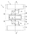
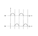
図1は、本発明のアクチュエータの第1実施形態を示す平面図、図2は、図1中のA−A線断面図、図3は、図1に示すアクチュエータの第2の質量部と第2の弾性連結部との連結状態を説明するための部分拡大斜視図、図4は、図1に示すアクチュエータの電極の配置を示す平面図、図5は、印加する交流電圧の一例を示す図、図6は、印加した交流電圧の周波数と、第1の質量部および第2の質量部の共振曲線を示すグラフである。なお、以下では、説明の便宜上、図1および図4中の紙面手前側を「上」、紙面奥側を「下」、右側を「右」、左側を「左」と言い、図2中の上側を「上」、下側を「下」、右側を「右」、左側を「左」と言う。
DESCRIPTION OF EXEMPLARY EMBODIMENTS Hereinafter, preferred embodiments of an actuator of the invention will be described with reference to the accompanying drawings.
<First Embodiment>
First, a first embodiment of the actuator of the present invention will be described.
1 is a plan view showing a first embodiment of the actuator of the present invention, FIG. 2 is a cross-sectional view taken along line AA in FIG. 1, and FIG. 3 is a diagram showing a second mass portion and a second portion of the actuator shown in FIG. FIG. 4 is a plan view showing the arrangement of the electrodes of the actuator shown in FIG. 1, and FIG. 5 is a diagram showing an example of an AC voltage to be applied. FIG. 6 is a graph showing the frequency of the applied AC voltage and the resonance curves of the first mass part and the second mass part. In the following, for convenience of explanation, the front side of the page in FIGS. 1 and 4 is referred to as “up”, the back side of the page is referred to as “down”, the right side is referred to as “right”, and the left side is referred to as “left”. The upper side is called “upper”, the lower side is called “lower”, the right side is called “right”, and the left side is called “left”.
アクチュエータ1は、図1に示すような2自由度振動系を有する基体2を有しており、図2に示すように、この基体2の下部には、対向基板3が接合されている。
基体2は、1対の第1の質量部(駆動部)21、22と、1対の支持部23、24と、第2の質量部(可動部)25と、1対の第1の弾性連結部26、27と、1対の第2の弾性連結部28、29とを備えている。このような基体2にあっては、左右対称な形状となるように、第2の質量部25を中心とし、その左方に、第2の弾性連結部28、第1の質量部21、支持部23が順次配設され、右方に、第2の弾性連結部29、第1の質量部22、支持部24が順次配設されている。
The
The
1対の第1の質量部21、22は、それぞれ、板状をなし、互いにほぼ同一寸法でほぼ同一形状をなしている。
また、1対の質量部21、22の間には、第2の質量部25が設けられており、1対の質量部21、22は、第2の質量部25を中心として、ほぼ左右対称となるように設けられている。
The pair of first
In addition, a
第2の質量部25は、板状をなし、その板面に光反射部251が設けられている。これにより、アクチュエータ1を光スキャナ、光アッテネータ、光スイッチなどの光デバイスに適用することができる。
このような第1の質量部21、22および第2の質量部25にあっては、第1の質量部21、22が第1の弾性連結部26、27を介して支持部23、24に接続され、第2の質量部25が第2の弾性連結部28、29を介して第1の質量部21、22に接続されている。
The
In such
第1の弾性連結部26は、第1の質量部21を支持部23に対して回動可能とするように、第1の質量部21と支持部23とを連結している。これと同様に、第1の弾性連結部27は、第1の質量部22を支持部24に対して回動可能とするように、第1の質量部22と支持部24とを連結している。
第2の弾性連結部28は、第2の質量部25を第1の質量部21に対して回動可能とするように、第2の質量部25と第1の質量部21とを連結している。これと同様に、第2の弾性連結部29は、第2の質量部25を第1の質量部22に対して回動可能とするように、第2の質量部25と第1の質量部22とを連結している。
The first elastic connecting
The second elastic connecting
本発明にかかるアクチュエータ1では、第2の弾性連結部28は、その途中から分岐した2つの分岐部281、282を有している。これと同様に、第2の弾性連結部29は、その途中から分岐した2つの分岐部291、292を有している。
各分岐部281、282、291、292は、第2の質量部25の回動中心軸を介して対向する位置で第2の質量部25に接続されている。より具体的には、各分岐部281、282、291、292は、第2の質量部25の回動中心軸と該回動中心軸からの遠位端との中間点より前記遠位端側で、第2の質量部25に接続されている。
In the
Each
各分岐部281、282、291、292は、図3に示すように、その途中に弾性連結部28の他の部分よりも肉薄な肉薄部を有し、この肉薄部が、第2の弾性連結部28、29から第2の質量部25に伝達されるねじりトルクを緩衝させる緩衝部を構成する。
すなわち、各分岐部281、282、291、292は、その途中に、第2の弾性連結部28、29から第2の質量部25に伝達されるねじりトルクを緩衝させる緩衝部を有する。この緩衝部は、第2の弾性連結部28、29の分岐部281、282、291、292以外の部分のバネ定数よりも低いバネ定数の低バネ定数部で構成されている。
As shown in FIG. 3, each of the
That is, each of the
本実施形態では、このように、緩衝部(肉薄部)の厚さは、第2の弾性連結部28、29の分岐部281、282、291、292以外の部分の厚さよりも小さくなっているが、緩衝部(肉薄部)の幅は第2の弾性連結部28、29の分岐部281、282、291、292以外の部分の幅とほぼ同じになっている。これにより、緩衝部(肉薄部)の横断面積が、第2の弾性連結部28、29の分岐部281、282、291、292以外の部分の横断面積よりも小さくなっている。
なお、分岐部281、282、291、292の途中が前述したような緩衝部を構成することができれば、緩衝部(肉薄部)の幅と、第2の弾性連結部28、29の分岐部281、282、291、292以外の部分の幅とは、異なっていてもよい。
In the present embodiment, as described above, the thickness of the buffer portion (thin portion) is smaller than the thickness of portions other than the
If the middle of the
各第1の弾性連結部26、27および各第2の弾性連結部28、29は、同軸的に設けられており、これらを回動中心軸(回転軸)として、第1の質量部21、22が支持部23、24に対して、また、第2の質量部25が第1の質量部21、22に対して回動可能となっている。
このように、基体2は、第1の質量部21、22と第1の弾性連結部26、27とで構成された第1の振動系と、第2の質量部25と第2の弾性連結部28、29とで構成された第2の振動系とを有する。すなわち、基体2は、第1の振動系および第2の振動系からなる2自由度振動系を有する。
The first elastic connecting
As described above, the
このような2自由度振動系は、基体2の全体の厚さよりも薄く形成されているとともに、図2にて上下方向で基体2の上部に位置している。換言すれば、基体2には、基体2の全体の厚さよりも薄い部分が形成されており、この薄い部分に異形孔が形成されることにより、第1の質量部21、22と第2の質量部25と第1の弾性連結部26、27と第2の弾性連結部28、29とが形成されている。
Such a two-degree-of-freedom vibration system is formed thinner than the entire thickness of the
本実施形態では、前記薄肉部の上面が支持部23、24の上面と同一面上に位置することにより、前記薄い部分の下方には、各質量部21、22、25の回動のための空間(凹部)30が形成されている。
このような基体2は、例えば、シリコンを主材料として構成されていて、第1の質量部21、22と、第2の質量部25と、支持部23、24と、第1の弾性連結部26、27と、第2の弾性連結部28、29とが一体的に形成されている。
In the present embodiment, since the upper surface of the thin portion is located on the same plane as the upper surfaces of the
Such a
なお、基体2は、SOI基板等の積層構造を有する基板から、第1の質量部21、22と、第2の質量部25と、支持部23、24と、第1の弾性連結部26、27と、第2の弾性連結部28、29を形成したものであってもよい。その際、第1の質量部21、22と、第2の質量部25と、支持部23、24の一部と、第1の弾性連結部26、27と、第2の弾性連結部28、29とが一体的となるように、これらを積層構造の基板の1つの層で構成するのが好ましい。
The
前述したような基体2に接合した対向基板3は、例えば、ガラスやシリコンを主材料として構成されている。
対向基板3の上面には、図2および図4に示すように、第2の質量部25に対応する部分に開口部31が形成されている。
この開口部31は、第2の質量部25が回動(振動)する際に、対向基板3に接触するのを防止する逃げ部を構成する。開口部(逃げ部)31を設けることにより、アクチュエータ1全体の大型化を防止しつつ、第2の質量部25の振れ角(振幅)をより大きく設定することができる。
The
As shown in FIGS. 2 and 4, an
The
なお、前述したような逃げ部は、前記効果を十分に発揮し得る構成であれば、必ずしも対向基板3の下面(第2の質量部25と反対側の面)で開放(開口)していなくてもよい。すなわち、逃げ部は、対向基板3の上面に形成された凹部で構成することもできる。また、空間30の深さが第2の質量部25の振れ角(振幅)に対し大きい場合などには、逃げ部を設けなくともよい。
Note that the relief portion as described above is not necessarily opened (opened) on the lower surface of the counter substrate 3 (the surface opposite to the second mass portion 25) as long as the above-described effect can be sufficiently exerted. May be. That is, the escape portion can also be configured by a recess formed on the upper surface of the
また、対向基板3の上面には、図4に示すように、第1の質量部21に対応する部分に、一対の電極32が第1の質量部21の回動中心軸を中心にほぼ対称となるように設けられ、また、第1の質量部22に対応する部分に、一対の電極32が第1の質量部22の回動中心軸を中心にほぼ対称となるように設けられている。すなわち、本実施形態では、一対の電極32が2組(合計4個)、設けられている。
Further, on the upper surface of the
第1の質量部21、22と各電極32とは、図示しない電源に接続されており、第1の質量部21、22と各電極32との間に交流電圧(駆動電圧)を印加できるよう構成されている。
なお、第1の質量部21、22は、各電極32と対向する面に、それぞれ、絶縁膜(図示せず)が設けられている。これにより、第1の質量部21、22と各電極32との間での短絡が発生するのが好適に防止される。
以上のような構成のアクチュエータ1は、次のようにして駆動する。
The
In addition, the
The
すなわち、第1の質量部21、22と各電極32との間に、例えば、正弦波(交流電圧)等を印加する。具体的には、例えば、第1の質量部21、22をアースしておき、図4中上側の2つの電極32に、図5(a)に示すような波形の電圧を印加し、図4中下側の2つの電極32に、図5(b)に示すような波形の電圧を印加する。すると、第1の質量部21、22と各電極32との間に静電気力(クーロン力)が生じる。
That is, for example, a sine wave (AC voltage) or the like is applied between the
この静電気力により、第1の質量部21、22が、各電極32の方へ引きつけられる力が正弦波の位相により変化し、第1の弾性連結部26、27を軸に、対向基板3の板面(図1における紙面)に対して傾斜するように振動(回動)する。
そして、この第1の質量部21、22の振動(駆動)に伴って、第2の弾性連結部28、29を介して連結されている第2の質量部25も、第2の弾性連結部28、29を軸に、対向基板3の板面(図1における紙面)に対して傾斜するように振動(回動)する。
Due to this electrostatic force, the force that the first
The
このとき、第2の弾性連結部28、29から第2の質量部25へ捩りトルクが第2の質量部25の回動中心軸から離れた位置で伝達されるので、駆動時の第2の弾性連結部28、29の横断面形状の変化に伴う第2の質量部25の撓みを抑えるとともに、第2の質量部25の慣性力による撓みを抑えることができる。その際、第2の弾性連結部28、29から第2の質量部25に伝達されるねじりモーメントを分岐部281、282、291、292の緩衝部で低減して、駆動時の分岐部281、282、291、292の撓みに伴う第2の質量部25の撓みも抑えることができる。その結果、第2の質量部25の撓みを大幅に低減して、第2の質量部25の駆動時における平滑性を極めて高いものとすることができる。
At this time, since the torsional torque is transmitted from the second elastic connecting
したがって、アクチュエータ1にあっては、第2の質量部25の振れ角を大きくしたり、第2の質量部25の厚さを小さくしたりしても、第2の質量部25の撓みを抑えて、高精度に駆動を行うことができる。
特に、本実施形態では、緩衝部(肉薄部)の厚さが、第2の弾性連結部28、29の分岐部281、282、291、292以外の部分の厚さよりも小さくなっているので、比較的簡単な構成で、駆動時における第2の質量部25の撓みを大幅に低減することができる。
Therefore, in the
In particular, in the present embodiment, the thickness of the buffer portion (thin portion) is smaller than the thickness of portions other than the
また、緩衝部(肉薄部)の横断面積が、第2の弾性連結部28、29の分岐部281、282、291、292以外の部分の横断面積よりも小さくなっているので、この点でも、比較的簡単な構成で、駆動時における第2の質量部25の撓みを大幅に低減することができる。
その際、緩衝部の横断面積をAとし、第2の弾性連結部28、29の分岐部281、282、291、292以外の部分の横断面積をBとしたとき、1/4<A/B<1の関係を満たすのが好ましく、1/4<A/B<1/2の関係を満たすのがより好ましい。これにより、比較的簡単な構成で、かつ、より確実に、駆動時における第2の質量部25の撓みを低減することができる。
In addition, since the cross-sectional area of the buffer portion (thin portion) is smaller than the cross-sectional area of the second elastic connecting
At that time, when the cross-sectional area of the buffer portion is A and the cross-sectional area of the second elastic connecting
また、前述した緩衝部は、第2の弾性連結部28、29の分岐部281、282、291、292以外の部分のバネ定数よりも低いバネ定数の低バネ定数部で構成されているので、第2の弾性連結部28、29のねじり変形に対する第2の質量部25の追従性(応答性)を良好なものとしつつ、駆動時における第2の質量部25の撓みを大幅に低減することができる。
Moreover, since the buffer part mentioned above is comprised by the low spring constant part of a spring constant lower than the spring constant of parts other than the branch parts 281,282,291,292 of the 2nd
また、各分岐部281、282、291、292は、第2の質量部25の回動中心軸と該回動中心軸からの遠位端との中間点より前記遠位端側で、第2の質量部25に接続されているので、より確実に、駆動時における第2の質量部25の撓みを大幅に低減することができる。
また、第2の弾性連結部28、29は、第2の質量部25を介して、その両側に1対設けられ、1対の第2の弾性連結部28、29がそれぞれ分岐部を有しているので、駆動時における第2の質量部25の撓みを大幅に低減するとともに、第2の質量部25をより高精度に駆動することができる。
In addition, each of the
A pair of second
また、第1の質量部21の回動中心軸からこれにほぼ垂直な方向(長手方向)での長さをL1とし、第1の質量部22の回動中心軸からこれにほぼ垂直な方向(長手方向)での長さをL2とし、第2の質量部25の回動中心軸からこれにほぼ垂直な方向での長さをL3としたとき、本実施形態では、第1の質量部21、22が、それぞれ独立して設けられているため、第2の質量部25の大きさ(長さL3)にかかわらず、第1の質量部21、22と第2の質量部25とが干渉せず、L1およびL2を小さくすることができる。これにより、第1の質量部21、22の回転角度(振れ角)を大きくすることができ、その結果、第2の質量部25の回転角度を大きくすることができる。
Further, the length in the direction substantially perpendicular thereto from the pivoting central axis of the first mass portion 21 (longitudinal direction) and L 1, which in a substantially perpendicular from the pivoting central axis of the
また、L1およびL2を小さくすることにより、第1の質量部21、22と各電極32との間の距離を小さくすることができ、これにより、静電気力が大きくなり、第1の質量部21、22と各電極32に印加する交流電圧を小さくすることができる。
ここで、第1の質量部21、22および第2の質量部25の寸法は、それぞれ、L1<L3かつL2<L3なる関係を満足するよう設定されるのが好ましい。
In addition, by reducing L 1 and L 2 , the distance between the
Here, it is preferable that the dimensions of the
前記関係を満たすことにより、L1およびL2をより小さくすることができ、第1の質量部21、22の回転角度をより大きくすることができ、第2の質量部25の回転角度をさらに大きくすることができる。
この場合、第2の質量部25の最大回転角度が、20°以上となるように構成されるのが好ましい。
By satisfying the above relationship, L 1 and L 2 can be made smaller, the rotation angle of the
In this case, it is preferable that the maximum rotation angle of the
また、このように、L1およびL2を小さくすることにより、第1の質量部21、22と各電極32との間の距離をより小さくすることができ、第1の質量部21、22と各電極32に印加する交流電圧をさらに小さくすることができる。
これらによって、第1の質量部21、22の低電圧駆動と、第2の質量部25の大回転角度での振動(回動)とを実現することができる。
このため、このようなアクチュエータ1を、例えばレーザープリンタや、走査型共焦点レーザー顕微鏡等の装置に用いられる光スキャナに適用した場合には、より容易に装置を小型化することができる。
In addition, by reducing L 1 and L 2 in this way, the distance between the
By these, the low voltage drive of the
For this reason, when such an
なお、前述したように、本実施形態では、L1とL2とはほぼ等しく設定されているが、L1とL2とが異なっていてもよいことは言うまでもない。
ところで、このような質量部21、22、25よりなる振動系(2自由度振動系)では、第1の質量部21、22および第2の質量部25の振幅(振れ角)と、印加する交流電圧の周波数との間に、図6に示すような周波数特性が存在している。
As described above, in the present embodiment, L 1 and L 2 are set to be substantially equal, but it goes without saying that L 1 and L 2 may be different.
By the way, in such a vibration system (two-degree-of-freedom vibration system) composed of the
すなわち、かかる振動系は、第1の質量部21、22の振幅と、第2の質量部25の振幅とが大きくなる2つの共振周波数fm1[kHz]、fm3[kHz](ただし、fm1<fm3)と、第1の質量部21、22の振幅がほぼ0となる、1つの反共振周波数fm2[kHz]とを有している。
この振動系では、第1の質量部21、22と電極32との間に印加する交流電圧の周波数Fが、2つの共振周波数のうち低いもの、すなわち、fm1とほぼ等しくなるように設定するのが好ましい。これにより、第1の質量部21、22の振幅を抑制しつつ、第2の質量部25の振れ角(回転角度)を大きくすることができる。
なお、本明細書中では、F[kHz]とfm1[kHz]とがほぼ等しいとは、(fm1−1)≦F≦(fm1+1)の条件を満足することを意味する。
That is, the vibration system has two resonance frequencies fm 1 [kHz] and fm 3 [kHz] (however, fm) in which the amplitude of the
In this vibration system, the frequency F of the AC voltage applied between the
In this specification, F [kHz] and fm 1 [kHz] being substantially equal means that the condition of (fm 1 −1) ≦ F ≦ (fm 1 +1) is satisfied.
第1の質量部21、22の平均厚さは、それぞれ、1〜1500μmであるのが好ましく、10〜300μmであるのがより好ましい。
第2の質量部25の平均厚さは、1〜1500μmであるのが好ましく、10〜300μmであるのがより好ましい。
第1の弾性連結部26、27のばね定数k1は、1×10⁻⁴〜1×10⁴Nm/radであるのが好ましく、1×10−2〜1×103Nm/radであるのがより好ましく、1×10−1〜1×102Nm/radであるのがさらに好ましい。これにより、第2の質量部25の回転角度(振れ角)をより大きくすることができる。
The average thicknesses of the
The average thickness of the second
The spring constant k 1 of the first
一方、第2の弾性連結部28、29のばね定数k2は、1×10⁻⁴〜1×10⁴Nm/radであるのが好ましく、1×10−2〜1×103Nm/radであるのがより好ましく、1×10−1〜1×102Nm/radであるのがさらに好ましい。これにより、第1の質量部21、22の振れ角を抑制しつつ、第2の質量部25の振れ角をより大きくすることができる。
On the other hand, the spring constant k 2 of the second elastic connecting
また、第1の弾性連結部26、27のばね定数k1と第2の弾性連結部28、29のばね定数をk2とは、k1>k2なる関係を満足するのが好ましい。これにより、第1の質量部21、22の振れ角を抑制しつつ、第2の質量部25の回転角度(振れ角)をより大きくすることができる。
さらに、第1の質量部21、22の慣性モーメントをJ1とし、第2の質量部25の慣性モーメントをJ2としたとき、J1とJ2とは、J1≦J2なる関係を満足することが好ましく、J1<J2なる関係を満足することがより好ましい。これにより、第1の質量部21、22の振れ角を抑制しつつ、第2の質量部25の回転角度(振れ角)をより大きくすることができる。
Further, the spring constant k 1 of the first elastic connecting
Furthermore, the moment of inertia of the first
ところで、第1の質量部21、22と第1の弾性連結部26、27とからなる第1の振動系の固有振動数ω1は、第1の質量部21、22の慣性モーメントJ1と、第1の弾性連結部26、27のばね定数k1とにより、ω1=(k1/J1)1/2によって与えられる。一方、第2の質量部25と第2の弾性連結部28、29とからなる第2の振動系の固有振動数ω2は、第2の質量部25の慣性モーメントJ2と、第2の弾性連結部28、29のばね定数k2とにより、ω2=(k2/J2)1/2によって与えられる。
このようにして求められる第1の振動系の固有振動数ω1と第2の振動系の固有振動数ω2とは、ω1>ω2なる関係を満足するのが好ましい。これにより、第1の質量部21、22の振れ角を抑制しつつ、第2の質量部25の回転角度(振れ角)をより大きくすることができる。
Incidentally, the natural frequency ω 1 of the first vibration system composed of the
It is preferable that the natural frequency ω 1 of the first vibration system and the natural frequency ω 2 of the second vibration system obtained in this way satisfy the relationship ω 1 > ω 2 . Thereby, the rotation angle (swing angle) of the
このようなアクチュエータ1は、例えば、次のようにして製造することができる。
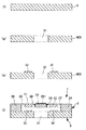
図7、図8は、それぞれ、第1実施形態のアクチュエータの製造方法を説明するための図(縦断面図)である。なお、以下では、説明の便宜上、図7、図8中の上側を「上」、下側を「下」と言う。
Such an
7 and 8 are views (longitudinal sectional views) for explaining the manufacturing method of the actuator of the first embodiment. In the following, for convenience of explanation, the upper side in FIGS. 7 and 8 is referred to as “upper” and the lower side is referred to as “lower”.
[A1] まず、図7(a)に示すように、例えばシリコン基板5を用意する。
次に、シリコン基板5の一方の面に、図7(b)に示すように、支持部23、24と各質量部21、22、25と各弾性連結部26、27、28、29との形状(平面視形状)に対応するように、例えば、アルミニウム等により金属マスク6を形成する。
そして、図7(c)に示すように、シリコン基板5の他方の面に、フォトレジストを塗布し、露光、現像を行う。これにより、図7(c)に示すように、支持部23、24の形状に対応するように、レジストマスク7を形成する。なお、レジストマスク7の形成は、金属マスク6の形成よりも先に行ってもよい。
[A1] First, as shown in FIG. 7A, for example, a
Next, on one surface of the
Then, as shown in FIG. 7C, a photoresist is applied to the other surface of the
次に、このレジストマスク7を介して、シリコン基板5の前記他方の面をエッチングした後、レジストマスク7を除去する。これにより、図7(d)に示すように、支持部23、24に対応する部分以外の領域に凹部51が形成される。
エッチング方法としては、例えば、プラズマエッチング、リアクティブイオンエッチング、ビームエッチング、光アシストエッチング等の物理的エッチング法、ウェットエッチング等の化学的エッチング法等のうちの1種または2種以上を組み合わせて用いることができる。なお、以下の各工程におけるエッチングにおいても、同様の方法を用いることができる。
Next, after etching the other surface of the
As an etching method, for example, one or more of physical etching methods such as plasma etching, reactive ion etching, beam etching, and light-assisted etching, and chemical etching methods such as wet etching are used in combination. be able to. Note that the same method can be used for etching in the following steps.
次に、金属マスク6を介して、シリコン基板5の前記一方の面側を、前記凹部51に対応する部分が貫通するまでエッチングする。
そして、シリコン基板5の分岐部281、282、291、292の肉薄部に対応する部分をシリコン基板5の前記他方の面側からエッチングやレーザ加工等により肉薄化する。
Next, the one surface side of the
Then, the portions corresponding to the thin portions of the
そして、金属マスク6を除去した場合、この後、第2の質量部25上に金属膜を成膜し、光反射部251を形成する。
なお、ここで、シリコン基板5に対しエッチングを行った後、金属マスク6は除去してもよく、除去せずに残存させてもよい。金属マスク6を除去しない場合、第2の質量部25上に残存した金属マスク6は光反射部251として用いることができる。
Then, when the metal mask 6 is removed, a metal film is formed on the
Here, after etching the
金属膜の成膜方法としては、真空蒸着、スパッタリング(低温スパッタリング)、イオンプレーティング等の乾式メッキ法、電解メッキ、無電解メッキ等の湿式メッキ法、溶射法、金属箔の接合等が挙げられる。なお、以下の各工程における金属膜の成膜においても、同様の方法を用いることができる。
以上の工程により、図7(e)に示すように、支持部23、24と各質量部21、22、25と各弾性連結部26、27、28、29とが一体的に形成された構造体、すなわち基体2が得られる。
Examples of the method for forming a metal film include vacuum plating, sputtering (low temperature sputtering), dry plating methods such as ion plating, wet plating methods such as electrolytic plating and electroless plating, thermal spraying methods, and joining metal foils. . Note that the same method can also be used for forming a metal film in the following steps.
Through the above steps, as shown in FIG. 7 (e), the
[A2] 次に、図8(f)に示すように、対向基板3を形成するための基板として、例えばシリコン基板9を用意する。
そして、シリコン基板9の一方の面に、開口部31を形成する領域を除いた部分に対応するように、例えば、アルミニウム等により金属マスクを形成する。
次に、この金属マスクを介して、シリコン基板9の一方の面側をエッチングした後、図8(g)に示すように、金属マスクを除去する。
[A2] Next, as shown in FIG. 8F, for example, a
Then, a metal mask is formed on one surface of the
Next, after etching one surface side of the
次に、シリコン基板9上に、図8(h)に示すように、電極32を形成し、対向基板3が得られる。
電極32は、シリコン基板9に金属膜を成膜し、電極32の形状に対応するマスクを介して金属膜をエッチングを行った後、マスクを除去することにより形成することができる。
Next, as shown in FIG. 8H, the
The
次に、図8(i)に示すように、前記工程[A1]で得られた構造体の基体2と、前記工程[A2]で得られた対向基板3とを直接接合により接合して、アクチュエータ1を得る。なお、基体2と対向基板3との間に可動イオンを含む硼珪酸ガラスのようなガラスを介在させ、これらを陽極接合により接合してもよい。また、シリコン基板9に代えてガラス基板を用いて、基体2と対向基板3とを陽極接合により接合することもできる。
以上のようにして、第1実施形態のアクチュエータ1が製造される。
Next, as shown in FIG. 8 (i), the
As described above, the
<第2実施形態>
次に、本発明のアクチュエータの第2実施形態について説明する。
図9は、本発明のアクチュエータの第2実施形態を示す平面図、図10は、図9に示すアクチュエータの第2の質量部と第2の弾性連結部との連結状態を説明するための部分拡大斜視図である。なお、以下では、説明の便宜上、図9中の紙面に対し手前側を「上」、紙面に対し奥側を「下」、右側を「右」、左側を「左」、図10中の上側を「上」、下側を「下」、右側を「右」、左側を「左」と言う。
<Second Embodiment>
Next, a second embodiment of the actuator of the present invention will be described.
FIG. 9 is a plan view showing a second embodiment of the actuator of the present invention, and FIG. 10 is a part for explaining the connection state between the second mass part and the second elastic connection part of the actuator shown in FIG. It is an expansion perspective view. In the following, for convenience of explanation, the front side of the paper surface in FIG. 9 is “up”, the back side is “down”, the right side is “right”, the left side is “left”, and the upper side in FIG. Is called "upper", the lower side is called "lower", the right side is called "right", and the left side is called "left".
以下、第2実施形態のアクチュエータについて、前述した第1実施形態のアクチュエータとの相違点を中心に説明し、同様の事項については、その説明を省略する。
第2実施形態のアクチュエータ1Aは、図9および図10に示すように、第2の弾性連結部28、29に代えて第2の弾性連結部28A、29Aを有していて、第2の弾性連結部の構成が異なる以外は、第1実施形態のアクチュエータ1とほぼ同様である。
Hereinafter, the actuator of the second embodiment will be described focusing on the differences from the actuator of the first embodiment described above, and the description of the same matters will be omitted.
As shown in FIGS. 9 and 10, the actuator 1A of the second embodiment includes second
第2実施形態のアクチュエータ1Aは、図9に示すように、2自由度振動系を有する基体2Aを有しており、その基体2Aにおいて、第2の弾性連結部28Aは、その途中から分岐した2つの分岐部281A、282Aを有している。これと同様に、第2の弾性連結部29Aは、その途中から分岐した2つの分岐部291A、292Aを有している。
各分岐部281A、282A、291A、292Aは、図9および図10に示すように、その途中に、矩形に複数回折れ曲がった部分を有し、この部分が、第2の弾性連結部28A、29Aから第2の質量部25に伝達されるねじりトルクを緩衝させる緩衝部を構成する。このような緩衝部によっても、駆動時における第2の質量部25の撓みを大幅に低減することができる。
As shown in FIG. 9, the actuator 1A of the second embodiment has a
As shown in FIGS. 9 and 10, each of the
特に、このような緩衝部は、比較的簡単な構成で、駆動時における第2の質量部25の撓みを大幅に低減することができる。また、このような場合、アクチュエータの製造時において、前述した第1実施形態のような肉薄化を必要とせずに緩衝部を形成することができるので、アクチュエータの製造工程をより簡略化することができる。なお、分岐部281A、282A、291A、292Aの緩衝部を、前述した第1実施形態のように肉薄化してもよい。この場合、第2の弾性連結部28A、29Aから第2の質量部25に伝達されるねじりトルクをより効果的に緩衝させることができる。
In particular, such a buffer portion has a relatively simple configuration and can significantly reduce the bending of the
なお、本実施形態では、分岐部を矩形に複数回折り曲げて緩衝部を構成した場合について説明したが、緩衝部を構成することができれば、これに限定されず、緩衝部を構成する分岐部の折り曲げ形状は任意である。また、本実施形態では、第2の質量部25の板面にほぼ平行な面上で分岐部が複数回折り曲げられているが、これに限定されず、例えば、第2の質量部25の板面に直角な面上で分岐部が複数回折り曲げられていてもよい。
In the present embodiment, the case where the buffer portion is configured by bending a plurality of branch portions into a rectangular shape has been described. However, if the buffer portion can be configured, the present invention is not limited to this, and the branch portion constituting the buffer portion is not limited thereto. The bent shape is arbitrary. Further, in the present embodiment, a plurality of branch portions are bent and bent on a surface substantially parallel to the plate surface of the
<参考例>
次に、参考例のアクチュエータについて説明する。
図11は、参考例のアクチュエータを示す平面図、図12は、図11におけるA−A線断面図である。なお、以下では、説明の便宜上、図11中の紙面に対し手前側を「上」、紙面に対し奥側を「下」、右側を「右」、左側を「左」、図12中の上側を「上」、下側を「下」、右側を「右」、左側を「左」と言う。
< Reference example >
Next, a description will be given of the actuator of the reference example.
FIG. 11 is a plan view showing an actuator of a reference example , and FIG. 12 is a cross-sectional view taken along line AA in FIG. In the following, for convenience of explanation, the front side with respect to the paper surface in FIG. 11 is “up”, the back side with respect to the paper surface is “down”, the right side is “right”, the left side is “left”, and the upper side in FIG. Is called "upper", the lower side is called "lower", the right side is called "right", and the left side is called "left".
以下、参考例のアクチュエータについて、前述した第1実施形態のアクチュエータとの相違点を中心に説明し、同様の事項については、その説明を省略する。
参考例のアクチュエータ1Bは、1自由度振動系のアクチュエータである以外は、第1実施形態のアクチュエータ1とほぼ同様である。
すなわち、図11及び図12に示すアクチュエータ1Bは、図1にて、前述の第1実施形態のアクチュエータ1の第1の質量部21、22および第1の弾性連結部26、27を省略し、第2の質量部25を第2の弾性連結部28、29を介して支持部23、24に接続したような構成となっている。
Hereinafter, the actuator of the reference example will be described focusing on the differences from the actuator of the first embodiment described above, and the description of the same matters will be omitted.
The
That is, the
より具体的に説明すると、図11及び図12に示すアクチュエータ1Bは、1自由度振動系を有する基体2Bが対向基板3Bに接合されている。
基体2Bは、1対の支持部23、24と、質量部(可動部)25Bと、1対の弾性連結部28B、29Bとを備えている。このような基体2Bにあっては、左右対称な形状となるように、質量部25Bを中心とし、その左方に、弾性連結部28B、支持部23が順次配設され、右方に、弾性連結部29B、支持部24が順次配設されている。
More specifically, in the
The base body 2B includes a pair of
質量部25Bは、前述した第1実施形態の第2の質量部25と同様に、板状をなし、その板面に光反射部251Bが設けられている。これにより、アクチュエータ1Bを光スキャナ、光アッテネータ、光スイッチなどの光デバイスに適用することができる。
このような質量部25Bは、弾性連結部28B、29Bを介して支持部23、24に接続されている。
The
Such a
弾性連結部28Bは、質量部25Bを支持部23に対して回動可能とするように、質量部25Bと支持部23とを連結している。これと同様に、弾性連結部29Bは、質量部25Bを支持部24に対して回動可能とするように、質量部25Bと支持部24とを連結している。
参考例にかかるアクチュエータ1Bでは、弾性連結部28B、29Bは、弾性連結部28Bは、その途中から分岐した2つの分岐部281B、282Bを有している。これと同様に、第2の弾性連結部29Bは、その途中から分岐した2つの分岐部291B、292Bを有している。
The elastic connecting
In the
各分岐部281B、282B、291B、292Bは、質量部25Bの回動中心軸を介して対向する位置で質量部25Bに接続されている。より具体的には、各分岐部281B、282B、291B、292Bは、質量部25Bの回動中心軸と、該回動中心軸からの遠位端との中間点より前記遠位端側で、質量部25Bに接続されている。
各分岐部281B、282B、291B、292Bは、図12に示すように、前述した第1実施形態の各分岐部281、282、291、292と同様、その途中に弾性連結部28B、29Bよりも肉薄な肉薄部を有し、この肉薄部が、弾性連結部28B、29Bから質量部25Bに伝達されるねじりトルクを緩衝させる緩衝部を構成する。
Each
As shown in FIG. 12, each of the
このように、基体2Bは、質量部25Bと弾性連結部28B、29Bとで構成された1自由度振動系を有する。
このような1自由度振動系は、基体2Bの全体の厚さよりも薄く形成されているとともに、図12にて上下方向で基体2Bの上部に位置している。
前述したような基体2に接合した対向基板3は、例えば、ガラスやシリコンを主材料として構成されている。
As described above, the base body 2B has a one-degree-of-freedom vibration system including the
Such a one-degree-of-freedom vibration system is formed thinner than the entire thickness of the base 2B, and is positioned above the base 2B in the vertical direction in FIG.
The
対向基板3Bの上面には、図11および図12に示すように、質量部25に対応する部分に、一対の電極32Bが質量部25Bの回動中心軸を中心にほぼ対称となるように設けられている。
質量部25Bと各電極32Bとは、図示しない電源に接続されており、質量部25Bと各電極32Bとの間に交流電圧(駆動電圧)を印加できるよう構成されている。
なお、質量部25Bは、各電極32Bと対向する面に、絶縁膜(図示せず)が設けられている。これにより、質量部25と各電極32Bとの間での短絡が発生するのが好適に防止される。
On the upper surface of the
The
The
以上のような構成のアクチュエータ1Bは、次のようにして駆動する。
すなわち、質量部25Bと各電極32Bとの間に、例えば、正弦波(交流電圧)等を印加する。具体的には、例えば、質量部25Bをアースしておき、図11中上側の電極32Bに、図5(a)に示すような波形の電圧を印加し、図11中下側の電極32Bに、図5(b)に示すような波形の電圧を印加する。すると、質量部25Bと各電極32Bとの間に静電気力(クーロン力)が生じる。
The
That is, for example, a sine wave (AC voltage) or the like is applied between the
この静電気力により、質量部25Bが、各電極32Bの方へ引きつけられる力が正弦波の位相により変化し、弾性連結部28B、29Bを軸に、対向基板3Bの板面(図11における紙面)に対して傾斜するように振動(回動)する。
このとき、弾性連結部28B、29Bから質量部25Bへ捩りトルクが質量部25Bの回動中心軸から離れた位置で伝達されるので、駆動時の弾性連結部28B、29Bの横断面形状変化にともなう質量部25Bの撓みを抑えるとともに、質量部25Bの慣性力による撓みを抑えることができる。その際、弾性連結部28B、29Bから質量部25Bに伝達されるねじりモーメントを分岐部281B、282B、291B、292Bの緩衝部で低減して、分岐部281B、282B、291B、292Bの撓みに伴う質量部25Bの駆動時における撓みを抑えることができる。
Due to this electrostatic force, the force that the
At this time, since the torsional torque is transmitted from the elastic connecting
特に、本参考例では、緩衝部(肉薄部)の厚さが、弾性連結部28B、29Bの分岐部281B、282B、291B、292B以外の部分の厚さよりも小さくなっているので、比較的簡単な構成で、駆動時における質量部25Bの撓みを大幅に低減することができる。
また、緩衝部(肉薄部)の横断面積が、弾性連結部28B、29Bの分岐部281B、282B、291B、292B以外の部分の横断面積よりも小さくなっているので、この点でも、比較的簡単な構成で、駆動時における質量部25Bの撓みを大幅に低減することができる。
In particular, in this reference example , since the thickness of the buffer portion (thin portion) is smaller than the thickness of the elastic connecting
Further, since the cross-sectional area of the buffer portion (thin portion) is smaller than the cross-sectional area of the elastic connecting
また、緩衝部の横断面積をAとし、弾性連結部28B、29Bの分岐部281B、282B、291B、292B以外の部分の横断面積をBとしたとき、1/4<A/B<1の関係を満たすのが好ましく、1/4<A/B<1/2の関係を満たすのがより好ましい。これにより、比較的簡単な構成で、かつ、より確実に、駆動時における質量部25Bの撓みを低減することができる。
Further, when the cross-sectional area of the buffer portion is A and the cross-sectional area of the elastic connecting
また、前述した緩衝部は、弾性連結部28B、29Bの分岐部281B、282B、291B、292B以外の部分のバネ定数よりも低いバネ定数の低バネ定数部で構成されているので、弾性連結部28B、29Bのねじり変形に対する質量部25Bの追従性を良好なものとしつつ、駆動時における質量部25Bの撓みを大幅に低減することができる。
また、各分岐部281B、282B、291B、292Bは、質量部25Bの回動中心軸と、該回動中心軸からの遠位端との中間点より前記遠位端側で、質量部25Bに接続されているので、より確実に、駆動時における質量部25Bの撓みを大幅に低減することができる。
Moreover, since the buffer part mentioned above is comprised by the low spring constant part of a spring constant lower than the spring constant of parts other than
In addition, each of the
また、弾性連結部28B、29Bは、質量部25Bを介して、その両側に1対設けられ、1対の弾性連結部28B、29Bがそれぞれ分岐部を有しているので、駆動時における質量部25Bの撓みを大幅に低減するとともに、質量部25Bをより高精度に駆動することができる。
上述したようなアクチュエータ1〜1Bは、各種の電子機器に適用することができ、得られる電子機器は、信頼性の高いものとなる。
The elastic connecting
The
以上説明したようなアクチュエータ1〜1Bは、例えば、レーザープリンタ、バーコードリーダー、走査型共焦点レーザー顕微鏡等の光スキャナ、イメージング用ディスプレイ等に好適に適用することができる。
以上、本発明のアクチュエータについて、図示の実施形態に基づいて説明したが、本発明はこれに限定されるものではない。例えば、本発明のアクチュエータでは、各部の構成は、同様の機能を発揮する任意の構成のものに置換することができ、また、任意の構成を付加することもできる。
The
The actuator of the present invention has been described based on the illustrated embodiment, but the present invention is not limited to this. For example, in the actuator of the present invention, the configuration of each part can be replaced with an arbitrary configuration that exhibits the same function, and an arbitrary configuration can be added.
また、前述した第1、2実施形態および参考例では、質量部(または第1の質量部、第2の質量部)の回動軸線を通り支持基板の板面に直角な面に対しほぼ対称な形状をなしている構造を説明したが、非対称であってもよい。また、アクチュエータの中心を通り質量部(または第1の質量部、第2の質量部)の回動軸線に直角な面に対しほぼ対称な形状をなしている構造を説明したが、非対称であってもよい。 In the first and second embodiments and the reference examples described above, the plane is substantially symmetrical with respect to a plane that passes through the rotation axis of the mass section (or the first mass section and the second mass section) and is perpendicular to the plate surface of the support substrate. Although a structure having a simple shape has been described, it may be asymmetric. In addition, the structure has been described that is almost symmetrical with respect to a plane perpendicular to the rotation axis of the mass part (or the first mass part or the second mass part) through the center of the actuator. May be.
また、前述した第1、2実施形態では、第1の弾性連結部を1対有するものとして説明したが、これに限定されず、例えば、2対以上であってもよい。
また、前述した第1、2実施形態では、第2の弾性連結部を1対有するものとして説明したが、これに限定されず、例えば、2対以上であってもよい。
また、前述した第3実施形態では、弾性連結部を1対有するものとして説明したが、これに限定されず、例えば、2対以上であってもよい。
In the first and second embodiments described above, the first elastic coupling portion is described as having one pair. However, the present invention is not limited to this, and may be, for example, two or more pairs.
In the first and second embodiments described above, the second elastic coupling portion is described as having one pair. However, the present invention is not limited to this and may be, for example, two or more pairs.
In the above-described third embodiment, the pair of elastic coupling portions has been described. However, the present invention is not limited to this, and for example, two or more pairs may be used.
また、前述した実施形態では、光反射部が質量部または第2の質量部の上面(対向基板とは逆側の面)に設けられている構成について説明したが、例えば、その逆の面に設けられている構成であってもよいし、両方の面に設けられている構成であってもよい。
また、前述した実施形態では静電駆動方式により駆動するものについて説明したが、これに限定されない。例えば、2自由度振動系を有するアクチュエータの駆動方式としては、第1の質量部を回動させ、これに伴い、第2の弾性連結部を捩り変形させながら、第2の質量部を回動させることができるものであれば、前述したものに限定されず、例えば、圧電素子を用いた駆動方式であってもよい。また、1自由度振動系を有するアクチュエータの駆動方式としては、弾性連結部を捩り変形させながら、質量部を回動させることができるものであれば、前述したものに限定されず、例えば、圧電素子を用いた駆動方式であってもよい。
In the above-described embodiment, the configuration in which the light reflecting portion is provided on the upper surface (the surface opposite to the counter substrate) of the mass portion or the second mass portion has been described. The structure provided may be sufficient and the structure provided in both surfaces may be sufficient.
Moreover, although what was driven by the electrostatic drive system was demonstrated in embodiment mentioned above, it is not limited to this. For example, as a driving method for an actuator having a two-degree-of-freedom vibration system, the second mass unit is rotated while the first mass unit is rotated and the second elastic coupling unit is twisted and deformed accordingly. However, the driving method using a piezoelectric element may be used, for example. The driving method of the actuator having a one-degree-of-freedom vibration system is not limited to the above-described one as long as the mass portion can be rotated while twisting and deforming the elastic coupling portion. A driving method using an element may be used.
1、1A、1B……アクチュエータ 2、2A、2B……基体 21、22……第1の質量部 23、24……支持部 25……第2の質量部 25B……質量部 251、251B……光反射部 26、27……第1の弾性連結部 28、29……第2の弾性連結部 28B、29B……弾性連結部 281、281A、281B、282、282A、282B、291、291A、291B、292、292A、292B……分岐部 3、3B……対向基板 30……空間 31……開口部 32、32B……電極 5……シリコン基板 51……凹部 6……金属マスク 7……レジストマスク 9……シリコン基板
DESCRIPTION OF
Claims (8)
前記第1の質量部を支持するための支持部と、
前記支持部に対して前記第1の質量部を回動可能とするように、前記支持部と前記第1の質量部とを連結する第1の弾性連結部と、
略板状をなす第2の質量部と、
前記第1の質量部に対して前記第2の質量部を回動可能とするように、前記第1の質量部と前記第2の質量部とを連結する第2の弾性連結部とを有し、
前記第1の弾性連結部を捩り変形させながら、前記第1の質量部を回動させ、これに伴い、前記第2の弾性連結部を捩り変形させながら、前記第2の質量部を回動させるように構成されたアクチュエータであって、
前記第2の弾性連結部は、その途中から分岐して、前記第2の質量部の回動中心軸を介して対向する位置で前記第2の質量部に接続された2つの分岐部を有し、
前記各分岐部は、前記第2の弾性連結部の前記分岐部以外の部分のバネ定数よりも低いバネ定数の低バネ定数部で構成された緩衝部を有することを特徴とするアクチュエータ。 A first mass part;
A support part for supporting the first mass part;
A first elastic connecting portion that connects the support portion and the first mass portion so that the first mass portion can be rotated with respect to the support portion;
A second mass part having a substantially plate shape;
A second elastic connecting portion for connecting the first mass portion and the second mass portion so that the second mass portion can be rotated with respect to the first mass portion; And
The first mass portion is rotated while torsionally deforming the first elastic connecting portion, and the second mass portion is rotated while twisting and deforming the second elastic connecting portion accordingly. An actuator configured to cause
The second elastic coupling portion has two branch portions branched from the middle thereof and connected to the second mass portion at positions facing each other via a rotation center axis of the second mass portion. And
Each of the branch portions includes a buffer portion configured by a low spring constant portion having a lower spring constant than a spring constant of a portion other than the branch portion of the second elastic coupling portion .
Priority Applications (1)
| Application Number | Priority Date | Filing Date | Title |
|---|---|---|---|
| JP2005154469A JP4507983B2 (en) | 2005-05-26 | 2005-05-26 | Actuator |
Applications Claiming Priority (1)
| Application Number | Priority Date | Filing Date | Title |
|---|---|---|---|
| JP2005154469A JP4507983B2 (en) | 2005-05-26 | 2005-05-26 | Actuator |
Publications (2)
| Publication Number | Publication Date |
|---|---|
| JP2006330399A JP2006330399A (en) | 2006-12-07 |
| JP4507983B2 true JP4507983B2 (en) | 2010-07-21 |
Family
ID=37552142
Family Applications (1)
| Application Number | Title | Priority Date | Filing Date |
|---|---|---|---|
| JP2005154469A Expired - Fee Related JP4507983B2 (en) | 2005-05-26 | 2005-05-26 | Actuator |
Country Status (1)
| Country | Link |
|---|---|
| JP (1) | JP4507983B2 (en) |
Families Citing this family (6)
| Publication number | Priority date | Publication date | Assignee | Title |
|---|---|---|---|---|
| US8390912B2 (en) | 2007-01-10 | 2013-03-05 | Seiko Epson Corporation | Actuator, optical scanner and image forming device |
| JP4277921B2 (en) | 2007-06-05 | 2009-06-10 | セイコーエプソン株式会社 | Actuator, optical scanner and image forming apparatus |
| JP5105527B2 (en) * | 2008-01-21 | 2012-12-26 | スタンレー電気株式会社 | Optical deflector |
| JP5105526B2 (en) * | 2008-01-21 | 2012-12-26 | スタンレー電気株式会社 | Optical deflector |
| JP6056179B2 (en) * | 2012-04-18 | 2017-01-11 | セイコーエプソン株式会社 | Optical scanner and image forming apparatus |
| JP2015087443A (en) | 2013-10-29 | 2015-05-07 | セイコーエプソン株式会社 | Optical scanner, image display device, head-mounted display, and head-up display |
Citations (2)
| Publication number | Priority date | Publication date | Assignee | Title |
|---|---|---|---|---|
| JP2002156598A (en) * | 2000-11-16 | 2002-05-31 | Omron Corp | Galvanomirror |
| JP2005099760A (en) * | 2003-09-05 | 2005-04-14 | Seiko Epson Corp | Actuator |
Family Cites Families (2)
| Publication number | Priority date | Publication date | Assignee | Title |
|---|---|---|---|---|
| JPS6382165A (en) * | 1986-09-26 | 1988-04-12 | Konica Corp | Picture forming device |
| JP4416117B2 (en) * | 2004-04-19 | 2010-02-17 | 株式会社リコー | Deflection mirror, optical scanning device, and image forming apparatus |
-
2005
- 2005-05-26 JP JP2005154469A patent/JP4507983B2/en not_active Expired - Fee Related
Patent Citations (2)
| Publication number | Priority date | Publication date | Assignee | Title |
|---|---|---|---|---|
| JP2002156598A (en) * | 2000-11-16 | 2002-05-31 | Omron Corp | Galvanomirror |
| JP2005099760A (en) * | 2003-09-05 | 2005-04-14 | Seiko Epson Corp | Actuator |
Also Published As
| Publication number | Publication date |
|---|---|
| JP2006330399A (en) | 2006-12-07 |
Similar Documents
| Publication | Publication Date | Title |
|---|---|---|
| JP4193817B2 (en) | Actuator | |
| JP4385938B2 (en) | Actuator | |
| JP4092283B2 (en) | Two-dimensional optical scanner and optical device | |
| JP4492252B2 (en) | Actuator | |
| US7420315B2 (en) | Actuator | |
| JP3759598B2 (en) | Actuator | |
| JP4507983B2 (en) | Actuator | |
| JP5614167B2 (en) | Optical deflector, optical scanning device, image forming apparatus, and image projecting apparatus | |
| JP2008020701A (en) | Two-dimensional optical scanner, optical device using the same, and method of manufacturing two-dimensional optical scanner | |
| JP2006230048A (en) | Adjusting method of resonance frequency of actuator, and actuator | |
| JP2005128147A (en) | Optical deflector and optical apparatus using the same | |
| JP2007307662A (en) | Actuator | |
| JP2006309018A (en) | Actuator | |
| JP4581847B2 (en) | Actuator | |
| JP2005279863A (en) | Manufacturing method of actuator and actuator | |
| JP2007075978A (en) | Structure manufacturing method and actuator | |
| JP2006167860A (en) | Actuator | |
| JP5353761B2 (en) | Manufacturing method of optical deflector | |
| JP4123133B2 (en) | Actuator | |
| JP2007199213A (en) | Actuator | |
| JP2008003330A (en) | Actuator | |
| JP4175272B2 (en) | Actuator | |
| JP2005279864A (en) | Manufacturing method of actuator and actuator | |
| JP4403785B2 (en) | Actuator manufacturing method and actuator | |
| JP2007222970A (en) | Actuator |
Legal Events
| Date | Code | Title | Description |
|---|---|---|---|
| A621 | Written request for application examination |
Free format text: JAPANESE INTERMEDIATE CODE: A621 Effective date: 20070928 |
|
| A131 | Notification of reasons for refusal |
Free format text: JAPANESE INTERMEDIATE CODE: A131 Effective date: 20100126 |
|
| A977 | Report on retrieval |
Free format text: JAPANESE INTERMEDIATE CODE: A971007 Effective date: 20100126 |
|
| A521 | Written amendment |
Free format text: JAPANESE INTERMEDIATE CODE: A523 Effective date: 20100317 |
|
| TRDD | Decision of grant or rejection written | ||
| A01 | Written decision to grant a patent or to grant a registration (utility model) |
Free format text: JAPANESE INTERMEDIATE CODE: A01 Effective date: 20100413 |
|
| A01 | Written decision to grant a patent or to grant a registration (utility model) |
Free format text: JAPANESE INTERMEDIATE CODE: A01 |
|
| A61 | First payment of annual fees (during grant procedure) |
Free format text: JAPANESE INTERMEDIATE CODE: A61 Effective date: 20100426 |
|
| FPAY | Renewal fee payment (event date is renewal date of database) |
Free format text: PAYMENT UNTIL: 20130514 Year of fee payment: 3 |
|
| R150 | Certificate of patent or registration of utility model |
Ref document number: 4507983 Country of ref document: JP Free format text: JAPANESE INTERMEDIATE CODE: R150 Free format text: JAPANESE INTERMEDIATE CODE: R150 |
|
| FPAY | Renewal fee payment (event date is renewal date of database) |
Free format text: PAYMENT UNTIL: 20140514 Year of fee payment: 4 |
|
| S531 | Written request for registration of change of domicile |
Free format text: JAPANESE INTERMEDIATE CODE: R313531 |
|
| R350 | Written notification of registration of transfer |
Free format text: JAPANESE INTERMEDIATE CODE: R350 |
|
| LAPS | Cancellation because of no payment of annual fees |