JP4505643B2 - Wound retractor device - Google Patents
Wound retractor device Download PDFInfo
- Publication number
- JP4505643B2 JP4505643B2 JP2005500081A JP2005500081A JP4505643B2 JP 4505643 B2 JP4505643 B2 JP 4505643B2 JP 2005500081 A JP2005500081 A JP 2005500081A JP 2005500081 A JP2005500081 A JP 2005500081A JP 4505643 B2 JP4505643 B2 JP 4505643B2
- Authority
- JP
- Japan
- Prior art keywords
- sleeve
- proximal
- ring
- retractor
- instrument
- Prior art date
- Legal status (The legal status is an assumption and is not a legal conclusion. Google has not performed a legal analysis and makes no representation as to the accuracy of the status listed.)
- Expired - Fee Related
Links
Images


Classifications
-
- A—HUMAN NECESSITIES
- A61—MEDICAL OR VETERINARY SCIENCE; HYGIENE
- A61B—DIAGNOSIS; SURGERY; IDENTIFICATION
- A61B17/00—Surgical instruments, devices or methods, e.g. tourniquets
- A61B17/02—Surgical instruments, devices or methods, e.g. tourniquets for holding wounds open; Tractors
- A61B17/0293—Surgical instruments, devices or methods, e.g. tourniquets for holding wounds open; Tractors with ring member to support retractor elements
-
- A—HUMAN NECESSITIES
- A61—MEDICAL OR VETERINARY SCIENCE; HYGIENE
- A61B—DIAGNOSIS; SURGERY; IDENTIFICATION
- A61B17/00—Surgical instruments, devices or methods, e.g. tourniquets
- A61B17/34—Trocars; Puncturing needles
- A61B17/3417—Details of tips or shafts, e.g. grooves, expandable, bendable; Multiple coaxial sliding cannulas, e.g. for dilating
- A61B17/3421—Cannulas
- A61B17/3423—Access ports, e.g. toroid shape introducers for instruments or hands
-
- A—HUMAN NECESSITIES
- A61—MEDICAL OR VETERINARY SCIENCE; HYGIENE
- A61B—DIAGNOSIS; SURGERY; IDENTIFICATION
- A61B17/00—Surgical instruments, devices or methods, e.g. tourniquets
- A61B17/34—Trocars; Puncturing needles
- A61B17/3417—Details of tips or shafts, e.g. grooves, expandable, bendable; Multiple coaxial sliding cannulas, e.g. for dilating
- A61B17/3421—Cannulas
- A61B17/3431—Cannulas being collapsible, e.g. made of thin flexible material
-
- A—HUMAN NECESSITIES
- A61—MEDICAL OR VETERINARY SCIENCE; HYGIENE
- A61B—DIAGNOSIS; SURGERY; IDENTIFICATION
- A61B17/00—Surgical instruments, devices or methods, e.g. tourniquets
- A61B2017/00535—Surgical instruments, devices or methods, e.g. tourniquets pneumatically or hydraulically operated
- A61B2017/00557—Surgical instruments, devices or methods, e.g. tourniquets pneumatically or hydraulically operated inflatable
-
- A—HUMAN NECESSITIES
- A61—MEDICAL OR VETERINARY SCIENCE; HYGIENE
- A61B—DIAGNOSIS; SURGERY; IDENTIFICATION
- A61B17/00—Surgical instruments, devices or methods, e.g. tourniquets
- A61B17/34—Trocars; Puncturing needles
- A61B2017/348—Means for supporting the trocar against the body or retaining the trocar inside the body
- A61B2017/3482—Means for supporting the trocar against the body or retaining the trocar inside the body inside
- A61B2017/3484—Anchoring means, e.g. spreading-out umbrella-like structure
Landscapes
- Health & Medical Sciences (AREA)
- Surgery (AREA)
- Life Sciences & Earth Sciences (AREA)
- Medical Informatics (AREA)
- Nuclear Medicine, Radiotherapy & Molecular Imaging (AREA)
- Engineering & Computer Science (AREA)
- Biomedical Technology (AREA)
- Heart & Thoracic Surgery (AREA)
- Molecular Biology (AREA)
- Animal Behavior & Ethology (AREA)
- General Health & Medical Sciences (AREA)
- Public Health (AREA)
- Veterinary Medicine (AREA)
- Pathology (AREA)
- Surgical Instruments (AREA)
- Materials For Medical Uses (AREA)
Abstract
Description
本発明は、レトラクタに関する。特に、本発明は、切開創又は自然な肉体のオリフィスの縁を開創して、検査のため及び/又は手術的処置のアクセスのために器官又は肉体の構造を最大に露出させると共に、切開した組織の露出部分を保護するためのレトラクタに関する。 The present invention relates to a retractor. In particular, the present invention opens the edge of an incision or natural body orifice to maximize the exposure of the organ or body structure for examination and / or access for surgical procedures, as well as the incised tissue. The present invention relates to a retractor for protecting an exposed portion.
様々なレトラクタが知られている。いくつかの公知のレトラクタは、使用が困難で扱いにくく、かつ/又は比較的高価である。更にいくつかの公知のレトラクタは、使用が特定の大きさの切開創及び特定の患者の構造に制限されている。 Various retractors are known. Some known retractors are difficult to use, cumbersome and / or relatively expensive. In addition, some known retractors are limited in use to certain sized incisions and certain patient structures.
本発明の目的は、これらの問題の少なくともいくつかを解消する改良された創傷レトラクタを提供し、更に手術の処置の際に創傷を保護する手段を提供することにある。 It is an object of the present invention to provide an improved wound retractor that overcomes at least some of these problems and further provides a means for protecting the wound during a surgical procedure.
本発明によれば、
長手方向軸と、
遠位側部材と、
基端側部材と、
少なくとも前記遠位側部材と前記基端側部材との間を延長するスリーブとを備え、
前記スリーブが、前記遠位側部材と前記基端側部材との間に配置される軸方向の長さを短くするべく、前記スリーブを上向きに引き上げるための基端側つかみ部を有することを特徴とする創傷プロテクタ及びレトラクタ器具が提供される。
According to the present invention,
A longitudinal axis;
A distal member;
A proximal member;
A sleeve extending at least between the distal member and the proximal member;
The sleeve has a proximal grip portion for pulling up the sleeve upward in order to shorten an axial length disposed between the distal member and the proximal member. A wound protector and retractor device are provided.
前記器具では、前記つかみ部を解放したとき、前記遠位側部材と前記基端側部材間の短くした軸方向の長さが、追加の固定手段を必要とすることなく実質的に維持される。 In the instrument, when the grip is released, the shortened axial length between the distal member and the proximal member is substantially maintained without the need for additional securing means. .
或る実施例では、基端側つかみ部がスリーブの基端側端部に設けられる。つかみ部は、つかみリングのような補強構造によって補強することができる。補強リングはスリーブに取り付けることができる。 In some embodiments, a proximal grip is provided at the proximal end of the sleeve. The grip portion can be reinforced by a reinforcing structure such as a grip ring. The reinforcing ring can be attached to the sleeve.
或る実施例では、前記スリーブが第1端部において前記基端側部材に固定され、かつ第2端部において前記基端側部材の上を動くことができる。スリーブは、第2端部において基端側部材上を軸方向に滑らせることができる。 In one embodiment, the sleeve is fixed to the proximal member at a first end and can move over the proximal member at a second end. The sleeve can be slid axially on the proximal member at the second end.
別の実施例では、前記スリーブの前記第2端部が、前記基端側部材の部分上に滑らせて受容され、前記遠位側部材と前記基端側部材間に位置する前記スリーブの軸方向長さを短くする前記スリーブと前記基端側部材間の相対的な動作を可能にしている。基端側部材のスリーブを滑り入れる部分は、基端側部材の外端を含むことができる。スリーブの第2端部は、基端側部材に向けて付勢することができる。 In another embodiment, the second end of the sleeve is slidably received over a portion of the proximal member and the shaft of the sleeve located between the distal member and the proximal member. Relative movement between the sleeve and the base end side member that shortens the length in the direction is enabled. The portion into which the sleeve of the proximal member is slid can include the outer end of the proximal member. The second end of the sleeve can be biased toward the proximal member.
或る実施例では、基端側部材がスリーブ内に配置される。
前記基端側部材が、前記遠位側部材と前記基端側部材との間に位置する前記スリーブの軸方向の長さを所望の長さに実質的に固定するように構成された固定機構の一部分を形成することができる。
前記スリーブが前記基端側部材から、前記遠位側部材の周りを延長し、前記基端側つかみ部を提供する戻り部分を前記基端側部材の外側に有することができる。
In some embodiments, the proximal member is disposed within the sleeve.
A fixing mechanism in which the proximal end member is configured to substantially fix an axial length of the sleeve located between the distal side member and the proximal end member to a desired length. Can be formed.
The sleeve may have a return portion on the outside of the proximal member that extends from the proximal member about the distal member and provides the proximal grip.
或る実施例では、遠位側部材が、Oリングであり得る遠位側リングを有する。
遠位側リングは、エラストマ材料で形成することができる。
或る実施例では、基端側部材が、Oリングであり得る基端側リングを有する。
基端側リングは、遠位側リングに関して比較的堅く形成することができる。
In certain embodiments, the distal member has a distal ring that may be an O-ring.
The distal ring can be formed of an elastomer material.
In some embodiments, the proximal member has a proximal ring that can be an O-ring.
The proximal ring can be formed relatively rigid with respect to the distal ring.
或る実施例では、スリーブが柔軟な材料で形成される。
創傷プロテクタ及びレトラクタ器具は、スリーブの基端側部分のためのガイド部材を有することができる。
スリーブは、ガイド部材と前記基端側部材間に延長させることができる。
In some embodiments, the sleeve is formed of a flexible material.
The wound protector and retractor device can have a guide member for the proximal portion of the sleeve.
The sleeve can be extended between the guide member and the proximal end member.
ガイド部材は、基端側部材の受けを有することができる。例えば、ガイド部材は、基端側部材の受けを画定する内向きの凹みを有することができる。或る実施例では、基端側部材が基端側リングからなり、かつ凹みが基端側リングの形状を保管する形状を有し、例えば、凹みが概ねC字形の横断面を有する。 The guide member can have a base end receiving member. For example, the guide member can have an inward recess that defines a receptacle for the proximal member. In one embodiment, the proximal member comprises a proximal ring and the recess has a shape that stores the shape of the proximal ring, for example, the recess has a generally C-shaped cross section.
別の実施例では、前記ガイド部材を基端側部材に固定するためのロックを設けることができる。ガイド部材はロックを提供するべく基端側部材と係合可能にすることができる。或る実施例では、ガイド部材が基端側部材とのしまりばめである。 In another embodiment, a lock for fixing the guide member to the proximal member can be provided. The guide member can be engageable with the proximal member to provide a lock. In some embodiments, the guide member is an interference fit with the proximal member.
或る実施例では、切開創の開創時に、前記スリーブが、前記基端側部材と前記つかみ部との間を延長する余分なスリーブ部分を画定する。
余分なスリーブ部分は取り外すことができる。別の実施例では、余分なスリーブ部分をレトラクタの中に挿入し、かつこの場合には器官保定装置を画定することができる。
別の実施例では、余分なスリーブ部分が、前腕シール又は器具シールのようなシールをを形成するように構成される。
このシールは、アイリスバルブを有することができる。
In one embodiment, upon opening of the incision, the sleeve defines an extra sleeve portion that extends between the proximal member and the gripping portion.
The extra sleeve part can be removed. In another embodiment, an extra sleeve portion can be inserted into the retractor and in this case an organ retention device can be defined.
In another embodiment, the extra sleeve portion is configured to form a seal such as a forearm seal or instrument seal.
The seal can have an iris valve.
或る実施例では、前記スリーブの基端側部分のためのガイド部材を有し、かつ前記ガイド部材に前記余分なスリーブ材料が取り付けられている。余分なスリーブは、ガイド部材と共にチャンバを画定することができる。このチャンバは膨張ポートを有することができる。或る実施例では、膨張時に、前記チャンバが、外科医の前腕又は器具のシャフトのような物体のシールを画定する。 In one embodiment, the sleeve has a guide member for the proximal portion of the sleeve, and the excess sleeve material is attached to the guide member. The extra sleeve can define a chamber with the guide member. The chamber can have an expansion port. In one embodiment, when inflated, the chamber defines a seal for an object, such as a surgeon's forearm or instrument shaft.
或る実施例では、前記器具が、その間を少なくともスリーブの一部分が延長する第1の基端側取付部材と第2の基端側取付部材とを有する。第1及び第2取付部材は、互いに相対的に動くようにすることができる。
取付部材は、互いに相対的に軸方向に動くようにすることができ、かつ/又は取付部材は互いに相対的に回転可能である。
In one embodiment, the instrument has a first proximal attachment member and a second proximal attachment member between which at least a portion of the sleeve extends. The first and second attachment members can be moved relative to each other.
The attachment members can be moved axially relative to each other and / or the attachment members are rotatable relative to each other.
或る構成では、前記取付部材が、前記スリーブの前記基端側部分の少なくとも一部分を構成してシールを形成するべく、互いに相対的に動くことができる。取付部材は、スリーブをねじってアイリス絞りを形成するように動くことができる。 In one configuration, the attachment members can move relative to one another to form at least a portion of the proximal portion of the sleeve to form a seal. The mounting member can move to twist the sleeve to form an iris diaphragm.
或る実施例では、前記器具が、閉じた形態のような所望の形態にシールを付勢するための付勢部材を有する。
この付勢部材は、コイルばねのようなばねとすることができる。
In some embodiments, the instrument has a biasing member for biasing the seal to a desired configuration, such as a closed configuration.
The biasing member can be a spring such as a coil spring.
或る実施例では、前記器具が、第1及び第2取付部材を一体に固定するためのロックを更に備える。
第2取付部材は、ロックを提供するように第1取付部材と係合可能にすることができる。ロックは、取付部材間のスナップ嵌め係合により提供することができる。別の実施例では、一方の取付部材が、ロックを提供する他方の取付部材とのしまりばめである。
In certain embodiments, the instrument further comprises a lock for securing the first and second attachment members together.
The second mounting member can be engageable with the first mounting member to provide a lock. The lock can be provided by a snap fit engagement between the mounting members. In another embodiment, one mounting member is an interference fit with the other mounting member that provides the lock.
或る実施例では、取付部材間を延長するスリーブが、開創スリーブの基端部である。
別の実施例では、取付部材間を延長するスリーブが、開創スリーブから分離された連結スリーブである。
第1取付部材はリング部材から構成することができる。
第2取付部材はリング部材から構成することができる。
In some embodiments, the sleeve extending between the attachment members is the proximal end of the retracting sleeve.
In another embodiment, the sleeve extending between the attachment members is a connecting sleeve separated from the retracting sleeve.
The first attachment member can be composed of a ring member.
The second attachment member can be composed of a ring member.
或る実施例では、創傷プロテクタ及びレトラクタ器具が更にバルブを有する。このバルブは、レトラクタ器具に取り付けることができる。
或る実施例では、バルブがスリーブの基端部に取り付けられる。
In some embodiments, the wound protector and retractor device further includes a valve. This valve can be attached to a retractor device.
In some embodiments, a valve is attached to the proximal end of the sleeve.
別の実施例では、器具とバルブとの間にコネクタが設けられる。このコネクタは、コネクタスリーブから構成することができる。コネクタスリーブは、実質的に固定された長さを有することができる。
或る実施例では、バルブと器具との間に柔軟な継手が設けられる。
別の実施例では、バルブと器具との間に可鍛性継手が設けられる。この場合、バルブは創傷レトラクタの長手方向軸に関してオフセットさせることができる。
In another embodiment, a connector is provided between the instrument and the valve. This connector can be composed of a connector sleeve. The connector sleeve can have a substantially fixed length.
In some embodiments, a flexible joint is provided between the valve and the instrument.
In another embodiment, a malleable joint is provided between the valve and the instrument. In this case, the valve can be offset with respect to the longitudinal axis of the wound retractor.
或る実施例では、可鍛性連結スリーブ部分によって可鍛性継手が設けられる。可鍛性連結スリーブ部分は波形形状に形成することができる。
或る実施例では、バルブがリップシールである。
別の実施例では、バルブがアイリスシールである。
バルブは前腕シール又は器具シールとすることができる。
In some embodiments, the malleable joint is provided by a malleable connecting sleeve portion. The malleable connecting sleeve portion can be formed in a corrugated shape.
In some embodiments, the valve is a lip seal.
In another embodiment, the valve is an iris seal.
The valve can be a forearm seal or an instrument seal.
或る実施例では、前記器具が開創形態から解放するための解放機構を有する。この解放機構は引張り器具から構成することができる。この引張り器具は遠位側部材に結合することができる。引張り器具は引ひも又はリボンから構成することができる。 In some embodiments, the instrument has a release mechanism for releasing from the retracted configuration. This release mechanism can consist of a tensioning device. The tensioning device can be coupled to the distal member. The tensioning device can consist of a drawstring or ribbon.
別の側面によれば、本発明は、
長手方向軸と、
遠位側部材と、
基端側部材と、
少なくとも前記遠位側部材と前記基端側部材との間を延長するスリーブとを備え、
前記スリーブが切開創の開創時に、前記基端側部材から基端側に延長する余分なスリーブ部分を画定することを特徴とする創傷プロテクター及びレトラクタ器具を提供する。
According to another aspect, the present invention provides:
A longitudinal axis;
A distal member;
A proximal member;
A sleeve extending at least between the distal member and the proximal member;
A wound protector and retractor device is provided wherein the sleeve defines an extra sleeve portion extending proximally from the proximal member upon opening of the incision.
或る実施例では、余分なスリーブ部分が、前腕シール又は器具シールのようなシールを形成するように構成される。このシールはアイリスバルブから構成することができる。 In some embodiments, the extra sleeve portion is configured to form a seal such as a forearm seal or instrument seal. This seal can consist of an iris valve.
別の側面では、本発明により、
長手方向軸と、
遠位側部材と、
基端側部材と、
少なくとも前記遠位側と前記基端側部材との間を延長するスリーブとを備え、
その間を少なくともスリーブの一部分が延長する第1の基端側取付け部材と第2の基端側取付け部材とを更に有することを特徴とする創傷プロテクタ及びレトラクタ器具が提供される。
In another aspect, the present invention provides:
A longitudinal axis;
A distal member;
A proximal member;
A sleeve extending at least between the distal side and the proximal member;
There is provided a wound protector and retractor device further comprising a first proximal attachment member and a second proximal attachment member between which at least a portion of the sleeve extends.
第1及び第2取付部材は、互いに相対的に動くようにすることができる。取付部材は、互いに相対的に軸方向に動くようにすることができ、かつ/又は取付部材は、互いに相対的に回転可能にするさせることができる。或る場合には、前記取付部材が、前記スリーブの前記基端側部分の少なくとも一部分を構成してシールを形成するべく、互いに相対的に動くことができる。取付部材はスリーブをねじってアイリス絞りを形成するように動くようにすることができる。前記器具は、閉じた形態のような所望の形態にシールを付勢するための付勢部材を有することができる。 The first and second attachment members can be moved relative to each other. The attachment members can be moved axially relative to each other and / or the attachment members can be rotatable relative to each other. In some cases, the attachment members can move relative to each other to form at least a portion of the proximal portion of the sleeve to form a seal. The mounting member can be moved to twist the sleeve to form an iris diaphragm. The instrument can have a biasing member for biasing the seal to a desired configuration, such as a closed configuration.
別の側面では、本発明によれば、
創傷レトラクタと、バルブと、前記創傷レトラクタと前記バルブとの間のコネクタとを備える手術器具であって、前記創傷レトラクタが、
長手方向軸と、
遠位側部材と、
基端側部材と、
少なくとも前記遠位側部材と前記基端側部材との間を延長するスリーブとを有することを特徴とする手術器具が提供される。
In another aspect, according to the present invention,
A surgical instrument comprising a wound retractor, a valve, and a connector between the wound retractor and the valve, the wound retractor comprising:
A longitudinal axis;
A distal member;
A proximal member;
There is provided a surgical instrument comprising at least a sleeve extending between the distal member and the proximal member.
コネクタは、実質的に長さを固定することができるコネクタスリーブで構成することができる。コネクタは、バルブとレトラクタ間の柔軟な継手から構成することができる。別の実施例では、コネクタは、バルブとレトラクタ間の可鍛性継手から構成することができる。バルブは、創傷レトラクタの長手方向軸に関してオフセットさせることができる。可鍛性継手は、可鍛性連結スリーブ部分によって設けられる。可鍛性連結スリーブ部分は波形形状にすることができる。 The connector can comprise a connector sleeve that can be substantially fixed in length. The connector can consist of a flexible joint between the valve and the retractor. In another example, the connector can comprise a malleable joint between the valve and the retractor. The valve can be offset with respect to the longitudinal axis of the wound retractor. The malleable joint is provided by a malleable connecting sleeve portion. The malleable connecting sleeve portion can be corrugated.
別の側面において、本発明によれば、
切開創を開創するための方法であって、
患者に切開創を作る過程と、
長手方向軸、遠位側部材、基端側部材、及び少なくとも前記遠位側部材と前記基端側部材との間を延長し、基端側つかみ部を有するスリーブを備える創傷レトラクタを設ける過程と、
前記スリーブが前記切開創の中に延長して前記基端側部材が前記切開創の外側に配置されるように、前記遠位側部材を前記切開創の中に挿入する過程と、
前記スリーブの前記つかみ部をもって前記スリーブを上向きに引き上げ、前記遠位側部材と前意基端側部材との間に配置される前記スリーブの軸方向の長さを短くする過程とからなる方法が提供される。
In another aspect, according to the present invention,
A method for opening an incision,
The process of making an incision in the patient;
Providing a longitudinal axis, a distal member, a proximal member, and a wound retractor comprising at least a sleeve having a proximal gripping portion extending between the distal member and the proximal member; ,
Inserting the distal member into the incision such that the sleeve extends into the incision and the proximal member is positioned outside the incision;
The method includes the step of pulling up the sleeve upward with the grip portion of the sleeve, and shortening the axial length of the sleeve disposed between the distal side member and the prearranged proximal side member. Provided.
或る実施例では、前記つかみ部の解放時に、前記遠位側部材と前意基端側部材間の前記スリーブの短くし軸方向の長さが実質的に維持される。 In one embodiment, upon release of the grip portion, the shortened axial length of the sleeve between the distal member and the pre-proximal member is substantially maintained.
前記スリーブが、第1端部で前記基端側部材に固定され、かつ第2端部で前記基端側部材の上を延長しており、前記スリーブを上向きに引張って、前記遠位側部材と前記基端側部材との間に位置する前記スリーブの軸方向の長さを短くするとき、前記スリーブを前記基端側部材の上に動かす過程を有することができる。この方法は、基端側部材に関してスリーブを動かす過程が、基端側部材の放射方向外側部分に対してスリーブの一部分を滑らせる過程を含むことができる。 The sleeve is secured to the proximal member at a first end and extends over the proximal member at a second end, and pulls the sleeve upward to provide the distal member When the axial length of the sleeve located between the base end side member and the base end side member is shortened, the sleeve may be moved onto the base end side member. In this method, moving the sleeve relative to the proximal member can include sliding a portion of the sleeve relative to a radially outer portion of the proximal member.
或る実施例では、遠位側部材と基端側部材との間に位置するスリーブの部分が、2つの材料層を有する。スリーブは、遠位側部材の周りを巻いて、2つの材料層を形成することができる。 In some embodiments, the portion of the sleeve located between the distal member and the proximal member has two layers of material. The sleeve can be wrapped around the distal member to form two layers of material.
前記方法は、例えばシールを創傷レトラクタに取り付けることによって、創傷レトラクタにシールを取り外し可能に設けることによって、創傷レトラクタをシールする過程を有する。シールは、創傷レトラクタの基端部に設けることができる。シールは、スリーブの基端部に取り付けることができる。 The method includes the step of sealing the wound retractor, for example, by attaching the seal to the wound retractor and removably providing the seal to the wound retractor. A seal can be provided at the proximal end of the wound retractor. The seal can be attached to the proximal end of the sleeve.
或る実施例では、レトラクタが取付部材を有し、かつシールが取付部材に取り付けられる。
或る実施例では、シールが、コネクタを用いて創傷レトラクタの基端部に取り付けられる。
コネクタは連結スリーブとすることができる。コネクタは、少なくとも部分的に柔軟な材料で形成することができる。別の実施例では、コネクタは少なくとも部分的に可鍛性材料で形成され、かつ前記方法はコネクタを所望の形態に操作する過程を有することができる。或る実施例では、所望の形態が、創傷レトラクタの長手方向軸からシールをオフセットした形態である。
In some embodiments, the retractor has an attachment member and the seal is attached to the attachment member.
In some embodiments, a seal is attached to the proximal end of the wound retractor using a connector.
The connector can be a connecting sleeve. The connector can be formed of a material that is at least partially flexible. In another embodiment, the connector is formed at least in part from a malleable material, and the method can include manipulating the connector into a desired configuration. In some embodiments, the desired configuration is an offset of the seal from the longitudinal axis of the wound retractor.
或る実施例では、前記方法は、創傷レトラクタの基端側に延長する余分なスリーブ部分を提供するべくスリーブを上向きに引張る過程を有する。或る実施例では、前記方法は、余分なスリーブ部分を切除する過程を有する。別の実施例では、前記方法は、余分なスリーブ部分をレトラクタの中に挿入する過程を有する。余分なスリーブ材料は、レトラクタの中に挿入されて、器官保定装置を設けることができる。 In one embodiment, the method includes pulling the sleeve upward to provide an extra sleeve portion that extends proximally of the wound retractor. In some embodiments, the method includes cutting off the excess sleeve portion. In another embodiment, the method includes inserting an extra sleeve portion into the retractor. Excess sleeve material can be inserted into the retractor to provide an organ retention device.
別の実施例では、前記方法は、余分なスリーブ部分を操作してシールを設ける過程を有する。
或る実施例では、レトラクタが基端側の取付部材を有し、かつこの取付部材には余分なスリーブ部分が取り付けられる。
In another embodiment, the method includes manipulating an extra sleeve portion to provide a seal.
In some embodiments, the retractor has a proximal mounting member, and an extra sleeve portion is attached to the mounting member.
別の実施例では、余分なスリーブ部分が取付部材と共にチャンバを形成する。このチャンバは膨張ポートとすることができ、前記方法はチャンバを膨張させてシールを設ける過程を有する。
シールはリップシールまたはアイリス絞りシールとすることができる。
或る実施例では、創傷レトラクタは前腕シールでシールされる。
別の実施例では、創傷レトラクタは器具シールでシールされる。
In another embodiment, the extra sleeve portion forms a chamber with the mounting member. The chamber can be an expansion port, and the method includes expanding the chamber to provide a seal.
The seal can be a lip seal or an iris diaphragm seal.
In some embodiments, the wound retractor is sealed with a forearm seal.
In another embodiment, the wound retractor is sealed with an instrument seal.
或る実施例では、切開創は、開創したときに器具を受容する大きさを有する。
別の実施例では、切開創は、開創したときに前腕を受容する大きさを有する。
更に別の実施例では、切開創は、開創したときに切開手術の術野を設ける大きさを有する。
In certain embodiments, the incision is sized to receive the instrument when opened.
In another embodiment, the incision is sized to receive the forearm when opened.
In yet another embodiment, the incision is sized to provide an open surgical field when opened.
本発明によれば、患者に作られる切開創の中に挿入するための遠位側部分と、切開創から患者の外側へ延長する基端側部分とを有するレトラクタ部材と、
前記レトラクタ部材の遠位側部分に関連する遠位側部材と、
前記レトラクタ部材の基端側部分に関連する基端側部材とを備え、
前記レトラクタ部材が、前記基端側部材及び遠端側部材を互いの向きに引き寄せるように遠位側部材に関して軸方向に動かすことができ、それによって遠位側部材と基端側部材間のレトラクタ部材の軸方向の長さを短くするようになっている医療用器具が提供される。
In accordance with the present invention, a retractor member having a distal portion for insertion into an incision made in a patient and a proximal portion extending from the incision to the outside of the patient;
A distal member associated with a distal portion of the retractor member;
A proximal end member associated with a proximal end portion of the retractor member;
The retractor member can be moved axially with respect to the distal member to draw the proximal member and the distal member toward each other, thereby retracting the retractor between the distal member and the proximal member A medical device is provided that is adapted to reduce the axial length of the member.
或る実施例では、レトラクタ部材がスリーブ部材を有する。好ましくは、スリーブ部材が遠位側部材を巻いて延長する。或る実施例では、遠位側部材が、弾性リング部材例えばOリングのようなリング部材である。或る実施例では、基端側部材がレトラクタ部材に結合されている。基端側部材はリング部材とすることができる。 In some embodiments, the retractor member includes a sleeve member. Preferably, the sleeve member extends around the distal member. In some embodiments, the distal member is a ring member such as an elastic ring member, such as an O-ring. In some embodiments, the proximal member is coupled to the retractor member. The proximal end member can be a ring member.
或る実施例では、スリーブ部材が柔軟な材料で形成される。或る構成では、スリーブが基端側部材から遠位側部材から周りを延長し、かつ基端側部材の外側に戻り部分を有する。
戻り部分は、リング部材のようなハンドル部材を有することができる。
In some embodiments, the sleeve member is formed of a flexible material. In some configurations, the sleeve extends from the proximal member around the distal member and has a return portion outside the proximal member.
The return portion can have a handle member such as a ring member.
或る実施例では、前記器具がガイド部材を有する。
レトラクタ部材は、ガイド部材と基端側部材との間を延長させることできる。
ガイド部材は、基端側部材の受けを有することができる。
ガイド部材は、ガイドリング受け部材を有することができる。
In certain embodiments, the instrument has a guide member.
The retractor member can extend between the guide member and the proximal end side member.
The guide member can have a base end receiving member.
The guide member can have a guide ring receiving member.
スリーブの戻り部分は、一体のバルブ部材を提供するように構成することができる。この場合に、スリーブの戻り部分は、アイリス絞りバルブを提供するようにねじることができる。
別の実施例では、スリーブの戻り部分がガイド部材に取り付けられる。
スリーブの戻り部分は、スリーブ部材により画定される開口の中に延長させることができる。
The return portion of the sleeve can be configured to provide an integral valve member. In this case, the return portion of the sleeve can be twisted to provide an iris throttle valve.
In another embodiment, the return portion of the sleeve is attached to the guide member.
The return portion of the sleeve can extend into the opening defined by the sleeve member.
前記器具は、ガイド部材を基端側部材に固定するためのロックを有することができる。一般に、ガイド部材は、ロックを提供するべく基端側部材と係合可能である。
ガイド部材は、基端側部材とのしまりばめとすることができる。
本発明の或る実施例では、前記器具は、アイリスタイプのバルブのようなバルブを有する。
或る実施例では、前記器具は、閉じた位置のような所望の位置にバルブを付勢するための付勢部材を有する。
The instrument may have a lock for securing the guide member to the proximal member. Generally, the guide member is engageable with the proximal member to provide a lock.
The guide member can be an interference fit with the proximal end member.
In one embodiment of the invention, the instrument comprises a valve, such as an iris type valve.
In certain embodiments, the instrument includes a biasing member for biasing the valve to a desired position, such as a closed position.
或る実施例では、前記器具は、基端側部材の基端側に配置されるガイド部材を有し、付勢手段が基端側部材とガイド部材との間に設けられる。付勢手段は、コイルばねのようなばねで構成することができる。 In one embodiment, the instrument has a guide member disposed on the proximal side of the proximal member, and the biasing means is provided between the proximal member and the guide member. The biasing means can be constituted by a spring such as a coil spring.
或る実施例では、スリーブ部材が、基端側部材とガイド部材との間を延長し、かつ付勢手段がスリーブの周りに配置される。スリーブ部材は、レトラクタ部材の延長部とすることができる。 In some embodiments, a sleeve member extends between the proximal member and the guide member and biasing means is disposed about the sleeve. The sleeve member can be an extension of the retractor member.
或る実施例では、前記器具が、切開創から器具を解放するための解放部材を有する。解放部材は、基部を遠位側端部から延長する引ひも又はリボンのような細長い部材で構成することができる。
解放部材は、遠位側部材から延長させることができる。
In some embodiments, the instrument has a release member for releasing the instrument from the incision. The release member may comprise an elongated member such as a drawstring or ribbon that extends the base from the distal end.
The release member can be extended from the distal member.
或る実施例では、バルブが基端側部材の基端側に配置され又は配置可能である。柔軟な材料をバルブと基端側部材との間に設けることができる。柔軟な材料は、レトラクタ部材の基端側延長部から構成することができる。
或る実施例では、柔軟な材料がスリーブ部分を有する。
別の実施例では、バルブがリップシールである。
In some embodiments, the valve is or can be located on the proximal side of the proximal member. A flexible material can be provided between the valve and the proximal member. The flexible material can consist of a proximal extension of the retractor member.
In some embodiments, the flexible material has a sleeve portion.
In another embodiment, the valve is a lip seal.
また、本発明によれば、
遠位側部分及び基端側部分を有するレトラクタ部材と、遠位側部分に関連する遠位側部材と、及び基端側部分に関連する基端側部分とを有する器具を提供する過程と、
患者に作られる切開創の中に遠位側部材及びレトラクタ部材の遠位側部分を挿入する過程と、
レトラクタ部材を遠位側部材に関して軸方向に引張り、遠位側部材及び基端側部材を互いの向きに引き寄せることにより、遠位側部材と基端側部材間のレトラクタ部材の軸方向の長さを短くしかつ切開創を開創する過程を有する切開創の開創方法が提供される。
Moreover, according to the present invention,
Providing an instrument having a retractor member having a distal portion and a proximal portion, a distal member associated with the distal portion, and a proximal portion associated with the proximal portion;
Inserting a distal member and a distal portion of a retractor member into an incision made in a patient;
The axial length of the retractor member between the distal member and the proximal member by pulling the retractor member axially with respect to the distal member and pulling the distal member and the proximal member toward each other A method of retracting an incision is provided, which includes a process of shortening the length of the incision and retracting the incision.
本発明は、添付図面を参照しつつ、その単なる実施例として以下に記載されるいくつかの実施例のいくつかの詳細な説明からより明確に理解することができる。
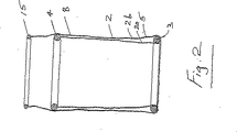
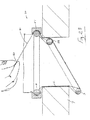
添付図面に関し、先ずその図1乃至図10には、スリーブ2により提供されるレトラクタ部材と、Oリングのような弾性材料からなる遠位側リング3により提供される遠位側部材と、同じくOリングであるような基端側リング4により提供される基端側部材とを有する器具1が示されている。
The invention can be more clearly understood from the several detailed description of several embodiments, given below by way of example only, with reference to the accompanying drawings, in which:
With reference to the accompanying drawings, first of all, FIGS. 1 to 10 show a retractor member provided by a
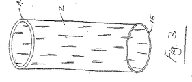
スリーブ2は、柔軟なプラスチックフィルム材料のような適当な材料で形成され、かつ本実施例では患者の腹腔7に形成された切開創6の中に挿入するための遠位側部分5と、切開創6から患者の外側に延長するための基端側部分8とを有する。
The
本実施例では、遠位側リングがスリーブ2に固定されず、むしろスリーブ2はリング3の周りに案内されて、幾分プーリのような手法で遠位側リング3に関して軸方向に自由に動くことができる。基端側リング4はスリーブ2に、本実施例ではその基端側内端部に固定されている。スリーブ2の端部は、本実施例ではつかみリング15により補強されたハンドルまたはつかみ部に至っている。
In this embodiment, the distal ring is not fixed to the
本発明によるレトラクタ器具を構成するために、スリーブ2には、先ずその一方の端部に固定されたつかみリング15と、他方の端部に固定された基端側リング4とが設けられる(図3,図4)。次に遠位側リング3を、図4及び図5に示すように、スリーブ2の上に配置する。次につかみリング15を用いて、つかみリング15が最も上になる図1及び図2の形態にスリーブ2を折り返すように、スリーブ2を扱う。前記スリーブは基端側リング4から延長し、かつ遠位側リング3はスリーブ2の内層2aと外層2bとの間に収容される。ここで、前記器具は使う準備ができる。
In order to construct a retractor device according to the invention, the
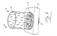
弾性を有する遠位側リング3を丸めて、図4に示すようにスリーブ2の遠位側端部5と共に切開創6の中に挿入する。次に、スリーブ2を図8乃至図10の矢印Aの向きに引き上げる。スリーブ2を引き上げると、外層2bが引っ張られ、内層2aが基端側リング3の周りに引き寄せられる。この結果、基端側リング4と遠位側リング3との間の軸方向の長さが短くなり、前記スリーブをピンと張らせて、切開創6の縁に開創力を作用させる。このシステムは、スリーブ2に張力が作用しかつ引張り力が解放されると、開創力が作用した状態でリング3,4が所定位置に維持されるので、セルフロック機構と考えられる。このセルフロックには、この形態における前記スリーブの内層及び外層間の摩擦係合が寄与している。
The elastic
前記切開創は開創されているとき、その縁は前記スリーブにより保護されている。開創時、例えば外科医がその手及び/または器具を挿入して処置を行うためのアクセスポートが提供される。前記器具は、切開手術におけるレトラクタ即ち開創器として、または腹腔鏡補助下手術においてバルブ/シールが使用できるようにするための、もしくは一般に器具や手のアクセスのためのベースとして使用することができる。 When the incision is being opened, its edge is protected by the sleeve. An access port is provided upon opening, for example, for the surgeon to insert the hand and / or instrument to perform the procedure. The instrument can be used as a retractor or retractor in open surgery, or to allow the use of a valve / seal in laparoscopic-assisted surgery, or generally as a base for instrument or hand access.
前記切開創の外側の余分なスリーブ部分20は、例えば切り離すことができる。
The
前記レトラクタはある範囲の大きさの切開創に適しており、かつ容易に製造することができる。また、使用時に扱うことが比較的容易である。これは開創するだけでなく切開創を保護する。 The retractor is suitable for a range of sized incisions and can be easily manufactured. Moreover, it is relatively easy to handle at the time of use. This not only opens but also protects the incision.
図11乃至図19に関し、図1乃至図10に関連して上述した器具に類似する、本発明による別の器具50が示され、類似の部分には同じ参照符号が付されている。この実施例では、前記器具が基端側リング4のためのガイド部材51を有する。ガイド部材51は、図示するようにリング4に適合する大きさの内向きのC字形溝52を有する環状リング部材の形態をなす。スリーブ2の外層は、リング4とガイド51との間に挟まれて、スリーブ2の引張りを更に制御し、それにより開創力の印加を更に制御している。また、ガイド51は、基端側リング4を安定化させるのに役立つ。器具50の使用方法が図12乃至図15に示されており、上述したそれと類似している。
With reference to FIGS. 11-19, another
リング51のようなあらゆる適当なガイドが、前記スリーブを引き上げて切開創を開創する際に基端側リング4を所望の位置に保持/安定化させるのに役立つように用いることができる。前記ガイドが、リング4の基端側に配置することができる。
Any suitable guide, such as
前記ガイド部材によって、バルブのような器具を取り付けることができるモニタ部材が提供される。 The guide member provides a monitor member to which an instrument such as a valve can be attached.
図16に関し、本実施例では余分なスリーブ部分20を切り離すことができることを示している。
With respect to FIG. 16, this embodiment shows that the
図17に関し、この実施例では、余分なスリーブ部分が切開創内にひっくり返されている。この形態では、器官レトラクタとして機能しまたは外科医に入り込むための開口を提供することができる。 With reference to FIG. 17, in this embodiment, the excess sleeve portion is turned over into the incision. In this form, it can function as an organ retractor or provide an opening for entry into the surgeon.
図18及び図19に関し、この実施例では、前記余分なスリーブ部分がねじられて、アイリス絞りバルブ65を形成している。
18 and 19, in this embodiment, the excess sleeve portion is twisted to form the
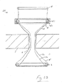
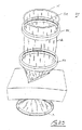
図20乃至図22に示される実施例では、本発明による器具70が一体型のシール/バルブ71を有する。器具70は、図11乃至図19に関連して上述したそれと類似しており、類似の部分には同じ参照符号が付されている。この実施例では、ガイド部材50が、図21に示されるようなつかみリング15を受けるための外側溝75を有する。余分なスリーブ部分20は外方下向きに折り返され、つかみリング15が溝75内に係合して、機密なシールを提供する。この形態では、膨張ポート76を介して前記余分なスリーブ部分を膨張させて、一体型のアクセスバルブ71を設けることができる(図22)。このバルブは、その中を通過する手、器具又は類似物と気密に係合するのに用いることができる。前記バルブを画定する膨張させたスリーブ部分は、その中に物体を通す際に反転させることができる。
In the embodiment shown in FIGS. 20-22, the instrument 70 according to the present invention has an integral seal /
図23乃至図28には、上述したレトラクタに類似する、本発明による別のレトラクタ80が示され、類似の部分には同じ参照符号が付されている。この実施例では、レトラクタ80が解放機構を有し、それは、本実施例では、一方の端部82において内側リング3に結合され、かつ他方の端部は外側の自由端83に至り、ユーザが手でつかむことができる解除ひも又はリボン81によって提供される。リボン81は、組立時に、基端側リング4と外側ガイド部材51との間の隙間を通すことにより、該リング4とガイド部材との間に配置される。リボン81は、切開創内に位置する使用形態において、セルフロックされたスリーブの解放を容易にする。リボン81を引張ることにより内側リング3を引張り、該リング3を前記切開創の内壁から解放できるようにし、それにより前記器具を解放する。この動作は、リング3の柔軟性によって容易になる。
FIGS. 23-28 show another
この構成の利点は、ユーザは前記器具をそのセルフロックされた開創形態から容易に解放できることである。 The advantage of this configuration is that the user can easily release the instrument from its self-locking retracted configuration.
図29乃至図33に関し、本発明による別の器具90が示され、上述した器具のそれと類似する部分には同じ参照符号が付されている。この実施例では、器具90が、基端側リング4のための下側ガイドリング51と、その間をスリーブ2が通る上側ガイドリング91及び第2基端側リング92により設けられる外側ガイドアセンブリとを有する。全ての関連する実施例において、リング91のような上側ガイドによって第2の取付部材が、同様に取付部材を提供するリング51のような第1のガイド部材の基端側に配置される。前記器具は、第一に上述したように切開創を開創するのに用いられる。この段階では、前記外側ガイドアセンブリがガイド部材51より基端側リング4の外側になると好都合である。実際、それは完全に分離し、かつ後で、図30に示すように切開創を開創したときのような適当な段階でスリーブ2に結合することができる。次に、前記外側ガイドアセンブリを下向きに、図31に示すように切開創に向けて動かす。これはスリーブ2を上向きに引張りながら実行することができる。前記外側ガイドアセンブリがガイド部材51付近にあるとき、図32に示すように、余分なスリーブ長さを切断することができる。ガイド部材51に関して前記ガイドアセンブリをねじることによって、スリーブ2がねじられ、スリーブ2の管腔を閉鎖し、かつ図33に示すようにアイリスタイプのアクセスバルブ95を形成する。このようにして、シールされたアクセスポートが、切開創を通した手及び/また器具のためのアクセスのために設けられる。
With reference to FIGS. 29-33, another instrument 90 according to the present invention is shown, with parts similar to those of the instrument described above having the same reference numerals. In this embodiment, the instrument 90 comprises a
外科医が作る切開創について言及してきたが、本発明の器具は、肉体の開口部のようなあらゆる開口の開創について適用できることが理解される。 While reference has been made to an incision made by a surgeon, it is understood that the instrument of the present invention is applicable to the opening of any opening, such as a physical opening.
図34及び図35に関し、図29乃至図33の器具に類似する、本発明による別のレトラクタ器具100が示され、類似の部分には同じ参照符号が付されている。この実施例では、解除可能なロックが設けられて、アクセスバルブ95を閉じた状態に維持している。相互に噛み合わせるために、本実施例では、上側ガイドリング91が下側ガイドリング51とのしまりばめである。ねじ込み式または差込型の係合手段や磁石、クリップ及びその類似物のような他の様々なロック機構を用いることができる。
With reference to FIGS. 34 and 35, another
図36乃至図41に関し、図29乃至図33の器具に類似する、本発明による別のレトラクタ器具110が示され、類似の部分には同じ参照符号が付されている。この実施例では、前記器具には、一体型のバルブを閉じた位置に付勢する付勢手段が組み込まれている。この付勢手段は、本実施例では、ガイドリング51,91間の前記スリーブの周囲に配置されるコイルばね111によって提供される。使用時には、前記器具は、上側ガイドリング91を下向きに動かす際に、ばね111が同じく下向きに下側ガイドリング51に向けて、最初は図38に示す位置まで動くことを除いて、図29乃至図33の器具と同様にして使用される。この段階で、余分なスリーブ材料を取り除くことができる。ばね111は、上側リング91を下向きに押しながら該上側リング91を回転させるにつれて緊張する。2つのリング51、91間のスリーブ材料がねじられて、図39に示すようにアイリスタイプのバルブ112を開けて、その中に器具、手、腕または類似物のような物体を通すために、前記ばねの付勢力に抗して下向きの力を印加し、上側リング91を下側リング51に向けて押す。この形態が図40に示されている。物体を挿入したとき、上側リング91が解放され、バルブを物体の周囲に閉じることができる。器具110の操作は、図41(a)乃至図41(d)から直ちに明らかである。図41(a)では、閉じた静止した形態のバルブ112が示されている。図41(b)は、バルブ112を開く下向きの力が作用している状態を示している。図41(c)には、開いたバルブ112の中に挿入された器具113のような物体が示されている。図41(d)には、上側リング91への下向きの圧力が解放されて、バルブ112が物体113の周囲に閉じ得るようになっている。
With reference to FIGS. 36-41, another
図42乃至図45に関し、図11乃至図18の器具に類似するいくつかの側面を有する、本発明による別の器具120が示され、類似の部分には同じ参照符号が付されている。この実施例では、前記器具がリップシール121を有する。リップシール121は、その中に器具のような物体123を通す中央孔122を有する膜によって提供される。リップシール121は、基端側に柔軟なスリーブ部分125が提供されるように、ガイドリング51の基端側のスリーブに上に配置される。このスリーブ部分125は、図45に示すように、物体123のオフセット動作を容易にする点で非常に有用である。スリーブ部分125は、リップシール121と物体123との間のシール係合を維持しつつ、物体123の動きに適応する。この特徴は、上述した他のいくつかの特徴と共に、添付図面に示したもの以外に一般に創傷プロテクタ/レトラクタ及びアクセス部品の他の構造と関連して用いられることが分かる。
With reference to FIGS. 42-45, there is shown another instrument 120 according to the present invention having several aspects similar to the instrument of FIGS. 11-18, wherein like parts are labeled with the same reference numerals. In this embodiment, the instrument has a
図46乃至図48には、図11乃至図15のそれに類似するいくつかの特徴を有する、本発明による別の器具130が示され、類似の部分には同じ参照符号が付されている。この実施例では、前記スリーブが、前記器具が開創形態にあるとき、創傷の外側に基端側部分を有する。この基端側スリーブ部分は、ガイドリング51から延長する第1部分131と、第1部分131から延長する第2部分132とを有する。第2部分132は、2つの離隔されたアイリスリング134、135の間に画定される。アイリスリング134、135は、組み立て時に相互に係合するための突起及び溝のような係合の特徴を有することが分かる。また、アイリスリング134は、本実施例では突起138により提供されるガイドリング51の対応する係合要素と組み立て時に係合するための、本実施例では溝137により提供される係合要素を有する。
46-48 show another instrument 130 according to the present invention having some features similar to that of FIGS. 11-15, with like parts having the same reference numerals. In this embodiment, the sleeve has a proximal portion outside the wound when the device is in a retracted configuration. The proximal sleeve portion has a first portion 131 extending from the
前記器具は、上述したように、第1及び第2スリーブ部分131、132を基端側に延長させたまま、切開創を開創するのに適している。第1スリーブ部分131は余分なものであり、図48に示すように第1アイリスリング134をガイドリング138に組み立てた時に取り除き、又は丸めることができる。次に、第2即ち上側アイリスリング135を回転させてスリーブ部分132をねじり、図49に示すようにアイリスタイプのシールを形成する。アイリスリング135は、図示するようにアイリスリング134と係合して、前記バルブを閉じた状態に維持する。
As described above, the instrument is suitable for opening an incision while the first and
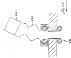
上述したいくつかの実施例では、バルブ829がレトラクタベース811に直接取り付られている。レトラクタ811とバルブ829との間に柔軟な継手を設けることが可能である。例えば、図93及び図94に示すように、このような柔軟な継手は、レトラクタ811とバルブ829との間を延長する所定長さの柔軟なスリーブ830によって提供されす。柔軟なスリーブ830は、バルブ829に取付られた余分なレトラクタスリーブ材料で形成することができる。
In some embodiments described above, the valve 829 is directly attached to the
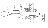
本発明の更に別の実施例では、図52乃至図57に示すように、バルブ860がレトラクタ811と、それらの間の柔軟な継手を容易にするように結合されている。例えば、固定された長さのスリーブ862が、レトラクタ811の外側基端側リング863とバルブ860との間を延長している。レトラクタ811からの余分なスリーブ材料864は、バルブ860の中を上に抜けることができる。バルブ860を押し下げて、余分なスリーブを引き上げ、レトラクタベース811を切開創内にしっかりと固定することができる。余分なスリーブ材料864は、必要により切除しかつ取り除くことができる。柔軟なスリーブ864によって、器具/物体814の軸へのバルブシールを傷つけることなく、図57に示すように器具を傾けることができる。
In yet another embodiment of the invention, as shown in FIGS. 52-57, a
図58及び図59に示すように、ばね867を、より柔軟性を制御するために、バルブ860とレトラクタの基端側リング863との間に設けることができる。
As shown in FIGS. 58 and 59, a
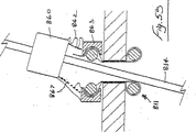
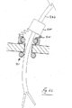
図60乃至図62には、バルブ870をレトラクタ811に解除可能に取り付けた別のモジュラシステムが示されている。レトラクタ811は、バルブ870を受ける凹み872を設けた基端側リング871を有する。器具の軸814は、容易にバルブ870及びレトラクタ811の中を通すことができる。少なくとも軸814の部分873は、前記レトラクタの略直ぐ遠位側で曲げられ又は向きをとることができる。
60 to 62 show another modular system in which the
次に図63乃至図66では、レトラクタ111からの余分なスリーブ材料881を用いて、レトラクタ811にあらゆる適当なバルブ880を結合することができる。バルブ880は引き上げてレトラクタベース811を配置することができる。余分なスリーブ材料881によって、曲がった軸を有するようなものでさえ、器具883のような物体の簡単な導入を容易にする柔軟なネック部が提供される(図119)。図120に示すように、このような構造は、バルブ880をレトラクタベース811により近く動かすことができるようにすることによって、追加の器具を伸ばすことを容易にしている。
Next, in FIGS. 63-66, any
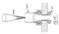
図67乃至図72には、創傷プロテクタ及びレトラクタ器具811及びバルブ900からなる別のアクセスポートが示されている。バルブ900は、本実施例では、幾分折り曲げ可能な飲用ストローの折り曲げ可能なヒンジ部分のようにして波形の形態を有する可鍛性材料で形成されたスリーブ902によりレトラクタ器具811の外側ガイドリング901に結合されている。スリーブ902は、前記レトラクタの長手方向軸からオフセットするように予め形成し、器具又は類似物の挿入を簡単にすることができる。波形スリーブ902は、図68に示すように圧縮して姿勢を低くし、図69及び図70に示すように、余分なレトラクタスリーブの輪郭をはっきりさせることを容易にすることができる。その後、波形スリーブ902を延長/長大化させることができ、かつ所望の形態に容易に操ることができる。スリーブ902は可鍛性を有するので、腹腔に圧力をかけた時でさえ、所望の曲げ形状が保持される。全ての余分なレトラクタスリーブ材料905は、図示するように切除し、又は上述したように用いることができる。これに関連して、用語「可鍛性」は、所望の位置及び/又は向きに操ることができる、及びこの操られた位置及び/又は向きを、例えば腹腔鏡器具の部分挿入の際に患者に所期の目的で使用する際に印加する一般的な圧力や張力の下で維持する要素を指称するのに用いられる。
67-72 show another access port consisting of a wound protector and
本実施例のアクセスポートは、多くの方法で用いることができる。ある方法では、前記レトラクタを上述したように使用し、遠位側の内側リングを切開創内に挿入し、外側リングを滑らせて、切開創を放射方向に制御しながら拡張させる。次に前記レトラクタを所定位置に固定することができる。必要な場合には、外側リングを更に下向きに動かして、より大きな切開創を作ることができる。 The access port of this embodiment can be used in many ways. In one method, the retractor is used as described above, the distal inner ring is inserted into the incision, and the outer ring is slid to expand the incision in a radially controlled manner. The retractor can then be fixed in place. If necessary, the outer ring can be moved further downward to create a larger incision.
いくつかの構成では、器具を肉体の外側で手で曲げることができ、かつ曲げた器具をアクセスポートの中に送って、容易に術野にアクセスすることができる。 In some configurations, the instrument can be bent by hand outside the body, and the bent instrument can be routed into the access port for easy access to the surgical field.
更に別の実施例では、器具をアクセスポート内に挿入し、かつ外科医が腹壁自体を用いて器具を曲げ、かつ次に曲げた部分を更に腹腔内に挿入する。 In yet another embodiment, the instrument is inserted into the access port, and the surgeon uses the abdominal wall itself to bend the instrument and then insert the bent portion further into the abdominal cavity.
全ての場合において、前記スリーブはバルブ又はそれに取り付けられた他の要素をつかむことによってつかむことができる。 In all cases, the sleeve can be grasped by grasping a valve or other element attached thereto.
本発明のアクセスポートは、次の利点の少なくともいくつかを有する。
放射方向への拡張の制御
1.より小さな切開創を用いたより大きなアクセス
2.必要に応じて(例えば、開腹術(lap coli.)の際の検体の除去)切開創の大きさを変更できる
より大きなシール機能
1.創縁からのガス漏れがない
2.切開創から不用意に取り出すことができない
3.あらゆる切開創をシールし、二次的なシール方法(縫合、ハッソン(Hasson)ポート等)を全く必要としない
腹腔内輪郭の削除
1.腹腔内により多くの作業空間を取り戻す(骨盤手術において重要)
2.根治的前立腺切除術のような手術のための会陰部アクセス
感染及び癌の播種からの創傷の保護
1.「組み煙突」作用の無い密なシール
2.取り外し時に潜在的な汚染の全領域が切開創から分離される
腹腔外輪郭の減少
1.器具の有効作業長さを増加する
2.腹腔外でのより大きな作業領域
従来の腹腔鏡器具の動作自由度の増加
The access port of the present invention has at least some of the following advantages.
Control of
Delete intra-abdominal contours Regain more work space in the abdominal cavity (important for pelvic surgery)
2. Perineal access for surgery such as radical prostatectomy
Protection of wounds from infection and
Reduction of
Increased freedom of movement of conventional laparoscopic instruments
本発明は、添付図面に関連して上述した実施例に限定されるものでなく、その構造及び詳細な部分において様々に変更することができる。 The present invention is not limited to the embodiments described above with reference to the accompanying drawings, but can be variously modified in structure and details.
Claims (17)
遠位側部材と、
基端側部材と、
少なくとも前記遠位側部材と前記基端側部材との間を延長するスリーブと、
前記スリーブの基端側部分のためのガイド部材とを備え、
前記スリーブが、前記基端側部材から遠位側に前記遠位側部材へと延長し、前記遠位側部材の周りを延長し、前記遠位側部材から基端側へ延長し、かつ前記ガイド部材と前記基端側部材との間を延長する戻り部分を有し、前記スリーブが、第1端部において前記基端側部材に固定され、かつ前記戻り部分において前記基端側部材に対して軸方向に滑らせることができ、前記戻り部分によって、前記スリーブを上向きに引き上げて前記遠位側部材と前記基端側部材との間に配置される軸方向の長さを短くするための基端側つかみ部が提供されることを特徴とする創傷プロテクタ及びレトラクタ器具。A longitudinal axis;
A distal member;
A proximal member;
A sleeve extending between at least the distal member and the proximal member ;
A guide member for a proximal side portion of the sleeve ,
The sleeve extends distally from the proximal member to the distal member, extends around the distal member, extends from the distal member to the proximal side, and A return portion extending between the guide member and the proximal end member; the sleeve is fixed to the proximal end member at a first end; and The return portion for pulling up the sleeve upward to shorten the axial length disposed between the distal member and the proximal member . A wound protector and retractor device, characterized in that a proximal grip is provided .
Applications Claiming Priority (4)
| Application Number | Priority Date | Filing Date | Title |
|---|---|---|---|
| US41578002P | 2002-10-04 | 2002-10-04 | |
| US42821502P | 2002-11-22 | 2002-11-22 | |
| US49090903P | 2003-07-30 | 2003-07-30 | |
| PCT/IE2003/000141 WO2004030547A1 (en) | 2002-10-04 | 2003-10-06 | A wound retractor device |
Related Child Applications (1)
| Application Number | Title | Priority Date | Filing Date |
|---|---|---|---|
| JP2009269354A Division JP2010069316A (en) | 2002-10-04 | 2009-11-26 | Wound retractor device |
Publications (2)
| Publication Number | Publication Date |
|---|---|
| JP2006501973A JP2006501973A (en) | 2006-01-19 |
| JP4505643B2 true JP4505643B2 (en) | 2010-07-21 |
Family
ID=32074375
Family Applications (2)
| Application Number | Title | Priority Date | Filing Date |
|---|---|---|---|
| JP2005500081A Expired - Fee Related JP4505643B2 (en) | 2002-10-04 | 2003-10-06 | Wound retractor device |
| JP2009269354A Pending JP2010069316A (en) | 2002-10-04 | 2009-11-26 | Wound retractor device |
Family Applications After (1)
| Application Number | Title | Priority Date | Filing Date |
|---|---|---|---|
| JP2009269354A Pending JP2010069316A (en) | 2002-10-04 | 2009-11-26 | Wound retractor device |
Country Status (9)
| Country | Link |
|---|---|
| EP (2) | EP1545348B1 (en) |
| JP (2) | JP4505643B2 (en) |
| AT (1) | ATE400226T1 (en) |
| AU (1) | AU2003272042A1 (en) |
| BR (1) | BR0315045A (en) |
| CA (1) | CA2499835A1 (en) |
| DE (1) | DE60322083D1 (en) |
| MX (1) | MXPA05003554A (en) |
| WO (1) | WO2004030547A1 (en) |
Families Citing this family (50)
| Publication number | Priority date | Publication date | Assignee | Title |
|---|---|---|---|---|
| US7537564B2 (en) | 1998-12-01 | 2009-05-26 | Atropos Limited | Wound retractor device |
| US8465494B2 (en) | 1998-12-01 | 2013-06-18 | Atropos Limited | Apparatus for inserting a surgical device at least partially through a wound opening |
| US7559893B2 (en) | 1998-12-01 | 2009-07-14 | Atropos Limited | Wound retractor device |
| AU7813100A (en) | 1999-10-14 | 2001-04-23 | Atropos Limited | A wound retractor |
| EP1326524B1 (en) | 2000-10-19 | 2010-09-01 | Applied Medical Resources Corporation | Surgical access apparatus and method |
| JP4324471B2 (en) | 2001-08-14 | 2009-09-02 | アプライド メディカル リソーシーズ コーポレイション | Access path sealing device |
| EP2343031B1 (en) | 2002-06-05 | 2013-08-07 | Applied Medical Resources Corporation | Wound retractor |
| US9271753B2 (en) | 2002-08-08 | 2016-03-01 | Atropos Limited | Surgical device |
| ES2287516T3 (en) | 2002-09-19 | 2007-12-16 | Atropos Limited | WOUND RETRACTOR SYSTEM. |
| US20050020884A1 (en) | 2003-02-25 | 2005-01-27 | Hart Charles C. | Surgical access system |
| WO2005013803A2 (en) | 2003-08-06 | 2005-02-17 | Applied Medical Resources Corporation | Surgical device with tack-free gel and method of manufacture |
| US7425202B2 (en) * | 2004-03-05 | 2008-09-16 | Percutaneous Systems, Inc. | Non-seeding biopsy device and method |
| WO2006040748A1 (en) * | 2004-10-11 | 2006-04-20 | Atropos Limited | An instrument access device |
| EP1861022A2 (en) * | 2005-03-22 | 2007-12-05 | Atropos Limited | A surgical instrument |
| JP2009501045A (en) | 2005-07-15 | 2009-01-15 | アトロポス・リミテッド | Wound retractor |
| AU2006304141B2 (en) | 2005-10-14 | 2012-07-05 | Applied Medical Resources Corporation | Gel cap for wound retractor |
| US8231527B2 (en) | 2006-07-18 | 2012-07-31 | Ethicon Endo-Surgery, Inc. | Roll-up wound protector with asymmetric ring |
| US7749161B2 (en) | 2006-12-01 | 2010-07-06 | Ethicon Endo-Surgery, Inc. | Hand assisted laparoscopic device |
| US7922656B2 (en) | 2007-04-04 | 2011-04-12 | Ethicon Endo-Surgery, Inc. | Hand assisted laparoscopic seal assembly with detachable attachment ring |
| JP5441890B2 (en) | 2007-05-11 | 2014-03-12 | アプライド メディカル リソーシーズ コーポレイション | Surgical retractor with gel pad |
| US8657740B2 (en) | 2007-06-05 | 2014-02-25 | Atropos Limited | Instrument access device |
| EP2152175B1 (en) | 2007-06-05 | 2015-10-28 | Atropos Limited | An instrument access device |
| US8465515B2 (en) | 2007-08-29 | 2013-06-18 | Ethicon Endo-Surgery, Inc. | Tissue retractors |
| US8273017B1 (en) | 2007-10-30 | 2012-09-25 | Ethicon Endo-Surgery, Inc. | Surgical access port with ring actuated latching mechanism |
| US8142354B1 (en) | 2007-10-30 | 2012-03-27 | Ethicon Endo-Surgery, Inc. | Laminated surgical access port |
| US8517931B2 (en) | 2007-11-26 | 2013-08-27 | Ethicon Endo-Surgery, Inc. | Tissue retractors |
| US8128559B2 (en) | 2007-11-26 | 2012-03-06 | Ethicon Endo-Surgery, Inc. | Tissue retractors |
| ES2659871T3 (en) | 2008-10-13 | 2018-03-19 | Applied Medical Resources Corporation | Single track access system |
| US8147405B2 (en) | 2008-10-30 | 2012-04-03 | Ethicon Endo-Surgery, Inc. | Surgical access port with multilayered tortuous path seal |
| US8375955B2 (en) | 2009-02-06 | 2013-02-19 | Atropos Limited | Surgical procedure |
| US8257251B2 (en) | 2009-04-08 | 2012-09-04 | Ethicon Endo-Surgery, Inc. | Methods and devices for providing access into a body cavity |
| WO2011033495A1 (en) | 2009-09-17 | 2011-03-24 | Atropos Limited | An instrument access device |
| US8926504B2 (en) * | 2010-10-01 | 2015-01-06 | Covidien Lp | Access assembly |
| AU2011308636B2 (en) | 2010-10-01 | 2015-06-04 | Applied Medical Resources Corporation | Surgical access port system |
| US9289115B2 (en) | 2010-10-01 | 2016-03-22 | Applied Medical Resources Corporation | Natural orifice surgery system |
| US8668641B2 (en) * | 2011-03-30 | 2014-03-11 | Covidien, LP | Surgical access assembly with sleeve and adjustable fastener |
| EP4104774A1 (en) | 2011-05-10 | 2022-12-21 | Applied Medical Resources Corporation | Wound retractor |
| WO2013010107A2 (en) | 2011-07-13 | 2013-01-17 | Cook Medical Technologies Llc | Surgical retractor device |
| US20130225932A1 (en) * | 2012-02-23 | 2013-08-29 | Covidien Lp | Multi-portion wound protector |
| US9320861B2 (en) | 2013-02-21 | 2016-04-26 | Covidien Lp | Smoke vent for access port device |
| US9421034B2 (en) | 2013-03-15 | 2016-08-23 | Applied Medical Resources Corporation | Trocar surgical seal |
| KR102300866B1 (en) | 2013-03-15 | 2021-09-13 | 어플라이드 메디컬 리소시스 코포레이션 | Mechanical gel surgical access device |
| US9775591B2 (en) * | 2013-11-21 | 2017-10-03 | Edwards Lifesciences Corporation | Sealing devices and related delivery apparatuses |
| CA2952640C (en) | 2014-07-18 | 2023-04-04 | Applied Medical Resources Corporation | Gels having permanent tack free coatings and method of manufacture |
| KR102509415B1 (en) | 2014-08-15 | 2023-03-10 | 어플라이드 메디컬 리소시스 코포레이션 | Natural orifice surgery system |
| EP3223718A2 (en) | 2014-11-25 | 2017-10-04 | Applied Medical Resources Corporation | Circumferential wound retraction with support and guidance structures |
| KR102632231B1 (en) | 2015-04-23 | 2024-02-01 | 어플라이드 메디컬 리소시스 코포레이션 | Systems and methods for tissue removal |
| ES2836282T3 (en) | 2015-09-15 | 2021-06-24 | Applied Med Resources | Surgical robotic access system |
| AU2016335864B2 (en) * | 2015-10-07 | 2021-05-20 | Applied Medical Resources Corporation | Wound retractor with multi-segment outer ring |
| AU2017324450B2 (en) | 2016-09-12 | 2022-09-29 | Applied Medical Resources Corporation | Surgical robotic access system for irregularly shaped robotic actuators and associated robotic surgical instruments |
Family Cites Families (9)
| Publication number | Priority date | Publication date | Assignee | Title |
|---|---|---|---|---|
| US5514133A (en) * | 1994-08-26 | 1996-05-07 | Golub; Robert | Access device for endoscopic surgery |
| US6440063B1 (en) * | 1997-04-30 | 2002-08-27 | University Of Massachusetts | Surgical access port and laparoscopic surgical method |
| US5906577A (en) * | 1997-04-30 | 1999-05-25 | University Of Massachusetts | Device, surgical access port, and method of retracting an incision into an opening and providing a channel through the incision |
| IL143179A0 (en) * | 1998-12-01 | 2002-04-21 | Atropos Ltd | A surgical device for retracting and/or sealing an incision |
| ATE262304T1 (en) * | 1998-12-01 | 2004-04-15 | Atropos Ltd | LAPAROSCOPIC SEALED ACCESS DEVICE |
| JP2001340346A (en) * | 1999-06-08 | 2001-12-11 | Sumitomo Bakelite Co Ltd | Medical treatment instrument |
| US6171282B1 (en) * | 1999-07-23 | 2001-01-09 | Edgar K. Ragsdale | Soft cannula and methods for use |
| IE990795A1 (en) * | 1999-07-30 | 2001-03-07 | Gaya Ltd | Hand Access Port Device |
| AU7813100A (en) * | 1999-10-14 | 2001-04-23 | Atropos Limited | A wound retractor |
-
2003
- 2003-10-06 WO PCT/IE2003/000141 patent/WO2004030547A1/en active IP Right Grant
- 2003-10-06 JP JP2005500081A patent/JP4505643B2/en not_active Expired - Fee Related
- 2003-10-06 MX MXPA05003554A patent/MXPA05003554A/en active IP Right Grant
- 2003-10-06 CA CA002499835A patent/CA2499835A1/en not_active Abandoned
- 2003-10-06 EP EP03753883A patent/EP1545348B1/en not_active Expired - Lifetime
- 2003-10-06 EP EP08011478A patent/EP1987791A3/en not_active Withdrawn
- 2003-10-06 AU AU2003272042A patent/AU2003272042A1/en not_active Abandoned
- 2003-10-06 BR BR0315045-3A patent/BR0315045A/en not_active IP Right Cessation
- 2003-10-06 AT AT03753883T patent/ATE400226T1/en not_active IP Right Cessation
- 2003-10-06 DE DE60322083T patent/DE60322083D1/en not_active Expired - Lifetime
-
2009
- 2009-11-26 JP JP2009269354A patent/JP2010069316A/en active Pending
Also Published As
| Publication number | Publication date |
|---|---|
| CA2499835A1 (en) | 2004-04-15 |
| AU2003272042A1 (en) | 2004-04-23 |
| EP1545348B1 (en) | 2008-07-09 |
| JP2006501973A (en) | 2006-01-19 |
| WO2004030547A1 (en) | 2004-04-15 |
| EP1545348A1 (en) | 2005-06-29 |
| MXPA05003554A (en) | 2005-09-30 |
| DE60322083D1 (en) | 2008-08-21 |
| ATE400226T1 (en) | 2008-07-15 |
| EP1987791A2 (en) | 2008-11-05 |
| JP2010069316A (en) | 2010-04-02 |
| BR0315045A (en) | 2005-08-23 |
| EP1987791A3 (en) | 2008-11-19 |
Similar Documents
| Publication | Publication Date | Title |
|---|---|---|
| JP4505643B2 (en) | Wound retractor device | |
| US10278688B2 (en) | Wound retractor device | |
| EP1572014B1 (en) | A surgical device | |
| US7540839B2 (en) | Wound retractor | |
| US20050192483A1 (en) | Device | |
| US9277908B2 (en) | Retractor | |
| US9307976B2 (en) | Wound retractor | |
| EP1125552A1 (en) | Surgical retractor | |
| US20060149137A1 (en) | Easily placeable and removable wound retractor | |
| JP2002325769A (en) | Tool for medical treatment | |
| IE20030737A1 (en) | A wound retractor device | |
| IE20030945A1 (en) | A surgical access device | |
| IE20040521A1 (en) | A cannula |
Legal Events
| Date | Code | Title | Description |
|---|---|---|---|
| A621 | Written request for application examination |
Free format text: JAPANESE INTERMEDIATE CODE: A621 Effective date: 20060728 |
|
| A131 | Notification of reasons for refusal |
Free format text: JAPANESE INTERMEDIATE CODE: A131 Effective date: 20090526 |
|
| A601 | Written request for extension of time |
Free format text: JAPANESE INTERMEDIATE CODE: A601 Effective date: 20090825 |
|
| A521 | Request for written amendment filed |
Free format text: JAPANESE INTERMEDIATE CODE: A523 Effective date: 20091029 |
|
| A521 | Request for written amendment filed |
Free format text: JAPANESE INTERMEDIATE CODE: A523 Effective date: 20091126 |
|
| A602 | Written permission of extension of time |
Free format text: JAPANESE INTERMEDIATE CODE: A602 Effective date: 20090917 |
|
| A01 | Written decision to grant a patent or to grant a registration (utility model) |
Free format text: JAPANESE INTERMEDIATE CODE: A01 Effective date: 20100112 |
|
| A61 | First payment of annual fees (during grant procedure) |
Free format text: JAPANESE INTERMEDIATE CODE: A61 Effective date: 20100205 |
|
| A61 | First payment of annual fees (during grant procedure) |
Free format text: JAPANESE INTERMEDIATE CODE: A61 Effective date: 20100408 |
|
| FPAY | Renewal fee payment (event date is renewal date of database) |
Free format text: PAYMENT UNTIL: 20130514 Year of fee payment: 3 |
|
| R150 | Certificate of patent or registration of utility model |
Free format text: JAPANESE INTERMEDIATE CODE: R150 |
|
| FPAY | Renewal fee payment (event date is renewal date of database) |
Free format text: PAYMENT UNTIL: 20130514 Year of fee payment: 3 |
|
| R250 | Receipt of annual fees |
Free format text: JAPANESE INTERMEDIATE CODE: R250 |
|
| R250 | Receipt of annual fees |
Free format text: JAPANESE INTERMEDIATE CODE: R250 |
|
| R250 | Receipt of annual fees |
Free format text: JAPANESE INTERMEDIATE CODE: R250 |
|
| R250 | Receipt of annual fees |
Free format text: JAPANESE INTERMEDIATE CODE: R250 |
|
| R250 | Receipt of annual fees |
Free format text: JAPANESE INTERMEDIATE CODE: R250 |
|
| LAPS | Cancellation because of no payment of annual fees |