JP4503799B2 - Optical position measuring device - Google Patents
Optical position measuring device Download PDFInfo
- Publication number
- JP4503799B2 JP4503799B2 JP2000261121A JP2000261121A JP4503799B2 JP 4503799 B2 JP4503799 B2 JP 4503799B2 JP 2000261121 A JP2000261121 A JP 2000261121A JP 2000261121 A JP2000261121 A JP 2000261121A JP 4503799 B2 JP4503799 B2 JP 4503799B2
- Authority
- JP
- Japan
- Prior art keywords
- scale
- detection
- projection
- graduation
- position measuring
- Prior art date
- Legal status (The legal status is an assumption and is not a legal conclusion. Google has not performed a legal analysis and makes no representation as to the accuracy of the status listed.)
- Expired - Fee Related
Links
- 230000003287 optical effect Effects 0.000 title claims description 34
- 238000001514 detection method Methods 0.000 claims abstract description 100
- 238000005259 measurement Methods 0.000 claims abstract description 18
- 230000001419 dependent effect Effects 0.000 claims abstract description 8
- 230000000737 periodic effect Effects 0.000 claims description 13
- 230000009471 action Effects 0.000 claims description 5
- 230000004907 flux Effects 0.000 claims description 5
- 238000006073 displacement reaction Methods 0.000 claims 1
- 230000003993 interaction Effects 0.000 claims 1
- PNDPGZBMCMUPRI-UHFFFAOYSA-N iodine Chemical compound II PNDPGZBMCMUPRI-UHFFFAOYSA-N 0.000 claims 1
- 230000005540 biological transmission Effects 0.000 abstract description 11
- 230000005693 optoelectronics Effects 0.000 abstract description 2
- 238000005286 illumination Methods 0.000 description 7
- 239000000758 substrate Substances 0.000 description 6
- 238000010586 diagram Methods 0.000 description 5
- 238000000034 method Methods 0.000 description 3
- 239000004065 semiconductor Substances 0.000 description 3
- 238000004519 manufacturing process Methods 0.000 description 2
- 230000004048 modification Effects 0.000 description 2
- 238000012986 modification Methods 0.000 description 2
- 230000035945 sensitivity Effects 0.000 description 2
- VYZAMTAEIAYCRO-UHFFFAOYSA-N Chromium Chemical compound [Cr] VYZAMTAEIAYCRO-UHFFFAOYSA-N 0.000 description 1
- 229910004298 SiO 2 Inorganic materials 0.000 description 1
- 229910010413 TiO 2 Inorganic materials 0.000 description 1
- 238000004458 analytical method Methods 0.000 description 1
- 230000015572 biosynthetic process Effects 0.000 description 1
- 238000004364 calculation method Methods 0.000 description 1
- 238000006243 chemical reaction Methods 0.000 description 1
- 229910052804 chromium Inorganic materials 0.000 description 1
- 239000011651 chromium Substances 0.000 description 1
- 230000001143 conditioned effect Effects 0.000 description 1
- 238000011109 contamination Methods 0.000 description 1
- 230000000694 effects Effects 0.000 description 1
- 238000011156 evaluation Methods 0.000 description 1
- 239000011521 glass Substances 0.000 description 1
- 238000003384 imaging method Methods 0.000 description 1
- 239000000463 material Substances 0.000 description 1
- 229910052751 metal Inorganic materials 0.000 description 1
- 239000002184 metal Substances 0.000 description 1
- 230000010363 phase shift Effects 0.000 description 1
- 230000009467 reduction Effects 0.000 description 1
- 230000001629 suppression Effects 0.000 description 1
Images


Classifications
-
- G—PHYSICS
- G01—MEASURING; TESTING
- G01D—MEASURING NOT SPECIALLY ADAPTED FOR A SPECIFIC VARIABLE; ARRANGEMENTS FOR MEASURING TWO OR MORE VARIABLES NOT COVERED IN A SINGLE OTHER SUBCLASS; TARIFF METERING APPARATUS; MEASURING OR TESTING NOT OTHERWISE PROVIDED FOR
- G01D5/00—Mechanical means for transferring the output of a sensing member; Means for converting the output of a sensing member to another variable where the form or nature of the sensing member does not constrain the means for converting; Transducers not specially adapted for a specific variable
- G01D5/26—Mechanical means for transferring the output of a sensing member; Means for converting the output of a sensing member to another variable where the form or nature of the sensing member does not constrain the means for converting; Transducers not specially adapted for a specific variable characterised by optical transfer means, i.e. using infrared, visible, or ultraviolet light
- G01D5/32—Mechanical means for transferring the output of a sensing member; Means for converting the output of a sensing member to another variable where the form or nature of the sensing member does not constrain the means for converting; Transducers not specially adapted for a specific variable characterised by optical transfer means, i.e. using infrared, visible, or ultraviolet light with attenuation or whole or partial obturation of beams of light
- G01D5/34—Mechanical means for transferring the output of a sensing member; Means for converting the output of a sensing member to another variable where the form or nature of the sensing member does not constrain the means for converting; Transducers not specially adapted for a specific variable characterised by optical transfer means, i.e. using infrared, visible, or ultraviolet light with attenuation or whole or partial obturation of beams of light the beams of light being detected by photocells
- G01D5/36—Forming the light into pulses
- G01D5/38—Forming the light into pulses by diffraction gratings
-
- G—PHYSICS
- G01—MEASURING; TESTING
- G01D—MEASURING NOT SPECIALLY ADAPTED FOR A SPECIFIC VARIABLE; ARRANGEMENTS FOR MEASURING TWO OR MORE VARIABLES NOT COVERED IN A SINGLE OTHER SUBCLASS; TARIFF METERING APPARATUS; MEASURING OR TESTING NOT OTHERWISE PROVIDED FOR
- G01D5/00—Mechanical means for transferring the output of a sensing member; Means for converting the output of a sensing member to another variable where the form or nature of the sensing member does not constrain the means for converting; Transducers not specially adapted for a specific variable
- G01D5/26—Mechanical means for transferring the output of a sensing member; Means for converting the output of a sensing member to another variable where the form or nature of the sensing member does not constrain the means for converting; Transducers not specially adapted for a specific variable characterised by optical transfer means, i.e. using infrared, visible, or ultraviolet light
- G01D5/32—Mechanical means for transferring the output of a sensing member; Means for converting the output of a sensing member to another variable where the form or nature of the sensing member does not constrain the means for converting; Transducers not specially adapted for a specific variable characterised by optical transfer means, i.e. using infrared, visible, or ultraviolet light with attenuation or whole or partial obturation of beams of light
- G01D5/34—Mechanical means for transferring the output of a sensing member; Means for converting the output of a sensing member to another variable where the form or nature of the sensing member does not constrain the means for converting; Transducers not specially adapted for a specific variable characterised by optical transfer means, i.e. using infrared, visible, or ultraviolet light with attenuation or whole or partial obturation of beams of light the beams of light being detected by photocells
- G01D5/347—Mechanical means for transferring the output of a sensing member; Means for converting the output of a sensing member to another variable where the form or nature of the sensing member does not constrain the means for converting; Transducers not specially adapted for a specific variable characterised by optical transfer means, i.e. using infrared, visible, or ultraviolet light with attenuation or whole or partial obturation of beams of light the beams of light being detected by photocells using displacement encoding scales
- G01D5/34776—Absolute encoders with analogue or digital scales
- G01D5/34792—Absolute encoders with analogue or digital scales with only digital scales or both digital and incremental scales
- G01D5/34794—Optical encoders using the Vernier principle, i.e. incorporating two or more tracks having a (n, n+1, ...) relationship
Landscapes
- Physics & Mathematics (AREA)
- General Physics & Mathematics (AREA)
- Optical Transform (AREA)
- Length Measuring Devices By Optical Means (AREA)
- Body Structure For Vehicles (AREA)
- Vehicle Body Suspensions (AREA)
- Eye Examination Apparatus (AREA)
Abstract
Description
【0001】
【発明の属する技術分野】
本発明は、2つの互いに移動可能な対象物の精密な相対位置の決定のために好適な光学的位置測定装置に関する。
【0002】
【従来の技術】
公知の位置測定装置は、目盛板としての走査される目盛構造並びにこれに対して測定方向に移動可能で、光源、1つ又は複数の他の目盛構造と検出装置とを備えた走査ユニットとを有する。位置に依存する走査信号の発生は、ここで興味のある位置測定装置における次に説明する基本原理をベースとする。1つ又は複数の第1目盛構造によってそのような位置測定装置で1つ又は複数の第2目盛構造によって走査信号の発生のために走査される微細な縞模様が発生する。最も簡単な場合、そのような位置測定装置では、第1目盛構造が少なくとも1つのコリメートされた光源によって照射されるいわゆる2格子−発信器が対象とされる。次の第2目盛構造上に光模様が生じ、その際第2目盛構造の目盛周期が光模様の目盛周期と一致する。両目盛構造の相対移動の場合に、第2目盛構造を通る光線の周期的な変調が生じる。第2目盛構造の後方に配置されたオプトエレクトロニック検出要素を介してこれらの変調された光束が検出される。前記の例で説明したように、第1及び第2目盛構造の機能的作用に基づいて、第1目盛構造を次に投影目盛と称する。これに対して第2目盛構造は検出目盛と称する。
【0003】
位相のずれた複数の走査信号の発生のために、そのような位置測定装置において、度々検出目盛及び投影目盛の目盛周期を互いに僅かに相違するように選択することが行われる。この場合検出目盛から検出目盛の目盛線に対して平行に向けられた縞模様が現れる。現れた縞模様の目盛周期は、更に検出目盛上の縞模様よりも明らかに大きな目盛周期を有する。そのように現れた縞模様と関連して、次にいわゆるモアレ縞のことを述べる。選択的に投影目盛と検出目盛を互いに僅かに捩じることも可能である。目盛線は、前述の場合のように互いに平行には整列されないで、むしろ互いに特定された小さい角度を有する。同様に明らかに大きな目盛周期が生ずるが、その縞は、検出目盛の縞に対して垂直に向けられている。この場合はいわゆるモアレ縞模様と言う。両場合、即ち副尺縞模様の発生の際もモアレ縞の発生の際も、他の目盛構造によってその都度生じる縞模様の固有の走査が行われる。次にこれらの目盛構造は簡単のために副尺目盛と称し、その際この称呼は、勿論モアレ縞の発生の場合を排除すべきではない。その際副尺目盛は基本的に発生した副尺縞又はモアレ縞と同様な目盛周期及び目盛方向を有する。
【0004】
副尺目盛と関連して、更に副尺目盛を複数の検出要素と共に一体の構成部分として構成することも既に公知であり、この構成部分は、最終的に発生した副尺縞又はモアレ縞の走査のため及び位相のずれた走査信号の発生のために使用される。
【0005】
一方はこれまでに論じた位置測定装置はそれぞれ1つのコリメータ光学系を有するが、そのようなコリメータ光学系なしに作動するシステムも公知である。このために「格子結像の解析及びその偏倚度量衡学への応用」という題名のR.Pettigrewの公開物〔SPIE Vol.36 第1、Europpean Congress on Optics applied to Metrolugy(1977)〕の325〜332頁を参照されたい。そのような位置測定装置においては光源と投影目盛との間に以下送り目盛と称する他の目盛構造が配設されている。送り目盛の各透過隙間又は部分領域から投影目盛によって検出目盛上に周期的縞模様を発生する光束が生じる。送り目盛の目盛周期は、この際相異なる隙間から生じる縞模様が検出目盛上に増幅して重ねられるように選択される。そのように、空間的に広がった光源、例えばLEDが、この位置測定装置に使用される。
【0006】
綜合して考察すれば、上記の議論した位置測定装置は、少なくとも1つの投影目盛と検出目盛とを有する。更に選択的に送り目盛及び又は副尺目盛が設けられることができ、これらは、それぞれ上記に議論した機能を担う。測定尺又は目盛板としてこれらの位置測定装置に基本的に送り目盛、投影目盛又は検出目盛が使用されることができる。送り目盛並びに副尺目盛は、一般に振幅目盛構造として形成されている。これに対して投影目盛及び又は検出目盛は、位相目盛構造としても形成されることができる。
【0007】
走査距離の変更の際の取扱がそのように構成された位置測定装置において、基本的に大きな重要性を有する。これは一般に互いに移動する目盛の間の距離によって特定される。場合によっては、存在する機械的な不許容性は、多かれ少なかれ測定運転中の走査距離の大きな変動に繋がり得る。しかし走査距離のそのような変動の位置に依存する出力信号のできる限り僅かな影響が望ましい。
【0008】
上記の位置測定装置では、前提として各走査距離の検出器側で検出された信号品質の比較的大きな依存性が存在する。図9中において簡単のために走査距離に対する検出平面における2−格子発信器の合成格子像コントラストのこれらの問題が記載されている。この際位相φ=πとウエブ−隙間比率1:1の位相目盛構造として形成された投影目盛が使用される。図9から、コントラスト最大の間にコントラストの低い走査信号が検出可能な強いコントラストのブリッジが得られることが明らかである。このことは、更に場合によっては不所望な変動する走査距離の場合に信号変調において明らかな損失が生ずることを意味する。信号品質のその都度の走査距離との強い依存性に基づいて、各全システムの機械的補償、例えば案内精度等の高い要求が生じる。
【0009】
米国特許第5646730号明細書から、前記走査距離−感度の小さい位置測定装置が公知である。提案された位置測定装置は、照明される透過測定目盛を有し、この測定目盛は、純粋な位相構造として形成されておりかつ上記の専門用語によれば投影目盛として機能する。0次の回折の他に投影目盛によって偶数次の回折も抑制される。±1次の回折みが干渉する投影目盛の後方の領域に、位相差に依存して変調される干渉縞の検出のための検出器配列が配置されている。その際検出器配列は、個々に周期的に配設された複数の検出要素から成る。上記の専門用語において、この場合に検出器配列と共に又は複数の検出要素と共に形成された検出目盛を対象とする。他の実施形態において、この刊行物中に、追加的により偶数ではない高い次数の回折を抑制する複雑な位相構造として投影目盛を形成することが提案されており、それによって走査距離の走査信号の幾分大きな不敏感性が作用される。意図した距離不敏感性は、ここに提案された解決では条件付でのみ与えられる。そのように全ての低い次数の回折の抑制にもかかわらず、純粋の位相構造は、互いに干渉し得かつそのように不所望な走査距離の原因と成り得る著しく高い次数の回折対も供給される。例えばそのように形成された投影目盛の直後に生じる強度変調が観察されることを示す。
【0010】
更に相応した位相目盛の微細構造は、必要でありかつ従って大きな目盛周期を有するシステムでのみ使用可能であり、しかしそのようなシステムにおいては更に距離依存性が基本的に危険性が少ない。
【0011】
この位置測定装置で目盛板が複雑な位相構造として形成されることは不利と見なされる。このことは、特に位相構造が例えば図34に開示されているように、全測定長さに渡ってリニアー測定システムの場合に製造されなければならない場合に、比較的大きな製造コストに繋がる。更に投影目盛の比較的小さい照明される領域のみが、位置に依存した走査信号の発生のために使用され、それによって更にシステムの高い汚れ不敏感性が得られる。
【0012】
【発明が解決しようとする課題】
従って本発明は、走査距離の変動に対する位置に依存した走査信号の発生の際の明らかに増大した公差が存在する光学的位置測定装置を提供することである。場合によっては変形する走査距離でも互いに移動する目盛の相対移動の際に充分に一定の信号変調が要求される。特にできる限り簡単に製造されるべき目盛構造が使用されるべきである。
【0013】
【課題を解決するための手段】
本発明の課題は、請求項1の特徴を有する光学的位置測定装置によって解決される。
【0014】
本発明による光学的位置測定装置の有利な実施形態は、従属請求項に記載された措置から得られる。
【0015】
本発明によれば、特定された目盛構造が特定の条件を充足する限り、上記の議論された位置測定装置における比較的簡単に製造される目盛構造も上記課題の解決のために使用されることができることが認識された。本発明によれば、測定方向に配設されており、特定された条件を充足する測定方向に交互に配設された二成分の位相構造及び振幅構造が形成される。
【0016】
そのような目盛構造は、米国特許第4618214号明細書から既に基本的には公知である。しかしこの刊行物からそのような目盛構造が特別の位置測定装置に使用され得ることが示唆される。従って目盛構造が投影目盛において光学的位置測定装置の特定された走査装置における投影目盛として機能する場合、そのように形成された目盛構造のための具体的な寸法措置が把握されることが同様に少ない。
【0017】
走査機能によれば、上記投影目盛は、相異なる個所で走査光路に配設されることができ、即ち一括して小さい走査距離感度に関する上記利点を有する本発明の領域における可能な走査構成列が生じる。勿論その際リニアー走査装置が回転式の変形と同様に本発明によって形成されることができる。
【0018】
本発明による装置の有利な実施形態において、各投影目盛は、偶数次の回折の他に少なくとも±3次の回折が抑制されるように形成される。既にそのような措置は、高い次数の回折が信号品質にマイナスの影響を与えることなしに、走査距離感度の著しい低下が得られる。
【0019】
本発明の他の利点並びに詳細は、複数の実施例の次の記載から図面に基づいて得られる。
【0020】
【実施例】
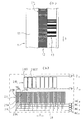
照明システムとして形成された本発明による位置測定装置の第1実施形態を図1(a)、(b)及び図2(a)、(b)に基づいて記載する。この際図1(a)は、走査光路の図式的形態、一方図1(b)及び図2(a)、(b)は、位置測定装置の走査板、測定尺並びに検出装置の平面図を示す。
【0021】
本発明による位置測定装置の第1実施形態は、測定尺1並びに測定方向xにおいて互いに相対的に移動可能な走査ユニット2を有し、その際測定方向xは、図平面に対して垂直に向けられている。測定尺1及び走査ユニット2は、互いに距離dA に配設されている。この変形において、図示の位置測定装置は、走査ユニット2と測定尺1との間のx軸線に沿うリニアー相対移動の検出のために役立ち、例えばこの位置測定装置は、工具と工作物との相対位置を高精度で検出するために、数値制御された工作機械に使用されることができる。
【0022】
測定尺1の面上には目盛板1.2として、公知の形式及び方法で形成されたインクリメンタル目盛トラックが支持体1.1上に配設されている。位相差に依存するインクリメンタル信号の発生のために測定尺1.2の傍らに、図示の実施例においては、更に参照マーク1.3が測定尺1の支持体1.1上に設けられている。参照マーク1.3によって若しくは相応した参照パルス信号の発生を介して測定運転中に公知の形式及び方法で位置測定における絶対的基準が作られる。
【0023】
目盛板1.2も参照マーク1.3も、相異なる光学的反射特性、例えば高反射部分領域及び反射しない部分領域を有する測定方向xに交番する部分領域の連続から成る。インクリメンタル目盛板1.2の目盛周期は、TPM で表され、TPM は、測定方向xにおける高反射部分領域及び反射しない部分領域の幅の総和によって特定されている。
【0024】
参照マーク1.3は、公知の形式及び方法で相異なる反射特性の部分領域の非周期的な目盛から成り、勿論例えば距離のコード化された参照マーク等のように、測定区間に沿ってそのような複数の参照マーク1.3が目盛板1.2に隣接した特定された位置に設けられることもできる。
【0025】
図示の位置測定装置の走査ユニット2は、光源2.1、コリメータ光学系2.2、走査板2.3並びに検出ユニット2.8を有する。走査板2.3には、2つの窓領域2.4、2.6が目盛構造を備え、一方他の2つの窓領域2.5、2.7は、透明であり、即ち目盛構造なしに形成されている。常に対の窓領域2.4、2.5が位相差に依存するインクリメンタル信号の発生のための位置測定装置の他の構成要素と関連して使用され、一方第2の対の窓領域2.6、2.7は、1つ又は複数の参照パルス信号の発生のために使用される。検出ユニット2.8の面上には、インクリメンタル信号の検出のための第1の検出器装置2.9が設けられており、その傍らに参照パルス信号の検出のための第2の検出装置2.10がある。
【0026】
次に図示の位置測定装置の内方のインクリメンタル信号の発生のための走査光路を説明する。参照パルス信号の発生のための光路についてはここでは詳しく説明しない。小さい射出面を備え光源2.1、例えば光線の強い赤外線−LEDがコリメータ光学系2.2から平行に向けられかつ走査板2.3の窓領域2.4において目盛構造を通る。走査板2.3の窓領域2.4における目盛構造では、本発明の場合透過目盛として形成された本発明の位置測定装置が対象とされる。投影目盛の本発明による構成については次の記載において詳しく説明する。続いて投影目盛を通って窓領域2.4に現れる光束は、この例で測定尺1の反射目盛として形成された測定尺1の面上の目盛板1.2上に現れる。目盛板1.2は、本発明による位置測定装置のこの実施形態において上記の説明の意味で検出目盛として機能する。投影目盛及び検出目盛は、更に僅かに相違する目盛周期を有し、その結果検出目盛若しくは目盛板での周期的な反射後上記説明のように、周期的な副尺縞模様が生じる。目盛板1.2若しくは検出目盛から光束が走査板2.3の透明な窓領域2.5の方向に反射される。透明な窓領域2.5を通った後、光束は、検出ユニット2.8の検出装置2.9に達する。検出装置2.9は、副尺縞模様の検出のため及び位相差に依存するインクリメンタル信号の発生のために使用される。検出装置2.9は、これに対して個々の狭く、矩形状の多数の検出要素2.9A、2.9B、2.9C、2.9Dから成り、これらの要素は測定方向xに互いに隣接して配設されている。n=4の検出要素2.9A、2.9B、2.9C、2.9Dに従って、この実施形態においては構成された検出装置の周期TPPEの内方に配設されている。周期TPPEは、この実施形態では副尺目盛の目盛周期に相応する。それぞれ副尺縞模様の走査の際に位相の等しいインクリメンタル走査信号INCA、INCB、INCC、INCDを供給する検出要素2.9A、2.9B、2.9C、2.9Dは、記載のように互いに伝導的に接続されており、即ち図示の実施例においてはそれによって符号2.9Aを備えた全ての検出要素が互いに接続している。同様に符号2.9Bを備えた検出要素が互いに接続している。そのように発生する走査信号INCA、INCB、INCC、INCDは、互いに90°の位相差を有する。走査信号INCA、INCB、INCC、INCD から公知の形式及び方法で差増幅器によって90°位相差のある2つの直流部分を含まないインクリメンタル信号が発生されかつ例えば図示しない評価装置によってさらに処理される。
【0027】
図2(b)に表す参照パルス信号の発生のための検出装置2.10は、同様に測定方向xに順次配設されている多数の個々の検出要素2.10T、2.10GTから成る。この際各第2の検出要素2.10T、2.10GTは、互いに接続され、その結果互いに接続されて公知の形式及び方法で参照パルス信号を供給する両出力信号ZT及びZGTが得られる。参照パルス信号発生のための他の詳細については、この関連において米国特許出願第19936181.9号明細書が参照される。
【0028】
次に図3(a)及び3(b)に基づいて、位置測定装置の第1実施例において図1(a)、(b)及び図2(a)、(b)中で走査板2.3の窓領域2.4に使用されるように、好適な投影目盛24の第1の好適な実施形態を説明する。そのような投影目盛2.4の使用は、本発明による位置測定装置が測定尺1と走査ユニット2との間の走査距離dAにの変動について明らかに大きな公差を有することが確保される。
【0029】
図3(a)は、この変形において透過目盛として形成された投影目盛2.4の部分の平面図であり、一方図3(b)には、図3(a)に記載された切断線による投影目盛24の断面図が表されている。この実施例の投影目盛24は、透明な支持体基体24.1、例えばガラスの上面に配設された目盛構造から成る。固有の目盛構造は、更に測定方向xに交互に配設された、周期的な振幅構造及び位相構造を有する。この際振幅構造は、クロムから成る周期的に配設された不透明なウエブ24.2によって形成されている。これに対して周期的な位相構造は、同様に周期的に配設されているウエブ24.3から成り、ウエブは、透過光に位相差のある作用を有する。位相差を有するウエブ24.3用の材料としてTiO2、SiO2又は他の透明なゾル−ゲル層が好適である。ウエブ24.3で得られる位相φは、φ=πに選択される。
【0030】
そのように形成された投影目盛24の製造のために位相構造のウエブ24.3を図3(b)に表されたウエブよりも広く選択することを有利であり、その結果ウエブ縁は振幅構造の不透過ウエブ24.2の上又は下の略中央に位置する。
【0031】
本発明による位置測定装置における投影目盛24の有利な作用にとって、投影目盛24の位相構造及び振幅構造の目盛周期若しくは周期性の選択が決定的なことである。TPASによって次に不透過ウエブ24.2の振幅構造若しくは周期性の目盛周期が表される。これに対してTPpsは、周期的位相構造の位相のずれたウエブ24.3の目盛周期を与える。本発明によれば、目盛周期TPAS、TPPSは、次の公式(1)及び(2)によって選択される。
TPAS=1/2・TPPS (方程式1)
TPAS=1/η・TPdA (方程式2)
方程式(2)におけるパラメータηは、コリメータ光学系なしの拡散照明の場合にのみη=1とは異なるように選択される発散条件づけされた拡大フアクタを表す。コリメータ光学系を有するシステムが記載された図1(a)、(b)及び図2(a)、(b)の実施例において、η=1に選択される。基本的にηは、範囲(1;+∞)に位置する。一般に拡大ファクタηは次の方程式(2′)によって与えられる。
【0032】
η=1+D2/D1 ( 2′)
この際値D2及びD1は、次に図3によって詳しく説明するように、走査光路における特定の目盛の間の距離を表す。
【0033】
方程式(2)に更に使用される値TPDAは、各検出目盛の直前の合成された縞模様の周期を具体的に表す。TPDAは、一般的な場合に次の方程式(3)及び(3′)によって得られる。
【0034】
TPdA=(TPDET×Δ)/Δ±TPDET) (方程式3)
その際
Δ=〔(D1+D2)/(D1+D2+D3)×(TPps/(n×m±1)〕
(方程式3′)
方程式(2′)、(3)、(3′)における相異なる値の説明のために、図4が参照され、図4は、関連する幾何学的パラメータを備えた位置測定装置の引き延ばされた構造を示す。パラメータは上記の議論された場合に(任意の)送り目盛ST、投影目盛PT、検出目盛DT並びに(任意の)副尺及び後続の検出要素から成る。図3に表された変形において、副尺目盛及び検出要素は、検出平面DEにおける既に述べた構成の検出装置の形の一体構成部分として形成されている。
【0035】
両公式(3)、(3′)における相異なるパラメータは、この際次に定義される。
TPDET=使用された検出目盛の目盛周期
D1:=送り目盛を備えた換算するシステムが存在する限り、送り目盛−投影目盛の距離
D2:=投影目盛−検出目盛の距離
D3:=検出目盛−検出平面の距離
TPPE=検出平面における検出装置の周期性若しくは検出平面における副尺目盛の目盛周期
n=1、2、・・:検出器配列によって供給されるべき位相のずれた信号部分の数
上記方程式は、コリメータ照明の場合も、拡散照明を備えた本発明による位置測定装置が形成される場合をも記載する。コリメータ照明の場合に、上記の説明のように送り目盛は必要なく、即ちD1は∞である。副尺なしの拡散した照明では、方程式(3)若しくは(3′)においてD3 =0及びTPDET =∞に選択される。検出目盛の機能はこの場合に直接検出器配列が担う。
【0036】
更に図3(a)及び図3(b)に表された投影目盛24によって、0次の回折及び偶数次の回折の他に±3次の回折も抑制されることが保証される。このことは、振幅構造の透過領域及び不透過領域の好適な幅の選択によって及び位相のずれた部分領域の光学的作用によって確保される。振幅構造において目盛周期TPASの内方に、bS=1/3TPASの不透過ウエブ24.2の幅bSが選択され、即ち振幅構造の透過溝領域の幅bL は、bL=2/3TPASになる。振幅構造の各第2の透過溝領域には、位相φの位相のずれた部分領域24.3が配設されている。種々の幅に対する上記の値は、スカラー計算により求められる。
【0037】
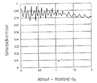
遂に上記のように、特に目盛周期24の本発明による構成に基づいて、走査距離dAの場合によっては生じる変動に対する明らかに大きな公差が与えられる。図9に比較して走査距離dAの比較的大きな領域に亘って等しい格子像コントラスト従って等しい走査信号品質が得られる。
【0038】
次に位置測定装置の第1実施例及び説明された投影目盛をベースとして本発明の具体的な実施例を説明する。
【0039】
D1→∞;D2=0.8mm;D3=3mm
TPDET=20μm;TPPS=39.024μm;TPAS=19.5212μm、
Δ=800μm;TPDA=19.512μm;TPpE=800μm
n=4;m=0
好適な投影目盛のための他の好適な実施形態は、図5(a)、(b)、図6(a)、(b)に基づいて説明する。これらの変形は原理的に説明した図3(a)、図3(b)の第1実施例を基礎としている。
【0040】
第1実施例とは異なり、次の両変形においては、そこで完全に不透過に形成された投影目盛のそのような部分領域24.2のみを示す。
【0041】
図5(a)、5(b)の第2実施例が設けられ、支持体基板44.1上に配設された部分領域は、測定方向xに対して垂直に強い偏向作用を有する回折を生じさせる横断目盛構造を備える。この目盛基体は、結局第1実施例の不透過部分領域と同様に、これらの領域に検出要素の方向の光は達しないように作用する。このために測定方向xに対して横断方向にこの部分領域44.2に相応した回折構造が設けられる。さもなければ、このために投影目盛44の変形について、同様に上記の寸法規定が通用する。周期的に配設された位相構造の部分領域44.3は、上記のように形成されている。
【0042】
第2の例に類似して、図6(a)及び(b)に相異なる正面で示された好適な投影目盛54の第3の実施例が形成されている。前記変形とは相違して、領域54.2に投影目盛の基本目盛構造に対して平行に配設された目盛構造が設けられている。この目盛基体は、同様にこの部分領域54.2からの光の著しい偏向を作用し、その結果結局光がこの部分領域54.2から検出要素上に達することが回避される。支持体基体54.1上の位相構造の部分領域54.3の形成は、上記の実施例に相応する。
【0043】
好適な投影目盛の最後に説明した両実施例において、図3(a)、(b)の第1実施例の振幅構造の不透過部分領域は、好適な目盛−基体を備える。これらは、強い偏向に基づいてそれぞれ第1の例の不透過部分領域と同様に、光がこの領域から検出要素の方向には達しないように作用する。従ってこれらの部分領域は、第1実施例の振幅構造を備えたものと等価と見做される。
【0044】
結局本発明による光学的位置測定装置の2つの他の実施変形を図1(a)、(b)及び図2(a)、(b)の第1実施形態に比して変調された走査構成を表す図7(a)、(b)及び図8に基づいて説明する。
【0045】
図7(a)には、本発明による位置測定装置の第2実施形態の基本構造が表されており、これは同様に測定尺61と測定方向xに移動可能な走査ユニット62を有する。測定尺61の側には、更に支持体61.1上に公知の形式及び方法で好適な周期的な目盛板62.1が配設されている。走査ユニット62の側には光源62.1、その上に配設されている投影目盛64を備えた走査板62.3、構造された検出器配列62.4を備えた検出ユニット62.8並びに絞り要素62.10が設けられている。
【0046】
光源62.1から射出される光束は、先ず−前方のコリメーションなしに−この領域において光学的に有効ではない走査板62.3によって測定尺61の反射する目盛板61.2上に達する。目盛板61.2は、冒頭に説明した意味で拡散する照明を有するシステムにおける送り目盛として作用し、送り目盛は反射目盛として形成されている。拡散する照明に基づいて走査ユニット62上に光源62.1と検出ユニット62.8との間の絞り要素62.10が配設されており、絞り要素は、光源62.1から射出された光線が検出器配列62.4上に達することを阻止する。目盛板61.2からその上に表される光束の反射が走査板62.3上に配設された投影目盛64の方向に行われる。投影目盛64は、更に図3(a)、(b)に説明した実施形態のように形成されており、その結果生じた格子像コントラストの要求される走査距離との独立性は、確保される。そのように発生した周期的な縞模様は、結局検出ユニット62.8の検出器配列62.4上に達する。既に冒頭に述べたように、検出目盛は、検出要素と関連して、検出器目盛が図7(b)に示すように、いわゆる検出器配列62.4によって形成されるように形成されている。検出要素及び検出器配列は、この際一体の構成として形成されている。検出器配列62.4は、測定方向xに隣接してかつ周期的に配設された多数の個々の検出要素62.4A、62.4B、62.4C、62.4Dを有する。発生した縞模様の走査の際に位相の等しい出力信号を供給する検出要素は、更に互いに接続され、その結果最終的に4つの90°位相のずれた出力信号であって、続いて公知の形式及び方法で処理可能である信号がINCA、INCB、INCC、INCDが得られる。
【0047】
第1実施例とは異なり、検出平面に本質的に微細な縞システムが現れる。その理由は、上記の説明のように、微細な縞システムから本質的に大きな副尺縞模様が発生することにある。そのような微細な縞システムの検出は、一般に検出器配列62.4の側に特定された措置が要求される、そのわけは隣接した検出要素62.4A、62.4B、62.4C、62.4Dの間の重畳配列に基づいて個々の検出要素は任意ではなく密接して配設されることができるからである。この理由から、測定方向xにおける隣接した検出要素62.4A、62.4B、62.4C、62.4Dの距離は、縞の周期の半分よりも大きく選択される。このことは、パラメータmが:m>0として選択されることを意味する。更に検出要素62.4A、62.4B、62.4C、62.4Dの幅は、各縞周期よりも小さく選択される。検出器配列62.4上に蒸着されかつ個々の検出要素62.4A、62.4B、62.4C、62.4Dの領域に開口を有する光不透過性の金属層は、検出要素62.4A、62.4B、62.4C、62.4Dの間の不所望な光入射を阻止する。
【0048】
第3の実施例は、結局図8に基づいて説明され、その際この変形は前に説明した変形とは走査光路を考慮して相違する。測定尺71及び走査ユニット72は、この例において記載の測定方向xにおいて互いに移動可能に配設されている、測定方向は図平面に対して垂直に向けられている。測定尺71は、測定方向xにおいて周期的な目盛板71.2上に配設された支持体71.1から成る。走査ユニット72の側でプレート72.0上に光源72.1と、検出器配列72.4を備えた検出ユニット72.8が設けられている。更に走査ユニット72は、その上に配設された送り目盛72.9を備えた走査板72.3を有し、その際プレート72.0の走査板72.3は、走査ユニット72に設けられている。
【0049】
光源72.1から射出される光束は、先ず−同様に再び前方のコリメータ光学系なしに−走査板72.3上の透過目盛として形成された送り目盛72.3を通り、目盛板は、この例では投影目盛として作用する。投影目盛は、この実施形態において反射目盛として形成されており、その際投影目盛若しくは目盛板71.2は、基本的に図3(a)、(b)の例で記載されたように形成されており、その結果必要な走査距離との独立性が得られる。透過目盛の場合における不透明なウエブの代わりに、振幅構造が低い反射及び又は光を強く散乱する又は光を絞る特性を有するウエブから成る。位相構造の位相のずれた作用は、公知の方法で相異なる高さの反射面によって公知の方法で発生される。選択的に位相のずれた、透明なウエブも反射鏡層上に塗布される。
【0050】
目盛板71.2若しくは投影目盛によって反射される光束は、次に検出装置として形成されて検出器配列上に到達する前に、走査板72.3の透明な領域を通る。即ち一体の構成部分における必要な検出目盛と検出器平面とは、図2(b)による実施例のように、一体的に検出配列72.4として形成されることである。
【0051】
前記第2実施変形とは異なり、距離D1及びD2が走査距離の場合によっては偏向の際でも等しくかつそれによって方程式(2′)によれば、拡大ファクタηが一定である。更に距離D3=0(近似的)であるので、個々の目盛周期は確定的にかつ走査距離とは無関係に選択されることができる。こうして有利な方法で特に大きな組立て公差が得られる。
【0052】
上記に説明した本発明による位置測定装置の他に、本発明の領域において、本発明による光学的位置測定装置が存在する。例えば半導体レーザのような、例えば拡張され、拡散して射出する光源及び送り目盛の組合せの代わりに、送り目盛なしに点状に拡散する射出光源、送り目盛なしに例えば半導体レーザが使用されるような点状、拡散状光源も、使用されることができる。この場合に、大きさD1は、点状の光源と投影目盛との間に投影目盛の半導体の他の好適なバリエーションを表す。この場合D1は、点状の光源と投影目盛との間の距離の大きさD1と表す。本発明による発明の他の好適な変形は勿論可能である。
【図面の簡単な説明】
【図1】 図1は、本発明による位置測定装置の第1実施例を示し、(a)は、その正面図、そして(b)はその部分正面図である。
【図2】 図2は、本発明による位置測定装置の第1実施例を示し、(a)は、その目盛板と参照マークを表す図、そして(b)は、検出ユニットを表す図である。
【図3】 図3は、本発明による位置測定装置用の第1の好適な投影目盛の部分図を示し、(a)はその正面図、そして(b)はその側面図である。
【図4】 図4は、本発明による位置測定装置の実施例の特定された幾何学的大きさを説明するための拡大図である。
【図5】 図5は、本発明による位置測定装置用の第2の好適な投影目盛の部分図であり、(a)は、その正面図、そして(b)はその側面図である。
【図6】 図6は、本発明による位置測定装置のための第3の好適な投影目盛の部分図であり、(a)は、その正面図、そして(b)は、その側面図である。
【図7】 図7は、本発明による位置測定装置の第2実施例を示し、(a)は、その正面図、そして(b)は、その検出器配列を示す図である。
【図8】 図8は、本発明による位置測定装置の第3実施例の正面図である。
【図9】 図9は、本発明により構成された位置測定装置における格子像コントラストの走査距離との関連を表す図である。
【図10】 図10は、技術水準によるシステムにおける格子像コントラストの走査距離との関連を表す図である。
【符号の説明】
1.2 目盛板
2 走査ユニット
2.1 光源
24 投影目盛
44 投影目盛
54 投影目盛
61.2 目盛板
62 走査ユニット
62.1 光源
71.2 目盛板
72 走査ユニット
72.1 光源
x 測定方向[0001]
BACKGROUND OF THE INVENTION
The present invention relates to an optical position measuring device suitable for determining a precise relative position of two mutually movable objects.
[0002]
[Prior art]
A known position measuring device includes a scale unit to be scanned as a scale plate and a scanning unit that is movable in the measurement direction with respect to the scale unit and includes a light source, one or more other scale structures, and a detection device. Have. The generation of position-dependent scanning signals is based on the following basic principle of the position measuring device of interest here. One or more first graduation structures produce a fine stripe pattern that is scanned in such a position measuring device by one or more second graduation structures for generating a scanning signal. In the simplest case, such a position measuring device is intended for a so-called two-grating-transmitter in which the first graduation structure is illuminated by at least one collimated light source. A light pattern is generated on the next second scale structure, and the scale period of the second scale structure coincides with the scale period of the light pattern. In the case of relative movement of both graduation structures, a periodic modulation of the light rays passing through the second graduation structure occurs. Optoelectronics located behind the second scale structure Detection element These modulated luminous fluxes are detected via. As described in the above example, the first scale structure is next referred to as a projection scale based on the functional action of the first and second scale structures. On the other hand, the second scale structure is called a detection scale.
[0003]
In order to generate a plurality of scanning signals that are out of phase, in such a position measuring device, the scale intervals of the detection graduation and the projection graduation are often selected to be slightly different from each other. In this case, a striped pattern directed from the detection scale to the scale line of the detection scale appears. The scale period of the striped pattern that appears has a scale period that is clearly larger than that of the striped pattern on the detection scale. In connection with the striped pattern that appears as such, the so-called moire fringe will be described next. Alternatively, the projection scale and the detection scale can be slightly twisted with respect to each other. The graticule lines are not aligned parallel to each other as in the previous case, but rather have a small angle specified relative to each other. Similarly, obviously a large graduation period occurs, but the fringes are oriented perpendicular to the fringes of the detection graduations. In this case, it is called a so-called moire stripe pattern. In both cases, i.e., when the vernier stripe pattern is generated and when the moire pattern is generated, the inherent scanning of the stripe pattern generated by the other scale structure is performed each time. Next, these scale structures are referred to as vernier scales for the sake of simplicity, and this designation should of course not exclude the case of moiré fringes. In this case, the vernier scale basically has the same scale cycle and scale direction as the generated vernier stripe or moire stripe.
[0004]
In addition to the vernier scale, the vernier scale can be Detection element It is also already known to be constructed as an integral component, which is used for scanning the final generated vernier or moire fringes and for generating out-of-phase scan signals. .
[0005]
On the one hand, the position measuring devices discussed so far each have one collimator optical system, but systems operating without such a collimator optical system are also known. To this end, R.D. entitled “Analysis of lattice imaging and its application to bias metrology”. Pettigrew's publication [SPIE Vol. 36, pages 325 to 332 of European Congress on Optics applied to Metrology (1977)]. In such a position measuring device, another scale structure called a feed scale is provided between the light source and the projection scale. From each transmission gap or partial area of the feed scale, a light flux that generates a periodic stripe pattern on the detection scale is generated by the projection scale. The scale interval of the feed graduation is selected so that striped patterns generated from different gaps are amplified and superimposed on the detection graduation. As such, spatially extended light sources, such as LEDs, are used in this position measuring device.
[0006]
Considered together, the position measuring device discussed above has at least one projection graduation and detection graduation. In addition, feed scales and / or vernier scales can optionally be provided, each carrying the functions discussed above. A feed scale, a projection scale, or a detection scale can be basically used for these position measuring devices as a measuring scale or a scale plate. The feed scale and the vernier scale are generally formed as an amplitude scale structure. On the other hand, the projection scale and / or the detection scale can also be formed as a phase scale structure.
[0007]
The handling at the time of changing the scanning distance is basically of great importance in a position measuring device configured as such. This is generally specified by the distance between the graduations moving relative to each other. In some cases, existing mechanical tolerances can lead to greater or lesser variations in scan distance during the measurement run. However, as little influence as possible of the output signal, which depends on the position of such variations in scanning distance, is desirable.
[0008]
In the above position measuring apparatus, there is a relatively large dependency of the signal quality detected on the detector side at each scanning distance as a premise. In FIG. 9, these problems of the combined grating image contrast of the two-grating transmitter in the detection plane with respect to the scanning distance are described for simplicity. At this time, a projection graduation formed as a phase graduation structure having a phase φ = π and a web-gap ratio of 1: 1 is used. From FIG. 9, it is clear that a strong contrast bridge is obtained in which a scan signal with low contrast can be detected during the maximum contrast. This further means that in some cases there is an obvious loss in signal modulation in the case of undesirably varying scanning distances. Based on the strong dependence of the signal quality on the respective scanning distance, high demands are made on the mechanical compensation of all the systems, for example guidance accuracy.
[0009]
From U.S. Pat. No. 5,646,730 a position measuring device with a low scanning distance-sensitivity is known. The proposed position measuring device has an illuminated transmission measurement scale, which is formed as a pure phase structure and functions according to the terminology above as a projection scale. 0th order In addition to this diffraction, even-order diffraction is also suppressed by the projection scale. A detector array for detecting interference fringes modulated depending on the phase difference is arranged in a region behind the projection graduation where ± 1st-order diffraction interferes. In this case, the detector array has a plurality of periodically arranged individually. Detection element Consists of. In the above terminology, in this case together with the detector array or a plurality of Detection element The detection scale formed together with the target. In other embodiments, it has been proposed in this publication to form the projection graduation as a complex phase structure that additionally suppresses higher order diffraction that is not even, thereby allowing the scanning signal of the scanning distance to be scanned. Somewhat greater insensitivity is affected. The intended distance insensitivity is only given conditionally in the solution proposed here. Despite the suppression of all low order diffraction, the pure phase structure is also provided with significantly higher order diffraction pairs that can interfere with each other and thus cause unwanted scanning distances. . For example, it shows that the intensity modulation that occurs immediately after the projection graduation so formed is observed.
[0010]
Furthermore, a corresponding phase graduation microstructure is necessary and can therefore only be used in systems with a large graduation period, but in such a system the distance dependence is basically less dangerous.
[0011]
It is considered disadvantageous for the position measuring device to form the scale plate as a complex phase structure. This leads to a relatively large production cost, in particular when the phase structure has to be produced in the case of a linear measurement system over the entire measurement length, for example as disclosed in FIG. In addition, only the illuminated area with a relatively small projection graduation is used for the generation of position-dependent scanning signals, thereby obtaining a higher contamination insensitivity of the system.
[0012]
[Problems to be solved by the invention]
Accordingly, the present invention provides an optical position measurement device in which there is a clearly increased tolerance in the generation of position-dependent scanning signals for variations in scanning distance. In some cases, a sufficiently constant signal modulation is required when the scales move relative to each other even with a deformed scanning distance. In particular, a scale structure to be manufactured as easily as possible should be used.
[0013]
[Means for Solving the Problems]
The object of the invention is solved by an optical position measuring device having the features of
[0014]
Advantageous embodiments of the optical position measuring device according to the invention result from the measures described in the dependent claims.
[0015]
According to the present invention, as long as the specified scale structure satisfies a specific condition, the scale structure manufactured relatively easily in the above-described position measuring device is also used for solving the above-mentioned problem. It was recognized that According to the present invention, a two-component phase structure and an amplitude structure are formed that are arranged in the measurement direction and alternately arranged in the measurement direction that satisfies the specified condition.
[0016]
Such a scale structure is already known from US Pat. No. 4,618,214. However, this publication suggests that such a scale structure can be used in special position measuring devices. Therefore, if the scale structure functions as a projection scale in the specified scanning device of the optical position measuring device in the projection scale, it is likewise understood that specific dimensional measures for the scale structure so formed are grasped. Few.
[0017]
According to the scanning function, the projection graduations can be arranged in the scanning light path at different locations, i.e. there are possible scanning arrangements in the region of the invention having the above advantages with respect to small scanning distance sensitivity at once. Arise. Of course, a linear scanning device can of course be formed according to the invention as well as a rotary deformation.
[0018]
In an advantageous embodiment of the device according to the invention, each projection graduation has at least ± in addition to even-order diffraction. Tertiary The diffraction is suppressed. Already such measures result in a significant reduction in scanning distance sensitivity without high order diffraction having a negative impact on signal quality.
[0019]
Other advantages and details of the invention are obtained from the following description of several embodiments on the basis of the drawings.
[0020]
【Example】
A first embodiment of a position measuring device according to the invention formed as an illumination system will be described on the basis of FIGS. 1 (a), (b) and FIGS. 2 (a), (b). In this case, FIG. 1A shows a schematic form of a scanning optical path, while FIGS. 1B, 2A, and 2B show a scanning plate, a measuring scale, and a plan view of a detecting device of a position measuring device. Show.
[0021]
The first embodiment of the position measuring device according to the invention comprises a
[0022]
On the surface of the
[0023]
Both the scale plate 1.2 and the reference mark 1.3 consist of a series of alternating partial areas in the measuring direction x with different optical reflection properties, for example highly reflective partial areas and non-reflective partial areas. The scale interval of the incremental scale plate 1.2 is TP M TP M Is specified by the sum of the widths of the highly reflective partial region and the non-reflective partial region in the measurement direction x.
[0024]
The reference mark 1.3 consists of non-periodic scales of partial areas with different reflection characteristics in a known manner and method, and of course along its measuring section, such as a distance-coded reference mark. A plurality of such reference marks 1.3 may be provided at specified positions adjacent to the scale plate 1.2.
[0025]
The
[0026]
Next, the scanning optical path for generating an incremental signal inside the position measuring apparatus shown in the figure will be described. The optical path for generating the reference pulse signal will not be described in detail here. A light source 2.1 with a small exit surface, e.g. a strong infrared-LED, is directed parallel from the collimator optics 2.2 and passes through the scale structure in the window area 2.4 of the scanning plate 2.3. In the scale structure in the window region 2.4 of the scanning plate 2.3, in the case of the present invention, the position measuring device of the present invention formed as a transmission scale is targeted. The configuration of the projection scale according to the present invention will be described in detail in the following description. Subsequently, the light flux that appears in the window region 2.4 through the projection scale appears on the scale plate 1.2 on the surface of the
[0027]
The detection device 2.10 for the generation of the reference pulse signal shown in FIG. Detection element 2.10T, 2.10GT. At this time, each second Detection element 2.10T and 2.10GT are connected to each other, resulting in both output signals ZT and ZGT supplying the reference pulse signal in a known manner and manner. For other details for generating a reference pulse signal, reference is made in this context to US Patent Application No. 19933161.99.
[0028]
Next, based on FIGS. 3A and 3B, in the first embodiment of the position measuring device, the
[0029]
FIG. 3 (a) is a plan view of a portion of the projection scale 2.4 formed as a transmission scale in this modification, while FIG. 3 (b) is shown by the cutting line described in FIG. 3 (a). A cross-sectional view of the
[0030]
For the production of the
[0031]
For the advantageous operation of the
TP AS = 1/2 ・ TP PS (Equation 1)
TP AS = 1 / η · TPd A (Equation 2)
The parameter η in equation (2) represents the divergent conditioned magnified factor that is selected to differ from η = 1 only in the case of diffuse illumination without collimator optics. In the example of FIGS. 1 (a), (b) and FIGS. 2 (a), (b) where a system with a collimator optical system is described, η = 1 is selected. Η is basically located in the range (1; + ∞). In general, the expansion factor η is given by the following equation (2 ′).
[0032]
η = 1 + D 2 / D 1 (2 ')
At this time, the value D 2 And D 1 Represents the distance between specific graduations in the scanning optical path, as will be explained in more detail below with reference to FIG.
[0033]
The value TP further used in equation (2) DA Specifically represents the cycle of the combined stripe pattern immediately before each detection scale. TP DA Is obtained by the following equations (3) and (3 ') in the general case:
[0034]
TPd A = (TP DET × Δ) / Δ ± TP DET (Equation 3)
that time
Δ = [(D 1 + D 2 ) / (D 1 + D 2 + D 3 ) X (TP ps / (N × m ± 1)]
(Equation 3 ')
For an explanation of the different values in equations (2 ′), (3), (3 ′), reference is made to FIG. 4, which is an extension of a position measuring device with associated geometric parameters. The structure is shown. Parameters discussed above are (optional) feed scale ST, projection scale PT, detection scale DT, and (optional) vernier and subsequent Detection element Consists of. In the deformation represented in FIG. Detection element Is formed as an integral component in the form of a detection device of the configuration already described in the detection plane DE.
[0035]
The different parameters in both formulas (3), (3 ') are then defined next.
TP DET = Scale interval of detection scale used
D 1 : = As long as there is a conversion system with a feed scale, the distance between the feed scale and the projected scale
D 2 : = Projection scale-Detection scale distance
D 3 : = Detection scale-Detection plane distance
TP PE = Periodicity of the detector on the detection plane or scale cycle of the vernier scale on the detection plane
n = 1, 2,...: number of out-of-phase signal parts to be supplied by the detector array
The above equations describe both the case of collimator illumination and the case where a position measuring device according to the invention with diffuse illumination is formed. In the case of collimator illumination, no feed graduation is required as described above, ie D 1 Is ∞. For diffuse lighting without a vernier, D in equation (3) or (3 ') 3 = 0 and TP DET = ∞ is selected. The detector scale functions directly in this case in the detector array.
[0036]
Further, by the
[0037]
Finally, as described above, particularly on the basis of the configuration according to the invention of the
[0038]
Next, a specific embodiment of the present invention will be described based on the first embodiment of the position measuring apparatus and the projection scale described.
[0039]
D 1 → ∞; D 2 = 0.8 mm; D 3 = 3mm
TP DET = 20 μm; TP PS = 39.024 μm; TP AS = 19.5212 μm,
Δ = 800 μm; TP DA = 19.512 μm; TP pE = 800μm
n = 4; m = 0
Another preferred embodiment for a preferred projection scale will be described with reference to FIGS. 5 (a), 5 (b), 6 (a), 6 (b). These modifications are based on the first embodiment shown in FIGS. 3A and 3B described in principle.
[0040]
Unlike the first embodiment, in the following two variants, only such a partial area 24.2 of the projection scale formed there completely is shown.
[0041]
5 (a) and 5 (b) is provided, and the partial region disposed on the support substrate 44.1 exhibits diffraction having a strong deflection action perpendicular to the measurement direction x. A transverse scale structure is provided. After all, the scale substrate is in these areas as in the non-transparent partial area of the first embodiment. Detection element It works so that light in the direction of is not reached. For this purpose, a diffractive structure corresponding to this partial region 44.2 is provided in a direction transverse to the measuring direction x. Otherwise, for this reason, the above-mentioned dimension definition applies to the deformation of the
[0042]
Similar to the second example, a third embodiment of the
[0043]
In both embodiments described at the end of the preferred projection scale, the impermeable partial region of the amplitude structure of the first embodiment of FIGS. 3 (a) and 3 (b) comprises a suitable scale-substrate. These are based on strong deflections, respectively, as well as the non-transparent partial area of the first example, so that light can travel from this area. Detection element It works so as not to reach the direction. Therefore, these partial areas are considered equivalent to those having the amplitude structure of the first embodiment.
[0044]
Finally, two other implementation variants of the optical position measuring device according to the invention are modulated in comparison with the first embodiment of FIGS. 1 (a), (b) and FIGS. 2 (a), (b). This will be described with reference to FIGS. 7A, 7 </ b> B, and 8.
[0045]
FIG. 7 (a) shows the basic structure of a second embodiment of the position measuring device according to the present invention, which likewise comprises a measuring
[0046]
The light beam emitted from the light source 62.1 first reaches the scale plate 61.2 reflected by the measuring
[0047]
Unlike the first embodiment, an essentially fine fringe system appears in the detection plane. The reason is that an essentially large vernier stripe pattern is generated from a fine stripe system as described above. Detection of such fine fringe systems generally requires action specified on the side of the detector array 62.4, because it is adjacent Detection element Based on the overlapping arrangement between 62.4A, 62.4B, 62.4C, 62.4D Detection element This is because they can be arranged closely, not arbitrarily. For this reason, adjacent in the measurement direction x Detection element The distances 62.4A, 62.4B, 62.4C, 62.4D are selected to be greater than half the fringe period. This means that the parameter m is selected as: m> 0. More Detection element The widths of 62.4A, 62.4B, 62.4C, and 62.4D are selected to be smaller than each fringe period. Deposited on detector array 62.4 and individual Detection element The light-impermeable metal layer having openings in the regions 62.4A, 62.4B, 62.4C, 62.4D Detection element Block unwanted light incidence between 62.4A, 62.4B, 62.4C, 62.4D.
[0048]
The third embodiment will eventually be described with reference to FIG. 8, in which case this deformation differs from the previously described deformation in view of the scanning optical path. The measuring
[0049]
The light beam emitted from the light source 72.1 first passes through the feed scale 72.3 formed as a transmission scale on the scanning plate 72.3, similarly again without the front collimator optical system. In the example, it acts as a projection scale. The projection graduation is formed as a reflection graduation in this embodiment, and the projection graduation or scale plate 71.2 is basically formed as described in the example of FIGS. 3 (a) and 3 (b). As a result, independence from the required scanning distance is obtained. Instead of an opaque web in the case of a transmission scale, it consists of a web having a low-amplitude reflection and / or properties that strongly scatter or squeeze light. The phase-shifted action of the phase structure is generated in a known manner by reflecting surfaces of different heights in a known manner. A transparent web, optionally out of phase, is also applied on the reflector layer.
[0050]
The light beam reflected by the scale plate 71.2 or the projection scale passes through the transparent area of the scanning plate 72.3 before it is then formed as a detector and reaches the detector array. That is, the necessary detection scale and detector plane in the integral component are integrally formed as a detection array 72.4 as in the embodiment of FIG.
[0051]
Unlike the second embodiment variant, the distance D 1 And D 2 Is equal even in deflection, depending on the scanning distance, and according to equation (2 '), the enlargement factor η is constant. Further distance D 3 Since = 0 (approximate), the individual graduation periods can be selected deterministically and independently of the scanning distance. A particularly large assembly tolerance is thus obtained in an advantageous manner.
[0052]
In addition to the position measuring device according to the invention described above, in the region of the invention there is an optical position measuring device according to the invention. For example, instead of a combination of a light source that is expanded and diffused and emitted, such as a semiconductor laser, and a feed graduation, an emission light source that diffuses in a dotted manner without a feed graduation, for example, a semiconductor laser is used without a feed graduation. Various spot-like and diffuse light sources can also be used. In this case, the size D 1 Represents another suitable variation of the semiconductor of the projection scale between the point-like light source and the projection scale. In this case D 1 Is the distance D between the point light source and the projection scale D 1 It expresses. Other suitable variants of the invention according to the invention are of course possible.
[Brief description of the drawings]
FIG. 1 shows a first embodiment of a position measuring apparatus according to the present invention, in which (a) is a front view thereof and (b) is a partial front view thereof.
2A and 2B show a first embodiment of a position measuring apparatus according to the present invention, in which FIG. 2A is a diagram showing a scale plate and a reference mark, and FIG. 2B is a diagram showing a detection unit; .
FIG. 3 shows a partial view of a first preferred projection scale for a position measuring device according to the invention, in which (a) is a front view thereof and (b) is a side view thereof.
FIG. 4 is an enlarged view for explaining a specified geometric size of an embodiment of the position measuring device according to the present invention.
FIG. 5 is a partial view of a second preferred projection scale for a position measuring device according to the present invention, where (a) is a front view thereof and (b) is a side view thereof.
FIG. 6 is a partial view of a third preferred projection scale for a position measuring device according to the present invention, wherein (a) is a front view thereof and (b) is a side view thereof. .
7A and 7B show a second embodiment of the position measuring apparatus according to the present invention, in which FIG. 7A is a front view thereof and FIG. 7B is a diagram showing a detector arrangement thereof.
FIG. 8 is a front view of a third embodiment of the position measuring apparatus according to the present invention.
FIG. 9 is a diagram showing the relationship between the lattice image contrast and the scanning distance in the position measuring apparatus configured according to the present invention.
FIG. 10 is a diagram showing the relationship between the scanning distance of the lattice image contrast in the system according to the state of the art.
[Explanation of symbols]
1.2 Scale plate
2 Scanning unit
2.1 Light source
24 Projection scale
44 Projection scale
54 Projection scale
61.2 Scale plate
62 Scanning unit
62.1 Light source
71.2 Scale plate
72 Scanning unit
72.1 Light source
x Measuring direction
Claims (10)
その際位置測定装置は、光源(2.1;62.1;72.1)、投影目盛(24;44;54)、検出目盛、および複数の検出要素を有するか、
光源(2.1;62.1;72.1)、送り目盛、投影目盛(24;44;54)、検出目盛、副尺目盛および複数の検出要素を有するか、
光源(2.1;62.1;72.1)、送り目盛、投影目盛(24;44;54)、検出目盛、および複数の検出要素を有するか、
光源(2.1;62.1;72.1)、投影目盛(24;44;54)、検出目盛、副尺目盛、および複数の検出要素を有するかし、
そして光源(2.1;62.1;72.1)の光は、投影目盛(24;44;54)との相互作用において縞模様を検出目盛上に投影し、その結果検出要素を介して変位に依存する出力信号が検出可能であり、その際投影目盛(24;44;54)は、偶数次の回折及び0次の回折の他に、(2n+1)次の回折(ここにn=1、2、3、・・・)の少なくとも一部分が、抑制され、それによって実質的に±1次の回折のみが出力信号の発生に寄与し、そして投影目盛(24;44;54)が、測定方向(x)に交互に配設された周期的な振幅構造及び位相構造から成る、前記光学的位置測定装置。An optical position measuring device comprising a scale plate (1.2; 61.2; 71.2) and a scanning unit (2; 62; 72) movable relative to this in at least a measuring direction (x) ,
At that time position measuring device includes a light source (2.1; 62.1; 72.1), throw shadows scale (24; 44; 54), or with a detection scale, and a plurality of detection elements,
A light source (2.1; 62.1; 72.1), a feed scale, a projection scale (24; 44; 54), a detection scale, a vernier scale and a plurality of detection elements;
A light source (2.1; 62.1; 72.1), a feed scale, a projection scale (24; 44; 54), a detection scale, and a plurality of detection elements;
A light source (2.1; 62.1; 72.1), a projection scale (24; 44; 54), a detection scale, a vernier scale, and a plurality of detection elements;
The light from the light source (2.1; 62.1; 72.1) then projects a striped pattern onto the detection scale in interaction with the projection scale (24; 44; 54), with the result that via the detection element. An output signal dependent on the displacement can be detected, in which the projection scale (24; 44; 54) has (2n + 1) -order diffraction (where n = 1) in addition to even-order diffraction and zero-order diffraction. 2, 3,...) Are suppressed, whereby substantially only the ± 1st order diffraction contributes to the generation of the output signal, and the projection scale (24; 44; 54) is measured. Said optical position measuring device comprising periodic amplitude structures and phase structures arranged alternately in direction (x).
TPAS=1/2・TPPS
及び
TPAS=1/η・TPDA
であり、その際
ηは、方程式
η=1+D2/D1
によって得られ、
TPDAは、各検出目盛の直前の合成された縞模様の周期を表わし、上記周期は、
TPDA=TPDET・Δ/(Δ±TPDET)によって得られ、
その際
Δ=〔(D2+D1)/(D1+D2+D3)〕・(TPPE/(n・m±1)〕であり、その際
TPDET:=使用された検出目盛の目盛周期
D1:=送り目盛を備えた発散するシステムが存在する場合の送り目盛と投影目盛との距離
D2:=投影目盛と検出目盛との距離
D3:=検出目盛と検出平面との距離
TPPE:=検出平面における検出器配列の周期性又は検出平面における副尺の目盛周期
n=1、2、・・・:検出器配列から供給されるべき位相のずれた信号部分の数m=0、1、2、3、・・・・である、請求項1に記載の光学的位置測定装置 Amplitude structure and the phase structure respectively have periodicity TP AS, the TP PS, i.e. TP AS = 1/2 · TP PS
And TP AS = 1 / η · TP DA
Where η is the equation η = 1 + D 2 / D 1
Obtained by
TP DA represents the cycle of the combined stripe pattern immediately before each detection scale, and the cycle is
TP DA = TP DET · Δ / (Δ ± TP DET ),
In this case, Δ = [(D 2 + D 1 ) / (D 1 + D 2 + D 3 )] · (TP PE / (n · m ± 1)], where TP DET : = scale of detection scale used Period D 1 : = Distance between feed graduation and projection graduation D 2 when there is a diverging system with feed graduation D 2 : = Distance between projection graduation and detection graduation D 3 : = Distance between detection graduation and detection plane TP PE : = periodicity of detector array in detection plane or vernier scale period n = 1,2,... In detection plane: number of out-of-phase signal parts to be supplied from detector array m = The optical position measuring device according to claim 1, which is 0, 1, 2, 3,.
b)投影目盛(24)の振幅構造が、TPAS=1/2・TPPSで周期的に配設された振幅構造部分領域から成り、その際そこに入射する光に対して振幅構造部分領域が不透過に形成されておりかつ測定方向において略1/3・TPASの幅を有する、請求項2又は3に記載の光学的位置測定装置。 a ) The phase structure of the projection graduation (24) is composed of phase structure partial areas periodically arranged with a scale period TP PS , and the phase structure partial area has a width of 1/2 · TP PS and is out of phase. With action and phase φ = π,
b) The amplitude structure of the projection graduation (24) is composed of amplitude structure partial areas periodically arranged at TP AS = 1/2 · TP PS , in which case the amplitude structure partial area with respect to the light incident thereon The optical position measuring device according to claim 2, wherein the optical position measuring device is formed to be opaque and has a width of approximately 1/3 · TP AS in the measurement direction.
Applications Claiming Priority (2)
| Application Number | Priority Date | Filing Date | Title |
|---|---|---|---|
| DE19941318A DE19941318A1 (en) | 1999-08-31 | 1999-08-31 | Optical position measuring device |
| DE19941318:5 | 1999-08-31 |
Publications (3)
| Publication Number | Publication Date |
|---|---|
| JP2001082984A JP2001082984A (en) | 2001-03-30 |
| JP2001082984A5 JP2001082984A5 (en) | 2007-06-14 |
| JP4503799B2 true JP4503799B2 (en) | 2010-07-14 |
Family
ID=7920223
Family Applications (1)
| Application Number | Title | Priority Date | Filing Date |
|---|---|---|---|
| JP2000261121A Expired - Fee Related JP4503799B2 (en) | 1999-08-31 | 2000-08-30 | Optical position measuring device |
Country Status (6)
| Country | Link |
|---|---|
| US (1) | US6541761B1 (en) |
| EP (1) | EP1081457B1 (en) |
| JP (1) | JP4503799B2 (en) |
| AT (1) | ATE398764T1 (en) |
| DE (2) | DE19941318A1 (en) |
| ES (1) | ES2307478T3 (en) |
Families Citing this family (28)
| Publication number | Priority date | Publication date | Assignee | Title |
|---|---|---|---|---|
| DE29916394U1 (en) * | 1999-09-17 | 2001-02-15 | Heidenhain Gmbh Dr Johannes | Optical position measuring device |
| DE19956912A1 (en) | 1999-11-26 | 2001-08-09 | Heidenhain Gmbh Dr Johannes | Angle measuring system and angle measuring method for non-contact angle measurement |
| DE19962278A1 (en) * | 1999-12-23 | 2001-08-02 | Heidenhain Gmbh Dr Johannes | Position measuring device |
| DE10130938A1 (en) * | 2001-06-27 | 2003-01-23 | Heidenhain Gmbh Dr Johannes | Position measuring device and method for operating a position measuring device |
| US7002137B2 (en) * | 2001-08-30 | 2006-02-21 | Gsi Lumonics Corporation | Reference point talbot encoder |
| GB0200575D0 (en) * | 2002-01-11 | 2002-02-27 | Rls Merilna Tehnika D O O | Encoder with reference marks |
| DE10201496A1 (en) * | 2002-01-17 | 2003-07-31 | Heidenhain Gmbh Dr Johannes | Scale and position measuring device for absolute position determination |
| US7184149B2 (en) * | 2003-06-18 | 2007-02-27 | Dimensional Photonics International, Inc. | Methods and apparatus for reducing error in interferometric imaging measurements |
| EP1519158B1 (en) | 2003-09-23 | 2010-08-11 | Dr. Johannes Heidenhain GmbH | Position measuring device |
| DE102004035172A1 (en) * | 2004-07-16 | 2006-02-09 | Dr. Johannes Heidenhain Gmbh | Position measuring device |
| DE102004053082A1 (en) * | 2004-11-03 | 2006-05-04 | Dr. Johannes Heidenhain Gmbh | Position measuring system |
| DE102005006247A1 (en) * | 2005-02-11 | 2006-08-17 | Dr. Johannes Heidenhain Gmbh | Position measuring device |
| DE102005009043A1 (en) | 2005-02-22 | 2006-08-31 | Dr. Johannes Heidenhain Gmbh | Scanning unit for a position measuring device |
| DE102006041357A1 (en) * | 2005-11-09 | 2007-05-10 | Dr. Johannes Heidenhain Gmbh | Position measuring device and method for operating a position-measuring device |
| ES2311354B1 (en) * | 2006-06-08 | 2009-11-30 | Fagor, S. Coop. | OPTOELECTRONIC MEASUREMENT DEVICE. |
| WO2008146409A1 (en) | 2007-06-01 | 2008-12-04 | Mitutoyo Corporation | Reflective encoder, scale thereof, and method for manufacturing scale |
| KR101025627B1 (en) * | 2007-08-06 | 2011-03-30 | 광주과학기술원 | Remote Controller Mouse |
| DE102008013164A1 (en) | 2008-03-07 | 2009-09-10 | Dr. Johannes Heidenhain Gmbh | Material measure for optical position measuring unit, which operates with light of central wavelength, comprises substrate with two areas, which code position information, which is selected with light of wavelength |
| TW201218047A (en) * | 2010-10-26 | 2012-05-01 | Xiroku Accupoint Technology Inc | Object sensing device |
| DE102011076055A1 (en) * | 2011-05-18 | 2012-11-22 | Dr. Johannes Heidenhain Gmbh | Optical position measuring device |
| CN102508578B (en) * | 2011-10-09 | 2015-07-22 | 清华大学深圳研究生院 | Projection positioning device and method as well as interaction system and method |
| EP2722650A1 (en) * | 2012-10-18 | 2014-04-23 | Lambda-X | Angular position sensing |
| WO2015049173A1 (en) * | 2013-10-01 | 2015-04-09 | Renishaw Plc | Reference mark detector arrangement |
| DE102014215633A1 (en) * | 2013-11-28 | 2015-05-28 | Dr. Johannes Heidenhain Gmbh | Position measuring device |
| DE102014212268A1 (en) | 2014-06-26 | 2016-01-14 | Dr. Johannes Heidenhain Gmbh | Position measuring device |
| EP3255384B1 (en) * | 2016-06-07 | 2018-11-28 | Dr. Johannes Heidenhain GmbH | Scale and a position measuring device |
| JP2020122659A (en) * | 2019-01-29 | 2020-08-13 | 日本電産株式会社 | Position detecting device, motor system and position detection method |
| DE102020208423A1 (en) | 2020-07-06 | 2022-01-13 | Dr. Johannes Heidenhain Gesellschaft Mit Beschränkter Haftung | Optical position measuring device |
Citations (3)
| Publication number | Priority date | Publication date | Assignee | Title |
|---|---|---|---|---|
| JPH07506669A (en) * | 1992-05-05 | 1995-07-20 | ビーイーアイ・エレクトロニクス・インク | Device that detects relative movement |
| JPH08271218A (en) * | 1995-03-25 | 1996-10-18 | Dr Johannes Heidenhain Gmbh | Photoelectric-position measuring device |
| JPH10501334A (en) * | 1994-05-27 | 1998-02-03 | マイクロイー・インク | Relative movement detection device |
Family Cites Families (6)
| Publication number | Priority date | Publication date | Assignee | Title |
|---|---|---|---|---|
| DE3412128C1 (en) | 1984-03-31 | 1985-05-09 | Dr. Johannes Heidenhain Gmbh, 8225 Traunreut | Position measuring device |
| US4618214A (en) | 1984-10-26 | 1986-10-21 | Itek Corporation | Method of fabricating a controlled harmonic binary grating |
| DE3616144A1 (en) | 1986-05-14 | 1987-11-19 | Heidenhain Gmbh Dr Johannes | PHOTOELECTRICAL MEASURING DEVICE |
| DE59306689D1 (en) | 1993-08-07 | 1997-07-10 | Heidenhain Gmbh Dr Johannes | Device for generating harmonic-free periodic signals |
| GB9522491D0 (en) * | 1995-11-02 | 1996-01-03 | Renishaw Plc | Opto-electronic rotary encoder |
| JP3209914B2 (en) * | 1996-03-19 | 2001-09-17 | オークマ株式会社 | Optical encoder |
-
1999
- 1999-08-31 DE DE19941318A patent/DE19941318A1/en not_active Withdrawn
-
2000
- 2000-07-25 DE DE50015209T patent/DE50015209D1/en not_active Expired - Lifetime
- 2000-07-25 EP EP00115881A patent/EP1081457B1/en not_active Expired - Lifetime
- 2000-07-25 ES ES00115881T patent/ES2307478T3/en not_active Expired - Lifetime
- 2000-07-25 AT AT00115881T patent/ATE398764T1/en not_active IP Right Cessation
- 2000-08-30 JP JP2000261121A patent/JP4503799B2/en not_active Expired - Fee Related
- 2000-08-30 US US09/652,220 patent/US6541761B1/en not_active Expired - Lifetime
Patent Citations (3)
| Publication number | Priority date | Publication date | Assignee | Title |
|---|---|---|---|---|
| JPH07506669A (en) * | 1992-05-05 | 1995-07-20 | ビーイーアイ・エレクトロニクス・インク | Device that detects relative movement |
| JPH10501334A (en) * | 1994-05-27 | 1998-02-03 | マイクロイー・インク | Relative movement detection device |
| JPH08271218A (en) * | 1995-03-25 | 1996-10-18 | Dr Johannes Heidenhain Gmbh | Photoelectric-position measuring device |
Also Published As
| Publication number | Publication date |
|---|---|
| EP1081457A3 (en) | 2001-11-21 |
| ES2307478T3 (en) | 2008-12-01 |
| DE50015209D1 (en) | 2008-07-31 |
| EP1081457B1 (en) | 2008-06-18 |
| DE19941318A1 (en) | 2001-03-15 |
| ATE398764T1 (en) | 2008-07-15 |
| JP2001082984A (en) | 2001-03-30 |
| EP1081457A2 (en) | 2001-03-07 |
| US6541761B1 (en) | 2003-04-01 |
Similar Documents
| Publication | Publication Date | Title |
|---|---|---|
| JP4503799B2 (en) | Optical position measuring device | |
| US7348546B2 (en) | Position measuring system with a scanning unit having a reference pulse signal detection unit | |
| JP5717633B2 (en) | Optical position measuring device | |
| JP5100266B2 (en) | Encoder | |
| JP4503822B2 (en) | Position measuring device | |
| US7858922B2 (en) | Position-measuring device | |
| JP4856844B2 (en) | Interferometric position measuring device | |
| JP5147367B2 (en) | Encoder | |
| JP4266834B2 (en) | Optical encoder | |
| JPH11142114A (en) | Scanning unit for optical position measuring apparatus | |
| JP2001208566A (en) | Measuring apparatus | |
| US6472658B2 (en) | Photoelectric position measuring system that optimizes modulation of a scanning device and the intensity of a reference mark signal | |
| JP2818800B2 (en) | Device for generating position-dependent signals | |
| JP4303804B2 (en) | Optical position measuring device | |
| JP4936980B2 (en) | Optical encoder | |
| US6552810B1 (en) | Optical measuring system | |
| JP2888482B2 (en) | Device for filtering harmonic signal components | |
| JP4337415B2 (en) | Encoder | |
| JP6293700B2 (en) | Encoder | |
| JP2015105953A (en) | Encoder | |
| JPH06174424A (en) | Length measuring and angle measuring device | |
| US20230136119A1 (en) | Optical position measuring device and method for operating an optical position measuring device | |
| JP3544576B2 (en) | Optical encoder | |
| TWI394934B (en) | Photoelectric encoder | |
| JP3013467B2 (en) | Laser interference encoder |
Legal Events
| Date | Code | Title | Description |
|---|---|---|---|
| A521 | Request for written amendment filed |
Free format text: JAPANESE INTERMEDIATE CODE: A523 Effective date: 20070424 |
|
| A621 | Written request for application examination |
Free format text: JAPANESE INTERMEDIATE CODE: A621 Effective date: 20070424 |
|
| A131 | Notification of reasons for refusal |
Free format text: JAPANESE INTERMEDIATE CODE: A131 Effective date: 20091027 |
|
| A521 | Request for written amendment filed |
Free format text: JAPANESE INTERMEDIATE CODE: A523 Effective date: 20091201 |
|
| TRDD | Decision of grant or rejection written | ||
| A01 | Written decision to grant a patent or to grant a registration (utility model) |
Free format text: JAPANESE INTERMEDIATE CODE: A01 Effective date: 20100323 |
|
| A01 | Written decision to grant a patent or to grant a registration (utility model) |
Free format text: JAPANESE INTERMEDIATE CODE: A01 |
|
| A61 | First payment of annual fees (during grant procedure) |
Free format text: JAPANESE INTERMEDIATE CODE: A61 Effective date: 20100422 |
|
| R150 | Certificate of patent or registration of utility model |
Free format text: JAPANESE INTERMEDIATE CODE: R150 Ref document number: 4503799 Country of ref document: JP Free format text: JAPANESE INTERMEDIATE CODE: R150 |
|
| FPAY | Renewal fee payment (event date is renewal date of database) |
Free format text: PAYMENT UNTIL: 20130430 Year of fee payment: 3 |
|
| FPAY | Renewal fee payment (event date is renewal date of database) |
Free format text: PAYMENT UNTIL: 20140430 Year of fee payment: 4 |
|
| R250 | Receipt of annual fees |
Free format text: JAPANESE INTERMEDIATE CODE: R250 |
|
| R250 | Receipt of annual fees |
Free format text: JAPANESE INTERMEDIATE CODE: R250 |
|
| R250 | Receipt of annual fees |
Free format text: JAPANESE INTERMEDIATE CODE: R250 |
|
| R250 | Receipt of annual fees |
Free format text: JAPANESE INTERMEDIATE CODE: R250 |
|
| R250 | Receipt of annual fees |
Free format text: JAPANESE INTERMEDIATE CODE: R250 |
|
| R250 | Receipt of annual fees |
Free format text: JAPANESE INTERMEDIATE CODE: R250 |
|
| R250 | Receipt of annual fees |
Free format text: JAPANESE INTERMEDIATE CODE: R250 |
|
| LAPS | Cancellation because of no payment of annual fees |