JP4498860B2 - Banknote handling equipment - Google Patents

Banknote handling equipment Download PDF

Info

Publication number
JP4498860B2
JP4498860B2 JP2004246306A JP2004246306A JP4498860B2 JP 4498860 B2 JP4498860 B2 JP 4498860B2 JP 2004246306 A JP2004246306 A JP 2004246306A JP 2004246306 A JP2004246306 A JP 2004246306A JP 4498860 B2 JP4498860 B2 JP 4498860B2
Authority
JP
Japan
Prior art keywords
banknote
withdrawal
emergency
safe
banknotes
Prior art date
Legal status (The legal status is an assumption and is not a legal conclusion. Google has not performed a legal analysis and makes no representation as to the accuracy of the status listed.)
Expired - Fee Related
Application number
JP2004246306A
Other languages
Japanese (ja)
Other versions
JP2006065539A (en
Inventor
利典 横井
利一 加藤
敦子 魚住
Current Assignee (The listed assignees may be inaccurate. Google has not performed a legal analysis and makes no representation or warranty as to the accuracy of the list.)
Hitachi Omron Terminal Solutions Corp
Original Assignee
Hitachi Omron Terminal Solutions Corp
Priority date (The priority date is an assumption and is not a legal conclusion. Google has not performed a legal analysis and makes no representation as to the accuracy of the date listed.)
Filing date
Publication date
Application filed by Hitachi Omron Terminal Solutions Corp filed Critical Hitachi Omron Terminal Solutions Corp
Priority to JP2004246306A priority Critical patent/JP4498860B2/en
Publication of JP2006065539A publication Critical patent/JP2006065539A/en
Application granted granted Critical
Publication of JP4498860B2 publication Critical patent/JP4498860B2/en
Expired - Fee Related legal-status Critical Current
Anticipated expiration legal-status Critical

Links

Images

Description

本発明は、紙幣を自動で取り扱い可能な紙幣取扱装置に関する。   The present invention relates to a banknote handling apparatus capable of automatically handling banknotes.

紙幣取扱装置は、例えば現金自動取引装置(ATM)に搭載されている。紙幣取扱装置は、紙幣を収納する金庫と、金庫から出金口まで紙幣を搬送可能な搬送路を備えており、利用者の要求に応えて、自動的に紙幣を出金口に放出することが可能である。   The banknote handling apparatus is mounted on, for example, an automatic teller machine (ATM). The banknote handling device has a safe for storing banknotes and a transport path that can transport banknotes from the safe to the withdrawal port, and automatically ejects banknotes to the withdrawal port in response to a user's request. Is possible.

特開平5−81507号公報JP-A-5-81507 特開平6−96327号公報JP-A-6-96327

しかしながら、従来の紙幣取扱装置では、例えば搬送路において紙幣が詰まるといった緊急の事態が起こった場合、紙幣を出金口に搬出することができず、出金が不可能になるという問題があった。   However, in the conventional banknote handling apparatus, for example, when an emergency situation such as banknotes being jammed in the transport path occurs, there is a problem that the banknotes cannot be carried out to the withdrawal port and the withdrawal becomes impossible. .

本発明は、上記した問題点を解決するためになされたものであり、緊急の事態が発生した場合であっても出金を可能とする紙幣取扱装置を提供することを目的とする。   The present invention has been made to solve the above-described problems, and an object of the present invention is to provide a banknote handling apparatus that enables withdrawal even when an emergency situation occurs.

上記課題の少なくとも一部を解決するため、本発明による紙幣取扱装置は、紙幣を収納する通常時用金庫と、緊急時用に紙幣を収納する緊急時用金庫と、 前記通常時用金庫から出金する通常時出金取引が可能であるか否かを検出する検出部と、前記通常時出金取引が可能であると検出された場合、出金指示に応じて、前記通常時用金庫に収納された紙幣を第一の出金口から出金する通常時出金部と、前記通常時出金取引が不可能であると検出された場合、出金指示に応じて、前記緊急時用金庫に収納された紙幣を前記第一の出金口とは別口の第二の出金口から出金する緊急時出金部と、前記通常時用金庫から前記第一の出金口へ紙幣を搬送する第一の搬送路と、前記第一の搬送路とは別の搬送路であって、前記緊急時用金庫から前記第二の出金口へ紙幣を搬送する第二の搬送路と、前記通常時用金庫と前記緊急時用金庫とを接続し、前記通常時用金庫と前記緊急時用金庫との間において紙幣を搬送する接続搬送路とを備えることを特徴とする。
In order to solve at least a part of the above problems, a banknote handling apparatus according to the present invention includes a normal safe for storing banknotes, an emergency safe for storing banknotes for emergencies, and a safe from the normal safe. a detection unit for detecting whether or not it is possible to normal dispensing transaction to gold, wherein when it is detected that it is possible to normal dispensing transaction, in accordance with the withdrawal instruction, the normal safe for time When it is detected that the stored banknotes are withdrawn from the first withdrawal port and the normal withdrawal transaction is impossible, the emergency use is made according to the withdrawal instruction. An emergency withdrawal unit for dispensing banknotes stored in a safe from a second withdrawal port different from the first withdrawal port, and from the normal safe to the first withdrawal port A first transport path for transporting banknotes and a transport path different from the first transport path, wherein the second exit from the emergency safe. A second transport path for transporting banknotes to a cash outlet, a connection for transporting banknotes between the normal safe and the emergency safe, connecting the normal safe and the emergency safe And a conveyance path .

本発明によれば、緊急時用金庫を別個に備えることにより、通常時用金庫から出金不可能である場合も出金することができる。しかも、緊急時用金庫への紙幣の補充や回収を容易に行なうことができるとともに、緊急時に第一の出金口から出金する場合に比べ、緊急時の出金をより確実に行なうことができる。
According to the present invention, by providing the emergency safe separately, it is possible to withdraw even when the withdrawal from the normal safe is impossible. Moreover, it is possible to easily replenish and collect banknotes in the emergency safe, and more reliably perform emergency withdrawals compared to withdrawing from the first withdrawal port in an emergency. it can.

前記接続搬送路の一部であって前記第一の搬送路の一部としても使用される搬送路に、紙幣を判別する紙幣判別部を有するものとしても良い。
It is good also as what has a banknote discrimination | determination part which discriminate | determines a banknote in the conveyance path which is a part of said connection conveyance path, and is used also as a part of said 1st conveyance path.

これによれば、搬送路の全長を短くすることができるとともに、搬送される紙幣を判別することができる
According to this, while being able to shorten the full length of a conveyance path, the banknote conveyed can be discriminate | determined .

なお本発明は種々の形態で実現可能であり、例えば、紙幣取扱装置を制御する方法、紙幣取扱装置の機能を実現させるためのコンピュータプログラム、そのプログラムを記録した記録媒体等の形態で実現可能である。   The present invention can be realized in various forms, such as a method for controlling a bill handling apparatus, a computer program for realizing the function of the bill handling apparatus, and a recording medium on which the program is recorded. is there.

本発明をコンピュータプログラムまたはそのプログラムを記録した記録媒体等として構成する場合には、ネットワーク機器の動作を制御するプログラム全体として構成するものとしてもよいし、本発明の機能を果たす部分のみを構成するものとしてもよい。また、記録媒体としては、フレキシブルディスクやCD−ROM、DVD−ROM、光磁気ディスク、ICカード、ROMカートリッジ、パンチカード、バーコードなどの符号が印刷された印刷物、コンピュータの内部記憶装置(RAMやROMなどのメモリ)および外部記憶装置などコンピュータが読み取り可能な種々の媒体を利用できる。   When the present invention is configured as a computer program or a recording medium on which the program is recorded, the entire program for controlling the operation of the network device may be configured, or only the portion that performs the function of the present invention is configured. It may be a thing. The recording medium includes a flexible disk, a CD-ROM, a DVD-ROM, a magneto-optical disk, an IC card, a ROM cartridge, a punch card, a printed matter on which a code such as a barcode is printed, a computer internal storage device (RAM or Various types of computer-readable media such as a memory such as a ROM and an external storage device can be used.

図1は、本発明の一実施例における現金自動取引装置100を示す説明図である。現金自動取引装置100は、下側内部に、紙幣取扱装置10を実装している。紙幣取扱装置10は、紙幣入出金スロット20aを備えており、利用者は、紙幣入出金スロット20aを介して紙幣取扱装置10に対し紙幣の出し入れを行なう。紙幣取扱装置10は、紙幣取扱装置10内の搬送路内で紙幣が詰まる等の緊急事態が発生した場合に使用する緊急時専用出金庫70を備えている。緊急時専用出金庫70は、緊急時用出金口71を備えており、緊急時には緊急時用出金口71から紙幣が排出される。紙幣取扱装置10の構造の詳細については後述する。   FIG. 1 is an explanatory diagram showing an automatic teller machine 100 according to an embodiment of the present invention. The automatic teller machine 100 has a bill handling device 10 mounted on the lower inside. The banknote handling apparatus 10 includes a banknote deposit / withdrawal slot 20a, and a user inserts / withdraws banknotes into / from the banknote handling apparatus 10 via the banknote deposit / withdrawal slot 20a. The banknote handling apparatus 10 includes an emergency emergency safe 70 that is used when an emergency such as a banknote jamming occurs in a conveyance path in the banknote handling apparatus 10. The emergency emergency deposit box 70 includes an emergency withdrawal port 71, and banknotes are discharged from the emergency withdrawal port 71 in an emergency. Details of the structure of the bill handling apparatus 10 will be described later.

現金自動取引装置100は、利用者のカードを処理し、取引明細票を印字して排出するカード・明細票処理機構102を備えている。カード・明細書処理機構102は、上部正面板101aに設けられたカードスロット102a及び取引明細書発行部102bと連通している。更に、現金自動取引装置100は、取引の内容を入力及び表示するための顧客操作部105a,105b(以下、まとめて顧客操作部105と呼ぶ)を備えている。   The automatic teller machine 100 includes a card / detail slip processing mechanism 102 that processes a user's card and prints out a transaction slip. The card / detail processing mechanism 102 communicates with a card slot 102a provided on the upper front plate 101a and a transaction statement issuing unit 102b. Furthermore, the automatic teller machine 100 includes customer operation units 105a and 105b (hereinafter collectively referred to as a customer operation unit 105) for inputting and displaying the contents of transactions.

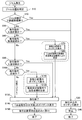
図2は、紙幣取扱装置10の構成を示す説明図である。また、図3は、図2の紙幣取扱装置10の構成を模式的に示した説明図である。紙幣取扱装置10は、図2に示すように、上部搬送機構10aと、下部紙幣機構10bと、緊急時専用出金庫70から構成される。上部搬送機構10aは、入出金口20と、紙幣判別部30と、一時保管庫40と、上部紙幣搬送路50とを備える。下部紙幣機構10bは、リサイクル庫80a,80b,80cと、リジェクト庫60と、各収納庫の上面に配される下部紙幣搬送路90とを備える。緊急時専用出金庫70は、緊急時紙幣保管部72と、緊急時用出金口71と、緊急時紙幣保管部72から緊急時用出金口71までの図中太線の点線で示される緊急時紙幣搬送路73と、切替ゲート705からポイントP2までの図中太線の一点鎖線で示される補充・回収用紙幣搬送路74を備える。   FIG. 2 is an explanatory diagram showing the configuration of the banknote handling apparatus 10. Moreover, FIG. 3 is explanatory drawing which showed typically the structure of the banknote handling apparatus 10 of FIG. As shown in FIG. 2, the banknote handling apparatus 10 includes an upper transport mechanism 10a, a lower banknote mechanism 10b, and an emergency emergency safe 70. The upper transport mechanism 10a includes a deposit / withdrawal port 20, a banknote discriminating unit 30, a temporary storage 40, and an upper banknote transport path 50. The lower bill mechanism 10b includes recycle stores 80a, 80b, 80c, a reject store 60, and a lower bill transport path 90 disposed on the upper surface of each store. The emergency bank deposit box 70 includes an emergency banknote storage unit 72, an emergency withdrawal port 71, and an emergency indicated by a thick dotted line in the figure from the emergency banknote storage unit 72 to the emergency withdrawal port 71. And a banknote transport path 74 for replenishment / collection indicated by a one-dot chain line in the drawing from the switching gate 705 to the point P2 in the drawing.

入出金口20は、利用者が紙幣PMの投入・取り出しを行うための凹部である。紙幣判別部30は、経路501bで示す箇所に存在する紙幣PMの判別をする。判別内容については後述する。一時保管庫40は、入金した紙幣PMを取引成立までの間一旦収納する。   The deposit / withdrawal port 20 is a recess for the user to insert / remove the banknote PM. The banknote discrimination | determination part 30 discriminate | determines the banknote PM which exists in the location shown by the path | route 501b. The details of the determination will be described later. The temporary storage 40 temporarily stores the deposited banknote PM until the transaction is established.

リサイクル庫80a,80b,80cは、入金取引が成立した紙幣PMを収納し、また、出金取引の際には紙幣PMを出金する。リサイクル庫80a〜80cは、本発明の通常時用金庫に相当する。リジェクト庫60は、リジェクト部60aと運用リジェクト部60bとを有している。リジェクト部60aに収納されるのは、現金自動取引装置100にとって「外のリジェクト紙幣」である。「外のリジェクト紙幣」とは、銀行の紙幣PMを現金自動取引装置100内に装填する際に入出金に供しないと判定された紙幣PMや、利用者が出金したのに取り忘れた「取り忘れ紙幣」である。一方、運用リジェクト部60bに収納されるのは、現金自動取引装置100にとって「内のリジェクト紙幣」である。「内のリジェクト紙幣」とは、入金処理や出金処理時に入出金に供しないと判定された紙幣PMのことである。このように、現金自動取引装置100では、現金自動取引装置100内の紙幣枚数を明確にするため、「内の紙幣」と「外の紙幣」を分けて管理している。リジェクト庫60は、本発明の異常紙幣収納庫に相当する。   The recycle boxes 80a, 80b, and 80c store the banknote PM for which the deposit transaction is established, and withdraw the banknote PM during the withdrawal transaction. The recycle boxes 80a to 80c correspond to the normal safe in the present invention. The reject store 60 includes a reject unit 60a and an operation reject unit 60b. What is stored in the reject unit 60 a is an “outside reject banknote” for the automatic teller machine 100. “Outside reject banknote” refers to a banknote PM that has been determined not to be used for deposit and withdrawal when the banknote PM of the bank is loaded into the automated teller machine 100, or a user forgot to remove it. It is a "forgotten banknote". On the other hand, what is stored in the operation reject unit 60 b is “internal reject banknote” for the automatic teller machine 100. The “internal reject banknote” is a banknote PM that is determined not to be used for depositing / withdrawing during deposit processing or withdrawal processing. Thus, in the automatic teller machine 100, in order to clarify the number of banknotes in the automatic teller machine 100, "inner banknote" and "outer banknote" are managed separately. The reject store 60 corresponds to the abnormal banknote storage of the present invention.

緊急時紙幣保管部72は、上部紙幣搬送路50や下部紙幣搬送路90において紙幣PMが詰まるといった障害が起きる場合に備えて、紙幣PMを保管し、その紙幣PMを出金に供する。緊急時紙幣保管部72は本発明の緊急時用金庫に相当する。緊急時用出金口71は、緊急時に紙幣PMを排出する。   The emergency banknote storage unit 72 stores the banknote PM and provides the banknote PM for withdrawal in preparation for a case where the banknote PM is clogged in the upper banknote transport path 50 or the lower banknote transport path 90. The emergency banknote storage unit 72 corresponds to the emergency safe of the present invention. The emergency withdrawal port 71 discharges the banknote PM in an emergency.

一時保管庫40や緊急時紙幣保管部72は、紙幣PMを巻き取ることにより紙幣PMを保管する巻き取り式の保管装置であり、繰り出し時の重送を防ぐ重送判別機構(図示せず)を備える。重送とは、2枚以上の紙幣PMが重ねて搬送されることである。   The temporary storage 40 or the emergency banknote storage unit 72 is a take-up type storage device that stores the banknote PM by winding up the banknote PM, and a multi-feed discrimination mechanism (not shown) that prevents multi-feed during feeding. Is provided. Double feeding means that two or more banknotes PM are stacked and conveyed.

上部紙幣搬送路50と、緊急時紙幣搬送路73と、補充・回収用紙幣搬送路74と、下部紙幣搬送路90とは、図示せぬ駆動モータにより駆動される。紙幣取扱装置10は、取引動作毎に駆動モータの回転方向を切り替えることにより、紙幣PMの搬送方向を制御する。上部紙幣搬送路50と、緊急時紙幣搬送路73と、補充・回収用紙幣搬送路74と、下部紙幣搬送路90はそれぞれ独立した駆動モータにより駆動される。   The upper banknote transport path 50, the emergency banknote transport path 73, the replenishment / collection banknote transport path 74, and the lower banknote transport path 90 are driven by a drive motor (not shown). The banknote handling apparatus 10 controls the conveyance direction of banknote PM by switching the rotation direction of a drive motor for every transaction operation. The upper banknote transport path 50, the emergency banknote transport path 73, the replenishment / collection banknote transport path 74, and the lower banknote transport path 90 are each driven by independent drive motors.

上部紙幣搬送路50と下部紙幣搬送路90はポイントP1で接続している。紙幣取扱装置10は、上部紙幣搬送路50と下部紙幣搬送路90とを用いて、紙幣PMを、入出金口20と、紙幣判別部30と、一時保管庫40と、リサイクル庫80a〜80cと、リジェクト庫60との間を搬送する。紙幣PMは、上部紙幣搬送路50および下部紙幣搬送路90において、経路501a〜501iおよび経路901a〜901d、902a〜902eに沿って移動する。各経路のうち片方向の矢印は、紙幣PMがその矢印方向にのみ搬送されることを示し、両方向の矢印は、紙幣PMが取引動作毎に双方向のいずれかに切り替えて搬送されることを示している。上部紙幣搬送路50と下部紙幣搬送路90は、リサイクル庫80a〜80cと入出金口20とを接続しており、本発明の「通常時用金庫と通常時用金庫の出金口とを接続する搬送路」に相当する。   The upper banknote conveyance path 50 and the lower banknote conveyance path 90 are connected at a point P1. The banknote handling apparatus 10 uses the upper banknote transport path 50 and the lower banknote transport path 90 to transfer the banknote PM, the deposit / withdrawal port 20, the banknote discriminating unit 30, the temporary storage 40, and the recycle stores 80a to 80c. Then, it is transported between the reject warehouse 60. The banknote PM moves along paths 501a to 501i, paths 901a to 901d, and 902a to 902e in the upper banknote transport path 50 and the lower banknote transport path 90. A unidirectional arrow in each path indicates that the bill PM is transported only in the direction of the arrow, and a bidirectional arrow indicates that the bill PM is transported by switching to either one for each transaction operation. Show. The upper banknote transport path 50 and the lower banknote transport path 90 connect the recycle boxes 80a to 80c and the deposit / withdrawal port 20, and connect the "normal safe and the normal safe depositor" of the present invention. Corresponds to a “conveying path”.

上部紙幣搬送路50と補充・回収用紙幣搬送路74はポイントP2で接続している。この構造により、入出金口20と、紙幣判別部30と、一時保管庫40と、リサイクル庫80a〜80cと、リジェクト庫60と、緊急時専用出金庫70との間の紙幣PMのやり取りが可能となっている。ここで、下部紙幣搬送路90と、上部紙幣搬送路50と、補充・回収用紙幣搬送路74と、緊急時紙幣搬送路73の一部とは、リサイクル庫80a〜80cと緊急時紙幣保管部72とを接続しており、本発明の接続搬送路に相当する。   The upper banknote conveyance path 50 and the replenishment / collection banknote conveyance path 74 are connected at a point P2. With this structure, banknotes PM can be exchanged between the deposit / withdrawal port 20, the banknote discriminating unit 30, the temporary storage 40, the recycle boxes 80a to 80c, the reject box 60, and the emergency vault 70. It has become. Here, the lower banknote transport path 90, the upper banknote transport path 50, the replenishment / collection banknote transport path 74, and a part of the emergency banknote transport path 73 are the recycle boxes 80a to 80c and the emergency banknote storage section. 72, and corresponds to the connection conveyance path of the present invention.

紙幣取扱装置10は、緊急時紙幣搬送路73により、緊急時用紙幣保管部72と、緊急時用出金口71との間で紙幣PMを搬送することができる。緊急時紙幣搬送路73は、他の搬送路とは独立して駆動させることができるので、他の搬送路で緊急事態が生じていても、緊急時紙幣搬送路73のみ駆動させることが可能である。   The banknote handling apparatus 10 can transport the banknote PM between the emergency banknote storage unit 72 and the emergency withdrawal port 71 through the emergency banknote transport path 73. Since the emergency banknote conveyance path 73 can be driven independently of other conveyance paths, only the emergency banknote conveyance path 73 can be driven even if an emergency occurs in another conveyance path. is there.

紙幣取扱装置10は、切替ゲート705を回転させることにより、搬送する方向を切り替えて紙幣PMを搬送することが可能である。具体的には、紙幣取扱装置10が切替ゲート705を状態705aにすると、紙幣PMは、緊急時紙幣保管部72とポイントP2との間を移動する。つまり、紙幣PMは、緊急時紙幣保管部72と切替ゲート705との間の経路701bと、切替ゲート705とポイントP2との間の経路701cに沿って移動する。一方、紙幣取扱装置10が切替ゲート705を状態705bにすると、紙幣PMは、緊急時紙幣保管部72と緊急時用出金口71との間を移動する。つまり、紙幣PMは、経路701bと、切替ゲート705と緊急時用出金口71との間の経路701aに沿って移動する。   The banknote handling apparatus 10 can transport the banknote PM by switching the transport direction by rotating the switching gate 705. Specifically, when the banknote handling apparatus 10 sets the switching gate 705 to the state 705a, the banknote PM moves between the emergency banknote storage unit 72 and the point P2. That is, the banknote PM moves along a path 701b between the emergency banknote storage unit 72 and the switching gate 705 and a path 701c between the switching gate 705 and the point P2. On the other hand, when the banknote handling apparatus 10 sets the switching gate 705 to the state 705b, the banknote PM moves between the emergency banknote storage unit 72 and the emergency withdrawal port 71. That is, the banknote PM moves along the path 701b and the path 701a between the switching gate 705 and the emergency withdrawal port 71.

同様に、紙幣取扱装置10は、切替ゲート502〜切替ゲート504や、切替ゲート903を回転させ、紙幣PMの搬送方向を切り替える。以下、図3により説明する。紙幣取扱装置10は、切替ゲート502を状態502aにして、紙幣PMが、入出金口20と切替ゲート502との間の経路501aと、切替ゲート502と紙幣判別部30との間の経路501bを移動するようにしたり、切替ゲート502を状態502bにして、紙幣PMが、ポイントP1と切替ゲート502との間の経路501iと、経路501bを移動するようにしたりする。   Similarly, the banknote handling apparatus 10 rotates the switching gate 502 to the switching gate 504 and the switching gate 903 to switch the conveyance direction of the banknote PM. Hereinafter, a description will be given with reference to FIG. The banknote handling apparatus 10 sets the switching gate 502 to the state 502a, and the banknote PM has a path 501a between the deposit / withdrawal port 20 and the switching gate 502 and a path 501b between the switching gate 502 and the banknote discriminating unit 30. The banknote PM is moved along the path 501i and the path 501b between the point P1 and the switching gate 502 by setting the switching gate 502 to the state 502b.

紙幣取扱装置10は、切替ゲート503を状態503aにすることで、紙幣PMが、弓形の切替ゲート503の凹部分に沿った経路501dを移動するようにし、切替ゲート503を状態503bにすることで、紙幣PMが、切替ゲート503の凸部分の下側に沿った経路501fを移動するようにし、切替ゲート503を状態503cにすることで、紙幣PMが、切替ゲート503の凸部分の上側に沿った経路501gを移動するようにする。つまり、一時保管庫40と切替ゲート503の間の経路501eを、切替ゲート503の方向に移動してきた紙幣PMは、切替ゲート503の状態に応じて、経路501dを移動し紙幣判別部30に向かって搬送されるか、経路501gに沿って移動する。また、紙幣判別部30と切替ゲート503の間の経路501cを、切替ゲート503の方向に移動してきた紙幣PMは、切替ゲート503の状態に応じて、経路501dを移動し一時保管庫40に収納されるか、経路501fに沿って移動する。   The banknote handling apparatus 10 sets the switching gate 503 to the state 503a so that the banknote PM moves along the path 501d along the concave portion of the arcuate switching gate 503, and sets the switching gate 503 to the state 503b. The banknote PM moves along the path 501f along the lower side of the convex part of the switching gate 503, and the banknote PM moves along the upper side of the convex part of the switching gate 503 by setting the switching gate 503 to the state 503c. The route 501g is moved. That is, the bill PM that has moved the path 501e between the temporary storage 40 and the switching gate 503 in the direction of the switching gate 503 moves along the path 501d toward the bill discriminating unit 30 according to the state of the switching gate 503. Or move along a path 501g. Also, the bill PM that has moved the path 501c between the bill discriminating unit 30 and the switching gate 503 in the direction of the switching gate 503 moves along the path 501d and is stored in the temporary storage 40 according to the state of the switching gate 503. Or move along the path 501f.

更に、紙幣取扱装置10は、切替ゲート504を状態504bにすることで、紙幣PMが、切替ゲート503と入出金口20との間の経路501hを移動するようにし、切替ゲート504を状態504aにすることで、紙幣PMが、経路501hの一部である切替ゲート503とポイントP2との間と、経路701cに沿って移動するようにする。   Furthermore, the banknote handling apparatus 10 sets the switching gate 504 to the state 504b so that the banknote PM moves along the path 501h between the switching gate 503 and the deposit / withdrawal port 20, and sets the switching gate 504 to the state 504a. By doing so, the banknote PM moves along the path 701c between the switching gate 503, which is a part of the path 501h, and the point P2.

また、ポイントP1と切替ゲート903との間の経路901aを移動し、切替ゲート903まで搬送されてきた紙幣PMは、紙幣取扱装置10が切替ゲート903を状態903aにすることで、切替ゲート903と切替ゲート904との間の経路901bを移動し、紙幣取扱装置10が切替ゲート903を状態903bにすることで、切替ゲート903とリサイクル庫80aとの間の経路902aを移動する。経路902aを移動することにより、紙幣PMはリサイクル庫80aに保管される。リサイクル庫80bの上部に設けられた切替ゲート904や、リサイクル庫80cの上部に設けられた切替ゲートについても切替ゲート903と同様の働きをする。   Further, the banknote PM that has moved along the path 901a between the point P1 and the switching gate 903 and has been conveyed to the switching gate 903 is set so that the banknote handling apparatus 10 sets the switching gate 903 to the state 903a, The route 901b between the switching gate 904 is moved, and the bill handling apparatus 10 moves the switching gate 903 to the state 903b, thereby moving the route 902a between the switching gate 903 and the recycle box 80a. By moving along the path 902a, the bill PM is stored in the recycle box 80a. The switching gate 904 provided in the upper part of the recycle box 80b and the switching gate provided in the upper part of the recycle box 80c also function in the same manner as the switching gate 903.

図4は、現金自動取引装置100の制御関係を示す制御ブロック図である。図1で述べたようにカード・明細票処理機構102と、紙幣取扱装置10と、顧客操作部105と、緊急時専用出金庫70は、バス107aを介して本体制御部107と接続されており、本体制御部107の制御の下に必要な動作を行う。本体制御部107は、上記の他に、インタフェース部107bと、係員操作部107cと、外部記憶装置107dともバス107aで接続されており、必要なデータのやりとりを行うが、本発明の特徴には直接関係がないので詳細な説明は省略する。なお、図4には、上記各機構や、構成部分に電力を供給する電源部101eも示した。   FIG. 4 is a control block diagram showing the control relationship of the automatic teller machine 100. As described in FIG. 1, the card / detail slip processing mechanism 102, the banknote handling device 10, the customer operation unit 105, and the emergency emergency safe 70 are connected to the main body control unit 107 via the bus 107a. The necessary operations are performed under the control of the main body control unit 107. In addition to the above, the main body control unit 107 is also connected to the interface unit 107b, the clerk operation unit 107c, and the external storage device 107d via the bus 107a, and exchanges necessary data. Since there is no direct relationship, detailed description is omitted. FIG. 4 also shows the power supply unit 101e that supplies power to each of the above mechanisms and components.

図5は、紙幣取扱装置10の制御関係を示す制御ブロック図である。制御部15は、装置の本体制御部107とバス107aを介して接続され、本体制御部107からの指令および紙幣取扱装置10の状態検出に応じて、紙幣取扱装置10および緊急時専用出金庫70の制御を行う。また、制御部15は、紙幣取扱装置10および緊急時専用出金庫70の状態を、必要に応じて本体制御部107に送る。   FIG. 5 is a control block diagram showing the control relationship of the banknote handling apparatus 10. The control unit 15 is connected to the main body control unit 107 of the apparatus via the bus 107a, and in response to a command from the main body control unit 107 and detection of the state of the banknote handling apparatus 10, the banknote handling device 10 and the emergency dedicated safe deposit box 70 are connected. Control. Moreover, the control part 15 sends the state of the banknote handling apparatus 10 and the emergency safe vault 70 to the main body control part 107 as needed.

制御部15は、各ユニット(入出金口20、紙幣判別部30、一時保管庫40、リジェクト庫60、リサイクル庫80a〜80c、緊急時用紙幣保管部72、緊急時用出金口71)及び各搬送路(上部紙幣搬送路50、緊急時紙幣搬送路73、補充・回収用紙幣搬送路74、下部紙幣搬送路90)の駆動モータや電磁ソレノイドやセンサと接続され、取引に応じて、センサで状態を監視しながら、アクチュエータを駆動制御する。   The control unit 15 includes each unit (the deposit / withdrawal port 20, the bill discriminating unit 30, the temporary storage 40, the reject store 60, the recycle stores 80a to 80c, the emergency bill storage unit 72, the emergency withdrawal port 71) and Connected to the drive motors, electromagnetic solenoids and sensors of each transport path (upper banknote transport path 50, emergency banknote transport path 73, replenishment / collection banknote transport path 74, lower banknote transport path 90) The actuator is driven and controlled while monitoring the state.

例えば、制御部15は、入出金口20や、紙幣判別部30や、一時保管庫40や、リサイクル庫80a〜80cや、リジェクト庫60に備えられた、紙幣PMの収納および繰り出しを検出するセンサや、上部紙幣搬送路50や下部紙幣搬送路90に備えられた紙片PMの通過状態を検知するセンサの検出結果を取得する。そして、取得した収納枚数および繰り出し枚数と、通過枚数とを、それぞれカウントし管理する。制御部15は、紙幣PMの繰り出しと紙幣PMの通過のタイミングを監視し、紙幣PMの繰り出しに対して紙幣PMが検知されない場合、紙幣搬送路内で紙詰まり等の緊急事態(以下、単にジャムと呼ぶ)が発生したと判断し、緊急時対応処理を行なう。具体的には、制御部15は、紙幣PMの繰り出しから紙幣搬送路のセンサ位置を通過するまでに要する予想時間の1.5倍経過しても、紙幣PMが通過しない場合は、紙幣PMが紙幣搬送路内のどこかで詰まったと判断する。   For example, the control unit 15 is a sensor that detects the storing and feeding of the banknote PM provided in the deposit / withdrawal port 20, the banknote discriminating unit 30, the temporary storage box 40, the recycling boxes 80 a to 80 c, and the reject box 60. Or the detection result of the sensor which detects the passage state of the paper piece PM with which the upper banknote conveyance path 50 and the lower banknote conveyance path 90 were equipped is acquired. Then, the obtained number of stored sheets, the number of delivered sheets, and the number of passed sheets are counted and managed. The control unit 15 monitors the feeding timing of the banknote PM and the passage of the banknote PM, and when the banknote PM is not detected with respect to the feeding of the banknote PM, an emergency situation (hereinafter simply referred to as jamming) in the banknote transport path. Is called) and emergency response processing is performed. Specifically, if the bill PM does not pass even after 1.5 times the expected time required from the feeding of the bill PM to passing the sensor position on the bill transport path, the control unit 15 Judged as being jammed somewhere in the bill transport path.

緊急時対応処理においては、制御部15は、紙幣取扱装置10における緊急時専用出金庫70以外の機能を停止し、利用者に対しては出金処理のみ可能であることを通知し、緊急時専用出金庫70からの出金動作のみ実行する。緊急時専用出金庫70からの出金動作を、以下では、緊急時出金動作と呼ぶ。   In the emergency response process, the control unit 15 stops the functions other than the emergency dedicated vault 70 in the banknote handling device 10 and notifies the user that only the withdrawal process is possible. Only the withdrawal operation from the dedicated dispensing safe 70 is executed. Hereinafter, the withdrawal operation from the emergency withdrawal vault 70 is referred to as an emergency withdrawal operation.

図6は、緊急時出金動作を示す説明図である。緊急時出金動作においては、紙幣PMは、緊急時用紙幣保管部72(図2参照)から繰り出され、経路701aを移動し、緊急時用出金口71から排出される。上述したように、緊急時紙幣搬送路73は、他の搬送路とは独立して駆動させることができるので、他の搬送路でジャムなどの緊急事態が生じていても、緊急時紙幣搬送路73のみ駆動させ、緊急時出金動作により出金をすることができる。更に、緊急時用出金口71は入出金口20と別個に設けられているので、緊急時に入出金口20から出金する場合に比べ、緊急時の出金をより確実に行なうことができる。   FIG. 6 is an explanatory diagram showing an emergency withdrawal operation. In the emergency withdrawal operation, the banknote PM is paid out from the emergency banknote storage unit 72 (see FIG. 2), moves along the path 701a, and is discharged from the emergency withdrawal port 71. As described above, the emergency banknote transport path 73 can be driven independently of the other transport paths, so even if an emergency such as a jam occurs in another transport path, the emergency banknote transport path Only 73 can be driven, and withdrawal can be made by an emergency withdrawal operation. Furthermore, since the emergency withdrawal port 71 is provided separately from the deposit / withdrawal port 20, it is possible to more reliably perform emergency withdrawals than when the withdrawal is made from the deposit / withdrawal port 20 in an emergency. .

更に、制御部15は、リサイクル庫80a〜80cから緊急時用紙幣保管部72への紙幣PMの補充、緊急時用紙幣保管部72からリサイクル庫80a〜80cへの紙幣PMの回収も実現する。この処理を以下、補充・回収処理と呼ぶ。   Furthermore, the control part 15 implement | achieves the replenishment of the banknote PM to the banknote storage part 72 for emergency from the recycle store | warehouse | chamber 80a-80c, and collection | recovery of banknote PM from the banknote storage part 72 for emergency to the recycle store | warehouse | chamber 80a-80c. This process is hereinafter referred to as a replenishment / collection process.

図7は、制御部15の機能ブロックを示す説明図である。入出力部15aは、上記各ユニット及び各搬送路に備えられたセンサや、本体制御部107との信号の入出力を制御する。搬送制御部15eは、入出金口20と、紙幣判別部30と、一時保管庫40と、上部紙幣搬送路50と、リジェクト庫60と、リサイクル庫80a〜80cと、下部紙幣搬送路90におけるアクチュエータを駆動制御する。搬送制御部15eは、本発明の通常時出金部及び通常時入金部に相当する。監視部15fは、上記収納枚数および繰り出し枚数や、紙幣搬送路における通過枚数を管理し、紙幣の繰り出しと紙幣PMの通過のタイミングを監視する。更に、監視部15fは、ジャムが発生したか否かの判断も行なう。監視部15fは、本発明における検出部に相当する。   FIG. 7 is an explanatory diagram showing functional blocks of the control unit 15. The input / output unit 15a controls input / output of signals to / from the sensors and the main body control unit 107 provided in each unit and each conveyance path. The conveyance control unit 15e includes an actuator in the deposit / withdrawal port 20, the bill discriminating unit 30, the temporary storage 40, the upper bill transport path 50, the reject store 60, the recycle stores 80a to 80c, and the lower bill transport path 90. Is controlled. The conveyance control unit 15e corresponds to the normal withdrawal unit and the normal deposit unit of the present invention. The monitoring unit 15f manages the number of stored and fed sheets and the number of passing bills in the bill conveyance path, and monitors the timing of bill bill feeding and bill PM passage. Further, the monitoring unit 15f also determines whether or not a jam has occurred. The monitoring unit 15f corresponds to the detection unit in the present invention.

ガイダンス表示部15dは、紙幣PMの受取口が緊急時用出金口71に変更されたことを顧客操作部105に示す。また、ガイダンス表示部15dは、緊急時対応処理として、利用者に対して出金処理のみ可能であることを顧客操作部105に示す。緊急時搬送制御部15gは、緊急時用紙幣保管部72と、緊急時用出金口71と、緊急時紙幣搬送路73におけるアクチュエータを駆動制御し、緊急時出金動作を実現する。緊急時搬送制御部15gは、本発明の緊急時出金部に相当する。補充・回収時搬送制御部15cは、補充・回収処理において、上記各ユニット及び各搬送路のアクチュエータを駆動制御する。補充・回収時搬送制御部15cは、本発明の紙幣搬送部に相当する。主制御部15bは、以上の機能を制御して、各処理を実現する。   The guidance display unit 15 d indicates to the customer operation unit 105 that the banknote PM receiving port has been changed to the emergency withdrawal port 71. Further, the guidance display unit 15d indicates to the customer operation unit 105 that only the withdrawal process can be performed for the user as the emergency response process. The emergency transport control unit 15g controls the actuators in the emergency banknote storage unit 72, the emergency withdrawal port 71, and the emergency banknote transport path 73 to realize an emergency withdrawal operation. The emergency transport control unit 15g corresponds to the emergency dispensing unit of the present invention. The replenishment / collection conveyance control unit 15c drives and controls the units and actuators of the conveyance paths in the replenishment / collection process. The replenishment / collection conveyance control unit 15c corresponds to the banknote conveyance unit of the present invention. The main control unit 15b controls the above functions to implement each process.

図8は、ジャム発生後に制御部15が実行する処理を示すフローチャートである。監視部15fは、上記各ユニット及び各搬送路のいずれかで、ジャムの発生により正常な紙幣PMの搬送が不可能となった場合、上述したセンサの検出結果により、ジャム発生箇所を特定する(ステップS10)。ジャム発生箇所が下部紙幣機構10bの場合は(ステップS20:Yes)、取引の継続不可を示すガイダンスを顧客操作部105に表示し(ステップS30)、取引を休止する(ステップS40)。なお、ジャムが発生した場合、制御部15から緊急事態発生の報告を受けた本体制御部107が、現金自動取引装置100を管理する端末に緊急事態発生の報告を伝達することが好ましい。   FIG. 8 is a flowchart showing a process executed by the control unit 15 after a jam occurs. When the normal banknote PM cannot be transported normally due to the occurrence of a jam in any of the units and the transport paths, the monitoring unit 15f identifies the jam occurrence location based on the detection result of the sensor described above ( Step S10). When the jam occurrence location is the lower banknote mechanism 10b (step S20: Yes), guidance indicating that the transaction cannot be continued is displayed on the customer operation unit 105 (step S30), and the transaction is suspended (step S40). In addition, when a jam occurs, it is preferable that the main body control unit 107 that has received a report on the occurrence of an emergency from the control unit 15 transmits the report on the occurrence of an emergency to a terminal that manages the automatic teller machine 100.

ジャム発生箇所が上部搬送路10aの場合は(ステップS20:No)、制御部15は、ジャムが発生した際行なっていた取引動作に応じた処理を行う。取引動作には、入金計数動作と、取消返却動作と、入金収納動作と、出金動作と、出金リジェクト動作と、取り忘れ回収動作がある。以下、各取引動作の内容と、各取引動作中にジャムが発生した際の対応を順に説明する。   When the jam occurrence location is the upper conveyance path 10a (step S20: No), the control unit 15 performs a process according to the transaction operation performed when the jam occurs. The transaction operation includes a deposit counting operation, a cancellation / return operation, a deposit storage operation, a withdrawal operation, a withdrawal reject operation, and a forgetting collection operation. Hereinafter, the contents of each transaction operation and the response when a jam occurs during each transaction operation will be described in order.

図9は、入金計数動作を示す説明図である。入金計数動作とは、利用者により入金された紙幣PMの真偽や金種を判別し、入金金額を調べる動作である。入金計数動作においては、搬送制御部15eは、入出金口20に投入された紙幣PMを一枚ずつに分離し、切替ゲート502を状態502aとして、紙幣PMに経路501a,501bを通過させる。紙幣判別部30は、経路501bを通る紙幣PMの金種と、真偽を判別する。偽金ではないと判断され、かつ金種が判別された紙幣PMは、搬送制御部15eが切替ゲート503を状態503aに切り替えることにより、経路501cから経路501d,501eへと搬送され、一時保管庫40に一旦収納される。紙幣判別部30により偽金であると判断されるか金種が判別できなかった入金リジェクト紙幣、あるいは紙幣PMの傾きや紙幣PM同士の間隔に異常がある入金リジェクト紙幣は、一時保管庫40には取り込まれない。搬送制御部15eが切替ゲート503を503bに切り替えることにより、入金リジェクト紙幣は、経路501f,501hを通過し、入出金口20に収納され、利用者に返却される。   FIG. 9 is an explanatory diagram showing the deposit counting operation. The deposit counting operation is an operation of determining the authenticity and denomination of the bill PM deposited by the user and checking the deposited amount. In the deposit counting operation, the conveyance control unit 15e separates the bills PM inserted into the deposit / withdrawal port 20 one by one, passes the paths 501a and 501b through the bills PM with the switching gate 502 as the state 502a. The banknote discrimination | determination part 30 discriminate | determines the denomination and authenticity of the banknote PM which passes the path | route 501b. The banknote PM, which is determined not to be fake and whose denomination is determined, is transported from the path 501c to the paths 501d and 501e by the transport control unit 15e switching the switching gate 503 to the state 503a, and temporarily stored. 40 is temporarily stored. Deposit rejected banknotes that are determined to be false money by the banknote discriminating unit 30 or whose denomination cannot be discriminated, or deposit reject banknotes that have an abnormality in the inclination of the banknote PM or the interval between the banknotes PM are stored in the temporary storage 40. Is not captured. When the transfer control unit 15e switches the switching gate 503 to 503b, the deposit reject banknote passes through the paths 501f and 501h, is stored in the deposit / withdrawal port 20, and is returned to the user.

図8に戻る。以上の入金計数動作中にジャムが発生した場合(ステップS50:Yes)、取引の継続不可を示すガイダンスを顧客操作部105に表示し(ステップS30)、取引を休止する(ステップS40)。現金自動取引装置100は、まだ計数途中であるため、入金金額を判断できない。しかし、入金された紙幣を返却する必要がある。よって、本実施例では下部紙幣機構10bでジャムが発生した場合と同様に取引を休止させ、現金自動取引装置100の係員が現金自動取引装置100を調べることができるようにする。係員は、調査により入金された金額を割り出し、直接利用者に紙幣PMを返却する。これにより、利用者に、入金した分の紙幣を返却することができる。但し、入金計数動作では、下部紙幣機構10bに紙幣PMは残留しないため、係員が到着するまで緊急時出金動作による取引のみの運用を行うものとしても良い。   Returning to FIG. When a jam occurs during the above deposit counting operation (step S50: Yes), guidance indicating that the transaction cannot be continued is displayed on the customer operation unit 105 (step S30), and the transaction is suspended (step S40). Since the automatic teller machine 100 is still counting, it cannot determine the deposit amount. However, it is necessary to return the deposited banknote. Therefore, in the present embodiment, the transaction is suspended in the same manner as when a jam occurs in the lower banknote mechanism 10b, so that an attendant of the automatic teller machine 100 can check the automatic teller machine 100. The clerk calculates the amount deposited by the survey and returns the banknote PM directly to the user. Thereby, the banknote for the deposited amount can be returned to the user. However, since the bill PM does not remain in the lower bill mechanism 10b in the deposit counting operation, only the transaction by the emergency withdrawal operation may be performed until the attendant arrives.

ジャムが発生したのは入金計数動作中ではない場合(ステップS50:No)、次のステップに移行し、他の取引動作中であるか否かを調べる。   If it is not during the deposit counting operation that the jam has occurred (step S50: No), the process proceeds to the next step to check whether another transaction operation is in progress.

図10は、取消返却動作を示す説明図である。取消返却動作は、入金時の利用者の確認入力の際、利用者が「取消」を選択した場合に行なわれる動作であり、入金金額分の紙幣PMを返却する動作である。取消し返却動作においては、搬送制御部15eは、切替ゲート503を状態503cに切り替え、入金計数動作により一時保管庫40に巻き取られていた紙幣PMを一時保管庫40から繰り出して、経路501e,501g,501hの順に搬送し、入出金口20に収納する。これにより、入金金額分の紙幣PMが利用者に返却される。   FIG. 10 is an explanatory diagram showing a cancel / return operation. The canceling / returning operation is an operation performed when the user selects “cancel” at the time of confirmation input by the user at the time of depositing, and is an operation of returning the banknote PM corresponding to the deposit amount. In the cancel / return operation, the conveyance control unit 15e switches the switching gate 503 to the state 503c, and feeds out the banknote PM that has been wound up in the temporary storage 40 by the deposit counting operation from the temporary storage 40, so that the paths 501e and 501g. , 501h in order, and stored in the deposit / withdrawal port 20. Thereby, banknote PM for the money_receiving | payment amount is returned to a user.

図8に戻る。以上の取消返却動作中に上部搬送機構10aでジャムが発生した場合(ステップS60:Yes)、一時保管庫40から入出金口20へ紙幣PMの繰出しが不可能となるため、ガイダンス表示部15dは、紙幣PMを受け取る場所が入出金口20から緊急時用出金口71に変更となる旨を伝えるガイダンスを顧客操作部105に表示する(ステップS70)。そして、緊急時搬送制御部15gが、緊急時用紙幣保管部72から、入金計数動作時に計数した金額と同額分の紙幣PMを、図6で示した緊急時出金動作により利用者に返却する(ステップS80)。このとき、緊急時用出金口71を発光させるなどして案内をすると更に良い。紙幣PMを返却し、取引が終了した後(ステップS130)、ガイダンス表示部15dは、「出金取引のみ可能」を示すガイダンスを顧客操作部105に表示し(ステップS140)、以後、係員が到着するまで、現金自動取引装置100は緊急時搬送制御部15gによる緊急時出金動作のみの運用に移行して取引を継続する(ステップS150)。ステップS140とステップS150の処理は、上記した緊急時対応処理に相当する。   Returning to FIG. If a jam occurs in the upper transport mechanism 10a during the above-described canceling / returning operation (step S60: Yes), the banknote PM cannot be fed from the temporary storage 40 to the deposit / withdrawal port 20; The customer operation unit 105 is displayed with guidance indicating that the place where the bill PM is received is changed from the deposit / withdrawal port 20 to the emergency withdrawal port 71 (step S70). Then, the emergency transport control unit 15g returns the banknote PM equivalent to the amount counted during the deposit counting operation from the emergency banknote storage unit 72 to the user by the emergency withdrawal operation shown in FIG. (Step S80). At this time, it is better to guide by making the emergency withdrawal port 71 emit light. After the banknote PM is returned and the transaction is completed (step S130), the guidance display unit 15d displays a guidance indicating that “only withdrawal transaction is possible” on the customer operation unit 105 (step S140), and the staff arrives thereafter. Until then, the automatic teller machine 100 shifts to the operation of only the emergency withdrawal operation by the emergency transport control unit 15g and continues the transaction (step S150). Steps S140 and S150 correspond to the emergency response process described above.

ジャムが発生したのは入金計数動作中でも取消返却動作でもない場合(ステップS60:No)、次のステップに移行し、他の取引動作中であるか否かを調べる。   If the jam has occurred neither in the deposit counting operation nor in the cancellation / return operation (step S60: No), the process proceeds to the next step and checks whether another transaction operation is in progress.

図11は、入金収納動作を示す説明図である。入金収納動作とは、入金計数動作後に一時保管庫40に保管していた紙幣PMをリサイクル庫80a〜80c、あるいはリジェクト庫60に収納する動作である。   FIG. 11 is an explanatory view showing the deposit storing operation. The deposit storing operation is an operation of storing the bills PM stored in the temporary storage 40 after the deposit counting operation in the recycle stores 80a to 80c or the reject store 60.

入金収納動作においては、搬送制御部15eは、一時保管庫40に収納されていた紙幣PMを、入金計数動作の時とは逆方向に、経路501e,501dに送出し、経路501c,501bと搬送し、紙幣判別部30を通過させる。そして、金種、真偽を判別させる。次に、搬送制御部15eは、切替ゲート502を状態502bにして、紙幣PMに経路501i,901aを通過させ、リサイクル庫80a〜80c上部にある切替ゲートのいずれか1つを点線で示される状態に切り替え、経路902a〜902cのいずれかによりリサイクル庫80a〜80cのいずれかに紙幣PMを収納する。あるいは、リサイクル庫80a〜80c上部にある切替ゲートは実線で示される状態のままにし、紙幣PMに経路901b,901c,901dを通過させ、紙幣PMを経路902dによりリジェクト庫60の運用リジェクト部60bに収納する。   In the deposit storage operation, the transport control unit 15e sends the banknote PM stored in the temporary storage 40 to the paths 501e and 501d in the direction opposite to that during the deposit counting operation, and transports the banknote PM to the paths 501c and 501b. Then, the bill discriminating unit 30 is passed. Then, the denomination and authenticity are discriminated. Next, the conveyance control unit 15e sets the switching gate 502 to the state 502b, allows the banknote PM to pass through the paths 501i and 901a, and indicates one of the switching gates above the recycle boxes 80a to 80c by a dotted line. And the banknote PM is stored in one of the recycle boxes 80a to 80c by any one of the paths 902a to 902c. Alternatively, the switching gates in the upper parts of the recycle boxes 80a to 80c are left in the state indicated by the solid lines, the bills PM are passed through the paths 901b, 901c, and 901d, and the bills PM are passed to the operation reject unit 60b of the reject store 60 by the path 902d. Store.

リサイクル庫80a〜80cは、金種毎の金庫である。いずれのリサイクル庫80a〜80cあるいはリジェクト庫60(以下、リサイクル庫80a〜80cとリジェクト庫60をまとめて収納庫と呼ぶ)に収納するかは、制御部15が入金収納動作中の紙幣判別部30の判別結果(金種、真偽等)に基づいて決定する。搬送制御部15eは、判別可能な紙幣PMで、リサイクル庫80a〜80cに収納できる金種の紙幣PMはリサイクル庫80a〜80cに収納し、判別不可能な紙幣PMは、リジェクト庫60の運用リジェクト部60bに収納する。なお、入金計数動作中の紙幣判別部30による全紙幣の判別結果(金種)を記憶する手段を持ち、その記憶内容に基づき、紙幣PMを搬送される収納庫を決定するものとしても良い。   The recycle boxes 80a to 80c are safes for each denomination. Which of the recycle stores 80a to 80c or the reject store 60 (hereinafter, the recycle stores 80a to 80c and the reject store 60 are collectively referred to as a storage store) is stored in the banknote discriminating unit 30 during the deposit storage operation. Is determined based on the discrimination result (denomination, authenticity, etc.). The transport control unit 15e is a discriminable banknote PM, and the denomination banknotes PM that can be stored in the recycle stores 80a to 80c are stored in the recycle stores 80a to 80c, and the banknote PM that cannot be determined is rejected by the reject store 60. Store in the part 60b. In addition, it is good also as a thing which has a means to memorize | store the discrimination | determination result (denomination) of all the banknotes by the banknote discrimination | determination part 30 in payment counting operation, and determines the storage in which banknote PM is conveyed based on the memory content.

一方、取り忘れ回収動作とは、出金した紙幣PM又は入金リジェクト紙幣を利用者が入出金口20から取り忘れたものと制御部15が判断した場合に実行される動作である。取り忘れ回収動作においては、現金自動取引装置100は、入出金口20内の紙幣PMを一旦一時保管庫40に収納し、それをリジェクト庫60に収納する。   On the other hand, the forgetting collection operation is an operation executed when the control unit 15 determines that the user has forgotten to withdraw the banknote PM or the deposit rejected banknote from the deposit / withdrawal port 20. In the forgotten collection operation, the automatic teller machine 100 temporarily stores the banknote PM in the deposit / withdrawal port 20 in the temporary storage 40 and stores it in the reject storage 60.

取り忘れ回収動作において、入出金口20内の紙幣PMを一時保管庫40に収納する動作では、上述した入金計数動作と同じ動作が行なわれる。但し、取り忘れ回収計数動作においては、紙幣判別部30により偽金であると判断されるか金種が判別できなかったリジェクト紙幣や、紙幣PMの傾きや紙幣PM同士の間隔に異常があるリジェクト紙幣も、一時保管庫40に取り込む。   In the forgotten collection operation, in the operation of storing the banknote PM in the deposit / withdrawal port 20 in the temporary storage 40, the same operation as the deposit counting operation described above is performed. However, in the forgetting collection counting operation, rejected banknotes that are determined to be false money by the banknote discriminating unit 30 or whose denomination cannot be discriminated, or rejects that have an abnormality in the inclination of the banknote PM or the interval between the banknotes PM. Bills are also taken into the temporary storage 40.

取り忘れ回収動作において、一時保管庫40に収納した紙幣PMをリジェクト庫60に収納する動作は、入金収納動作とほぼ同じであるが、紙幣判別部30の判別結果に関わらず、紙幣PMは経路902eによりリジェクト庫60のリジェクト部60aに収納する。   In the forgotten collection operation, the operation of storing the banknote PM stored in the temporary storage 40 in the reject storage 60 is substantially the same as the deposit storage operation, but the banknote PM is routed regardless of the determination result of the banknote determination unit 30. It is stored in the reject unit 60a of the reject store 60 by 902e.

図8に戻る。以上の入金収納動作中、または取り忘れ回収動作中(図示せず)にジャムが発生した場合(ステップS90:Yes)、制御部15は取引終了(ステップS130)とし、ガイダンス表示部15dは、「出金取引のみ可能」を示すガイダンスを顧客操作部105に表示し(ステップS140)、以後、係員が到着するまで緊急時出金動作のみの運用に移行して取引を継続する(ステップS150)。   Returning to FIG. When a jam occurs during the above-described deposit storage operation or forgetting / collecting operation (not shown) (step S90: Yes), the control unit 15 ends the transaction (step S130), and the guidance display unit 15d Guidance indicating that “only withdrawal transaction is possible” is displayed on the customer operation unit 105 (step S140), and thereafter, the operation is shifted to the operation of only the emergency withdrawal operation until the attendant arrives (step S150).

ジャムが発生したのは入金計数動作中でも取消返却動作でも入金収納動作中でも取り忘れ回収動作中でもない場合(ステップS90:No)、次のステップに移行し、出金動作中であるか否かを調べる。   If the jam has not occurred during the deposit counting operation, the cancellation / return operation, the deposit storage operation, or the forgetting collection operation (step S90: No), the process proceeds to the next step to check whether the withdrawal operation is in progress. .

図12は、出金動作を示す説明図である。出金動作とは、利用者の指定する出金金額に応じて、リサイクル庫80a〜80cに収納されている紙幣PMを入出金口20に搬送する動作である。   FIG. 12 is an explanatory diagram showing a dispensing operation. The withdrawal operation is an operation for transporting the banknote PM stored in the recycle boxes 80a to 80c to the deposit / withdrawal port 20 according to the withdrawal amount designated by the user.

出金動作においては、搬送制御部15eは、各リサイクル庫80a〜80cから紙幣PMを経路902c,901c,902b,901b,902aにより繰り出し、経路901a,501i,501bを通過させて、紙幣判別部30で、重送の有無を判別させる。紙幣判別部30により、重送ではなく正常な出金であると判別された場合は、搬送制御部15eは、切替ゲート503を状態503bにし、経路501c,501f,501hを通過させて紙幣PMを入出金口20に収納する。これにより、出金金額分の紙幣PMが利用者に支払われる。紙幣判別部30により、正常な出金ではなく重送であると判別された場合は、搬送制御部15eは、切替ゲート503を状態503aにし、重送されている紙幣PMを経路501c,501d,501eにより搬送し、一時保管庫40に一旦収納する。この場合、搬送制御部15eは、一時保管庫40に収納された紙幣PMと、金種及び枚数が同じ分の紙幣PMを、再度リサイクル庫80a〜80cから繰り出す。なお、紙幣判別部30は重送の他に紙幣の姿勢、金種、真偽等も判定するものとしても良い。   In the dispensing operation, the transport control unit 15e pays out the banknote PM from each of the recycle stores 80a to 80c through the paths 902c, 901c, 902b, 901b, and 902a, and passes the paths 901a, 501i, and 501b, and the banknote determination unit 30. Then, the presence / absence of double feeding is determined. If the banknote discriminating unit 30 discriminates that it is a normal withdrawal rather than a double feed, the transport control unit 15e sets the switching gate 503 to the state 503b and passes the paths 501c, 501f, and 501h to pass the banknote PM. It is stored in the deposit / withdrawal port 20. As a result, the banknote PM corresponding to the withdrawal amount is paid to the user. When the banknote discriminating unit 30 discriminates that it is not normal withdrawal but double feeding, the transport control unit 15e sets the switching gate 503 to the state 503a, and the multi-fed banknote PM is routed 501c, 501d, It is transported by 501e and temporarily stored in the temporary storage 40. In this case, the conveyance control unit 15e feeds again the banknote PM stored in the temporary storage 40 and the banknote PM having the same denomination and number from the recycle stores 80a to 80c. In addition, the banknote discrimination | determination part 30 is good also as what determines the attitude | position of a banknote, a money type, authenticity, etc. other than double feeding.

図8に戻る。以上の出金動作中にジャムが発生した場合(ステップS100:Yes)、ガイダンス表示部15dは、紙幣PMを受け取る場所が入出金口20から緊急時用出金口71に変更となる旨を伝えるガイダンスを顧客操作部105に表示する(ステップS110)。そして、緊急時搬送制御部15gが、緊急時用紙幣保管部72から、出金金額と同額の紙幣PMを、図6で示した緊急時出金動作により利用者に返却する(ステップS120)。紙幣PMを返却し、取引が終了した後(ステップS130)、ガイダンス表示部15dは、「出金取引のみ可能」を示すガイダンスを顧客操作部105に表示し(ステップS140)、以後、係員が到着するまで緊急時出金動作のみの運用に移行して取引を継続する(ステップS150)。   Returning to FIG. When a jam occurs during the above withdrawal operation (step S100: Yes), the guidance display unit 15d notifies that the place for receiving the banknote PM is changed from the deposit / withdrawal port 20 to the emergency withdrawal port 71. The guidance is displayed on the customer operation unit 105 (step S110). Then, the emergency transport control unit 15g returns the banknote PM having the same amount as the withdrawal amount from the emergency banknote storage unit 72 to the user by the emergency withdrawal operation shown in FIG. 6 (step S120). After the banknote PM is returned and the transaction is completed (step S130), the guidance display unit 15d displays a guidance indicating that “only withdrawal transaction is possible” on the customer operation unit 105 (step S140), and the staff arrives thereafter. Until it is done, the operation is shifted to the emergency withdrawal operation only and the transaction is continued (step S150).

ジャムが発生したのが入金計数動作中でも取消返却動作でも入金収納動作中でも取り忘れ回収動作中でも出金動作中でもない場合は(ステップS100:No)、ジャムが発生したのは出金リジェクト動作中であることになる。   If the jam has not occurred in the deposit counting operation, the cancellation / return operation, the deposit storage operation, the forgotten collection operation or the withdrawal operation (step S100: No), the jam has occurred during the withdrawal reject operation. It will be.

図13は、出金リジェクト動作を示す説明図である。出金リジェクト動作とは、出金動作後に、一時保管庫40に保管されていた紙幣PMを、リサイクル庫80a〜80c、あるいはリジェクト庫60に収納する動作である。   FIG. 13 is an explanatory diagram showing the withdrawal reject operation. The withdrawal operation is an operation for storing the banknote PM stored in the temporary storage 40 after the withdrawal operation in the recycle stores 80a to 80c or the reject store 60.

出金リジェクト動作においては、搬送制御部15eは、一時保管庫40に収納されていた紙幣PMを、出金動作の時とは逆方向に、経路501e,501dに送出し、経路501c,501bと搬送し、紙幣判別部30を通過させる。そして、再度、金種、真偽を判別させる。次に、搬送制御部15eは、切替ゲート502を状態502bにして、紙幣PMに経路501i,901aを経由させ、リサイクル庫80a〜80c上部にある切替ゲートのいずれか1つを点線で示される状態に切り替え、経路902a〜902cのいずれかによりリサイクル庫80a〜80cのいずれかに紙幣PMを収納する。あるいは、リサイクル庫80a〜80c上部にある切替ゲートは実線で示される状態のままにし、紙幣PMに経路901b,901c,901dを経由させ、紙幣PMを経路902dによりリジェクト庫60の運用リジェクト部60bに収納する。   In the withdrawal operation, the transport control unit 15e sends the banknote PM stored in the temporary storage 40 to the paths 501e and 501d in the opposite direction to that of the withdrawal operation, and the paths 501c and 501b. It conveys and makes the banknote discrimination | determination part 30 pass. Then, the denomination and authenticity are discriminated again. Next, the conveyance control unit 15e sets the switching gate 502 to the state 502b, causes the banknote PM to pass through the paths 501i and 901a, and indicates one of the switching gates on the upper side of the recycle boxes 80a to 80c by a dotted line. And the banknote PM is stored in one of the recycle boxes 80a to 80c by any one of the paths 902a to 902c. Alternatively, the switching gates in the upper parts of the recycle boxes 80a to 80c are left in the state indicated by the solid lines, the banknote PM is routed through the paths 901b, 901c, and 901d, and the banknote PM is routed to the operation reject section 60b of the reject box 60 by the path 902d. Store.

いずれの収納庫に収納するのかは、制御部15が紙幣判別部30の判別結果(金種、真偽等)に基づいて決定する。搬送制御部15eは、判別可能な紙幣PMで、リサイクル庫80a〜80cに収納できる金種の紙幣PMはリサイクル庫80a〜80cに収納し、判別不可能な紙幣PMは、リジェクト庫60の運用リジェクト部60bに収納する。出金動作時に一旦リジェクトされた紙幣PMを、再度判別して、使用可能な紙幣PMはリサイクル庫80a〜80cに収納しているので、リジェクト紙幣の枚数を低減でき、資金効率の向上を図ることができる。   Which storage is to be stored is determined by the control unit 15 based on the determination result (denomination, authenticity, etc.) of the banknote determination unit 30. The transport control unit 15e is a discriminable banknote PM, and the denomination banknotes PM that can be stored in the recycle stores 80a to 80c are stored in the recycle stores 80a to 80c, and the banknote PM that cannot be determined is rejected by the reject store 60. Store in the part 60b. The banknote PM once rejected during the dispensing operation is discriminated again, and usable banknotes PM are stored in the recycle boxes 80a to 80c. Therefore, the number of rejected banknotes can be reduced and the efficiency of funds can be improved. Can do.

図8に戻る。以上の出金リジェクト動作中にジャムが発生した場合(ステップS100:No)、制御部15は取引終了とし(ステップS130)、ガイダンス表示部15dは、「出金取引のみ可能」を示すガイダンスを顧客操作部105に表示し(ステップS140)、以後、現金自動取引装置100は係員が到着するまで緊急時出金動作のみの運用に移行して取引を継続する(ステップS150)。   Returning to FIG. If a jam occurs during the above withdrawal operation (step S100: No), the control unit 15 terminates the transaction (step S130), and the guidance display unit 15d provides a guidance indicating that “only withdrawal transaction is possible”. The information is displayed on the operation unit 105 (step S140), and thereafter, the automatic teller machine 100 shifts to the operation of only the emergency withdrawal operation until the attendant arrives and continues the transaction (step S150).

次に、上記した補充・回収処理について説明する。図14は、リサイクル庫80a〜80cから緊急時用紙幣保管部72への紙幣PMの補充処理を示す説明図である。リサイクル庫80a〜80cから緊急時用紙幣保管部72への補充処理においては、補充・回収時搬送制御部15cは、リサイクル庫80a〜80cのいずれかから、所定の金種の紙幣PMを所定枚数繰り出す。繰り出された紙幣PMは、経路902a,901a,501iを経由して、紙幣判別部30で重送の有無を判別される。   Next, the above replenishment / collection process will be described. FIG. 14 is an explanatory diagram showing a replenishment process of banknotes PM from the recycle boxes 80a to 80c to the emergency banknote storage unit 72. In the replenishment processing from the recycle boxes 80a to 80c to the emergency banknote storage unit 72, the replenishment / collection conveyance control unit 15c receives a predetermined number of banknotes PM of a predetermined denomination from any of the recycle boxes 80a to 80c. Pull out. The fed banknote PM is determined by the banknote discriminating unit 30 as to whether or not it is double-fed through the paths 902a, 901a and 501i.

紙幣判別部30により、重送ではなく正常な出金であると判別された場合は、補充・回収時搬送制御部15cは、切替ゲート503を状態503bにし、紙幣PMに経路501c,501f,501hを通過させる。次に、補充・回収時搬送制御部15cは、切替ゲート504を状態504aにし、紙幣PMに経路701cを通過させる。更に、補充・回収時搬送制御部15cは、切替ゲート705を状態705aにし、紙幣PMに経路701bを通過させ、紙幣PMを緊急時用紙幣保管部72に収納する(図2参照)。これにより、緊急時用紙幣保管部72に紙幣PMを補充することができる。   When the banknote discriminating unit 30 discriminates that the withdrawal is not a double feed but a normal withdrawal, the replenishment / collection conveyance control unit 15c sets the switching gate 503 to the state 503b and routes 501c, 501f, and 501h to the banknote PM. Pass through. Next, the replenishment / collection conveyance control unit 15c sets the switching gate 504 to the state 504a, and passes the path 701c through the banknote PM. Furthermore, the replenishment / collection conveyance control unit 15c sets the switching gate 705 to the state 705a, passes the path 701b through the banknote PM, and stores the banknote PM in the banknote emergency storage 72 (see FIG. 2). Thereby, banknote PM can be replenished to the banknote storage part 72 for emergency.

一方、紙幣判別部30により、正常な出金ではなく重送である判別された場合は、補充・回収時搬送制御部15cは、切替ゲート503を状態503aにし、重送されている紙幣PMを経路501c,501d,501eにより搬送し、一時保管庫40に一旦収納する。この場合、搬送制御部15eは、一時保管庫40に収納された紙幣PMと、金種及び枚数が同じ分の紙幣PMを、リサイクル庫80a〜80cから繰り出し、再度、緊急時用紙幣保管部72に紙幣PMを補充するものとしても良い。なお、紙幣判別部30は重送の他に紙幣の姿勢、金種、真偽等も判定するものとしても良い。   On the other hand, when the banknote discriminating unit 30 discriminates that it is not a normal withdrawal but a double feed, the replenishment / collection conveyance control unit 15c sets the switching gate 503 to the state 503a to change the banknote PM being double fed. It is transported by the paths 501c, 501d, and 501e and temporarily stored in the temporary storage 40. In this case, the conveyance control unit 15e pays out the banknotes PM having the same denomination and number as the banknotes PM stored in the temporary storage box 40 from the recycle boxes 80a to 80c, and again the emergency banknote storage unit 72. It is good also as what replenishes banknote PM. In addition, the banknote discrimination | determination part 30 is good also as what determines the attitude | position of a banknote, a money type, authenticity, etc. other than double feeding.

緊急時用紙幣保管部72に紙幣PMを補充する際に、一時保管庫40に一旦収納された補充リジェクト紙幣は、補充・回収時搬送制御部15cが、図13で説明した出金リジェクト動作と同様にリサイクル庫80a〜80cまたはリジェクト庫60の運用リジェクト部60bに回収する。出金リジェクト動作と同様に、一旦リジェクトされた紙幣PMを、再度判別して、使用可能な紙幣PMはリサイクル庫80a〜80cに収納しているので、リジェクト紙幣の枚数を低減でき、資金効率の向上を図ることができる。   When the banknote PM is replenished to the emergency banknote storage unit 72, the replenishment reject banknote temporarily stored in the temporary storage 40 is the same as the withdrawal / rejection operation described in FIG. Similarly, it collects in the operation reject unit 60b of the recycle store 80a to 80c or the reject store 60. Similar to the withdrawal operation, the banknote PM once rejected is discriminated again, and usable banknotes PM are stored in the recycle boxes 80a to 80c. Therefore, the number of reject banknotes can be reduced, and the capital efficiency can be reduced. Improvements can be made.

なお、緊急時用紙幣保管部72への紙幣PMの補充は、所定のタイミングで行なわれる。例えば、現金自動取引装置100の一日における取引開始時や、あるいは所定時間おき、あるいは利用者からの取引要求が途絶えている時などである。   The banknote PM is replenished to the emergency banknote storage unit 72 at a predetermined timing. For example, when the transaction starts in the automatic cash transaction apparatus 100 in one day, every predetermined time, or when the transaction request from the user is interrupted.

図15は、緊急時用紙幣保管部72からリサイクル庫80a〜80cへの紙幣PMの回収処理を示す説明図である。緊急時用紙幣保管部72からリサイクル庫80a〜80cへの回収処理においては、補充・回収時搬送制御部15cは、緊急時用紙幣保管部72から1枚ずつ紙幣PMを繰り出し、切替ゲート705を状態705aにして、繰り出した紙幣PMが経路701b,701cを通過するようにする(図2参照)。次に、補充・回収時搬送制御部15cは、切替ゲート504を状態504aにし、切替ゲート503を状態503bにして、紙幣PMに経路501h,501f,501c,501bを通過させる。紙幣判別部30は、経路501bを通過する紙幣PMの金種や真偽を判別する。補充・回収時搬送制御部15cは、判別された紙幣で、リサイクル庫80a〜80cに収納できる金種の紙幣PMは、経路501i及び経路901a〜901c,902a〜902cにより、リサイクル庫80a〜80cに収納する。判別されなかった紙幣PM、あるいはリサイクル庫に収納できない紙幣PMは、経路901d,902dによりリジェクト庫60の運用リジェクト部60bに収納する。   FIG. 15 is an explanatory diagram showing a collection process of banknotes PM from the emergency banknote storage unit 72 to the recycle boxes 80a to 80c. In the recovery process from the emergency banknote storage unit 72 to the recycle boxes 80a to 80c, the replenishment / collection conveyance control unit 15c feeds the banknote PM from the emergency banknote storage unit 72 one by one, and sets the switching gate 705. In the state 705a, the fed banknote PM passes through the paths 701b and 701c (see FIG. 2). Next, the replenishment / collection conveyance control unit 15c sets the switching gate 504 to the state 504a, sets the switching gate 503 to the state 503b, and allows the bill PM to pass through the paths 501h, 501f, 501c, and 501b. The banknote discrimination | determination part 30 discriminate | determines the denomination and authenticity of the banknote PM which passes the path | route 501b. The replenishment / collection transport control unit 15c determines the banknote PM denominated that can be stored in the recycle boxes 80a to 80c to the recycle boxes 80a to 80c through the path 501i and the paths 901a to 901c and 902a to 902c. Store. The banknote PM that has not been identified or the banknote PM that cannot be stored in the recycle box is stored in the operation reject unit 60b of the reject box 60 through the paths 901d and 902d.

なお、緊急時用紙幣保管部72からの紙幣PMの回収は、所定のタイミングで行なうことが好ましい。例えば、現金自動取引装置100の一日における取引終了時や利用者からの取引要求が途絶えている時などである。   The collection of the banknote PM from the emergency banknote storage unit 72 is preferably performed at a predetermined timing. For example, when the transaction ends in one day of the automatic teller machine 100 or when the transaction request from the user is interrupted.

このように、本実施例では、経路701b,701aのみを使用し出金をする緊急時出金動作を実現させているので、上部搬送機構10aでジャムが発生した際も、緊急時出金動作により出金取引を継続することができる。これにより、本実施例の紙幣取扱装置10を備えた端末(実施例では現金自動取引装置100)の稼働率を上げることができる。更に、本実施例では、緊急時用紙幣保管部72への紙幣PMの補充と緊急時用紙幣保管部72からの紙幣PMの回収を自動的に行なう補充・回収処理を実現しているので、係員が緊急時用紙幣保管部72への紙幣PMの補充・回収を行なう手間を省くことができる。   As described above, in this embodiment, since an emergency withdrawal operation is performed in which only the paths 701b and 701a are used for withdrawal, an emergency withdrawal operation is performed even when a jam occurs in the upper transport mechanism 10a. The withdrawal transaction can be continued. Thereby, the operation rate of the terminal (the cash automatic transaction apparatus 100 in an Example) provided with the banknote handling apparatus 10 of a present Example can be raised. Furthermore, in the present embodiment, since the replenishment / collection processing for automatically replenishing the banknote PM to the emergency banknote storage unit 72 and collecting the banknote PM from the emergency banknote storage unit 72 is realized. It is possible to save the staff from replenishing and collecting the banknote PM to the emergency banknote storage unit 72.

また、本実施例では、補充・回収処理を行なう際の搬送路の一部として、上部紙幣搬送路50と下部紙幣搬送路90をそのまま利用することで、搬送路の全長を短くすることができた。更に、補充・回収処理を行なう際にも、紙幣判別部30により紙幣PMの判別を行ない、問題のある紙幣PMはリジェクト庫60に回収しているので、問題のある紙幣PMが出金に供される紙幣PMに混ざる可能性を低下させることができる。   Further, in this embodiment, the upper banknote transport path 50 and the lower banknote transport path 90 are used as they are as a part of the transport path when performing the replenishment / collection process, so that the total length of the transport path can be shortened. It was. Further, when the replenishment / collection process is performed, the bill discriminating unit 30 discriminates the bill PM, and the problematic bill PM is collected in the reject box 60. Therefore, the problematic bill PM is used for withdrawal. It is possible to reduce the possibility of being mixed with the banknote PM to be made.

その他の実施例:
(1)上記実施例では、ジャム発生位置が下部紙幣機構10bの場合は(ステップS20:YES)、取引中止(ステップS30)にしていたが、ジャム発生位置が下部紙幣機構10bの場合も、ステップS50〜ステップS150の処理を行ない、緊急時専用出金庫70からの出金を実行するものとしても良い。
Other examples:
(1) In the above embodiment, when the jam generation position is the lower banknote mechanism 10b (step S20: YES), the transaction is stopped (step S30). However, the step is also performed when the jam generation position is the lower banknote mechanism 10b. It is good also as what performs the process of S50-step S150, and withdraws the money from the emergency exclusive deposit box 70. FIG.

(2)制御部15は、取引動作が「取消返却」または「出金」である場合、数枚の紙幣PMを入出金口20に排出した後にジャムが発生したら、残りの出金金額に相当する紙幣PMを緊急時専用出金庫70から排出する機能を備えるものとしても良い。これにより、利用者が指定した出金金額分の紙幣PMを排出することができる。 (2) When the transaction operation is “cancel return” or “withdrawal”, the control unit 15 corresponds to the remaining withdrawal amount if a jam occurs after discharging several banknotes PM to the deposit / withdrawal port 20. It is good also as a thing provided with the function which discharges banknote PM to perform from emergency safe vault 70. Thereby, banknote PM for the amount of money of withdrawal specified by the user can be discharged.

(3)上記実施例では、紙幣取扱装置10は利用者の入金要求にも応えることができる設計となっているが、出金要求のみに応えるものであっても構わない。逆に、実施例では緊急時には緊急時専用出金庫70からの出金のみ可能としているが、緊急時専用出金庫70への入金も可能であるものとしても良い。即ち、緊急時に入金も可能であるものとしても良い。その際には、入金された紙幣PMを判別する紙幣判別部を備えることが望ましい。 (3) In the said Example, although the banknote handling apparatus 10 becomes a design which can respond also to a user's payment request | requirement, you may respond only to a payment request | requirement. On the contrary, in the embodiment, only the withdrawal from the emergency safe deposit box 70 is possible in the event of an emergency, but it is also possible to deposit into the emergency safe deposit box 70. That is, it may be possible to deposit money in an emergency. In that case, it is desirable to provide the banknote discrimination | determination part which discriminate | determines the received banknote PM.

(4)上記実施例では、リサイクル庫80a〜80cの紙幣PMを排出する入出金口20と、緊急時紙幣保管部72の紙幣PMを排出する緊急時用出金口71とは別個に備えているが、同一の出金口から出金するものとしても良い。そのようにすると、利用者に出金口が変更されたことを伝える必要がなくなる。 (4) In the said Example, the deposit or withdrawal port 20 which discharges | emits the banknote PM of the recycling stores 80a-80c, and the emergency withdrawal port 71 which discharges | emits the banknote PM of the emergency banknote storage part 72 are prepared separately. However, it is also possible to withdraw from the same withdrawal port. By doing so, there is no need to inform the user that the withdrawal port has been changed.

(5)リサイクル庫80a〜80cと緊急時紙幣保管部72とを接続する接続搬送路は、下部紙幣搬送路90と、上部紙幣搬送路50と、補充・回収用紙幣搬送路74と、緊急時紙幣搬送路73の一部である。よって、接続搬送路の一部が、リサイクル庫80a〜80cと入出金口20とを接続する搬送路の一部としても使用されている。なお、接続搬送路の一部が、リサイクル庫80a〜80cと入出金口20とを接続する搬送路の一部として使用されている必要はなく、リサイクル庫80a〜80cと緊急時紙幣保管部72との間の紙幣PMの移動専用の接続搬送路を備えるものとしても良い。 (5) The connection conveyance path that connects the recycle boxes 80a to 80c and the emergency banknote storage unit 72 includes a lower banknote conveyance path 90, an upper banknote conveyance path 50, a replenishment / collection banknote conveyance path 74, and an emergency. It is a part of the banknote transport path 73. Therefore, a part of the connection conveyance path is also used as a part of the conveyance path that connects the recycle boxes 80 a to 80 c and the deposit / withdrawal port 20. In addition, it is not necessary for a part of connection conveyance path to be used as a part of conveyance path which connects the recycle warehouses 80a-80c and the deposit / withdrawal port 20, and the recycle warehouses 80a-80c and the emergency banknote storage part 72 are used. It is good also as a thing provided with the connection conveyance path only for movement of bill PM between.

(6)本実施例では、リサイクル庫80a〜80cと緊急時紙幣保管部72との間の紙幣の移動の例として、紙幣PMの補充・回収時の移動を示していたが、紙幣PMの移動としては補充・回収時に限らない。一方、本実施例では、紙幣PMの補充・回収を行なっていたが、補充・回収は必ずしも行なわなくても良い。更に、補充・回収の際に紙幣PMを紙幣判別部30で正常か否か判別していたが、判別も必ずしも行なわなくても良い。逆に、判別回数は1回に限らず、複数回行なうものとしても良い。複数回行なうことにより、一度異常であると判別された紙幣PMが正常であると判別しなおされる場合もある。その場合、正常、つまり使用可能な紙幣PMの枚数が増えるので、資金効率の向上を図ることができる。なお、紙幣PMが正常であるとは、紙幣PMが重送されていない、あるいは紙幣PMの姿勢が所定の許容範囲内である、あるいは紙幣PMが偽物ではない、といういずれかの条件又は全ての条件を満たすことである。 (6) In the present embodiment, as an example of the movement of the banknotes between the recycle boxes 80a to 80c and the emergency banknote storage unit 72, the movement at the time of replenishment / collection of the banknote PM is shown. It is not limited at the time of replenishment / collection. On the other hand, in the present embodiment, the banknote PM is replenished / collected, but the replenishment / collection is not necessarily performed. Furthermore, the banknote discriminating unit 30 determines whether or not the banknote PM is normal at the time of replenishment / collection, but the discrimination is not necessarily performed. Conversely, the number of determinations is not limited to one, and may be performed a plurality of times. By performing a plurality of times, it may be determined that the banknote PM once determined to be abnormal is normal. In this case, since the number of normal, that is, usable banknotes PM increases, it is possible to improve money efficiency. Note that the banknote PM is normal means that the banknote PM is not double fed, the attitude of the banknote PM is within a predetermined allowable range, or the banknote PM is not a fake or all It is to satisfy the conditions.

(7)上記実施例では緊急時として、紙幣が詰まった場合を例に挙げ述べているが、ジャムに限らず、リサイクル庫80a〜80cから出金不可能である場合を緊急時と判断して、緊急時紙幣保管部72から出金するものとしても良い。これにより、リサイクル庫80a〜80cから出金不可能である場合にも出金処理を継続することができる。 (7) In the above embodiment, the case where banknotes are jammed as an emergency is described as an example. However, not only a jam but also a case where withdrawal from the recycling boxes 80a to 80c is impossible is determined as an emergency. It is also possible to withdraw money from the emergency banknote storage unit 72. Thereby, the withdrawal process can be continued even when withdrawal from the recycling boxes 80a to 80c is impossible.

(8)緊急時紙幣保管部72に保管する紙幣PMの金種は問わない。千円札、二千円札、五千円札、一万円札など様々に保管可能であり、多種類の紙幣PMを保管するものとしても良い。 (8) The denomination of the banknote PM stored in the emergency banknote storage 72 is not limited. It can be stored in various ways such as a thousand yen bill, a 2000 yen bill, a 5000 yen bill, and a 10,000 yen bill, and it is also possible to store various types of bills PM.

(9)本実施例では、現金自動取引装置100に備えられた紙幣取扱装置10について説明したが、これに限らず、紙幣PMの排出が想定される各種機器に備えられた紙幣取扱装置10についても本発明は適用可能である。紙幣取扱装置10で取り扱うものは、紙幣PMに限らず、紙葉類であっても良い。 (9) In the present embodiment, the banknote handling apparatus 10 provided in the automatic teller machine 100 has been described. However, the present invention is not limited thereto, and the banknote handling apparatus 10 provided in various devices that are expected to eject banknote PM. The present invention is also applicable. What is handled with the banknote handling apparatus 10 is not limited to the banknote PM, but may be paper sheets.

以上、実施例に基づき本発明に係る紙幣取扱装置、紙幣取扱装置を制御する方法および紙幣取扱装置の機能を実現させるためのプログラムを説明してきたが、上記した発明の実施の形態は、本発明の理解を容易にするためのものであり、本発明を限定するものではない。本発明は、その趣旨並びに特許請求の範囲を逸脱することなく、変更、改良され得ると共に、本発明にはその等価物が含まれることはもちろんである。   As described above, the bill handling device according to the present invention, the method for controlling the bill handling device, and the program for realizing the functions of the bill handling device have been described. However, the embodiment of the invention described above is described in the present invention. However, the present invention is not limited to this. The present invention can be changed and improved without departing from the spirit and scope of the claims, and it is needless to say that the present invention includes equivalents thereof.

現金自動取引装置100を示す説明図。Explanatory drawing which shows the automatic teller machine 100. FIG. 紙幣取扱装置10の構成を示す説明図。Explanatory drawing which shows the structure of the banknote handling apparatus 10. FIG. 紙幣取扱装置10の構成を模式的に示した説明図。Explanatory drawing which showed the structure of the banknote handling apparatus 10 typically. 現金自動取引装置100の制御関係を示す制御ブロック図。The control block diagram which shows the control relationship of the automatic teller machine 100. FIG. 紙幣取扱装置10の制御関係を示す制御ブロック図。The control block diagram which shows the control relationship of the banknote handling apparatus 10. FIG. 緊急時出金動作を示す説明図。Explanatory drawing which shows emergency payment operation | movement. 制御部15の機能ブロックを示す説明図。FIG. 3 is an explanatory diagram showing functional blocks of a control unit 15. ジャム発生後に制御部15が実行する処理を示すフローチャート。The flowchart which shows the process which the control part 15 performs after jam generation. 入金計数動作を示す説明図。Explanatory drawing which shows money_receiving | payment count operation | movement. 取消返却動作を示す説明図。Explanatory drawing which shows cancellation return operation | movement. 入金収納動作を示す説明図。Explanatory drawing which shows money_receiving | payment accommodation operation | movement. 出金動作を示す説明図。Explanatory drawing which shows payment operation | movement. 出金リジェクト動作を示す説明図。Explanatory drawing which shows payment | withdrawal rejection operation | movement. リサイクル庫80a〜80cから緊急時用紙幣保管部72への紙幣PMの補充処理を示す説明図。Explanatory drawing which shows the replenishment process of the banknote PM to the banknote storage part 72 for emergency from the recycle warehouses 80a-80c. 緊急時用紙幣保管部72からリサイクル庫80a〜80cへの紙幣PMの回収処理を示す説明図。Explanatory drawing which shows the collection process of the banknote PM from the banknote storage part 72 for emergency to the recycle warehouses 80a-80c.

符号の説明Explanation of symbols

10...紙幣取扱装置
10a...上部搬送機構
10b...下部紙幣機構
15...制御部
15a...入出力部
15b...主制御部
15c...補充・回収時搬送制御部
15d...ガイダンス表示部
15e...搬送制御部
15f...監視部
15g...緊急時搬送制御部
20...入出金口
20a...紙幣入出金スロット
30...紙幣判別部
40...一時保管庫
50...上部紙幣搬送路
501a〜501i...経路
502〜504...切替ゲート
60...リジェクト庫
60a...リジェクト部
60b...運用リジェクト部
70...緊急時専用出金庫
71...緊急時用出金口
72...緊急時用紙幣保管部
73...緊急時紙幣搬送路
74...補充・回収用紙幣搬送路
701a〜701c...経路
705...切替ゲート
80a,80b,80c...リサイクル庫
90...下部紙幣搬送路
901a〜901d...経路
902a〜902d...経路
903,904...切替ゲート
100...現金自動取引装置
101a...上部正面板
101e...電源部
102...カード・明細票処理機構
102a...カードスロット
102b...取引発行部
105a,105b...顧客操作部
107...本体制御部
107a...バス
107b...インタフェース部
107c...係員操作部
107d...外部記憶装置
PM...紙幣
DESCRIPTION OF SYMBOLS 10 ... Bill handling apparatus 10a ... Upper conveyance mechanism 10b ... Lower bill mechanism 15 ... Control part 15a ... Input / output part 15b ... Main control part 15c ... Replenishment / collection conveyance Control part 15d ... Guidance display part 15e ... Conveyance control part 15f ... Monitoring part 15g ... Emergency conveyance control part 20 ... Deposit / withdrawal port 20a ... Bill deposit / withdrawal slot 30 ... Bill discriminating section 40 ... temporary storage 50 ... upper bill transport path 501a to 501i ... path 502 to 504 ... switching gate 60 ... reject warehouse 60a ... reject section 60b ... operation Rejection part 70 ... Emergency safe deposit box 71 ... Emergency withdrawal port 72 ... Emergency banknote storage part 73 ... Emergency banknote transport path 74 ... Replenishment / collection banknote transport Path 701a to 701c ... Path 705 ... Switching gate 80a, 80b, 80c ... Recycle box 90 ... Lower banknote transport path 901a-901 ... Route 902a to 902d ... Route 903,904 ... Switching gate 100 ... Automatic cash transaction apparatus 101a ... Upper front panel 101e ... Power supply unit 102 ... Card / Invoice processing mechanism 102a ... card slot 102b ... transaction issuing unit 105a, 105b ... customer operation unit 107 ... main body control unit 107a ... bus 107b ... interface unit 107c ... clerk operation unit 107d ... External storage device PM ... bills

Claims (3)

紙幣取扱装置であって、
紙幣を収納する通常時用金庫と、
緊急時用に紙幣を収納する緊急時用金庫と、
前記通常時用金庫から出金する通常時出金取引が可能であるか否かを検出する検出部と、
前記通常時出金取引が可能であると検出された場合、出金指示に応じて、前記通常時用金庫に収納された紙幣を第一の出金口から出金する通常時出金部と、
前記通常時出金取引が不可能であると検出された場合、出金指示に応じて、前記緊急時用金庫に収納された紙幣を前記第一の出金口とは別口の第二の出金口から出金する緊急時出金部と
前記通常時用金庫から前記第一の出金口へ紙幣を搬送する第一の搬送路と、
前記第一の搬送路とは別の搬送路であって、前記緊急時用金庫から前記第二の出金口へ紙幣を搬送する第二の搬送路と、
前記通常時用金庫と前記緊急時用金庫とを接続し、前記通常時用金庫と前記緊急時用金庫との間において紙幣を搬送する接続搬送路と
を備えた紙幣取扱装置。
A bill handling device,
A normal safe for storing banknotes;
An emergency safe to store banknotes for emergencies;
A detection unit for detecting whether or not a normal withdrawal transaction for withdrawal from the normal safe is possible;
When it is detected that the normal withdrawal transaction is possible, a normal withdrawal unit that withdraws the banknotes stored in the normal safe from the first withdrawal opening according to a withdrawal instruction; ,
When it is detected that the normal withdrawal transaction is impossible, the banknote stored in the emergency safe is transferred to the second withdrawal port different from the first withdrawal opening according to the withdrawal instruction . An emergency withdrawal department that withdraws money from the withdrawal port ,
A first transport path for transporting banknotes from the normal safe to the first withdrawal port;
A second conveyance path that is different from the first conveyance path and conveys banknotes from the emergency safe to the second withdrawal port;
A bill handling apparatus comprising: a connection conveyance path that connects the normal safe and the emergency safe and conveys bills between the normal safe and the emergency safe .
請求項1記載の紙幣取扱装置であって、
前記接続搬送路の一部であって前記第一の搬送路の一部としても使用される搬送路に、紙幣を判別する紙幣判別部を有することを特徴とする紙幣取扱装置。
The banknote handling apparatus according to claim 1 ,
A bill handling apparatus having a bill discriminating unit for discriminating a bill on a transport path that is a part of the connection transport path and also used as a part of the first transport path.
紙幣取扱装置を制御する方法であって、
前記紙幣取扱装置は、
紙幣を収納する通常時用金庫と、
紙幣を出金する第一の出金口と、
前記通常時用金庫に収納された紙幣を、前記第一の出金口へ搬送する第一の搬送路と、
緊急時用に紙幣を収納する緊急時用金庫と、
前記第一の出金口とは別口であり、紙幣を出金する第二の出金口と、
前記第一の搬送路とは別の搬送路であり、前記緊急時用金庫に収納された紙幣を、前記第二の出金口へ搬送する第二の搬送路と、
前記通常時用金庫と前記緊急時用金庫とを接続する接続搬送路と
を備え、
前記方法は、
前記通常時用金庫から前記第一の出金口へ出金可能であるか否かを検出する検出工程と、
前記通常時用金庫から前記第一の出金口へ出金可能であると検出された場合、出金指示に応じて、前記通常時用金庫に収納された紙幣を前記第一の搬送路により前記第一の出金口へ出金する通常時出金工程と、
前記通常時用金庫から出金不可能であると検出された場合、出金指示に応じて、前記緊急時用金庫に収納された紙幣を前記第二の搬送路により前記第二の出金口へ出金する緊急時出金工程と
前記接続搬送路によって、前記通常時用金庫と前記緊急時用金庫との間で紙幣を搬送することにより紙幣の回収・補充を行なう回収・補充工程と
を備えた方法。
A method for controlling a bill handling device,
The banknote handling device
A normal safe for storing banknotes;
The first withdrawal port to withdraw banknotes,
A first transport path for transporting banknotes stored in the normal time safe to the first withdrawal port;
An emergency safe to store banknotes for emergencies;
A second withdrawal port that is separate from the first withdrawal port, and withdraws banknotes;
A second conveyance path that is a conveyance path different from the first conveyance path, and that conveys banknotes stored in the emergency safe to the second withdrawal port;
A connection conveyance path connecting the normal safe and the emergency safe ;
The method
A detection step of detecting whether or not withdrawal from the normal safe to the first withdrawal port is possible;
When it is detected that the withdrawal can be made from the normal safe to the first withdrawal port, the banknotes stored in the normal safe are sent by the first transport path according to the withdrawal instruction. A normal withdrawal process for withdrawing money to the first withdrawal port ;
When it is detected that it is impossible to withdraw money from the normal safe , the second withdrawal port is used to transfer banknotes stored in the emergency safe through the second transport path according to a withdrawal instruction. Emergency withdrawal process to withdraw ,
A recovery / replenishment step of recovering and replenishing banknotes by transporting banknotes between the normal safe and the emergency safe by the connection transport path .
JP2004246306A 2004-08-26 2004-08-26 Banknote handling equipment Expired - Fee Related JP4498860B2 (en)

Priority Applications (1)

Application Number Priority Date Filing Date Title
JP2004246306A JP4498860B2 (en) 2004-08-26 2004-08-26 Banknote handling equipment

Applications Claiming Priority (1)

Application Number Priority Date Filing Date Title
JP2004246306A JP4498860B2 (en) 2004-08-26 2004-08-26 Banknote handling equipment

Publications (2)

Publication Number Publication Date
JP2006065539A JP2006065539A (en) 2006-03-09
JP4498860B2 true JP4498860B2 (en) 2010-07-07

Family

ID=36111994

Family Applications (1)

Application Number Title Priority Date Filing Date
JP2004246306A Expired - Fee Related JP4498860B2 (en) 2004-08-26 2004-08-26 Banknote handling equipment

Country Status (1)

Country Link
JP (1) JP4498860B2 (en)

Cited By (1)

* Cited by examiner, † Cited by third party
Publication number Priority date Publication date Assignee Title
CN103688297A (en) * 2011-11-30 2014-03-26 冲电气工业株式会社 Banknote processing device

Families Citing this family (2)

* Cited by examiner, † Cited by third party
Publication number Priority date Publication date Assignee Title
JP5267345B2 (en) * 2009-06-17 2013-08-21 沖電気工業株式会社 Media processing device
CN106157431A (en) * 2015-04-24 2016-11-23 日立金融设备系统(深圳)有限公司 Possum, automated trading system and automatically roll account method

Family Cites Families (4)

* Cited by examiner, † Cited by third party
Publication number Priority date Publication date Assignee Title
JPS6476181A (en) * 1987-09-17 1989-03-22 Ibm Automatic handling of paper money and paper money storage used therefor
JPH0275551A (en) * 1988-09-12 1990-03-15 Fujitsu Ltd Bank note delivery device
JPH05274523A (en) * 1992-03-27 1993-10-22 Omron Corp Paper money processor
JPH11175806A (en) * 1997-12-12 1999-07-02 Oki Software Kyushu:Kk Automatic transaction machine

Cited By (2)

* Cited by examiner, † Cited by third party
Publication number Priority date Publication date Assignee Title
CN103688297A (en) * 2011-11-30 2014-03-26 冲电气工业株式会社 Banknote processing device
CN103688297B (en) * 2011-11-30 2016-08-17 冲电气工业株式会社 Bank note treatment device

Also Published As

Publication number Publication date
JP2006065539A (en) 2006-03-09

Similar Documents

Publication Publication Date Title
JP4387372B2 (en) Banknote handling equipment
WO2015049733A1 (en) Bill handling apparatus
JP4694216B2 (en) Automatic cash transaction equipment
JP3214529B2 (en) Bill receiving / dispensing device
JP3248972B2 (en) Banknote deposit / withdrawal device
JP4498860B2 (en) Banknote handling equipment
JP6024100B2 (en) Paper sheet processing equipment
JP4370656B2 (en) Banknote deposit and withdrawal device
JP2536558Y2 (en) Cash deposit and withdrawal device
JP2532672B2 (en) Cash deposit / withdrawal device
JPH11195159A (en) Device for inputting and outputting paper money
JP2864481B2 (en) Cash management system
JP3044664B2 (en) Banknote deposit / withdrawal device
JPH06162324A (en) Paper money paying and receiving device
JP5121909B2 (en) Automatic cash transaction equipment
JPH0323953B2 (en)
JP6584630B2 (en) Paper sheet handling equipment
JP2773916B2 (en) Cash deposit and withdrawal device
JP2716623B2 (en) Banknote deposit / withdrawal device
JPH08339466A (en) Automatic transaction machine
JP2548391B2 (en) Cash deposit / withdrawal device
JP2568279B2 (en) Cash deposit / withdrawal device
JP5729154B2 (en) Money handling equipment
JPH07129819A (en) Paper money reception and payment device
JP2012238340A (en) Automated teller machine

Legal Events

Date Code Title Description
A621 Written request for application examination

Free format text: JAPANESE INTERMEDIATE CODE: A621

Effective date: 20070209

A977 Report on retrieval

Free format text: JAPANESE INTERMEDIATE CODE: A971007

Effective date: 20100118

A131 Notification of reasons for refusal

Free format text: JAPANESE INTERMEDIATE CODE: A131

Effective date: 20100126

A521 Written amendment

Free format text: JAPANESE INTERMEDIATE CODE: A523

Effective date: 20100326

TRDD Decision of grant or rejection written
A01 Written decision to grant a patent or to grant a registration (utility model)

Free format text: JAPANESE INTERMEDIATE CODE: A01

Effective date: 20100413

A01 Written decision to grant a patent or to grant a registration (utility model)

Free format text: JAPANESE INTERMEDIATE CODE: A01

A61 First payment of annual fees (during grant procedure)

Free format text: JAPANESE INTERMEDIATE CODE: A61

Effective date: 20100414

FPAY Renewal fee payment (event date is renewal date of database)

Free format text: PAYMENT UNTIL: 20130423

Year of fee payment: 3

R150 Certificate of patent or registration of utility model

Free format text: JAPANESE INTERMEDIATE CODE: R150

LAPS Cancellation because of no payment of annual fees