JP4498302B2 - Display device for wheel type work machine - Google Patents
Display device for wheel type work machine Download PDFInfo
- Publication number
- JP4498302B2 JP4498302B2 JP2006104188A JP2006104188A JP4498302B2 JP 4498302 B2 JP4498302 B2 JP 4498302B2 JP 2006104188 A JP2006104188 A JP 2006104188A JP 2006104188 A JP2006104188 A JP 2006104188A JP 4498302 B2 JP4498302 B2 JP 4498302B2
- Authority
- JP
- Japan
- Prior art keywords
- display
- wheel type
- screen
- display screen
- work machine
- Prior art date
- Legal status (The legal status is an assumption and is not a legal conclusion. Google has not performed a legal analysis and makes no representation as to the accuracy of the status listed.)
- Expired - Fee Related
Links
- 238000001514 detection method Methods 0.000 claims description 10
- 239000000725 suspension Substances 0.000 claims description 10
- 238000010586 diagram Methods 0.000 description 7
- 239000000446 fuel Substances 0.000 description 3
- 238000010276 construction Methods 0.000 description 2
- 238000013500 data storage Methods 0.000 description 2
- 238000000034 method Methods 0.000 description 2
- XLYOFNOQVPJJNP-UHFFFAOYSA-N water Substances O XLYOFNOQVPJJNP-UHFFFAOYSA-N 0.000 description 2
- 230000007812 deficiency Effects 0.000 description 1
- 238000005516 engineering process Methods 0.000 description 1
Images


Description
本発明は、ホイール式作業機械の表示装置に係り、特に、ホイール式作業機械が非走行状態から走行状態に切り換えられた場合における表示装置への走行速度表示画面の表示方式に関する。 The present invention relates to a display device for a wheel type work machine, and more particularly to a display method of a traveling speed display screen on a display device when the wheel type work machine is switched from a non-traveling state to a traveling state.
ホイール式作業機械は、一般道を走行可能な性能を有しているので、道路交通法の規定により、少なくとも一般道を走行する場合においては、オペレータに走行速度を表示することが義務付けられている。 Since the wheel type work machine has the performance capable of traveling on a general road, it is obliged to display the traveling speed to the operator at least when traveling on a general road according to the regulations of the Road Traffic Act. .
近年、建設機械等の作業機械の分野においても、表示装置の電子化が進んでおり、従来より、作業機械の稼働状態に応じた各種の画面を1つの表示装置上に表示することが行われている。本願出願人は先に、油圧ショベル等の建設機械の運転室内に配置される表示装置として、表示装置の画面部を複数の領域に分割し、分割された複数の領域のうち1乃至複数の領域は予め決められた情報を表示するための固定表示領域とし、その他の領域は表示制御部に入力される情報の中から選択可能な情報が表示される可変表示領域として画面部に表示するものを提案した(例えば、特許文献1参照。)。 In recent years, in the field of work machines such as construction machines, display devices have been digitized, and conventionally, various screens corresponding to the operating state of a work machine have been displayed on one display device. ing. The applicant of the present application first divides the screen portion of the display device into a plurality of regions as a display device disposed in the cab of a construction machine such as a hydraulic excavator, and one to a plurality of regions among the divided regions Is a fixed display area for displaying predetermined information, and other areas are displayed on the screen as variable display areas for displaying information that can be selected from information input to the display control section. Proposed (see, for example, Patent Document 1).
この技術をホイール式作業機械に応用すれば、エンジンを始動した状態を表示する基本画面や吊り作業時の状態を表示する吊り作業表示画面を固定表示領域に表示し、走行速度表示画面を可変表示領域に表示することにより、基本画面又は作業表示画面に表示される各種の情報と共に走行速度情報をオペレータに表示することができる。
しかしながら、かかる表示方式によると、表示部に走行速度表示画面を表示しない状態においては、可変表示領域がブランクになるので、相対的に固定表示領域が狭くなり、当該領域に表示される画面が小さく視認しにくいものになりやすい。 However, according to such a display method, in a state where the traveling speed display screen is not displayed on the display unit, the variable display area becomes blank, so that the fixed display area becomes relatively narrow and the screen displayed in the area becomes small. It tends to be difficult to see.
本発明は、かかる従来技術の不備を解決するためになされたものであり、その目的は、他の表示画面を狭小化することなく走行速度表示画面を表示可能なホイール式作業機械の表示装置を提供することにある。 The present invention has been made to solve such deficiencies of the prior art, and an object of the present invention is to provide a display device for a wheel type work machine capable of displaying a traveling speed display screen without narrowing other display screens. It is to provide.
本発明は、前記課題を解決するため、第1に、ホイール式作業機械の運転室に備えられ、前記ホイール式作業機械の状態を画面表示する表示部と、前記ホイール式作業機械の各部の状態を検出し、その状態を出力信号として出力する検出部と、前記出力信号を受信し、受信された前記出力信号に応じて前記表示部に表示される画面を制御する制御部とを備えたホイール式作業機械の表示装置において、前記検出部は、前記ホイール式作業機械が走行状態にあるか否か、及び作業状態にあるか否かを検出し、前記制御部は、前記検出部によって検出される前記ホイール式作業機械の走行状態又は非走行状態並びに作業状態又は非作業状態に基づき、前記表示部にタコメータ表示画面を含む複数の表示画面を表示する基本画面と、前記基本画面に表示される表示画面とは異なる作業状態表示画面を含む複数の表示画面を表示する作業表示画面とを選択的に表示すると共に、前記表示部に前記基本画面又は前記作業表示画面が表示されているときに、前記走行状態に切り換えられていないと判定した場合には、前記基本画面又は前記作業表示画面に走行速度表示画面を表示せず、前記表示部に前記基本画面が表示されているときに、前記走行状態に切り換えられたと判定した場合には、前記基本画面に表示されている複数の表示画面のうちの一部を、それと同種の形式で表示される走行速度表示画面に切り換えるという構成にした。
また本発明は、第2に、前記構成のホイール式作業機械の表示装置において、前記制御部は、前記表示部に前記基本画面又は前記作業表示画面が表示されているときに、前記走行状態に切り換えられていないと判定した場合には、前記基本画面又は前記作業表示画面に走行速度表示画面を表示せず、前記走行状態に切り換えられたと判定した場合には、前記基本画面又は前記作業表示画面に表示されている複数の表示画面のうちの一部を、それと同種の形式で表示される走行速度表示画面に切り換えるという構成にした。
In order to solve the above problems, the present invention is firstly provided in a driver's cab of a wheel type work machine, and displays a state of the state of the wheel type work machine on a screen, and states of each part of the wheel type work machine And a control unit that receives the output signal and controls a screen displayed on the display unit in accordance with the received output signal. In the display device for a type work machine, the detection unit detects whether the wheel type work machine is in a running state and whether it is in a work state, and the control unit is detected by the detection unit. A basic screen for displaying a plurality of display screens including a tachometer display screen on the display unit based on a traveling state or a non-running state of the wheel type work machine and a working state or a non-working state; and When a work display screen that displays a plurality of display screens including a work status display screen different from the displayed display screen is selectively displayed, and the basic screen or the work display screen is displayed on the display unit In addition, when it is determined that the driving state has not been switched, the driving speed display screen is not displayed on the basic screen or the work display screen, and the basic screen is displayed on the display unit. When it is determined that the driving state has been switched, a part of the plurality of display screens displayed on the basic screen is switched to a driving speed display screen displayed in the same type as the display screen. .
According to a second aspect of the present invention, in the display device for a wheel type work machine having the above-described configuration, the control unit is in the traveling state when the basic screen or the work display screen is displayed on the display unit. When it is determined that the vehicle has not been switched, the traveling speed display screen is not displayed on the basic screen or the work display screen, and when it is determined that the traveling state has been switched, the basic screen or the work display screen is displayed. A part of the plurality of display screens displayed on the screen is switched to a traveling speed display screen displayed in the same type as that.
かかる構成によると、ホイール式作業機械が走行状態に切り換えられたとき、それまで表示部に表示されていた画面の一部を走行速度表示画面に切り換えるので、表示部にブランクができず、必要な情報を表示部に大きく表示することができる。 According to this configuration, when the wheel type work machine is switched to the traveling state, a part of the screen that has been displayed on the display unit until then is switched to the traveling speed display screen. Information can be displayed largely on the display unit.
また本発明は、前記第1又は第2の構成のホイール式作業機械の表示装置において、前記制御部は、前記ホイール式作業機械が走行状態に切り換えられたと判定した場合、前記ホイール式作業機械が走行状態に切り換えられていないと判定した場合に前記表示部に表示されていた前記基本画面中のタコメータ表示画面を、走行速度表示画面に切り換えるという構成にした。 In the display device of the wheel type work machine having the first or second configuration, the control unit determines that the wheel type work machine has been switched to a running state. the tachometer display screen in said basic screen displayed on the display unit when it is determined not been switched to the running state, and the configuration of switching to the running speed display screen.
基本画面中のタコメータ表示画面は一般に円周上にエンジン回転数が目盛られた円形メータの形式で表示され、走行速度表示画面も円周上に走行速度が目盛られた円形メータの形式で表示することができるので、基本画面中のタコメータ表示画面から走行速度表示画面に切り換えると、画面を構成する各要素(オブジェクト)の変更を少なくすることができ、画面の切り換えを円滑かつ違和感なく行うことができる。 The tachometer display screen in the basic screen is generally displayed in the form of a circular meter with the engine speed scaled on the circumference, and the travel speed display screen is also displayed in the form of a circular meter with the travel speed scaled on the circumference. Therefore, if you switch from the tachometer display screen in the basic screen to the travel speed display screen, you can reduce changes in each element (object) that composes the screen, and the screen can be switched smoothly and without a sense of incongruity. it can.
また本発明は、前記第1又は第2の構成のホイール式作業機械の表示装置において、前記制御部は、前記ホイール式作業機械が走行状態に切り換えられたと判定した場合、前記ホイール式作業機械が走行状態に切り換えられていないと判定した場合に前記表示部に表示されていた前記基本画面中のアワーメータ表示画面を、走行速度表示画面に切り換えるという構成にした。 In the display device of the wheel type work machine having the first or second configuration, the control unit determines that the wheel type work machine has been switched to a running state. the hour meter display screen in said basic screen displayed on the display unit when it is determined not been switched to the running state, and the configuration of switching to the running speed display screen.
基本画面中のアワーメータは一般に数字で表示され、走行速度表示画面も数字で表示することができるので、基本画面中のアワーメータから走行速度表示画面に切り換えると、画面を構成する各要素の変更を少なくすることができ、画面の切り換えを円滑かつ違和感なく行うことができる。 The hour meter in the basic screen is generally displayed as a number, and the traveling speed display screen can also be displayed as a number, so changing from the hour meter in the basic screen to the traveling speed display screen will change each element that makes up the screen. The screen can be switched smoothly and without a sense of incongruity.
また本発明は、前記第2の構成のホイール式作業機械の表示装置において、前記作業表示画面は、吊り作業表示画面であり、前記制御部は、前記ホイール式作業機械が走行状態に切り換えられたと判定した場合、前記ホイール式作業機械が前記作業状態に切り換えられたと判定した場合に前記表示部に表示されていた前記吊り作業表示画面中のアワーメータ表示画面を、走行速度表示画面に切り換えるという構成にした。 Further, the present invention is the display device of the wheel type work machine according to the second configuration, wherein the work display screen is a suspension work display screen, and the control unit is configured to switch the wheel type work machine to a running state. when it is determined, the hour meter display screen in the wheel type working machine working display screen the said has been displayed on the display unit suspension when it is determined to have been switched to the working condition, that switches to the running speed display screen Made the configuration.
吊り作業表示画面中のアワーメータも一般に数字で表示され、走行速度表示画面も数字で表示することができるので、吊り作業表示画面中のアワーメータから走行速度表示画面に切り換えると、画面を構成する各要素の変更を少なくすることができ、画面の切り換えを円滑かつ違和感なく行うことができる。 The hour meter on the suspension work display screen is generally displayed with numbers, and the traveling speed display screen can also be displayed with numbers. Therefore, when switching from the hour meter on the suspension work display screen to the traveling speed display screen, the screen is configured. Changes in each element can be reduced, and the screen can be switched smoothly and without a sense of incongruity.
本発明のホイール式作業機械の表示装置は、制御部がホイール式作業機械は走行状態に切り換えられていないと判定した場合には、表示部に走行速度表示画面を表示せず、走行状態に切り換えられたと判定した場合には、表示部に表示されている画面の一部を走行速度表示画面に切り換えるので、表示部に法令上表示が義務付けられている走行速度表示画面を表示できると共に、表示部にブランクができず、必要な情報を表示部に大きく表示することができて、表示部の視認性を改善することができる。 In the wheel type work machine display device according to the present invention, when the control unit determines that the wheel type work machine is not switched to the traveling state, the display unit does not display the traveling speed display screen and switches to the traveling state. If it is determined that a part of the screen displayed on the display unit is switched to the travel speed display screen, the display unit can display the travel speed display screen that is required to be displayed by law and the display unit. Therefore, necessary information can be displayed largely on the display unit, and the visibility of the display unit can be improved.
以下、本発明に係るホイール式作業機械の表示装置の実施形態を図1乃至図4に基づいて説明する。図1は実施形態に係る表示装置の構成図、図2は表示画面の切り換え状態の第1例を示す説明図、図3は表示画面の切り換え状態の第2例を示す説明図、図4は表示画面の切り換え状態の第3例を示す説明図である。 Embodiments of a display device for a wheel type work machine according to the present invention will be described below with reference to FIGS. 1 is a configuration diagram of a display device according to the embodiment, FIG. 2 is an explanatory diagram showing a first example of a display screen switching state, FIG. 3 is an explanatory diagram showing a second example of a display screen switching state, and FIG. It is explanatory drawing which shows the 3rd example of the switching state of a display screen.
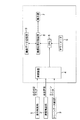
図1に示すように、本例のホイール式作業機械の表示装置は、走行判定部1と、速度検出部2と、クレーンデータ検出部3と、これら各検出部1,2,3の出力信号を受信する受信装置4と、アワーメータ5と、前記受信装置4の出力信号及び前記アワーメータ5の出力信号が入力される主制御部(CPU)6と、表示部7と、主制御部からの指令に基づいて所要の画像データを生成し、表示部7に表示する画像処理制御装置8と、画像処理制御装置8にて生成された画像データを記憶する画像データ記憶部9とから主に構成されている。
As shown in FIG. 1, the display device of the wheel type work machine of this example includes a travel determination unit 1, a
走行判定部1は、ホイール式作業機械が走行状態に切り換えられているか否かを検出するもので、例えばホイール式作業機械を走行状態又は非走行状態に切り換えるシフトレバーなどに備えられる。速度検出部2は、ホイール式作業機械の走行速度を検出するもので、例えばホイール式作業機械の車軸などに備えられる。クレーンデータ検出部3は、ホイール式作業機械がクレーンを用いた吊り作業状態に切り換えられているか否か、クレーン高さの現在値、クレーン半径の現在値、及び当該クレーンに作用している実荷重などを検出するもので、それぞれクレーンの所定の部位に備えられる。本例の表示装置を構成するその他の装置は、ホイール式作業機械の運転室内に備えられ、そのうち表示部7は、運転席に搭乗したオペレータが画面を視認できる位置に設置される。
The traveling determination unit 1 detects whether or not the wheel type work machine is switched to the traveling state, and is provided in, for example, a shift lever that switches the wheel type working machine to the traveling state or the non-traveling state. The
主制御部6は、受信装置4を介して走行判定部1から入力される走行判定フラグに基づいて、ホイール式作業機械が走行状態に切り換えられたか否かを判定する。また、主制御部6は、受信装置4を介してクレーンデータ検出部3から入力されるクレーンデータに基づいて、ホイール式作業機械が吊り作業状態に切り換えられたか否かを判定する。ホイール式作業機械が走行状態に切り換えられておらず、かつその運転状態が吊り作業状態に切り換えられていない場合には、図2(a)及び図3(a)に示す基本画面10が表示部7に表示される。また、ホイール式作業機械が走行状態に切り換えられておらず、かつその運転状態が吊り作業状態に切り換えられた場合には、図4(a)に示す吊り作業表示画面20が表示部7に表示される。
The
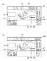
図2(a)及び図3(a)において、11はタコメータ表示画面、12は機体状態表示画面、13は作業状態表示画面、14は水温表示画面、15は燃料残量表示画面、16は現在時刻表示画面、17はアワーメータ表示画面である。また、図4(a)において、21は吊り作業状態表示画面、22はクレーンに作用している実荷重表示画面、23はクレーンの定格荷重表示画面、24はクレーン高さ表示画面、25はクレーン半径表示画面、26は作業状態表示画面、27は水温表示画面、28は燃料残量表示画面、29はアワーメータ表示画面である。これらの図に示すように、ホイール式作業機械が非走行状態にある場合、表示部7には、ホイール式作業機械の走行速度データを示す走行速度表示画面が表示されない。 2 (a) and 3 (a), 11 is a tachometer display screen, 12 is an aircraft state display screen, 13 is a work state display screen, 14 is a water temperature display screen, 15 is a remaining fuel amount display screen, and 16 is a current fuel display screen. A time display screen, 17 is an hour meter display screen. In FIG. 4A, 21 is a suspension work state display screen, 22 is an actual load display screen acting on the crane, 23 is a crane rated load display screen, 24 is a crane height display screen, and 25 is a crane. A radius display screen, 26 is a work state display screen, 27 is a water temperature display screen, 28 is a remaining fuel display screen, and 29 is an hour meter display screen. As shown in these drawings, when the wheeled work machine is in a non-traveling state, the traveling speed display screen showing the traveling speed data of the wheeled work machine is not displayed on the display unit 7.
主制御部6によってホイール式作業機械が非走行状態から走行状態に切り換えられたと判定されたとき、主制御部6は、画像処理制御装置8に、走行速度表示画面を生成して表示部7上に表示されている所定の画面を走行速度表示画面に切り換える指令を発する。画像処理制御装置8は、当該指令に応じて走行速度表示画面の生成と表示部7への表示とを行う。また、画像処理制御装置8にて生成された走行速度表示画面は、画像データ記憶部9に記憶される。
When it is determined by the
図2は、ホイール式作業機械が非走行状態にあり、かつその稼働状態が吊り作業状態にない状態から、主制御部6によりホイール式作業機械が走行状態に切り換えられたと判定された場合における表示部7に表示される画面の変化の第1例を示す図であって、図2(a)と図2(b)との比較から明らかなように、本例においては、基本画面10中のタコメータ表示画面11が、これと同種の円形メータの形式で表示された走行速度表示画面30Aに切り換えられている。基本画面10中のタコメータ表示画面11は、図2(a)に示すように、一般に円周上にエンジン回転数が目盛られた円形メータの形式で表示され、走行速度表示画面30も図2(b)に示すように円周上に走行速度が目盛られた円形メータの形式で表示することができるので、本例の場合、表示画面を切り換える際の各要素(オブジェクト)の変更を最小限にすることができ、画面の切り換えを円滑かつ違和感なく行うことができる。
FIG. 2 shows a display when the
図3は、ホイール式作業機械が非走行状態にあり、かつその稼働状態が吊り作業状態にない状態から、主制御部6によりホイール式作業機械が走行状態に切り換えられたと判定された場合における表示部7に表示される画面の変化の第2例を示す図であって、図3(a)と図3(b)との比較から明らかなように、本例においては、基本画面10中のアワーメータ表示画面17が、これと同種の数字の形式で表示された走行速度表示画面30Bに切り換えられている。基本画面10中のアワーメータ表示画面17は、図3(a)に示すように、一般に数字の形式で表示され、走行速度表示画面30Bも図3(b)に示すように数字の形式で表示することができるので、本例の場合も第1例と同様に、画面の切り換えを円滑かつ違和感なく行うことができる。
FIG. 3 shows a display when the
図4は、ホイール式作業機械が非走行状態にあり、かつその稼働状態が吊り作業状態にある状態から、主制御部6によりホイール式作業機械が走行状態に切り換えられたと判定された場合における表示部7に表示される画面の変化の第3例を示す図であって、図4(a)と図4(b)との比較から明らかなように、本例においては、吊り作業表示画面20中のアワーメータ表示画面29が、これと同種の数字の形式で表示された走行速度表示画面30Cに切り換えられている。吊り作業表示画面20中のアワーメータ表示画面29は、図4(a)に示すように、一般に数字の形式で表示され、走行速度表示画面30Cも図4(b)に示すように数字の形式で表示することができるので、本例の場合も第1例と同様に、画面の切り換えを円滑かつ違和感なく行うことができる。
FIG. 4 shows a display when the
1,2,3 検出部
6 主制御部(CPU)
7 表示部
8 画像処理制御装置
10 基本画面
11 タコメータ表示画面
17 アワーメータ表示画面
20 吊り作業表示画面
29 アワーメータ表示画面
30A,30B,30C 走行速度表示画面
1, 2, 3
7
Claims (5)
前記検出部は、前記ホイール式作業機械が走行状態にあるか否か、及び作業状態にあるか否かを検出し、
前記制御部は、前記検出部によって検出される前記ホイール式作業機械の走行状態又は非走行状態並びに作業状態又は非作業状態に基づき、前記表示部にタコメータ表示画面を含む複数の表示画面を表示する基本画面と、前記基本画面に表示される表示画面とは異なる作業状態表示画面を含む複数の表示画面を表示する作業表示画面とを選択的に表示すると共に、前記表示部に前記基本画面又は前記作業表示画面が表示されているときに、前記走行状態に切り換えられていないと判定した場合には、前記基本画面又は前記作業表示画面に走行速度表示画面を表示せず、前記表示部に前記基本画面が表示されているときに、前記走行状態に切り換えられたと判定した場合には、前記基本画面に表示されている複数の表示画面のうちの一部を、それと同種の形式で表示される走行速度表示画面に切り換えることを特徴とするホイール式作業機械の表示装置。 A display unit that is provided in a cab of the wheel type work machine, displays a state of the state of the wheel type work machine, and a detection unit that detects a state of each part of the wheel type work machine and outputs the state as an output signal; In the display device of the wheel type work machine comprising the control unit that receives the output signal and controls a screen displayed on the display unit according to the received output signal,
The detection unit detects whether the wheeled work machine is in a running state and whether it is in a working state;
The control unit displays a plurality of display screens including a tachometer display screen on the display unit based on a running state or a non-running state of the wheel type work machine and a working state or a non-working state detected by the detection unit. Selectively displaying a basic screen and a work display screen for displaying a plurality of display screens including a work state display screen different from the display screen displayed on the basic screen, and displaying the basic screen or the When it is determined that the operation state is not switched to the traveling state when the work display screen is displayed, the traveling speed display screen is not displayed on the basic screen or the work display screen, and the basic unit is not displayed on the display unit. If it is determined that the driving state has been switched while the screen is displayed, a part of the plurality of display screens displayed on the basic screen is displayed. Display device of a wheel type working machine, characterized in that switching to the running speed display screen to be displayed in a homogeneous format.
前記制御部は、前記表示部に前記基本画面又は前記作業表示画面が表示されているときに、前記走行状態に切り換えられていないと判定した場合には、前記基本画面又は前記作業表示画面に走行速度表示画面を表示せず、前記走行状態に切り換えられたと判定した場合には、前記基本画面又は前記作業表示画面に表示されている複数の表示画面のうちの一部を、それと同種の形式で表示される走行速度表示画面に切り換えることを特徴とするホイール式作業機械の表示装置。 In the display device of the wheel type work machine according to claim 1,
The control unit travels to the basic screen or the work display screen when it is determined that the basic screen or the work display screen is displayed on the display unit and is not switched to the travel state. If it is determined that the driving state has been switched to without displaying the speed display screen, a part of the plurality of display screens displayed on the basic screen or the work display screen is displayed in the same type as that. wheel type working machine of a display device and wherein the switching to the running speed display screen displayed.
前記制御部は、前記ホイール式作業機械が走行状態に切り換えられたと判定した場合、前記ホイール式作業機械が走行状態に切り換えられていないと判定した場合に前記表示部に表示されていた前記基本画面中のタコメータ表示画面を、走行速度表示画面に切り換えることを特徴とするホイール式作業機械の表示装置。 In the display device of the wheel type work machine according to claim 1 or 2 ,
When the control unit determines that the wheel type work machine has been switched to the running state, the control unit displays the basic screen displayed on the display unit when the wheel type work machine determines that the wheel type work machine has not been switched to the running state. A display device for a wheel type work machine, wherein a tachometer display screen in the inside is switched to a traveling speed display screen.
前記制御部は、前記ホイール式作業機械が走行状態に切り換えられたと判定した場合、前記ホイール式作業機械が走行状態に切り換えられていないと判定した場合に前記表示部に表示されていた前記基本画面中のアワーメータ表示画面を、走行速度表示画面に切り換えることを特徴とするホイール式作業機械の表示装置。 In the display device of the wheel type work machine according to claim 1 or 2 ,
When the control unit determines that the wheel type work machine has been switched to the running state, the control unit displays the basic screen displayed on the display unit when the wheel type work machine determines that the wheel type work machine has not been switched to the running state. A display device for a wheel type work machine, wherein the hour meter display screen in the inside is switched to a traveling speed display screen.
前記作業表示画面は、吊り作業表示画面であり、 The work display screen is a hanging work display screen,
前記制御部は、前記ホイール式作業機械が走行状態に切り換えられたと判定した場合、前記ホイール式作業機械が前記作業状態に切り換えられたと判定した場合に前記表示部に表示されていた前記吊り作業表示画面中のアワーメータ表示画面を、走行速度表示画面に切り換えることを特徴とするホイール式作業機械の表示装置。 When the control unit determines that the wheel type work machine has been switched to a running state, the control unit displays the suspension work display displayed on the display unit when the wheel type work machine has been determined to have been switched to the work state. A display device for a wheel type work machine, wherein the hour meter display screen in the screen is switched to a traveling speed display screen.
Priority Applications (1)
| Application Number | Priority Date | Filing Date | Title |
|---|---|---|---|
| JP2006104188A JP4498302B2 (en) | 2006-04-05 | 2006-04-05 | Display device for wheel type work machine |
Applications Claiming Priority (1)
| Application Number | Priority Date | Filing Date | Title |
|---|---|---|---|
| JP2006104188A JP4498302B2 (en) | 2006-04-05 | 2006-04-05 | Display device for wheel type work machine |
Publications (2)
| Publication Number | Publication Date |
|---|---|
| JP2007276585A JP2007276585A (en) | 2007-10-25 |
| JP4498302B2 true JP4498302B2 (en) | 2010-07-07 |
Family
ID=38678508
Family Applications (1)
| Application Number | Title | Priority Date | Filing Date |
|---|---|---|---|
| JP2006104188A Expired - Fee Related JP4498302B2 (en) | 2006-04-05 | 2006-04-05 | Display device for wheel type work machine |
Country Status (1)
| Country | Link |
|---|---|
| JP (1) | JP4498302B2 (en) |
Families Citing this family (4)
| Publication number | Priority date | Publication date | Assignee | Title |
|---|---|---|---|---|
| JP4713600B2 (en) * | 2008-01-25 | 2011-06-29 | 住友建機株式会社 | Display system for construction machinery |
| JP5011150B2 (en) * | 2008-02-07 | 2012-08-29 | 日立建機株式会社 | Display device for work vehicle |
| WO2015088048A1 (en) | 2014-12-26 | 2015-06-18 | 株式会社小松製作所 | Work machine status information display device, work machine warning display method, and work machine warning display program |
| JP6022694B2 (en) * | 2014-12-26 | 2016-11-09 | 株式会社小松製作所 | Wheel system work vehicle status information display device, wheel system work vehicle maintenance inspection screen display method, and wheel system work vehicle maintenance inspection screen display program |
Citations (8)
| Publication number | Priority date | Publication date | Assignee | Title |
|---|---|---|---|---|
| JPH03273946A (en) * | 1990-03-22 | 1991-12-05 | Nippon Seiki Co Ltd | Display device for vehicle |
| JPH0616915A (en) * | 1992-07-03 | 1994-01-25 | Teijin Ltd | Antistatic polyester composition |
| JPH07103782A (en) * | 1993-10-04 | 1995-04-18 | Seiko Epson Corp | Image data operation device for vehicle |
| JPH095120A (en) * | 1995-06-15 | 1997-01-10 | Moriyama Kogyo Kk | Meter-display changeover device |
| JP2002205572A (en) * | 2001-01-10 | 2002-07-23 | Honda Motor Co Ltd | Vehicular meter device |
| JP2002274466A (en) * | 2001-01-10 | 2002-09-25 | Honda Motor Co Ltd | Meter device for vehicle |
| JP2003082710A (en) * | 2001-09-04 | 2003-03-19 | Hitachi Constr Mach Co Ltd | Construction machine |
| JP2006016915A (en) * | 2004-07-05 | 2006-01-19 | Hitachi Constr Mach Co Ltd | Display device for construction machine |
-
2006
- 2006-04-05 JP JP2006104188A patent/JP4498302B2/en not_active Expired - Fee Related
Patent Citations (8)
| Publication number | Priority date | Publication date | Assignee | Title |
|---|---|---|---|---|
| JPH03273946A (en) * | 1990-03-22 | 1991-12-05 | Nippon Seiki Co Ltd | Display device for vehicle |
| JPH0616915A (en) * | 1992-07-03 | 1994-01-25 | Teijin Ltd | Antistatic polyester composition |
| JPH07103782A (en) * | 1993-10-04 | 1995-04-18 | Seiko Epson Corp | Image data operation device for vehicle |
| JPH095120A (en) * | 1995-06-15 | 1997-01-10 | Moriyama Kogyo Kk | Meter-display changeover device |
| JP2002205572A (en) * | 2001-01-10 | 2002-07-23 | Honda Motor Co Ltd | Vehicular meter device |
| JP2002274466A (en) * | 2001-01-10 | 2002-09-25 | Honda Motor Co Ltd | Meter device for vehicle |
| JP2003082710A (en) * | 2001-09-04 | 2003-03-19 | Hitachi Constr Mach Co Ltd | Construction machine |
| JP2006016915A (en) * | 2004-07-05 | 2006-01-19 | Hitachi Constr Mach Co Ltd | Display device for construction machine |
Also Published As
| Publication number | Publication date |
|---|---|
| JP2007276585A (en) | 2007-10-25 |
Similar Documents
| Publication | Publication Date | Title |
|---|---|---|
| JP5587032B2 (en) | Vehicle display device | |
| CN102596627B (en) | Display device for vehicle | |
| JP5236872B2 (en) | Work vehicle | |
| JP5586568B2 (en) | Construction machine information display device, construction machine information display method, and construction machine information display computer program | |
| JP6067858B2 (en) | Work machine status information display device, work machine warning display method, and work machine warning display program | |
| JP4498302B2 (en) | Display device for wheel type work machine | |
| KR20130069732A (en) | Display unit of work machine and work machine mounted with the display unit | |
| KR20160000428A (en) | Method and device for displaying in a vehicle at least one parameter relating to the operation of the vehicle | |
| JP2010030331A (en) | Vehicle display device | |
| JP2019506655A5 (en) | ||
| JP2004136823A (en) | Display device for vehicle | |
| JP7043965B2 (en) | Vehicle information display device | |
| JP4817620B2 (en) | Construction machine display device | |
| JP2007210462A (en) | Display control device for vehicle and display system for vehicle | |
| JP6052865B2 (en) | In-vehicle display control device and in-vehicle display control method | |
| JP4958543B2 (en) | Display device for wheel type work machine | |
| JP4045972B2 (en) | Display control device for vehicle | |
| JP4596910B2 (en) | Vehicle information display device | |
| JP5011150B2 (en) | Display device for work vehicle | |
| WO2014203888A1 (en) | Display device | |
| JP6079155B2 (en) | Display control device | |
| JP5554630B2 (en) | Construction machine display device | |
| JP6022694B2 (en) | Wheel system work vehicle status information display device, wheel system work vehicle maintenance inspection screen display method, and wheel system work vehicle maintenance inspection screen display program | |
| US20150091782A1 (en) | Display Device for Vehicle | |
| JP2005022615A (en) | Alarm information displaying device |
Legal Events
| Date | Code | Title | Description |
|---|---|---|---|
| A621 | Written request for application examination |
Free format text: JAPANESE INTERMEDIATE CODE: A621 Effective date: 20080513 |
|
| A977 | Report on retrieval |
Free format text: JAPANESE INTERMEDIATE CODE: A971007 Effective date: 20091126 |
|
| A131 | Notification of reasons for refusal |
Free format text: JAPANESE INTERMEDIATE CODE: A131 Effective date: 20091201 |
|
| A521 | Request for written amendment filed |
Free format text: JAPANESE INTERMEDIATE CODE: A523 Effective date: 20100129 |
|
| A521 | Request for written amendment filed |
Free format text: JAPANESE INTERMEDIATE CODE: A523 Effective date: 20100212 |
|
| TRDD | Decision of grant or rejection written | ||
| A01 | Written decision to grant a patent or to grant a registration (utility model) |
Free format text: JAPANESE INTERMEDIATE CODE: A01 Effective date: 20100330 |
|
| A01 | Written decision to grant a patent or to grant a registration (utility model) |
Free format text: JAPANESE INTERMEDIATE CODE: A01 |
|
| A61 | First payment of annual fees (during grant procedure) |
Free format text: JAPANESE INTERMEDIATE CODE: A61 Effective date: 20100413 |
|
| FPAY | Renewal fee payment (event date is renewal date of database) |
Free format text: PAYMENT UNTIL: 20130423 Year of fee payment: 3 |
|
| R150 | Certificate of patent or registration of utility model |
Ref document number: 4498302 Country of ref document: JP Free format text: JAPANESE INTERMEDIATE CODE: R150 Free format text: JAPANESE INTERMEDIATE CODE: R150 |
|
| FPAY | Renewal fee payment (event date is renewal date of database) |
Free format text: PAYMENT UNTIL: 20140423 Year of fee payment: 4 |
|
| LAPS | Cancellation because of no payment of annual fees |