JP4497145B2 - Control device for vehicle generator - Google Patents
Control device for vehicle generator Download PDFInfo
- Publication number
- JP4497145B2 JP4497145B2 JP2006242787A JP2006242787A JP4497145B2 JP 4497145 B2 JP4497145 B2 JP 4497145B2 JP 2006242787 A JP2006242787 A JP 2006242787A JP 2006242787 A JP2006242787 A JP 2006242787A JP 4497145 B2 JP4497145 B2 JP 4497145B2
- Authority
- JP
- Japan
- Prior art keywords
- deceleration
- vehicle
- generator
- battery
- voltage
- Prior art date
- Legal status (The legal status is an assumption and is not a legal conclusion. Google has not performed a legal analysis and makes no representation as to the accuracy of the status listed.)
- Expired - Fee Related
Links
Images


Landscapes
- Control Of Charge By Means Of Generators (AREA)
- Control Of Eletrric Generators (AREA)
Description
本発明は、車両用発電機の制御装置に関するものである。 The present invention relates to a control device for a vehicular generator.
従来より、車両減速時と非減速時とで、エンジンにより駆動されて少なくともバッテリに給電する発電機の発電電圧を変えることによって制動エネルギの回生と燃費の向上を図る車両用発電機の制御装置が知られている。例えば、特許文献1のものでは、車両の減速時に、発電機の発電電圧を車両の非減速時よりも高くすることによって、車両の減速時には制動エネルギーの回生を積極的に行う一方、車両の非減速時にはエンジンへの負荷を低減させて燃費の向上を図るようになっている。 2. Description of the Related Art Conventionally, a control device for a vehicular generator that regenerates braking energy and improves fuel efficiency by changing a power generation voltage of a generator that is driven by an engine and supplies power to at least a battery depending on whether the vehicle is decelerated or not decelerated. Are known. For example, in Patent Document 1, when the vehicle decelerates, the power generation voltage of the generator is made higher than when the vehicle is not decelerated, so that braking energy is regenerated actively when the vehicle decelerates, while During deceleration, the load on the engine is reduced to improve fuel efficiency.
ここで、発電機の発電電圧を高くすると、発電機はエンジンによって駆動されているためエンジンへの負荷が増大し、その結果、エンジンブレーキ力が増加する。
ところで、運転者が要求する車両の減速度は、運転者によってそれぞれ異なる。それにも拘わらず、車両の減速時に、例えば、発電機の発電電圧を一律に車両の非減速時よりも一定電圧だけ高くすると、エンジンブレーキ力は一様に車両の非減速時よりも所定の大きさだけ増加し、その結果、車両の要求減速度と車両の実際の減速度とが相違する場合がある。このため、運転者が要求する減速感を実現することができないおそれがある。 By the way, the vehicle deceleration required by the driver differs depending on the driver. Nevertheless, when the vehicle decelerates, for example, if the generator's generated voltage is uniformly increased by a constant voltage compared to when the vehicle is not decelerated, the engine braking force is uniformly larger than that when the vehicle is not decelerated. As a result, the required deceleration of the vehicle may differ from the actual deceleration of the vehicle. For this reason, there is a possibility that the feeling of deceleration requested by the driver cannot be realized.
本発明は、かかる点に鑑みてなされたものであり、その目的とするところは、車両用発電機の制御装置において、制動エネルギの回生と燃費の向上を図りながら、運転者が要求する減速感を実現することにある。 The present invention has been made in view of the above points, and an object of the present invention is to provide a vehicle generator control device with a feeling of deceleration required by the driver while regenerating braking energy and improving fuel consumption. Is to realize.
第1の発明は、車両の減速時に、エンジンにより駆動されて少なくともバッテリに給電する発電機の発電電圧を上記車両の非減速時よりも高くする発電電圧制御手段を備えた車両用発電機の制御装置であって、ブレーキ操作状態に基づき、上記車両の要求減速度を判定する要求減速度判定手段を備え、上記発電電圧制御手段は、上記車両の減速時であって、上記要求減速度判定手段により判定された要求減速度が所定減速度よりも大きいときには、該要求減速度が大きいほど上記発電機の発電電圧を高くする一方、上記車両の減速時であって、上記要求減速度判定手段により判定された要求減速度が上記所定減速度以下で且つ上記バッテリが低充電状態のときには、上記発電機の発電電圧を上記バッテリへの充電を促進する電圧にするように構成され、上記車両の減速時であって、上記要求減速度判定手段により判定された要求減速度が上記所定減速度以下で且つ上記バッテリが上記低充電状態のときに、該要求減速度と上記車両の実際の減速度とが相違するのを抑制する抑制手段をさらに備えたことを特徴とするものである。 1st invention controls the generator for vehicles provided with the generation voltage control means which makes the power generation voltage of the power generator which is driven by an engine and feeds at least a battery at the time of deceleration of a vehicle higher than the time of non-deceleration of the above-mentioned vehicle. And a required deceleration determining means for determining a required deceleration of the vehicle based on a brake operation state, wherein the generated voltage control means is at the time of deceleration of the vehicle, and the required deceleration determining means. Is larger than the predetermined deceleration, the higher the required deceleration, the higher the power generation voltage of the generator. On the other hand, when the vehicle is decelerating, the requested deceleration determining means When the determined required deceleration is not more than the predetermined deceleration and the battery is in a low charge state, the power generation voltage of the generator is set to a voltage that promotes charging of the battery. And when the vehicle is decelerating, the requested deceleration determined by the requested deceleration determining means is equal to or less than the predetermined deceleration and the battery is in the low charge state. Further, it is characterized by further comprising suppression means for suppressing the difference from the actual deceleration of the vehicle .
これにより、車両の減速時であって、要求減速度判定手段により判定された要求減速度が所定減速度よりも大きいときには、発電電圧制御手段により、該要求減速度が大きいほどエンジンにより駆動される発電機の発電電圧を高くするので、その要求減速度が大きいほどエンジンブレーキ力は増加し、その結果、車両の要求減速度と車両の実際の減速度とが相違することを抑制することができる。このため、制動エネルギの回生と燃費の向上を図りながら、運転者が要求する減速感を実現することができる。 Thus, a time of deceleration of the vehicle, when the request deceleration determined by the required deceleration determining means is greater than a predetermined deceleration, the generated voltage control means, driven by the engine as the request deceleration is large Since the power generation voltage of the generator is increased, the engine braking force increases as the required deceleration increases, and as a result, the difference between the required deceleration of the vehicle and the actual deceleration of the vehicle can be suppressed. . For this reason, it is possible to realize the feeling of deceleration required by the driver while improving the braking energy and improving the fuel consumption.
ところで、車両の減速時であって、車両の要求減速度が所定減速度以下で且つバッテリが低充電状態のときには、バッテリへの充電を促進したいが、発電機の発電電圧をバッテリへの充電を促進する電圧にすると、エンジンブレーキ力が増加し、その結果、その要求減速度が比較的低いにも拘わらず、車両の実際の減速度が大きくなり、運転者が要求する減速感を実現することができないおそれがある。By the way, when the vehicle is decelerating and the required deceleration of the vehicle is equal to or less than the predetermined deceleration and the battery is in a low charge state, it is desired to promote the charging of the battery, but the generated voltage of the generator is charged to the battery. When the voltage is increased, the engine braking force increases, and as a result, the actual deceleration of the vehicle is increased even though the required deceleration is relatively low, thereby realizing the feeling of deceleration required by the driver. You may not be able to.
ここで、本発明によれば、車両の減速時であって、要求減速度判定手段により判定された車両の要求減速度が所定減速度以下で且つバッテリが低充電状態のときには、抑制手段により、該要求減速度と車両の実際の減速度とが相違するのを抑制するので、車両の減速時であって、その要求減速度が比較的低く且つバッテリが低充電状態のときに、発電機の発電電圧をバッテリへの充電を促進する電圧にしても、車両の要求減速度と車両の実際の減速度とが相違することを抑制することができる。このため、車両の減速時であって、その要求減速度が比較的低く且つバッテリが低充電状態のときに、バッテリへの充電を促進しながら、運転者が要求する減速感を実現することができる。Here, according to the present invention, when the vehicle is decelerating, when the required deceleration of the vehicle determined by the required deceleration determination means is equal to or less than a predetermined deceleration and the battery is in a low charge state, the suppression means Since the difference between the required deceleration and the actual deceleration of the vehicle is suppressed, when the vehicle is decelerated, when the required deceleration is relatively low and the battery is in a low charge state, Even if the generated voltage is a voltage that promotes charging of the battery, it is possible to suppress the difference between the required deceleration of the vehicle and the actual deceleration of the vehicle. Therefore, when the vehicle is decelerating and the required deceleration is relatively low and the battery is in a low charge state, it is possible to realize the feeling of deceleration required by the driver while promoting the charging of the battery. it can.
第2の発明は、上記第1の発明において、上記要求減速度判定手段は、上記ブレーキ操作状態としての所定期間内におけるブレーキ回数又は平均ブレーキ操作力に基づき、上記車両の要求減速度を判定するように構成されていることを特徴とするものである。 In a second aspect based on the first aspect, the required deceleration determining means determines the required deceleration of the vehicle based on the number of brakes or an average brake operating force within a predetermined period as the brake operating state. It is comprised so that it may be comprised.
これにより、要求減速度判定手段により、所定期間内におけるブレーキ回数又は平均ブレーキ操作力に基づき、車両の要求減速度を判定するので、車両の要求減速度を正確に判定することができる。 Thereby, the required deceleration of the vehicle is determined by the required deceleration determination means based on the number of brakes or the average brake operation force within a predetermined period, so that the required deceleration of the vehicle can be accurately determined.
第3の発明は、上記第1の発明において、上記抑制手段は、上記車両の減速時であって、上記要求減速度判定手段により判定された要求減速度が上記所定減速度以下で且つ上記バッテリが上記低充電状態のときには、変速機を強制的にアップシフトさせる又は上記発電機により給電される電気負荷を一時的に停止することにより該要求減速度と上記車両の実際の減速度とが相違するのを抑制するように構成されていることを特徴とするものである。 In a third aspect based on the first invention, the upper Kisomosomo system means is a deceleration of the vehicle, required deceleration is determined by the required deceleration determining means and below said predetermined deceleration When the battery is in the low charge state, the required deceleration and the actual deceleration of the vehicle are obtained by forcibly upshifting the transmission or temporarily stopping the electric load supplied by the generator. It is characterized by being comprised so that difference may be suppressed.
これにより、車両の減速時であって、要求減速度判定手段により判定された車両の要求減速度が所定減速度以下で且つバッテリが低充電状態のときには、抑制手段により、変速機を強制的にアップシフトさせる又は発電機により給電される電気負荷を一時的に停止するので、エンジンブレーキ力が減少する。このため、車両の減速時であって、その要求減速度が比較的低く且つバッテリが低充電状態のときに、発電機の発電電圧をバッテリへの充電を促進する電圧にしても、車両の要求減速度と車両の実際の減速度とが相違することを抑制することができる。したがって、車両の減速時であって、その要求減速度が比較的低く且つバッテリが低充電状態のときに、バッテリへの充電を促進しながら、運転者が要求する減速感を実現することができる。 Accordingly, a deceleration of the vehicle, when the request deceleration of the vehicle determined by the required deceleration determining means and the battery below a predetermined deceleration of the low charge state, the suppression means, force the transmission Therefore, the engine braking force is reduced because the electrical load supplied by the generator is temporarily stopped. For this reason, even when the vehicle is decelerating and the required deceleration is relatively low and the battery is in a low charge state, even if the power generation voltage of the generator is set to a voltage that promotes charging of the battery, the vehicle request It is possible to suppress the difference between the deceleration and the actual deceleration of the vehicle. Therefore, when the vehicle is decelerating and the required deceleration is relatively low and the battery is in a low charge state, it is possible to realize the feeling of deceleration required by the driver while promoting the charging of the battery. .
本発明によれば、車両の減速時であって、要求減速度が所定減速度よりも大きいときには、該要求減速度が大きいほどエンジンにより駆動される発電機の発電電圧を高くするので、その要求減速度が大きいほどエンジンブレーキ力は増加し、その結果、車両の要求減速度と車両の実際の減速度とが相違することを抑制することができ、このため、制動エネルギの回生と燃費の向上を図りながら、運転者が要求する減速感を実現することができる。 According to the present invention, when the vehicle is decelerating and the required deceleration is greater than the predetermined deceleration , the power generation voltage of the generator driven by the engine is increased as the required deceleration increases. The greater the deceleration, the greater the engine braking force. As a result, it is possible to suppress the difference between the required deceleration of the vehicle and the actual deceleration of the vehicle, thus improving braking energy regeneration and fuel efficiency. It is possible to realize the feeling of deceleration required by the driver.
以下、本発明の実施形態を図面に基づいて詳細に説明する。 Hereinafter, embodiments of the present invention will be described in detail with reference to the drawings.
(参考例1)
図1は、本発明の参考例1に係る車両用発電機の制御装置の概略構成図である。符号1はエンジンであり、符号2はエンジン1の冷却ファンとエアコンディショナーのコンプレッサーとからなる車両電気負荷51及びバッテリ52に給電する発電機(オルタネーター)であり、符号3は発電機2の発電電圧を制御する制御手段である。
( Reference Example 1)
FIG. 1 is a schematic configuration diagram of a control device for a vehicular generator according to Reference Example 1 of the present invention. Reference numeral 1 denotes an engine,
発電機2は、補機駆動ベルト1aを介してエンジン1のクランクシャフト1bに設けられたクランクプーリ(図示省略)に連結されていて、クランクシャフト1bにより回転駆動される。
The
制御手段3には、発電機2及び電気負荷51が接続されると共に、運転者のアクセルペダルの踏み込み量(アクセル開度)を検出するアクセル開度センサ41と、車両の車速を検出する車速センサ42と、ブレーキ装置のオイル通路の圧力を検出するブレーキ油圧センサ43と、バッテリ52の電流の強さ及び電圧を検出するバッテリ電流/電圧センサ44とが信号を授受可能に接続されている。
The control means 3 is connected to the
また、制御手段3は、車両の減速状態を検出する減速状態検出部31と、車両の要求減速度(要求減速度合)を判定する要求減速度判定部32(要求減速度判定手段に相当)と、発電機2の発電電圧を記憶している記憶部33と、発電機2の発電電圧を制御する発電電圧制御部34(発電電圧制御手段に相当)と、バッテリ52の満充電状態を検出する満充電状態検出部35と、電気負荷51を制御する電気負荷制御部36(電気負荷制御手段に相当)とを有する。
The
上記減速状態検出部31は、アクセル開度センサ41及び車速センサ42からの検出信号を受けて、車両が減速状態か否かを判定して、減速状態であるときには減速状態信号を発電電圧制御部34及び電気負荷制御部36へ出力する。
The deceleration
上記要求減速度判定部32は、ブレーキ油圧センサ43からの検出信号を受けて所定期間内におけるブレーキ回数(ブレーキ頻度)を検出し、この検出したブレーキ回数に基づいて要求減速度を判定し、この判定した要求減速度に関する要求減速度信号を発電電圧制御部34へ出力する。要求減速度判定部32は、所定期間内におけるブレーキ回数が多いほど要求減速度が高いと判定するようになっている。
The requested
上記記憶部33には、後述の発電電圧制御で用いる、バッテリ52の充電を促進する充電促進電圧と、バッテリ52の充電を抑制する充電抑制電圧とが記憶されている。この充電促進電圧は、充電抑制電圧よりも高くなっている。さらに詳しくは、記憶部33は、図2に示すように、発電電圧マップを有する。この発電電圧マップは、要求減速度(すなわち、ブレーキ頻度)をパラメータとしている。そして、要求減速度が大きいほど、これに比例するように充電促進電圧は高くなる。充電促進電圧は、本参考例においては13Vから15Vの範囲内の電圧が記憶されている。そして、記憶部33は、後述の発電電圧制御で詳しく説明するが、減速状態検出部31からの減速状態信号と、要求減速度判定部32からの要求減速度信号とを受けて、充電促進電圧を更新して記憶する。一方、充電抑制電圧は12.6Vが記憶されており、その後更新されることもなく一定である。
The
上記発電電圧制御部34は、減速状態検出部31からの減速状態信号と、要求減速度判定部32からの要求減速度信号とを受けて、車両が減速しているときには要求減速度に基づいて充電促進電圧を記憶部33から読み出し且つ発電機2の発電電圧をその充電促進電圧に制御する一方、車両が減速していないときには充電抑制電圧を記憶部33から読み出し且つ発電機2の発電電圧をその充電抑制電圧に制御する。
The generated
上記満充電状態検出部35は、バッテリ電流/電圧センサ44からの検出信号を受けて、バッテリ52が満充電状態か否かを判定し、満充電状態であるときには満充電状態信号を電気負荷制御部36へ出力する。なお、満充電状態とは、バッテリ52の充電量がバッテリ52の最大許容充電量になった状態をいう。
The full charge
上記電気負荷制御部36は、減速状態検出部31からの減速状態信号と、満充電状態検出部35からの満充電状態信号とを受けて、車両が減速している場合であってバッテリ52が満充電状態のときには電気負荷51を強制的に作動させる。
The electric
−車両用発電機の制御装置における発電電圧制御−
以下、図3のフローチャートを参照しながら、車両用発電機の制御装置における発電電圧制御について説明する。
-Generation voltage control in vehicle generator control devices-
Hereinafter, the generated voltage control in the control device for the vehicle generator will be described with reference to the flowchart of FIG.
まず、ステップS1において、アクセル開度センサ41と車速センサ42とブレーキ油圧センサ43とバッテリ電流/電圧センサ44とから各種検出信号を読み込む。
First, in step S <b> 1, various detection signals are read from the
次に、ステップS2において、車両が減速状態か否かを判定する。詳しくは、減速状態検出部31が、アクセル開度センサ41及び車速センサ42からの検出信号に基づいて、エンジンのアクセル開度が全閉である、および車速が所定速度以上である、という2条件が共に成立か否かを判定し、この2条件が共に成立するときには車両が減速状態であると判定して、減速状態信号を発電電圧制御部34及び電気負荷制御部36に出力する。そして、減速状態であると判定されたとき(YES)にはステップS3へ進む一方、車両が減速していない非減速状態であると判定されたとき(NO)にはステップS5へ進む。
Next, in step S2, it is determined whether or not the vehicle is in a deceleration state. Specifically, the deceleration
減速状態であるステップS3においては、所定期間内におけるブレーキ回数に基づき、車両の要求減速度を算出する。詳しくは、要求減速度判定部32が、ブレーキ油圧センサ43からの検出信号に基づいて所定期間内におけるブレーキ回数を検出し、この検出したブレーキ回数に基づいて要求減速度を判定し、この判定した要求減速度に関する要求減速度信号を発電電圧制御部34へ出力する。
In step S3, which is a deceleration state, the required deceleration of the vehicle is calculated based on the number of brakes within a predetermined period. Specifically, the required
次に、ステップS4において、発電機2の発電電圧をバッテリ52の充電を促進する充電促進電圧に制御する。詳しくは、発電電圧制御部34は、減速状態検出部31から出力される減速状態信号が入力されたときに、要求減速度判定部32から出力される要求減速度信号を受けて、該要求減速度信号に基づいて要求減速度情報を取得すると共に、この要求減速度情報と記憶部33に記憶されている発電電圧マップとを照合して、該要求減速度に応じた充電促進電圧を読み出す。そして、発電電圧制御部34は、発電機2の発電電圧を記憶部33から読み出した充電促進電圧に制御する。その後、ステップS6へ進む。
Next, in step S <b> 4, the power generation voltage of the
一方、非減速状態であるステップS5においては、発電機2の発電電圧をバッテリ52の充電を抑制する充電抑制電圧に制御する。詳しくは、発電電圧制御部34は、記憶部33に記憶されている充電抑制電圧を読み出すと共に、発電機2の発電電圧をその充電抑制電圧に制御する。充電抑制電圧は一定(本参考例では12.6V)であり、その後リターンへ進んでスタートに戻る。
On the other hand, in step S <b> 5, which is a non-decelerated state, the power generation voltage of the
そして、ステップS6においては、バッテリ52が満充電状態か否かを判定する。詳しくは、満充電状態検出部35が、バッテリ電流/電圧センサ44からの検出信号に基づいてバッテリ52が満充電状態か否かを判定し、満充電状態であるときには満充電状態信号を発電電圧制御部34に出力する。そして、満充電状態であると判定されたとき(YES)にはステップS7へ進む一方、満充電状態でないと判定されたとき(NO)にはリターンへ進んでスタートに戻る。
In step S6, it is determined whether or not the
満充電状態であるステップS7においては、電気負荷51を強制的に作動させる。詳しくは、電気負荷制御部36が、減速状態検出部31から出力される減速状態信号が入力されたときに、満充電状態検出部35から出力される満充電状態信号を受けて、電気負荷51を強制的に作動させる。その後、リターンへ進んでスタートに戻る。
In step S7 in the fully charged state, the
−効果−
以上により、本参考例によれば、車両の減速時には、発電電圧制御部34により、要求減速度判定部32により判定された車両の要求減速度が大きいほどエンジン1により駆動される発電機2の発電電圧を高くするので、その要求減速度が大きいほどエンジンブレーキ力は増加し、その結果、車両の要求減速度と車両の実際の減速度とが相違することを抑制することができる。このため、制動エネルギの回生と燃費の向上を図りながら、運転者が要求する減速感を実現することができる。
-Effect-
As described above, according to the present reference example , when the vehicle is decelerated, the
また、要求減速度判定部32により、所定期間内におけるブレーキ回数に基づき、車両の要求減速度を判定するので、車両の要求減速度を正確に判定することができる。
Further, since the required
また、車両の減速時であって、バッテリ52が満充電状態のときには、電気負荷制御部36により、発電機2により給電される電気負荷51を強制的に作動させるので、発電機2によりバッテリ52に給電される電力を小さくすることができる。このため、バッテリ52が満充電状態にも拘わらず、車両の減速時に、発電機2の発電電圧を車両の非減速時よりも高くすることができる。
Further, when the vehicle is decelerating and the
なお、本参考例では、電気負荷51をエンジン1の冷却ファンとエアコンディショナーのコンプレッサーとで構成しているが、これら以外のもので構成しても良い。但し、作動しても運転者に違和感を与えないものが望ましい。
In this reference example , the
また、本参考例では、車両が減速している場合であってバッテリ52が満充電状態のときに、電気負荷51を強制的に作動させているが、作動させなくても良い。但し、バッテリ52の過充電を抑制するには、作動させるのが望ましい。
In this reference example , the
(実施形態1)
本実施形態は、車両が減速し、車両の要求減速度が所定減速度以下で且つバッテリ52が低充電状態のときに、変速機53を強制的にアップシフトさせるものである。以下、参考例1との相違点について説明する。
(Embodiment 1 )
In the present embodiment, the
図4は、本発明の実施形態1に係る車両用発電機の制御装置の概略構成図である。制御手段3は、減速状態検出部31と、要求減速度判定部32と、記憶部33と、発電電圧制御部34と、バッテリ52の低充電状態を検出する低充電状態検出部37と、変速機52を制御する変速機制御部38(抑制手段に相当)とを有する。
FIG. 4 is a schematic configuration diagram of the control device for the vehicle generator according to the first embodiment of the present invention. The control means 3 includes a deceleration
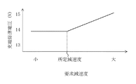
上記記憶部33は、図5に示すように、発電電圧マップを有する。この発電電圧マップは、要求減速度をパラメータとしている。そして、要求減速度が所定減速度以下であると、充電促進電圧は一定電圧である一方、要求減速度が所定減速度よりも大きいと、要求減速度が大きいほどこれに比例するように充電促進電圧は高くなる。充電促進電圧は、本実施形態においては13Vから15Vの範囲内の電圧が記憶されている。そして、記憶部33は、後述の発電電圧制御で詳しく説明するが、減速状態検出部31からの減速状態信号と、要求減速度判定部32からの要求減速度信号とを受けて、充電促進電圧を更新して記憶する。一方、充電抑制電圧は12.6Vが記憶されており、その後更新されることもなく一定である。
The
上記低充電状態検出部37は、バッテリ電流/電圧センサ44からの検出信号を受けて、バッテリ52が低充電状態か否かを判定し、低充電状態であるときには低充電状態信号を発電電圧制御部34及び電気負荷制御部36へ出力する。なお、低充電状態とは、バッテリ52の電圧が所定電圧(本実施形態では10V)よりも低くなった状態、つまり、バッテリ52の充電量が所定充電量よりも小さくなった状態をいう。
The low charge
上記発電電圧制御部34は、減速状態検出部31からの減速状態信号と、要求減速度判定部32からの要求減速度信号と、低充電状態検出部37からの低充電状態信号とを受けて、車両が減速し且つ要求減速度が所定減速度よりも大きいときには該要求減速度に基づいて充電促進電圧を記憶部33から読み出し且つ発電機2の発電電圧をその充電促進電圧に制御し、車両が減速し、要求減速度が所定減速度以下で且つバッテリ52が低充電状態のときには該要求減速度に基づいて充電促進電圧(本実施形態では一定電圧)を記憶部33から読み出し且つ発電機2の発電電圧をその充電促進電圧に制御し、車両が減速し、車両の要求減速度が所定減速度以下で且つバッテリ52が低充電状態でないとき、及び車両が減速していないときには充電抑制電圧を記憶部33から読み出し且つ発電機2の発電電圧をその充電抑制電圧に制御する。
The generated
上記変速機制御部38は、減速状態検出部31からの減速状態信号と、要求減速度判定部32からの要求減速度信号と、低充電状態検出部37からの低充電状態信号とを受けて、車両が減速し、要求減速度が所定減速度以下で且つバッテリ52が低充電状態のときには変速機53を強制的にアップシフトさせる。
The
−車両用発電機の制御装置における発電電圧制御−
以下、図6のフローチャートを参照しながら、車両用発電機の制御装置における発電電圧制御について説明する。
-Generation voltage control in vehicle generator control devices-
Hereinafter, the generated voltage control in the control device for the vehicle generator will be described with reference to the flowchart of FIG.
まず、ステップS1´において、アクセル開度センサ41と車速センサ42とブレーキ油圧センサ43とバッテリ電流/電圧センサ44とから各種検出信号を読み込む。
First, in step S <b> 1 ′, various detection signals are read from the
次に、ステップS2´において、車両が減速状態か否かを判定する。減速状態であると判定されたとき(YES)にはステップS3´へ進む一方、非減速状態であると判定されたとき(NO)にはステップS4´へ進む。 Next, in step S2 ′, it is determined whether or not the vehicle is in a deceleration state. When it is determined that the vehicle is decelerating (YES), the process proceeds to step S3 ′. When it is determined that the vehicle is not decelerating (NO), the process proceeds to step S4 ′.
減速状態であるステップS3´においては、所定期間内におけるブレーキ回数に基づき、車両の要求減速度を算出する。 In step S3 ′, which is a deceleration state, the required deceleration of the vehicle is calculated based on the number of brakes within a predetermined period.
一方、非減速状態であるステップS4´においては、発電機2の発電電圧を充電抑制電圧に制御する。その後、リターンへ進んでスタートに戻る。
On the other hand, in step S4 ′, which is a non-decelerated state, the generated voltage of the
そして、ステップS5´においては、車両の要求減速度が所定減速度よりも大きいか否かを判定する。詳しくは、発電電圧制御部34及び変速機制御部38は、要求減速度判定部32からの要求減速度信号を受けて、該要求減速度信号に基づいて要求減速度情報を取得し、該要求減速度が所定減速度よりも大きいか否かを判定する。そして、所定減速度よりも大きいと判定されたとき(YES)にはステップS6´へ進む一方、所定減速度以下と判定されたとき(NO)にはステップS7´へ進む。
In step S5 ′, it is determined whether the required deceleration of the vehicle is greater than a predetermined deceleration. Specifically, the power generation
要求減速度が大きいステップS6´においては、発電機2の発電電圧を充電促進電圧に制御する。詳しくは、発電電圧制御部34は、減速状態検出部31から出力される減速状態信号が入力されたときに、要求減速度判定部32から出力される要求減速度信号を受けて、該要求減速度信号に基づいて要求減速度情報を取得すると共に、この要求減速度情報と記憶部33に記憶されている発電電圧マップとを照合して、該要求減速度に応じた充電促進電圧を読み出す。そして、発電電圧制御部34は、発電機2の発電電圧を記憶部33から読み出した充電促進電圧に制御する。その後、リターンへ進んでスタートに戻る。
In step S6 ′ where the required deceleration is large, the power generation voltage of the
一方、要求減速度が小さいステップS7´においては、バッテリ52が低充電状態か否かを判定する。詳しくは、低充電状態検出部37が、バッテリ電流/電圧センサ44からの検出信号に基づいてバッテリ52が低充電状態か否かを判定し、低充電状態であるときには低充電状態信号を発電電圧制御部34及び変速機制御部38に出力する。そして、低充電状態であると判定されたとき(YES)にはステップS8´へ進む一方、低充電状態でないと判定されたとき(NO)にはステップS4´へ進む。
On the other hand, in step S7 ′ where the required deceleration is small, it is determined whether or not the
低充電状態であるステップS8´においては、変速機53を強制的にアップシフトさせる。詳しくは、変速機制御部38は、減速状態検出部31から出力される減速状態信号が入力され且つ要求減速度が所定減速度よりも大きいときに、低充電状態検出部37から出力される低充電状態信号を受けて、変速機53を強制的にアップシフトさせる。
In step S8 ′, which is a low charge state, the
次に、ステップS9´において、発電機2の発電電圧を充電促進電圧に制御する。詳しくは、発電電圧制御部34は、減速状態検出部31から出力される減速状態信号が入力されたときに、要求減速度判定部32から出力される要求減速度信号を受けて、該要求減速度信号に基づいて要求減速度情報を取得すると共に、この要求減速度情報と記憶部33に記憶されている発電電圧マップとを照合して、該要求減速度に応じた充電促進電圧(本実施形態では一定電圧)を読み出す。そして、発電電圧制御部34は、発電機2の発電電圧を記憶部33から読み出した充電促進電圧に制御する。その後、リターンへ進んでスタートに戻る。
Next, in step S9 ', the power generation voltage of the
一方、低充電状態でないステップS4´においては、発電機2の発電電圧を充電抑制電圧に制御する。その後、リターンへ進んでスタートに戻る。
On the other hand, in step S4 ′ that is not in the low charge state, the power generation voltage of the
−効果−
ところで、車両の減速時であって、車両の要求減速度が所定減速度以下で且つバッテリ52が低充電状態のときには、バッテリ52への充電を促進したいが、発電機2の発電電圧をバッテリ52への充電を促進する電圧にすると、エンジンブレーキ力が増加し、その結果、その要求減速度が比較的低いにも拘わらず、車両の実際の減速度が大きくなり、運転者が要求する減速感を実現することができないおそれがある。
-Effect-
By the way, when the vehicle is decelerating and the required deceleration of the vehicle is equal to or less than a predetermined deceleration and the
ここで、本実施形態によれば、車両の減速時であって、要求減速度判定部32により判定された車両の要求減速度が所定減速度以下で且つバッテリ52が低充電状態のときには、変速機制御部38により、該要求減速度と車両の実際の減速度とが相違するのを抑制するので、車両の減速時であって、その要求減速度が比較的低く且つバッテリ52が低充電状態のときに、発電機2の発電電圧をバッテリ52への充電を促進する電圧にしても、車両の要求減速度と車両の実際の減速度とが相違することを抑制することができる。このため、車両の減速時であって、その要求減速度が比較的低く且つバッテリ52が低充電状態のときに、バッテリ52への充電を促進しながら、運転者が要求する減速感を実現することができる。
Here, according to the present embodiment, when the vehicle is decelerating, when the required deceleration of the vehicle determined by the required
また、車両の減速時であって、要求減速度判定部32により判定された車両の要求減速度が所定減速度以下で且つバッテリ52が低充電状態のときには、変速機制御部38により、変速機53を強制的にアップシフトさせるので、エンジンブレーキ力が減少する。このため、車両の減速時であって、その要求減速度が比較的低く且つバッテリ52が低充電状態のときに、発電機2の発電電圧をバッテリ52への充電を促進する電圧にしても、車両の要求減速度と車両の実際の減速度とが相違することを抑制することができる。したがって、車両の減速時であって、その要求減速度が比較的低く且つバッテリ52が低充電状態のときに、バッテリ52への充電を促進しながら、運転者が要求する減速感を実現することができる。
Further, when the vehicle is decelerating, when the required deceleration of the vehicle determined by the required
なお、本実施形態では、車両が減速し、要求減速度が所定減速度以下で且つバッテリ52が低充電状態のときに、変速機53を強制的にアップシフトさせることにより該要求減速度と車両の実際の減速度とが相違するのを抑制しているが、相違するのを抑制することができる限り、如何なる手段で相違するのを抑制しても良く、例えば、発電機2により給電される動作中(オン状態)の電気負荷51を一時的に停止する(オフ状態にする)ことによりエンジンブレーキ力を減少させ、相違するのを抑制しても良い。
In this embodiment, when the vehicle decelerates, the required deceleration is equal to or less than the predetermined deceleration, and the
また、本実施形態では、車両が減速し、要求減速度が所定減速度以下で且つバッテリ52が低充電状態のときに、発電機2の発電電圧を上記一定電圧に制御しているが、バッテリ52への充電を促進できる限り、如何なる電圧に制御しても良く、また、バッテリ5が過充電状態にならない限り、できる限り高い電圧に制御するのが望ましい。例えば、要求減速度と図2で示す発電電圧マップとを照合して、該要求減速度に応じた充電促進電圧を読み出し、読み出した充電促進電圧を一定電圧だけ高くなるように補正して、発電機2の発電電圧を補正した電圧に制御しても良い。
Further, in this embodiment, when the vehicle decelerates, the required deceleration is equal to or less than the predetermined deceleration, and the
(その他の実施形態)
上記実施形態では、発電機2は、電気負荷51及びバッテリ52に給電するようになっているが、少なくともバッテリ52に給電するようになっていれば良い。
(Other embodiments)
Above you facilities embodiment, the
また、上記実施形態では、所定期間内におけるブレーキ回数に基づき、車両の要求減速度を判定しているが、ブレーキ頻度以外のブレーキ操作状態、例えば平均ブレーキ操作力に基づき、判定しても良い。 Further, in the above you facilities embodiment, based on the braking times in a predetermined period has to determine the required deceleration of the vehicle, the brake operation state other than the brake frequently, eg on the basis of the average braking force, be determined good.
また、上記実施形態では、ブレーキ油圧センサ43を配設しているが、このブレーキ油圧センサ43を省略して、例えば、ブレーキペダルのストローク量を検出するセンサを配設しても良く、この場合には、ストローク量が所定値以上であるときにブレーキ装置が作動状態であると判定するようにすれば良い。
Further, in the above you facilities embodiment, although disposed brake
本発明は、実施形態に限定されず、その精神又は主要な特徴から逸脱することなく他の色々な形で実施することができる。 The present invention is not limited to the embodiments, and can be implemented in various other forms without departing from the spirit or main features thereof.
このように、上述の実施形態はあらゆる点で単なる例示に過ぎず、限定的に解釈してはならない。本発明の範囲は請求の範囲によって示すものであって、明細書本文には何ら拘束されない。さらに、請求の範囲の均等範囲に属する変形や変更は、全て本発明の範囲内のものである。 As described above, the above-described embodiment is merely an example in all respects and should not be interpreted in a limited manner. The scope of the present invention is indicated by the claims, and is not restricted by the text of the specification. Further, all modifications and changes belonging to the equivalent scope of the claims are within the scope of the present invention.
以上説明したように、本発明に係る車両用発電機の制御装置は、制動エネルギの回生と燃費の向上を図りながら、運転者が要求する減速感を実現するための用途等に適用できる。 As described above, the control device for a vehicular generator according to the present invention can be applied to an application or the like for realizing a feeling of deceleration required by the driver while regenerating braking energy and improving fuel consumption.
1 エンジン
2 発電機
3 制御手段
31 減速状態検出部
32 要求減速度判定部(要求減速度判定手段)
34 発電電圧制御部(発電電圧制御手段)
36 電気負荷制御部(電気負荷制御手段)
38 変速機制御部(抑制手段)
51 電気負荷
52 バッテリ
53 変速機
DESCRIPTION OF SYMBOLS 1
34 Generation Voltage Control Unit (Generation Voltage Control Unit)
36 Electric load control unit (electric load control means)
38 transmission control unit (suppression means)
51
Claims (3)
ブレーキ操作状態に基づき、上記車両の要求減速度を判定する要求減速度判定手段を備え、
上記発電電圧制御手段は、
上記車両の減速時であって、上記要求減速度判定手段により判定された要求減速度が所定減速度よりも大きいときには、該要求減速度が大きいほど上記発電機の発電電圧を高くする一方、
上記車両の減速時であって、上記要求減速度判定手段により判定された要求減速度が上記所定減速度以下で且つ上記バッテリが低充電状態のときには、上記発電機の発電電圧を上記バッテリへの充電を促進する電圧にするように構成され、
上記車両の減速時であって、上記要求減速度判定手段により判定された要求減速度が上記所定減速度以下で且つ上記バッテリが上記低充電状態のときに、該要求減速度と上記車両の実際の減速度とが相違するのを抑制する抑制手段をさらに備えたことを特徴とする車両用発電機の制御装置。 A control device for a vehicular generator provided with a generated voltage control means for making a power generation voltage of a generator that is driven by an engine and supplies power to at least a battery when the vehicle decelerates higher than when the vehicle is not decelerated,
A required deceleration determining means for determining a required deceleration of the vehicle based on a brake operation state;
The generated voltage control means includes:
When the vehicle is decelerating and the required deceleration determined by the required deceleration determining means is greater than a predetermined deceleration , the generated voltage of the generator is increased as the required deceleration increases .
When the vehicle is decelerating and the required deceleration determined by the required deceleration determining means is not more than the predetermined deceleration and the battery is in a low charge state, the power generation voltage of the generator is applied to the battery. Configured to facilitate charging,
When the vehicle is decelerating and the requested deceleration determined by the requested deceleration determining means is less than or equal to the predetermined deceleration and the battery is in the low charge state, the requested deceleration and the actual vehicle A control device for a vehicular generator , further comprising suppression means for suppressing a difference from the deceleration of the vehicle.
上記要求減速度判定手段は、上記ブレーキ操作状態としての所定期間内におけるブレーキ回数又は平均ブレーキ操作力に基づき、上記車両の要求減速度を判定するように構成されていることを特徴とする車両用発電機の制御装置。 The vehicle generator control device according to claim 1,
The required deceleration determining means is configured to determine the required deceleration of the vehicle based on the number of brakes or an average brake operation force within a predetermined period as the brake operation state. Generator control device.
上記抑制手段は、上記車両の減速時であって、上記要求減速度判定手段により判定された要求減速度が上記所定減速度以下で且つ上記バッテリが上記低充電状態のときには、変速機を強制的にアップシフトさせる又は上記発電機により給電される電気負荷を一時的に停止することにより該要求減速度と上記車両の実際の減速度とが相違するのを抑制するように構成されていることを特徴とする車両用発電機の制御装置。 The vehicle generator control device according to claim 1 ,
Upper Kisomosomo system means is a deceleration of the vehicle, when the request deceleration is determined by the required deceleration determining means is and the battery below the predetermined deceleration of the low state of charge, the transmission It is configured to suppress a difference between the required deceleration and the actual deceleration of the vehicle by forcibly upshifting or temporarily stopping the electric load supplied by the generator. A control device for a vehicle generator.
Priority Applications (1)
| Application Number | Priority Date | Filing Date | Title |
|---|---|---|---|
| JP2006242787A JP4497145B2 (en) | 2006-09-07 | 2006-09-07 | Control device for vehicle generator |
Applications Claiming Priority (1)
| Application Number | Priority Date | Filing Date | Title |
|---|---|---|---|
| JP2006242787A JP4497145B2 (en) | 2006-09-07 | 2006-09-07 | Control device for vehicle generator |
Publications (2)
| Publication Number | Publication Date |
|---|---|
| JP2008067504A JP2008067504A (en) | 2008-03-21 |
| JP4497145B2 true JP4497145B2 (en) | 2010-07-07 |
Family
ID=39289701
Family Applications (1)
| Application Number | Title | Priority Date | Filing Date |
|---|---|---|---|
| JP2006242787A Expired - Fee Related JP4497145B2 (en) | 2006-09-07 | 2006-09-07 | Control device for vehicle generator |
Country Status (1)
| Country | Link |
|---|---|
| JP (1) | JP4497145B2 (en) |
Cited By (1)
| Publication number | Priority date | Publication date | Assignee | Title |
|---|---|---|---|---|
| US10343533B2 (en) | 2011-04-08 | 2019-07-09 | Mitsubishi Electric Corporation | Power supply system with improved energy recovery from regenerative braking |
Families Citing this family (9)
| Publication number | Priority date | Publication date | Assignee | Title |
|---|---|---|---|---|
| US8437910B2 (en) | 2009-10-16 | 2013-05-07 | Mitsubishi Electric Corporation | Automotive electric power supply system |
| JP2011195065A (en) * | 2010-03-22 | 2011-10-06 | Denso Corp | Vehicular control device |
| JP5569211B2 (en) * | 2010-07-23 | 2014-08-13 | トヨタ自動車株式会社 | Vehicle regenerative power generation control system |
| WO2012098708A1 (en) | 2011-01-21 | 2012-07-26 | 三菱電機株式会社 | Power supply system for vehicle |
| JP5760580B2 (en) * | 2011-03-25 | 2015-08-12 | マツダ株式会社 | Control device for automatic transmission |
| DE112011105129B4 (en) | 2011-04-06 | 2018-05-09 | Mitsubishi Electric Corporation | Power supply system for motor vehicles |
| JP2013116703A (en) * | 2011-12-05 | 2013-06-13 | Denso Corp | Vehicle power management system, vehicle power information managing apparatus and vehicle electrical load |
| JP5939467B2 (en) * | 2012-09-06 | 2016-06-22 | 三菱ふそうトラック・バス株式会社 | Vehicle pressure accumulation system |
| JP5661166B1 (en) * | 2013-10-30 | 2015-01-28 | 三菱電機株式会社 | Vehicle charging system |
Citations (3)
| Publication number | Priority date | Publication date | Assignee | Title |
|---|---|---|---|---|
| JPH05180311A (en) * | 1992-01-06 | 1993-07-20 | Toyota Motor Corp | Transmission control device for automatic transmission |
| JP2002218603A (en) * | 2001-01-18 | 2002-08-02 | Toyota Motor Corp | Power generation and charging control device for vehicle |
| JP2005278342A (en) * | 2004-03-25 | 2005-10-06 | Fuji Heavy Ind Ltd | Battery management device of vehicle |
-
2006
- 2006-09-07 JP JP2006242787A patent/JP4497145B2/en not_active Expired - Fee Related
Patent Citations (3)
| Publication number | Priority date | Publication date | Assignee | Title |
|---|---|---|---|---|
| JPH05180311A (en) * | 1992-01-06 | 1993-07-20 | Toyota Motor Corp | Transmission control device for automatic transmission |
| JP2002218603A (en) * | 2001-01-18 | 2002-08-02 | Toyota Motor Corp | Power generation and charging control device for vehicle |
| JP2005278342A (en) * | 2004-03-25 | 2005-10-06 | Fuji Heavy Ind Ltd | Battery management device of vehicle |
Cited By (1)
| Publication number | Priority date | Publication date | Assignee | Title |
|---|---|---|---|---|
| US10343533B2 (en) | 2011-04-08 | 2019-07-09 | Mitsubishi Electric Corporation | Power supply system with improved energy recovery from regenerative braking |
Also Published As
| Publication number | Publication date |
|---|---|
| JP2008067504A (en) | 2008-03-21 |
Similar Documents
| Publication | Publication Date | Title |
|---|---|---|
| JP4497145B2 (en) | Control device for vehicle generator | |
| CN101987623B (en) | Variable voltage control system and method for hybrid vehicle | |
| US7659698B2 (en) | System and method for controlling a state of charge of an energy storage system | |
| US5939794A (en) | Engine control system for hybrid vehicle | |
| JP3164821B2 (en) | Non-tracked vehicle with power / power converter and acceleration lever | |
| US8024081B2 (en) | Method and device for controlling a hybrid vehicle drive | |
| EP1987995B1 (en) | Hybrid vehicle drive control apparatus and method | |
| US9283953B2 (en) | Travel control device | |
| US10427685B2 (en) | Vehicle capable of regenerative braking, and control method of a vehicle capable of regenerative braking | |
| KR20180083395A (en) | A method of controlling a drive device of a hybrid vehicle, and a hybrid vehicle | |
| JP5325120B2 (en) | Energy management method and apparatus for hybrid vehicle | |
| WO2009109826A1 (en) | Control apparatus and method for controlling a hybrid vehicle | |
| KR102296463B1 (en) | Regenerative brake control method and regenerative brake control device | |
| JP5386935B2 (en) | Engine start control device for hybrid vehicle | |
| JP2006254553A (en) | Vehicle controller | |
| JP3870903B2 (en) | Vehicle power supply control device | |
| JP2005094865A (en) | Hybrid vehicle and its system | |
| JP2007312463A (en) | Vehicle and its control method | |
| KR20140045707A (en) | Method for controlling generating of electricity in speed reducing of vehicle | |
| JP4677819B2 (en) | Hybrid vehicle and control method thereof | |
| JP2006112322A (en) | Idling stop control device for vehicle | |
| JP4028361B2 (en) | Engine automatic stop / start control device | |
| JP6044176B2 (en) | Vehicle power generation control device | |
| CN114435337B (en) | Method for operating a motor vehicle and corresponding motor vehicle | |
| JP7238576B2 (en) | Hybrid vehicle engine start control device |
Legal Events
| Date | Code | Title | Description |
|---|---|---|---|
| A621 | Written request for application examination |
Free format text: JAPANESE INTERMEDIATE CODE: A621 Effective date: 20090330 |
|
| A977 | Report on retrieval |
Free format text: JAPANESE INTERMEDIATE CODE: A971007 Effective date: 20091116 |
|
| A131 | Notification of reasons for refusal |
Free format text: JAPANESE INTERMEDIATE CODE: A131 Effective date: 20100105 |
|
| A521 | Written amendment |
Free format text: JAPANESE INTERMEDIATE CODE: A523 Effective date: 20100222 |
|
| TRDD | Decision of grant or rejection written | ||
| A01 | Written decision to grant a patent or to grant a registration (utility model) |
Free format text: JAPANESE INTERMEDIATE CODE: A01 Effective date: 20100323 |
|
| A01 | Written decision to grant a patent or to grant a registration (utility model) |
Free format text: JAPANESE INTERMEDIATE CODE: A01 |
|
| A61 | First payment of annual fees (during grant procedure) |
Free format text: JAPANESE INTERMEDIATE CODE: A61 Effective date: 20100405 |
|
| FPAY | Renewal fee payment (event date is renewal date of database) |
Free format text: PAYMENT UNTIL: 20130423 Year of fee payment: 3 |
|
| R150 | Certificate of patent or registration of utility model |
Ref document number: 4497145 Country of ref document: JP Free format text: JAPANESE INTERMEDIATE CODE: R150 Free format text: JAPANESE INTERMEDIATE CODE: R150 |
|
| FPAY | Renewal fee payment (event date is renewal date of database) |
Free format text: PAYMENT UNTIL: 20130423 Year of fee payment: 3 |
|
| FPAY | Renewal fee payment (event date is renewal date of database) |
Free format text: PAYMENT UNTIL: 20140423 Year of fee payment: 4 |
|
| LAPS | Cancellation because of no payment of annual fees |