JP4496477B2 - Valve assembly for gas container - Google Patents
Valve assembly for gas container Download PDFInfo
- Publication number
- JP4496477B2 JP4496477B2 JP2005056071A JP2005056071A JP4496477B2 JP 4496477 B2 JP4496477 B2 JP 4496477B2 JP 2005056071 A JP2005056071 A JP 2005056071A JP 2005056071 A JP2005056071 A JP 2005056071A JP 4496477 B2 JP4496477 B2 JP 4496477B2
- Authority
- JP
- Japan
- Prior art keywords
- valve
- gas
- passage
- gas container
- discharge
- Prior art date
- Legal status (The legal status is an assumption and is not a legal conclusion. Google has not performed a legal analysis and makes no representation as to the accuracy of the status listed.)
- Active
Links
Images


Classifications
-
- F—MECHANICAL ENGINEERING; LIGHTING; HEATING; WEAPONS; BLASTING
- F17—STORING OR DISTRIBUTING GASES OR LIQUIDS
- F17C—VESSELS FOR CONTAINING OR STORING COMPRESSED, LIQUEFIED OR SOLIDIFIED GASES; FIXED-CAPACITY GAS-HOLDERS; FILLING VESSELS WITH, OR DISCHARGING FROM VESSELS, COMPRESSED, LIQUEFIED, OR SOLIDIFIED GASES
- F17C13/00—Details of vessels or of the filling or discharging of vessels
- F17C13/04—Arrangement or mounting of valves
-
- F—MECHANICAL ENGINEERING; LIGHTING; HEATING; WEAPONS; BLASTING
- F17—STORING OR DISTRIBUTING GASES OR LIQUIDS
- F17C—VESSELS FOR CONTAINING OR STORING COMPRESSED, LIQUEFIED OR SOLIDIFIED GASES; FIXED-CAPACITY GAS-HOLDERS; FILLING VESSELS WITH, OR DISCHARGING FROM VESSELS, COMPRESSED, LIQUEFIED, OR SOLIDIFIED GASES
- F17C13/00—Details of vessels or of the filling or discharging of vessels
- F17C13/12—Arrangements or mounting of devices for preventing or minimising the effect of explosion ; Other safety measures
-
- F—MECHANICAL ENGINEERING; LIGHTING; HEATING; WEAPONS; BLASTING
- F17—STORING OR DISTRIBUTING GASES OR LIQUIDS
- F17C—VESSELS FOR CONTAINING OR STORING COMPRESSED, LIQUEFIED OR SOLIDIFIED GASES; FIXED-CAPACITY GAS-HOLDERS; FILLING VESSELS WITH, OR DISCHARGING FROM VESSELS, COMPRESSED, LIQUEFIED, OR SOLIDIFIED GASES
- F17C2201/00—Vessel construction, in particular geometry, arrangement or size
- F17C2201/01—Shape
- F17C2201/0104—Shape cylindrical
-
- F—MECHANICAL ENGINEERING; LIGHTING; HEATING; WEAPONS; BLASTING
- F17—STORING OR DISTRIBUTING GASES OR LIQUIDS
- F17C—VESSELS FOR CONTAINING OR STORING COMPRESSED, LIQUEFIED OR SOLIDIFIED GASES; FIXED-CAPACITY GAS-HOLDERS; FILLING VESSELS WITH, OR DISCHARGING FROM VESSELS, COMPRESSED, LIQUEFIED, OR SOLIDIFIED GASES
- F17C2205/00—Vessel construction, in particular mounting arrangements, attachments or identifications means
- F17C2205/03—Fluid connections, filters, valves, closure means or other attachments
- F17C2205/0302—Fittings, valves, filters, or components in connection with the gas storage device
- F17C2205/0323—Valves
-
- F—MECHANICAL ENGINEERING; LIGHTING; HEATING; WEAPONS; BLASTING
- F17—STORING OR DISTRIBUTING GASES OR LIQUIDS
- F17C—VESSELS FOR CONTAINING OR STORING COMPRESSED, LIQUEFIED OR SOLIDIFIED GASES; FIXED-CAPACITY GAS-HOLDERS; FILLING VESSELS WITH, OR DISCHARGING FROM VESSELS, COMPRESSED, LIQUEFIED, OR SOLIDIFIED GASES
- F17C2205/00—Vessel construction, in particular mounting arrangements, attachments or identifications means
- F17C2205/03—Fluid connections, filters, valves, closure means or other attachments
- F17C2205/0302—Fittings, valves, filters, or components in connection with the gas storage device
- F17C2205/0338—Pressure regulators
-
- F—MECHANICAL ENGINEERING; LIGHTING; HEATING; WEAPONS; BLASTING
- F17—STORING OR DISTRIBUTING GASES OR LIQUIDS
- F17C—VESSELS FOR CONTAINING OR STORING COMPRESSED, LIQUEFIED OR SOLIDIFIED GASES; FIXED-CAPACITY GAS-HOLDERS; FILLING VESSELS WITH, OR DISCHARGING FROM VESSELS, COMPRESSED, LIQUEFIED, OR SOLIDIFIED GASES
- F17C2205/00—Vessel construction, in particular mounting arrangements, attachments or identifications means
- F17C2205/03—Fluid connections, filters, valves, closure means or other attachments
- F17C2205/0388—Arrangement of valves, regulators, filters
- F17C2205/0391—Arrangement of valves, regulators, filters inside the pressure vessel
-
- Y—GENERAL TAGGING OF NEW TECHNOLOGICAL DEVELOPMENTS; GENERAL TAGGING OF CROSS-SECTIONAL TECHNOLOGIES SPANNING OVER SEVERAL SECTIONS OF THE IPC; TECHNICAL SUBJECTS COVERED BY FORMER USPC CROSS-REFERENCE ART COLLECTIONS [XRACs] AND DIGESTS
- Y10—TECHNICAL SUBJECTS COVERED BY FORMER USPC
- Y10T—TECHNICAL SUBJECTS COVERED BY FORMER US CLASSIFICATION
- Y10T137/00—Fluid handling
- Y10T137/8158—With indicator, register, recorder, alarm or inspection means
- Y10T137/8326—Fluid pressure responsive indicator, recorder or alarm
-
- Y—GENERAL TAGGING OF NEW TECHNOLOGICAL DEVELOPMENTS; GENERAL TAGGING OF CROSS-SECTIONAL TECHNOLOGIES SPANNING OVER SEVERAL SECTIONS OF THE IPC; TECHNICAL SUBJECTS COVERED BY FORMER USPC CROSS-REFERENCE ART COLLECTIONS [XRACs] AND DIGESTS
- Y10—TECHNICAL SUBJECTS COVERED BY FORMER USPC
- Y10T—TECHNICAL SUBJECTS COVERED BY FORMER US CLASSIFICATION
- Y10T137/00—Fluid handling
- Y10T137/8593—Systems
- Y10T137/86348—Tank with internally extending flow guide, pipe or conduit
- Y10T137/86372—Inlet internally extending
-
- Y—GENERAL TAGGING OF NEW TECHNOLOGICAL DEVELOPMENTS; GENERAL TAGGING OF CROSS-SECTIONAL TECHNOLOGIES SPANNING OVER SEVERAL SECTIONS OF THE IPC; TECHNICAL SUBJECTS COVERED BY FORMER USPC CROSS-REFERENCE ART COLLECTIONS [XRACs] AND DIGESTS
- Y10—TECHNICAL SUBJECTS COVERED BY FORMER USPC
- Y10T—TECHNICAL SUBJECTS COVERED BY FORMER US CLASSIFICATION
- Y10T137/00—Fluid handling
- Y10T137/8593—Systems
- Y10T137/87249—Multiple inlet with multiple outlet
Landscapes
- Engineering & Computer Science (AREA)
- Mechanical Engineering (AREA)
- General Engineering & Computer Science (AREA)
- Filling Or Discharging Of Gas Storage Vessels (AREA)
Description
本発明は、ガス容器の口金等に設けられるバルブアッセンブリに関し、特にガス充填・放出のための通路とバルブとを有するガス容器用バルブアッセンブリに関するものである。 The present invention relates to a valve assembly provided in a base of a gas container, and more particularly to a gas container valve assembly having a passage and a valve for filling and discharging gas.
従来、遮断弁や逆止め弁など各種のバルブを一体化してバルブアッセンブリを構成し、バルブアッセンブリをガス容器の口金に取り付けたものが知られている(例えば、特許文献1ないし4参照。)。例えば特許文献1に記載のバルブアッセンブリのガスの充填通路には、ガス容器外へのガスの流動を阻止する逆止弁が設けられている。また、バルブアッセンブリのガスの放出通路には、これを開閉する電磁遮断弁が設けられている。電磁遮断弁は、ガス容器の内部に位置しており、電磁遮断弁の下流側においては、放出通路と充填通路とは独立している。
このような従来のガス容器用バルブアッセンブリでは、電磁遮断弁が故障等により開弁しなくなったとき、ガス容器の内のガスを放出通路から外部に放出できなかった。またこの故障の際、充填通路からガスを外部に放出しようとしても、逆止弁が設けられているため、放出することができなかった。 In such a conventional gas container valve assembly, when the electromagnetic shut-off valve is not opened due to a failure or the like, the gas in the gas container cannot be discharged from the discharge passage to the outside. Also, in the event of this failure, even when trying to release the gas from the filling passage, it could not be released because a check valve was provided.
本発明は、放出通路の弁が故障等した場合であっても、ガス容器内のガスを適切に放出することができるガス容器用バルブアッセンブリを提供することをその目的としている。 An object of the present invention is to provide a valve assembly for a gas container that can appropriately discharge the gas in the gas container even when the valve of the discharge passage breaks down.
本発明のガス容器用バルブアッセンブリは、ガス容器に設けられたガス容器用バルブアッセンブリであって、ガス容器の内部と外部とを連通する通路として、ガスを充填するための充填通路およびガスを放出するための放出通路を有するガス容器用バルブアッセンブリにおいて、充填通路に設けられ、これを遮断可能な充填側弁と、放出通路に設けられ、これを遮断可能な放出側弁と、放出側弁の下流側と充填側弁の下流側との間を接続する連通路と、連通路を開閉する連通遮断機構と、を備え、連通遮断機構が連通路を開くことにより、ガス容器内のガスが、充填通路を逆流し、連通路を介して放出通路へと流れるようにしたものである。 The valve assembly for a gas container according to the present invention is a valve assembly for a gas container provided in a gas container, and as a passage communicating the inside and the outside of the gas container, a filling passage for filling the gas and a gas discharge In a valve assembly for a gas container having a discharge passage for carrying out, a filling side valve provided in the filling passage and capable of blocking this, a discharge side valve provided in the discharge passage and capable of blocking this, and a discharge side valve A communication passage that connects between the downstream side and the downstream side of the filling valve, and a communication blocking mechanism that opens and closes the communication passage, and the communication blocking mechanism opens the communication passage so that the gas in the gas container The filling passage is made to flow backward, and flows to the discharge passage through the communication passage.
この構成によれば、ガスの充填時には充填側弁を開くことで、充填通路を介してガス容器の内部にガスが充填される。また、ガスの放出時には放出側弁を開くことで、放出通路を介してガス容器の内部からガスが放出される。放出側弁の正常時には、連通遮断機構により連通を遮断することで、充填通路と放出通路とを独立させることができ、ガスの充填および放出を適切に行うことができる。 According to this configuration, the gas is filled into the gas container through the filling passage by opening the filling side valve when filling the gas. Further, when the gas is released, the gas is released from the inside of the gas container through the discharge passage by opening the discharge side valve. When the discharge side valve is normal, the communication is cut off by the communication cut-off mechanism, whereby the filling passage and the discharge passage can be made independent, and gas can be filled and discharged appropriately.
一方、放出側弁が故障等により開かなくとも、連通遮断機構により連通させることで、ガス容器内のガスは、充填通路の下流側(充填側弁の下流側)から連通路を流れ、連通路から放出通路の下流側(放出側弁の下流側)へと流動し得る。このように、放出通路と充填通路とを接続する連通路を上記の位置に設けておくことで、故障等により放出側弁が開かなくとも、充填通路を有効に利用してガス容器内のガスを放出通路から適切に放出することができる。 On the other hand, even if the discharge side valve does not open due to a failure or the like, the gas in the gas container flows through the communication path from the downstream side of the filling passage (downstream of the filling side valve) by communicating with the communication cutoff mechanism. To the downstream side of the discharge passage (downstream of the discharge side valve). In this way, by providing the communication passage connecting the discharge passage and the filling passage at the above position, the gas in the gas container can be effectively used even if the discharge side valve does not open due to a failure or the like. Can be appropriately discharged from the discharge passage.
ここで、充填通路の下流側や充填側弁の下流側とは、充填通路からガスを充填する際のガス流れ方向から見て下流側であることを意味する。したがって、ガス容器との関係では、充填側弁から見てガス容器の内部側が充填側弁の下流側となり、充填側弁から見てガス容器の外部側が充填側弁の上流側となる。 Here, the downstream side of the filling passage and the downstream side of the filling side valve mean the downstream side when viewed from the gas flow direction when the gas is filled from the filling passage. Therefore, in relation to the gas container, the inner side of the gas container is the downstream side of the filling side valve as viewed from the filling side valve, and the outer side of the gas container is the upstream side of the filling side valve as viewed from the filling side valve.
同様に、放出通路の下流側や放出側弁の下流側とは、放出通路からガスを放出する際のガス流れ方向から見て下流側であることを意味する。したがって、ガス容器との関係では、放出側弁から見てガス容器の外部側が放出側弁の下流側となり、放出側弁から見てガス容器の内部側が放出側弁の上流側となる。 Similarly, the downstream side of the discharge passage and the downstream side of the discharge side valve mean the downstream side when viewed from the gas flow direction when the gas is discharged from the discharge passage. Therefore, in relation to the gas container, the outer side of the gas container when viewed from the discharge side valve is the downstream side of the discharge side valve, and the inner side of the gas container is the upstream side of the discharge side valve when viewed from the discharge side valve.
上記の本発明の場合、連通遮断機構は、連通路に設けられた遮断弁で構成されていることが、好ましい。 In the case of the present invention described above, it is preferable that the communication blocking mechanism is constituted by a blocking valve provided in the communication path.
この構成によれば、小型でシンプルなバルブアッセンブリを構成することができる。 According to this configuration, a small and simple valve assembly can be configured.
この場合、連通路上の遮断弁は人力操作弁であることが、好ましい。 In this case, it is preferable that the shut-off valve on the communication path is a manual operation valve.
この構成によれば、システムの電気的異常時に適切に対応し得る。ここで、人力操作弁としては、後述する手動弁のほか、足踏弁が挙げられる。 According to this configuration, it is possible to appropriately cope with an electrical abnormality of the system. Here, examples of the manually operated valve include a foot valve as well as a manual valve described later.
もっとも、本発明の一態様によれば、連通路上の遮断弁を電磁弁などの電気的駆動弁でも構成することができる。 However, according to one aspect of the present invention, the shutoff valve on the communication path can also be configured by an electrically driven valve such as an electromagnetic valve.
また、本発明の一態様によれば、連通路に遮断弁を設けない連通遮断機構を構成することもできる。連通遮断機構は、例えば、充填通路や放出通路に設けられた複数の遮断弁で構成される。例えば、充填通路と放出通路との連通を遮断するために、充填通路においては、連通路との接続点位置の上流側および下流側に遮断弁を設けた構成となり、放出通路においては、連通路との接続点の下流側に遮断弁を設けた構成となる。このため、複数の遮断弁の手動または自動の開閉が複雑になり、バルブアッセンブリ自体の構造を複雑化してしまう。上記の本発明の好ましい構成のように、連通路に遮断弁を設けた方が、連通遮断機構を簡易に構成することができる。 Moreover, according to one aspect of the present invention, it is possible to configure a communication blocking mechanism that does not include a blocking valve in the communication path. The communication shut-off mechanism is composed of, for example, a plurality of shut-off valves provided in the filling passage and the discharge passage. For example, in order to cut off the communication between the filling passage and the discharge passage, the filling passage has a configuration in which shut-off valves are provided upstream and downstream of the connection point position with the communication passage. It is the structure which provided the cutoff valve in the downstream of the connection point. This complicates manual or automatic opening / closing of the plurality of shut-off valves, and complicates the structure of the valve assembly itself. As in the preferred configuration of the present invention described above, the communication blocking mechanism can be simply configured by providing the blocking valve in the communication path.
この場合、遮断弁は、連通路を開閉するための手動操作部を有する手動弁であり、手動操作部は、ガス容器外に配置されていることが、好ましい。 In this case, the shut-off valve is a manual valve having a manual operation unit for opening and closing the communication path, and the manual operation unit is preferably disposed outside the gas container.
この構成によれば、遮断弁が手動弁であるため、遮断弁をコンパクトに構成し得る。また、手動操作部がガス容器外に配置されているため、放出側弁の故障時等に、手動操作部に簡単にアクセスして遮断弁を開くことができる。
ここで、手動操作部は、例えばハンドル、レバー、ボタンにより構成することができる。
According to this configuration, since the cutoff valve is a manual valve, the cutoff valve can be configured compactly. Further, since the manual operation unit is disposed outside the gas container, the shut-off valve can be opened by simply accessing the manual operation unit when the discharge side valve fails.
Here, the manual operation unit can be constituted by, for example, a handle, a lever, and a button.
これらの場合、放出通路には、連通路との接続合流点の下流側に調圧弁が設けられていることが、好ましい。 In these cases, it is preferable that the discharge passage is provided with a pressure regulating valve on the downstream side of the connection junction with the communication passage.
この構成によれば、調圧弁が放出通路と連通路との接続合流点の下流側に位置しているため、放出側弁が開かない故障時等にも、放出通路を流れるガスは、調圧弁を通過する。これにより、この故障時等にも、ガスを減圧(調圧)して放出することができる。 According to this configuration, since the pressure regulating valve is located downstream of the junction where the discharge passage and the communication passage are connected, the gas flowing through the discharge passage is controlled even when the discharge side valve does not open. Pass through. Thereby, even at the time of this failure etc., gas can be decompressed (pressure-regulated) and released.
この場合、調圧弁の上流側の放出通路に設けられ、ガスの状態量を検出するセンサを更に備えたことが、好ましい。 In this case, it is preferable to further include a sensor that is provided in the discharge passage on the upstream side of the pressure regulating valve and detects the state quantity of the gas.
この構成によれば、調圧弁の上流側にセンサを設けているため、ガス容器の内部のガスの状態を検出し得る。 According to this configuration, since the sensor is provided on the upstream side of the pressure regulating valve, the state of the gas inside the gas container can be detected.
あるいは、上記構成の場合、放出通路には、放出側弁の下流側に、ガスの状態量を検出するセンサが設けられていることが、好ましい。 Or in the case of the said structure, it is preferable that the sensor which detects the state quantity of gas is provided in the discharge | release channel in the downstream of the discharge | release side valve.
この構成によれば、センサにより、上記同様にガス容器の内部のガスの状態を検出し得る。また、仮にセンサからガス漏れが生じても、その上流側の放出側弁を閉じることで、センサからのガス漏れを阻止し得る。このため、センサのシール構造も簡素化することが可能となる。 According to this configuration, the state of the gas inside the gas container can be detected by the sensor as described above. Even if gas leaks from the sensor, it is possible to prevent gas leakage from the sensor by closing the upstream discharge valve. For this reason, the seal structure of the sensor can be simplified.
ここで、センサが検出するガスの状態量としては、例えばガスの圧力および温度である。したがって、センサには、例えば圧力センサおよび温度センサが含まれる。 Here, the gas state quantity detected by the sensor is, for example, the pressure and temperature of the gas. Accordingly, the sensors include, for example, a pressure sensor and a temperature sensor.
上記の本発明の場合、充填側弁は、逆止弁または人力操作弁であることが、好ましい。 In the case of the above-mentioned present invention, it is preferable that the filling side valve is a check valve or a manually operated valve.
この構成によれば、充填側弁が人力操作弁である場合には、ガス充填時やガス放出時(放出側弁の故障時等を含む)に、充填側弁を操作することにより適宜開閉すればよい。一方、充填側弁が逆止弁である場合には、充填側弁を操作することなく、ガス充填時にガスが充填通路の下流側に流動することを許容し得る。また、充填側弁を操作することなく、ガス容器内のガスが充填通路を逆流して外部に放出されることを阻止し得る。 According to this configuration, when the filling side valve is a manually operated valve, the filling side valve is appropriately opened and closed by operating the filling side valve at the time of gas filling or gas discharge (including when the discharge side valve fails). That's fine. On the other hand, when the filling side valve is a check valve, the gas can be allowed to flow downstream of the filling passage without operating the filling side valve. Further, it is possible to prevent the gas in the gas container from flowing backward through the filling passage and being released to the outside without operating the filling side valve.
あるいは、上記構成の場合、充填側弁は複数設けられ、複数の充填側弁には、充填通路に直列に配置された逆止弁が含まれることが、好ましい。 Alternatively, in the case of the above configuration, it is preferable that a plurality of filling side valves are provided, and the plurality of filling side valves include check valves arranged in series in the filling passage.
この構成によれば、複数の逆止弁を直列に配置しているため、仮に一つの逆止弁が故障等しても他の逆止弁でガスの逆流を阻止することができる。すなわち、フェールセーフを達成することができる。 According to this configuration, since the plurality of check valves are arranged in series, even if one check valve fails, the other check valve can prevent the back flow of gas. That is, fail safe can be achieved.
これらの場合、放出側弁は、電気的駆動弁であることが、好ましい。 In these cases, the discharge side valve is preferably an electrically driven valve.
あるいは、上記構成の場合、放出側弁は複数設けられ、複数の放出側弁には、電気的駆動弁と、この下流側に位置する人力操作弁と、が含まれることが、好ましい。 Alternatively, in the case of the above configuration, it is preferable that a plurality of discharge-side valves are provided, and the plurality of discharge-side valves include an electrically driven valve and a manually operated valve located on the downstream side.
この構成によれば、電気的駆動弁や人力操作弁が故障等により開かなくなった場合には、上記のように連通遮断機構により連通させて、ガスを放出するための流路を確保すればよい。一方、電気的駆動弁が故障等により閉じなくなった場合には、この下流側の人力操作弁を操作により閉じることで、ガスの放出を阻止することができる。 According to this configuration, when the electrically driven valve or the manually operated valve is not opened due to a failure or the like, it is sufficient to establish a flow path for releasing the gas by communicating with the communication blocking mechanism as described above. . On the other hand, when the electrically driven valve is not closed due to a failure or the like, the release of gas can be prevented by closing the downstream manual operation valve by operation.
ここで、電気的駆動弁には、例えばソレノイドによって駆動される電磁弁や、モータによって駆動される電動弁のほか、圧電素子や磁歪素子などの電気・磁気力によって駆動される弁が含まれる。 Here, the electrically driven valve includes, for example, an electromagnetic valve driven by a solenoid, an electric valve driven by a motor, and a valve driven by an electric / magnetic force such as a piezoelectric element or a magnetostrictive element.
これらの場合、放出通路には、放出側弁の上流側にフィルタが設けられていることが、好ましい。 In these cases, it is preferable that the discharge passage is provided with a filter upstream of the discharge side valve.
この構成によれば、フィルタにより異物を捕捉することができ、異物を取り除かれたガスをガス容器外に放出することができる。フィルタが放出側弁の上流側にあるため、ガス中の異物が放出側弁に付着することを防止できる。これにより、例えば閉弁動作過程での異物に起因する放出側弁の損傷を有効に回避することができる。 According to this configuration, foreign matter can be captured by the filter, and the gas from which the foreign matter has been removed can be released out of the gas container. Since the filter is on the upstream side of the discharge side valve, foreign substances in the gas can be prevented from adhering to the discharge side valve. Thereby, for example, it is possible to effectively avoid damage to the discharge side valve due to foreign matters in the valve closing operation process.
これらの場合、ガス容器内のガスが所定圧以上になったときに開弁されるリリーフ弁と、リリーフ弁が設けられ、リリーフ弁の開弁によりガス容器の内部と外部とを連通するリリーフ通路と、を更に有していることが、好ましい。 In these cases, a relief valve that is opened when the gas in the gas container becomes equal to or higher than a predetermined pressure, and a relief passage that communicates the inside and outside of the gas container by opening the relief valve. It is preferable to further include
この構成によれば、ガス容器内が異常に高圧となった場合に、ガス容器内のガスをリリーフ弁およびリリーフ通路を介して外部に放出することができる。これにより、ガス容器の内圧を下げることができる。 According to this configuration, when the pressure in the gas container becomes abnormally high, the gas in the gas container can be discharged to the outside through the relief valve and the relief passage. Thereby, the internal pressure of a gas container can be lowered | hung.
この場合、リリーフ通路は、充填通路に分岐接続された通路であり、充填側弁は、リリーフ通路と充填通路との分岐接続点の上流側に位置していることが、好ましい。 In this case, it is preferable that the relief passage is a passage branched and connected to the filling passage, and the filling side valve is located upstream of the branch connection point between the relief passage and the filling passage.
本発明の他のガス容器用バルブアッセンブリは、ガス容器に設けられたガス容器用バルブアッセンブリであって、ガス容器の内部と外部とを連通するガスの放出通路と、ガス容器の内部と外部とを連通し、放出通路とは異なる第1のガス通路と、放出通路に設けられ、これを遮断可能な放出側弁と、第1のガス通路に設けられ、これを遮断可能な第1の弁と、放出側弁から見てガス容器の外部側の放出通路の部分と第1の弁から見てガス容器の内部側の第1のガス通路の部分との間を接続する連通路と、連通路を開閉する連通遮断機構と、を備え、連通遮断機構が連通路を開くことにより、ガス容器内のガスが、第1のガス通路、連通路、及び放出通路の順に流れるようにしたものである。 Another valve assembly for a gas container of the present invention is a valve assembly for a gas container provided in a gas container, and includes a gas discharge passage that communicates the inside and the outside of the gas container, and the inside and the outside of the gas container. A first gas passage that is different from the discharge passage, a discharge-side valve that is provided in the discharge passage and can be shut off, and a first valve that is provided in the first gas passage and can be shut off A communication passage connecting the portion of the discharge passage on the outside of the gas container as viewed from the discharge valve and the portion of the first gas passage on the inner side of the gas container as viewed from the first valve; A communication blocking mechanism that opens and closes the passage, and the communication blocking mechanism opens the communication passage so that the gas in the gas container flows in the order of the first gas passage, the communication passage, and the discharge passage. is there.
本発明の他のガス容器用バルブアッセンブリは、ガス容器に設けられたガス容器用バルブアッセンブリであって、ガス容器の内部と外部とを連通するガスの放出通路と、ガス容器の内部と外部とを連通し、放出通路とは異なる第1のガス通路と、放出通路に設けられ、これを遮断可能な放出側弁と、第1のガス通路に設けられ、これを遮断可能な第1の弁と、放出側弁から見てガス容器の外部側の放出通路の部分と第1の弁から見てガス容器の内部側の第1のガス通路の部分との間を接続する連通路と、連通路により連通された第1のガス通路と放出通路との連通を許容すると共にその連通を遮断可能な連通遮断機構と、を備えたものである。 Another valve assembly for a gas container of the present invention is a valve assembly for a gas container provided in a gas container, and includes a gas discharge passage that communicates the inside and the outside of the gas container, and the inside and the outside of the gas container. A first gas passage that is different from the discharge passage, a discharge-side valve that is provided in the discharge passage and can be shut off, and a first valve that is provided in the first gas passage and can be shut off A communication passage connecting the portion of the discharge passage on the outside of the gas container as viewed from the discharge valve and the portion of the first gas passage on the inner side of the gas container as viewed from the first valve; And a communication blocking mechanism that allows communication between the first gas passage and the discharge passage communicated by the passage and can block the communication.
この構成によれば、放出側弁の正常時には、連通遮断機構により連通を遮断することで、第1のガス通路と放出通路とを独立させることができ、ガスの放出等を適切に行うことができる。また、放出側弁が故障等により開かなくとも、連通遮断機構により連通させることで、ガス容器内のガスは、第1のガス通路の下流側(第1の弁から見てガス容器の内部側の第1のガス通路の部分)から連通路を流れ、連通路から放出通路の下流側(放出側弁から見てガス容器の外部側の放出通路の部分)へと流動し得る。このように、放出側弁が故障等して開かなくとも、第1のガス通路および連通路を有効に利用することで、ガス容器内のガスを放出通路から外部に適切に放出することができる。 According to this configuration, when the discharge side valve is normal, the first gas passage and the discharge passage can be made independent by cutting off the communication by the communication cut-off mechanism, and the gas can be discharged appropriately. it can. In addition, even if the discharge side valve does not open due to a failure or the like, the gas in the gas container is communicated by the communication blocking mechanism, so that the gas in the gas container is located downstream of the first gas passage (inside the gas container as viewed from the first valve). From the first gas passage) to the downstream side of the discharge passage (the portion of the discharge passage outside the gas container as viewed from the discharge valve). As described above, even if the discharge side valve does not open due to failure or the like, the gas in the gas container can be appropriately discharged from the discharge passage to the outside by effectively using the first gas passage and the communication passage. .
この場合、第1のガス通路は、ガス容器にガスを充填するための充填通路、またはガス容器内のガスが所定圧以上になったときにガスを放出するためのリリーフ通路であることが、好ましい。 In this case, the first gas passage is a filling passage for filling the gas container with a gas, or a relief passage for releasing the gas when the gas in the gas container becomes a predetermined pressure or higher. preferable.
この構成によれば、放出側弁が開かない故障時等に、充填通路またはリリーフ通路を有効に利用して、ガス容器内のガスを放出通路から適切に放出することができる。 According to this configuration, the gas in the gas container can be appropriately discharged from the discharge passage by effectively using the filling passage or the relief passage in the event of a failure in which the discharge side valve does not open.
これらの場合、連通遮断機構は、連通路に設けられた遮断弁で構成されていることが、好ましい。 In these cases, it is preferable that the communication cutoff mechanism is constituted by a cutoff valve provided in the communication path.
この構成によれば、上記同様に、連通遮断機構を簡易に構成することができる。 According to this configuration, the communication blocking mechanism can be easily configured as described above.
本発明のガス容器用バルブアッセンブリによれば、放出通路の弁が故障等した場合であっても、ガス容器内のガスを適切に放出することができる。 According to the valve assembly for a gas container of the present invention, the gas in the gas container can be appropriately discharged even when the valve of the discharge passage is out of order.
以下、添付図面を参照して、本発明の好適な実施形態に係るガス容器用バルブアッセンブリについて説明する。このガス容器用バルブアッセンブリは、放出通路上の放出側弁が故障等により開かなくなった場合でも、放出通路と例えば充填通路とを連通させることで、ガス容器内のガスを放出通路から外部に放出することができるものである。なお、第2実施形態以降では、第1実施形態と共通する部分については同一の符号を付してその説明を省略する。 Hereinafter, a valve assembly for a gas container according to a preferred embodiment of the present invention will be described with reference to the accompanying drawings. This gas container valve assembly releases the gas in the gas container from the discharge passage by connecting the discharge passage with, for example, the filling passage even if the discharge side valve on the discharge passage cannot be opened due to a failure or the like. Is something that can be done. In the second and subsequent embodiments, portions common to the first embodiment are denoted by the same reference numerals and description thereof is omitted.
<第1実施形態>
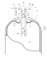
図1に示すように、ガス容器1は、全体として密閉円筒状の容器本体2と、容器本体2の長手方向の一端部または両端部に取り付けられた口金3と、を具備している。容器本体2の内部は、各種のガスを貯留する貯留空間5となっている。ガス容器1は、常圧のガスを充填することもできるし、常圧に比して圧力が高められたガスを充填することもできる。すなわち、本発明のガス容器1は、高圧ガス容器として機能することができる。
<First Embodiment>
As shown in FIG. 1, the
例えば、燃料電池システムでは、高圧の状態で用意された燃料ガスを減圧して、燃料電池の発電に供している。本発明のガス容器1は、高圧の燃料ガスを貯留するのに適用することができ、燃料ガスとしての水素ガスや、圧縮天然ガス(CNGガス)などを貯留することができる。ガス容器1に充填される水素の圧力としては、例えば35MPaあるいは70MPaであり、CNGガスの圧力としては、例えば20MPaである。
For example, in a fuel cell system, the fuel gas prepared in a high pressure state is decompressed and used for power generation of the fuel cell. The
容器本体2は、ガスバリア性を有する内側のライナー6(内殻)と、ライナー6の外側を覆うFRPからなるシェル7(外殻)と、の二層構造で構成されている。ライナー6は、例えば高密度ポリエチレンなどの樹脂や、アルミニウム合金などの金属により構成される。口金3は、例えばステンレスなどの金属で形成され、容器本体2の半球面状をした端壁部の中心に設けられている。口金3の開口部の内周面には、めねじ9が形成されており、ここにバルブアッセンブリ10がねじ込み接続されている。
The
バルブアッセンブリ10とは、ガス通路のほか、バルブや継手等の配管要素や、各種ガスセンサなどをハウジング31に一体的に組み込んだモジュールをいう。バルブアッセンブリ10は、外部のガス充填ライン21と貯留空間5とを接続すると共に、外部のガス放出ライン22と貯留空間5とを接続する。
The
例えば、燃料電池システム上のガス容器1は、ガス充填ライン21およびバルブアッセンブリ10を介して、貯留空間5に例えば高圧の水素ガスが充填される。また、燃料電池システム上のガス容器1は、バルブアッセンブリ10を介して、貯留空間5内の例えば水素ガスをガス放出ライン22に放出する。そして、ガス放出ライン22に設けた燃料電池に水素ガスが供給される。以下は、燃料電池用の高圧水素タンクに適用することを一例に説明する。
For example, in the
バルブアッセンブリ10は、ガス容器1の内外に亘るように設けられている。バルブアッセンブリ10は、各種のバルブ(46,51,52,62,63,64,74)や各種のガス通路(41〜44)を構成したハウジング31(バルブボデー)を有している。ハウジング31のネック部の外周面には、口金3のめねじ9に螺合するおねじ32が形成されており、このねじ部分を介してバルブアッセンブリ10を口金3にねじ込み接続することができる。ねじ込み接続された状態では、ハウジング31と口金3との間は、図示省略した複数のシール部材により気密にシールされる。
The
ハウジング31内には、ガス容器1の内部と外部とを連通する通路として、貯留空間5とガス充填ライン21とを連通する充填通路41と、貯留空間5とガス放出ライン22とを連通する放出通路42と、充填通路41および放出通路42とは独立したリリーフ通路43と、が設けられている。また、ハウジング31内には、充填通路41と放出通路42との間を接続する連通路44が設けられている。
In the
リリーフ通路43は、その一端がハウジング31のヘッド部において外部に開口し、その他端が貯留空間5内で開口している。リリーフ通路43には、ガス容器1内のガスが所定圧以上になっときに作動して開弁するリリーフ弁46が設けられている。
One end of the
リリーフ弁46は、ガス容器1内のガスの圧力が最低作動圧力(所定圧)に達したときに作動するものであり、例えば、ばね式(機械的)のタイプのものや、温度の上昇により溶けて圧力を完全に開放する溶栓弁などで構成されている。このような構成により、貯留空間5内が異常に高圧になったときにリリーフ弁46が開弁するため、貯留空間5内のガスをリリーフ通路43から外部に放出することができ、ガス容器1の損傷を回避することができる。なお、リリーフ弁46は、高温時(所定温度に達した時)に、リリーフ通路43を外部(大気)と連通するように溶ける溶栓弁であってもよい。
The
充填通路41は、その一端がガス充填ライン21に接続され、その他端が貯留空間5内で開口している。充填通路41には、ガスの逆流を阻止する逆止弁51と、逆止弁51に直列に配置された手動弁52と、が設けられている。これらの逆止弁51および手動弁52は、本発明にいう充填側弁や第1の弁を構成する。
One end of the filling
放出通路42は、その一端がガス放出ライン22(あるいはその下流の燃料電池)に接続され、その他端が貯留空間5内で開口している。放出通路42には、貯留空間5側から順に、ガス中の異物を捕捉するフィルタ61と、放出通路42を電気的に開閉可能な遮断弁62と、放出通路42をマニュアル操作により開閉可能な手動弁63と、ガスの圧力を減圧することにより調整する調圧弁64と、が設けられている。これらの遮断弁62および手動弁63は、本発明にいう放出側弁を構成する。
The
ここで、本明細書において、充填通路41における下流側とは、ガス充填ライン21から貯留空間5にガスを充填する際に、充填通路41でのガス流れ方向から見て下流側であることを意味する。したがって、逆止弁51は、手動弁52の上流側(一次側)に位置している。これをガス容器1との関係で換言すれば、逆止弁51から見てその下流側がガス容器1の内部側に相当し、その上流側がガス容器1の外部側に相当する。
Here, in this specification, the downstream side in the filling
同様に、放出通路42における下流側とは、貯留空間5からガス放出ライン22にガスを放出する際に、放出通路42でのガス流れ方向から見て下流側であることを意味する。したがって、放出通路42には、その上流側から順に、フィルタ61、遮断弁62、手動弁63、および調圧弁64が配置されている。これをガス容器1との関係で換言すれば、遮断弁62から見てその上流側がガス容器1の内部側に相当し、その上流側がガス容器1の外部側に相当する。
Similarly, the downstream side in the
バルブアッセンブリ10のバルブなどの各構成要素について説明する。
逆止弁51は、ガスがガス充填ライン21から充填通路41に供給された場合に、ガスが充填通路41の下流側に流れることを許容する。一方、逆止弁51は、ガス容器1内のガスが充填通路41の上流側に流れようとする場合には、そのガス圧により充填通路41を遮断して、ガスの逆流を阻止する。
Each component such as a valve of the
The
手動弁52は、逆止弁51の下流側に位置しており、ユーザによりマニュアル操作される操作部が容器本体2の外側に位置している。なお、回路図として示しているが、この操作部は、実際にはハウジング31の外壁面から外側に突出して位置している。ユーザが操作部を操作して手動弁52を閉じると、充填通路41が遮断される。なお、手動弁52に代えて、この弁を電磁弁などの電気的駆動弁で構成してもよい。また、手動弁52を省略してもよい。
The
フィルタ61は、ガス中の対象とする異物の大きさに対応したろ過度を有するフィルタエレメントを具備している。異物としては、塵埃のほか、コンタミや油分などが挙げられる。フィルタ61によりガス中の異物を取り除くことができるため、ガス放出ライン22に清浄なガスを放出することができる。また、フィルタ61が放出通路42の最も上流側に設けられているため、その下流側の遮断弁62、手動弁63および調圧弁64の各弁体や各弁座への異物の付着が防止される。
The
遮断弁62は、ガス容器1の元弁として機能するものであり、例えば容器本体2の内側に位置している。遮断弁62は、図示省略した制御装置に接続されており、制御装置からの出力信号によって開閉制御される。この種の遮断弁62は、例えばソレノイドによって駆動される電磁弁、モータによって駆動される電動弁、または圧電素子や磁歪素子などの電気・磁気力によって駆動される弁、などの電気的駆動弁により構成されている。
The shut-off
例えば、電磁弁で構成された遮断弁62は、いずれも図示省略したが、駆動源となるソレノイドと、ソレノイドの駆動により進退する弁棒と、弁棒が離接する弁座と、を具備する。そして、ソレノイドの励磁により弁棒が弁座に当接すると、放出通路42は遮断される。一方、ソレノイドの消磁により弁棒が弁座から離間すると、放出通路42は連通される。
For example, the shut-off
手動弁63は、ユーザによりマニュアル操作される操作部が容器本体2の外側に位置している。なお、回路図として示しているが、この操作部は、実際にはハウジング31の外壁面から外側に突出して位置している。ユーザが操作部を操作して手動弁63を閉じると、放出通路42が遮断される。なお、手動弁63に代えて、この弁を電磁弁などの電気的駆動弁で構成してもよい。また、手動弁63を省略してもよい。
As for the
調圧弁64(レギュレータ)は、放出通路42を流れるガスを所定圧に減圧する。調圧弁64は、直動式およびパイロット式のいずれの作動方式で構成してもよい。また、調圧弁64は、機械式に圧力を制御する構成でもよいし、例えば電空レギュレータとして構成してもよい。調圧弁64は、容器本体2の外側に位置しており、その開弁特性を調整するための操作部がハウジング31の外壁面から外側に突出して位置している。このため、調圧弁64の開弁特性を作業性良く調整することが可能となっている。
The pressure regulating valve 64 (regulator) reduces the gas flowing through the
連通路44は、その一端が充填通路41における手動弁52の下流側(または逆止め弁51から見て下流側)に接続され、その他端が放出通路42における遮断弁62の下流側(または手動弁63から見て下流側)であって且つ調圧弁64の上流側に接続されている。すなわち、連通路44と充填通路41との接続合流点71は、手動弁52の下流側に設けられ、連通路44と放出通路42との接続合流点72は、遮断弁62と調圧弁64との間に設けられている。連通路44には、これを開閉可能な遮断弁74が設けられている。
One end of the
遮断弁74(連通遮断機構)は、放出通路42の遮断弁62と同様に電気的駆動弁で構成することもできるし、放出通路42の手動弁63と同様に構成することもできる。本実施形態の遮断弁74は、手動弁で構成されており、マニュアル操作により連通路44を開閉するための手動操作部を有している。手動操作部は、弁体に連結されており、手動操作部の操作により弁体が弁座に対して離接する。この種の手動操作部は、例えば、回転操作する円形状のハンドルのほか、レバーや、プッシュプル操作方式のボタンにより構成することができる。
The shut-off valve 74 (communication shut-off mechanism) can be configured as an electrically driven valve in the same manner as the shut-off
手動操作部は、容器本体2の外側に位置し、しかもハウジング31の外壁面から外側に突出して位置するように設けられている。このため、ユーザは、バルブアッセンブリ10を口金3から取り外すことなく、手動操作部に簡単にアクセスすることができる。ユーザが手動操作部を操作して遮断弁74を開いた状態にすると、充填通路41と放出通路42との連通が許容される。一方、遮断弁74を閉じた状態にすると、充填通路41と放出通路42との連通が遮断される。後述するように、遮断弁74は、常時は閉弁しており、主として遮断弁62の故障時等に開弁される。
The manual operation unit is provided on the outside of the
遮断弁74は、各種の機能のものを適用することができる。例えば、遮断弁74のタイプとしては、仕切り弁、玉形弁、バタフライ弁、ボール弁などが挙げられる。また、例えば、充填通路41と放出通路42とがハウジング31内で直交する場合など平行でない場合には、アングル弁タイプやY形弁タイプの玉形弁で遮断弁74を構成すればよい。
The
ここで、本実施形態のバルブアッセンブリ10の作用について説明する。
ガス容器1へのガスの充填時は、手動弁52を開いた状態で、ガス充填ライン21から充填通路41を介して貯留空間5にガスを導入する。このとき、連通路44上の遮断弁74は閉じられており、充填通路41を流れるガスが、連通路44を介して放出通路42に流れ込まないようになっている。ガスの充填完了後には、手動弁52を閉じた状態とする。なお、充填通路41には逆止弁51が設けられているため、ガスの充填完了後に手動弁52を閉じなくとも、充填通路41外へのガスの流出を阻止することができる。
Here, the operation of the
When the gas is filled into the
ガス容器1からガスを放出する際には、遮断弁62および手動弁63を開いた状態とする。遮断弁62の開弁作動は、例えば燃料電池システムにおける発電要求に基づいて、図示省略した制御装置により電気制御的になされる。手動弁63は、ガス放出の前から予め開弁した状態であってもよい。遮断弁62および手動弁63を開弁状態とすることで、貯留空間5内のガスは、放出通路42を流れ、調圧弁64により減圧されてガス放出ライン22へと流出する。このとき、連通路44上の遮断弁74は閉じられており、放出通路42を流れるガスは、連通路44を介して充填通路41に流れ込まないようになっている。
When the gas is discharged from the
ところが、遮断弁62が固着して開かなくなったり、制御回路が断線して遮断弁62を開けなかったりするなど、故障により遮断弁62が開かない場合がある。このような場合、遮断弁62の点検や交換などのため、バルブアッセンブリ10を口金3から取り外す必要がある。この取外し作業は、ガス容器1にガスが充填されたままであると煩雑となるため、ガス容器1からガスを放出する必要がある。しかしこの場合、故障等により遮断弁62が開かないため、放出通路42のフィルタ61や遮断弁62にガスを通して、放出通路42の下流側へと放出することができない。
However, the shut-off
そこで本実施形態では、ガスを放出通路42から放出するために、連通路44上の遮断弁74を開いて、充填通路41と放出通路42とを連通させるようにしている。こうすることで、図においてガスの流れを破線の矢印で示すように、貯留空間5内のガスは、充填通路41を流れて連通路44に流れ込み、連通路44から放出通路42の下流側へと流れる。
Therefore, in the present embodiment, in order to release the gas from the
これにより、故障等により遮断弁62が開かない場合であっても、充填通路41を有効に利用して、ガス容器1内のガスを放出通路42から適切に放出させることができる。また、そのガス放出の際に、放出通路42を流れるガスは、調圧弁64を通過する。これにより、ガスを減圧して、ガス容器1外部に放出することができる。なお、この故障時に放出されるガスを、例えば燃料電池システムでの燃料電池の発電に利用してもよい。また、故障時に放出されるガスを、希釈ガス(空気または不活性ガス)によって濃度を低減してから大気放出してもよいし、触媒上で酸化反応させることによって濃度を低減してもよい。
Thereby, even when the
また上記の不具合とは逆に、遮断弁62が固着して閉じなくなったり、制御回路が断線して遮断弁62を閉じられなくなったりするなど、故障等により遮断弁62が閉じない場合がある。このような場合、遮断弁62の下流側の手動弁63を閉じることで、貯留空間5からガス放出ライン22へのガスの流出を阻止することができる。もっとも、この不具合の際には、連通路44上の遮断弁74を閉じておく必要があることは言うまでもない。また上述のように、ガス容器1内の異常高圧時には、開弁されるリリーフ弁46によってリリーフ通路43からガス容器1内のガスを放出することができ、ガス容器1の損傷を回避することができる。
Contrary to the above problems, the shut-off
なお、上記の説明では、遮断弁74を手動弁で構成したが、その操作方式を代えて、例えば遮断弁74を足踏弁で構成してもよい。すなわち、手動弁や足踏弁等の人力操作弁で遮断弁74を構成してもよい。この点、手動弁52および手動弁63も同様である。
In the above description, the shut-off
<第2実施形態>
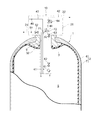
次に、図2を参照して、第2実施形態に係るバルブアッセンブリ10について相違点を中心に説明する。第1実施形態との相違点は、放出通路42に圧力センサ81および温度センサ91を設けたことである。
<Second Embodiment>
Next, with reference to FIG. 2, the
圧力センサ81は、放出通路42と連通路44との接続合流点72の下流側であって調圧弁64の上流側に設けられている。圧力センサ81が調圧弁64の一次側に位置しているため、圧力センサ81により貯留空間5のガスの圧力を検出することができる。圧力センサ81は、放出通路42から側方に分岐するように設けられた通路82に、取り付けられるように設けられている。圧力センサ81と通路82との取付け部分は、図示省略したシール部材によりシールされている。
The
同様に、温度センサ91は、放出通路42と連通路44との接続合流点72の下流側であって調圧弁64の上流側に設けられている。温度センサ91により、貯留空間5のガスの温度を検出することができる。温度センサ91は、放出通路42から側方に分岐するように設けられた通路92に、取り付けられるように設けられている。温度センサ91と通路92との取付け部分は、図示省略したシール部材によりシールされている。
Similarly, the temperature sensor 91 is provided downstream of the
本実施形態によれば、圧力センサ81および温度センサ91により、ガス容器1内のガスの充填量を算出することができる。また、仮に圧力センサ81からガス漏れが生じたり、あるいは圧力センサ81と通路82との取付け部分(シール部分)からガス漏れが生じたりしても、遮断弁62を閉じることで、そのガス漏れを阻止することができる。同様に、仮に温度センサ91からガス漏れが生じたり、あるいは温度センサ91と通路92との取付け部分からガス漏れが生じたりしても、遮断弁62を閉じることで、そのガス漏れを阻止することができる。したがって、圧力センサ81および温度センサ91のシール構造を簡素化することができる。
According to the present embodiment, the filling amount of the gas in the
なお、圧力センサ81と温度センサ91との位置関係は、逆であってもよい。また、圧力センサ81および温度センサ91は、遮断弁62の下流側の位置であればよく、例えば放出通路42と連通路44との接続合流点72よりも上流側であってもよい。また、圧力センサ81および温度センサ91の一方を省略してもよい。
The positional relationship between the
<第3実施形態>
次に、図3を参照して、第3実施形態に係るバルブアッセンブリ10について相違点を中心に説明する。第1実施形態との相違点は、充填通路41に逆止弁101(充填側弁)を追加したことである。
<Third Embodiment>
Next, with reference to FIG. 3, the
すなわち、充填通路41には、同様の機能を有する二つの逆止弁51,101が直列に配置されている。このような構成とすることで、仮に一方の逆止弁(51または101)が故障等して、逆流となるガスの流出を阻止できなくなったとしても、もう一方の逆止弁(101または51)でガスの逆流を阻止することができる。なお、上流側の逆止弁51に比べて下流側の逆止弁101の最低作動圧力を小さく設定しておくことが好ましい。また、充填通路41に設ける逆止弁は二以上の複数であってもよい。
That is, two
<第4実施形態>
次に、図4を参照して、第4実施形態に係るバルブアッセンブリ10について相違点を中心に説明する。第1実施形態との相違点は、リリーフ通路43を充填通路41に分岐接続したことである。
<Fourth embodiment>
Next, with reference to FIG. 4, the
リリーフ通路43は、その一端がハウジング31の外部に開口し、その他端が充填通路41に接続されている。リリーフ通路43と充填通路41との分岐接続点は、逆止弁51の下流側に位置している。このような構成とすることで、第1〜第3実施形態に比べて、各通路(41〜44)における各種弁(51,52,62,63,64,74)の配置の自由度を高めることができると共に、バルブアッセンブリ10全体のサイズを小さくし得る。なお、図4では、充填通路41の手動弁52および放出通路42の手動弁63を省略した。
The
<第5実施形態>
次に、図5を参照して、第5実施形態に係るバルブアッセンブリ10について相違点を中心に説明する。第1実施形態との相違点は、リリーフ通路43と放出通路42とを連通路44で接続し、それに伴い充填通路41と放出通路42とを独立させたことである。
<Fifth Embodiment>
Next, the
連通路44の一端は、リリーフ弁46(第1の弁)よりも上流側、すなわちリリーフ弁46から見て貯留空間5側のリリーフ通路43の部分に接続している。連通路44の他端は、上記同様に、放出通路42における遮断弁62の下流側であって且つ調圧弁64の上流側に接続されている。連通路44には、上記同様に、これを開閉可能な遮断弁74(連通遮断機構)が設けられている。
One end of the
本実施形態によれば、故障等により遮断弁62が開かなくなっても、連通路44上の遮断弁74を開いて、リリーフ通路43と放出通路42とを連通させることができる。こうすることで、図においてガスの流れを破線の矢印で示すように、貯留空間5内のガスは、リリーフ通路43を流れて連通路44に流れ込み、連通路44から放出通路42の下流側へと流れる。このように、故障等により遮断弁62が開かない場合に、本実施形態のようにリリーフ通路43を有効に利用しても、ガス容器1内のガスを放出通路42から適切に放出させることができる。
According to this embodiment, even if the
<他の実施形態>
以上の第1〜第5実施形態の説明では、遮断弁74により充填通路41(またはリリーフ通路43)と放出通路42との連通を遮断するようにしたが、この連通を許容しつつ且つ遮断可能な連通遮断機構を構成することもできる。
<Other embodiments>
In the above description of the first to fifth embodiments, the communication between the filling passage 41 (or the relief passage 43) and the
例えば、図1を参照して説明するに、連通遮断機構は、充填通路41における接続合流点71の上流側および下流側に設けた図示省略した二つの遮断弁と、放出通路42における接続合流点72の上流側および下流側に設けた図示省略した二つの遮断弁と、で構成することができる。放出通路42における接続合流点72の上流側の遮断弁については、上記の遮断弁62を適用することができる。この四つの遮断弁をガスの充填時およびガスの放出時に加えて、遮断弁62が開かない場合のガスの放出時に適宜開閉すれば、上記したバルブアッセンブリ10の仕様を達成することができる。
For example, referring to FIG. 1, the communication cutoff mechanism includes two cutoff valves (not shown) provided upstream and downstream of the
上記した本発明のバルブアッセンブリ10を備えたガス容器1は、燃料電池システムを搭載した車両などに用いるのに好適である。また、車両以外の航空機や船舶など、ガス容器を動力源として用いる輸送機関にも、本発明のガス容器1を好適に適用することができる。
The
1:ガス容器、10:バルブアッセンブリ、41:充填通路、42:放出通路、43:リリーフ通路、44:連通路、46:リリーフ弁、51:逆止弁(充填側弁)、52:手動弁(充填側弁)、61:フィルタ、62:遮断弁(放出側弁)、63:手動弁(放出側弁)、64:調圧弁、74:遮断弁(連通遮断機構)、81:圧力センサ、91:温度センサ、101:逆止弁(充填側弁) 1: gas container, 10: valve assembly, 41: filling passage, 42: discharge passage, 43: relief passage, 44: communication passage, 46: relief valve, 51: check valve (filling side valve), 52: manual valve (Fill valve), 61: filter, 62: shutoff valve (release valve), 63: manual valve (release valve), 64: pressure regulating valve, 74: shutoff valve (communication shutoff mechanism), 81: pressure sensor, 91: Temperature sensor, 101: Check valve (filling side valve)
Claims (25)
前記充填通路に設けられ、これを遮断可能な充填側弁と、
前記放出通路に設けられ、これを遮断可能な放出側弁と、
前記放出側弁の下流側と前記充填側弁の下流側との間を接続する連通路と、
前記連通路を開閉する連通遮断機構と、を備え、
前記連通遮断機構が前記連通路を開くことにより、前記ガス容器内のガスが、前記充填通路を逆流し、前記連通路を介して前記放出通路へと流れるようにした、ガス容器用バルブアッセンブリ。 A gas container valve assembly provided in a gas container, the gas container having a filling passage for filling gas and a discharge passage for discharging gas as a passage communicating the inside and the outside of the gas container Valve assembly
A filling side valve provided in the filling passage and capable of shutting it off;
A discharge-side valve provided in the discharge passage and capable of shutting it off;
A communication path connecting the downstream side of the discharge side valve and the downstream side of the filling side valve;
A communication blocking mechanism for opening and closing the communication path ,
A gas container valve assembly in which the communication blocking mechanism opens the communication passage so that the gas in the gas container flows backward in the filling passage and flows to the discharge passage through the communication passage .
前記手動操作部は、前記ガス容器外に配置されている請求項3に記載のガス容器用バルブアッセンブリ。 The shut-off valve is a manual valve having a manual operation unit for opening and closing the communication path,
The valve assembly for a gas container according to claim 3, wherein the manual operation unit is disposed outside the gas container.
前記複数の充填側弁には、前記充填通路に直列に配置された逆止弁が含まれる請求項1ないし7のいずれか一項に記載のガス容器用バルブアッセンブリ。 A plurality of the filling side valves are provided,
The valve assembly for a gas container according to any one of claims 1 to 7, wherein the plurality of filling side valves include a check valve arranged in series in the filling passage.
前記複数の放出側弁には、電気的駆動弁と、この下流側に位置する人力操作弁と、が含まれる請求項1ないし9のいずれか一項に記載のガス容器用バルブアッセンブリ。 A plurality of the discharge side valves are provided,
The gas container valve assembly according to any one of claims 1 to 9, wherein the plurality of discharge side valves include an electrically driven valve and a manually operated valve located on the downstream side.
前記リリーフ弁が設けられ、当該リリーフ弁の開弁により前記ガス容器の内部と外部とを連通するリリーフ通路と、
を更に有している請求項1ないし13のいずれか一項に記載のガス容器用バルブアッセンブリ。 A relief valve that is opened when the gas in the gas container reaches a predetermined pressure or higher;
A relief passage provided with the relief valve, wherein the relief valve communicates with the outside and inside of the gas container by opening the relief valve;
The valve assembly for a gas container according to any one of claims 1 to 13 , further comprising:
前記充填側弁は、前記リリーフ通路と前記充填通路との分岐接続点の上流側に位置している請求項14に記載のガス容器用バルブアッセンブリ。 The relief passage is a passage branched and connected to the filling passage,
The valve assembly for a gas container according to claim 14 , wherein the filling side valve is located upstream of a branch connection point between the relief passage and the filling passage.
前記放出通路は、前記ガス容器の内部と前記燃料電池システムにおける燃料電池に前記ガスを放出するためのガス放出ラインとを連通する、請求項1ないし16のいずれか一項に記載のガス容器用バルブアッセンブリ。17. The gas container according to claim 1, wherein the discharge passage communicates the inside of the gas container and a gas discharge line for discharging the gas to a fuel cell in the fuel cell system. Valve assembly.
前記ガス容器の内部と外部とを連通するガスの放出通路と、
前記ガス容器の内部と外部とを連通し、前記放出通路とは異なる第1のガス通路と、
前記放出通路に設けられ、これを遮断可能な放出側弁と、
前記第1のガス通路に設けられ、これを遮断可能な第1の弁と、
前記放出側弁から見て前記ガス容器の外部側の前記放出通路の部分と、前記第1の弁から見て前記ガス容器の内部側の前記第1のガス通路の部分との間を接続する連通路と、
前記連通路を開閉する連通遮断機構と、を備え、
前記連通遮断機構が前記連通路を開くことにより、前記ガス容器内のガスが、前記第1のガス通路、前記連通路、及び前記放出通路の順に流れるようにした、ガス容器用バルブアッセンブリ。 A valve assembly for a gas container provided in the gas container,
A gas discharge passage communicating the inside and the outside of the gas container;
A first gas passage that communicates the inside and the outside of the gas container and is different from the discharge passage;
A discharge-side valve provided in the discharge passage and capable of shutting it off;
A first valve provided in the first gas passage and capable of shutting it off;
A connection is made between a portion of the discharge passage on the outer side of the gas container as viewed from the discharge valve and a portion of the first gas passage on the inner side of the gas container as viewed from the first valve. A communication path,
A communication blocking mechanism for opening and closing the communication path ,
A gas container valve assembly in which the gas in the gas container flows in the order of the first gas path, the communication path, and the discharge path by the communication blocking mechanism opening the communication path .
当該ガス容器用バルブアッセンブリは、前記口金に設けられている、請求項1ないし23のいずれか一項に記載のガス容器用バルブアッセンブリ。The gas container valve assembly according to any one of claims 1 to 23, wherein the gas container valve assembly is provided in the base.
Priority Applications (8)
| Application Number | Priority Date | Filing Date | Title |
|---|---|---|---|
| JP2005056071A JP4496477B2 (en) | 2005-03-01 | 2005-03-01 | Valve assembly for gas container |
| PCT/JP2006/303516 WO2006093060A1 (en) | 2005-03-01 | 2006-02-20 | Valve assembly for gas container |
| CA 2598624 CA2598624C (en) | 2005-03-01 | 2006-02-20 | Valve assembly for gas container |
| CN2006800069759A CN101133281B (en) | 2005-03-01 | 2006-02-20 | Valve assembly for gas container |
| RU2007135747A RU2355943C1 (en) | 2005-03-01 | 2006-02-20 | Valve assembly in gas storage tank |
| EP20060714655 EP1855048B1 (en) | 2005-03-01 | 2006-02-20 | Valve assembly for gas container |
| US11/884,129 US8573253B2 (en) | 2005-03-01 | 2006-02-20 | Valve assembly for gas container |
| KR1020077020048A KR100903663B1 (en) | 2005-03-01 | 2006-02-20 | Valve assembly for gas container |
Applications Claiming Priority (1)
| Application Number | Priority Date | Filing Date | Title |
|---|---|---|---|
| JP2005056071A JP4496477B2 (en) | 2005-03-01 | 2005-03-01 | Valve assembly for gas container |
Publications (3)
| Publication Number | Publication Date |
|---|---|
| JP2006242225A JP2006242225A (en) | 2006-09-14 |
| JP2006242225A5 JP2006242225A5 (en) | 2007-09-13 |
| JP4496477B2 true JP4496477B2 (en) | 2010-07-07 |
Family
ID=36941091
Family Applications (1)
| Application Number | Title | Priority Date | Filing Date |
|---|---|---|---|
| JP2005056071A Active JP4496477B2 (en) | 2005-03-01 | 2005-03-01 | Valve assembly for gas container |
Country Status (8)
| Country | Link |
|---|---|
| US (1) | US8573253B2 (en) |
| EP (1) | EP1855048B1 (en) |
| JP (1) | JP4496477B2 (en) |
| KR (1) | KR100903663B1 (en) |
| CN (1) | CN101133281B (en) |
| CA (1) | CA2598624C (en) |
| RU (1) | RU2355943C1 (en) |
| WO (1) | WO2006093060A1 (en) |
Families Citing this family (47)
| Publication number | Priority date | Publication date | Assignee | Title |
|---|---|---|---|---|
| JP4714125B2 (en) * | 2006-11-16 | 2011-06-29 | 本田技研工業株式会社 | Gas fuel piping equipment |
| WO2009079218A2 (en) | 2007-12-06 | 2009-06-25 | L'air Liquide Societe Anonyme Pour L'etude Et L'exploitation Des Procedes Georges Claude | Integrated valve regulator assembly and system for the controlled storage and dispensing of a hazardous material |
| JP5239376B2 (en) * | 2008-02-14 | 2013-07-17 | トヨタ自動車株式会社 | Fuel cell system |
| FR2927979A1 (en) * | 2008-02-21 | 2009-08-28 | Air Liquide | DEVICE FOR FILLING AND DISPENSING GAS AND FILLING METHOD. |
| US8104500B2 (en) * | 2008-04-18 | 2012-01-31 | Texas Institute Of Science, Inc. | Acoustic liquid level detection |
| FR2930619A1 (en) * | 2008-04-24 | 2009-10-30 | Air Liquide | PRESSURIZED GAS RECEIVER DEVICE, DISPENSER-RECEIVER DEVICE ASSEMBLY AND CORRESPONDING POWER SUPPLY SYSTEM |
| FR2931223B1 (en) | 2008-05-16 | 2010-08-20 | Air Liquide | PRESSURIZED GAS DISPENSING DEVICE, ASSEMBLY COMPRISING SUCH A DEVICE AND CONTROL DEVICE, CONTAINER HAVING SUCH A DISPENSING DEVICE |
| JP5381104B2 (en) * | 2009-01-05 | 2014-01-08 | トヨタ自動車株式会社 | Valve assembly for gas container |
| PT2389533E (en) * | 2009-01-26 | 2013-02-05 | Cavagna Group Spa | A valve unit for pressure vessels |
| JP5409036B2 (en) * | 2009-02-16 | 2014-02-05 | トヨタ自動車株式会社 | Valve device for high-pressure tank for vehicles |
| JP2010245004A (en) * | 2009-04-10 | 2010-10-28 | Honda Motor Co Ltd | Fuel-filling and supplying system |
| JP5386249B2 (en) | 2009-07-03 | 2014-01-15 | トヨタ自動車株式会社 | Valve device for high-pressure tank for vehicles |
| JP5333145B2 (en) * | 2009-10-14 | 2013-11-06 | トヨタ自動車株式会社 | Valve device for high-pressure tank for vehicles |
| JP5115565B2 (en) * | 2010-02-15 | 2013-01-09 | トヨタ自動車株式会社 | vehicle |
| JP5466033B2 (en) * | 2010-02-15 | 2014-04-09 | トヨタ自動車株式会社 | High pressure tank pressure release valve |
| JP2011179528A (en) * | 2010-02-26 | 2011-09-15 | Kawasaki Heavy Ind Ltd | Tank internal pressure measurement circuit and tank device provided therewith |
| FR2974883B1 (en) * | 2011-05-04 | 2014-05-09 | Michelin Soc Tech | VALVE MOUNTED ON A TANK CONTAINING A HIGH PRESSURE GAS |
| JP6007317B2 (en) * | 2012-06-04 | 2016-10-12 | ヨンド・アイエヌデー・カンパニー・リミテッド | Valve assembly for fluid control |
| DE102012019908A1 (en) * | 2012-10-11 | 2014-04-17 | Linde Aktiengesellschaft | Method and device for at least partial degassing of a vessel containing a fluid |
| EP2927549B1 (en) * | 2012-11-05 | 2016-06-29 | Magna Steyr Fahrzeugtechnik AG & Co KG | Pressure storage valve unit for a pressure storage container |
| EP2728228B1 (en) * | 2012-11-05 | 2015-06-17 | Magna Steyr Fahrzeugtechnik AG & Co KG | Sealing valve for a pressure storage container |
| CN104006285A (en) | 2013-02-22 | 2014-08-27 | 西门子公司 | Drainage system for gas turbine |
| US8910651B2 (en) * | 2013-03-13 | 2014-12-16 | GM Global Technology Operations LLC | Thermal pressure relief devices and related systems and methods |
| KR101497420B1 (en) * | 2013-07-05 | 2015-03-03 | 삼성중공업 주식회사 | LNG transportation Apparatus for reducing Boil-Off Gas |
| US20150059895A1 (en) * | 2013-08-30 | 2015-03-05 | dHybrid Systems, LLC | Vehicle fueling manifold assembly |
| ITBS20130164A1 (en) * | 2013-11-13 | 2015-05-14 | Omb Saleri S P A | VALVE FOR METHANE IN SYSTEMS FOR AUTOTRUPTION WITH A THERMAL SAFETY DEVICE |
| NL2015258A (en) * | 2014-08-03 | 2016-07-07 | Protochips Inc | Method for safe control of gas delivery to an electron microscope sample holder. |
| EP3324086B1 (en) * | 2015-07-15 | 2019-09-11 | Nissan Motor Co., Ltd. | Valve device |
| GB201520374D0 (en) | 2015-11-19 | 2016-01-06 | Moog Controls Ltd | A method for releasing a fluid from a pressure vessel assembly |
| US10696155B2 (en) | 2016-04-01 | 2020-06-30 | Agility Fuel Systems Llc | Vehicle fluid handling systems |
| DE102016008107A1 (en) * | 2016-07-01 | 2018-01-04 | Daimler Ag | tank valve |
| DE102017201045A1 (en) * | 2017-01-23 | 2018-07-26 | Bayerische Motoren Werke Aktiengesellschaft | Pressure vessel system for a motor vehicle |
| JP6878040B2 (en) * | 2017-02-20 | 2021-05-26 | 株式会社Soken | Valve device |
| FR3067094B1 (en) * | 2017-06-01 | 2020-08-14 | L'air Liquide Sa Pour L'etude Et L'exploitation Des Procedes Georges Claude | TAP, STORAGE AND FILLING STATION |
| FR3067095B1 (en) * | 2017-06-01 | 2020-08-14 | L'air Liquide Sa Pour L'etude Et L'exploitation Des Procedes Georges Claude | TAP, STORAGE AND FILLING STATION |
| DE102017213521A1 (en) * | 2017-08-03 | 2019-02-07 | Bayerische Motoren Werke Aktiengesellschaft | Valve device for a storage tank |
| DE102017213524A1 (en) * | 2017-08-03 | 2019-02-07 | Bayerische Motoren Werke Aktiengesellschaft | Valve device for a pressure vessel of a pressure vessel system with a plurality of pressure vessels |
| JP6515982B1 (en) * | 2017-11-22 | 2019-05-22 | 横浜ゴム株式会社 | Aircraft water tank and method of manufacturing the same |
| US11440399B2 (en) | 2019-03-22 | 2022-09-13 | Agility Fuel Systems Llc | Fuel system mountable to a vehicle frame |
| JP7257856B2 (en) * | 2019-04-05 | 2023-04-14 | キヤノン株式会社 | recording device |
| US20200347992A1 (en) | 2019-05-02 | 2020-11-05 | Agility Fuel Systems Llc | Polymeric liner based gas cylinder with reduced permeability |
| WO2020250284A1 (en) * | 2019-06-10 | 2020-12-17 | 合同会社パッチドコニックス | Fluid supply device |
| TWI706103B (en) * | 2019-08-05 | 2020-10-01 | 古豐愿 | Vacuum supply gas cylinder |
| DE102019212037A1 (en) * | 2019-08-12 | 2021-02-18 | Robert Bosch Gmbh | System for pressure relief of a pressure vessel |
| CN112555679B (en) | 2019-09-26 | 2022-02-25 | 未势能源科技有限公司 | Pressure vessel and vehicle |
| DE102019128427A1 (en) * | 2019-10-22 | 2021-04-22 | Audi Ag | Valve device and gas pressure accumulator |
| DE202021004175U1 (en) * | 2020-04-24 | 2022-12-19 | Youon Technology Co., Ltd. | Hydrogen storage and hydrogen storage system |
Citations (7)
| Publication number | Priority date | Publication date | Assignee | Title |
|---|---|---|---|---|
| US4583372A (en) * | 1985-01-30 | 1986-04-22 | At&T Technologies, Inc. | Methods of and apparatus for storing and delivering a fluid |
| JPH08159397A (en) * | 1994-06-24 | 1996-06-21 | Neriki:Kk | Valve device for gas cylinder |
| JPH11218297A (en) * | 1997-11-14 | 1999-08-10 | Air Prod And Chem Inc | Gas control device and gas supplying method |
| JP2943980B2 (en) * | 1997-07-24 | 1999-08-30 | 本田技研工業株式会社 | Gas fuel piping system |
| JP2003166700A (en) * | 2001-11-30 | 2003-06-13 | Nippon Sanso Corp | Valve for liquefied petroleum cylinder with decompression function |
| WO2003054441A1 (en) * | 2001-12-20 | 2003-07-03 | L'air Liquide Societe Anonyme A Directoire Et Conseil De Surveillance Pour L'etude Et L'exploitation Des Procedes Georges Claude | Device for storing and mixing two gases |
| JP2005048918A (en) * | 2003-07-31 | 2005-02-24 | Toyota Motor Corp | Tank |
Family Cites Families (12)
| Publication number | Priority date | Publication date | Assignee | Title |
|---|---|---|---|---|
| US3307597A (en) * | 1964-09-16 | 1967-03-07 | Voit Rubber Corp | First stage pressure regulators mounted within air cylinder plug |
| US4006205A (en) * | 1975-03-17 | 1977-02-01 | Etter Berwyn E | Means for applying additives to industrial gas |
| US5197710A (en) | 1991-05-30 | 1993-03-30 | Lloyd G. Wass | Crash proof solenoid controlled valve for natural gas powered vehicles |
| US5193580A (en) | 1991-05-30 | 1993-03-16 | Wass Lloyd G | Crash proof solenoid controlled valve with manual override valve |
| DE69300301T2 (en) * | 1992-09-09 | 1996-04-04 | Neriki Kk | Valve arrangement for gas containers. |
| AU691270B2 (en) * | 1994-06-24 | 1998-05-14 | Kabushiki Kaisha Neriki | Valve assembly for gas cylinder |
| US6041762A (en) | 1996-08-16 | 2000-03-28 | Impco Technologies, Inc. | Control module for natural gas fuel supply for a vehicle |
| US7013916B1 (en) * | 1997-11-14 | 2006-03-21 | Air Products And Chemicals, Inc. | Sub-atmospheric gas delivery method and apparatus |
| US6766829B2 (en) * | 2000-02-18 | 2004-07-27 | Kabushiki Kaisha Neriki | Valve assembly for gas cylinder |
| CA2312186A1 (en) | 2000-06-23 | 2001-12-23 | Erick Girouard | Crashproof instant-on tank valve |
| JP2002115798A (en) * | 2000-10-06 | 2002-04-19 | Neriki:Kk | Valve device |
| JP4774634B2 (en) | 2001-06-15 | 2011-09-14 | トヨタ自動車株式会社 | Gas storage system |
-
2005
- 2005-03-01 JP JP2005056071A patent/JP4496477B2/en active Active
-
2006
- 2006-02-20 CN CN2006800069759A patent/CN101133281B/en active Active
- 2006-02-20 EP EP20060714655 patent/EP1855048B1/en active Active
- 2006-02-20 KR KR1020077020048A patent/KR100903663B1/en active IP Right Grant
- 2006-02-20 CA CA 2598624 patent/CA2598624C/en active Active
- 2006-02-20 RU RU2007135747A patent/RU2355943C1/en not_active IP Right Cessation
- 2006-02-20 WO PCT/JP2006/303516 patent/WO2006093060A1/en active Application Filing
- 2006-02-20 US US11/884,129 patent/US8573253B2/en active Active
Patent Citations (7)
| Publication number | Priority date | Publication date | Assignee | Title |
|---|---|---|---|---|
| US4583372A (en) * | 1985-01-30 | 1986-04-22 | At&T Technologies, Inc. | Methods of and apparatus for storing and delivering a fluid |
| JPH08159397A (en) * | 1994-06-24 | 1996-06-21 | Neriki:Kk | Valve device for gas cylinder |
| JP2943980B2 (en) * | 1997-07-24 | 1999-08-30 | 本田技研工業株式会社 | Gas fuel piping system |
| JPH11218297A (en) * | 1997-11-14 | 1999-08-10 | Air Prod And Chem Inc | Gas control device and gas supplying method |
| JP2003166700A (en) * | 2001-11-30 | 2003-06-13 | Nippon Sanso Corp | Valve for liquefied petroleum cylinder with decompression function |
| WO2003054441A1 (en) * | 2001-12-20 | 2003-07-03 | L'air Liquide Societe Anonyme A Directoire Et Conseil De Surveillance Pour L'etude Et L'exploitation Des Procedes Georges Claude | Device for storing and mixing two gases |
| JP2005048918A (en) * | 2003-07-31 | 2005-02-24 | Toyota Motor Corp | Tank |
Also Published As
| Publication number | Publication date |
|---|---|
| EP1855048B1 (en) | 2012-03-28 |
| JP2006242225A (en) | 2006-09-14 |
| KR100903663B1 (en) | 2009-06-18 |
| CA2598624A1 (en) | 2006-09-08 |
| US8573253B2 (en) | 2013-11-05 |
| EP1855048A1 (en) | 2007-11-14 |
| KR20070099687A (en) | 2007-10-09 |
| CN101133281B (en) | 2010-04-21 |
| EP1855048A4 (en) | 2009-04-15 |
| WO2006093060A1 (en) | 2006-09-08 |
| RU2355943C1 (en) | 2009-05-20 |
| CA2598624C (en) | 2010-06-08 |
| US20080105310A1 (en) | 2008-05-08 |
| CN101133281A (en) | 2008-02-27 |
Similar Documents
| Publication | Publication Date | Title |
|---|---|---|
| JP4496477B2 (en) | Valve assembly for gas container | |
| JP6896777B2 (en) | Tank valve | |
| JP5174669B2 (en) | Tank manifold assembly | |
| US7426935B2 (en) | Method of discharging high pressure storage vessels | |
| US6691729B2 (en) | Valve assembly | |
| US8474792B2 (en) | Valve device and manually operated shutoff valve device | |
| US20220049819A1 (en) | Tank device for storing a gaseous medium | |
| WO2006129878A1 (en) | High-pressure tank | |
| JP2011012780A (en) | Valve system of high pressure tank for vehicle | |
| US20220034454A1 (en) | Tank device for storing a gaseous medium | |
| US20190041292A1 (en) | Fuel vapor processing device | |
| US8166753B2 (en) | Accumulator system and method of monitoring same | |
| JP4714125B2 (en) | Gas fuel piping equipment | |
| JP2006141122A (en) | Fuel supplying apparatus, control method of fuel supplying apparatus | |
| JP5239376B2 (en) | Fuel cell system | |
| KR102310549B1 (en) | The fuel cell system in the hydrogen supplying system and control method thereof | |
| JP2023547420A (en) | Tank device for storing gaseous media | |
| JP2007278483A (en) | Emergency shut-off valve | |
| KR20040073361A (en) | Submarine | |
| JP4923191B2 (en) | Valve device for hydrogen gas container used in fuel cell system | |
| JP2005207363A (en) | Gaseous fuel supply system | |
| WO2024100337A1 (en) | System for storing and/or transporting a natural gas in liquid state | |
| KR20240071575A (en) | Hydrogen Tank Valve having cut off and exhaust function integrated type manual valve and Hydrogen Tank System thereby | |
| JP2006052787A (en) | Container valve | |
| JP2006057773A (en) | Gas supply system |
Legal Events
| Date | Code | Title | Description |
|---|---|---|---|
| A521 | Written amendment |
Free format text: JAPANESE INTERMEDIATE CODE: A523 Effective date: 20070730 |
|
| A621 | Written request for application examination |
Free format text: JAPANESE INTERMEDIATE CODE: A621 Effective date: 20070730 |
|
| TRDD | Decision of grant or rejection written | ||
| A01 | Written decision to grant a patent or to grant a registration (utility model) |
Free format text: JAPANESE INTERMEDIATE CODE: A01 Effective date: 20100318 |
|
| A01 | Written decision to grant a patent or to grant a registration (utility model) |
Free format text: JAPANESE INTERMEDIATE CODE: A01 |
|
| A61 | First payment of annual fees (during grant procedure) |
Free format text: JAPANESE INTERMEDIATE CODE: A61 Effective date: 20100331 |
|
| FPAY | Renewal fee payment (event date is renewal date of database) |
Free format text: PAYMENT UNTIL: 20130423 Year of fee payment: 3 |
|
| R151 | Written notification of patent or utility model registration |
Ref document number: 4496477 Country of ref document: JP Free format text: JAPANESE INTERMEDIATE CODE: R151 |
|
| FPAY | Renewal fee payment (event date is renewal date of database) |
Free format text: PAYMENT UNTIL: 20140423 Year of fee payment: 4 |