JP4495866B2 - Cartridge for controlling chemical reactions - Google Patents
Cartridge for controlling chemical reactions Download PDFInfo
- Publication number
- JP4495866B2 JP4495866B2 JP2000621073A JP2000621073A JP4495866B2 JP 4495866 B2 JP4495866 B2 JP 4495866B2 JP 2000621073 A JP2000621073 A JP 2000621073A JP 2000621073 A JP2000621073 A JP 2000621073A JP 4495866 B2 JP4495866 B2 JP 4495866B2
- Authority
- JP
- Japan
- Prior art keywords
- chamber
- cartridge
- reaction chamber
- reaction
- cartridge according
- Prior art date
- Legal status (The legal status is an assumption and is not a legal conclusion. Google has not performed a legal analysis and makes no representation as to the accuracy of the status listed.)
- Expired - Lifetime
Links
Images


Classifications
-
- B—PERFORMING OPERATIONS; TRANSPORTING
- B01—PHYSICAL OR CHEMICAL PROCESSES OR APPARATUS IN GENERAL
- B01L—CHEMICAL OR PHYSICAL LABORATORY APPARATUS FOR GENERAL USE
- B01L3/00—Containers or dishes for laboratory use, e.g. laboratory glassware; Droppers
- B01L3/50—Containers for the purpose of retaining a material to be analysed, e.g. test tubes
- B01L3/502—Containers for the purpose of retaining a material to be analysed, e.g. test tubes with fluid transport, e.g. in multi-compartment structures
-
- B—PERFORMING OPERATIONS; TRANSPORTING
- B01—PHYSICAL OR CHEMICAL PROCESSES OR APPARATUS IN GENERAL
- B01L—CHEMICAL OR PHYSICAL LABORATORY APPARATUS FOR GENERAL USE
- B01L7/00—Heating or cooling apparatus; Heat insulating devices
- B01L7/52—Heating or cooling apparatus; Heat insulating devices with provision for submitting samples to a predetermined sequence of different temperatures, e.g. for treating nucleic acid samples
-
- B—PERFORMING OPERATIONS; TRANSPORTING
- B01—PHYSICAL OR CHEMICAL PROCESSES OR APPARATUS IN GENERAL
- B01L—CHEMICAL OR PHYSICAL LABORATORY APPARATUS FOR GENERAL USE
- B01L2200/00—Solutions for specific problems relating to chemical or physical laboratory apparatus
- B01L2200/10—Integrating sample preparation and analysis in single entity, e.g. lab-on-a-chip concept
-
- B—PERFORMING OPERATIONS; TRANSPORTING
- B01—PHYSICAL OR CHEMICAL PROCESSES OR APPARATUS IN GENERAL
- B01L—CHEMICAL OR PHYSICAL LABORATORY APPARATUS FOR GENERAL USE
- B01L2300/00—Additional constructional details
- B01L2300/06—Auxiliary integrated devices, integrated components
- B01L2300/0627—Sensor or part of a sensor is integrated
- B01L2300/0654—Lenses; Optical fibres
-
- B—PERFORMING OPERATIONS; TRANSPORTING
- B01—PHYSICAL OR CHEMICAL PROCESSES OR APPARATUS IN GENERAL
- B01L—CHEMICAL OR PHYSICAL LABORATORY APPARATUS FOR GENERAL USE
- B01L2300/00—Additional constructional details
- B01L2300/06—Auxiliary integrated devices, integrated components
- B01L2300/0681—Filter
-
- B—PERFORMING OPERATIONS; TRANSPORTING
- B01—PHYSICAL OR CHEMICAL PROCESSES OR APPARATUS IN GENERAL
- B01L—CHEMICAL OR PHYSICAL LABORATORY APPARATUS FOR GENERAL USE
- B01L2300/00—Additional constructional details
- B01L2300/08—Geometry, shape and general structure
- B01L2300/0809—Geometry, shape and general structure rectangular shaped
- B01L2300/0816—Cards, e.g. flat sample carriers usually with flow in two horizontal directions
-
- B—PERFORMING OPERATIONS; TRANSPORTING
- B01—PHYSICAL OR CHEMICAL PROCESSES OR APPARATUS IN GENERAL
- B01L—CHEMICAL OR PHYSICAL LABORATORY APPARATUS FOR GENERAL USE
- B01L2300/00—Additional constructional details
- B01L2300/08—Geometry, shape and general structure
- B01L2300/0861—Configuration of multiple channels and/or chambers in a single devices
- B01L2300/087—Multiple sequential chambers
-
- B—PERFORMING OPERATIONS; TRANSPORTING
- B01—PHYSICAL OR CHEMICAL PROCESSES OR APPARATUS IN GENERAL
- B01L—CHEMICAL OR PHYSICAL LABORATORY APPARATUS FOR GENERAL USE
- B01L2400/00—Moving or stopping fluids
- B01L2400/04—Moving fluids with specific forces or mechanical means
- B01L2400/0475—Moving fluids with specific forces or mechanical means specific mechanical means and fluid pressure
- B01L2400/0487—Moving fluids with specific forces or mechanical means specific mechanical means and fluid pressure fluid pressure, pneumatics
-
- B—PERFORMING OPERATIONS; TRANSPORTING
- B01—PHYSICAL OR CHEMICAL PROCESSES OR APPARATUS IN GENERAL
- B01L—CHEMICAL OR PHYSICAL LABORATORY APPARATUS FOR GENERAL USE
- B01L2400/00—Moving or stopping fluids
- B01L2400/06—Valves, specific forms thereof
- B01L2400/0622—Valves, specific forms thereof distribution valves, valves having multiple inlets and/or outlets, e.g. metering valves, multi-way valves
-
- B—PERFORMING OPERATIONS; TRANSPORTING
- B01—PHYSICAL OR CHEMICAL PROCESSES OR APPARATUS IN GENERAL
- B01L—CHEMICAL OR PHYSICAL LABORATORY APPARATUS FOR GENERAL USE
- B01L2400/00—Moving or stopping fluids
- B01L2400/06—Valves, specific forms thereof
- B01L2400/0633—Valves, specific forms thereof with moving parts
- B01L2400/0644—Valves, specific forms thereof with moving parts rotary valves
-
- B—PERFORMING OPERATIONS; TRANSPORTING
- B01—PHYSICAL OR CHEMICAL PROCESSES OR APPARATUS IN GENERAL
- B01L—CHEMICAL OR PHYSICAL LABORATORY APPARATUS FOR GENERAL USE
- B01L3/00—Containers or dishes for laboratory use, e.g. laboratory glassware; Droppers
- B01L3/50—Containers for the purpose of retaining a material to be analysed, e.g. test tubes
- B01L3/502—Containers for the purpose of retaining a material to be analysed, e.g. test tubes with fluid transport, e.g. in multi-compartment structures
- B01L3/5027—Containers for the purpose of retaining a material to be analysed, e.g. test tubes with fluid transport, e.g. in multi-compartment structures by integrated microfluidic structures, i.e. dimensions of channels and chambers are such that surface tension forces are important, e.g. lab-on-a-chip
Abstract
Description
【0001】
(技術分野)
本発明は概ね生化学分析分野、特に化学反応を制御する新しいカートリッジに関する。
【0002】
(背景技術)
臨床流体や環境流体の分析は一般的に、流体試料への化学的、光学的、電気的、機械的、または、熱学的一連の処理工程を含む。近年、様々な診断や監視目的のために生物学試料の分析を行う使い捨てカートリッジの開発への関心が高まっている。例えば、Wilding,米国特許第5,587,128号には、試料中の前もって選択されたポリヌクレオチドを、ポリヌクレオチド増幅反応を行って増幅する装置が開示されている。Anderson らの米国特許第5,922,591号では、小型の一体型核酸診断装置システムが述べられている。この装置では一般的に、1回以上の試料の獲得と準備操作を、1回以上の試料分析操作と組み合わせて行うことができる。
【0003】
しかし、上記進歩にも関わらず、反応混合物の迅速な熱処理と、混合物中の分析物の検出感度を向上させることができるカートリッジの必要性が依然ある。
【0004】
(発明の開示)
本発明は、流体試料を分析して試料中の分析物の有無を測定する装置と方法を供給する。この装置は、試料から所望の分析物を分離し、その分析物を化学反応と光学的検出のために入れるカートリッジを有する。この装置は、試料処理のためにカートリッジを受ける装置を備える。所望の分析物には例えば、有機体、細胞、タンパク質、核酸、炭水化物、ウイルス分子、バクテリア、化学物質や生化学物質が含まれる。好ましくは、所望の分析物は核酸を含み、行われる化学反応は、例えば、ポリメラーゼ・チェーン・リアクション(PCR)を使う核酸の増幅がよい。
【0005】
好ましい実施形態では、カートリッジは少なくとも1つの流路を有する本体を備える。カートリッジはまた、本体から延び出して化学反応と光学的検出を行うために反応混合物を入れる反応容器を備える。この反応容器は反応室の側壁を区画する剛な枠から成る。この枠は流路と反応室を接続する少なくとも1つの導管を有する。反応容器はまた、少なくとも1つの柔軟性のあるフィルムやシートを有する。フィルムやシートは剛な枠に取り付けられており、反応室の主壁を形成する。主壁は熱面と一致するのに十分柔軟である。反応容器は、剛な枠の両側に取り付けられ、反応室の対向する主壁を形成する第1および第2の柔軟なシートを有するのが好ましい。さらに、少なくとも2つの側壁は透光性があり、略90度の角度で互いに偏らされている。
【0006】
カートリッジは、反応室を挟んで収容するように配置された対向する熱板を有する装置と組み合わせて使うのが好ましい。この装置は、反応室内の圧力を増加する圧力源も有する。反応室内の圧力は、主壁を板の内面に一致するように接触させるのに十分なまで増加し、反応室への最適な熱伝導を確実にする。装置はまた、反応混合物の迅速な熱処理のため板上に熱要素を配する。装置はさらに、透光性の側壁のうちの第1の側壁を介して反応室内の反応混合物を励起する少なくとも1つの光源と、反応室から透光性の側壁のうちの第2の側壁を介して放出される光を検出する少なくとも1つの検出器を有する光学システムを備える。
【0007】
本発明のカートリッジは、反応混合物の極めて迅速な加熱と冷却を可能にし、混合物と熱または冷却要素間の最適な伝熱を確実にし、反応生成物のリアルタイムで高感度な光学的検出と監視を行なう。
【0008】
本発明は以下に述べる詳細な説明と付随する図面によってよりよく理解できる。
【0009】
(発明を実施するための最良の形態)
本発明は、流体の試料を分析するための装置および方法を提供する。第1の実施形態では、この発明は、流体試料から所望の分析物を分離するため、および化学反応のために分析物を保持するためのカートリッジを提供する。流体の試料は、溶液であるか、浮遊物である。特別な使用では、試料は人体の流体である(例えば、血液、尿、唾液、痰、精液、脊髄の流体、粘液、または他の人体の流体)。これと択一的に、試料は溶解できる固体であるか、または液体の中に浮遊している固体である。また、試料は、土、汚水、土の抽出物、殺虫剤の残留物、または流体に含まれる風媒の種子のような環境試料である。更に、試料は、1以上の化学薬品、試液、希釈剤、または緩衝液と混ぜ合わせられる。試料は、例えば化学薬品を混ぜ合わせたり、遠心分離機にかけたり、あるいは小さく丸めたりして、前もって処理され、あるいは未処理の形態である。
【0010】
所望の分析物は、典型的には細胞内の物質である(例えば、核酸、蛋白質、炭水化物、脂質、細菌、または細胞内の寄生虫)。好ましい使用では、分析物は、カートリッジが流体試料から分離するとともに、(例えば、PCRを用いて)増幅し、かつ光学的検出するため保持する核酸である。本明細書で用いる用語「核酸」は、合成のあるいは自然に生ずるDNAやRNAのような核酸を指しており、この核酸はいかなる可能な外形、即ち、二重染色分体の核酸の形態、一重染色分体の核酸の形態、またはこれらの形態のいかなる可能な組み合わせの形態をとる。
【0011】
図1は、好ましい実施形態のカートリッジ20の等角投影図である。カートリッジ20は、流体試料から核酸を分離するように設計されており、増幅および検出のために核酸を保持するように設計されている。カートリッジ20は、頂部片22,中央片24および底部片26を備える本体を有している。流体試料をカートリッジの中に導入するための入口は頂部片22に形成されてキャップ30によって密閉されている。また、6つの圧力ポート32が、頂部片22に形成されている。圧力ポート32は、例えばポンプや真空などの圧力源からのノズルを収容するためにある。カートリッジはまた、装置(図10で後述する)におけるカートリッジ20の位置決めのために底部片26から延び出る整列脚28を有する。窪みまたは凹部38A,38B,38Cは、頂部片22および中央片22に形成されている。この凹部は、カートリッジ20内の流体の流れを検出するための光学センサを収容するためにある。カートリッジ20は、更にベント34,36を有する。各圧力ポートと各ベントは、ベントおよび圧力ポートに対してガスが出入りするようにガスは通すが、液体は通さない疎水性の薄膜を有することが好ましい。変性アクリル樹脂共重合体の薄膜は、例えば、ゲルマンサイエンス社(ミシガン州,アン・アーバー)から市販され、また、粒子トラック腐食ポリカーボネートの薄膜は、ポリティクス社(カリフォルニア州,リバーモア)から市販されている。
【0012】
図2は、カートリッジ20の下側を示す等角投影図である。9つの穴60が、カートリッジ20の弁を開閉する弁アクチュエータを収容するために底部片26に形成されている。トランスデューサ(図5で詳細に後述する)を収容するための穴62も、底部片26に形成されている。カートリッジ20はまた、カートリッジの本体から外側に延び出す反応容器40を有する。容器40は、化学反応や光学的検出のための反応混合物(例えば、増感試薬および蛍光試料と混合された核酸)を保持するための反応室42を有する。カートリッジにおける流路の1つは、化学反応と光学検出のために反応室42に反応混合物を運ぶ。反応容器40は、カートリッジ20の本体から外側に延びていて、その結果、反応容器40は、カートリッジ20の残余の部分から反応容器40を取り外す必要なしに、対向する一対の(反応室42を加熱,冷却するための)熱板の間に挿入される。これは、汚染とこぼれのうちの少なくともいずれかが起こる危険性を大きく減じている。反応容器40は、カートリッジの本体と一体に形成することができる(例えば、中央片24と一体にモールド成形される)。しかしながら、目下、カートリッジの製造中に本体と連結される分離要素として反応室40を製造するのが好ましい。
【0013】
図3,図4は、カートリッジの分解図を示している。図3で示されているように、中央片24は、内部に多数の室を有する。特に、中央片24は、入口ポート64を通じて導入される流体試料を保持する試料室65と、洗剤液を保持する洗剤室66と、溶解系試薬を保持する試薬室67と、使用済みの試料と洗剤を収容するための廃水室68と、中和剤を保持する中和剤室70と、主混合物(例えば、増感試薬と蛍光試料)を保持して、流体試料から分離された分析物をもつ試料と試薬を混合する主混合室71とを有する。試料室65は、試料室65より僅かに低い外壁を有する側室155をオプションで包含している。側室155は、充分な試料が試料室65に加えられたとき、即ち試料室65内での液面が側室の中に溢れ込むほど充分高いとき、ユーザに視覚的に知らせるためにある。
【0014】
頂部片22は、既述の如くベント34,36および圧力ポート32を有する。エラストマーの薄膜またはガスケット61は、頂部片22,中央片24に形成された様々な溝や室を密封するためにこれらの片22,24の間に挟まれるように配置される。中央片24は、ガスケット61が十分なシールを形成することを保証すべく、複数のシールリップを有するのが好ましい。特に、室65,66,67,68,70,71の夫々を取り囲むシールリップ73を有するのが好ましい。中央片24はまた、周囲を囲う支持壁75と中間シールリップ76とを有する。シールリップ73,76と支持壁75は、局所的にガスケット61を圧縮して、密封を達成する。
【0015】
図4で示されるように、中央片24は下側に様々な溝が形成されて、その溝の1つは、溶解室86に通じている。溶解室86は、底部片26の穴62と一直線に揃っていて、トランスデューサ(例えば、超音波ホーン)は、溶解室86内に圧力波を生成するために穴62を経て挿入される。中央片24はまた、底面に形成された9つの弁座84を有する。弁座84は、底部片26の9つの穴60と一直線に揃っていて、弁アクチュエータが、弁座84に穴60を経て挿入される。
【0016】
エラストマーの膜あるいはガスケット61は、中央片、底部片24,26の間に挟まれるように位置して、中央片24に形成された種々の流路、弁座、室を密閉する。中央片24は、好ましくは多数のシールリップを有し、ガスケット63が十分なシールを形成するのを確実にする。特に、中央片24は、好ましくは、溶解室86、弁座84および種々の流路を取り囲むシールリップ73を有している。また、中央片24は、その周囲に支持壁75を有するとともに、中間シールリップ76を有している。上記シールリップ73,76と支持壁75は、ガスケット63を局部的に圧縮し、シールを完成する。種々の流路および室を密封するのに加えて、ガスケット63は、複数の穴60のうちの1つを通じて駆動させられたときに、対応する弁座84に圧入し、これによって中央片24の複数の流路のうちの1つを塞ぐことにより、弁軸としても機能する。この弁動作については、図15〜16を参照しながら後でより詳細に説明する。
【0017】
ガスケット63はまた、溶解室86の底面壁を形成しており、この底面壁に当接してトランスデューサが配置され、溶解室86内の細胞あるいはウイルスの破壊を生ぜしめる。ガスケット61,63は夫々、好ましくはエラストマーで構成されている。適切なガスケット材料は、シリコンゴム、ネオプレン、エチレンプロピレンジエンモノマー、あるいはその他の弾性材料である。ガスケット61,63は夫々、好ましくは0.005〜0.125インチ(0.125〜3.175mm)の範囲の厚さであり、より好ましくは0.01〜0.06インチ(0.25〜1.5mm)の範囲の厚さである。現在好適とされている厚さは、0.31インチ(0.79mm)である。ガスケットの厚さとしては、ガスケットが、流路や室を密封し、力が加えられたときに弁座84に圧入し、そして圧力がかかっている状態で広がってトランスデューサと接触するのに十分な弾力性を備えるような厚さが選択されている。
【0018】
図3に示されるように、中央片24はスロット79を有し、カートリッジ組み立ての際にこのスロットに反応容器40が挿入される。この反応容器40は、流体を加えたり、反応容器から流体を除くための2つの流体ポート41,43を有している。頂部片22が、ガスケット61を介して中央片24に密着させられると、上記流体ポート41,43は、それぞれ頂部片22に形成された流路80,81(図4参照)と流体連通する。ガスケット61は、流体ポート41,43と流路80,81との間の夫々の流体境界面を密封する。頂部片、中央片、底部片22,24,26は、好ましくは、ポリプロピレン、ポリカーボネート、あるいはアクリルなどのポリマー材料で作られた射出成形部品である。大量生産には成形が好適であるが、頂部片、中央片、底部片22,24,26の機械加工も可能である。頂部片、中央片、底部片22,24,26は、ねじあるいは留め金具で結合してもよい。これと択一的に、超音波接合、溶剤結合、あるいはスナップ嵌合設計を用いて、カートリッジを組み立てることもできる。
【0019】
また、図4はフィルタリング88を示している。このフィルタリング88は、溶解室86のフィルタの積み重ねを圧縮し、保持している。図6は、フィルタスタック87の分解図を示している。このフィルタスタック87の目的は、試料流体が溶解室を通るときに、流体試料から細胞やウイルスを捕捉することである。そして、捕捉された細胞やウイルスは、溶解室86において破壊(溶解)される。細胞は、動物細胞または植物細胞、胞子、バクテリア、あるいは微生物であってもよい。ウイルスは、RNAあるいはDNA核を取り囲んでいるたんぱく質被膜を有するあらゆる種類の感染性物質でもよい。
【0020】
上記フィルタスタック87は、ガスケット93、第1フィルタ94、ガスケット95、第1フィルタ94よりも小さな孔を有する第2フィルタ97、ガスケット98、第2フィルタ97よりも小さな孔を有する第3フィルタ100、ガスケット101、メッシュ102、ガスケット103を備えている。また、フィルタスタックは、好ましくは第1,第2フィルタ94,97の間に配置された第1組のビーズ96と、第2,第3フィルタ97,100の間に配置された第2組のビーズ99を有している。フィルタリング88は、フィルタスタック87を溶解室86に圧入するので、ガスケット93はフィルタ94を押圧し、フィルタ94はガスケット95を押圧し、ガスケット95はフィルタ97を押圧し、フィルタ97はガスケット98を押圧し、ガスケット98はフィルタ100を押圧し、フィルタ100はガスケット101を押圧し、ガスケット101はメッシュ102を押圧し、メッシュ102はガスケット103を押圧し、ガスケット103は溶解室86の底面壁の外周部を押圧する。ビーズ96がフィルタ94,97の間の空間を自由に移動するように、ガスケット95の厚さはビーズ96の平均直径よりも大きくなっている。同様に、ビーズ99がフィルタ97,100の間の空間を自由に移動するように、ガスケット98の厚さはビーズ99の平均直径よりも大きくなっている。流路106を通って溶解室86に流れ込む試料流体は、まずフィルタ94を通って、それからフィルタ97を通って、その次にフィルタ100を通って、最後にメッシュ102を通る。フィルタスタック87を通った後、試料流体は溶解室86の上部に形成されたフローリブ91を通って、排出流路(図6には示さず)を通過する。
【0021】
図5を参照すると、上記フィルタスタックに捕捉された細胞あるいはウイルス(図5には図解の明瞭化のため図示せず)は、トランスデューサ92(例えば、超音波ホーン)を溶解室86の壁に直接結合することによって溶解される。この実施形態において、溶解室86の壁は、可撓ガスケット63によって形成されている。トランスデューサ92は、上記壁の外面に直接接触するべきである。「外面」とは、溶解室86の外面である壁の表面を意味している。トランスデューサ92は、溶解室86において作動させられて圧力波を発生する振動装置である。この圧力波は、ビーズ96,99(図6)を振り動かし、ビーズのこの動きが、捕捉された細胞あるいはウイルスを破裂させる。一般に、溶解室86の壁に接触するトランスデューサは、超音波、圧電、磁気歪、あるいは静電のトランスデューサでよい。また、トランスデューサは、ボイスコイルモータあるいはソレノイド装置などの巻きコイルを有する電磁装置であってもよい。アクチュエータは、超音波ホーンなどの超音波トランスデューサであるのが目下好ましい。適切なホーンとしては、アメリカ合衆国06470−1614コネチカット州ニュートン、チャーチ・ヒル53番に事務所を有するソニックス・アンド・マテリアル・インコーポレーテッドのものが市販されている。これと択一的に、超音波トランスデューサは、圧電ディスクあるいはコンテナに連結されるその他のいかなる種類の超音波トランスデューサを備えていてもよい。ホーン構造は非常に反響し、再現可能で活発な励磁波とホーン先端の大きな動きをもたらすため、超音波ホーンを用いるのが目下好ましい。
【0022】
図6において既に述べたように、フィルタスタックは、その両端にガスケットを有している。図5に示されるように、カートリッジの中央片24は、シールリップ90を有しており、このシールリップに対して、フィルタスタックの一端のガスケットが圧縮される。フィルタスタックの他端のガスケットは、フィルタリング88によって圧縮され、シールを形成する。ガスケット材料は、シールリップ90の外側のレリーフに張り出してもよい。シールリップ90の幅は狭く(通常0.5mm)、十分な密閉を行うのに余分な力を必要としない。
【0023】
上記フィルタリング88は、フィルタスタックとカートリッジガスケット63の間に保持されている。カートリッジガスケット63は、中央片24と底部片26の間にシールリップ406によって保持されている。したがって、力は底部片26からガスケット63を介してフィルタリング88へ伝わり、最後にフィルタスタックに伝わる。フィルタリング88は、ガスケット63と接触する接触リップ404を含んでいる。この接触リップ404は、密閉は行うものの、主要なシールリップではなく、一つの力伝達機構である。接触リップ404の幅はシールリップ90の幅よりも大きく、撓みおよび密閉作用はフィルタスタックで発生し、カートリッジガスケット63を圧搾する際には生じないようになっている。また、カートリッジ中央片24は、フィルタリング88を取り囲むシールリップ406を有している。このシールリップは、フィルタリング88の存在によって影響を受けることのない有効密閉領域である。このため、シールリップ406とフィルタリング88上の接触リップ404との間には隙間407がある。この隙間407は、ガスケット63がシールリップ406と接触リップ404によって圧縮されるときに、隙間407へ突出することができるようにするために備えられている。接触リップ404がシールリップ406と異なる高さになる場合、このシールは、隙間407およびリップ404と406との間の距離により、影響を受けることがない。
【0024】
図6を再び参照すると、フィルタスタック87は、試料流体がスタック87を通過するときに、スタック内のフィルタ94,97,100のどれも目詰まりさせることなく、細胞やウイルスを捕捉するのに効果的である。(穴の大きさが最も大きい)第1フィルタ94は、塩の結晶、細胞片、毛髪、組織などの粗粒物質を濾過する。(穴の大きさが中くらいの)第2フィルタ97は、試料流体中の細胞やウイルスを捕捉する。(穴の大きさが最も小さい)第3フィルタ100は、試料中のさらに小さい細胞やウイルスを捕捉する。したがって、フィルタスタック87は、フィルタを目詰まりさせずに、大きさが異なる試料成分の同時捕捉を可能にする。第1フィルタ94の平均的な穴の大きさは、試料流体から粗粒物質(例えば、塩の結晶、細胞片、毛髪、組織)を濾過して取り除くのに十分小さく、かつ、所望の分析物(例えば、核酸やたんぱく質)を含有する目標細胞やウイルスを通過させるのに十分大きくなるように選択される。一般に、第1フィルタ94の穴の大きさは、約2〜25μmの範囲にあるのが望ましく、現在好ましいとされている穴の大きさは約5μmである。
【0025】
第2,第3フィルタの平均的な穴の大きさは、所望の分析物を含有する目標細胞あるいはウイルスの平均的な大きさに応じて選択される。例えば、一実施形態では、フィルタスタック87は、淋疾(GC)およびクラミジア(Ct)有機体を捕捉して、試料流体中の疾患の存在を決定するのに用いられる。GCおよびCt有機体は異なる平均直径を有しており、GC有機体は約1〜2μm、Ct有機体は約0.3μmである。この実施形態において、第2フィルタ97は、平均の穴の大きさが約1.2μmである一方、第3フィルタ100は、平均の穴の大きさが約0.22μmであるので、GC有機体のほとんどは、第2フィルタ97によって捕捉される一方、Ct有機体のほとんどは、第3フィルタ100によって捕捉される。したがって、フィルタスタックは、異なる大きさの目標有機体の同時捕捉を可能にし、フィルタを目詰まりさせることなくこれを行う。フィルタ97,100の穴の大きさは、あらゆる大きさの所望の細胞あるいはウイルスを捕捉するように選択することができ、本発明の範囲は上述の特定の例に限定されるものではない。
【0026】
また、フィルタスタック87は、捕捉された細胞あるいはウイルスを破裂させ、細胞内の物質(例えば核酸)を細胞から解放するのに有効である。この点において、第1,第2組のビーズ96,99は二つの有益な目的にかなうものである。まず第一に、ビーズは、トランスデューサによって発生させられた圧力波によって攪拌される。ビーズのこの動きは、捕捉された細胞あるいはウイルスを破裂させる。第二に、ビーズは、溶解された細胞あるいはウイルスから放出された核酸をせん断し、核酸のストランド(染色分体)がフィルタを通過して溶解室86から流出するように、核酸のストランドを十分に短くすることができる。細胞あるいはウイルスを破裂させるのに適したビーズには、ホウケイ酸ガラス、石灰ガラス、シリカ、およびポリスチレンのビーズがある。
【0027】
ビーズは、多孔でも無孔でもよく、好ましくは1〜200μmの範囲の平均直径を有している。ビーズ96,99の平均直径は、ビーズによって破裂させるべき目的の目標細胞あるいはウイルスに応じて選択される。第1組のビーズ96の平均直径は、第2組のビーズ99の平均直径と同一でもよい。これと択一的に、第1組のビーズ96が、第2組のビーズ99によって破裂させられるべき種類の細胞あるいはウイルスとは異なる種類の目標細胞あるいはウイルスを破裂させるのに用いられる場合、第1組のビーズ96の平均直径が第2組のビーズ99の平均直径とは異なるように、ビーズの平均直径を選択することが有利である。例えば、フィルタスタックが上述のようにGCやCt細胞を捕捉するのに用いられる場合、ビーズ96は、GC有機体を破裂させるための直径20μmのホウケイ酸ガラスビーズであり、ビーズ99は、Ct有機体を破裂させるための直径106μmのソーダ石灰ガラスビーズである。シリコンガスケット95,98は夫々、ビーズ96,99が移動したり、細胞あるいはウイルスを破裂させるための空間を提供するのに十分な厚さを備えるべきである。
【0028】
網102は、2つの有用な目的にかなう。第1に、網はフィルタスタック87を支えている。第2に、網は気泡を破裂させ、泡がフローリブ91を経て溶解室86から外へ運ばれるようにする。効果的に気泡を破裂させるため、あるいは気泡の大きさを小さくするために、網102は網目が細かいことが好ましい。網目の平均の大きさが約25μmであるポリプロピレンで織られた網であるのが好ましい。気泡が溶解室86から逃げるのを確実にするために、フィルタスタック87および溶解室86を経て液体が(重力に対して)流れ上がる向きでカートリッジを用いるのが望ましい。溶解室86を通る上向きの流れは、溶解室86から気泡が出ていくのを助ける。こうして、液体が溶解室86に入るための入口ポートは、一般に溶解室の最も低い位置にあるべきであり、一方、出口は最も高い位置にあるべきである。
【0029】
フィルタスタックについて多くの異なる実施形態が可能である。例えば、他の一実施形態において、フィルタスタックは2つのフィルタとこの2つのフィルタの間に1組のビーズを有するだけである。第1のフィルタの網目は最も大きく(例えば5μm)、塩の結晶、細胞の破片、毛髪や組織等といった粗い物質を濾過して取り除く。第2のフィルタの網目は第1のフィルタよりも小さくて、捕捉されるべき目的細胞あるいはウイルスよりも僅かに小さい。このようなフィルタスタックは、図38を参照して後述する。カートリッジの他の実施形態において、(粗い物質の濾過のために)網目の大きさが最大であるフィルタは、溶解室86の上流に位置するフィルタ室(図示せず)の中に置かれている。一つの流路がフィルタ室を溶解室86へ接続している。この実施形態では、溶解室内で目的細胞あるいはウイルスを捕えるために、試料流体は最初にフィルタ室内の粗いフィルタを通り、それから溶解室内の第2のフィルタを通る。
【0030】
さらに、フィルタスタック内のビーズは、目的細胞あるいはウイルスの捕獲を促進するように、試料流体内の目的細胞あるいはウイルスへの結合親和性を有していてもよい。例えば、試料内の目的細胞と結合するために、抗体あるいは或る受容体がビーズの表面に塗られていてもよい。さらに、溶解室86は、目的細胞あるいはウイルスと相互に作用し合う2つの異なる型のビーズを収容していてもよい。例えば、溶解室は、目的細胞あるいはウイルスと結合するように抗体あるいは受容体で覆われた第1の1組のビーズと、捕捉された細胞あるいはウイルスを破裂させる第2の1組のビーズ(第1の1組のビーズと混合されている)を収容していてもよい。溶解室86内のビーズもまた、破裂した細胞あるいはウイルスから放たれた細胞内の物質(例えば核酸)との結合親和性を有していてもよい。そのようなビーズは、続く分離および分析のために、目的核酸を分離するのに役立つ。例えば、溶解室はDNAを分離するためにシリカビーズを有していてもよく、RT−PCRのための伝達RNAを分離するために、オリゴdtを有するセルローズビーズを収容してもよい。溶解室86はまた、PCRを妨げる不要な物質(例えばタンパク質やペプチド)あるいは化学薬品(例えば塩、金属イオン、洗剤)を、試料から除去するビーズを収容してもよい。例えば、溶解室86はタンパク質を除去するためのイオン交換ビーズを含んでいてもよい。これと択一的に、イミノ二酢酸のような金属イオンキレート化剤を有するビーズは、生物学的試料から金属イオンを除去する。
【0031】
図21,図22は、反応容器40の概略を示している。図21は一部破断した容器40を示し、図22は容器40の正面図を示している。容器40は、反応混合物を収容する(本実施形態ではダイヤモンド形の)反応室42を備えている。容器40は、反応混合物に対して出入りする伝熱が最適になり、かつ、反応混合物を効率良く目視できるように設計されている。上記容器の薄い形状は、熱伝導および熱板との接触のための広い面積を提供することによって、最適の熱力学特性に寄与する。さらに、容器の壁は、反応室42を覗き込む窓を提供し、反応混合物の全体が目視検査できるようになっている。より詳しくは、図21,図22の如く反応容器40は、反応室42の側壁57A,57B,59A,59Bを区画する剛な枠46を有する。この枠46は、また、反応室42に入口ポート41およびこの入口ポートを反応室43に接続する流路52を区画する。入口ポート41と流路50は、反応室42に液体を加えるために用いられ、流路52と出口ポート43は、反応室42からの液体の出口として用いられる。アラインメント・プロング44A,44Bは、カートリッジの組み立て中に容器40を正確に位置決めするために用いられる。
【0032】
図21に示すように、容器40は、剛な枠46の両側に取り付けられて反応室の対向する主壁を形成する薄い柔軟なシートを有する。(図21には、図解の明瞭化のため剛な枠46から分解された主壁48が示されている。) かくて、反応室42は、枠46の剛な側壁57A,57B,59A,59Bと、対向する主壁48とによって区画される。対向する主壁48は、側壁57A,57B,59A,59Bが主壁48を互いに連結するように枠46の両側に封着される。主壁48は、反応室42に収容された反応混合物への最適な熱伝導を促進する。各主壁は、十分に柔軟で、夫々の熱面に合致するように接触して、熱面と反応室42に収容された反応混合物との間の最適な熱接触および熱伝達を提供する。さらに、柔軟な壁48は、熱交換作用の経過中の熱的膨張または収縮によって面の形状が変化しても、熱面に合致し続ける。
【0033】
図23に示すように、柔軟な壁48に接触する熱面は、反応室42を挟むように配置された1対の対向する板190A,190Bによって形成されるのが好ましい。容器40の反応室42が板190A,190Bの間に挿入されると、この板の内面は壁48に接触し、柔軟な壁は板の面に合致する。板は、枠46の厚さによって定義される反応室42の厚さTと等しい距離だけ互いに隔たっているのが好ましい。この位置で、板面と壁48の間には最小の隙間があるか、あるいは隙間が全くない。板は、種々の熱素子によって加熱および冷却され、後に詳しく述べるように反応室42内の温度変化を引き起こす。
【0034】
壁48は、ポリプロピレン,ポリエチレン,ポリエステル,他のポリマーなどの高分子材料からなる柔軟なフィルムであるのが好ましい。このフィルムは、例えば積層板等のように積層されているか、あるいは均質にすることができる。積層されたフィルムは、均質なフィルムよりも一般に良好な強度と構造上の完全性を有するので、より好ましい。特に、積層されたポリプロピレンフィルムは、PCR(ポリメラーゼ・チェーン・リアクション)に対して抑制的でないので、現時点で好ましい。これと択一的に、壁48は、急速な伝熱を可能にする薄くて柔軟なシートに形成できる他の材料から作ることができる。良好な熱伝導性を得るには、各壁48の厚さは、好ましくは略0.003〜0.5mm、より好ましくは0.01〜0.15mm、最も好ましくは0.025〜0.08mmである。
【0035】
再び図22を参照すると、容器40は、反応室42内の反応混合物をその場所で目視検査するための目視窓を有するのが好ましい。好ましい実施形態では、目視窓は、剛な枠46の側壁57A,57Bである。側壁57A,57Bは、反応室42内の反応混合物を側壁57Aを介して励起でき、かつ、反応室42から放射される光を側壁Bを介して検出できるように透光性である。矢印Aは、側壁42を介して反応室42に入射する照射光束を示し、矢印Bは、側壁57Bを介して出射する放射光(例えば反応混合物中の標識が付けられた分析対象物から放出される蛍光)を示す。
【0036】
側壁57A,57Bは、互いに角度が偏らせられているのが好ましい。側壁57A,57Bは、略90°の角度だけ互いに偏っているのが一般に好ましい。励起光路と検出光路のなす90°の角度は、側壁57Aを介して入射する最少量の励起放射が、側壁57Bを介して出射することを保証する。さらに、上記90°の角度は、側壁57Bを介して捕集されるべき最大量の放射光(例えば蛍光)を可能にする。側壁57A,57Bは、反応室42の底部で「V」字状の交差をなすように互いに繋がるのが好ましい。これと択一的に、角度をなす側壁57A,57Bは、互いに直接繋がる必要はなく、容器の熱的および光学的性能を損なわない他の壁や種々の機械的または流体的特徴部分などの中間部分によって分離されることができる。例えば、側壁57A,57Bは、反応室42に連通する一体化された毛細管電気泳動領域などの他の処理領域に導くポートで繋がることができる。この実施形態では、側壁57A,57Bの交差点の下方の枠46から、位置決めタブ58が延び出している。タブ58は、図28を参照して後述する熱交換モジュールに容器40を適切に位置付けるために用いられる。
【0037】
最適な光学的感度は、反応混合物中の標識が付けられた分析対象物を励起する光束および検出される放射光の光路長を、下式で示されるように最大化することによって達成される。
I0/Ii=C*L*A
ここで、I0はボルトで表示したフォトンなどの放射光の出力照度、Cは検出されるべき分析対象物の濃度、Iiは入力照度、Lは光路長、Aは分析対象物の標識に用いた染料の固有吸光率である。
【0038】
本発明の薄くて平坦な反応容器40は、分析対象物の単位体積当たりの最大の光路長を与えることによって、検出感度を最適化する。図23,図27を参照すると、容器40は、反応室42の各側壁57A,57B,59A,59Bの長さLが1〜15mm、反応室の幅Wが1.4〜20mm、反応室の厚さTが0.5〜5mm、反応室の幅Wの厚さTに対する比が2:1であるように構成されるのが好ましいい。これらのパラメータは、反応室を通る平均で1〜15mmという比較的大きい平均光路長を持ち、しかも内部に収容する反応混合物の非常に急速な加熱と冷却を可能にするに十分薄い容器を提供するので、現時点で好ましい。反応室42の平均光路長は、側壁57Aの中央から反応室42の中心までの距離に、反応室42の中心から側壁57Bの中央までの距離を加えた長さである。
【0039】
より好ましくは、容器40は、反応室42の各側壁57A,57B,59A,59Bが、5〜12mmの範囲の長さLと、7〜17mmの範囲の幅Wと、0.5〜2mmの範囲の厚さTとを有し、反応室の厚さTに対する幅Wの比が、少なくとも4:1である。これらの範囲は、容器を反応室の非常に急速な加熱と冷却を可能にするに十分薄く維持したまま、より長い平均光路長(つまり、5〜12mm)と12〜100μlの範囲の体積容量とをもつ容器を提供するので、より好ましい。比較的大きい体積容量は、核酸などの低濃度の分析対象物の検出感度を増加させる。
【0040】
好ましい実施形態では、反応容器40は、側壁57A,57B,59A,59Bで区画されるダイヤモンド形の反応室42を有し、各側壁は、略14mmの幅と、枠46の厚さによって定義される1mmの厚さTと、略100μlの体積容量とを有する。この反応容器は、反応室42を通る10mmという比較的長い平均光路長を提供する。加えて、薄い反応室は、内部に収容する反応混合物の非常に急速な加熱および冷却の少なくともいずれかを可能にする。ダイヤモンド形の反応室42は、反応室が反応混合物で満たされる際、反応室内での気泡の形成を防ぐ助けをするとともに、反応混合物の目視検査を助ける。
【0041】
図22を再び参照すると、枠46は、側壁57A,57Bが透光性になるように、例えばポリカーボネートや透明なポリプロピレンなどの透光性の材料で作るのが好ましい。ここで用いる透光性という用語は、1以上の波長の光が側壁を通ることを意味する。好ましい実施形態では、透光性の側壁57A,57Bは、実質上透明である。さらに、透光性の側壁57A,57Bの上に1以上の光学要素を設けることができる。光学要素は、例えば、光源によって照射される溶液の全体積を最大化したり、反応室42の特定の領域に励起光を集光したり、反応室の可能な限り大きい部分からの可能な限り多くの蛍光信号を集めたりできるように設計される。これと択一的な実施形態では、光学要素は、特定の波長を選択する(回折)格子や、特定の波長のみを通すフィルタや、フィルタ機能を果たす色レンズで構成できる。側壁の表面は、特定の波長の吸収を増加させる液晶などの材料で作るか、被覆することができる。この好ましい実施形態では、透光性の側壁57A,57Bは、実質上透明で略1mmの厚さをもつ平坦な窓である。
【0042】
側壁59A,59Bは、この側壁59A,59Bを経て反応室42から出ようとする光を内方へ反射する反射面56を備えるのが好ましい。反射面56は、隣接する面が略90°の角度だけ互いに偏らせられて配置されている。さらに、枠46は、側壁59A,59Bと支持リブ53との間に空き空間を区画する。この空き空間は、枠の材料(例えばプラスチック)と異なる屈折率をもつ周囲空気によって占められている。反射面56は、上記屈折率の差によって側壁59A,59Bを経て反応室から出ようとする光を内方へ効果的に反射し、側壁57A,57Bを経る光学信号の検出を増大させる。好ましくは、透光性の側壁57a,57Bは、ダイヤモンド形の底部を区画し、逆反射の側壁59A,59Bは、反応室の頂部を区画する。
【0043】
反応容器40の好ましい製作方法を、図21,図22を参照しつつ説明する。反応容器40は、公知の射出成形技術を用いて剛な枠46をまず成形することによって作られる。枠46は、例えば透明なポリプロピレンなどのポリマー材料からなる単一片として成形するのが好ましい。枠46が作られた後、薄くて柔軟なシートが、所定寸法に切断され、反応室42の主壁48を形成するように枠46の両側に封着される。主壁48は、例えばポリプロピレンのフィルムなどのポリマー材料を流し込みまたは押し出して作るのが好ましく、このフィルムは、所定寸法に切断され、次の手順を用いて枠46に取り付けられる。第1のフィルムが、枠46の片面を覆うように置かれる。枠46は、フィルムの頂縁を整列させるタックバー47を持つのが好ましい。フィルムは、タックバー47から下方の枠46の下部を完全に覆い、かつ、フィルムの頂縁がタックバー47に整列するようにして枠46の下部を覆って置かれる。フィルムは、容易に保持して枠を横切って平坦に引き伸ばせるように、枠46の下部よりも大きい。次いで、フィルムは、枠を覆うフィルムの部分を枠にクランプし、枠の外周を越えて外方へ延びるフィルム部分を、例えばレーザやダイス型を用いて切除することによって、枠の輪郭に一致する寸法に切断される。そして、フィルムは、好ましくはレーザを用いて枠にタック溶接される。
【0044】
次に、フィルムは、好ましくはヒートシールによって枠46に封着される。ヒートシーリングは、接着剤や溶剤接着技術を用いた場合のような潜在的汚染物質が容器に導入されることなく、強力なシールを作ることができるので、本実施形態で用いられる。また、ヒートシーリングは、簡単で安価である。ヒートシーリングは、例えば加熱プラテンを用いて行なわれる。反応室42を完成すべく枠46の反対面に第2のシートを切断して封着するために、同じ手順が用いられる。この製造手順には、多くの変形例が可能である。例えば、択一的な実施形態では、フィルムは、枠46の下部を横切って引き伸ばされて、フィルムを所定寸法に切断する前に枠に封着される。フィルムを枠に封着した後、枠の外周を越えて外方へ伸びるフィルム部分が、たとえばレーザやダイス型を用いて切除される。
【0045】
本実施形態では、単一片として枠46をモールド成形したが、枠を複数の片から作ることもできる。例えば、角度をなす光学窓を形成する側壁57A,57Bは、良好な透明性をもつポリカーボネートをモールド成形して作る一方、枠の残りの部分は、安価でPCR(ポリメラーゼ・チェーン・リアクション)と互換性があるポリプロピレンをモールド成形して作ることができる。例えば、側壁57A,57Bは、プレス嵌めまたは接着の少なくともいずれかで枠46の残りの部分に取り付けられる。次いで、柔軟な壁48は、前述のように枠46の両側に取り付けられる。
【0046】
図3を再び参照すると、反応容器40のポート41,43を対応するカートリッジ本体内の流路80,81(図4)に封着するために、本実施形態ではガスケット61を用いている。これと択一的に、ルアー(luer)嵌め、締り嵌め、またはスエージング嵌めを用いて流体シールを行なうこともできる。他の実施形態では、カートリッジ本体と反応容器40の枠は、単一部材としてモールド成形され、反応容器の主壁は、枠の両側にヒートシールされる。
【0047】
再び図22を参照すると、反応室42は、液体(例えば反応混合物)をポート41と流路50を経て反応室42に強制的に流入させることによって、充填される。液体は、差圧(つまり、液体を入口ポート41を経て押し込み、あるいは出口ポート43に真空を加えて液体を吸い出す)を用いて強制的に反応室42に流入させることができる。液体が反応室42を充填すると、液体は反応室内の空気と置き換わる。置き換えられる空気は、流路52とポート43を経て排出される。反応室42内の分析対象物を最適に検出するには、反応室は、気泡を含んではならない。反応室42内に気泡がトラップされるのを防止するため、反応室42と出口流路52との間の接続は、反応室42において(重力に対して)最も高い位置になければならない。これが、反応室42内の気泡を、トラップされることなく外部へ逃がさせる。従って、容器40は、図22に示すように鉛直に向けて用いられるように設計されている。
【0048】
図25は、水平に向けて用いられるように設計された他の反応容器206を示している。この反応容器206は、入口ポート41と、この入口ポート41を反応室42の底部に接続する入口流路50とを有する。上記反応容器は、また、出口ポート43と、この出口ポート43を反応室42の頂部に接続する出口流路52とを有する。こうして、反応室42内の気泡は、トラップされることなく総て出口流路52を経て外部へ逃げる。図26は、2つの入口ポート41,45と1つの出口ポート43をもつ他の容器207を示している。入口流路50,54は、夫々の入口ポート41,45を反応室42に接続し、出口流路52は、反応室42を出口ポート43に接続する。反応容器の多くの異なった実施形態が可能である。各実施形態において、反応室42を(重力に対して)最も高い点から排気し、反応室内により低い点から液体を導入するのが好ましい。
【0049】
図15A,図15Bは、キャリッジに用いられる2種類の弁を示している。図15Aに示すように、弁の動作には2種類の基本的概念があり、従って2種類の弁がある。第1の弁は、キャリッジケースの中央片24に形成された円錐形状つまり円錐状の弁座160を用いている。弁座160は、中央片24にモールド成形または機械加工された窪みや凹部や穴である。弁座160は、円錐状の弁座160の中心で交差するポートまたは流路157を介して反応室167に連通する。図15Bに示すように、球面をもつ弁アクチュエータ164は、弾性部材63に押し付けられて弁座160に着座し、膜63と弁座160との間に円環状の接触を確立する。この運動学的原理は、円錐に着座する球の原理である。膜63と弁座160とによって形成される円状のシールは、流路157(と従って反応室167)と弁座160の側部から延び出す側流路158との間の流れを防止する。側流路158は、膜63とカートリッジの中央片24とによって区画される。
【0050】
図15Aに示すように、他の種類の弁は、流路158と、膜63とカートリッジの中央片24との間に形成される他の側流路159との間の流れを制御する。この場合、円環状の接触は、有効ではない。その代わりに、第2の弁は、カートリッジの中央片24に形成された窪みや凹部や穴161で構成される。穴161は、流路158と159を互いに分離する。流路158の端部は、穴161の一方の側に配置され、流路159の端部は、穴161の他方の側に配置される。穴161は、流路158の端部近傍に位置する第1曲面162Aと、流路159の端部近傍に位置する第2の曲面162Bと、第1,第2の曲面162A,162Bの間の第3の面162とによって区画される。図15Bに示すように、曲面は、流路158と流路159との間の流れをシールするための膜63の基本的接触領域である2つの弁座を備えている。この運動学的原理は、3つの接触点で支えられる球(または弁アクチュエータの球状の端部)と、アクチュエータに働く上向きの力と、2つの弁座162A,162Bとの原理である。
【0051】
図16Aに示すように、第1の曲面162Aと第2の曲面162Bは、好ましくは同心の球面である。弁アクチュエータ164も、膜63を曲面162A, 曲面162Bに密に押し付ける球面を有する。さらに、各曲面162A,162Bは、弁アクチュエータ164の曲率半径R2に膜63の厚さTを加えた組み合わせ半径に等しい曲率半径R1を有するのが好ましい。例えば、弁アクチュエータ164の曲面の曲率半径R2が0.094インチで、膜63の厚さTが0.094インチであれば、各曲面162A,162Bの曲率半径は、0.125インチである。一般に、弁座の寸法と曲率半径は、カートリッジ内の流路の寸法に依存する。弁は、流路を効果的にシールするに十分な大きさであって、カートリッジ内の無駄な空間を最小化するように作られるのが好ましい。
【0052】
図16Bに示すように、第3の面163は、膜63が第1,第2の面162A,162Bに押し付けられるとき、膜63と第3の面163との間に隙間166が生じるように第1,第2の面から窪ませて作られている。換言すれば、第1の面162Aと第2の面162Bは、第3の面163から上昇または隆起させれられている。隙間166は、膜63によって最大の圧力が弁座162A,162Bに加わるように、膜63が凹部161の全面でなく、弁座162A,162Bに基本的に接触することを保証する。これによって、最小のアクチュエータ力でもって非常に強いシールが提供される。
【0053】
再び図15Bを参照すると、両方の種類の弁において、夫々の運動学的原理が、嵌合する部材の位置を定義する。円錐内の球の概念および2つの球面と接触する球の概念のいずれにおいても、球または球状に形成された弁アクチュエータは、弁座に押し付けられるとき、それ自身の位置を実現しようとすることが可能になる。弁アクチュエータとキャリッジの底部片26内の穴との間には、弁座の作用のみが嵌合片の位置を決めるようにアクチュエータが移動するような熟考された隙間(例えば0.01〜0.03インチ)がある。
【0054】
弁アクチュエータは、種々の機構によって制御できる。図17〜図19は、このような機構を示している。図17に示すように、弁アクチュエータ172は、ガスケット63を弁座に押し込むような球面を有する。アクチュエータ172は、下部にフランジ177も有する。カートリッジは、カートリッジの底部片26の出っ張りに当接して弁アクチュエータをガスケット63に向けて付勢するばねなどの弾性体を備える。ばね174は、熟考された力がアクチュエータ172を押し下げるように働かない限り、十分に強力で弁を閉じる。キャリッジ内の弁は、キャリッジの使用前の運送や保管のために、このようにして閉状態に維持される。こうして、キャリッジは、試料液を分析するための必要な試薬と洗剤が予め製造中に充填され、これらの充填液体が運送や保管中に漏れ出すことがない。
【0055】
アクチュエータを押し下げる機構は、通常、試料分析のためにキャリッジが置かれる装置内に設けられる(このような装置の1つは、図10を参照して詳しく後述する)。押し下げ機構は、アクチュエータ172のフランジ177を収容する顎部181をもつ枢着された押し下げ部材180を回転させるスライドガイド175で構成される。図18に示すように、スライドガイド175は、枢着された押し下げ部材180を、フランジ177が顎部181内に位置するまで回転させる。図19に示すように、ソレノイド146は、押し下げ部材180、従って弁アクチュエータ172を押し下げ、その結果、ガスケット63が弁座から開放され、弁が開き、流路170と流路171間に液体が流れる。
【0056】
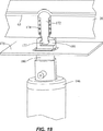
図20は、カートリッジ内の試料室、洗剤室、中和室、および試薬室に対して流体が制御されて流入および流出する様子を示している。これらの各室は、図20の室414で示されるように、ガスは通すが液体は通さない疎水性の膜410で覆われている。疎水性の膜410は、室414と圧力ポート32の間に位置付けられている。圧力ポート32は、カートリッジの頂部片22内に設けられ、室414の上に位置する。膜410は、キャリッジの運送や保管中に、仮にキャリッジが倒立したとしても、室414内に液体を保持する。圧力ポート32は、圧力ノズル812を収容するような寸法になっており、上記圧力ノズルは、通常外部の装置に設けられる圧力源(例えば真空ポンプまたは空気圧ポンプ)に接続される。ノズル182は、Oリング184とフランジ415とを有する。ばね185は、フランジ415に当接してノズル182を圧力ポート32に押し付け、Oリング184が圧力ポート32の周りのシールを確立する。運転において、正の空気圧または真空が、圧力ポート32を介して室414に加えられ、室414に対して液体を強制的に流入または流出させる。
【0057】
円錐状の弁座160(図15A,図15Bを参照して既に述べた)は、室414と接続流路411との間の液体の流れを制御すべく室414の下方のカートリッジの中央片24内に設けられている。弁は、フランジ187と、このフランジに当接して、アクチュエータ186に下向きの力が加わるまで弁を閉状態に保持するばね188とをもつ弁アクチュエータ188によって、開閉される。下向きの力は、弁を開くべくアクチュエータ186を押し下げるソレノイドによって加えられるのが好ましい。弁アクチュエータ186とソレノイドは、前述の装置に設けられる。
【0058】
図7,図8は、カートリッジの上面図と底面図を夫々示している。図9は、は、カートリッジの概略ブロック図である。図7〜図9のいずれにも示されるように、カートリッジは、カートリッジに流体試料を加えるポートをもつ試料室65と、この試料室65から延び出す試料流路とを有する。試料流路は、試料室65から延び出して、弁107を経て流路106に入る。流路106は、センサ域を有し、センサ域の流路106は、流路内に液体が存在することを容易に目視検出できる平坦な底部を有する。試料流路は、流路106から溶解室86に入ってフィルタスタック87を通る。試料流路は、流体が溶解室86から出る流路109と、平坦な底部の検出域137をもつ流路110と、弁111と、弁114を経て通気孔をあけた廃液室68に導く流路112とを有する。
【0059】
カートリッジは、また、洗剤溶液を保持する洗剤室66と、リジン試薬を保持する試薬室67とを有する。洗剤室66は、弁115、流路117および流路106を経て溶解室86に接続される。試薬室67は、弁119、流路117および流路106を経て溶解室86に接続される。試料成分(例えば、試料中の細胞またはウイルス)は、フィルタスタック87に捕捉され、溶解室86内で溶解されて試料成分から目標の分析対象物(例えば、核酸)が解き放たれる。カートリッジは、また、溶解室86から延び出して化学反応と光学的検出のための反応容器40へ、流体試料から分離された分析対象物を運ぶための分析対象物流路を有する。分析対象物流路は、溶解室86から延び出して、流路109、流路110および弁111を通る。分析対象物流路は、弁111を通った後、試料流路から分岐する。試料流路は、流路112を経て廃液室68に入る一方、分析対象物流路は、U字状流路122へ分岐する。次いで、分析対象物流路は、弁124を経て中和室70に流入した後、流出する。また、分析対象物流路は、弁126を経て主混合室71に流入した後、流出する。分析対象物流路は、主混合室71から流路122に沿って延び、弁127と流路80とポート41とを経て反応容器40に入る。
【0060】
反応容器40は、この反応容器に反応混合物を加えるためのポート41と、この反応容器から流体(例えば、空気または過剰な反応混合物)を出すためのポート43とを有する。カートリッジは、ポート43と連通する流路81を有する。流路81は、この流路に液体が存在することを検出するための平坦な底部の検出域130を有する。流路81は、流路131(流路131は、図7の上面図の紙面と垂直方向に真直ぐ下方へ延びる)に接続される。流路131は、流路132に接続され、流路132は、弁133を介して流路134(流路134は、図7の上面図の紙面と垂直方向に真直ぐ上方へ延びる)に接続される。流路134は、カートリッジからガスは逃がすが、液体は逃がさない疎水性の膜を有するベント36に繋がる。反応容器40の下流に位置する上記流路、ベントおよび弁は、操作の節で後述するように、反応容器の反応室42を加圧するために用いられる。
【0061】
カートリッジは、また、試料室65の上方に位置する第1圧力ポート105と、洗剤室66の上方に位置する第2圧力ポート116と、試薬室67の上方に位置する第3圧力ポート118と、中和室70の上方に位置する第4圧力ポート123と、主混合室71の上方に位置する第5圧力ポート125と、U字状流路122の上方に位置する第6圧力ポート128とを有する。カートリッジは、廃液室68と連通するセンサ室120,121を更に有する。センサ室120,121は、後に詳述するように、廃液室68に予め定められた体積の液体が収容されたとき、表示を行なう。
【0062】
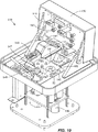
図10を参照すると、カートリッジは、1以上のカートリッジを収容するように設計された装置140と組み合わせて用いるのが好ましい。図解を明瞭化するた、図10に示された装置140は、カートリッジを1つだけ収容するものである。しかし、上記装置は、複数のカートリッジを同時に処理するように設計できるものと解釈されなければならない。装置140は、処理のためにカートリッジが入れられるカートリッジネストを有する。装置140は、カートリッジの溶解室内に圧力波を発生させるトランスデューサ92(例えば、超音波ホーン)と、カートリッジ内の9つの弁を動かす9つの弁アクチュエータ142と、弁アクチュエータを押し下げる対応する9つのソレノイド146と、キャリッジ内に形成された対応する6つの圧力ポートに接続するための6つの圧力ノズル145とを有する。更に、上記装置は、圧力ノズル145を経てカートリッジに圧力を供給する1以上の調整された圧力源に接続されるか、この圧力源を有する。適切な圧力源は、油差しポンプ、圧縮空気源、空気圧ポンプまたは外部圧力源への接続手段を有する。上記装置は、3つのスロット付き光学センサ143と、3つの反射型光学センサ144とを有する。
【0063】
図13は、センサ室120,121および試薬室67内の液体を検出するために設けられたスロット付き光学センサ143を示している。各センサ143は、組み込みLED(発光ダイオード)と、上記センサの反対側に配置されたホトダイオードとを有する。LEDは、光束を放射し、この光束は、実質上屈折させられないなら、ホトダイオードによって検出される。このようなスロット付き光学センサは、幾つかのメーカによって市販されている。カートリッジは、スロット付き光学センサが室67,120,121の周りに適合するような形状になっている。各センサの操作は、次のとおりである。センサが取り囲む室内に液体が存在しないなら、LEDからの光束は、室内の空気によって実質上屈折され、室の内壁で曲がって、あるとしても微弱な信号だけがホトダイオードによって検出される。なぜなら、空気は、プラスッチク製のカートリッジの屈折率とかけ離れた屈折率を持つからである。しかし、室内に液体が存在すると、LEDからの光束は、僅かあるいは全く屈折されず、ホトダイオードで検出される非常に強い信号が発生される。なぜなら、液体は、プラスチック製のカートリッジの屈折率に近似した屈折率を持つからである。従って、光学センサ143は、室67,120,121に液体が存在するか否かを決めるのに有用である。
【0064】
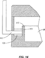
図14は、廃液室68に連通し、スロット付き光学センサ143によって囲まれたセンサ室120の概略破断側面図を示している。センサ室120とセンサ143は、予め定められた体積の液体が廃液室68に存在するとき、これを表示するために用いられる。センサ室120は、溢水リム152をもつ壁151によって廃液室68から部分的に分離されている。上記壁の高さは、予め定められた体積の液体が廃液室68に収容されたとき、この液体が溢水リム152を越えてセンサ室120に流れ込むように選ばれている。そして、センサ室120内の液体は、センサ143によって検出される。
【0065】
再び図13を参照すると、キャリッジは、廃液室68に連通する第2センサ室121を有する。第2センサ室121も、溢水リムをもつ壁153によって廃液室68から分離されている。壁153は、壁152よりも高くて、予め定められた第1の体積の流体に加えて予め定められた第2の体積の流体が廃液室68に収容されるまで、流体が壁153を越えて溢れないようになっている。センサ室120,121と光学センサ143は、カートリッジの操作を制御するのに役立つ。壁152の高さは、試料室65からの所定体積の試料流体が試料流路を経て廃液室68に流入したとき、試料流体がセンサ室120に溢れ出して検出されるように選ばれるのが好ましい。センサ室120での試料流体の検出は、洗剤室66からの洗剤溶液の放出を引き起こし、この洗剤溶液は、試料流路を経て廃液室68に流れ込む。廃液室68に収容される洗剤溶液の体積が増加すると、流体は壁153を越えてセンサ室121に流れ込んで、検出される。センサ室121で液体が検出されると、試薬室67からのリジン試薬の放出が引き起こされる。試薬室67を取り囲むセンサ143が、試薬室67が空であることを表示すると、超音波による溶解(溶菌)の開始が引き起こされる。これと択一的実施形態では、カートリッジは、試料用と洗剤用の2つの廃液室を有し、各廃液室は、それに接続された夫々のセンサ室を有する。
【0066】
インラインの反射型光学センサ144は、流路81,106,110の底部が平坦な検出域130,136,137内の液体の有無を決定するのに用いられる(図7)。各センサ144は、組み込まれたエミッタと、平坦な底部の検出域の上方に配置された検出器とを有する。エミッタは、光束を放出し、この光束は、カートリッジで反射されて検出器で検出される。センサは、空気/液体の境界が検出域を通過するとき、信号の変化を検出する。オプションとして、検出操作をより信頼性あるものにするため、2重エミッタの反射型光学センサを用いることができる。上記2種の反射型光学センサは、この技術分野で周知であり、市販されている。
【0067】
再び図10を参照すると、装置140は、カートリッジの反応容器を収容するためのスロット148をもつ熱交換モジュール147を有する。この熱交換モジュール147は、図28を参照して詳しく後述する。上記装置140は、カートリッジの上方の蓋150をラッチするラッチ機構149を有する。カートリッジネスト141は、カートリッジの脚を収容する整列穴401を有する。整列穴401は、ネスト内にカートリッジを適切に位置決めすることを保証し、その結果、圧力ノズル145、トランスデューサ92および弁アクチュエータ142は、キャリッジ内の対応するポートに嵌合し、反応容器は、スロット148に嵌合する。トランスデューサ92は、カートリッジがネスト141に入れられるとき、図5の破断図に示すように、溶解室86の底壁に接触するように装置140内に位置決めされなければならない。さらに、上記装置は、トランスデューサ92を溶解室86の壁に当接するように付勢するばねなどの機構を有する。
【0068】
装置140は、ソレノイド146、トランスデューサ92、熱交換モジュール147および光学センサ143,144の操作を制御するマイクロコントローラをもつ主論理ボードを含む図10に図示しない種々の慣用の装備を備える。上記装置は、この装置およびノズル145を経て空気圧を供給する空気圧ポンプに電力を供給する電源を備えるか、あるいは電源に接続される。装置140は、例えば操作の節で後述する機能を実行するべくプログラムされたマイクロコントローラなどを用いてコンピュータ制御されるのが好ましい。これと択一的に、上記装置は、分離したコンピュータまたは分離したコンピュータとオンボードのマイクロコントローラの組み合わせによって制御してもよい。
【0069】
図11は、装置140に処理のために載せられたカートリッジ20の等角投影図を示している。図11は、蓋150を開いた状態での装置140の部分破断図を示している。再び図11を参照すると、メモリまたはマイクロプロセッサのチップが、カートリッジ20の一部としてオプションで一体化される。上記チップは、カートリッジの種類などの情報、カートリッジを処理するための特定のプロトコルなどのプログラム情報、出し入れのための公差、クオリティ・トッラキングのための通し番号とロットコードおよび処理の結果を格納するための手段を有するのが好ましい。カートリッジ20に一体化された電子的メモリは、流体処理の種々のプロトコルに対して装置140を迅速、容易、かつエラーなくセットアップすることができる。カートリッジ20が装置140に挿入されると、この装置は、カートリッジ上のメモリに電子的に呼びかけて、挿入されたカートリッジについて実行されるべき流体処理のタイムシーケンスを制御するための適切な指令の組を自動的に受け取る。上記装置140は、単にカートリッジのメモリ中の各ステップを順に検索して実行するか、ユーザが例えばコントローラコンピュータを用いてシーケンスを編集できるように、メモリ中の内容をダウンロードする。
【0070】
カートリッジ上に、書込み可能なメモリ(例えば、紫外線消去型PROM(EPROM)や電気的消去型PROM(EEPROM))などの適切なメモリが含まれるなら、カートリッジに導入された試料に基づく中間および最終結果は、処理後の物理的試料と一緒に設けられた格納手段であるカートリッジのメモリに、上記装置によって書き込むことができる。このことは、試料と結果を保管することが必要な法医学などの適用例において、特に有利である。さらに、他の情報は、変更できない(または変更できる)形式でカートリッジのメモリに格納することができる。例えば、カートリッジの通し番号、製造ロット情報および関連する情報は、予めプログラムして変更不可にできる。ユーザのデータ、技術的な識別番号、試験日、試験場所および装置の通し番号は、変更できないようにカートリッジに書き込むことができる。このことは、試料を取り扱う際に「管理の鎖」による識別の容易化を可能にする。データ格納の分野の専門技術者は、電子的メモリ手段以外の光学的にアドレス付けられた印刷された領域(例えば、インクジェットや熱的)や磁気テープなどのメモリ手段を想起するであろう。
【0071】
図28は、反応混合物中の分析対象物を熱処理し、光学的に検出するために反応容器40が挿入される上記装置の熱交換モジュールを示している。この熱交換モジュール147は、モジュールの種々の構成要素を保持するハウジング208を備えるのが好ましい。上記モジュール147は、前述の熱板190を有する。ハウジング208は、反応容器40の反応室がスロットを経て上記熱板の間に挿入できるように、熱板190の上方に(図28に図示しない)スロットを有する。熱交換モジュール147は、好ましくはファン212などの冷却システムを有する。ファン212は、熱板、従って反応容器内の反応混合物を冷却すべく、熱板190の表面を通り越して冷却空気を送るような位置に設けられている。ハウジング208は、冷却空気を熱板190を越えてモジュール147の外へ向かわせる流路を区画するのが好ましい。
【0072】
熱交換モジュール147は、光学的な励起アセンブリ216と、反応容器40に収容された反応混合物を光学的に検査する光学的検査アセンブリ218とを更に有する。励起アセンブリ216は、その電子構成部材を保持するための第1回路板220を有し、光学的検査アセンブリ218は、その電子構成部材を保持する第2回路板222を有する。励起アセンブリ216は、反応容器中の蛍光的に標識付けされた分析対象物を励起するための1以上の光源(例えば、LED、レーザまたは電球)を有する。励起アセンブリ216は、光源からの光を平行にする1以上のレンズと、関係する励起波長領域を選択するフィルタとを有する。検出アセンブリ218は、反応容器40から放出される光を検出する1以上の検出器(例えば、ホトダイオード、光電子増幅管またはCCD)を有する。検出アセンブリ218は、放出光を集光し、平行にする1以上のレンズと、関係する放出波長領域を選択するフィルタとを有する。熱交換モジュール147で用いられる適切な光学的励起アセンブリと光学的検出アセンブリは、1999年11月25日に公開された国際公開WO 99/60380号公報(国際出願番号PCT/US99/11182号)に開示され、その開示内容は、参考のため本願明細書に一体化されている。
【0073】
光学アセンブリ216,218は、反応容器40の反応室が熱板190板の間に挿入されたとき、励起アセンブリ216が、透光性の側壁57A(図22参照)を介して反応室42と光学的に連通し、検出アセンブリが、透光性の側壁57B(図22参照)を介して上記反応室と光学的に連通するように、ハウジング208内に配置されている。好ましい実施形態では、光学アセンブリ216,218は、反応容器の反応室が熱板の間に挿入されたとき、光学アセンブリ216,218が側壁に直接接触するか、側壁に極接近するように、光学アセンブリ216,218を単に熱板190の底部縁に隣接して配置することによって、透光性の側壁と光学的に連通せしめられる。
【0074】
図34は、熱板190A,190Bの間に挿入された反応容器の反応室の部分破断等角投影図を示している(反応容器の頂部は切除されている)。反応容器は、透光性の側壁57A,57Bで形成された角度をなす(例えば三角形の)底部を有する。各熱板190A,190Bは、対応する形状の底部を有する。第1熱板190Aの底部は、第1底部縁250Aと第2底部縁250Bを有する。同様に、第2熱板190Bの底部は、第1底部縁252Aと第2底部縁252Bを有する。各熱板の第1および第2底部縁は、側壁57A,57Bが互いに偏る角度(例えば、90°)と同じ角度だけ互いに偏っているのが好ましい。さらに、熱板190A,190Bは、反応容器の反応室を挟んで収容するように配置されるのが好ましく、その結果、第1側壁57Aが実質上各第1底部縁250A,250Bの近傍にこれと平行に位置し、第2側壁57Bが実質上各第2底部縁252A,252Bの近傍にこれと平行に位置する。この配置は、透光性の側壁57A,57B、従って反応容器の反応室への容易な光学的アクセスを提供する。各光学アセンブリと側壁57A,57Bの間の光学的連絡を確立または改善するため、ゲルまたは流体がオプションとして用いられる。上記ゲルまたは流体は、結合される要素の屈折率に近い屈折率を有さなければならない。
【0075】
再び図28を参照すると、光学アセンブリ216,218は、励起光路と検出光路との間に90°の角度を与えるように配置されるのが好ましい。励起光路と検出光路の間の90°の角度は、反応室の第1側壁を経て入射する最少量の励起放射が、第2側壁を経て出射することを保証する。上記90°の角度は、また、第2側壁を経て集光されるべき最大量の放出放射を可能にする。好ましい実施形態では、反応容器40は、光学的検出のための反応容器40の適切な位置決めを保証すべく、光学アセンブリ216,218の間に形成されたスロットに嵌合する位置決めタブ58(図22参照)を有する。検出を改善するため、熱交換モジュール147は、反応容器40の頂部を覆って設けられ、反応容器が熱板190の間に挿入された後にハウジング208を遮光する遮光蓋(図示せず)を有する。
【0076】
本実施形態では、光学アセンブリ216,218を熱板190の底部縁に隣接して設けたが、他の配置も可能である。例えば、光学アセンブリ216,218と反応容器の側壁との間の光学的連絡は、光ファイバ、光パイプ、導波部材などの装置によって確立できる。これらの装置の1つ利点は、光学アセンブリ216,218を熱板190の物理的近傍に設ける必要がなくなることである。このことは、熱板の周りにより多くの空間を残し、この空間に冷却空気や冷媒を循環させて、冷却を改善することができる。
【0077】
熱交換モジュール147は、このモジュールの電子構成部材を保持するPCボード226と、このモジュール147を装置140(図10)に接続するエッジコネクタ224とを有する。熱板190上の加熱要素および温度センサと光学ボード220,222は、フレキシブルケーブル(図解の明瞭化のため図28には図示せず)によってPCボード226に接続される。熱交換モジュール147は、光学的検出回路をシールドするための接地トレース228を有する。熱交換モジュール147には、「加熱」、「冷却」、「完了」、「故障」などのモジュールの現在の状況をユーザに表示するLEDなどの表示器をオプションで設けることができる。
【0078】
ハウジング208は、剛で高性能なプラスチックまたは他の慣用の材料からモールド成形で作ることができる。ハウジング208の主たる機能は、熱板190、光学アセンブリ216,218、ファン212およびPCボード226を保持するための枠を提供することである。ハウジング208は、ファン212からの冷却空気を熱板190の表面を横切ってハウジングの外へ向かわせる流路とポートを有するのが好ましい。好ましい実施形態では、ハウジング208は、互いに嵌合することによって熱交換モジュール147の構成部材を挟んで囲む相補的部材片(図28の概略側面図には一方の部材片のみが示されている)を有する。
【0079】
図23を再び参照すると、熱板190A,190Bは、セラミックや金属を含む種々の熱伝導性材料で作ることができる。適切なセラミック材料は、窒化アルミニウム、酸化アルミニウム、酸化ベリリウムおよび窒化シリコンである。上記熱板を作ることができる他の材料は、例えば、砒化ガリウム、シリコン、窒化シリコン、酸化シリコン、水晶、ガラス、ダイヤモンド、ポリアクリル酸、ポリアミド、ポリカーボネート、ポリエステル、ポリイミド、ビニルポリマーおよびポリテトラフルオロエチレンなどのハロゲン化ビニルポリマーである。熱板の他の可能な材料は、クロム/アルミニウム、スーパーアロイ(耐熱合金)、亜鉛合金、アルミニウム、鋼、金、銀、銅、タングステン、モリブデン、タンタル、真鍮、サファイアあるいはこれ以外の当分野で利用できる種々のセラミック、金属またはポリマー材料である。
【0080】
本実施形態では、内面が非常に高い平滑度に都合良く加工できて高い耐摩耗性が得られ、高い耐薬品性と反応容器の柔軟な壁への良好な熱伝導性が得られることから、セラミック板が用いられている。セラミック板は、好ましくは略0.6〜1.3mmと非常に薄くすることができて、熱容量の低減によって非常に急速な温度変化を与えることができる。セラミックで作られた板は、良好な熱伝導体、かつ電気絶縁体であるので、板の温度は、この板に接続した抵抗加熱要素によって良好に制御することができる。
【0081】
種々の熱素子を熱板190A,190Bの加熱または冷却に用いることができ、従って反応室42内の反応混合物の温度を制御するここができる。一般に、板の加熱に適した素子は、導熱ヒータ、対流ヒータまたは放射ヒータである。導熱ヒータの例は、板に連結された抵抗加熱素子または誘導加熱素子である。適切な対流ヒータは、強制送風ヒータまたは板を貫流する流体用の流体熱交換器である。適切な放射ヒータは、赤外線ヒータまたはマイクロ波ヒータである。同様に、板を冷却するために種々の冷却素子を用いることができる。例えば、ファン、ぺルチェ素子、冷凍装置または板の表面を貫流する冷却流体用のジェットノズルである。これと択一的に、例えば板に直接接触する冷却された金属ブロックなどのヒートシンク等種々の熱伝導性の冷却要素を用いることができる。
【0082】
図24を参照すると、各板190は、外表面に配置された抵抗加熱要素206を有しているのが好まい。抵抗加熱要素206は、厚いか、または薄いフィルムであり、各板190、特に窒化アルミニウムまたは酸化アルミニウムのようなセラミック材料からなる板上に直接スクリーン印刷される。スクリーン印刷は、高い信頼性と、反応室内の熱を効率的に伝達するための小さな断面積とを有する。より均一な加熱を提供するため、例えば先端部で密に、中間部で疎に抵抗器を配置することによって、幾何学的なパターンを変えた厚いか、あるいは薄いフィルム抵抗器が、板の外側面に積層される。加熱要素を各板の外表面に積層するのが現在好ましいが、これと択一的に、特に板がセラミックの場合、加熱要素は、各板の内側に設けることができる。加熱要素206は、金属,タングステン,ポリシリコン, または電位差が加えられると、熱せられる他の材料で作ることができる。加熱要素206は、夫々の接点204と接続されている2つの端部を有しており、この接点204は、加熱要素に通電すべく電圧源(図24に示さない)に接続される。各板190は、また熱電対,サーミスタ,またはRTDのような温度センサ192を有するのが望ましく、この温度センサ192は、2つのトレース202によって夫々接点204に接続されている。温度センサ192は、制御された帰還ループで板190の温度を監視するのに使われる。
【0083】
上記板は、板の迅速な加熱や冷却を可能にすべく小さい熱容量を有する。特に、各板は、5J/℃以下、好ましくは3J/℃以下、最も好ましくは1J/℃以下の熱容量を有する。本明細書で使われているように、板の熱容量という用語は、板の質量と板の比熱の積として定義される。加えて、各板は、反応室の各主壁を覆うのに充分な大きさであるべきである。目下の好ましい実施形態では、各板は、例えば2mm〜22mmの範囲の幅Xと、2mm〜22mmの範囲の長さYと、0.5mm〜5mmの範囲の厚さを有する。各板の幅Xと長さYは、反応室の幅と長さより僅かに大きく選ばれている。さらに、各板は、図34を参照して前述したように、反応室の底部の外形に適合する角度をなす底部を有することが好ましい。また、好ましい実施形態では、各板は、0.75J/g℃の比熱を有する窒化アルミニウムで作られる。各板の質量は、0.005gから5.0gの範囲にあるのが好ましく、その結果、各板は、0.00375J/℃〜3.75J/℃の範囲の熱容量を有する。
【0084】
対向する板190は、反応室の柔軟な主壁が板の内面に接触して一致するように反応容器40の反応室を挟み込んで収容するように配置される。板190は、例えば、ブラケット,支持具,または保持具を用いることによって、お互いに対向して保持されることが目下好まれている。これと択一的に、板190は、国際公開第WO98/38487号で述べられているように、互いに近づくようにばねで付勢してもよく、上記国際公開の開示内容は、本明細書に参考として組み込まれている。本発明の他の実施形態では、板の1つは、固定位置に保持され、この一番目の板に向けて、二番目の板が付勢されている。もし、1以上のばねが板を互いに近づくように付勢するのに使われるなら、ばねは、壁が板の内面に一致せしめられるように充分な力で、板が容器の柔軟な壁に押し付けられることを保証するような充分な硬さであるべきである。
【0085】
図29と図30は、互いに対向して板190A,190Bを保持するための好ましい支持構造209を示している。図29は、支持構造の分解図を示し、図30は、支持構造の組立図を示している。図の明瞭化のために、支持構造209および板190A,190Bは、図28の熱交換モジュールでの正常な方向づけを逆にした状態で示されている。図29を参照すると、支持構造209は、内部に形成されたスロット148を有する取付板210を有する。スロット148は、反応容器の反応室が挿入できるくらいの充分な大きさである。間隔支柱230A,230Bは、スロット148の両側で取付板210から延び出ている。間隔支柱230Aは、その対向する両面に形成された窪み232(図29の等角投影図では片側のみが見える)を有し、間隔支柱Bは、その対向する両面に形成された窪み234(図29の等角投影図では片側のみが見える)を有している。間隔支柱での窪み232,234は、板190A,190Bの端部を収容するためにある。上記構造を組み立てるために、板190A,190Bは、板の縁が窪み232,234内に位置するように間隔支柱230A,230Bの両側に置かれている。そのとき、板の縁は、適切な保持手段を用いて窪み内に保持される。好ましい実施形態では、板は保持クリップ236A,236Bによって保持される。これと択一的に、板190A,190Bは、接着剤,ねじ,ボルト,クランプ,または他の適切な手段によって保持することができる。
【0086】
取付板210および間隔支柱230A,230Bは、全体的にプラスチックの単一のモールド成形片として作るのが好ましい。上記プラスチックは、板190A,190Bが熱せられたとき、溶けて変形しないポリエチルイミドのような高温プラスチックであるべきである。保持クリップ230A,230Bは、ステンレス鋼であることが好ましい。取付板210は、各可撓ケーブル238A,238Bを支持するための窪み240A,240Bをオプションで備えてもよく、上記可撓ケーブル238A,238Bは、加熱要素および板190A,190B上に配置された温度センサを熱交換モジュール147(図28)のPC板226に接続している。板190A近傍の柔軟なケーブル238Aの部分は、一片のテープ242Aによって、窪み240A内に保持され、板190B近傍の柔軟なケーブル238Bの部分は、一片のテープ242Bによって、窪み240B内に保持される。
【0087】
図31は、組み立てられた支持構造209の等角投影図である。取付板210は、その両面から延び出し、熱交換モジュールのハウジングに支持構造209を固定するためのタブ246を有するのが好ましい。図28を再び参照すると、ハウジング208は、取付板210を所定位置に確実に保持すべく上記タブを保持するためにスロットを含むのが好ましい。これと択一的に、取付板210は、例えば、接着剤,ねじ,ボルト,クランプ、または他の適切な手段を使ってハウジング208に取り付けることができる。
【0088】
図29を再び参照すると、支持構造209は、板190A,190Bの内面が互いに非常に僅かな角度で傾くように、板190A,190Bを支持することが好ましい。好ましい実施形態では、間隔支柱230A,230Bは、板190A,190Bが壁の対向する側に押し付けられるとき、板の内面が互いに僅かに傾くようになる僅かに先細になった壁244を有する。図23で最も良く示されているように、板190A,190Bの内面は、室42が挿入される僅かにV字形状となるスロットを形成すべく、互いに傾いている。内面が互いに傾いている量は、非常に僅かであり、平行から略1°傾けられるのが好ましい。両内面は、板190A,190Bの間に反応室42が挿入される前に、板の底部が板の頂部よりも互いに僅かに近づいているように傾けられる。この内面の僅かな傾きは、反応容器の反応室42を板の間に一層簡単に挿入し、板の間から反応容器の反応室42を一層簡単に抜き取ることを可能にする。これと択一的に、板190A,190Bの内面は、互いに平行にすることもできるが、このとき反応容器40の挿入および抜き取りは一層難しくなる。
【0089】
加えて、板190A,190Bの内面は、枠46の厚さと同じ距離だけ互いに隔たるのが好ましい。内面が互いに傾けられる実施形態では、内面の中心は、枠46の厚さと同じ距離だけ互に隔てられ、板の底部は、最初は枠46の厚さよりも僅かに小さい距離だけ隔てられるのが好ましい。室42が、板190A,190Bの間に挿入されたとき、剛枠46は、反応室42が板の間に強固に挟まれるように、板の底部を互いに離間するように強制する。板190A,190Bが枠46によって、互いに離間させられる距離は非常に小さく、例えば、枠の厚さが1mmであって内面が互いに1°傾いているならば、略0.035mmである。
【0090】
図30を再び参照すると、保持クリップ236A,236Bは、板190A,190Bのこの僅かな外側への移動を許容すべく充分柔軟でなければならないが、反応容器の挿入や除去の際、間隔支柱230A,230Bの凹部内に板を保持すべく充分堅くなければならない。板190Aと板190Bの間への反応容器の押し込みは、反応室に初期の予荷重を与えて、反応室の柔軟な主壁が圧縮されたとき板の内面と良好な熱的接触を達成することを保証する。
【0091】
図28を再び参照すると、容器40の加圧のために、板190が離間する量を限定するために、停止部が光学アセンブリ216,218のハウジング内にモールドされる。図32に示すように、光学アセンブリ218のハウジング249は、ハウジングから外側に延在する鉤爪状の停止部247A,247Bを含む。図33に示すように、ハウジング249は、板190A,190Bの底部縁が停止部247A,247Bの間に挿入されるように配置されている。このようにして、停止部247A,247Bは、板190A,190Bが予め決められた最大距離から更に広がるのを防止している。わかりやすくするために図33には示されていないが、光学アセンブリ216(図28を参照)は、予め決められた最大距離よりも板の片割が互いに広がるのを防止するために、対応した停止部付きのハウジングを有している。図23を再度参照すると、停止部によって板190A,190Bの内面が互いに間隔の開けられる最大距離は、枠46の厚みにぴたりと合致しなければならない。好ましくは、板190A,190Bの内面の最大間隔は、枠46の厚みよりも僅かに大きくして、容器40および板190A,190Bにおける公差の変化に適合させる。例えば、上記最大間隔は、枠46の厚みよりも約0.1〜0.3mm大きいことが好ましい。
【0092】
図35は、熱交換モジュール147の電気構成部品の概略ブロック図である。上記モジュールは、装置の主要ロジックボードに接続するためのコネクタ224または可撓性ケーブルを含む。上記モジュールは、また、熱板190A,190Bを含み,各板は上述した抵抗型加熱要素を有する。上記熱板190A,190Bは、上記装置からの電力入力253を受けるために平行に配線されている。上記熱板190A,190Bは、また、デジタル信号をアナログ−デジタルトランスデューサ264に出力する温度センサ192A,192Bを含んでいる。トランスデューサ264は、アナログ信号をデジタル信号に変換し、それらをコネクタ224を介してマイクロコントローラに送る。
【0093】
熱交換モジュールは、また、熱板190A,190Bと、上記熱板間に挿入された容器内の反応混合物とを冷却するために、ファン212のような冷却システムを含んでいる。上記ファン212は、電力スイッチ272を入れることによって作動され、この電力スイッチ272は、今度はマイクロコントローラからの制御信号を受信する制御ロジックブロック270によって制御される。上記モジュールは、さらに、反応混合物内の標識付き分析物を励起するために例えばLED200のような4つの光源と、反応混合物からの蛍光放射を検出するために好ましくはフォトダイオードのような4つの検出器198とを含んでいる。上記モジュールは、また、各LEDに可変電流量(例えば、0〜30mAの範囲)を供給するために調整可能な電流源225を含んで、LEDの明るさを変化させる。デジタル−アナログトランスデューサ260は、調整可能電流源255とマイクロコントローラとの間に接続されていて、マイクロコントローラが電流源をデジタル的に調整する。
【0094】
調整可能な電流源255は、好ましくは、各LEDが作動されたときに略同じ明るさを有するように用いられる。製造の変動により、多くのLEDは同一量の電流を与えても明るさが異なる。したがって、現在の所、熱交換モジュールの製造中に明るさの試験を実施し、且つ、モジュールのメモリ268に較正データを蓄えることが望ましい。較正データは、各LEDに与えるべき電流の正しい量を示す。マイクロコントローラは、メモリ268から較正データを読み、それに応じて電流源255を制御する。
【0095】
上記モジュールは信号調節/利得選択/オフセット調整ブロック262を含み、上記ブロックは増幅器とスイッチと電子フィルタとデジタル−アナログトランスデューサとから成る。ブロック262は検出器198からの信号を調整して、利得を増加させ、オフセットし、ノイズを減少させる。マイクロコントローラは、デジタル出力レジスタ266を通して上記ブロック262を制御する。出力レジスタ266はマイクロコントローラからのデータを受け取って、ブロック262に制御電圧を出力する。上記ブロック262は、アナログ−デジタルトランスデューサ264とコネクタ224とを介して、調整された検知器信号をマイクロコントローラに出力する。モジュールは、また、好ましくはシリアルなEEPROMのようなメモリ268を含んで、LEDや熱板190A,190Bや温度センサ192A,192Bの較正データなどのモジュールに特有のデータを保存する。
【0096】
カートリッジおよび装置の操作について述べる。図3に示されるように、分析される流体試料は、試料ポートを通して試料室65に添加され、キャップ30はポート64にねじ込まれてポートを密封する。図10を参照すると、次に、カートリッジ20は、処理のために装置140のカートリッジネスト141の中に配置される。初めに、カートリッジ20内の総ての弁は、カートリッジが装置140内に配置されたとき、閉じられている。カートリッジが装置内に配置されるとき、トランスデューサ92は、図5に示すように、溶解室86の底壁を形成する可撓性ガスケット63の外面と接触する。
【0097】
図10を再度参照すると、好ましくは、装置140は後述する機能を果すためにコンピュータ制御される。例えば、弁アクチュエータ142を使用してカートリッジ内での弁の開閉、ノズル145を経るカートリッジへの加圧、トランスデューサ92の作動、光学サンサ143,144を使用した液体の有無の検出と液体レベルの検出、熱交換・光学検出モジュール147の制御である。下記の記述に基づいてこれらの機能を果すために、当該技術分野において通常の知識を有するプログラマは、マイクロコントローラとコンピュータのいずれか一方或いは両方をプログラムすることができる。
【0098】
図9を参照すると、好ましくは、差圧を利用して液体は強制的にカートリッジを貫流させる。カートリッジ内の液体流を制御するために、ここでは正圧が記載されているが、負圧(真空)が使用されてもよい。通常、印加することのできる正圧の最大値は、平方インチ当たり30ポンド(30psi)以上の液体突破圧力に到達し得る疎水性膜によって制限される。圧力の下限値は、分析目標に適うべく、カートリッジを介して試料および他の液体を充分迅速に移動させる必要性によって限定される。例えば、1psi以下では、試料はフィルタスタック87を通して充分に流れない可能性がある。一般的に、6〜20psiの範囲の圧力が適切である。カートリッジを通る試料流量は、好ましくは、10〜30ミリリットル/分の範囲である。洗剤流量はより少なく、溶解室86を有効に洗浄するために、洗剤流量は例えば6〜18ミリリットル/分である。
【0099】
カートリッジの操作を図解するために、特定プロトコルを、図9を参照しつつ述べる。理解されたいのは、これは1つの可能なプロトコルの一例に過ぎず、本発明の範囲を限定するものではないことである。初めに、流体試料が試料室65から強制的に流される前に、上記カートリッジに洗剤液が注入される。カートリッジに注入するには、弁111と115とが開かれて10psiの圧力が圧力ポートを通して室66に約2秒間加えられる。少量の洗剤液は、流路117,106と溶解室86と流路109,110とを通って、U字形流路122に流れ込み、圧力ポート128の下の疎水性膜に至る。
【0100】
注入に続いて、弁115と圧力ポート116とが閉じられ、弁107と114が開かれる。同時に、20psiの圧力が、約15秒間圧力ポート105を介して試料室65に印加される。その結果、試料は、流路106を通り、室87内のフィルタスタック87を通り、流路110,111,112を通って、換気された廃水室68内に強制的に流れ込む。試料が流路106内のセンサ域136を通過するので、光学センサ144(図13)を用いて、試料室65が何時空になったかを決定することができる。試料液がフィルタスタック87を貫流するとき、試料内の標的細胞あるいはウイルスが捕獲される。予め決められた量の試料が廃水室68に到達すると、液体が溢れ出てセンサ室120内に入り、プロトコルにおける次ステップの誘因となる。この代りに、光学センサからのフィードバックを用いてものごとの誘因とするのではなく、予め決められたプロトコルのステップをタイム設定して、例えば、予め決められた圧力を予め決められた時間印加して、既知量を既知の流速で移動させる。
【0101】
溶解室86の貫流設計では、比較的大きな試料容積からの標的細胞やウイルスがずっと小さな容積に濃縮されて増幅および検出される。このことは、例えば核酸のような試料内の低濃度分析物を検出するために重要である。特に、室86の収容容積に対する溶解室を強制的に貫流させる試料の容積の比は、好ましくは少なくとも2:1であり、より好ましくは少なくとも5:1である。室86を強制的に貫流させる試料の容積は、好ましくは少なくとも100μリットルであり、より好ましくは少なくとも1μリットルである。目下好ましい実施形態においては、5ミリリットルの試料容積は溶解室86を強制的に貫流し、室86は約0.5ミリリットルの収容容積を有している。したがって、その比は10:1である。さらに、溶解室86は、試料が室を通って強制的に流されるときに、(例えば、室の壁に結合された超音波ホーンを使用して)超音波処理される。室86を超音波処理することは、フィルタスタック87の目詰りを防ぎ、室86を通る流れがより均一になる。特に、音波は、フィルタ内の特定の物質またはビーズがフィルタを目詰りさせないようにするのを助ける。
【0102】
次のステップでは、弁111,114,115が開かれ、20psiの圧力が約7秒間洗剤室66に印加されて、流路117,106を通って溶解室86内に洗剤液を強制的に流し込む。洗剤液は、PCR抑制物質と溶解室86からの汚染物質を洗浄し、汚染物質を流路109,110,112を通って廃水室68に移動させる。このために、pHとか溶質成分とかイオン力の異なる様々な適切な洗剤液が使用され、そして、これらの洗剤液は当該分野において周知である。例えば、適切な洗剤試薬は、80mMの酢酸カリウム溶液であり、8.3mMのトリスHClであり、pH7.5で40μMのEDTAであり、55%のエタノールである。洗剤液を室に強制的に流している間、(例えば、室の壁に結合された超音波ホーンを使用して)溶解室86は超音波処理される。室86の超音波処理は、前述したように、フィルタスタック87の目詰りを防ぎ、室86に流体をより均一に貫流させる。さらに、上記音波は、物質を緩めて洗い流すのを促す。洗剤液は容積が増加すると廃水室68に到達して、液の一部が溢れてセンサ室121内に入り、プロトコルにおける次のステップの誘因となる。
【0103】
次のステップでは、弁115が閉じられ、弁119が開かれる。15psiの圧力が、約3秒間、圧力ポート118を介して試薬室67に印加される。上記圧力は、溶解室67から流路117,106を通って溶解室86さらに流路110内に強制的に流される。室86はこのようにして液体で満たされる。適切な溶解試薬は、例えば、グアニジン塩化水素、グアニジンチオシアン酸塩、グアニジンイソチオシアン酸塩、沃化ナトリウム、尿素、過塩素酸ナトリウム、臭化カリウム等の攪乱塩を含有する溶液を含む。目下好ましい実施例では、PCRを抑制しない溶解試薬が使用される。溶解試薬は、10mMのトリス、5%のツウィーン-20、1mMのトリス(2カルボキシホスフィン塩酸塩)、0.1mMエチレングリコールビス(bアミノエチルエーテル)−N,N,N’、N'テトラセティク酸を有する。溶解室86が溶解試薬で満たされた後、弁111,114は閉じられる。弁119は開かれたままで、20psiの圧力が圧力ポート118に印加される。したがって、フィルタスタック87に捕獲された細胞あるいはウイルスを溶解する準備段階では、溶解室86内の静圧は20psiまで増加する。
【0104】
図5を再度参照すると、溶解室86の加圧は、トランスデューサ92と溶解室86の可撓性壁63との間の結合を確実かつ有効なものにするので重要である。溶解室86内の細胞あるいはウイルスを崩壊させるために、トランスデューサ92が作動される(すなわち振動運動するようにセットされる)。溶解室86の可撓性壁63は、僅かな偏向によって、壁内に高圧を生じることなくトランスデューサ92の振動を室86内の液体に伝える。上述したように、壁63はエラストマの膜によって形成される。この代わりに、壁は、好ましくは0.025〜0.1mmの範囲にある厚みのポリマ材の膜またはシート(例えばプリプロビレン膜)である。トランスデューサ92は、好ましくは、室86を超音波処理するための超音波ホーンである。室86は、好ましくは、20〜60kHzの範囲にある周波数で10〜40秒間超音波処理される。例示のプロトコルでは、室は47kHzの周波数で15秒間超音波処理される。ホーンチップの振幅は、好ましくは、20〜25μmの範囲にある(ピーク間で測定)。
【0105】
トランスデューサ92の頂部が振動するとき、それは可撓性壁63に繰返し衝撃を与える。(図6では上方向の)前進ストロークでは、トランスデューサ92の頂部は壁63を押圧して、室86内に圧力パルスすなわち圧力波を発生する。(図5では下方向の)後退ストロークでは、通常、トランスデューサ92の頂部が可撓性壁63から離れ、可撓性壁63はトランスデューサと同じ周波数で動くことができない。次の前進ストロークでは、再び、トランスデューサと壁とが互いに作用しながら、トランスデューサ92の頂部は壁63に正面衝突しながら衝撃を与える。トランスデューサ92が振動するときにトランスデューサ92と壁63とが分離するので、トランスデューサの有効前進ストロークはピーク間の振幅よりも小さくなる。上記有効前進ストロークは、溶解室86内での超音波処理のレベルを決定する。したがって、分解室86の静圧を増加させることが重要となり、トランスデューサ92の頂部が後退した時は、可撓性壁63が強制的に外方に押しやられて頂部と当接する。トランスデューサ92の有効前進ストロークによって圧力パルスまたは圧力波が室内で確実に発生するように、上記室86内の静圧は充分なものでなければならない。目下のところ、室86内での静圧を、カートリッジの外の雰囲気圧よりも少なくとも5psiまで増加させることが好ましく、さらに、雰囲気圧よりも15〜25psiの範囲の圧力に増加させることがより好ましい。
【0106】
各前進ストロークでは、トランスデューサ92は、室内の液体に速度を付与して、室86内を迅速に一掃する速度パルスを発生させる。フィルタスタック87(図6)内のビーズは室86内で圧力パルスによって攪拌される。圧力パルスは室86内でビーズを激しく動かし、ビーズは細胞やウイルスを機械的に破壊して、それらから物質(例えば、核酸)を解放する。血液細胞などの或る種の細胞は、比較的脆弱で、ビーズを用いることなく圧力波のみを用いて崩壊させることができる。その他の細胞(特に胞子)は非常に耐性のある細胞壁を有していて、一般的に有効な溶解にはビーズが必要とされる。
【0107】
図9を参照すると、細胞やウイルスの崩壊に続いて、弁111,124が開かれ、12psiの圧力が圧力ポートを介して試薬室67に約4秒間供給される。この圧力によって強制的に、溶解試薬がフィルタスタック87から核酸を溶離させ、核酸と共に中和室70内に流れ込む。(例えば、室の壁に結合された超音波ホーンを用いて)溶解室86を超音波処理して、核酸を溶離することができる。室86の超音波処理は、上述したように、フィルタスタック87の目詰りを防止する。室420は、溶解試薬を中和するために、洗剤などの中和剤で部分的に充填(例えば半分ほど充填)される。PCRに対して非抑制な溶解試薬が使用されるならば、中和剤はオプションとなる。
【0108】
次のステップでは、弁124が閉じられて、室70内に溶解試薬と分析物と中和剤とが収容される。弁114が開かれ、15psiの圧力が圧力ポート128を介して約3秒間印加されて、U字形流路122内の液体を廃水室68に強制的に流し込む。次に、弁124,126が開かれ、15psiの圧力が中和剤室70の頂部の圧力ポート123を介して約5秒間印加される。この圧力によって強制的に、室70内の中和された溶解試薬と核酸とが、流路122に流れ、主混合室71に流れ込む。そのとき、主混合室71の弁126は閉じられている。上記主混合室71は、PCR試薬と、中和された溶解試薬と核酸とを混合している蛍光プローブとを含有して、反応混合物を形成している。
【0109】
次のステップでは、廃水室68への弁144を開くことによって流路112が一掃され、15psiの圧力が圧力ポート128に約1秒間印加される。次のステップでは、主要混合物室71に形成された反応混合物が、以下のようにして反応容器40に移動される。すなわち、弁126,127,133が開かれ、15psiの圧力が、主混合物室71の頂部にある圧力ポート125に約6秒間印加されて、反応混合物が、流路122と弁127と流路80を通って強制的に流され、ポート41を経て反応室40に至る。反応混合物は室内の空気と置き換わって容器の室42を満たし、空気は出口流路52を通って出て行く。この出口流路52を通って出る空気は、流路81内を移動しセンサ域130を通り過ぎて流路131内に入る。空気は、流路131から流路132内に流れ、弁133と流路134とを通って、通気孔36を経てカートリッジを出る。室42を満たすのに充分な容積の反応混合物が容器内に流れ、過剰となった反応混合物は、出口流路を経て容器から出て行く。過剰反応混合物は、流路81に流れ込み、センサ域130において光学的に検出される。反応混合物が検出されたときは、弁133が閉じられ、圧力ポートからの圧力が印加されて反応室42を加圧する。
【0110】
図23を再度参照すると、室42内を加圧することによって容器の可撓性主壁が膨張する。特に、上記圧力は、主壁48を板190A,190Bの内面と強制的に接触させ、一致させる。これによって、板190A,190Bと室内の反応混合物との間で最良の熱伝導が確実に行なわれる。雰囲気圧力よりも2〜30psi上の圧力に室42を加圧することが目下のところ好ましい。この圧力範囲が目下のところ好ましいのは、一般的に2psiが、壁48と板190A,190Bの表面との間を一致させるに充分な圧力である。30psi以上では、壁48の破裂や枠46とか板190A,190Bの変形、あるいはカートリッジ内の膜の破裂を引き起こす可能性がある。より好ましくは、室42が雰囲気圧力よりも8〜15psi上の圧力に加圧されることである。この圧力範囲がより好ましいのは、上述の実用限界内に安全に収まっている為である。室42が加圧されると、容器40内の反応混合物は熱的に処理されて、混合物内の標的分析物の存否を決定する光学的応答指令信号が送られる。
【0111】
図35を参照すると、目標温度と温度センサ192A,192Bからの帰還信号とを用いた標準的な比例積分微分(PID)制御を使用して、反応混合物は板190A,190B間で熱的に処理される。比例は、「オフ」の時間に対する「オン」の時間の比を変化させることによって行なわれるか、或いは、好ましくは、比例アナログ出力を用いて行なわれる。上記比例アナログ出力は、板190A,190Bの実際の温度が所望の設定温度に接近するにつれて、板190A,190Bの加熱要素あるいはファン212への供給平均電力を減少させる。PID制御は、比例モードに、自動リセット機能(時間に対して偏差信号を積分する)と比率処置(レイトアクション、微積信号を合計して比例帯を移動させる)とを組み合せたものである。標準PID制御は当該技術分野では周知であり、ここでこれ以上の説明は不要である。この代わりに、反応混合物は、国際公開番号WO99/48608(出願番号PCT/US99/06628)に記載されているPID制御の修正版を使用して、熱的な処理が施されてもよい。なお、上記文献の開示内容はこの参照によって本文に編入される。
【0112】
反応混合物は板190A,190Bの間で熱的なサイクルを受けて、混合物内の1以上の標的核酸配列を増幅させる。上記混合物は、好ましくは各熱サイクルの最低温度点において、応答指令信号が光学的に送信される。光学的な指令応答は、各発光ダイオード(LED)200を連続的に作動させ、混合物内の異なる蛍光で標識付けされた分析物を励起させ、検知器198を用いて室42から放出される光を検出することによって行なわれる。図22を再び参照すると、好ましくは、励起ビームは透光性の側壁57Aを通して室42内に伝達され、一方、放出された蛍光は側壁57Bを通して検出される。
【0113】
本発明のカートリッジの利点の一つは、比較的大きな容積の例えば数ミリリットル以上の流体試料から内細胞物質を分離させることができ、ずっと少ない容積の例えば100ミリリットル以下の反応液に濃縮できる。カートリッジは、ミリリットルの量の流体試料から物質を効率よく抽出することによって、並外れた濃度比率になる。特に、試料室65は、好ましくは、100μリットル〜12ミリリットルの収容容積を有する。より好ましくは、試料室65は、少なくとも1ミリリットルの収容容積を有する。1ミリリットルという下限値が好ましい理由は、核酸のような低濃度の分析物を検出するためには、少なくとも1ミリリットルの試料が分析されなければならないからである。12ミリリットルという上限値が好ましい理由は、12ミリリットル以上の試料は、ずっと大きなカートリッジを必要とし、フィルタスタックが目詰りし易いからである。目下好ましい実施の形態では、試料室は、試料を5ミリリットル保有するために5.5ミリリットルの収容容積がある。
【0114】
洗剤室66は、溶解室86の容積と比例する収容容積を有している。特に、洗剤室66は、好ましくは溶解室86の容積の少なくとも1〜2倍の洗剤容積を有して、室86からPCR抑制物および残骸物(デブリス)を洗い流すのに充分な洗剤液が存在するのを保証する。目下好ましい実施の形態では、溶解室の容積は約0.5ミリリットルであり、洗剤室66の容積は、洗剤液を保持するために2.5ミリリットルである。0.5ミリリットルという溶解室66の容積は、フィルタスタック87の目詰りを避けるための充分に大きなサイズと、分析物を小さな容積に濃縮して改良された増幅と検出とをするための充分に小さなサイズとの間の妥協である。
【0115】
試薬室67は、室を加圧して室から核酸を抽出するのに充分な溶解試薬が存在するには、溶解室86の容積の少なくとも1倍乃至2倍の溶解試薬容積を収容能力があるものが好ましい。目下好ましい実施形態においては、室67は、約1〜1.5ミリリットルの溶解試薬を収容するために、1.5ミリリットルの収容容積を有している。廃水室68は充分な収容容積を有していて、試料と洗剤液と未使用の溶解試薬とを収容する。廃水室68は、好ましい実施形態では、約9.5ミリリットルの収容容積の寸法に作られている。
【0116】
室70内の中和剤が溶解室86に充填された溶解試薬の容積を中和するので、中和室70のサイズは溶解室86の容積に左右される。溶解室は0.5ミリリットルの容積を有することが目下のところ好ましく、約0.5ミリリットルの中和剤を収容するために室70は1.0ミリリットルの収容容積を有する。中和剤は0.5ミリリットルの溶解試薬と溶離された分析物とが混合される。主混合物室71の収容容積は、反応混合物を製造するために充分なものであるべきで、容器40を充填し、上記容器に導く流路122,127を充填する。目下好ましい実施形態において、主混合物室は、初期負荷となる100μリットルの主混合物を収容するために、200μリットルの収容容積を有する。この主混合物には、反応混合物を形成するために、100μリットルの中和溶解試薬と溶離分析物とが付加される。
【0117】
カートリッジ内の流路流路は、断面が略D形をしていて(ガスケットは流路の平坦な側面を形成している)、好ましくは1/64〜1/8インチ(0.4〜3.2mm)の幅または直径を有し、より好ましくは1/32〜1/16インチ(0.8〜1.6mm)の幅を有している。これらの範囲は、流路が狭くなる(流れが制限される)のを防ぐと共に、流路が広く成り過ぎる(未使用の液体が流路内に停滞する)のを防ぐために、目下のところ好ましいものである。
【0118】
上記カートリッジおよび装置の構造と操作については、多くの変更が代替えの実施形態において可能である。例えば、PCRによる増幅が目下のところ好ましいが、熱サイクル増幅法と等温増幅法との両方を含む何らかの増幅法を用いて、上記カートリッジと装置とは核酸配列を増幅するために使用され得る。適切な熱サイクル法には、ポリメラーゼ連鎖反応(PCR、米国特許第4,683,202号、米国特許第4,683,195号、米国特許第4,965,188号)、逆転写酵素PCR(RT−PCR)、DNAリガーゼ連鎖反応(LCR、国際特許出願第WO89/09835)、転写ベース増幅(D.Y. Kwoh et al. 1989、Proc. Nt. Acad. Sci. USA 86, 1173-1177)がある。但し、これらに限定されるというものではない。本発明の実施に当たって有用かつ適切な等温増幅法は、限定されるものではないが、ローリングサークル増幅、ストランド置換増幅(SDA、Walker et al. 1992, Proc, Nati, Acad. Sci. USA 89, 392-396)、Qベータレプリカーゼ(Lizardi et al. 1998, Bio/Technology 6, 1197-1202)、核酸ベースの配列増幅(NASBA、R. Sooknanan and L. Malek 1995, Bio/Technology 13, 563-65)、自己維持配列複製(3SR、Guatelli et al. 1990, Proc. Nati. Acad. Sci. USA 87, 1874-1878)を含む。
【0119】
さらに、上記カートリッジと装置とは、核酸増幅以外の化学反応を行なうために、使用されることができる。また、カートリッジ内の分析物を検出するためには、蛍光励起および放出検出が好ましいが、軸上結合構造(on-axis geometries)との直接吸収および/または透過に使用される光学的検出法が使用されてもよい。もう1つの可能な検出法は、時間減衰蛍光法である。さらには、上記カートリッジは、蛍光標識に基づいた検出に限定されるものではない。例えば、検出は、燐光標識または化学ルミネセンス標識または電気化学ルミネセンス標識に基づいてもよい。
【0120】
流体試料は、様々な手段によって手で或いは自動的にカートリッジ内に導かれる。手による添加では、測定された量の物質が入口ポートを通してカートリッジの収容領域内に置かれ、次にキャップが上記ポート上に配置される。これの代わりに、分析に必要とされる量よりも多い試料物質がカートリッジに添加され、カートリッジ内の機構が、所定のプロトコルに対して必要な試料を正確に測定し、等分し得る。例えば細胞生検物質や土壌や糞や滲出物やその他複合物等の試料を別の装置または付属器に搭載し、次に、上記副装置または付属器をカートリッジ内に搭載することが望まれる。例えば、一片の細胞は、2次装置の管腔内に載置されて、カートリッジの入口ポートに対してキャップとして機能する。上記キャップは上記ポート内に押圧されると、細胞はメッシュに強制的に通されて、上記メッシュは細胞を薄切り或いは分割する。
【0121】
自動的に試料が導入される場合には、カートリッジの添加設計の特徴が用いられていて、多くの場合、試料の増大機能をカートリッジに直接分与している。或る試料の場合、例えば人のレトロウイルス病原体のような操作者や環境に危険を呈するような場合には、試料のカートリッジへの移動は危険なものとなり得る。したがって、一実施形態においては、外部の流体試料をカートリッジ内に直接移動させる手段を設けるために、注入器が装置に組み込まれている。この代わりに、静脈穿刺針と吸引血液管とがカートリッジに取り付けられて、血液試料を採取するために用いられるアセンブリを形成する。採取後に、上記管と針は取り外されて廃棄される。そのとき、カートリッジは器具内に設置されて処理される。この方法の利点は操作者または環境が病原体に晒されないことである。
【0122】
入口ポートは、意図された試料の特性の関数として適当な人間的要因を考慮しつつ設計され得る。例えば、呼吸系の試料は、咳の喀出粘液として、或いは、喉や鼻腔の背後から綿棒または刷毛で集めた試料として、低呼吸管から得ることができる。前者の場合、入口ポートは、患者がカートリッジ内に直接咳ができるように、さもなければ、喀出試料をカートリッジ内に容易に吐けるように設計されている。刷毛または綿棒の試料に対しては、試料は入口ポート内に置かれ、ポートと閉塞部の特徴によって、カートリッジの収容領域内で綿棒または刷毛の端部を容易に折ったり保持したりできる。
【0123】
別の実施形態では、カートリッジは入口管および出口管が、例えば水流のような非常に大きな容積の試料プール内に配置されていて、試料物質はカートリッジを貫流する。この代わりに、カートリッジ全体が試料内に直接浸漬されるように、親水性の芯材が反応領域として機能し、充分な量の試料が上記芯材の中に吸収される。次に、上記カートリッジは取り除かれ、実験室に運ばれるか、あるいは携帯型器具を用いて直接分析される。別の実施形態では、配管を用いて、管の一端はカートリッジと直接連通させて少なくとも1つの反応領域との流体界面を与えると共に、管の他端は外部環境と接触できて試料の受取部として機能する。次に、上記管は試料内に配置され、ストローとして機能する。また、カートリッジ自体は実際の試料収集装置として機能し、これによって取り扱いが簡単になり不便さを減少させる。法的争いや犯罪調査に関わる試料の場合、試験物質を直接接近して流体のカートリッジ内に持ち込むことは、一連の保護された状態が都合良く且つ確実に保たれるので利点となる。
【0124】
図9を参照すると、試薬は使用前にカートリッジ内に外部から導入され、例えば、試薬室67と中和剤室70と主要混合物室71の密封できる開口部を通して導入される。この代わりに、例えば、水溶液あるいは再構成を必要とする乾燥された試薬のような試薬は、製造中にカートリッジ内に置かれてもよい。反応が液相なのか固相なのかを含めた、試薬の固有熱安定性、再構成速度、反応速度など様々なパラメータに基づいて、特定のフォーマットが選定される。溶液のときに熱的に不安定な化合物を含む試薬は、凍結乾燥のような技法を用いて、乾燥させることにより、安定化させることができる。単一アルコールシュガー、メチルセルロース、バルキングプロテインのような添加剤は、安定性または再構成性を増加させるために、乾燥する前に試薬に添加してもよい。
【0125】
図21を再度参照すると、反応容器40は、反応室42の対向主壁48を形成する2つの可撓性シートを必要としない。例えば、代替えの一実施形態では、反応容器40は反応室42の主壁を形成する可撓性シートを唯一有する。剛枠46は、室の側壁ばかりでなく室の他の主壁をも形成している。この実施形態では、枠によって形成された主壁は、約0.05インチ(1.25mm)の最小肉厚を有し、射出成形における典型的な実用最小肉厚であり、一方、可撓性シートの肉厚は0.0005インチ(0.0125mm)である。この実施形態の利点は、枠46に唯一つの可撓性シートを取付けることが必要なだけであるので、反応室40の製造が簡素化され、したがって安価になることである。不利な点は、反応混合物の加熱および冷却の速度が遅くなることであり、これは恐らく、枠46によって形成された主壁が厚みの薄い可撓性シートほど熱伝導速度を高めることができないからである。
【0126】
図28を参照すると、熱交換モジュール147は、反応容器40の可撓性壁に接触するための1つの熱面と、上記熱面を加熱冷却するための1つの熱要素とを必要とするのみである。1つの熱面と1つの熱要素とを使用する利点は、装置がより安価に製造され得ることである。不利な点は、加熱と冷却の速度が約2倍ほど遅くなりそうなことである。さらに、熱面は熱的に伝導性のある板190によって形成されることが目下のところ好ましいが、各熱面には、容器40の壁に接触するための接触領域を有する剛性構造体が設けられてもよい。熱面は、好ましくは、セラミックあるいは金属のような高い熱伝導性を有する物質を備える。さらに、熱面は熱要素自体の表面を備えてもよい。例えば、熱面は、室を加熱したり冷却したりするために壁と接触する熱電気装置の表面であってもよい。
【0127】
トランスデューサを装置140に組み込むことが目下のところ好ましい。しかしながら、他の実施形態においては、トランスデューサはカートリッジに組み込まれる。例えば、溶解室を超音波処理するために、圧電ディスクがカートリッジに組み込まれてもよい。この代わりに、スピーカあるいは電磁コイル装置がカートリッジに組み込まれてもよい。これらの実施形態では、カートリッジは適切な電気接続装置を含んで、トランスデューサを電源に接続している。トランスデューサがカートリッジに組み込まれる実施形態では、トランスデューサが流体試料と直接接触するのを防止しなければならず、例えば、トランスデューサは薄板を被せて、室壁で試料を分離しなければならない。さらに、細胞またはウイルスの溶解は、トランスデューサの代わりにヒータを使用して行なわれるか、或いは、ヒータとトランスデューサと組み合せて行なわれる。このヒータは抵抗型加熱要素であってカートリッジの一部となっている。或いは、ヒータは、カートリッジを収容する器具に組み込まれてもよい。この実施形態においては、分解室を高温(例えば、95℃)に加熱して細胞壁を粉砕することによって、細胞またはウイルスは崩壊される。
【0128】
以上の説明は、多くの特質を含んでいるが、これらの特質は、本発明の範囲を制限するものと解されてはならず、幾つかの好ましい実施形態の例に過ぎないと解されなければならない。本発明の範囲から逸脱することなく、多くの変更や置換が既述の装置および方法にできる。
【0129】
従って、本発明の範囲は、以下の請求項およびその均等物によって決定されるべきものである。
【図面の簡単な説明】
【図1】 本発明の第1実施形態の流体試料を分析するカートリッジの等角投影図である。
【図2】 図1のカートリッジの下部の等角投影図である。
【図3】 図1のカートリッジの分解図である。
【図4】 図1のカートリッジの別の分解図である。
【図5】 図1のカートリッジ内に設けられた溶解室の壁に連結された超音波ホーンの部分破断図である。
【図6】 図1のカートリッジの溶解室内に設けられたフィルタスタックの分解図である。
【図7】 図1のカートリッジの平面図である。
【図8】 図1のカートリッジの底面図である。
【図9】 図1のカートリッジの概略ブロック図である。
【図10】 図1のカートリッジを処理のために入れる装置の等角投影図である。
【図11】 図10の装置の中の図1のカートリッジの等角投影図である。
【図12】 図10の装置の中の図1のカートリッジの部分破断図である。
【図13】 図1のカートリッジ内の液体レベルを検出するための光センサの概略平面図である。
【図14】 図1のカートリッジのセンサ室内の液体レベルを検出するために差込まれた光センサの概略部分破断側面図である。
【図15】 図15Aは、図1のカートリッジの本体一部の断面図であり、カートリッジ内の2つの異なるタイプの弁を示している。図15Bは、閉じた状態の図15Aの弁の断面図である。
【図16】 図16Aは、開いた状態の図15Aの弁のうち1つの別の断面図である。図16Bは、閉じた状態の図16Aの弁の断面図である。
【図17】 図15Aの弁を開閉する弁作動システムを図示したものである。
【図18】 図15Aの弁を開閉する弁作動システムを図示したものである。
【図19】 図15Aの弁を開閉する弁作動システムを図示したものである。
【図20】 図1のカートリッジ内の弁を開閉する代替の弁アクチュエータの断面図である。図20はまた、図1のカートリッジ内の圧力ポートに封着された圧力供給ノズルを示す。
【図21】 図1のカートリッジの反応容器の部分分解等角投影図である。
【図22】 図21の容器の正面図である。
【図23】 2つの熱板の間に挿入された図21の容器の側面図である。
【図24】 図23の熱板のうち1つの正面図である。
【図25】 本発明の代替の反応容器の正面図である。
【図26】 本発明の別の反応容器の正面図である。
【図27】 図21の容器の別の正面図である。
【図28】 図10の装置の熱交換モジュール内に挿入された図21の容器の正面図である。
【図29】 図23の板を保持する支持構造の分解図である。
【図30】 図29の支持構造の組み立て図である。
【図31】 図29の支持構造の組み立て図である。
【図32】 図28の熱交換モジュール内の光学アッセンブリのうち1つの外面を示す等角投影図である。
【図33】 図32の光学アッセンブリと接する図23の板の等角投影図である。
【図34】 図23の板の間に挿入された図21の反応容器の部分破断等角投影図である。容器の下部のみが図に含まれている。
【図35】 図28の熱交換モジュールの電子装置の概略ブロック図である。[0001]
(Technical field)
The present invention relates generally to the field of biochemical analysis, and more particularly to a new cartridge for controlling chemical reactions.
[0002]
(Background technology)
Analysis of clinical and environmental fluids generally involves a series of chemical, optical, electrical, mechanical, or thermal processing steps on a fluid sample. In recent years, there has been increasing interest in the development of disposable cartridges that analyze biological samples for various diagnostic and monitoring purposes. For example, Wilding, US Pat. No. 5,587,128 discloses an apparatus for performing a polynucleotide amplification reaction to amplify a preselected polynucleotide in a sample. U.S. Pat. No. 5,922,591 to Anderson et al. Describes a small integrated nucleic acid diagnostic system. In general, the apparatus can perform one or more sample acquisition and preparation operations in combination with one or more sample analysis operations.
[0003]
However, despite the above advances, there remains a need for a cartridge that can quickly heat-treat the reaction mixture and improve the sensitivity of detection of analytes in the mixture.
[0004]
(Disclosure of the Invention)
The present invention provides an apparatus and method for analyzing a fluid sample to determine the presence or absence of an analyte in the sample. The device has a cartridge that separates the desired analyte from the sample and places the analyte for chemical reaction and optical detection. The apparatus includes a device that receives a cartridge for sample processing. Desired analytes include, for example, organisms, cells, proteins, nucleic acids, carbohydrates, viral molecules, bacteria, chemicals and biochemicals. Preferably, the desired analyte comprises a nucleic acid and the chemical reaction performed uses, for example, polymerase chain reaction (PCR) Nucleic acid Amplification is good.
[0005]
In a preferred embodiment, the cartridge comprises a body having at least one flow path. The cartridge also includes a reaction vessel that extends from the body and contains a reaction mixture for chemical reaction and optical detection. This reaction vessel consists of a rigid frame that defines the side walls of the reaction chamber. This frame has at least one conduit connecting the flow path and the reaction chamber. The reaction vessel also has at least one flexible film or sheet. Films and sheets are attached to a rigid frame and form the main wall of the reaction chamber. The main wall is flexible enough to match the hot surface. The reaction vessel preferably has first and second flexible sheets attached to both sides of the rigid frame and forming opposing main walls of the reaction chamber. Furthermore, the at least two side walls are translucent and are offset from each other at an angle of approximately 90 degrees.
[0006]
The cartridge is preferably used in combination with an apparatus having opposed hot plates arranged to be accommodated with the reaction chamber in between. The apparatus also has a pressure source that increases the pressure in the reaction chamber. The pressure in the reaction chamber is increased enough to bring the main wall into contact with the inner surface of the plate, ensuring optimal heat transfer to the reaction chamber. The apparatus also places a thermal element on the plate for rapid heat treatment of the reaction mixture. The apparatus further includes at least one light source that excites the reaction mixture in the reaction chamber through the first of the translucent side walls and the second of the translucent side walls from the reaction chamber. And an optical system having at least one detector for detecting the emitted light.
[0007]
The cartridge of the present invention allows for very rapid heating and cooling of the reaction mixture, ensures optimal heat transfer between the mixture and heat or cooling elements, and provides real-time and sensitive optical detection and monitoring of reaction products. Do.
[0008]
The invention can be better understood with reference to the following detailed description and the accompanying drawings.
[0009]
(Best Mode for Carrying Out the Invention)
The present invention provides an apparatus and method for analyzing a fluid sample. In a first embodiment, the present invention provides a cartridge for separating a desired analyte from a fluid sample and for holding an analyte for a chemical reaction. The fluid sample is a solution or a suspended matter. For special use, the sample is a human fluid (eg, blood, urine, saliva, sputum, semen, spinal fluid, mucus, or other human fluid). Alternatively, the sample is a solid that can be dissolved or a solid that is suspended in a liquid. Also, the sample is an environmental sample such as soil, sewage, soil extract, pesticide residue, or airborne seeds contained in the fluid. In addition, the sample is mixed with one or more chemicals, reagents, diluents, or buffers. The sample may be pre-treated or in an untreated form, for example by mixing chemicals, centrifuging, or rounding small.
[0010]
The desired analyte is typically intracellular material (eg, nucleic acid, protein, carbohydrate, lipid, bacteria, or intracellular parasite). In preferred use, the analyte is a nucleic acid that the cartridge separates from the fluid sample and retains for amplification (eg, using PCR) and optical detection. As used herein, the term “nucleic acid” refers to a nucleic acid such as a synthetic or naturally occurring DNA or RNA, which nucleic acid has any possible shape, ie, double-chromatid nucleic acid form, single It takes the form of chromatid nucleic acids, or any possible combination of these forms.
[0011]
FIG. 1 is an isometric view of a
[0012]
FIG. 2 is an isometric view showing the lower side of the
[0013]
3 and 4 show exploded views of the cartridge. As shown in FIG. 3, the
[0014]
The
[0015]
As shown in FIG. 4, the
[0016]
The elastomeric membrane or
[0017]
The
[0018]
As shown in FIG. 3, the
[0019]
FIG. 4 also shows
[0020]
The
[0021]
Referring to FIG. 5, cells or viruses (not shown in FIG. 5 for clarity of illustration) trapped in the filter stack can be placed directly on the wall of the
[0022]
As already mentioned in FIG. 6, the filter stack has gaskets at both ends. As shown in FIG. 5, the
[0023]
The
[0024]
Referring again to FIG. 6, the
[0025]
The average hole size of the second and third filters is selected according to the average size of the target cell or virus containing the desired analyte. For example, in one embodiment, the
[0026]
The
[0027]
The beads may be porous or non-porous, and preferably have an average diameter in the range of 1 to 200 μm. The average diameter of the
[0028]
The net 102 serves two useful purposes. First, the net supports the
[0029]
Many different embodiments for the filter stack are possible. For example, in another embodiment, the filter stack only has two filters and a set of beads between the two filters. The mesh of the first filter is the largest (for example, 5 μm), and coarse substances such as salt crystals, cell debris, hair and tissue are filtered out. The mesh of the second filter is smaller than the first filter, and the target cell to be captured or Virus Slightly smaller than. Such a filter stack will be described later with reference to FIG. In another embodiment of the cartridge, the filter with the largest mesh size (for coarse material filtration) is placed in a filter chamber (not shown) located upstream of the
[0030]
In addition, the beads in the filter stack Virus Target cells in the sample fluid or to facilitate the capture of Virus It may have a binding affinity for. For example, antibodies or certain receptors may be applied to the surface of the beads to bind to the target cells in the sample. Furthermore, the
[0031]
21 and 22 show an outline of the
[0032]
As shown in FIG. 21, the
[0033]
As shown in FIG. 23, the hot surface contacting the
[0034]
The
[0035]
Referring again to FIG. 22, the
[0036]
The
[0037]
Optimal optical sensitivity is achieved by maximizing the light flux that excites the labeled analyte in the reaction mixture and the path length of the detected emitted light as shown in the equation below.
I 0 / I i = C * L * A
Where I 0 Is the output illuminance of synchrotron radiation such as photons displayed in volts, C is the concentration of the analyte to be detected, I i Is the input illuminance, L is the optical path length, and A is the intrinsic absorbance of the dye used to label the analyte.
[0038]
The thin and
[0039]
More preferably, in the
[0040]
In a preferred embodiment, the
[0041]
Referring to FIG. 22 again, the
[0042]
The
[0043]
A preferred method for manufacturing the
[0044]
The film is then sealed to the
[0045]
In the present embodiment, the
[0046]
Referring again to FIG. 3, the
[0047]
Referring again to FIG. 22, the
[0048]
FIG. 25 shows another
[0049]
15A and 15B show two types of valves used in the carriage. As shown in FIG. 15A, there are two basic concepts of valve operation, and thus there are two types of valves. The first valve uses a conical or
[0050]
As shown in FIG. 15A, another type of valve controls the flow between the
[0051]
As shown in FIG. 16A, the first
[0052]
As shown in FIG. 16B, the
[0053]
Referring again to FIG. 15B, in both types of valves, each kinematic principle defines the position of the mating member. In both the concept of a sphere in a cone and the concept of a sphere in contact with two spheres, the sphere or spherically formed valve actuator may attempt to achieve its own position when pressed against the valve seat. It becomes possible. Between the valve actuator and the hole in the
[0054]
The valve actuator can be controlled by various mechanisms. 17 to 19 show such a mechanism. As shown in FIG. 17, the
[0055]
The mechanism for depressing the actuator is usually provided in an apparatus in which the carriage is placed for sample analysis (one such apparatus will be described in detail below with reference to FIG. 10). The push-down mechanism includes a
[0056]
FIG. 20 shows how the fluid is controlled to flow into and out of the sample chamber, detergent chamber, neutralization chamber, and reagent chamber in the cartridge. Each of these chambers is covered with a
[0057]
A conical valve seat 160 (already described with reference to FIGS. 15A and 15B) is the
[0058]
7 and 8 show a top view and a bottom view of the cartridge, respectively. FIG. 9 is a schematic block diagram of the cartridge. As shown in any of FIGS. 7 to 9, the cartridge includes a
[0059]
The cartridge also has a
[0060]
The
[0061]
The cartridge also includes a
[0062]
Referring to FIG. 10, the cartridge is preferably used in combination with an
[0063]
FIG. 13 shows a slotted
[0064]
FIG. 14 shows a schematic cutaway side view of the
[0065]
Referring again to FIG. 13, the carriage has a
[0066]
The in-line reflective
[0067]
Referring again to FIG. 10, the
[0068]
[0069]
FIG. 11 shows an isometric view of
[0070]
Intermediate and final results based on the sample introduced into the cartridge if the cartridge includes a suitable memory such as a writable memory (eg UV erasable PROM (EPROM) or electrical erasable PROM (EEPROM)) Can be written to the memory of the cartridge, which is a storage means provided with the processed physical sample, by the above-mentioned apparatus. This is particularly advantageous in applications such as forensics where it is necessary to store samples and results. In addition, other information may be stored in the cartridge memory in a form that cannot be changed (or changed). For example, cartridge serial numbers, production lot information, and related information can be programmed in advance and cannot be changed. User data, technical identification numbers, test dates, test locations, and instrument serial numbers can be written to the cartridge so that they cannot be changed. This makes it possible to facilitate identification by the “management chain” when handling samples. Those skilled in the field of data storage will recall memory means such as optically addressed printed areas (eg, ink jet or thermal) and magnetic tape other than electronic memory means.
[0071]
FIG. 28 shows the heat exchange module of the above apparatus into which the
[0072]
The
[0073]
The
[0074]
FIG. 34 shows a partially broken isometric view of the reaction chamber of the reaction vessel inserted between the
[0075]
Referring again to FIG. 28, the
[0076]
In this embodiment, the
[0077]
The
[0078]
The
[0079]
Referring again to FIG. 23, the
[0080]
In this embodiment, the inner surface can be conveniently processed to a very high smoothness, high wear resistance is obtained, high chemical resistance and good thermal conductivity to the flexible wall of the reaction vessel are obtained, A ceramic plate is used. The ceramic plate can be made very thin, preferably about 0.6 to 1.3 mm, and can provide a very rapid temperature change by reducing the heat capacity. Since the plate made of ceramic is a good heat conductor and electrical insulator, the temperature of the plate can be well controlled by a resistance heating element connected to the plate.
[0081]
Various thermal elements can be used to heat or cool the
[0082]
Referring to FIG. 24, each
[0083]
The plate has a small heat capacity to allow rapid heating and cooling of the plate. In particular, each plate has a heat capacity of 5 J / ° C. or less, preferably 3 J / ° C. or less, and most preferably 1 J / ° C. or less. As used herein, the term heat capacity of a plate is defined as the product of the mass of the plate and the specific heat of the plate. In addition, each plate should be large enough to cover each main wall of the reaction chamber. In the presently preferred embodiment, each plate has a width X in the range of 2 mm to 22 mm, a length Y in the range of 2 mm to 22 mm, and a thickness in the range of 0.5 mm to 5 mm, for example. The width X and length Y of each plate are selected to be slightly larger than the width and length of the reaction chamber. Furthermore, each plate preferably has a bottom portion that forms an angle that matches the outer shape of the bottom portion of the reaction chamber, as described above with reference to FIG. In a preferred embodiment, each plate is made of aluminum nitride having a specific heat of 0.75 J / g ° C. The mass of each plate is preferably in the range of 0.005 g to 5.0 g, so that each plate has a heat capacity in the range of 0.00375 J / ° C to 3.75 J / ° C.
[0084]
The opposing
[0085]
29 and 30 show a
[0086]
The mounting
[0087]
FIG. 31 is an isometric view of the assembled
[0088]
Referring back to FIG. 29, the
[0089]
In addition, the inner surfaces of the
[0090]
Referring again to FIG. 30, the retaining
[0091]
Referring again to FIG. 28, a stop is molded into the housing of the
[0092]
FIG. 35 is a schematic block diagram of the electrical components of the
[0093]
The heat exchange module also includes a cooling system, such as a
[0094]
The adjustable
[0095]
The module includes a signal conditioning / gain selection / offset
[0096]
The operation of the cartridge and apparatus will be described. As shown in FIG. 3, the fluid sample to be analyzed is added to the
[0097]
Referring again to FIG. 10, preferably
[0098]
Referring to FIG. 9, the liquid is preferably forced to flow through the cartridge using differential pressure. In order to control the liquid flow in the cartridge, positive pressure is described here, but negative pressure (vacuum) may be used. Typically, the maximum positive pressure that can be applied is limited by a hydrophobic membrane that can reach a liquid breakthrough pressure of 30 pounds per square inch (30 psi) or greater. The lower pressure limit is limited by the need to move the sample and other liquids through the cartridge sufficiently quickly to meet the analytical goal. For example, below 1 psi, the sample may not flow sufficiently through the
[0099]
In order to illustrate the operation of the cartridge, a specific protocol is described with reference to FIG. It should be understood that this is only one example of one possible protocol and is not intended to limit the scope of the present invention. First, before the fluid sample is forced to flow from the
[0100]
Following injection,
[0101]
In the flow-through design of the
[0102]
In the next step,
[0103]
In the next step,
[0104]
Referring back to FIG. 5, pressurization of the
[0105]
As the top of
[0106]
With each forward stroke, the
[0107]
Referring to FIG. 9, cells and Virus Following collapse,
[0108]
In the next step,
[0109]
In the next step,
[0110]
Referring again to FIG. 23, pressurizing the interior of the
[0111]
Referring to FIG. 35, the reaction mixture is thermally processed between
[0112]
The reaction mixture undergoes a thermal cycle between
[0113]
One of the advantages of the cartridge of the present invention is that internal cellular material can be separated from a relatively large volume of fluid sample, for example several milliliters or more, and can be concentrated to a much smaller volume of reaction solution, for example 100 milliliters or less. The cartridge provides an exceptional concentration ratio by efficiently extracting material from a milliliter volume of fluid sample. In particular, the
[0114]
The
[0115]
The
[0116]
Since the neutralizing agent in the
[0117]
The flow path in the cartridge has a substantially D-shaped cross section (the gasket forms the flat side surface of the flow path), and preferably 1/64 to 1/8 inch (0.4 to 3). .2 mm) width or diameter, more preferably 1/32 to 1/16 inch (0.8 to 1.6 mm). These ranges are currently preferred to prevent the channel from becoming narrow (flow is restricted) and to prevent the channel from becoming too wide (unused liquid stagnating in the channel). Is.
[0118]
Many variations on the structure and operation of the cartridge and apparatus are possible in alternative embodiments. For example, amplification by PCR is currently preferred, but the cartridge and device can be used to amplify nucleic acid sequences using any amplification method, including both thermal cycling and isothermal amplification methods. Suitable thermal cycling methods include polymerase chain reaction (PCR, US Pat. No. 4,683,202, US Pat. No. 4,683,195, US Pat. No. 4,965,188), reverse transcriptase PCR ( RT-PCR), DNA ligase chain reaction (LCR, International Patent Application No. WO89 / 09835), transcription-based amplification (DY Kwoh et al. 1989, Proc. Nt.
[0119]
Furthermore, the cartridge and device can be used to perform chemical reactions other than nucleic acid amplification. Also, fluorescence excitation and emission detection are preferred for detecting analytes in the cartridge, but optical detection methods used for direct absorption and / or transmission with on-axis geometries are available. May be used. Another possible detection method is the time decay fluorescence method. Furthermore, the cartridge is not limited to detection based on fluorescent labels. For example, detection may be based on a phosphorescent label or a chemiluminescent label or an electrochemiluminescent label.
[0120]
The fluid sample is introduced into the cartridge manually or automatically by various means. In manual addition, a measured amount of material is placed in the receiving area of the cartridge through the inlet port, and then a cap is placed over the port. Instead, more sample material is added to the cartridge than is required for analysis, and the mechanism within the cartridge can accurately measure and aliquot the sample required for a given protocol. For example, it is desired that a sample such as a cell biopsy material, soil, feces, exudates, or other composites is mounted on another device or appendage, and then the auxiliary device or appendage is mounted in a cartridge. For example, a piece of cell is placed in the lumen of the secondary device and functions as a cap for the inlet port of the cartridge. When the cap is pressed into the port, the cells are forced through the mesh, and the mesh slices or divides the cells.
[0121]
When the sample is introduced automatically, the cartridge addition design feature is used, often giving the sample augmentation function directly to the cartridge. In the case of certain samples, movement of the sample to the cartridge can be dangerous, for example if the operator or environment, such as a human retroviral pathogen, is at risk. Thus, in one embodiment, an injector is incorporated into the device to provide a means for moving an external fluid sample directly into the cartridge. Instead, a venipuncture needle and a suction blood tube are attached to the cartridge to form an assembly that is used to collect a blood sample. After collection, the tube and needle are removed and discarded. The cartridge is then placed in the instrument and processed. The advantage of this method is that the operator or environment is not exposed to pathogens.
[0122]
The inlet port can be designed taking into account appropriate human factors as a function of the intended sample properties. For example, a respiratory sample can be obtained from the low respiratory tract as coughing mucus or as a sample collected with a cotton swab or brush from behind the throat or nasal cavity. In the former case, the inlet port is designed so that the patient can cough directly into the cartridge, otherwise the sputated sample can be easily spit into the cartridge. For a brush or swab sample, the sample is placed in the inlet port, and the features of the port and closure allow the end of the swab or brush to be easily folded or held within the cartridge receiving area.
[0123]
In another embodiment, the cartridge has an inlet tube and an outlet tube disposed in a very large volume sample pool, such as a water stream, and the sample material flows through the cartridge. Instead, the hydrophilic core functions as a reaction area so that the entire cartridge is directly immersed in the sample, and a sufficient amount of the sample is absorbed into the core. The cartridge is then removed and transported to the laboratory or analyzed directly using a portable instrument. In another embodiment, using tubing, one end of the tube is in direct communication with the cartridge to provide a fluid interface with at least one reaction zone, and the other end of the tube can be in contact with the external environment as a sample receiver. Function. The tube is then placed in the sample and functions as a straw. Also, the cartridge itself functions as an actual sample collection device, which simplifies handling and reduces inconvenience. For samples involved in legal disputes and criminal investigations, bringing the test substance directly into the fluid cartridge is an advantage because a series of protected states are conveniently and reliably maintained.
[0124]
Referring to FIG. 9, the reagent is introduced into the cartridge from the outside before use, for example, through a sealable opening of the
[0125]
Referring again to FIG. 21, the
[0126]
Referring to FIG. 28, the
[0127]
It is currently preferred to incorporate the transducer into the
[0128]
Although the foregoing description includes many features, these features should not be construed as limiting the scope of the present invention and should be understood as merely examples of some preferred embodiments. I must. Many modifications and substitutions may be made to the apparatus and methods described above without departing from the scope of the present invention.
[0129]
Accordingly, the scope of the invention should be determined by the following claims and their equivalents.
[Brief description of the drawings]
FIG. 1 is an isometric view of a cartridge for analyzing a fluid sample of a first embodiment of the present invention.
FIG. 2 is an isometric view of the lower portion of the cartridge of FIG.
FIG. 3 is an exploded view of the cartridge of FIG.
FIG. 4 is another exploded view of the cartridge of FIG.
5 is a partial cutaway view of an ultrasonic horn connected to a wall of a dissolution chamber provided in the cartridge of FIG. 1;
6 is an exploded view of the filter stack provided in the melting chamber of the cartridge of FIG. 1. FIG.
7 is a plan view of the cartridge of FIG. 1. FIG.
8 is a bottom view of the cartridge of FIG. 1. FIG.
FIG. 9 is a schematic block diagram of the cartridge of FIG.
FIG. 10 is an isometric view of an apparatus for loading the cartridge of FIG. 1 for processing.
11 is an isometric view of the cartridge of FIG. 1 in the apparatus of FIG.
12 is a partial cutaway view of the cartridge of FIG. 1 in the apparatus of FIG.
13 is a schematic plan view of an optical sensor for detecting a liquid level in the cartridge of FIG. 1. FIG.
14 is a schematic partial cutaway side view of an optical sensor inserted to detect the liquid level in the sensor chamber of the cartridge of FIG. 1. FIG.
FIG. 15A is a cross-sectional view of a portion of the main body of the cartridge of FIG. 1, showing two different types of valves within the cartridge. FIG. 15B is a cross-sectional view of the valve of FIG. 15A in the closed state.
FIG. 16A is another cross-sectional view of one of the valves of FIG. 15A in the open state. 16B is a cross-sectional view of the valve of FIG. 16A in a closed state.
17 illustrates a valve actuation system that opens and closes the valve of FIG. 15A.
18 illustrates a valve actuation system that opens and closes the valve of FIG. 15A.
FIG. 19 illustrates a valve actuation system that opens and closes the valve of FIG. 15A.
20 is a cross-sectional view of an alternative valve actuator that opens and closes the valve in the cartridge of FIG. 1. FIG. FIG. 20 also shows the pressure supply nozzle sealed to the pressure port in the cartridge of FIG.
21 is a partially exploded isometric view of the reaction vessel of the cartridge of FIG.
22 is a front view of the container of FIG. 21. FIG.
23 is a side view of the container of FIG. 21 inserted between two hot plates.
24 is a front view of one of the hot plates in FIG. 23. FIG.
FIG. 25 is a front view of an alternative reaction vessel of the present invention.
FIG. 26 is a front view of another reaction vessel of the present invention.
FIG. 27 is another front view of the container of FIG. 21.
28 is a front view of the container of FIG. 21 inserted into the heat exchange module of the apparatus of FIG.
29 is an exploded view of a support structure that holds the plate of FIG. 23. FIG.
30 is an assembly view of the support structure of FIG. 29. FIG.
31 is an assembly view of the support structure of FIG. 29. FIG.
32 is an isometric view showing the outer surface of one of the optical assemblies in the heat exchange module of FIG. 28. FIG.
FIG. 33 is an isometric view of the plate of FIG. 23 in contact with the optical assembly of FIG. 32;
34 is a partially broken isometric view of the reaction vessel of FIG. 21 inserted between the plates of FIG. Only the lower part of the container is included in the figure.
35 is a schematic block diagram of an electronic device of the heat exchange module of FIG. 28. FIG.
Claims (26)
a) 内部に形成された少なくとも第1と第2の流路を有する本体と、
b) 上記本体から延び出す反応容器とを備え、上記装置は、熱面を有し、上記反応容器を収容する収容部を備え、上記反応容器は、
i) 反応室の複数の側壁を区画し、入口流路と出口流路を有する剛な枠と、
ii) 上記反応室に、十分柔軟で熱面に一致する主壁を形成すべく、上記剛な枠に取り付けられる少なくとも1つのシートまたは膜と、
iii) 上記反応室に上記入口流路を介して接続され、反応室に流体を供給する入口ポートと、
iv) 上記反応室に上記出口流路を介して接続され、反応室から流体を排出する出口ポートとを有し、
上記反応容器の入口ポートは、上記本体内の第1の流路に接続され、上記反応容器の出口ポートは、上記本体内の第2の流路に接続されているカートリッジ。 In a cartridge that is mounted on an apparatus and controls a chemical reaction, the cartridge is
a) a body having at least first and second flow paths formed therein;
b) a reaction vessel extending from the main body , the apparatus has a hot surface, and a housing portion for housing the reaction vessel, the reaction vessel comprising:
i) a rigid frame defining a plurality of side walls of the reaction chamber and having an inlet channel and an outlet channel;
ii) at least one sheet or membrane attached to the rigid frame to form a main wall in the reaction chamber that is sufficiently flexible and coincides with the hot surface;
iii) an inlet port connected to the reaction chamber via the inlet channel and supplying a fluid to the reaction chamber;
iv) having an outlet port connected to the reaction chamber via the outlet channel and discharging fluid from the reaction chamber;
A cartridge in which an inlet port of the reaction container is connected to a first flow path in the main body, and an outlet port of the reaction container is connected to a second flow path in the main body.
i) 上記反応室の対向する2つの主壁を形成すべく上記剛な枠に取り付けられる第1と第2の柔軟なシートまたは膜を有するカートリッジ。The cartridge according to any one of claims 1 to 3, wherein the reaction container comprises:
i) A cartridge having first and second flexible sheets or membranes attached to the rigid frame to form two opposing main walls of the reaction chamber.
i) 試料流路と、
ii) 試料流体から所望の分析対象物を分離すべく、上記第1の流路を経て上記入口ポートに接続される上記試料流路内の分離領域とを有するカートリッジ。15. The cartridge according to any one of claims 1 to 14, wherein the main body is formed inside.
i) a sample flow path;
ii) A cartridge having a separation region in the sample flow path connected to the inlet port via the first flow path to separate a desired analyte from the sample fluid.
a) 上記試料流路に設けられ、上記試料中の細胞またはウイルスを溶解させて、これらの細胞またはウイルスから物質を解き放たせる溶解室と、
b) 上記溶解させられるべき細胞またはウイルスを捕捉すべく、上記溶解室内に設けられた少なくとも1つの固体の担体とを有するカートリッジ。16. The cartridge according to claim 15, wherein the separation region in the main body is
a) a lysis chamber provided in the sample flow path for lysing cells or viruses in the sample and releasing substances from these cells or viruses;
b) A cartridge having at least one solid carrier provided in the lysis chamber for capturing the cells or viruses to be lysed.
a) 上記シートまたは膜に接触する少なくとも1つの熱面と、
b) 上記反応室内の圧力の増加が、上記シートまたは膜を上記熱面に一致するように接触させるに十分であるように、上記反応室内の圧力を増大させる手段と、
c) 上記反応室内の温度変化を引き起こさせるべく上記熱面を加熱または冷却する少なくとも1つの熱要素とを更に有する装置。An apparatus comprising the cartridge according to claim 1, wherein the apparatus is
a) at least one hot surface in contact with the sheet or membrane;
b) means for increasing the pressure in the reaction chamber such that an increase in pressure in the reaction chamber is sufficient to bring the sheet or membrane into contact with the hot surface;
c) an apparatus further comprising at least one thermal element for heating or cooling the hot surface to cause a temperature change in the reaction chamber.
Applications Claiming Priority (5)
| Application Number | Priority Date | Filing Date | Title |
|---|---|---|---|
| US13670399P | 1999-05-28 | 1999-05-28 | |
| US60/136,703 | 1999-05-28 | ||
| US09/469,724 US6431476B1 (en) | 1999-12-21 | 1999-12-21 | Apparatus and method for rapid ultrasonic disruption of cells or viruses |
| US09/469,724 | 1999-12-21 | ||
| PCT/US2000/014739 WO2000072970A1 (en) | 1999-05-28 | 2000-05-30 | Cartridge for conducting a chemical reaction |
Related Child Applications (1)
| Application Number | Title | Priority Date | Filing Date |
|---|---|---|---|
| JP2009180791A Division JP4800412B2 (en) | 1999-05-28 | 2009-08-03 | Method for conducting chemical reaction in the cartridge |
Publications (3)
| Publication Number | Publication Date |
|---|---|
| JP2003500674A JP2003500674A (en) | 2003-01-07 |
| JP2003500674A5 JP2003500674A5 (en) | 2006-12-21 |
| JP4495866B2 true JP4495866B2 (en) | 2010-07-07 |
Family
ID=26834561
Family Applications (2)
| Application Number | Title | Priority Date | Filing Date |
|---|---|---|---|
| JP2000621073A Expired - Lifetime JP4495866B2 (en) | 1999-05-28 | 2000-05-30 | Cartridge for controlling chemical reactions |
| JP2009180791A Expired - Lifetime JP4800412B2 (en) | 1999-05-28 | 2009-08-03 | Method for conducting chemical reaction in the cartridge |
Family Applications After (1)
| Application Number | Title | Priority Date | Filing Date |
|---|---|---|---|
| JP2009180791A Expired - Lifetime JP4800412B2 (en) | 1999-05-28 | 2009-08-03 | Method for conducting chemical reaction in the cartridge |
Country Status (9)
| Country | Link |
|---|---|
| EP (1) | EP1181098B2 (en) |
| JP (2) | JP4495866B2 (en) |
| AT (1) | ATE333938T1 (en) |
| AU (1) | AU781122B2 (en) |
| CA (1) | CA2373198C (en) |
| DE (1) | DE60029582T3 (en) |
| DK (1) | DK1181098T4 (en) |
| ES (1) | ES2272289T5 (en) |
| WO (1) | WO2000072970A1 (en) |
Cited By (3)
| Publication number | Priority date | Publication date | Assignee | Title |
|---|---|---|---|---|
| CN108871512A (en) * | 2018-07-20 | 2018-11-23 | 宁波恒帅微电机有限公司 | A kind of detection device of liquid level sensor |
| CN109046477A (en) * | 2018-07-23 | 2018-12-21 | 深圳市刚竹医疗科技有限公司 | Centrifugal microfluidic control device |
| CN111443080A (en) * | 2019-01-17 | 2020-07-24 | 大韩民国(国立水产科学院) | Intelligent water quality measuring system for aquaculture |
Families Citing this family (97)
| Publication number | Priority date | Publication date | Assignee | Title |
|---|---|---|---|---|
| US6048734A (en) | 1995-09-15 | 2000-04-11 | The Regents Of The University Of Michigan | Thermal microvalves in a fluid flow method |
| US8048386B2 (en) | 2002-02-25 | 2011-11-01 | Cepheid | Fluid processing and control |
| US6692700B2 (en) | 2001-02-14 | 2004-02-17 | Handylab, Inc. | Heat-reduction methods and systems related to microfluidic devices |
| US7829025B2 (en) | 2001-03-28 | 2010-11-09 | Venture Lending & Leasing Iv, Inc. | Systems and methods for thermal actuation of microfluidic devices |
| US7010391B2 (en) | 2001-03-28 | 2006-03-07 | Handylab, Inc. | Methods and systems for control of microfluidic devices |
| US6852287B2 (en) | 2001-09-12 | 2005-02-08 | Handylab, Inc. | Microfluidic devices having a reduced number of input and output connections |
| US8895311B1 (en) | 2001-03-28 | 2014-11-25 | Handylab, Inc. | Methods and systems for control of general purpose microfluidic devices |
| US7323140B2 (en) | 2001-03-28 | 2008-01-29 | Handylab, Inc. | Moving microdroplets in a microfluidic device |
| US6919046B2 (en) | 2001-06-07 | 2005-07-19 | Nanostream, Inc. | Microfluidic analytical devices and methods |
| US6811695B2 (en) | 2001-06-07 | 2004-11-02 | Nanostream, Inc. | Microfluidic filter |
| AU2002366474A1 (en) | 2001-12-14 | 2003-06-30 | Arkray, Inc. | Sample measuring device |
| WO2003072254A1 (en) * | 2002-02-22 | 2003-09-04 | Nanostream, Inc. | Ratiometric dilution devices and methods |
| JP4106977B2 (en) | 2002-06-21 | 2008-06-25 | 株式会社日立製作所 | Analysis chip and analyzer |
| US6936167B2 (en) | 2002-10-31 | 2005-08-30 | Nanostream, Inc. | System and method for performing multiple parallel chromatographic separations |
| WO2004040295A1 (en) | 2002-10-31 | 2004-05-13 | Nanostream, Inc. | Parallel detection chromatography systems |
| US7010964B2 (en) | 2002-10-31 | 2006-03-14 | Nanostream, Inc. | Pressurized microfluidic devices with optical detection regions |
| US6987263B2 (en) | 2002-12-13 | 2006-01-17 | Nanostream, Inc. | High throughput systems and methods for parallel sample analysis |
| CA2941139C (en) | 2002-12-26 | 2021-07-20 | Meso Scale Technologies, Llc. | Assay cartridges and methods of using the same |
| JP2006512092A (en) | 2002-12-30 | 2006-04-13 | ザ・リージェンツ・オブ・ジ・ユニバーシティ・オブ・カリフォルニア | Method and apparatus for pathogen detection and analysis |
| WO2004101151A1 (en) | 2003-05-08 | 2004-11-25 | Nanostream, Inc. | Sample preparation for parallel chromatography |
| WO2005011867A2 (en) | 2003-07-31 | 2005-02-10 | Handylab, Inc. | Processing particle-containing samples |
| US7032605B1 (en) | 2003-10-15 | 2006-04-25 | Douglas B. Dority | Dual piston rotary valve |
| WO2005055804A2 (en) | 2003-12-02 | 2005-06-23 | Musc Foundation For Research Development | Methods and compositions for diagnosing epithelial cell cancer |
| GB2416030B (en) * | 2004-01-28 | 2008-07-23 | Norchip As | A diagnostic system for carrying out a nucleic acid sequence amplification and detection process |
| US7981616B2 (en) | 2004-02-27 | 2011-07-19 | Musc Foundation For Research Development | Enhanced detection of RNA using a panel of truncated gene-specific primers for reverse transcription |
| CA2994321C (en) | 2004-05-03 | 2023-08-08 | Handylab, Inc. | A microfluidic device and methods for processing polynucleotide-containing samples |
| US8852862B2 (en) | 2004-05-03 | 2014-10-07 | Handylab, Inc. | Method for processing polynucleotide-containing samples |
| US20060068418A1 (en) | 2004-07-09 | 2006-03-30 | Godfrey Tony E | Identification of markers in lung and breast cancer |
| EP1803805A4 (en) * | 2004-08-05 | 2011-06-01 | Universal Bio Research Co Ltd | Reaction vessel, reaction vessel liquid introducing device, liquid introducing and reaction measuring device, and liquid introducing device |
| JPWO2006038643A1 (en) * | 2004-10-06 | 2008-08-07 | ユニバーサル・バイオ・リサーチ株式会社 | Reaction container and reaction control device |
| US7635594B2 (en) * | 2005-05-09 | 2009-12-22 | Theranos, Inc. | Point-of-care fluidic systems and uses thereof |
| TW200714898A (en) * | 2005-08-02 | 2007-04-16 | 3M Innovative Properties Co | Apparatus and method for detecting an analyte |
| WO2007044917A2 (en) * | 2005-10-11 | 2007-04-19 | Handylab, Inc. | Polynucleotide sample preparation device |
| DK3088083T3 (en) | 2006-03-24 | 2018-11-26 | Handylab Inc | Method of carrying out PCR down a multi-track cartridge |
| US11806718B2 (en) | 2006-03-24 | 2023-11-07 | Handylab, Inc. | Fluorescence detector for microfluidic diagnostic system |
| US10900066B2 (en) | 2006-03-24 | 2021-01-26 | Handylab, Inc. | Microfluidic system for amplifying and detecting polynucleotides in parallel |
| US8883490B2 (en) | 2006-03-24 | 2014-11-11 | Handylab, Inc. | Fluorescence detector for microfluidic diagnostic system |
| US7998708B2 (en) | 2006-03-24 | 2011-08-16 | Handylab, Inc. | Microfluidic system for amplifying and detecting polynucleotides in parallel |
| JPWO2007122785A1 (en) * | 2006-04-18 | 2009-08-27 | 日本碍子株式会社 | Reaction apparatus, reaction module for reaction apparatus, and liquid feeding apparatus for reaction apparatus |
| WO2007122785A1 (en) * | 2006-04-18 | 2007-11-01 | Ngk Insulators, Ltd. | Reaction apparatus, reaction module therefor and liquid feeder for the reaction apparatus |
| US7892493B2 (en) * | 2006-05-01 | 2011-02-22 | Koninklijke Philips Electronics N.V. | Fluid sample transport device with reduced dead volume for processing, controlling and/or detecting a fluid sample |
| FR2901360A1 (en) * | 2006-05-16 | 2007-11-23 | Horiba Abx Sas Soc Par Actions | PACKAGING DEVICE FOR BIOLOGICAL ANALYSIS |
| US8119352B2 (en) | 2006-06-20 | 2012-02-21 | Cepheld | Multi-stage amplification reactions by control of sequence replication times |
| WO2008052138A2 (en) | 2006-10-25 | 2008-05-02 | The Regents Of The University Of California | Inline-injection microdevice and microfabricated integrated dna analysis system using same |
| EP2091647A2 (en) | 2006-11-14 | 2009-08-26 | Handylab, Inc. | Microfluidic system for amplifying and detecting polynucleotides in parallel |
| JP5097428B2 (en) * | 2007-04-03 | 2012-12-12 | 東洋製罐株式会社 | Inspection container |
| WO2008126827A1 (en) | 2007-04-06 | 2008-10-23 | Universal Bio Research Co., Ltd. | Temperature control device, and temperature control method |
| US9186677B2 (en) | 2007-07-13 | 2015-11-17 | Handylab, Inc. | Integrated apparatus for performing nucleic acid extraction and diagnostic testing on multiple biological samples |
| US8287820B2 (en) | 2007-07-13 | 2012-10-16 | Handylab, Inc. | Automated pipetting apparatus having a combined liquid pump and pipette head system |
| US8324372B2 (en) | 2007-07-13 | 2012-12-04 | Handylab, Inc. | Polynucleotide capture materials, and methods of using same |
| US8105783B2 (en) | 2007-07-13 | 2012-01-31 | Handylab, Inc. | Microfluidic cartridge |
| US9618139B2 (en) | 2007-07-13 | 2017-04-11 | Handylab, Inc. | Integrated heater and magnetic separator |
| US8182763B2 (en) | 2007-07-13 | 2012-05-22 | Handylab, Inc. | Rack for sample tubes and reagent holders |
| JP2009240296A (en) * | 2007-12-14 | 2009-10-22 | Ngk Insulators Ltd | Fluid receiving cartridge and utilization of the same |
| US8961902B2 (en) * | 2008-04-23 | 2015-02-24 | Bioscale, Inc. | Method and apparatus for analyte processing |
| JP2010099061A (en) * | 2008-09-26 | 2010-05-06 | Sekisui Chem Co Ltd | Detective cartridge, and method for detecting to-be-detected substance |
| WO2010091406A2 (en) * | 2009-02-09 | 2010-08-12 | Forensic Science Service Limited | Improvements in and relating to devices |
| EP2419204A2 (en) | 2009-04-14 | 2012-02-22 | Biocartis SA | Hifu induced cavitation with reduced power threshold |
| CN102341177B (en) | 2009-04-15 | 2014-06-04 | 比奥卡尔齐什股份有限公司 | Protection of bioanalytical sample chambers |
| RU2548606C2 (en) | 2009-04-15 | 2015-04-20 | Биокартис Нв | Optical detection system for real-time polymerase chain reaction monitoring |
| JP5766180B2 (en) | 2009-05-06 | 2015-08-19 | ビオカルティ ナームローゼ フェノーツハップBiocartis NV | Device for cutting a sample carrier |
| US20110130560A1 (en) * | 2009-05-29 | 2011-06-02 | Bio-Rad Laboratories, Inc. | Sonication cartridge for nucleic acid extraction |
| EP2333105A1 (en) * | 2009-12-08 | 2011-06-15 | Koninklijke Philips Electronics N.V. | Selective lysis of cells |
| BR112012021202B1 (en) * | 2010-02-23 | 2020-06-09 | Genturadx Usa Inc | apparatus and methods for integrated sample preparation, reaction and detection |
| WO2011130629A1 (en) | 2010-04-16 | 2011-10-20 | Claros Diagnostics, Inc. | Systems and devices for analysis of samples |
| BR112013026451B1 (en) | 2011-04-15 | 2021-02-09 | Becton, Dickinson And Company | system and method to perform molecular diagnostic tests on several samples in parallel and simultaneously amplification in real time in plurality of amplification reaction chambers |
| CA2831969A1 (en) * | 2011-06-06 | 2012-12-30 | Biocartis S.A. | Selective lysis of cells by ionic surfactants |
| USD692162S1 (en) | 2011-09-30 | 2013-10-22 | Becton, Dickinson And Company | Single piece reagent holder |
| JP6117217B2 (en) | 2011-09-30 | 2017-04-19 | ベクトン・ディキンソン・アンド・カンパニーBecton, Dickinson And Company | Unitized reagent strip |
| EP2773892B1 (en) | 2011-11-04 | 2020-10-07 | Handylab, Inc. | Polynucleotide sample preparation device |
| US10822644B2 (en) | 2012-02-03 | 2020-11-03 | Becton, Dickinson And Company | External files for distribution of molecular diagnostic tests and determination of compatibility between tests |
| DK2825309T3 (en) | 2012-03-16 | 2018-07-30 | Stat Diagnostica & Innovation Sl | Sample cartridge with integrated transfer module |
| AU2013251488A1 (en) | 2012-04-27 | 2014-11-13 | Cepheid | Apparatus with heterogeneous processing modules |
| US9081001B2 (en) * | 2012-05-15 | 2015-07-14 | Wellstat Diagnostics, Llc | Diagnostic systems and instruments |
| US9625465B2 (en) | 2012-05-15 | 2017-04-18 | Defined Diagnostics, Llc | Clinical diagnostic systems |
| EP2970848B1 (en) * | 2013-03-15 | 2018-10-17 | Cepheid | Multi-chambered lid apparatus |
| JP6231295B2 (en) * | 2013-05-13 | 2017-11-15 | 東京理化器械株式会社 | Reactor |
| GB2516666B (en) * | 2013-07-29 | 2015-09-09 | Atlas Genetics Ltd | Fluidic cartridge for nucleic acid amplification and detection |
| EP2878375A1 (en) | 2013-11-29 | 2015-06-03 | Genewave | Microfluidic cartridge for molecular diagnosis, docking station using such a microfluidic cartridge, and process for analyzing a biological sample |
| CN204727866U (en) * | 2014-03-31 | 2015-10-28 | 博奥生物集团有限公司 | A kind ofly collect the micro fluidic device that nucleic acid amplification and microarray are detected on one |
| AU2015267189B2 (en) | 2014-05-27 | 2019-12-05 | Illumina, Inc. | Systems and methods for biochemical analysis including a base instrument and a removable cartridge |
| CN106661606B (en) | 2014-06-13 | 2021-12-21 | Q-莱纳公司 | Method for detecting and characterizing microorganisms |
| AT516421B1 (en) * | 2014-10-31 | 2016-07-15 | Anton Paar Gmbh | Method and meter for density measurement of fluid media |
| JP6412435B2 (en) * | 2015-02-06 | 2018-10-24 | 信越ポリマー株式会社 | Microchannel chip |
| GB201507026D0 (en) | 2015-04-24 | 2015-06-10 | Linea Ab Q | Medical sample transportation container |
| CN108139418B (en) * | 2015-10-09 | 2022-06-07 | 希森美康株式会社 | Subject processing chip, subject processing apparatus, and subject processing method |
| GB2554767A (en) | 2016-04-21 | 2018-04-11 | Q Linea Ab | Detecting and characterising a microorganism |
| EP3848459A1 (en) * | 2017-06-30 | 2021-07-14 | Inscripta, Inc. | Automated cell processing methods, modules, instruments and systems |
| JP7234244B2 (en) * | 2018-02-12 | 2023-03-07 | コーニング インコーポレイテッド | Remote monitoring system for cell culture |
| EP3593903B1 (en) * | 2018-07-10 | 2020-09-02 | Sartorius Stedim Biotech GmbH | Liquid filtering system with vacuum valve |
| CN113412157B (en) * | 2019-01-10 | 2024-01-09 | 仪器实验室公司 | Ultrasonic dissolution of whole blood |
| US20200240902A1 (en) * | 2019-01-24 | 2020-07-30 | Nirrin Technologies, Inc. | Flow cell device and bioreactor product monitoring system and method |
| CA3134430A1 (en) * | 2019-03-22 | 2020-10-01 | Siemens Healthcare Diagnostics Inc. | Biological sample analyzer with forced air convection plenum |
| WO2020197815A1 (en) * | 2019-03-22 | 2020-10-01 | Siemens Healthcare Diagnostics Inc. | Biological sample analyzer with accelerated thermal warming |
| US11964279B2 (en) | 2019-07-15 | 2024-04-23 | Lexagene, Inc. | Sample preparation cartridges and apparatuses |
| US20230226546A1 (en) * | 2020-03-12 | 2023-07-20 | Lexagene, Inc. | Sample cartridges |
| AU2021368139A1 (en) | 2020-10-30 | 2023-06-15 | Cepheid | Diagnostic assay system with replaceable processing modules and remote monitoring |
Family Cites Families (15)
| Publication number | Priority date | Publication date | Assignee | Title |
|---|---|---|---|---|
| US4902624A (en) † | 1987-11-23 | 1990-02-20 | Eastman Kodak Company | Temperature cycling cuvette |
| EP0318256B1 (en) * | 1987-11-23 | 1992-12-23 | EASTMAN KODAK COMPANY (a New Jersey corporation) | Cuvette with non-flexing thermally conductive wall |
| US5229297A (en) † | 1989-02-03 | 1993-07-20 | Eastman Kodak Company | Containment cuvette for PCR and method of use |
| CA1338505C (en) * | 1989-02-03 | 1996-08-06 | John Bruce Findlay | Containment cuvette for pcr and method of use |
| US5133937A (en) * | 1989-06-01 | 1992-07-28 | Iniziative Marittime, 1991 S.R.L. | Analysis system having a removable reaction cartridge and temperature control |
| JPH03223674A (en) * | 1989-11-30 | 1991-10-02 | Mochida Pharmaceut Co Ltd | Reaction vessel |
| DE69319427T2 (en) * | 1992-05-01 | 1998-12-10 | Univ Pennsylvania | ANALYSIS OF MEASURING THE FLOW RESISTANCE |
| WO1994018218A1 (en) * | 1993-02-01 | 1994-08-18 | Seq, Ltd. | Methods and apparatus for dna sequencing |
| DE4420732A1 (en) * | 1994-06-15 | 1995-12-21 | Boehringer Mannheim Gmbh | Device for the treatment of nucleic acids from a sample |
| FR2749663B1 (en) * | 1996-06-07 | 1998-07-31 | Bio Merieux | SINGLE USE ANALYSIS CARD COMPRISING A LIQUID FLOW CONDUIT |
| ES2544455T3 (en) * | 1997-02-28 | 2015-08-31 | Cepheid | Mounting for chemical reaction with heat exchange, optically interrogated |
| US5993750A (en) * | 1997-04-11 | 1999-11-30 | Eastman Kodak Company | Integrated ceramic micro-chemical plant |
| AU7799498A (en) * | 1997-06-10 | 1998-12-30 | Quadrivium, L.L.C. | System and method for detection of a biological condition |
| WO1999009042A2 (en) * | 1997-08-13 | 1999-02-25 | Cepheid | Microstructures for the manipulation of fluid samples |
| JP4041560B2 (en) * | 1997-09-09 | 2008-01-30 | 株式会社テクノメデイカ | Disposable component detector for test liquid analyzer and method for supplying test liquid to the component test tool |
-
2000
- 2000-05-30 DK DK00937894.4T patent/DK1181098T4/en active
- 2000-05-30 DE DE60029582T patent/DE60029582T3/en not_active Expired - Lifetime
- 2000-05-30 WO PCT/US2000/014739 patent/WO2000072970A1/en active IP Right Grant
- 2000-05-30 AT AT00937894T patent/ATE333938T1/en active
- 2000-05-30 JP JP2000621073A patent/JP4495866B2/en not_active Expired - Lifetime
- 2000-05-30 ES ES00937894T patent/ES2272289T5/en not_active Expired - Lifetime
- 2000-05-30 EP EP00937894A patent/EP1181098B2/en not_active Expired - Lifetime
- 2000-05-30 CA CA2373198A patent/CA2373198C/en not_active Expired - Lifetime
- 2000-05-30 AU AU53009/00A patent/AU781122B2/en not_active Expired
-
2009
- 2009-08-03 JP JP2009180791A patent/JP4800412B2/en not_active Expired - Lifetime
Cited By (6)
| Publication number | Priority date | Publication date | Assignee | Title |
|---|---|---|---|---|
| CN108871512A (en) * | 2018-07-20 | 2018-11-23 | 宁波恒帅微电机有限公司 | A kind of detection device of liquid level sensor |
| CN108871512B (en) * | 2018-07-20 | 2024-02-27 | 宁波恒帅股份有限公司 | Liquid level sensor's detection device |
| CN109046477A (en) * | 2018-07-23 | 2018-12-21 | 深圳市刚竹医疗科技有限公司 | Centrifugal microfluidic control device |
| CN109046477B (en) * | 2018-07-23 | 2023-12-19 | 深圳市呈晖医疗科技有限公司 | Centrifugal Microfluidic Device |
| CN111443080A (en) * | 2019-01-17 | 2020-07-24 | 大韩民国(国立水产科学院) | Intelligent water quality measuring system for aquaculture |
| CN111443080B (en) * | 2019-01-17 | 2023-06-06 | 大韩民国(国立水产科学院) | Intelligent water quality measurement system for aquaculture |
Also Published As
| Publication number | Publication date |
|---|---|
| JP4800412B2 (en) | 2011-10-26 |
| DE60029582T2 (en) | 2007-07-12 |
| CA2373198C (en) | 2011-10-11 |
| CA2373198A1 (en) | 2000-12-07 |
| EP1181098B1 (en) | 2006-07-26 |
| AU5300900A (en) | 2000-12-18 |
| DE60029582D1 (en) | 2006-09-07 |
| AU781122B2 (en) | 2005-05-05 |
| DK1181098T4 (en) | 2011-09-26 |
| EP1181098B2 (en) | 2011-07-06 |
| DE60029582T3 (en) | 2012-03-08 |
| WO2000072970A1 (en) | 2000-12-07 |
| JP2003500674A (en) | 2003-01-07 |
| ATE333938T1 (en) | 2006-08-15 |
| ES2272289T3 (en) | 2007-05-01 |
| ES2272289T5 (en) | 2011-10-21 |
| DK1181098T3 (en) | 2006-12-27 |
| EP1181098A1 (en) | 2002-02-27 |
| JP2009282041A (en) | 2009-12-03 |
Similar Documents
| Publication | Publication Date | Title |
|---|---|---|
| JP4495866B2 (en) | Cartridge for controlling chemical reactions | |
| JP4078073B2 (en) | Fluid sample analysis apparatus and method | |
| US9322052B2 (en) | Cartridge for conducting a chemical reaction | |
| US8268603B2 (en) | Apparatus and method for cell disruption | |
| US9073053B2 (en) | Apparatus and method for cell disruption | |
| US20150352545A1 (en) | Apparatus and method for cell disruption |
Legal Events
| Date | Code | Title | Description |
|---|---|---|---|
| A521 | Request for written amendment filed |
Free format text: JAPANESE INTERMEDIATE CODE: A523 Effective date: 20060526 |
|
| A621 | Written request for application examination |
Free format text: JAPANESE INTERMEDIATE CODE: A621 Effective date: 20060526 |
|
| A977 | Report on retrieval |
Free format text: JAPANESE INTERMEDIATE CODE: A971007 Effective date: 20081222 |
|
| A131 | Notification of reasons for refusal |
Free format text: JAPANESE INTERMEDIATE CODE: A131 Effective date: 20090203 |
|
| A601 | Written request for extension of time |
Free format text: JAPANESE INTERMEDIATE CODE: A601 Effective date: 20090428 |
|
| A602 | Written permission of extension of time |
Free format text: JAPANESE INTERMEDIATE CODE: A602 Effective date: 20090511 |
|
| A521 | Request for written amendment filed |
Free format text: JAPANESE INTERMEDIATE CODE: A523 Effective date: 20090803 |
|
| A131 | Notification of reasons for refusal |
Free format text: JAPANESE INTERMEDIATE CODE: A131 Effective date: 20090915 |
|
| A601 | Written request for extension of time |
Free format text: JAPANESE INTERMEDIATE CODE: A601 Effective date: 20091215 |
|
| A602 | Written permission of extension of time |
Free format text: JAPANESE INTERMEDIATE CODE: A602 Effective date: 20091222 |
|
| A521 | Request for written amendment filed |
Free format text: JAPANESE INTERMEDIATE CODE: A523 Effective date: 20100304 |
|
| TRDD | Decision of grant or rejection written | ||
| A01 | Written decision to grant a patent or to grant a registration (utility model) |
Free format text: JAPANESE INTERMEDIATE CODE: A01 Effective date: 20100330 |
|
| A01 | Written decision to grant a patent or to grant a registration (utility model) |
Free format text: JAPANESE INTERMEDIATE CODE: A01 |
|
| A61 | First payment of annual fees (during grant procedure) |
Free format text: JAPANESE INTERMEDIATE CODE: A61 Effective date: 20100412 |
|
| R150 | Certificate of patent or registration of utility model |
Ref document number: 4495866 Country of ref document: JP Free format text: JAPANESE INTERMEDIATE CODE: R150 Free format text: JAPANESE INTERMEDIATE CODE: R150 |
|
| FPAY | Renewal fee payment (event date is renewal date of database) |
Free format text: PAYMENT UNTIL: 20130416 Year of fee payment: 3 |
|
| FPAY | Renewal fee payment (event date is renewal date of database) |
Free format text: PAYMENT UNTIL: 20130416 Year of fee payment: 3 |
|
| FPAY | Renewal fee payment (event date is renewal date of database) |
Free format text: PAYMENT UNTIL: 20140416 Year of fee payment: 4 |
|
| R250 | Receipt of annual fees |
Free format text: JAPANESE INTERMEDIATE CODE: R250 |
|
| R250 | Receipt of annual fees |
Free format text: JAPANESE INTERMEDIATE CODE: R250 |
|
| R250 | Receipt of annual fees |
Free format text: JAPANESE INTERMEDIATE CODE: R250 |
|
| R250 | Receipt of annual fees |
Free format text: JAPANESE INTERMEDIATE CODE: R250 |
|
| R250 | Receipt of annual fees |
Free format text: JAPANESE INTERMEDIATE CODE: R250 |
|
| R250 | Receipt of annual fees |
Free format text: JAPANESE INTERMEDIATE CODE: R250 |
|
| R250 | Receipt of annual fees |
Free format text: JAPANESE INTERMEDIATE CODE: R250 |
|
| R250 | Receipt of annual fees |
Free format text: JAPANESE INTERMEDIATE CODE: R250 |
|
| EXPY | Cancellation because of completion of term |