JP4494782B2 - Composite guidewire - Google Patents
Composite guidewire Download PDFInfo
- Publication number
- JP4494782B2 JP4494782B2 JP2003534012A JP2003534012A JP4494782B2 JP 4494782 B2 JP4494782 B2 JP 4494782B2 JP 2003534012 A JP2003534012 A JP 2003534012A JP 2003534012 A JP2003534012 A JP 2003534012A JP 4494782 B2 JP4494782 B2 JP 4494782B2
- Authority
- JP
- Japan
- Prior art keywords
- tip
- guidewire
- section
- coil
- guide wire
- Prior art date
- Legal status (The legal status is an assumption and is not a legal conclusion. Google has not performed a legal analysis and makes no representation as to the accuracy of the status listed.)
- Expired - Lifetime
Links
Images


Classifications
-
- A—HUMAN NECESSITIES
- A61—MEDICAL OR VETERINARY SCIENCE; HYGIENE
- A61M—DEVICES FOR INTRODUCING MEDIA INTO, OR ONTO, THE BODY; DEVICES FOR TRANSDUCING BODY MEDIA OR FOR TAKING MEDIA FROM THE BODY; DEVICES FOR PRODUCING OR ENDING SLEEP OR STUPOR
- A61M25/00—Catheters; Hollow probes
- A61M25/01—Introducing, guiding, advancing, emplacing or holding catheters
- A61M25/09—Guide wires
- A61M25/0905—Guide wires extendable, e.g. mechanisms for extension
-
- A—HUMAN NECESSITIES
- A61—MEDICAL OR VETERINARY SCIENCE; HYGIENE
- A61L—METHODS OR APPARATUS FOR STERILISING MATERIALS OR OBJECTS IN GENERAL; DISINFECTION, STERILISATION OR DEODORISATION OF AIR; CHEMICAL ASPECTS OF BANDAGES, DRESSINGS, ABSORBENT PADS OR SURGICAL ARTICLES; MATERIALS FOR BANDAGES, DRESSINGS, ABSORBENT PADS OR SURGICAL ARTICLES
- A61L31/00—Materials for other surgical articles, e.g. stents, stent-grafts, shunts, surgical drapes, guide wires, materials for adhesion prevention, occluding devices, surgical gloves, tissue fixation devices
- A61L31/02—Inorganic materials
- A61L31/022—Metals or alloys
-
- A—HUMAN NECESSITIES
- A61—MEDICAL OR VETERINARY SCIENCE; HYGIENE
- A61M—DEVICES FOR INTRODUCING MEDIA INTO, OR ONTO, THE BODY; DEVICES FOR TRANSDUCING BODY MEDIA OR FOR TAKING MEDIA FROM THE BODY; DEVICES FOR PRODUCING OR ENDING SLEEP OR STUPOR
- A61M25/00—Catheters; Hollow probes
- A61M25/01—Introducing, guiding, advancing, emplacing or holding catheters
- A61M25/09—Guide wires
- A61M2025/09133—Guide wires having specific material compositions or coatings; Materials with specific mechanical behaviours, e.g. stiffness, strength to transmit torque
- A61M2025/09141—Guide wires having specific material compositions or coatings; Materials with specific mechanical behaviours, e.g. stiffness, strength to transmit torque made of shape memory alloys which take a particular shape at a certain temperature
-
- A—HUMAN NECESSITIES
- A61—MEDICAL OR VETERINARY SCIENCE; HYGIENE
- A61M—DEVICES FOR INTRODUCING MEDIA INTO, OR ONTO, THE BODY; DEVICES FOR TRANSDUCING BODY MEDIA OR FOR TAKING MEDIA FROM THE BODY; DEVICES FOR PRODUCING OR ENDING SLEEP OR STUPOR
- A61M25/00—Catheters; Hollow probes
- A61M25/01—Introducing, guiding, advancing, emplacing or holding catheters
- A61M25/09—Guide wires
- A61M2025/09175—Guide wires having specific characteristics at the distal tip
Landscapes
- Health & Medical Sciences (AREA)
- Life Sciences & Earth Sciences (AREA)
- Heart & Thoracic Surgery (AREA)
- Veterinary Medicine (AREA)
- Public Health (AREA)
- General Health & Medical Sciences (AREA)
- Animal Behavior & Ethology (AREA)
- Biomedical Technology (AREA)
- Hematology (AREA)
- Anesthesiology (AREA)
- Engineering & Computer Science (AREA)
- Pulmonology (AREA)
- Biophysics (AREA)
- Vascular Medicine (AREA)
- Inorganic Chemistry (AREA)
- Surgery (AREA)
- Chemical & Material Sciences (AREA)
- Epidemiology (AREA)
- Media Introduction/Drainage Providing Device (AREA)
- Prostheses (AREA)
- Materials For Medical Uses (AREA)
- Curing Cements, Concrete, And Artificial Stone (AREA)
- Lubricants (AREA)
- Oscillators With Electromechanical Resonators (AREA)
Abstract
Description
関連出願
本願は、米国同時係属出願09/972,276号(2001年10月5日提出)の一部継続出願であり、この同時係出願は参照により本願に組み込まれる。
本発明の分野
本発明は一般に血管内のガイドワイヤに関する。
Related Application This application is a continuation-in-part of US co-pending application 09 / 972,276 (filed October 5, 2001), which is incorporated herein by reference.
The present invention generally relates to intravascular guidewires.
血管内での使用に向けて様々なガイドワイヤが開発されてきた。血管内のガイドワイヤは一般に、患者の脈管構造を通過するナビゲーションを容易にするためにカテーテルなどの脈管内装置と一緒に使用される。患者の脈管構造は非常に曲がりくねっている場合があるので、ガイドワイヤにおいては多数の性能特徴を組み合わせることが望ましい。例えば、場合によっては、ガイドワイヤが特に基端付近で比較的高いレベルのプッシャビリティ(pushability)及びトルク性(torqueability)を備えていることが望ましい。また場合によっては、ガイドワイヤは特に先端付近で比較的柔軟であることが望ましい。多数の異なるガイドワイヤ構造及びアセンブリが既知であり、それぞれに一定の利点と欠点とを有する。しかし、引き続き、代替のガイドワイヤ構造及びアセンブリを提供する必要がある。 Various guidewires have been developed for use in blood vessels. Intravascular guidewires are commonly used with intravascular devices such as catheters to facilitate navigation through the patient's vasculature. Because the patient's vasculature can be very tortuous, it is desirable to combine a number of performance features in the guidewire. For example, in some cases it may be desirable for the guidewire to have a relatively high level of pushability and torqueability, particularly near the proximal end. In some cases, it is desirable for the guidewire to be relatively flexible, particularly near the tip. A number of different guidewire structures and assemblies are known, each with certain advantages and disadvantages. However, there is a continuing need to provide alternative guidewire structures and assemblies.
本発明は、代替のガイドワイヤ構造及びアセンブリを製造するための、幾つかの代替の形状、材料、および方法を提供する。 The present invention provides several alternative shapes, materials, and methods for manufacturing alternative guidewire structures and assemblies.
以下の説明は、図面を参照して理解されるべきものであり、これらの図面では幾つかの図を通して同じ参照数字が同じ要素を示す。詳細な説明及び図面は、限定する意図はなく、請求する発明の種々の実施形態の例を示す。 The following description should be understood with reference to the drawings, wherein like reference numerals indicate like elements throughout the several views. The detailed description and drawings are not intended to be limiting and illustrate examples of various embodiments of the claimed invention.
ここで図1〜図5を参照し、これらの図は、基端ガイドワイヤ区域14と先端ガイドワイヤ区域16とを接合する連結部20を有するガイドワイヤ10の一部の断面図を示す。図1は、最終研削工程前のガイドワイヤ10及び連結部20を図示し、図2は、最終研削工程後のガイドワイヤ10及び連結部20を図示し、この工程により外部形状が滑らかになる。図1及び図2の実施形態では重なったテーパー状接合12とチューブ状連結器18とが利用されている。
Reference is now made to FIGS. 1-5, which show a cross-sectional view of a portion of a
図3の実施形態は図1及び図2の実施形態によく似ているが、基端ガイドワイヤ区域14と先端ガイドワイヤ区域16との連結部20は連結チューブ18を用いず、連結物質19を用いている。図4の実施形態は図1及び図2の実施形態によく似ているが、基端ガイドワイヤ区域14と先端ガイドワイヤ区域16との連結部20は重なり接合12を用いず、突合せ接合13を用いている。図5の実施形態も図1及び図2の実施形態によく似ているが、基端ガイドワイヤ区域14と先端ガイドワイヤ区域16との連結部20はテーパー状ではない重なり接合12を用いている。
The embodiment of FIG. 3 is very similar to the embodiment of FIGS. 1 and 2, but the
基端/先端のガイドワイヤ区域14/16の材料と構造と大きさとは最終のガイドワイヤの所望の特性及び機能により第一に決定されるが、任意の広い範囲の材料と構造と大きさとが使用可能であることを、当業者などは認識する。
The material, structure, and size of the proximal /
例えば、基端及び先端のガイドワイヤ区域14/16は、断面が図示のような中実断面
を備えていてもよいし中空断面を備えていてもよく、更に、ガイドワイヤの所望の特性に依存して使用に適した任意の材料から形成されてよい。適切な材料の例には、金属、合金、ポリマーがある。いくつかの実施形態においては、溶接、はんだ付け、ろう付け、圧着、摩擦調整、接着などの、金属接合技術に適した金属または合金を用いることが望ましい。本願で使用されているように、基端区域14及び先端区域16は、ガイドワイヤの任意の部分に沿った任意の2つの隣接ガイドワイヤ区域を総称して指す。なお、特定のガイドワイヤを参照して説明したが、本発明は殆ど全ての脈管内装置に適用できる。例えば、本発明は、血管内カテーテル(例えば、高速交換バルーンカテーテルやステントデリバリーカテーテルなど)の部分的にチューブ状のシャフトや、血管内の回転装置(アテレクトミーカテーテルやIVUSカテーテルなど)のドライブシャフトにも適用できる。
For example, the proximal and
いくつかの実施形態において、基端ガイドワイヤ区域14は矯正(straightened)304vステンレス鋼ワイヤなどの比較的堅い材料で形成される場合がある。代案として、基端部分14は金属または合金から構成されていてもよく、この合金は、例えば、ニッケルチタン合金、ニッケルクロム合金、ニッケルクロム鉄合金、コバルト合金、ないしは他の適切な材料などである。一般に、基端部分14の構成に使用される材料はプッシャビリティ及びトルク性のために比較的堅くなるよう選択されるであろう。
In some embodiments, the
いくつかの実施形態においては、先端ガイドワイヤ区域16は、矯正された超弾力性合金または線形弾性合金(例えば、ニッケルチタン)のワイヤなどの比較的柔軟な材料、または代案として、高性能ポリマーなどのポリマー材料で形成されることがある。代案として、先端部分16は、金属または合金から構成されていてもよく、この合金は、例えば、ステンレス鋼、ニッケルクロム合金、ニッケルクロム鉄合金、コバルト合金、または他の適切な材料などである。一般に、先端部分16の構成に使用される材料はトラッカビリティのために比較的柔軟となるように選択され得る。
In some embodiments, the
特定の実施形態では、先端区域16は、線形弾性ニッケルチタン合金、例えば、線形弾性ニチノールである。ニチノール(nitinol)という用語は、この材料の形状記憶特性を最初に観察した米国国防省海軍武器研究所(Naval Ordinance Laboratory、NOL)の研究者のグループにより造語された。用語ニチノールは、ニッケルの化学記号(Ni)と、チタンの化学記号(Ti)と、国防省海軍武器研究所を識別する頭字語(NOL)とを含む頭字語である。
In certain embodiments, the
市販のニチノール合金系には、「線形弾性(linear elastic)」と呼ばれるカテゴリーがあり、このカテゴリーは、従来の形状記憶及び超弾性の種類のものと化学的にはほぼ同じであるが、異なる有用な機械的性質を示す。冷間加工、方向性応力や熱処理の当業技術により、ワイヤは、ワイヤの応力/歪み曲線で「超弾性の安定域(superelastic plateau)」または「疲労領域(flag region)」を示さないように製造される。むしろ、回復可能な歪みが増大するに伴って、塑性変形が始まるまでは応力は本質的に線形の関係で増加し続ける。いくつかの実施形態においては、線形弾性ニッケルチタン合金はマルテンサイト/オーステナイト相変化を全く示さない合金であり、この相変化はDSC分析及びDMTA分析により広い温度範囲に亘って検出できる。例えば、いくつかの実施形態においては、−60℃〜120℃の範囲でDSC分析及びDMTA分析により検出できるマルテンサイト/オーステナイト相変化は起きない。従ってこのような材料の機械的曲げ特性は、この非常に広い温度範囲に亘る温度の影響に対し一般に不活性である。特定の実施形態では、周囲温度または室温での合金の機械的性質が、体温での機械的性質とほぼ同一である。いくつかの実施形態においては、線形弾性ニッケルチタン合金を先端部分16に使用することにより、蛇行した解剖学的組織の周囲でガイドワイヤは優れた「プッシャビリティ」を示すことができる。
Commercially available Nitinol alloy systems have a category called “linear elastic”, which is chemically similar to that of conventional shape memory and superelastic types, but different useful Show good mechanical properties. Due to the art of cold working, directional stress and heat treatment, the wire should not exhibit “superelastic plateau” or “flag region” in the stress / strain curve of the wire. Manufactured. Rather, as recoverable strain increases, stress continues to increase in an essentially linear relationship until plastic deformation begins. In some embodiments, the linear elastic nickel titanium alloy is an alloy that does not exhibit any martensite / austenite phase change, and this phase change can be detected over a wide temperature range by DSC analysis and DMTA analysis. For example, in some embodiments, no martensite / austenite phase change that can be detected by DSC and DMTA analysis in the range of −60 ° C. to 120 ° C. does not occur. The mechanical bending properties of such materials are therefore generally inert to the effects of temperature over this very wide temperature range. In certain embodiments, the mechanical properties of the alloy at ambient or room temperature are approximately the same as those at body temperature. In some embodiments, the use of a linear elastic nickel titanium alloy for the
いくつかの実施形態においては、線形弾性ニッケルチタン合金は約50重量%〜約60重量%の範囲のニッケルから構成されており、残りは本質的にはチタンである。特定の実施形態では、その組成は約54重量%〜約57重量%の範囲のニッケルから構成されている場合もある。好適なニッケルチタン合金の一例は、日本の神奈川県所在の株式会社古河テクノマテリアル(Furukawa Techno Material Co.)より市販されているFHP‐NT合金である。 In some embodiments, the linear elastic nickel titanium alloy is composed of nickel in the range of about 50 wt% to about 60 wt%, with the remainder being essentially titanium. In certain embodiments, the composition may be comprised of nickel in the range of about 54% to about 57% by weight. An example of a suitable nickel-titanium alloy is FHP-NT alloy commercially available from Furukawa Techno Material Co., Kanagawa, Japan.
特定の実施形態では、基端ガイドワイヤ区域14はステンレス鋼ワイヤで形成され、このステンレス鋼ワイヤの直径は0.0254センチメートル(0.01インチ)〜0.0508センチメートル(0.02インチ)の範囲であり、このステンレス鋼ワイヤの長さは約127センチメートル(約50インチ)〜約279.4センチメートル(約110インチ)の範囲である。先端ガイドワイヤ区域16は線形弾性ニチノールワイヤで形成され、この線形弾性ニチノールワイヤの直径は基端ガイドワイヤ区域14の直径に合致する直径から約0.00508センチメートル(0.002インチ)程度までの範囲であり、この線形弾性ニチノールワイヤの長さは7.62センチメートル(3インチ)〜38.1センチメートル(15インチ)の範囲である。
In certain embodiments, the
基端部分14の先端24及び先端部分16の基端26(即ち、接合端)は図1〜図3に示すように重なったテーパー状接合12を形成してもよい。代案として、接合端24/26は図4に示すように突合せ接合13を形成してもよい。更なる代案として、接合端24/26は図5に示すようにテーパー状ではない重なり接合12を形成してもよい。テーパー状ではない端部24/26には、図6Aに示すような一様な外形(直径)23や、図6Bに示すような機械的なインターロックを目的とした球状部分25や、図6Cに示すような機械的なインターロックを目的としたらせん形状27が備えられていてもよい。図1〜図3及び図5に図示する各実施形態では、端部24/26は重なり接合12を形成するように重なる。重なり接合12は、重なり接合12の横断面を形成する各端区域24/26の特性を組み合わせることにより、基端部分14の剛性から先端部分16の剛性に移行させる。従って、接合12は、基端部分14の柔軟性と先端部分16の柔軟性との間の相対的な柔軟性を備えた柔軟性移行領域を形成している。
The
図1〜図3に図示するテーパー状の実施形態では、端24/26はテーパー状でもよいし、断面積が連結部20の中心に向かって徐々に減少するはめ合い形状になるよう形成されてもよい。テーパー状の重なり部分12は、所望の移行特性に依存して区域24/26の一様なまたは不均一な移行を画定している。例えば、端区域24/26は、図示のように直線的にテーパー状になっていたり、曲線をなすように先細っていたり、階段状に先細っていたりする。図示のように直線的にテーパー状になっている場合は、テーパー角度はさまざまでよい。ガイドワイヤ10の縦の中心軸を基準として用いると、端区域24/26の末端から測定した場合、テーパー角度は鋭角(即ち、90度未満)であり、例えば5度〜45度の範囲である。テーパー状の端24/26の角度が変化することにより、幾何学の原理に従い重なり接合12の長さも変化する。重なり接合12の長さは、剛性の段階的な移行を拡大(長さを延長)するまたは縮小(長さを短縮)するよう選択されてよい。
In the tapered embodiment illustrated in FIGS. 1-3, the ends 24/26 may be tapered or formed to a mating shape in which the cross-sectional area gradually decreases toward the center of the connecting
前述のように、基端ガイドワイヤ区域14及び先端ガイドワイヤ区域16は異なる材料(即ち、異なる弾性係数を持つ材料)から形成されるので、柔軟性は異なる。例えば、基端ガイドワイヤ区域14がステンレス鋼ワイヤから形成され、先端ガイドワイヤ区域16がニッケルチタン合金ワイヤから形成され、共に大きさが同一であれば、弾性係数に3:1の差異が生じる。このような弾性係数(即ち、柔軟性)の差異により、撓んだり、さらに/又は捩れたりする間に応力集中点が生じ、この応力集中点には捩れ(キンク)や破損が生じる傾向にある。重なり部分12によりもたらされた剛性の段階的な移行によって、応力は連結部20の長さ全体に沿って分散し、そのため、ガイドワイヤ10が接合部で捩
れが生じる確率は低くなる。
As described above, the
剛性の段階的な移行により、連結部20を更に先端側に設置することも可能になる。この実施形態によれば、先端部分16は基端部分14より短くなるように製造され得る。比較的長い基端区域14を有していると、ガイドワイヤ10のトルク性及びプッシャビリティが高められて有利である。連結部20は1つだけ示されているが、様々な剛性の他のガイドワイヤ区域を連結するために更なる連結部20が用いられてもよい。
Due to the stepwise transition of the rigidity, the connecting
連結器18は、チューブ状構造、例えば図示したようなハイポチュープまたはコイル状ワイヤから構成されてもよい。連結器18は、基端部分14及び先端部分16の端24/26を収容するのに適切な大きさの内径と、最終研削手順に対応するに十分な大きさの外径とを有する。いくつかの実施形態においては、連結器18の内径は、約0.0127センチメートル(約0.005インチ)〜約0.0508センチメートル(約0.02インチ)の範囲であり得る。連結器18の外径は、約0.0254センチメートル(約0.01インチ)〜約0.0635センチメートル(約0.025インチ)の範囲でよい。特定の実施形態では、連結器18の内径は約0.02540センチメートル(約0.010インチ)、連結器18の外径は約0.03556センチメートル(約0.014インチ)の場合もある。ガイドワイヤ10及び連結器18の最終的な直径は、例えば0.02540センチメートル(0.010インチ)〜0.04572センチメートル(0.018インチ)の範囲でよい。制限ではなく一例として、重なり部分12が約0.635センチメートル(約0.25インチ)〜約6.35センチメートル(約2.5インチ)の場合、連結器18の長さは約2.540センチメートル(約1.0インチ)〜約7.620センチメートル(約3.0インチ)である。しかし、他の実施形態では、この種の構成は、例えば末梢への介入のために、更に大きい直径のワイヤにも適用できる。このようなワイヤの直径は0.035センチメートル(約0.025インチ)の大きさにまでなることがあり、従って連結器の長さは延長され、対応して重なり区域も長くなる。
The
連結器18は金属または合金から構成されてよく、放射線不透過材料でもよい。好適な金属及び合金としては、ステンレス鋼、ニッケルチタン合金(例えば、ニチノール)、ニッケルクロム合金、ニッケルクロム鉄合金、コバルト合金、ニッケル、他の適切な材料がある。代案として、連結器18は、放射線不透過充填材などのポリマーまたは金属とポリマーの複合材料から構成されてよい。
The
ある種の合金は、あるステンレス鋼の基端区域14とニッケルチタン合金の先端区域16とを連結したり、または材料が逆の各区域を連結するための連結器18に特に適している。一例としては、UNS N06625と呼ばれているニッケルクロム鉄合金があり、商品名INCONEL(登録商標)625で市販されておいる。これは、ステンレス鋼とニッケルチタン合金の双方の溶接に有利である。INCONEL(登録商標)625ワイヤはカリフォルニア州グローバービーチ(Grover Beach)のカリフォルニア
ファイン ワイヤ カンパニー(California Fine Wire Company)から購入でき、その代表的な組成は以下の通りである。
Certain alloys are particularly suitable for a

連結チューブ18を利用する実施形態の場合、連結チューブ18は、基端及び先端のガイドワイヤ区域14/16の端24/26の一方の上に配置されている。基端部分14の先端24及び先端部分16の基端26は、重なり12の配列または端と端を接した13の配列で互いに隣接して配置されている。基端及び先端のガイドワイヤ区域14/16及び連結チューブ18は、接着、溶接(例えば、抵抗溶接やレーザ溶接)、はんだ付け、ろう付け、または選択された各要素の材料に依存する好適な技術により連結され得る。代案として、端24/26及び連結チューブ18は一緒に圧着されてもよいし、それらの間に摩擦嵌合を確立する大きさに形成されていてもよい。連結チューブ18が用いられない場合、端24/26は、接着されたり、溶接(例えば、抵抗溶接やレーザ溶接)されたり、はんだ付けされたり、ろう付けされたり、または連結物質19を用いて連結されたりする。連結物質19は連結器18の材料と同一でも類似していてもよい。あらゆる場合において、連結部20は使用中にはカテーテル管腔内部にあるので、(開放可能な連結とは対照的に)恒久的な連結を用いることが望ましい。
For embodiments that utilize a connecting
本発明の精神および範囲を逸脱することなく様々な溶接法が利用できることが認識され
るべきである。幾つかの用途に適した溶接法の例としては、レーザ溶接、抵抗溶接、ティグ溶接、マイクロプラズマ溶接、電子ビーム、摩擦溶接または慣性溶接などがある。幾つかの用途に適したレーザ溶接装置が、カリフォルニア州モンロビア(Monrovia)のユニテック ミヤチ(Unitek Miyachi)やミシガン州プリマス(Plymouth)のロフィン−シナー インコーポレイテッド(Rofin−Sinar Incorporated)から市販されている。幾つかの用途に適した抵抗溶接装置が、カリフォルニア州カールズバッド(Carlsbad)のパロマー プロダクツ インコーポレイテッド(Palomar Products Incorporated)や、カンザス州オレーセ(Olathe)のポラリス エレクトロニクス(Polaris Electronics)から市販されている。幾つかの用途に適したティグ溶接装置が、カリフォルニア州ニューベリーパーク(Newbury Park)のウェルドロジック インコーポレイテッド(Weldlogic Incorporated)から市販されている。幾つかの用途に適したマイクロプラズマ溶接装置が、テネシー州スマーナ(Smyrna)のプロセス ウェルディング システムズ インコーポレイテッド(Process Welding Systems Incorporated)から市販されている。
It should be recognized that various welding methods can be utilized without departing from the spirit and scope of the present invention. Examples of welding methods suitable for some applications include laser welding, resistance welding, TIG welding, microplasma welding, electron beam, friction welding or inertia welding. Laser welding equipment suitable for several applications is commercially available from Unitek Miyachi, Monrovia, Calif., And Roffin-Sinar, Inc., Plymouth, Michigan. Resistance welding equipment suitable for several applications are commercially available from Palomar Products Incorporated of Carlsbad, Calif. And Polaris Electronics of Olathe, Kansas. Tig welding equipment suitable for several applications is commercially available from Weldlogic Incorporated, Newbury Park, California. A suitable microplasma welding apparatus for several applications is commercially available from Process Welding Systems Incorporated, Smyrna, Tennessee.
一旦、連結されたら、連結チューブ18及び基端及び先端のガイドワイヤ区域14/16は心なし研削されて、連結部20の全体に亘って滑らかで均一な外形(プロファイル)が設けられ基端及び先端のガイドワイヤ区域14/16の間のわずかな整合ずれが直される。ガイドワイヤ10の他の部分も同様に研削されて、所望のテーパー形状および直径の変更がもたらされる。例えば、基端及び先端のガイドワイヤ区域14/16の一方又は双方が、連続的にテーパー状になっていてもよいし、テーパー区域を備えていてもよいし、多数すなわち一連の直径の異なるテーパー区域を備えていてもよいし、一定直径でもよい。いくつかの実施形態においては、区域14/16は、テーパー状になって、区域14/16の先端に向かって断面積が小さくなる形状になるように形成されていてもよい。テーパー状である場合は、区域14/16は、所望の移行特性に応じて、該区域の一様な移行または不均一な移行を有する。例えば、区域14/16の一方又は双方が、直線的にテーパー状になっていてもよいし、曲線をなすようにテーパー状になっていてもよいし、階段状に先細っていてもよい。このようなテーパー角度は、所望の柔軟性特性に応じて様々でよい。テーパー長は、剛性の段階的な移行を延長(長さを延長)するか、または縮小(長さを短縮)するように選択されてよい。最終的に研削されると、いくつかの実施形態においては、(任意で連結部20を覆う)柔軟なコイルチップ及び/又はポリマーの外被チップ(jacket tip)およびこれらの組み合わせや他のこのような構造、例えば放射線不透過性のマーカ、(コイル状または巻かれていない)安全及び/又は成形リボンなどが、ガイドワイヤ10に配置されてもよい。更に、いくつかの実施形態においては、ガイドワイヤの全体または一部に、コーティング、例えば、滑らかな(例えば、親水性の)又は他のタイプのコーティングが利用されてもよい。ガイドワイヤの異なる区域に別々のコーティングが利用されてもよい。このコーティング及び材料並びにこのコーティングを形成するために使用される方法の例には、米国特許6,139,510号及び5,772,609号などがあり、これらの特許は参照により本願に援用される。
Once connected, the
心なし研削技術は、連結部20の過度の研削を防止するために、センサ(例えば、光/反射センサ、磁気センサ)を使用するインデキシング方式を利用してもよい。いくつかの実施形態においては、構成に異種の材料の存在が、材料を一様に除去し、滑らかな移行をもたらし、隣接する要素間の間隙を埋めるのに使用される研削技術及び工具に影響し得る。更に、心なし研削技術はCBNまたはダイヤモンドの研磨剤研削砥石を利用してもよく、研削処理中に連結器20がきしむことのないよう、この砥石は良好に形成され目直しされている。
The centerless grinding technique may utilize an indexing method that uses a sensor (eg, a light / reflection sensor, a magnetic sensor) to prevent excessive grinding of the connecting
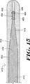
ここで図7を参照すると、図1の実施形態に示す連結部20に類似した連結部120を備えたガイドワイヤ110の部分的な断面図が示されている。連結部120は、重なったテーパー状接合112とチューブ状連結器118とを用い、基端ガイドワイヤ区域114と先端ガイドワイヤ区域116とを接合する。図7の実施形態に示す、基端/先端のガイドワイヤ区域114/116、連結部120、テーパー状接合112、チューブ状連結器118には、図1〜図6Cの実施形態の同じ要素に関して上述したものと同一の全体的な構成、構造、材料、構成方法があってよい。
Referring now to FIG. 7, there is shown a partial cross-sectional view of a
図7の実施形態には更に、先端ガイドワイヤ区域116の先端部分134に配置されたガイドワイヤ110の先端チップ部分130の一例が示されている。先端部分134は、2つのテーパー状領域142,146と2つの一定直径の領域150,154とを有し、そのため端部134はその先端に向かって断面積が小さくなる形状を有する。いくつかの実施形態においては、これらのテーパー142/146及び一定直径の領域150/154は、剛性を移行させ所望の柔軟性特性をもたらすように適合され構成されている。
The embodiment of FIG. 7 further illustrates an example of a
ワイヤまたはリボン158は、先端部分134の先端160に隣接して取り付けられ、先端部分134の先端方向に延びる。いくつかの実施形態においては、ワイヤまたはリボン158は、ワイヤ構造に製造または形成されてもよい。このワイヤ構造は、例えば、以下に更に詳細に述べる実施形態に示されるコイル状ワイヤである。図示の実施形態では、リボン158はほぼ直線のワイヤであり、一定直径の領域154に重なって、取り付け点164に取り付けられている。いくつかの実施形態においては、リボン158は一定直径の区域154に、約0.127センチメートル(0.05インチ)〜約2.540センチメートル(1.0インチ)の範囲の長さで重なっているが、他の実施形態では、重なる長さは更に長くても短くてもよい。
A wire or
リボン158は、任意の適切な材料から構成されてよく、更に、強度や柔軟性の特性などの所望の特性をもたらすために適切な大きさに形成され得る。適切な材料の例には、金属、合金、ポリマーなどがある。いくつかの実施形態においては、リボン158は、金属または合金で形成される。このような合金としては、例えば、ステンレス鋼、ニッケルクロム合金、ニッケルクロム鉄合金、コバルト合金、矯正された超弾性または線形弾性の合金(例えば、ニッケルチタン)ワイヤなどのニッケルチタン合金などである。リボン158は任意の好適な取り付け技術を用いて取り付けられ得る。取り付け技術の例としては、はんだ付け、ろう付け、溶接、接着、圧着などがある。いくつかの実施形態においては、リボンまたはワイヤ158は整形構造または安全構造として機能する。
先端ガイドワイヤ区域116の先端部分134の周囲には、外側のスリーブ168が配置されている。図示の実施形態では、スリーブ168は、基端のテーパー状領域142からリボン158の最も先端の部分を越えて延びており、丸いチップ部分169を形成している。他の実施形態ではスリーブ158は基端方向に更に延びていてもよく、場合によっては連結部120または基端ガイドワイヤ区域114を越えて延びていてもよい。更なる他の実施形態では、スリーブ168はテーパー状領域142の先端の地点から始まっていてもよい。
An
外側のスリーブ168としての使用に適切な材料としては、所望の強度や柔軟性または他の所望の特性をもたらす任意の材料がある。適切な材料には、ポリマーや同様な材料がある。好適なポリマー材料の例としては、ガイドワイヤポリマースリーブとしての使用について一般に既知の幅広い種類のあらゆるポリマーがある。外側のスリーブ168にポリマーを用いることで、幾つかの機能が果たされる。ポリマースリーブを用いることで、先端部分134の柔軟性特性が改善される。スリーブ168のポリマーの選択により、柔軟性が変化する。例えば、デュロメータまたは硬度の低いポリマーは、非常に可撓性または
柔軟なチップを形成する。反対に、デュロメータの高いポリマーは、堅いチップを形成する。スリーブにポリマーを用いることで、ガイドワイヤにはより非外傷性のチップが設けられる。非外傷性のチップは損傷し易い体内の管の通過により適している。最後に、ポリマーは、以下に更に詳細に述べるように放射線不透過材料の固着剤として作用し得る。
Suitable materials for use as the
いくつかの実施形態においては、使用されるポリマー材料は熱可塑性のポリマー材料である。幾つかの適切な材料の例には、ポリウレタン、エラストマーポリアミド、ブロックポリアミド/エーテル(Pebaxなど)、シリコーン、共重合体などがある。スリーブは、単一のポリマー、複数の層、ポリマーの混合物などでよい。材料及び処理技術の選択を慎重に行うことにより、これらの材料の、熱可塑性の変形物、溶剤可溶性の変形物、熱硬化性の変形物が、所望の結果を得るように使用され得る。 In some embodiments, the polymer material used is a thermoplastic polymer material. Examples of some suitable materials include polyurethanes, elastomeric polyamides, block polyamide / ethers (such as Pebax), silicones, copolymers, and the like. The sleeve may be a single polymer, multiple layers, a mixture of polymers, and the like. By careful selection of materials and processing techniques, thermoplastic, solvent-soluble, and thermosetting variants of these materials can be used to achieve the desired results.
スリーブ168は、ガイドワイヤ110の周囲に配置され、使用される特定の材料に適した任意の技術を用いてガイドワイヤ110に取付けられ得る。いくつかの実施形態においては、スリーブ168は、ポリマー材料のスリーブを、該スリーブが先端ガイドワイヤ区域116及びリボン158の周囲に変形されるまで、ある温度に加熱することにより、取付けられる。他の実施形態では、スリーブ168は熱収縮技術を用いて取付けられる場合もある。スリーブ168は、例えば、心なし研削または他の方法により、所望の直径及び滑らかな外面を設けるよう仕上げられる場合がある。
The
いくつかの実施形態においては、ある一定の造影技術、例えば蛍光透視技術を用いた場合にスリーブ168またはその一部をよりはっきり視認できるようにするために、スリーブ168またはその一部は放射線不透過材料を含むか、または放射線不透過材料でドープされていてもよい。当該分野で既知の任意の好適な放射線不透過材料が使用可能である。例としては、貴金属、タングステン、次炭酸バリウム粉末などがあり、更にこれらの混合物もある。いくつかの実施形態においては、スリーブ168には、放射線不透過材料の充填量がそれぞれ異なった別個の区域が備えられていてもよい。例えば、図7では、スリーブ168は先端区域170と基端区域172とを有し、先端区域170の放射線不透過材料の充填のレベルは基端区域172よりも高い。いくつかの実施形態においては、独立した放射線不透過性の部材または一連の放射線不透過性部材、例えば、放射線不透過性のコイル、バンド、チューブ、または他のそのような構造を、ガイドワイヤ110に取り付けるか、あるいは、めっき、引抜き、鍛造、またはイオン注入技術により、心線に組み込むことが考えられる。
In some embodiments, the
更に、いくつかの実施形態においては、スリーブの全体または一部、またはガイドワイヤ110の他の部分に、コーティング、例えば、滑らかな(例えば、親水性の)または他のタイプのコーティングが利用されてもよい。フルオロポリマーなどの疎水性のコーティングは乾燥潤滑性(dry lubricity)をもたらし、これによりガイドワイヤの取り扱いや装置の交換が改善される。滑らかなコーティングは操縦性を改善し、病変を横断する能力を改善する。好適な滑らかなポリマーは、当該分野で周知であり、親水性のポリマー、例えばポリアリーレン酸化物(polyarylene oxide)、ポリビニルピロリドン(polyvinylpyrolidone)、ポリビニルアルコール、ヒドロキシアルキルセルロース誘導体(hydroxy alkyl cellulosic)、アルギン、糖類、カプロラクトン、並びにこれらの混合物及び組み合わせなどであり得る。親水性のポリマーは、好適な潤滑性、接着性および溶解性を備えたコーティングを得るように、そのようなポリマー同士が混合されてもよいし、製剤量の不水溶性化合物(幾つかのポリマーを含む)と混合されてもよい。このコーティング及び材料、並びにこのコーティングを形成するために使用される方法の他の例には、米国特許6,139,510号及び5,772,609号などがあり、これらの特許は参照により本願に組み込まれる。いくつかの実施形態においては、ガイドワイヤの更に先端の部分が上述の親水
性のポリマーで覆われ、更に基端の部分はポリテトラフルオロエチレン(polytetrafluroethylene、PTFE)などのフルオロポリマーで覆われる場合がある。
Further, in some embodiments, a coating, such as a smooth (eg, hydrophilic) or other type of coating, is utilized on all or a portion of the sleeve, or other portions of the
好適な実施形態を構成するために所望の特性に依存して広い範囲の材料、大きさ、および構造が使用可能であることを、当業者などは認識する。先端の構成に関する大きさの以下の例は、限定する意図はなく単に一例として記載するものである。特定の実施形態では、ガイドワイヤは図7で述べた全体的な構造を備え、先端ガイドワイヤ区域116の長さは約25.4センチメートル(10インチ)〜50.8センチメートル(20インチ)の範囲である。先端ガイドワイヤ区域116の主要部分の外径は0.03302センチメートル(0.013インチ)〜約0.03683センチメートル(0.0145インチ)の範囲であり、2つの一定直径の領域150,154の外径はそれぞれ、約0.023876センチメートル(0.0094インチ)〜約0.024638センチメートル(0.0097インチ)の範囲及び0.00254センチメートル(0.001インチ)〜約0.003556センチメートル(0.0014インチ)の範囲である。2つの一定直径の領域150,154の長さはそれぞれ、約10.16センチメートル(4インチ)〜約38.1センチメートル(15インチ)の範囲及び約1.27センチメートル(0.5インチ)〜約10.16センチメートル(4インチ)の範囲である。2つのテーパー状領域142,146の長さはそれぞれ、約1.27センチメートル(0.5インチ)〜約5.08センチメートル(2インチ)の範囲及び約1.27センチメートル(0.5インチ)〜約5.08センチメートル(2インチ)の範囲である。ポリマースリーブ168の外径は、先端ガイドワイヤ区域116の主要部分の外径に適合する大きさであり、例えば0.03302センチメートル(0.013インチ)〜約0.03683センチメートル(0.0145インチ)の範囲である。放射線不透過材料を充填されているポリマースリーブ先端区域170の長さは約2.54センチメートル(1インチ)〜約7.62センチメートル(3インチ)の範囲である。リボン158の長さは、約2.032センチメートル(0.8インチ)〜約5.08センチメートル(2インチ)の範囲であり、実施形態によってはコアの先端方向に約0.508センチメートル(0.2インチ)〜約2.54センチメートル(1インチ)延びていてもよい。
Those skilled in the art will recognize that a wide range of materials, sizes, and structures can be used to construct the preferred embodiment, depending on the desired properties. The following examples of sizes relating to the tip configuration are not intended to be limiting and are merely given as examples. In certain embodiments, the guidewire comprises the overall structure described in FIG. 7 and the length of the
図8は図7で示したガイドワイヤによく似ているガイドワイヤ110を示す。同じ参照数字は上述の同様な構造を示している。図8の実施形態に示す、基端/先端のガイドワイヤ区域114/116、連結部120、テーパー状接合112、およびチューブ状連結器118は、図1〜図7の実施形態の同じ要素に関して上述したものと同一の全体的な構成、構造、材料、および構成の方法を有し得る。
FIG. 8 shows a
図8のガイドワイヤ110の先端チップ部分130も図7で示した先端チップ部分に非常に類似しており、同じ参照数字は同様な構造を示している。しかし図8に示す実施形態では、リボン158がテーパー状領域146に重なるように基端方向に更に延びており、リボン158は2つの取り付け点164,165で取り付けられている。
The
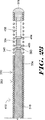
ここで図9を参照すると、図7及び図8の実施形態で示したガイドワイヤに類似した連結部220を備えたガイドワイヤ210の別の実施形態の一部の断面図が示されている。図9の実施形態に示す、基端/先端のガイドワイヤ区域214/216、連結部220、テーパー状接合212、チューブ状連結器218は、図1〜図8の実施形態の同じ要素に関して上述したものと同一の全体的な構成、構造、材料、および構成の方法を有し得る。
Referring now to FIG. 9, there is shown a cross-sectional view of a portion of another embodiment of a
図9の実施形態では、先端ガイドワイヤ区域216の先端部分234に配置されたガイドワイヤ210の先端チップ部分230の別の例が示されている。図7の実施形態のように、先端部分234は、2つのテーパー状領域242,246と、2つの一定直径の領域
250,254とを有し、そのため端部234はその先端に向かって断面積が小さくなる幾何形状を有する。更に、先端チップ部分230はワイヤまたはリボン258を有し、ワイヤまたはリボン258は、先端部分234の先端260に隣接し、取り付け点264で、図7の実施形態で上述した方法と同様な方法で取り付けられている。
In the embodiment of FIG. 9, another example of a
しかし、図9では、先端チップ部分230には、先端ガイドワイヤ区域216の先端部分234の周囲に配置されたスリーブ268とコイル280との組み合わせが設けられている。スリーブ268は基端のテーパー状領域242からガイドワイヤ区域216の先端の基点へと延びている。図示の実施形態では、スリーブ268はテーパー状領域242からテーパー状部分246の中間付近まで延びている。他の実施形態では、スリーブ268は基端に向かって更に延びていてもよく、場合によっては連結部220または基端ガイドワイヤ区域214を越えて延びていてもよい。更なる他の実施形態では、スリーブ268はテーパー状領域242の先端のある地点から始まっていてもよい。
However, in FIG. 9, the
スリーブ268は、同一の材料、構造、放射線不透過性の充填物、コーティングから形成されていてもよいし、これらを含んでもよく、更に図1〜図8に示す実施形態に関して述べた同一の方法に従って形成されて得る。図示の実施形態では、粘着性材料または充填用樹脂279は先端ガイドワイヤ区域216周囲のスリーブ268の先端265に配置されている。しかし、粘着性材料または充填用樹脂279を使用しない別の実施形態もある。
The
コイル280は、スリーブ268の先端265に隣接した粘着性材料279からリボン258の最も先端の部分を越えて延びている。コイル280は、任意の好適な取り付け技術、例えば、はんだ付け、ろう付け、溶接、接着、圧着などを用いて、先端ガイドワイヤ区域216にコイル280の基端281の取り付け点283で取り付けられている。コイル280の先端285は丸いチップ部分269を介してリボン258に取り付けられている。丸いチップ部分269は任意の適切な材料、例えばはんだチップやポリマーチップなどで形成され得る。
The
コイル280は、金属、合金、ポリマーなどの様々な材料で形成され得る。コイルに使用される材料の例には、ステンレス鋼、ニッケルクロム合金、ニッケルクロム鉄合金、コバルト合金、または他の適切な材料などがある。適切な材料の更なる例には、直線の超弾性または線形弾性の合金(例えば、ニッケルチタン)ワイヤ、または代案として、高性能ポリマーなどのポリマー材料がある。いくつかの実施形態においては、コイル280は、放射線不透過材料、例えば、金、白金、タングステン等、またはこれらの合金などで形成され得る。コイル280は、所望の柔軟性を達成する範囲の大きさの丸いまたは平らなリボンから形成されてもよい。いくつかの実施形態においては、コイル280は丸いリボンの場合があり、その直径は約0.00254センチメートル(0.001インチ)〜0.0381センチメートル(0.015インチ)の範囲であり、コイル280の長さは約5.08センチメートル(2インチ)〜約10.16センチメートル(4インチ)の範囲でよい。
The
コイル280は従来の巻回技術によりらせん状に巻回されている。コイル280の隣接する巻回のピッチは、各巻回が後続の巻回に接触し得るように、きつく巻き付けられていてもよいし、あるいはコイル280が開くように、ピッチが設定されていてもよい。図示の実施形態では、コイル280は、コイル280の巻回が基端281では開くように巻かれており、チップ269に隣接している部分ではきつく巻かれている。
The
更に、いくつかの実施形態においては、スリーブ268及びコイル280の一部または全体、またはガイドワイヤ210の他の部分に、上述のコーティングに類似したコーティ
ング、例えば滑らかな(例えば、親水性の)または他のタイプのコーティングが利用されてもよい。
Further, in some embodiments, some or all of the
好適な実施形態を構成するために所望の特性に依存して広い範囲の材料と大きさと構造とが使用可能であることを、当業者などは認識する。図7の参照事項にある先端の構成に関する大きさの例は図9に示す実施形態にも適している。 Those skilled in the art will recognize that a wide range of materials, sizes, and structures can be used to construct the preferred embodiment, depending on the desired properties. The example sizes related to the tip configuration in the reference of FIG. 7 are also suitable for the embodiment shown in FIG.
図10は図9で示したガイドワイヤによく似ているガイドワイヤ210を示し、同じ参照数字は同様な構造を示している。図10の実施形態に示す、基端/先端のガイドワイヤ区域214/216、連結部220、テーパー状接合212、チューブ状連結器218は、図1〜図9の実施形態の同じ要素に関して上述したものと同一の全体的な構成、構造、材料、構成の方法を有し得る。
FIG. 10 shows a
図10のガイドワイヤ210の先端チップ部分230も図9で示した先端チップ部分に非常に類似しており、同じ参照数字は同様な構造を示している。しかし図10に示す実施形態では、リボン258がテーパー状領域246に重なるように基端方向に更に延びており、2つの取り付け点264,283で取り付けられている。
The
ここで図11を参照すると、図7〜図10の実施形態で示したガイドワイヤに類似した連結部320を備えたガイドワイヤ310の別の実施形態の一部の断面図が示されている。図11の実施形態に示す、基端/先端のガイドワイヤ区域314/316、連結部320、テーパー状接合312、チューブ状連結器318は、図1〜図10の実施形態の同じ要素に関して上述したものと同一の全体的な構成、構造、材料、構成の方法を有し得る。
Referring now to FIG. 11, there is shown a cross-sectional view of a portion of another embodiment of a
図11の実施形態には、先端ガイドワイヤ区域316の先端部分334に配置されたガイドワイヤ310の先端チップ部分330の別の例が示されている。図1〜図7の実施形態のように、先端部分334は2つのテーパー状領域342,346と、2つの一定直径の領域350,354を有し、そのため端部334はその先端に向かって断面積が小さくなる形状を有する。更に、先端チップ部分330はワイヤまたはリボン358を備え、図7及び9の実施形態で上述した方法と同様な方法で、取り付け点364で先端部分334の先端360に隣接して取り付けられている。
In the embodiment of FIG. 11, another example of a
しかし、図11では、先端チップ部分330は、二重コイル(dual coil)チップ構成を備え、この構成は、先端ガイドワイヤ区域316の先端部分334の周囲に配置された外側コイル380と内側コイル390とを有する。
However, in FIG. 11, the
図示の実施形態では、外側コイル380は、先端ガイドワイヤ区域316の周囲でテーパー状領域342からリボン358の最も先端の部分を越えて延びている。外側コイル380は、任意の好適な取り付け技術、例えば、はんだ付け、ろう付け、溶接、接着、圧着などを用いて、コイル380の基端381の取り付け点383で先端ガイドワイヤ区域316に取り付けられている。コイル380の先端383は丸いチップ部分369を介してリボン358に取り付けられている。丸いチップ部分369は任意の適切な材料、例えばはんだチップやポリマーチップなどで形成され得る。外側コイル380は、図9及び図10の実施形態で上述したコイル280と同一の材料で形成されていてよく、更にコイル280と同一の全体的な構成及びピッチ間隔が備えられていてよい。いくつかの実施形態においては、外側コイル280は先端方向に取り付け点393を越えて長さ約2〜約4センチメートルの範囲だけ延びていてもよい。
In the illustrated embodiment, the
図示の実施形態では、内側コイル390は、先端ガイドワイヤ区域316の周囲でテーパー状領域346からチップ部分369に隣接したスペーサ要素395まで配置されてい
る。しかし他の実施形態では、スペーサ要素は不要である。コイル390は、任意の好適な取り付け技術、例えば、はんだ付け、ろう付け、溶接、接着、圧着などを用いて、先端ガイドワイヤ区域316に基端391の取り付け点393で取り付けられている。コイル390の先端397はスペーサ要素395に取り付けられている。スペーサ要素395は、リボン358の周囲に配置され、任意の適切な材料、例えば、金属、合金、ポリマーなどで形成され得る。いくつかの実施形態においては、スペーサはポリテトラフルオロエチレン(polytetrafluroethylene、PTFE)などのポリマーで形成されている場合もある。
In the illustrated embodiment, the
内側コイル390は、図9及び図10の実施形態のコイル280に関して上述したものと同一の材料で形成されていてよく、更に同一の全体的な構成及びピッチ間隔を有してもよい。いくつかの実施形態においては、内側コイル390は、外側コイル380を作るために使用したワイヤの直径未満の直径の放射線不透過性のワイヤで形成されている。
The
好適な実施形態を構成するために所望の特性に依存して広い範囲の材料と大きさと構造とが使用可能であることを、当業者などは認識する。図7の参照事項にある先端の構成に関する大きさの例は図9及び図11に示す実施形態にも適している。 Those skilled in the art will recognize that a wide range of materials, sizes, and structures can be used to construct the preferred embodiment, depending on the desired properties. The example sizes related to the tip configuration in the reference of FIG. 7 are also suitable for the embodiments shown in FIGS.
図12は図11で示したガイドワイヤによく類似したガイドワイヤ310を示し、同じ参照数字は同様な構造を示している。図12の実施形態に示す、基端/先端のガイドワイヤ区域314/316、連結部320、テーパー状接合312、チューブ状連結器318は、図1〜図11の実施形態の同じ要素に関して上述したものと同一の全体的な構成、構造、材料、構成の方法を有し得る。
FIG. 12 shows a
図12のガイドワイヤ310の先端チップ部分330も図11で示した先端チップ部分に非常に類似しており、同じ参照数字同様な構造を示している。しかし図12に示す実施形態では、リボン358がテーパー状領域346に重なるよう基端方向に更に延びており、2つの取り付け点364,393で取り付けられている。
The
ここで図13〜図21を参照すると、ガイドワイヤに使用するための一連の代替のチップ設計が示され、これらの設計には、安全及び/又は整形構造として使用するための、ワイヤまたはリボンがコイル状またはらせん状に形成された部分がある。コイル状またはらせん状に形成された安全構造または整形構造を用いているこれらのチップ設計は、広い範囲のガイドワイヤ構造に使用可能である。例えば、これらのチップ設計は、上述の連結構造などの本願で開示した他の構造と組み合わせて使用されてもよいし、これらの連結構造を有さないガイドワイヤなどの他のガイドワイヤ構成で使用されてもよい。 Referring now to FIGS. 13-21, a series of alternative tip designs for use with guidewires are shown, which include wires or ribbons for use as safety and / or shaping structures. There is a portion formed in a coil shape or a spiral shape. These tip designs using a safety or shaping structure formed in a coil or spiral can be used for a wide range of guidewire structures. For example, these chip designs may be used in combination with other structures disclosed in this application, such as the connection structures described above, or used in other guidewire configurations, such as guidewires that do not have these connection structures. May be.
ここで図13を参照すると、コイル状の安全及び/又は整形構造458を備えたガイドワイヤ410の1つの実施形態が示されている。ガイドワイヤ410には先端部分416を備えたコア部材413がある。コア部材413及びコア部材413の先端部分416は、ガイドワイヤの一部について上に開示した構造を有してもよいし、ガイドワイヤで使用される当該分野で一般に既知の他の構造を有してもよい。更に、コア部材413及びコア部材413の先端部分416は、ガイドワイヤ部材またはガイドワイヤ区域を形成する際に使用される上述の任意の適切な材料を用いて形成されていてもよいし、ガイドワイヤで使用される当該分野で一般に既知の他の材料を含んでいてもよい。図示の実施形態では、コア部材413の先端部分416は中実のワイヤである。該ワイヤは、3つの一定直径の部分450,452,454と、2つのテーパー状部分442,446とを備えたチップ部分434を備えている。
Referring now to FIG. 13, one embodiment of a
心線413の一部分の周囲に配置されているのは、コイル状の安全及び/又は整形構造
458、例えば、コイル状リボン、コイル状ワイヤ、または他のこのようなコイル状構造である。図示の実施形態では、コイル状構造458は、コイル状リボンであり、最も先端にあるテーパー状部分446の一部及び最も先端にある一定直径の部分454に重なるか、またはこの部分を囲み、更に心線413の先端460から先端方向に延びている。
Disposed around a portion of the
コイル458は、強度や柔軟性の特性などの所望の特性をもたらすために、任意の適切な材料から構成され、適切な大きさに形成され得る。いくつかの実施形態においては、コイル458が心線413に取り付けられることによって、コイル458が重なっている部分の心線413の特性が影響を受ける場合もある。
The
コイル458に使用される材料の例には、ステンレス鋼、ニッケルクロム合金、ニッケルクロム鉄合金、コバルト合金、ニッケルチタン合金、または他の適切な材料などがある。適切な材料の更なる例には、直線の超弾性または線形弾性の合金(例えば、ニッケルチタン)、または代案として、高性能ポリマーなどのポリマー材料がある。いくつかの実施形態においては、コイル458は、放射線不透過材料、例えば、金、白金、タングステンなど、またはこれらの合金などで形成され得る。コイル458は、所望の柔軟性を達成する範囲の大きさの丸いまたは平らなリボンで形成されていてもよい。いくつかの実施形態においては、コイル458は丸いリボンの場合があり、その直径は約0.00254センチメートル(0.001インチ)〜0.0381センチメートル(0.015インチ)の範囲である。他の実施形態では、コイルは平らまたは長方形に形成されたリボンで形成されていてもよく、このリボンの幅は約0.00508センチメートル(0.002インチ)〜約0.0508センチメートル(0.02インチ)の範囲であり、このリボンの厚さは約0.00127センチメートル(0.0005インチ)〜約0.0508センチメートル(0.02インチ)の範囲である。
Examples of materials used for the
コイル458は任意の好適な取り付け技術を用いて心線413に取り付けられていてよい。取り付け技術の例には、はんだ付け、ろう付け、溶接、接着、圧着などがある。図示の実施形態では、コイル458は2つの取り付け点464及び465で取り付けられている。
The
コイル458は従来の巻き付け技術によりらせん状に巻かれている。コイル458は、各巻回が後続の巻回に接触するように、隣接する巻回のピッチがきつく巻かれてもよいし、あるいは、コイル458が開くような方法で巻かれるようにピッチが設定されていてもよい。いくつかの実施形態においては、コイルのピッチは約1.016センチメートル(0.4インチ)までであり、実施形態によってはピッチは約0.2032センチメートル(0.08インチ)までであり、実施形態によってはピッチの範囲は約0.0254センチメートル(0.01インチ)〜約0.2032センチメートル(0.08インチ)である。ピッチは、コイル458の長さ全体を通じて一定でもよいし、柔軟性などの所望の特性に依存して変化していてもよい。いくつかの実施形態においては、心線413と重なっているコイル458部分のピッチは狭く、心線413と重なっていないコイル部分のピッチは広い。例えば、いくつかの実施形態においては、心線413と重なっているコイル部分のピッチは約0.0254センチメートル(0.01インチ)〜約0.2032センチメートル(0.08インチ)の範囲、例えば、0.1016センチメートル(0.04インチ)であり、心線413と重なっていないコイル部分のピッチは約0.2032センチメートル(0.08インチ)までである。コイルピッチのこれらの変化は、ワイヤを最初に巻いている間に達成されてもよいし、巻き終わってからまたはガイドワイヤに取り付けられた後でコイルを操作することにより達成されてもよい。例えば、いくつかの実施形態においては、コイル458をガイドワイヤに取り付けた後で、単純にコイルを引っ張ることでコイルの先端部分に広いピッチが達成されてもよい。
The
コイル458の直径は、心線413の先端部分の周囲に嵌合して、同先端部分と組み合って、所望の特性をもたらすような大きさにされていることが望ましい。コイル458の直径は一定でもよいしテーパー状をなしてもよい。いくつかの実施形態においては、コイル458は心線413のテーパー状の区域に連結するよう先細っている。コイル458の直径は、所望により、心線413の先端より先にテーパー状部分を有してもよい。
The diameter of the
ガイドワイヤ410の先端部分416の周囲には、外側のスリーブ468が配置されている。図示の実施形態では、スリーブ468は、コイル状リボン458の最も先端の部分を越えて延びており、丸いチップ部分469を形成している。スリーブ468は、スリーブ構造に関して上述した構造を備えていてもよいし、スリーブ構造に関して上述した材料及び方法で形成されていてもよい。
An
好適な実施形態を構成するために、所望の特性に応じて、広い範囲の材料、大きさ、および構造が使用可能であることを、当業者などは認識する。以下の例は、限定する意図はなく単に一例として記載されている。特定の実施形態では、ガイドワイヤには図13で述べた全体的な構造があり、心線413は線形弾性のニッケルチタン合金で形成された心線の先端部分であり、一定直径の部分450,452,454の直径はそれぞれ、約0.024638センチメートル(0.0097インチ)、約0.01524センチメートル(0.006インチ)、約0.00762センチメートル(0.003インチ)である。更に、一定直径の部分452及び454の長さはそれぞれ約2.54センチメートル(1インチ)及び約1.27センチメートル(0.5インチ)である。テーパー状部分442,446はそれぞれ約2.54センチメートル(1インチ)及び約3.81センチメートル(1.5インチ)である。コイル458は、長さ約3.81センチメートル(1.5インチ)であり、平らなステンレス鋼ワイヤで形成されており、その大きさは幅約0.0127センチメートル(約0.005インチ)、厚さ約0.00254センチメートル(0.001インチ)である。コイル458の直径はコイル458の基端の約0.024638センチメートル(0.0097インチ)からコイル458の先端の約0.00762センチメートル(0.003インチ)へと先細っており、コイル458は心線413に取り付け点464,465ではんだを用いて取り付けられている。コイル458が心線413と重なるのは約2.794センチメートル(1.1インチ)、心線413より先端方向に延びているのは約1.016センチメートル(0.4インチ)である。心線と重なっているコイル部分のピッチは約0.1016センチメートル(0.04インチ)であり、心線の先端方向に延びているコイル部分のピッチは約0.2032センチメートル(0.08インチ)である。このような実施形態では、コイル458が心線413と約2.794センチメートル(1.1インチ)重なっている部分のガイドワイヤは、めっきされており、例えば、すずめっきされている。スリーブ468は、心線413及びコイル458の周囲に取り付けられたポリウレタンスリーブである。スリーブ468上には親水性のコーティングが施されている。
Those skilled in the art will recognize that a wide range of materials, sizes, and structures can be used, depending on the desired properties, to construct a preferred embodiment. The following examples are not intended to be limiting and are described merely as examples. In a particular embodiment, the guidewire has the overall structure described in FIG. 13, where the
ここで図14を参照すると、図13に示すチップ構成に似たチップ構成を備えたガイドワイヤ410が示されており、同じ参照数字は同様な構造を示している。しかし図13の実施形態の心線413のチップ部分434にあるのは1つの一定直径の部分450と1つのテーパー状部分442であり、コイル状リボン458はテーパー状部分442の一部の周囲に取り付けられている。図14に示す実施形態の他の態様及び構成要素には、図13に関して上述したものと同一の全体的な構造及び材料があってよい。
Referring now to FIG. 14, a
特定の実施形態では、ガイドワイヤ413は、図14で述べた全体的な構造を有する。心線413は、線形弾性のニッケルチタン合金で形成された心線の先端部分である。一定直径の部分450の直径は約0.024638センチメートル(0.0097インチ)であり、テーパー状部分442の長さは約7.62センチメートル(3インチ)であり、直
径約0.00762センチメートル(0.003インチ)のテーパー状部分442の先端で終端する。コイル458は、長さ約3.81センチメートル(1.5インチ)であり、平らなステンレス鋼ワイヤで形成されており、その大きさは幅約0.0127センチメートル(約0.005インチ)、厚さ約0.00254センチメートル(0.001インチ)である。コイル458の直径は、コイル458の基端の約0.024638センチメートル(0.0097インチ)からコイル458の先端の約0.00762センチメートル(0.003インチ)へと先細っている。コイル458は心線413に取り付け点464,465ではんだを用いて取り付けられている。コイル458が心線413と重なるのは約2.794センチメートル(1.1インチ)、心線413より先端方向に延びているのは約1.016センチメートル(0.4インチ)である。心線と重なっているコイル部分のピッチは約0.1016センチメートル(0.04インチ)であり、心線の先端方向に延びているコイル部分のピッチは約0.2032センチメートル(0.08インチ)である。このような実施形態では、コイル458が心線413と約2.794センチメートル(1.1インチ)重なっている部分のガイドワイヤはめっきされている場合があり、例えば、すずめっきされていたりする。スリーブ468は、心線413及びコイル458の周囲に取り付けられたポリウレタンスリーブである。スリーブ468上には親水性のコーティングが施されている。
In certain embodiments, guidewire 413 has the overall structure described in FIG. The
ここで図15を参照すると、図13に示すチップ構成に似たチップ構成を備えたガイドワイヤ410が示されており、同じ参照数字は同様な構造を示している。しかし、図15の実施形態の心線413のチップ部分434は、2つの一定直径の部分450,454と、1つのテーパー状部分442を有する。コイル458は一定直径の部分454の周囲に取り付けられている。図15では、コイル458は、一定直径の部分454の周囲に2つの取り付け点464,465で取り付けられており、テーパー状ではなく、コイル458の長さに沿う実質的なピッチの変化はない。図15に示す実施形態の他の態様及び構成要素には、図13に関して上述したものと同一の全体的な構造及び材料があってよい。
Referring now to FIG. 15, a
ここで図16を参照すると、図15に示すチップ構成に似たチップ構成を備えたガイドワイヤ410が示されており、同じ参照数字は同様な構造を示している。しかし図16の実施形態では、取り付け点464より先端側のコイル458のピッチは取り付け点464より基端側のコイル458のピッチと比べ長い。図16に示す実施形態の他の態様及び構成要素には、図13に関して上述したものと同一の全体的な構造及び材料があってよい。
Referring now to FIG. 16, a
ここで図17を参照すると、図16に示すチップ構成に似たチップ構成を備えたガイドワイヤ410が示されており、同じ参照数字は同様な構造を示している。しかし図17の実施形態では、心線413の先端に近い取り付け点464のみが使用されている。図17に示す実施形態の他の態様及び構成要素は、図13に関して上述したものと同一の全体的な構造及び材料を有し得る。
Referring now to FIG. 17, there is shown a
ここで図18を参照すると、図16に示すチップ構成に似たチップ構成を備えたガイドワイヤ410が示されており、同じ参照数字は同様な構造を示している。しかし図18の実施形態では、最も基端側にある取り付け点465のみが使用されている。図18に示す実施形態の他の態様及び構成要素は、図13に関して上述したものと同一の全体的な構造及び材料を有し得る。
Referring now to FIG. 18, a
ここで図19を参照すると、図16に示すチップ構成に似たチップ構成を備えたガイドワイヤ410が示されており、同じ参照数字は同様な構造を示している。しかし図19の実施形態では、安全及び/又は整形構造458は、一定直径の部分454の周囲に巻き付けられたコイル状部分490を備え、心線413の先端から先端方向に延びた非コイル状部分492へと変形している。図18に示す実施形態の他の態様及び構成要素は、図13
に関して上述したものと同一の全体的な構造及び材料を有し得る。
Referring now to FIG. 19, a
May have the same overall structure and materials as described above with respect to.
ここで図20を参照すると、図19に示すチップ構成に似たチップ構成を備えたガイドワイヤ410が示されており、同じ参照数字は同様な構造を示している。しかし図20の実施形態では、安全及び/又は整形構造458には2つの独立した部分がある。この2つの独立した部分は、一定直径の部分454と重なり心線413の先端から先端方向に延びた概ね直線の部分492と、直線部分492を一定直径の部分454に取り付けるために直線リボン部分492及び一定直径の部分454の双方の周囲に巻き付けられたコイル状部分490である。図18に示す実施形態の他の態様及び構成要素は、図13に関して上述したものと同一の全体的な構造及び材料を有し得る。
Referring now to FIG. 20, a
ここで図21を参照すると、図21は図19に示すチップ構成に似たガイドワイヤ410のチップ構成の部分断面図であり、同じ参照数字は同様な構造を示している。図19の実施形態と同じように、図21に示す実施形態も、安全及び/又は整形構造458を有し、この構造は一定直径の部分454の周囲に巻き付けられたコイル状部分490を有する。更に安全及び/又は整形構造458は、心線413の先端から先端方向に延びた非コイル状部分492へと変形している。しかし、図21では、非コイル状部分492は、らせん状ワイヤを形成するように、ねじられている。図21に示す実施形態の他の態様及び構成要素は、図13に関して上述したものと同一の全体的な構造及び材料を有し得る。
Referring now to FIG. 21, FIG. 21 is a partial cross-sectional view of a tip configuration of a
ここで図22を参照すると、図22は図9及び図10に示すガイドワイヤ210の先端チップ部分230に似たチップ構成を備えたガイドワイヤ410の部分断面図であり、同じ参照数字は同様な構造を示している。しかし図22の実施形態では、チップ構成に備えられているのは、図9及び図10に示す非コイル状リボン258ではなく、コイル状の安全及び/又は整形構造458である。コイルは、例えばはんだ付けにより、2つの取り付け点464,465でガイドワイヤに取り付けられている。図21に示す実施形態の他の態様及び構成要素は、図9及び図10に関して及び/又は図13に関して上述したものと同一の全体的な構造及び材料を有し得る。
Referring now to FIG. 22, FIG. 22 is a partial cross-sectional view of a
ここで図23を参照すると、図23は図11及び図12に示すガイドワイヤ210の先端チップ部分230に似たチップ構成を備えたガイドワイヤ410の部分断面図であり、同じ参照数字は同様な構造を示している。しかし図23の実施形態では、チップ構成に備えられているのは、図11及び図12に示す非コイル状構造258ではなく、コイル状の安全及び/又は整形構造458である。コイルは、例えば、はんだ付けにより、2つの取り付け点464,465でガイドワイヤに取り付けられている。更に、図21の実施形態は、図11及び図12に示す内側コイル390及びスペーサ395を有さない。図21に示す実施形態の他の態様及び構成要素は、図11及び図12に関して及び/又は図13に関して上述したものと同一の全体的な構造及び材料を有し得る。
Referring now to FIG. 23, FIG. 23 is a partial cross-sectional view of a
本開示が多くの点で単なる一例に過ぎないことが理解されるべきである。細部に亘り、特に、形状、寸法、工程の配列について、本発明の範囲を逸脱することなく変形がなされてよい。例えば、ガイドワイヤの基端区域と先端区域との連結には代替の構造が使用されてよい。更に、代替のチップ構成、例えば柔軟なコイルチップ、ポリマー外被チップ、コイル状の安全及び/又は成形ワイヤを備えたチップ、およびこれらの組み合わせ、及び、他のこのような構造が、ガイドワイヤに配置されてもよい。本発明の範囲は、もちろん、添付の特許請求の範囲が示される文言で定義されている。 It should be understood that the present disclosure is merely an example in many respects. Changes may be made in details, particularly with respect to shape, dimensions, and sequence of steps, without departing from the scope of the invention. For example, alternative structures may be used to connect the proximal and distal sections of the guidewire. In addition, alternative tip configurations, such as flexible coil tips, polymer jacket tips, tips with coiled safety and / or molded wires, and combinations thereof, and other such structures, can be used with guidewires. It may be arranged. The scope of the invention is, of course, defined by the language in which the appended claims are presented.
Claims (10)
ステンレス鋼からなる基端区域と、前記基端区域は先端を有し、前記基端区域の前記先端は柔軟性移行領域を有することと、
線形弾性ニッケルチタン合金からなる先端区域と、前記先端区域は基端を有し、前記先端区域の前記基端は柔軟性移行領域を有することと、
前記基端区域の前記先端及び前記先端区域の前記基端に隣接して配置されている連結器とを備えており、前記連結器は、ステンレス鋼とニッケルチタン合金との双方を溶接するのに好適である、ニッケルクロムモリブデン合金、C276合金、又はB2合金からなり、前記基端区域を前記先端区域に接合するように適合され構成されている、ガイドワイヤ。A guide wire,
A proximal section made of stainless steel, the proximal section has a tip, and the tip of the proximal section has a flexible transition region;
A tip section made of a linear elastic nickel titanium alloy, the tip section having a proximal end, and the proximal end of the tip section having a flexible transition region;
And a connector disposed adjacent to the proximal end of the proximal section and the proximal section of the distal section, the coupler for welding both stainless steel and nickel titanium alloy. A guide wire comprising a nickel chrome molybdenum alloy, a C276 alloy, or a B2 alloy that is suitable and adapted to join the proximal section to the distal section.
第1の柔軟性を備え、ステンレス鋼からなる基端区域と、
第2の柔軟性を備え、線形弾性ニッケルチタン合金からなる先端区域と、
前記第1の柔軟性から前記第2の柔軟性に移行するように前記基端区域を前記先端区域と接合する手段とを備えており、前記手段は、ステンレス鋼とニッケルチタン合金との双方を溶接するのに好適である、ニッケルクロムモリブデン合金、C276合金、又はB2合金からなる連結器を用いる、ガイドワイヤ。A guide wire,
A proximal section made of stainless steel with a first flexibility;
A tip section having a second flexibility and made of a linear elastic nickel titanium alloy;
Means for joining the proximal section with the distal section so as to transition from the first flexibility to the second flexibility, the means comprising both stainless steel and a nickel titanium alloy. Guide wire using a coupler made of nickel chrome molybdenum alloy, C276 alloy or B2 alloy, suitable for welding.
Applications Claiming Priority (3)
| Application Number | Priority Date | Filing Date | Title |
|---|---|---|---|
| US09/972,276 US6918882B2 (en) | 2001-10-05 | 2001-10-05 | Guidewire with stiffness blending connection |
| US10/086,992 US7074197B2 (en) | 2001-10-05 | 2002-02-28 | Composite guidewire |
| PCT/US2002/031959 WO2003030982A2 (en) | 2001-10-05 | 2002-10-04 | Composite guidewire |
Related Child Applications (1)
| Application Number | Title | Priority Date | Filing Date |
|---|---|---|---|
| JP2009127759A Division JP5254129B2 (en) | 2001-10-05 | 2009-05-27 | Composite guidewire |
Publications (2)
| Publication Number | Publication Date |
|---|---|
| JP2005528126A JP2005528126A (en) | 2005-09-22 |
| JP4494782B2 true JP4494782B2 (en) | 2010-06-30 |
Family
ID=26775392
Family Applications (1)
| Application Number | Title | Priority Date | Filing Date |
|---|---|---|---|
| JP2003534012A Expired - Lifetime JP4494782B2 (en) | 2001-10-05 | 2002-10-04 | Composite guidewire |
Country Status (7)
| Country | Link |
|---|---|
| US (3) | US7618379B2 (en) |
| EP (1) | EP1432467B1 (en) |
| JP (1) | JP4494782B2 (en) |
| AT (1) | ATE312640T1 (en) |
| CA (1) | CA2462335C (en) |
| DE (1) | DE60208057T2 (en) |
| WO (1) | WO2003030982A2 (en) |
Cited By (1)
| Publication number | Priority date | Publication date | Assignee | Title |
|---|---|---|---|---|
| US11202888B2 (en) | 2017-12-03 | 2021-12-21 | Cook Medical Technologies Llc | MRI compatible interventional wireguide |
Families Citing this family (123)
| Publication number | Priority date | Publication date | Assignee | Title |
|---|---|---|---|---|
| US20030009208A1 (en) | 2001-07-05 | 2003-01-09 | Precision Vascular Systems, Inc. | Torqueable soft tip medical device and method of usage |
| ATE312640T1 (en) | 2001-10-05 | 2005-12-15 | Boston Scient Ltd | COMPOSITE GUIDE WIRE |
| US7914467B2 (en) * | 2002-07-25 | 2011-03-29 | Boston Scientific Scimed, Inc. | Tubular member having tapered transition for use in a medical device |
| JP4138583B2 (en) | 2002-08-08 | 2008-08-27 | テルモ株式会社 | Guide wire |
| JP4138582B2 (en) | 2002-08-23 | 2008-08-27 | テルモ株式会社 | Guide wire |
| US6866642B2 (en) * | 2002-11-25 | 2005-03-15 | Advanced Cardiovascular Systems, Inc. | Enhanced method for joining two core wires |
| US7153277B2 (en) * | 2002-12-03 | 2006-12-26 | Scimed Life Systems, Inc. | Composite medical device with markers |
| US7077811B2 (en) * | 2002-12-23 | 2006-07-18 | Scimed Life Systems, Inc. | Guidewire tip construction |
| US8377035B2 (en) | 2003-01-17 | 2013-02-19 | Boston Scientific Scimed, Inc. | Unbalanced reinforcement members for medical device |
| US8113916B2 (en) * | 2003-01-17 | 2012-02-14 | Boston Scientific Scimed, Inc. | Straightening and centerless grinding of wire for use with medical devices |
| US20040167441A1 (en) * | 2003-02-26 | 2004-08-26 | Reynolds Brian R. | Composite medical device |
| US7824345B2 (en) | 2003-12-22 | 2010-11-02 | Boston Scientific Scimed, Inc. | Medical device with push force limiter |
| WO2005118047A1 (en) | 2004-06-04 | 2005-12-15 | Radi Medical Systems Ab | Sensor and guide wire assembly |
| SE0401431D0 (en) * | 2004-06-04 | 2004-06-04 | Radi Medical Systems | Sensor and guide wire assembly |
| JP2006122311A (en) * | 2004-10-28 | 2006-05-18 | Tokusen Kogyo Co Ltd | Guide wire |
| JP2006263083A (en) * | 2005-03-23 | 2006-10-05 | Tokusen Kogyo Co Ltd | Medical guide wire |
| JP2006271677A (en) * | 2005-03-29 | 2006-10-12 | Tokusen Kogyo Co Ltd | Medical guidewire |
| JP5066698B2 (en) * | 2005-06-02 | 2012-11-07 | テルモ株式会社 | MEDICAL DEVICE HAVING POLYIMIDE FILM AND PROCESS FOR PRODUCING THE SAME |
| US9636115B2 (en) * | 2005-06-14 | 2017-05-02 | Stryker Corporation | Vaso-occlusive delivery device with kink resistant, flexible distal end |
| US8267872B2 (en) * | 2005-07-07 | 2012-09-18 | St. Jude Medical, Cardiology Division, Inc. | Steerable guide wire with torsionally stable tip |
| US20070185415A1 (en) * | 2005-07-07 | 2007-08-09 | Ressemann Thomas V | Steerable guide wire with torsionally stable tip |
| US7850623B2 (en) | 2005-10-27 | 2010-12-14 | Boston Scientific Scimed, Inc. | Elongate medical device with continuous reinforcement member |
| US8152742B2 (en) * | 2006-05-01 | 2012-04-10 | Boston Scientific Scimed, Inc. | Crossing guide wire with corrugated shaping ribbon |
| EP2079506B1 (en) * | 2006-09-13 | 2016-05-25 | Boston Scientific Limited | Crossing guidewire |
| JP4277117B2 (en) * | 2007-03-29 | 2009-06-10 | 福井県 | Dissimilar metal joined body of nickel / titanium alloy material and pure titanium material and joining method thereof |
| US8409114B2 (en) | 2007-08-02 | 2013-04-02 | Boston Scientific Scimed, Inc. | Composite elongate medical device including distal tubular member |
| US8105246B2 (en) | 2007-08-03 | 2012-01-31 | Boston Scientific Scimed, Inc. | Elongate medical device having enhanced torque and methods thereof |
| US8821477B2 (en) | 2007-08-06 | 2014-09-02 | Boston Scientific Scimed, Inc. | Alternative micromachined structures |
| US9808595B2 (en) | 2007-08-07 | 2017-11-07 | Boston Scientific Scimed, Inc | Microfabricated catheter with improved bonding structure |
| US20090118675A1 (en) * | 2007-11-02 | 2009-05-07 | Boston Scientific Scimed, Inc. | Elongate medical device with a shapeable tip |
| US7841994B2 (en) | 2007-11-02 | 2010-11-30 | Boston Scientific Scimed, Inc. | Medical device for crossing an occlusion in a vessel |
| US7871414B2 (en) * | 2007-12-28 | 2011-01-18 | Wilson-Cook Medical Inc. | Loop tip wire guide with outer sleeve |
| US8376961B2 (en) | 2008-04-07 | 2013-02-19 | Boston Scientific Scimed, Inc. | Micromachined composite guidewire structure with anisotropic bending properties |
| US8002715B2 (en) * | 2008-05-30 | 2011-08-23 | Boston Scientific Scimed, Inc. | Medical device including a polymer sleeve and a coil wound into the polymer sleeve |
| US8535243B2 (en) | 2008-09-10 | 2013-09-17 | Boston Scientific Scimed, Inc. | Medical devices and tapered tubular members for use in medical devices |
| EP2376171B1 (en) * | 2008-12-10 | 2018-04-25 | Microvention, Inc. | Microcatheter |
| US8795254B2 (en) | 2008-12-10 | 2014-08-05 | Boston Scientific Scimed, Inc. | Medical devices with a slotted tubular member having improved stress distribution |
| US8444577B2 (en) * | 2009-01-05 | 2013-05-21 | Cook Medical Technologies Llc | Medical guide wire |
| AU2010225987B2 (en) | 2009-03-19 | 2015-09-03 | Japan Lifeline Co., Ltd. | Medical guide wire |
| JP5280263B2 (en) * | 2009-03-25 | 2013-09-04 | 日本ライフライン株式会社 | Guide wire |
| JP2010259624A (en) * | 2009-05-07 | 2010-11-18 | Hi-Lex Corporation | Guide wire and manufacturing method thereof |
| EP2433668B1 (en) | 2009-05-20 | 2014-01-22 | Japan Lifeline Co., Ltd. | Medical guide wire |
| JP5013547B2 (en) | 2009-06-16 | 2012-08-29 | 朝日インテック株式会社 | Medical guidewire |
| JP4913198B2 (en) * | 2009-10-27 | 2012-04-11 | 株式会社パテントストラ | Medical guide wire, method for manufacturing medical guide wire, assembly of medical guide wire, microcatheter and guiding catheter, and assembly of medical guide wire, balloon catheter and guiding catheter |
| US8137293B2 (en) | 2009-11-17 | 2012-03-20 | Boston Scientific Scimed, Inc. | Guidewires including a porous nickel-titanium alloy |
| US8569625B2 (en) | 2009-12-22 | 2013-10-29 | W. C. Heraeus Gmbh | Joined dissimilar materials |
| US20110160680A1 (en) * | 2009-12-29 | 2011-06-30 | Cook Incorporated | Wire guide with cannula |
| JP2013523282A (en) | 2010-03-31 | 2013-06-17 | ボストン サイエンティフィック サイムド,インコーポレイテッド | Guide wire with bending stiffness profile |
| US8487210B2 (en) | 2010-06-11 | 2013-07-16 | W. C. Hereaus GmbH | Joined dissimilar materials and method |
| CA2808202C (en) | 2010-11-09 | 2013-11-05 | Opsens Inc. | Guidewire with internal pressure sensor |
| US11298251B2 (en) | 2010-11-17 | 2022-04-12 | Abbott Cardiovascular Systems, Inc. | Radiopaque intraluminal stents comprising cobalt-based alloys with primarily single-phase supersaturated tungsten content |
| JP5382953B2 (en) * | 2011-01-28 | 2014-01-08 | 朝日インテック株式会社 | Guide wire |
| EP2670470B1 (en) | 2011-02-04 | 2019-04-24 | Boston Scientific Scimed, Inc. | Guidewires |
| US20120209176A1 (en) | 2011-02-09 | 2012-08-16 | Boston Scientific Scimed, Inc. | Balloon catheter |
| CN103648575B (en) | 2011-02-25 | 2016-10-26 | 微排放器公司 | The foley's tube strengthened |
| JP5929315B2 (en) * | 2011-02-28 | 2016-06-01 | 住友ベークライト株式会社 | Medical device and method for manufacturing medical device |
| US8585643B2 (en) | 2011-03-07 | 2013-11-19 | Stryker Corporation | Balloon catheter and method of manufacture |
| JP2012200291A (en) * | 2011-03-23 | 2012-10-22 | Asahi Intecc Co Ltd | Guidewire |
| US9072874B2 (en) | 2011-05-13 | 2015-07-07 | Boston Scientific Scimed, Inc. | Medical devices with a heat transfer region and a heat sink region and methods for manufacturing medical devices |
| JP5382881B2 (en) * | 2011-06-15 | 2014-01-08 | 朝日インテック株式会社 | Guide wire |
| US9724494B2 (en) * | 2011-06-29 | 2017-08-08 | Abbott Cardiovascular Systems, Inc. | Guide wire device including a solderable linear elastic nickel-titanium distal end section and methods of preparation therefor |
| US20130046286A1 (en) * | 2011-08-17 | 2013-02-21 | Abbott Cardiovascular Systems | Narrow hysteresis ni-ti core wire for enhanced guide wire steering response |
| JP2013094339A (en) * | 2011-10-31 | 2013-05-20 | Asahi Intecc Co Ltd | Guide wire |
| JP5370974B2 (en) * | 2011-12-16 | 2013-12-18 | 朝日インテック株式会社 | Medical guidewire |
| US9061088B2 (en) * | 2012-02-02 | 2015-06-23 | Abbott Cardiovascular Systems, Inc. | Guide wire core wire made from a substantially titanium-free alloy for enhanced guide wire steering response |
| US10029076B2 (en) | 2012-02-28 | 2018-07-24 | Covidien Lp | Intravascular guidewire |
| JP6104884B2 (en) * | 2012-03-16 | 2017-03-29 | テルモ株式会社 | Guide wire |
| US9592135B2 (en) | 2012-04-26 | 2017-03-14 | Medtronic Vascular, Inc. | Radiopaque enhanced cobalt alloy for stents |
| US9339398B2 (en) | 2012-04-26 | 2016-05-17 | Medtronic Vascular, Inc. | Radiopaque enhanced nickel alloy for stents |
| US9174309B2 (en) * | 2012-07-24 | 2015-11-03 | General Electric Company | Turbine component and a process of fabricating a turbine component |
| EP2887863B1 (en) | 2012-08-27 | 2019-11-27 | Boston Scientific Scimed, Inc. | Pressure-sensing medical device system |
| CN104619247B (en) | 2012-09-17 | 2017-10-27 | 波士顿科学西美德公司 | Pressure-sensing seal wire |
| US20140121642A1 (en) | 2012-10-25 | 2014-05-01 | Boston Scientific Scimed, Inc. | Dual function medical devices |
| US9248255B2 (en) | 2012-11-14 | 2016-02-02 | Biosense Webster (Israel) Ltd. | Catheter with improved torque transmission |
| EP2922593B1 (en) * | 2012-11-21 | 2020-04-08 | Concert Medical, LLC | Preformed guidewire |
| US9636485B2 (en) | 2013-01-17 | 2017-05-02 | Abbott Cardiovascular Systems, Inc. | Methods for counteracting rebounding effects during solid state resistance welding of dissimilar materials |
| WO2014149688A1 (en) | 2013-03-15 | 2014-09-25 | Boston Scientific Scimed, Inc. | Pressure sensing guidewire |
| EP2999400B1 (en) | 2013-05-22 | 2022-08-03 | Boston Scientific Scimed, Inc. | Pressure sensing guidewire systems including an optical connector cable |
| CN105578952B (en) | 2013-07-26 | 2019-03-19 | 波士顿科学国际有限公司 | Minimize the FFR sensing head design of the pressure unbalance loading as caused by stress |
| CN105636508B (en) | 2013-08-14 | 2019-09-27 | 波士顿科学国际有限公司 | Medical instrument system including tapered core fibre |
| US9775523B2 (en) | 2013-10-14 | 2017-10-03 | Boston Scientific Scimed, Inc. | Pressure sensing guidewire and methods for calculating fractional flow reserve |
| WO2015142623A1 (en) | 2014-03-18 | 2015-09-24 | Boston Scientific Scimed, Inc. | Pressure sensing guidewires |
| CN106456277B (en) | 2014-04-17 | 2020-03-27 | 波士顿科学国际有限公司 | Self-cleaning optical connector |
| JP6586425B2 (en) * | 2014-04-21 | 2019-10-02 | コーニンクレッカ フィリップス エヌ ヴェKoninklijke Philips N.V. | Intravascular device, system and method having separate sections with core elements engaged |
| WO2015187385A1 (en) | 2014-06-04 | 2015-12-10 | Boston Scientific Scimed, Inc. | Pressure sensing guidewire systems with reduced pressure offsets |
| ES2686826T3 (en) | 2014-07-18 | 2018-10-22 | Stryker Corporation | Manufacturing method of coated tubular support members |
| US9782129B2 (en) | 2014-08-01 | 2017-10-10 | Boston Scientific Scimed, Inc. | Pressure sensing guidewires |
| WO2016028486A1 (en) | 2014-08-21 | 2016-02-25 | Boston Scientific Scimed, Inc. | Medical device with support member |
| JP6245760B2 (en) * | 2014-09-16 | 2017-12-13 | 朝日インテック株式会社 | Guide wire |
| JP6313183B2 (en) * | 2014-10-09 | 2018-04-18 | 朝日インテック株式会社 | Guide wire |
| JP6550463B2 (en) | 2014-12-05 | 2019-07-24 | ボストン サイエンティフィック サイムド,インコーポレイテッドBoston Scientific Scimed,Inc. | Medical device for pressure sensing and method of manufacturing the same |
| US10071229B2 (en) | 2015-04-14 | 2018-09-11 | Abbott Cardiovascular Systems, Inc. | Mechanisms for improving the stiffness transition across a dissimilar metal weld joint |
| WO2016182791A1 (en) | 2015-05-14 | 2016-11-17 | Cook Medical Technologies, LLC | Endoscopic needle stylet with enhanced-flexibility lengths |
| JP6515012B2 (en) * | 2015-10-22 | 2019-05-15 | 朝日インテック株式会社 | Guide wire |
| EP3419514B1 (en) | 2016-02-23 | 2023-08-23 | Boston Scientific Scimed, Inc. | Pressure sensing guidewire systems including an optical connector cable |
| US9918705B2 (en) | 2016-07-07 | 2018-03-20 | Brian Giles | Medical devices with distal control |
| US10391274B2 (en) | 2016-07-07 | 2019-08-27 | Brian Giles | Medical device with distal torque control |
| JP6399460B2 (en) * | 2016-09-30 | 2018-10-03 | 株式会社エフエムディ | Medical guidewire |
| WO2018098015A1 (en) | 2016-11-22 | 2018-05-31 | Boston Scientific Scimed, Inc. | Medical device shaft resistant to compression and/or tension |
| JP6854356B2 (en) | 2017-03-14 | 2021-04-07 | ボストン サイエンティフィック サイムド,インコーポレイテッドBoston Scientific Scimed,Inc. | Systems that deliver implantable medical devices and systems that implant heart valves |
| JP6861294B2 (en) | 2017-03-14 | 2021-04-21 | ボストン サイエンティフィック サイムド,インコーポレイテッドBoston Scientific Scimed,Inc. | Delivery system including inner shaft |
| CN110868965B (en) | 2017-05-03 | 2021-12-28 | 波士顿科学国际有限公司 | Medical device with sealing assembly |
| EP3434310B1 (en) | 2017-07-26 | 2023-06-21 | Heraeus Medical Components, LLC | Resilient tip and method |
| CN111225605B (en) | 2017-08-03 | 2023-01-17 | 波士顿科学国际有限公司 | Fractional flow reserve assessment method |
| WO2019165277A1 (en) | 2018-02-23 | 2019-08-29 | Boston Scientific Scimed, Inc. | Methods for assessing a vessel with sequential physiological measurements |
| WO2019183432A1 (en) | 2018-03-23 | 2019-09-26 | Boston Scientific Scimed, Inc. | Medical device with pressure sensor |
| WO2019195721A1 (en) | 2018-04-06 | 2019-10-10 | Boston Scientific Scimed, Inc. | Medical device with pressure sensor |
| JP7102544B2 (en) | 2018-04-18 | 2022-07-19 | ボストン サイエンティフィック サイムド,インコーポレイテッド | Evaluation method of blood vessels by sequential physiological measurement |
| US11266518B2 (en) | 2018-04-26 | 2022-03-08 | Boston Scientific Scimed, Inc. | Medical device with telescoping sealing assembly |
| WO2019210165A1 (en) | 2018-04-26 | 2019-10-31 | Boston Scientific Scimed, Inc. | Medical device with coupling member |
| EP3784177A1 (en) | 2018-04-26 | 2021-03-03 | Boston Scientific Scimed, Inc. | Motorized telescoping medical device delivery system |
| JP7175311B2 (en) * | 2018-07-19 | 2022-11-18 | 朝日インテック株式会社 | Guidewire and method of manufacturing guidewire |
| JP6627023B2 (en) * | 2018-08-24 | 2020-01-08 | 株式会社エフエムディ | Medical guidewire |
| WO2021030567A1 (en) | 2019-08-15 | 2021-02-18 | Boston Scientific Scimed, Inc. | Medical device including attachable tip member |
| US11904117B2 (en) | 2019-10-31 | 2024-02-20 | Abbott Cardiovascular Systems Inc. | Guidewire having radiopaque inner coil |
| US11285299B2 (en) | 2019-10-31 | 2022-03-29 | Abbott Cardiovascular Systems Inc. | Mold for forming solder distal tip for guidewire |
| US11911051B2 (en) | 2019-10-31 | 2024-02-27 | Abbott Cardiovascular Systems Inc. | Dimpled joint for guidewire |
| US11684759B2 (en) | 2020-01-22 | 2023-06-27 | Abbott Cardiovascular Systems Inc. | Guidewire having varying diameters and method of making |
| US20210322730A1 (en) * | 2020-04-20 | 2021-10-21 | Abbott Cardiovascular Systems Inc. | Guidewire having bonded proximal and distal segments |
| US20220226617A1 (en) * | 2021-01-21 | 2022-07-21 | Abbott Cardiovascular Systems Inc. | Guidewire and method of use |
| WO2023021417A1 (en) * | 2021-08-16 | 2023-02-23 | Northgate Technologies Inc. | Multi-modulus probe design and assembly |
| US20230166079A1 (en) | 2021-11-29 | 2023-06-01 | Boston Scientific Medical Device Limited | Steerable elongate medical device |
| US20230277815A1 (en) | 2022-03-07 | 2023-09-07 | Boston Scientific Scimed Inc. | Adaptive Coil Guidewire |
Family Cites Families (81)
| Publication number | Priority date | Publication date | Assignee | Title |
|---|---|---|---|---|
| US4003369A (en) | 1975-04-22 | 1977-01-18 | Medrad, Inc. | Angiographic guidewire with safety core wire |
| JPS5821093A (en) * | 1981-07-29 | 1983-02-07 | 川崎重工業株式会社 | Corrosion-resistant double pipe |
| US4456017A (en) | 1982-11-22 | 1984-06-26 | Cordis Corporation | Coil spring guide with deflectable tip |
| CA1232814A (en) | 1983-09-16 | 1988-02-16 | Hidetoshi Sakamoto | Guide wire for catheter |
| US4538622A (en) | 1983-11-10 | 1985-09-03 | Advanced Cardiovascular Systems, Inc. | Guide wire for catheters |
| US4748986A (en) | 1985-11-26 | 1988-06-07 | Advanced Cardiovascular Systems, Inc. | Floppy guide wire with opaque tip |
| US4763647A (en) * | 1987-01-06 | 1988-08-16 | C. R. Bard, Inc. | Dual coil steerable guidewire |
| US4813434A (en) | 1987-02-17 | 1989-03-21 | Medtronic Versaflex, Inc. | Steerable guidewire with deflectable tip |
| US5025799A (en) * | 1987-05-13 | 1991-06-25 | Wilson Bruce C | Steerable memory alloy guide wires |
| US4832047A (en) | 1987-12-15 | 1989-05-23 | Target Therapeutics | Guide wire device |
| US4846186A (en) | 1988-01-12 | 1989-07-11 | Cordis Corporation | Flexible guidewire |
| US4884579A (en) | 1988-04-18 | 1989-12-05 | Target Therapeutics | Catheter guide wire |
| US4984581A (en) | 1988-10-12 | 1991-01-15 | Flexmedics Corporation | Flexible guide having two-way shape memory alloy |
| US5052404A (en) | 1989-03-02 | 1991-10-01 | The Microspring Company, Inc. | Torque transmitter |
| EP0386921A3 (en) | 1989-03-02 | 1991-07-31 | Microspring Company, Inc. | Torque transmitter |
| US5063935A (en) | 1989-04-27 | 1991-11-12 | C. R. Bard, Inc. | Catheter guidewire with varying radiopacity |
| EP0395098B1 (en) | 1989-04-28 | 1994-04-06 | Tokin Corporation | Readily operable catheter guide wire using shape memory alloy with pseudo elasticity |
| US5312356A (en) | 1989-05-22 | 1994-05-17 | Target Therapeutics | Catheter with low-friction distal segment |
| US5111829A (en) | 1989-06-28 | 1992-05-12 | Boston Scientific Corporation | Steerable highly elongated guidewire |
| US5144959A (en) | 1989-08-15 | 1992-09-08 | C. R. Bard, Inc. | Catheter guidewire with varying radiopacity |
| US5238004A (en) | 1990-04-10 | 1993-08-24 | Boston Scientific Corporation | High elongation linear elastic guidewire |
| DE69127078T2 (en) * | 1990-04-10 | 1998-01-22 | Boston Scient Corp | LINEAR ELASTIC GUIDE WIRE WITH GREAT STRENGTH |
| US5433200A (en) | 1990-07-09 | 1995-07-18 | Lake Region Manufacturing, Inc. | Low profile, coated, steerable guide wire |
| EP0546094B1 (en) * | 1990-08-29 | 1998-06-03 | Advanced Cardiovascular Systems, Inc. | Dual coil guidewire with radiopaque distal tip |
| US5345945A (en) | 1990-08-29 | 1994-09-13 | Baxter International Inc. | Dual coil guidewire with radiopaque distal tip |
| JPH0683726B2 (en) * | 1990-10-12 | 1994-10-26 | 日本精線株式会社 | Guide wire for catheter |
| US6165292A (en) | 1990-12-18 | 2000-12-26 | Advanced Cardiovascular Systems, Inc. | Superelastic guiding member |
| US5341818A (en) | 1992-12-22 | 1994-08-30 | Advanced Cardiovascular Systems, Inc. | Guidewire with superelastic distal portion |
| CA2057799C (en) * | 1990-12-18 | 1999-02-02 | Robert M. Abrams | Superelastic guiding member |
| US5109867A (en) | 1991-04-19 | 1992-05-05 | Target Therapeutics | Extendable guidewire assembly |
| CA2068584C (en) | 1991-06-18 | 1997-04-22 | Paul H. Burmeister | Intravascular guide wire and method for manufacture thereof |
| US5213111A (en) | 1991-07-10 | 1993-05-25 | Cook Incorporated | Composite wire guide construction |
| US5415178A (en) * | 1991-08-26 | 1995-05-16 | Target Therapeutics | Extendable guidewire assembly |
| US5188621A (en) | 1991-08-26 | 1993-02-23 | Target Therapeutics Inc. | Extendable guidewire assembly |
| US5333620A (en) | 1991-10-30 | 1994-08-02 | C. R. Bard, Inc. | High performance plastic coated medical guidewire |
| US5273052A (en) | 1992-01-08 | 1993-12-28 | Danforth Biomedical, Incorporated | Guidewire with reversible contact seal for releasable securement to catheter |
| JPH0663151A (en) * | 1992-01-24 | 1994-03-08 | Nissho Corp | Medical guide wire |
| US6277084B1 (en) | 1992-03-31 | 2001-08-21 | Boston Scientific Corporation | Ultrasonic medical device |
| JPH0642428A (en) | 1992-07-20 | 1994-02-15 | Usui Internatl Ind Co Ltd | High pressure fuel injection pipe and manufacture thereof |
| US5365943A (en) | 1993-03-12 | 1994-11-22 | C. R. Bard, Inc. | Anatomically matched steerable PTCA guidewire |
| US5772609A (en) | 1993-05-11 | 1998-06-30 | Target Therapeutics, Inc. | Guidewire with variable flexibility due to polymeric coatings |
| JPH0780076A (en) * | 1993-06-30 | 1995-03-28 | Asahi Intec Kk | Guide wire for medical treatment |
| US5363641A (en) * | 1993-08-06 | 1994-11-15 | United Technologies Corporation | Integrated auxiliary power system |
| EP0746230A4 (en) | 1993-09-24 | 1998-06-03 | Cardiometrics Inc | Extension device, assembly thereof, heater for use therewith and method |
| US6673025B1 (en) | 1993-12-01 | 2004-01-06 | Advanced Cardiovascular Systems, Inc. | Polymer coated guidewire |
| JPH0737199U (en) | 1993-12-24 | 1995-07-11 | テルモ株式会社 | Guide wire |
| ES2094010T3 (en) | 1994-05-11 | 1997-01-01 | Schneider Europ Ag | ASSEMBLY FOR THE EXTENSION OF A GUIDE WIRE. |
| US6139510A (en) | 1994-05-11 | 2000-10-31 | Target Therapeutics Inc. | Super elastic alloy guidewire |
| US5636641A (en) * | 1994-07-25 | 1997-06-10 | Advanced Cardiovascular Systems, Inc. | High strength member for intracorporeal use |
| GB2298256B (en) * | 1995-02-23 | 1998-03-18 | British Gas Plc | Joining lined pipe items |
| US5772641A (en) | 1995-12-12 | 1998-06-30 | Medi-Dyne Inc. | Overlapping welds for catheter constructions |
| US6436056B1 (en) | 1996-02-28 | 2002-08-20 | Boston Scientific Corporation | Polymeric implements for torque transmission |
| US5836893A (en) | 1996-03-08 | 1998-11-17 | Scimed Life Systems, Inc. | Intravascular guidewire |
| US6488637B1 (en) * | 1996-04-30 | 2002-12-03 | Target Therapeutics, Inc. | Composite endovascular guidewire |
| US5833631A (en) | 1996-06-28 | 1998-11-10 | Target Therapeutics, Inc. | Fiber tip guidewire |
| US5820571A (en) | 1996-06-24 | 1998-10-13 | C. R. Bard, Inc. | Medical backloading wire |
| JP3380691B2 (en) * | 1996-10-22 | 2003-02-24 | テルモ株式会社 | Guide wire |
| JPH1157014A (en) * | 1997-08-11 | 1999-03-02 | Terumo Corp | Guide wire |
| US6001068A (en) * | 1996-10-22 | 1999-12-14 | Terumo Kabushiki Kaisha | Guide wire having tubular connector with helical slits |
| US6042553A (en) | 1997-04-15 | 2000-03-28 | Symbiosis Corporation | Linear elastic member |
| US6183420B1 (en) | 1997-06-20 | 2001-02-06 | Medtronic Ave, Inc. | Variable stiffness angioplasty guide wire |
| JPH1128249A (en) | 1997-07-10 | 1999-02-02 | Terumo Corp | Catheter device |
| US5980471A (en) | 1997-10-10 | 1999-11-09 | Advanced Cardiovascular System, Inc. | Guidewire with tubular connector |
| US6245030B1 (en) | 1998-03-04 | 2001-06-12 | C. R. Bard, Inc. | Flexible kink resistant, low friction guidewire with formable tip, and method for making same |
| US6306105B1 (en) | 1998-05-14 | 2001-10-23 | Scimed Life Systems, Inc. | High performance coil wire |
| US6106488A (en) | 1998-08-11 | 2000-08-22 | Scimed Life Systems, Inc. | Flexural rigidity profile guidewire tip |
| JP3337989B2 (en) * | 1998-11-06 | 2002-10-28 | 古河電気工業株式会社 | Medical guidewire using high strain Ni-Ti alloy wire with wide strain range |
| US6234981B1 (en) * | 1998-12-30 | 2001-05-22 | Advanced Cardiovascular Systems, Inc. | Vapor deposition coated intracorporeal device |
| WO2000065987A1 (en) * | 1999-04-30 | 2000-11-09 | Applied Medical Resources Corporation | Guidewire |
| EP1092449A1 (en) | 1999-04-30 | 2001-04-18 | Usaminanotechnology, Inc. | Catheter and guide wire |
| JP2001145699A (en) | 1999-11-22 | 2001-05-29 | Nissho Corp | Guide wire |
| US6352515B1 (en) | 1999-12-13 | 2002-03-05 | Advanced Cardiovascular Systems, Inc. | NiTi alloyed guidewires |
| JP2001238963A (en) | 2000-02-29 | 2001-09-04 | Japan Lifeline Co Ltd | Medical insertion wire and method for manufacturing medical insertion wire |
| WO2002008845A1 (en) | 2000-07-25 | 2002-01-31 | Fugasity Corporation | Small internal volume fluid mass flow control apparatus |
| US6554942B2 (en) | 2000-12-28 | 2003-04-29 | Scimed Life Systems, Inc. | Method of manufacturing a guidewire with an extrusion jacket |
| ATE312640T1 (en) | 2001-10-05 | 2005-12-15 | Boston Scient Ltd | COMPOSITE GUIDE WIRE |
| US6918882B2 (en) | 2001-10-05 | 2005-07-19 | Scimed Life Systems, Inc. | Guidewire with stiffness blending connection |
| US6682493B2 (en) | 2001-12-03 | 2004-01-27 | Scimed Life Systems, Inc. | High torque guidewire |
| US8668650B2 (en) * | 2001-12-20 | 2014-03-11 | Boston Scientific Scimed, Inc. | Pressure-sensing guidewire and sheath |
| US6866642B2 (en) | 2002-11-25 | 2005-03-15 | Advanced Cardiovascular Systems, Inc. | Enhanced method for joining two core wires |
| US20040193073A1 (en) | 2003-03-31 | 2004-09-30 | Demello Richard M. | Composite guidewire with a linear elastic distal portion |
-
2002
- 2002-10-04 AT AT02800933T patent/ATE312640T1/en not_active IP Right Cessation
- 2002-10-04 WO PCT/US2002/031959 patent/WO2003030982A2/en active IP Right Grant
- 2002-10-04 DE DE60208057T patent/DE60208057T2/en not_active Expired - Lifetime
- 2002-10-04 JP JP2003534012A patent/JP4494782B2/en not_active Expired - Lifetime
- 2002-10-04 EP EP02800933A patent/EP1432467B1/en not_active Expired - Lifetime
- 2002-10-04 CA CA2462335A patent/CA2462335C/en not_active Expired - Fee Related
-
2005
- 2005-12-30 US US11/323,278 patent/US7618379B2/en not_active Expired - Fee Related
-
2007
- 2007-01-31 US US11/669,790 patent/US7993286B2/en not_active Expired - Fee Related
- 2007-06-15 US US11/763,973 patent/US8414506B2/en not_active Expired - Fee Related
Cited By (2)
| Publication number | Priority date | Publication date | Assignee | Title |
|---|---|---|---|---|
| US11202888B2 (en) | 2017-12-03 | 2021-12-21 | Cook Medical Technologies Llc | MRI compatible interventional wireguide |
| US11724073B2 (en) | 2017-12-03 | 2023-08-15 | Cook Medical Technologies Llc | MRI compatible interventional wireguide |
Also Published As
| Publication number | Publication date |
|---|---|
| WO2003030982A2 (en) | 2003-04-17 |
| US8414506B2 (en) | 2013-04-09 |
| EP1432467A2 (en) | 2004-06-30 |
| CA2462335A1 (en) | 2003-04-17 |
| DE60208057T2 (en) | 2006-06-29 |
| US7993286B2 (en) | 2011-08-09 |
| US20070135734A1 (en) | 2007-06-14 |
| US20060122537A1 (en) | 2006-06-08 |
| DE60208057D1 (en) | 2006-01-19 |
| WO2003030982A3 (en) | 2003-07-03 |
| US20070244414A1 (en) | 2007-10-18 |
| EP1432467B1 (en) | 2005-12-14 |
| CA2462335C (en) | 2010-12-07 |
| ATE312640T1 (en) | 2005-12-15 |
| JP2005528126A (en) | 2005-09-22 |
| US7618379B2 (en) | 2009-11-17 |
Similar Documents
| Publication | Publication Date | Title |
|---|---|---|
| JP4494782B2 (en) | Composite guidewire | |
| JP5254129B2 (en) | Composite guidewire | |
| JP4808611B2 (en) | Long-body medical device | |
| JP4939754B2 (en) | Compound medical device with marker | |
| JP4648320B2 (en) | Coil for medical device | |
| JP4918358B2 (en) | Medical device having a long lumen |
Legal Events
| Date | Code | Title | Description |
|---|---|---|---|
| A621 | Written request for application examination |
Free format text: JAPANESE INTERMEDIATE CODE: A621 Effective date: 20051003 |
|
| A131 | Notification of reasons for refusal |
Free format text: JAPANESE INTERMEDIATE CODE: A131 Effective date: 20090127 |
|
| A601 | Written request for extension of time |
Free format text: JAPANESE INTERMEDIATE CODE: A601 Effective date: 20090427 |
|
| A602 | Written permission of extension of time |
Free format text: JAPANESE INTERMEDIATE CODE: A602 Effective date: 20090508 |
|
| A521 | Request for written amendment filed |
Free format text: JAPANESE INTERMEDIATE CODE: A523 Effective date: 20090527 |
|
| A02 | Decision of refusal |
Free format text: JAPANESE INTERMEDIATE CODE: A02 Effective date: 20090901 |
|
| A521 | Request for written amendment filed |
Free format text: JAPANESE INTERMEDIATE CODE: A523 Effective date: 20091225 |
|
| A911 | Transfer to examiner for re-examination before appeal (zenchi) |
Free format text: JAPANESE INTERMEDIATE CODE: A911 Effective date: 20100223 |
|
| TRDD | Decision of grant or rejection written | ||
| A01 | Written decision to grant a patent or to grant a registration (utility model) |
Free format text: JAPANESE INTERMEDIATE CODE: A01 Effective date: 20100316 |
|
| A01 | Written decision to grant a patent or to grant a registration (utility model) |
Free format text: JAPANESE INTERMEDIATE CODE: A01 |
|
| A61 | First payment of annual fees (during grant procedure) |
Free format text: JAPANESE INTERMEDIATE CODE: A61 Effective date: 20100408 |
|
| R150 | Certificate of patent or registration of utility model |
Ref document number: 4494782 Country of ref document: JP Free format text: JAPANESE INTERMEDIATE CODE: R150 Free format text: JAPANESE INTERMEDIATE CODE: R150 |
|
| FPAY | Renewal fee payment (event date is renewal date of database) |
Free format text: PAYMENT UNTIL: 20130416 Year of fee payment: 3 |
|
| FPAY | Renewal fee payment (event date is renewal date of database) |
Free format text: PAYMENT UNTIL: 20130416 Year of fee payment: 3 |
|
| FPAY | Renewal fee payment (event date is renewal date of database) |
Free format text: PAYMENT UNTIL: 20140416 Year of fee payment: 4 |
|
| R250 | Receipt of annual fees |
Free format text: JAPANESE INTERMEDIATE CODE: R250 |
|
| R250 | Receipt of annual fees |
Free format text: JAPANESE INTERMEDIATE CODE: R250 |
|
| R250 | Receipt of annual fees |
Free format text: JAPANESE INTERMEDIATE CODE: R250 |
|
| R250 | Receipt of annual fees |
Free format text: JAPANESE INTERMEDIATE CODE: R250 |
|
| R250 | Receipt of annual fees |
Free format text: JAPANESE INTERMEDIATE CODE: R250 |
|
| R250 | Receipt of annual fees |
Free format text: JAPANESE INTERMEDIATE CODE: R250 |
|
| R250 | Receipt of annual fees |
Free format text: JAPANESE INTERMEDIATE CODE: R250 |
|
| R250 | Receipt of annual fees |
Free format text: JAPANESE INTERMEDIATE CODE: R250 |
|
| R250 | Receipt of annual fees |
Free format text: JAPANESE INTERMEDIATE CODE: R250 |
|
| R250 | Receipt of annual fees |
Free format text: JAPANESE INTERMEDIATE CODE: R250 |
|
| EXPY | Cancellation because of completion of term |