JP4493961B2 - Gravity compensation method in human assist system and human assist system with gravity compensation - Google Patents
Gravity compensation method in human assist system and human assist system with gravity compensation Download PDFInfo
- Publication number
- JP4493961B2 JP4493961B2 JP2003330149A JP2003330149A JP4493961B2 JP 4493961 B2 JP4493961 B2 JP 4493961B2 JP 2003330149 A JP2003330149 A JP 2003330149A JP 2003330149 A JP2003330149 A JP 2003330149A JP 4493961 B2 JP4493961 B2 JP 4493961B2
- Authority
- JP
- Japan
- Prior art keywords
- joint
- assist
- moment
- torque
- gravity
- Prior art date
- Legal status (The legal status is an assumption and is not a legal conclusion. Google has not performed a legal analysis and makes no representation as to the accuracy of the status listed.)
- Expired - Fee Related
Links
- 230000005484 gravity Effects 0.000 title claims abstract description 85
- 238000000034 method Methods 0.000 title claims abstract description 32
- 210000003205 muscle Anatomy 0.000 claims abstract description 49
- 230000001133 acceleration Effects 0.000 claims abstract description 23
- 238000006243 chemical reaction Methods 0.000 claims description 24
- 210000001503 joint Anatomy 0.000 claims description 17
- 210000000629 knee joint Anatomy 0.000 claims description 10
- 210000004394 hip joint Anatomy 0.000 claims description 6
- 238000005259 measurement Methods 0.000 claims description 6
- 210000001699 lower leg Anatomy 0.000 claims description 4
- 238000012545 processing Methods 0.000 claims description 4
- 210000000689 upper leg Anatomy 0.000 claims description 4
- 238000003672 processing method Methods 0.000 claims 1
- 230000033001 locomotion Effects 0.000 abstract description 29
- 230000002747 voluntary effect Effects 0.000 abstract description 13
- 230000003068 static effect Effects 0.000 abstract description 8
- 210000002683 foot Anatomy 0.000 description 15
- 230000002503 metabolic effect Effects 0.000 description 14
- 230000000694 effects Effects 0.000 description 13
- 210000001624 hip Anatomy 0.000 description 11
- 210000003127 knee Anatomy 0.000 description 10
- 238000004422 calculation algorithm Methods 0.000 description 8
- 230000008569 process Effects 0.000 description 7
- 210000002027 skeletal muscle Anatomy 0.000 description 6
- 238000004364 calculation method Methods 0.000 description 5
- 210000003169 central nervous system Anatomy 0.000 description 5
- 238000010586 diagram Methods 0.000 description 5
- 238000005381 potential energy Methods 0.000 description 5
- 230000009471 action Effects 0.000 description 4
- 238000011217 control strategy Methods 0.000 description 4
- 230000004118 muscle contraction Effects 0.000 description 4
- 238000004904 shortening Methods 0.000 description 4
- 238000004458 analytical method Methods 0.000 description 3
- 210000000544 articulatio talocruralis Anatomy 0.000 description 3
- 230000001174 ascending effect Effects 0.000 description 3
- 238000005452 bending Methods 0.000 description 3
- 238000013461 design Methods 0.000 description 3
- 230000006870 function Effects 0.000 description 3
- 238000005192 partition Methods 0.000 description 3
- 238000004088 simulation Methods 0.000 description 3
- 230000021542 voluntary musculoskeletal movement Effects 0.000 description 3
- 230000004913 activation Effects 0.000 description 2
- 230000008859 change Effects 0.000 description 2
- 230000008602 contraction Effects 0.000 description 2
- 230000007423 decrease Effects 0.000 description 2
- 239000011159 matrix material Substances 0.000 description 2
- 210000002346 musculoskeletal system Anatomy 0.000 description 2
- 238000011160 research Methods 0.000 description 2
- 241000282412 Homo Species 0.000 description 1
- 238000010521 absorption reaction Methods 0.000 description 1
- 230000003321 amplification Effects 0.000 description 1
- 210000003423 ankle Anatomy 0.000 description 1
- 239000005557 antagonist Substances 0.000 description 1
- 230000008901 benefit Effects 0.000 description 1
- 239000004568 cement Substances 0.000 description 1
- 230000009194 climbing Effects 0.000 description 1
- 238000005094 computer simulation Methods 0.000 description 1
- 238000001514 detection method Methods 0.000 description 1
- 230000004069 differentiation Effects 0.000 description 1
- 238000009472 formulation Methods 0.000 description 1
- 230000005021 gait Effects 0.000 description 1
- 230000003993 interaction Effects 0.000 description 1
- 210000002414 leg Anatomy 0.000 description 1
- 238000005007 materials handling Methods 0.000 description 1
- 230000007246 mechanism Effects 0.000 description 1
- 239000000203 mixture Substances 0.000 description 1
- 230000003387 muscular Effects 0.000 description 1
- 210000000653 nervous system Anatomy 0.000 description 1
- 238000003199 nucleic acid amplification method Methods 0.000 description 1
- 230000006461 physiological response Effects 0.000 description 1
- 230000002035 prolonged effect Effects 0.000 description 1
- 230000000087 stabilizing effect Effects 0.000 description 1
- 230000002195 synergetic effect Effects 0.000 description 1
- 210000005010 torso Anatomy 0.000 description 1
- 238000012546 transfer Methods 0.000 description 1
Images


Classifications
-
- A—HUMAN NECESSITIES
- A61—MEDICAL OR VETERINARY SCIENCE; HYGIENE
- A61H—PHYSICAL THERAPY APPARATUS, e.g. DEVICES FOR LOCATING OR STIMULATING REFLEX POINTS IN THE BODY; ARTIFICIAL RESPIRATION; MASSAGE; BATHING DEVICES FOR SPECIAL THERAPEUTIC OR HYGIENIC PURPOSES OR SPECIFIC PARTS OF THE BODY
- A61H1/00—Apparatus for passive exercising; Vibrating apparatus; Chiropractic devices, e.g. body impacting devices, external devices for briefly extending or aligning unbroken bones
-
- A—HUMAN NECESSITIES
- A63—SPORTS; GAMES; AMUSEMENTS
- A63B—APPARATUS FOR PHYSICAL TRAINING, GYMNASTICS, SWIMMING, CLIMBING, OR FENCING; BALL GAMES; TRAINING EQUIPMENT
- A63B21/00—Exercising apparatus for developing or strengthening the muscles or joints of the body by working against a counterforce, with or without measuring devices
- A63B21/00181—Exercising apparatus for developing or strengthening the muscles or joints of the body by working against a counterforce, with or without measuring devices comprising additional means assisting the user to overcome part of the resisting force, i.e. assisted-active exercising
-
- B—PERFORMING OPERATIONS; TRANSPORTING
- B25—HAND TOOLS; PORTABLE POWER-DRIVEN TOOLS; MANIPULATORS
- B25J—MANIPULATORS; CHAMBERS PROVIDED WITH MANIPULATION DEVICES
- B25J9/00—Programme-controlled manipulators
- B25J9/0006—Exoskeletons, i.e. resembling a human figure
-
- B—PERFORMING OPERATIONS; TRANSPORTING
- B62—LAND VEHICLES FOR TRAVELLING OTHERWISE THAN ON RAILS
- B62D—MOTOR VEHICLES; TRAILERS
- B62D57/00—Vehicles characterised by having other propulsion or other ground- engaging means than wheels or endless track, alone or in addition to wheels or endless track
- B62D57/02—Vehicles characterised by having other propulsion or other ground- engaging means than wheels or endless track, alone or in addition to wheels or endless track with ground-engaging propulsion means, e.g. walking members
- B62D57/032—Vehicles characterised by having other propulsion or other ground- engaging means than wheels or endless track, alone or in addition to wheels or endless track with ground-engaging propulsion means, e.g. walking members with alternately or sequentially lifted supporting base and legs; with alternately or sequentially lifted feet or skid
-
- A—HUMAN NECESSITIES
- A61—MEDICAL OR VETERINARY SCIENCE; HYGIENE
- A61H—PHYSICAL THERAPY APPARATUS, e.g. DEVICES FOR LOCATING OR STIMULATING REFLEX POINTS IN THE BODY; ARTIFICIAL RESPIRATION; MASSAGE; BATHING DEVICES FOR SPECIAL THERAPEUTIC OR HYGIENIC PURPOSES OR SPECIFIC PARTS OF THE BODY
- A61H1/00—Apparatus for passive exercising; Vibrating apparatus; Chiropractic devices, e.g. body impacting devices, external devices for briefly extending or aligning unbroken bones
- A61H1/02—Stretching or bending or torsioning apparatus for exercising
- A61H2001/0211—Walking coordination of arms and legs
Landscapes
- Health & Medical Sciences (AREA)
- Engineering & Computer Science (AREA)
- General Health & Medical Sciences (AREA)
- Mechanical Engineering (AREA)
- Life Sciences & Earth Sciences (AREA)
- Physical Education & Sports Medicine (AREA)
- Rehabilitation Therapy (AREA)
- Veterinary Medicine (AREA)
- Pain & Pain Management (AREA)
- Transportation (AREA)
- Combustion & Propulsion (AREA)
- Chemical & Material Sciences (AREA)
- Animal Behavior & Ethology (AREA)
- Robotics (AREA)
- Public Health (AREA)
- Epidemiology (AREA)
- Biophysics (AREA)
- Orthopedic Medicine & Surgery (AREA)
- Manipulator (AREA)
- Prostheses (AREA)
- Rehabilitation Tools (AREA)
- Walking Sticks, Umbrellas, And Fans (AREA)
- Catching Or Destruction (AREA)
Abstract
Description
本出願は、人間アシスト・システムにおいて重力補償により、脚部の関節に加えるアシスト・トルクを求める方法に関する。本出願は、さらに、重力補償制御を備えた人間アシスト・システムに関する。 The present application relates to a method for obtaining an assist torque to be applied to a leg joint by gravity compensation in a human assist system. The present application further relates to a human assist system with gravity compensation control.
(株)本田技術研究所の和光研究所で、機械動力付きの歩行機能補助プロトタイプ・システムが、最近公表された(非特許文献1)。ターゲットの応用分野は、高齢者および身体障害者が以前には実行できなかった日常的作業を実行するか、または現在これらの作業に費やされているものより少ない肉体運動で済むように介助することである。 At Wako Research Laboratory, Honda R & D Co., Ltd., a walking function auxiliary prototype system with mechanical power was recently announced (Non-patent Document 1). Target application areas help older and disabled people to perform routine tasks that previously could not be performed, or to require less physical exercise than is currently spent on these tasks That is.
考慮される作業は、歩行すること、持ち上げること、座り、立つこと、および階段を登ることである。外骨格装置システム用の制御アルゴリズムを開発する上での大きな課題は、制御の問題である。中央神経系(CNS)制御の複雑さおよび随意制御と外的人工的制御との間のインタフェースは、困難かつ未解決の問題である。
このように、随意制御と外的人工的制御との間のインタフェースを減少させる人間アシスト・システムおよび方法に対するお大きな必要性が存在する。 Thus, there is a great need for a human assist system and method that reduces the interface between voluntary control and external artificial control.
人間の外骨格装置(exoskeletons)は、体に取付けられる剛体リンク構造であり、正常な人間が日々の活動をより小さな労力で行うことができるように請け合うものである。日々の活動に外骨格装置を実際に使用する際の大きな制約は、制御の問題に関するものである。中央神経系(CNS)制御の複雑さおよび随意制御と外的人工的制御との間のインタフェースは、困難かつ未解決の問題である。 Human exoskeletons are rigid link structures that are attached to the body and guarantee that a normal person can perform daily activities with less effort. A major limitation in the actual use of exoskeleton devices for day-to-day activities relates to control issues. The complexity of central nervous system (CNS) control and the interface between voluntary control and external artificial control is a difficult and unresolved issue.
本明細書において、制御の分類(relegation of control)の概念により、随意制御と人工的制御との間でメカニズムを分割する新規な方法を提供する。 In this document, a novel method of dividing the mechanism between voluntary control and artificial control is provided by the concept of relegation of control.
特に、補助装置(人間アシスト・システム)を装備した人間の制御は、2つのサブシステムに関係する。すなわち、運動の発生および重力補償である。運動発生サブシステムは、中央神経系から発生された命令に由来する随意運動の実行を表すものである。このサブシステムは、運動の運動エネルギーを記述する。重力補償サブシステムは、体に取付けられたアクチュエータの人工的な制御を担当する。重力補償制御は、当該システムの位置エネルギーに責任を持ち、重力加速度によるトルクを補償することを担当する。制御を、対応する運動エネルギーおよび位置エネルギーに分割することは、随意制御と人工的制御の間のインタフェースの量を減少させると仮定する。 In particular, the control of a human equipped with an auxiliary device (human assist system) relates to two subsystems. That is, the generation of motion and gravity compensation. The movement generation subsystem represents the execution of voluntary movements derived from commands generated from the central nervous system. This subsystem describes the kinetic energy of movement. The gravity compensation subsystem is responsible for artificial control of actuators attached to the body. Gravity compensation control is responsible for the potential energy of the system and is responsible for compensating for torque due to gravitational acceleration. It is assumed that dividing the control into the corresponding kinetic energy and potential energy reduces the amount of interface between voluntary control and artificial control.
重力補償制御
筋トルクを発生させる骨格筋は、意図的な体の動きを担当しているので「随意筋」とも呼ばれる。これらの筋は、人間が自らの意志によって筋の運動を制御できるので随意である。外骨格装置制御の設計における困難な問題は、アシスト制御と神経系によって実行される随意運動との間のインタフェースを最小にするコントローラを開発することである。効果的なコントローラを開発するために、筋に由来する随意制御によって駆動される筋骨格システムおよび補助装置に由来する人工的制御の力学の数学的な表現を考察する。力学は、微分方程式の以下の組によってモデル化することができる。
Skeletal muscles that generate gravity compensation control muscle torque are also called “voluntary muscles” because they are responsible for intentional body movements. These muscles are optional because humans can control muscle movements on their own will. A difficult problem in the design of exoskeleton device control is to develop a controller that minimizes the interface between assist control and voluntary movement performed by the nervous system. To develop an effective controller, consider a mathematical representation of the dynamics of artificial control derived from musculoskeletal systems and auxiliary devices driven by voluntary control derived from muscle. Mechanics can be modeled by the following set of differential equations:

ここで、τmおよびτaは、それぞれ、筋アクチュエータの随意制御およびアシスト・アクチュエータの人工的制御により生じるトルクである。ベクトルqは、一般的な座標を表し、Mは、慣性行列であり、Hは、コリオリ効果および遠心トルクを記述し、Gは、重力のベクトルを示す。式1は、非制約系の力学を記述する。人間の運動が外部接点または閉鎖系(両足が地面にあるような場合)を伴う場合には、力学は以下のように修正する必要がある。
Here, τ m and τ a are torques generated by voluntary control of the muscle actuator and artificial control of the assist actuator, respectively. The vector q represents general coordinates, M is an inertia matrix, H describes the Coriolis effect and centrifugal torque, and G denotes a gravity vector.
ここで、JTは、ヤコビアン転置行列であり、Γは、床反力を表す。 Here, J T is a Jacobian transpose matrix, and Γ represents a floor reaction force.
随意筋トルクτmおよび外骨格装置アシスト・トルクτaの合計は、関節に作用する実関節トルクτnを表す。
τn=τm+τa (3)
The sum of the voluntary muscle torque τ m and the exoskeleton device assist torque τ a represents the actual joint torque τ n acting on the joint.
τ n = τ m + τ a (3)
式1のシステムによるアクチュエータ制御の計算は、本質的に不完全(ill-posed)である。すなわち、筋トルクとアシスト・トルクの種々の組み合わせが同じ運動(または同じ実関節トルク)を発生させる。冗長性を解決する1つの方法は、制御の分類と呼ばれる概念による。分類制御戦略を使用して、筋によって動かされる、力学の運動発生要素を、随意運動に割り当て(分類し)、静的均衡要素を外骨格装置アクチュエータに割り当てることができる。
The calculation of actuator control by the system of
この区分は、運動方程式を、それぞれ、運動エネルギー要素および位置エネルギー要素に分割することに同等である。当該システムの位置エネルギーの変化率は、単に重力によるトルクであるので、外骨格装置アクチュエータは、重力加速度による力を補償するトルクτgを発生させる必要がある。非制約系に対する、この分割の数学的表現は、以下の式によって与えられる。 This division is equivalent to dividing the equation of motion into a kinetic energy element and a potential energy element, respectively. Since the rate of change of the potential energy of the system is simply a torque due to gravity, the exoskeleton device actuator needs to generate a torque τ g that compensates for the force due to gravitational acceleration. The mathematical representation of this partition for an unconstrained system is given by
したがって、アシスト・トルクτaに対する制御則は、単に、重力による効果を打ち消すコントローラである。この理由により、式4の制御則を重力補償コントローラと呼ぶ。
Therefore, the control law for the assist torque τ a is simply a controller that cancels the effect of gravity. For this reason, the control law of
重力補償制御は、以下に示すように、いくつかの興味ある特徴を有する。
1)運動の前進を担当する随意アクチュエータと静的均衡を維持することを担当するアシスト・アクチュエータとの間の自然な区分が存在する。この区分は、随意制御と人工的制御の間のインタフェースを減少させる可能性がある。
2)重力トルクは、関節位置と向きの関数であり、速度項と加速度項を含まないので、重力補償戦略は、運動学的変数の数値微分によるノイズ増幅の影響を受けにくい。
3)重力補償は、モデルベース制御戦略と見なすことができるが、非常に厳密な動的モデルを必要とする逆動力学的方法に比較して、パラメータの不確実さに左右される程度が限定されている。
Gravity compensation control has several interesting features, as shown below.
1) There is a natural division between the voluntary actuator responsible for moving forward and the assist actuator responsible for maintaining static equilibrium. This partition may reduce the interface between voluntary control and artificial control.
2) Gravity torque is a function of joint position and orientation and does not include velocity and acceleration terms, so the gravity compensation strategy is less susceptible to noise amplification due to numerical differentiation of kinematic variables.
3) Gravity compensation can be viewed as a model-based control strategy, but limited to the extent that it depends on parameter uncertainty compared to inverse kinetic methods that require very rigorous dynamic models. Has been.
純粋な重力補償アルゴリズムの1つの制限は、重力の効果が、実際には運動の前進を助ける、所定の作業に対する効率を劣化させる可能性があることである。たとえば、人間の足取りは、重力に由来する、位置エネルギーの運動エネルギーへの受動的な移行によるきわめて効率的な運動と考えられている。重力補償がどのようなときに運動を助け、どのようなときに当該システムの自然な力学と整合する(interface)のかを判断する方法が必要である。その後で、所定の作業に対する重力補償の不足を相殺するよりインテリジェントな制御を開発することができる。 One limitation of a pure gravity compensation algorithm is that the effect of gravity can degrade the efficiency for a given task, which actually helps the movement forward. For example, human gait is considered a very efficient movement due to the passive transfer of potential energy to kinetic energy, derived from gravity. What is needed is a way to determine when gravity compensation helps the movement and when it interfaces with the natural dynamics of the system. Later, more intelligent controls can be developed that offset the lack of gravity compensation for a given task.
以下の節では、重力補償が力学的に効率的であり、すなわち、系全体の自然な力学を維持する事例の基礎を与える。 In the following section, gravity compensation is mechanically efficient, i.e. provides a basis for the case of maintaining the natural dynamics of the whole system.
インテリジェントなアシスト制御の基礎
アシスト・トルクの調和した、インテリジェントな動作は、疲労を減少する機会を与えるだけでなく、運動を安定させる関節インピーダンスの制御を可能とする。アシスト・トルクが運動を安定化することができる程度を定量化することは困難であるが、運動のエネルギー特性に対する、追加的な操作の効果は、アシスト制御の設計により容易に組み込むことができる。力学的エネルギーは、アシスト制御アルゴリズムと関連した効率を定量化し、記述する、優れた手段である。関節レベルにおいて、筋によって発生させられるパワーを記述するのに使用される生体力学的な量は、実随意筋モーメントτmと関節角速度Ωとの積である。
Intelligent assist control basics
The coordinated and intelligent operation of assist torque not only provides an opportunity to reduce fatigue, but also allows control of joint impedance that stabilizes motion. Although it is difficult to quantify the degree to which the assist torque can stabilize the motion, the effects of additional manipulations on the energy characteristics of the motion can be easily incorporated by the design of the assist control. Mechanical energy is an excellent way to quantify and describe the efficiency associated with assist control algorithms. At the joint level, the biomechanical quantity used to describe the power generated by the muscle is the product of the actual voluntary muscle moment τ m and the joint angular velocity Ω.
Pm=τmΩ (6)
同様に実関節パワーは、以下の式で与えられる。
Pn=τnΩ (7)
P m = τ m Ω (6)
Similarly, the actual joint power is given by the following equation.
P n = τ n Ω (7)
関節レベルにおけるパワー出力の評価は、関節インピーダンスを増加することにより筋骨格系を安定させる点において、経験的に確認されている相互活性化の存在を見落としている。換言すれば、式6および7において記述されたパワー方程式は、1つの筋グループによるパワーの発生および拮抗筋(antagonist)グループによる吸収またはその逆を説明することはできない。
The assessment of power output at the joint level overlooks the existence of reciprocal activation that has been empirically confirmed in terms of stabilizing the musculoskeletal system by increasing joint impedance. In other words, the power equations described in
しかし、個別の筋のパワーの寄与を考察すると、系におけるエネルギーの流れをより正確に考察することができ、当該考察は、アシスト制御のための、より適切なアルゴリズムを示唆する可能性がある。筋の力と筋の長さの変化率がわかっていれば、個別の筋(Pm)のパワーの寄与は、以下の式によって定めることができる。 However, considering the individual muscle power contributions, the flow of energy in the system can be more accurately considered, which may suggest a more appropriate algorithm for assist control. If the rate of change of muscle force and muscle length is known, the power contribution of individual muscles (P m ) can be determined by the following equation.
同様に、筋およびアシスト・アクチュエータによる力学的な仕事は、以下の式によって与えられる。 Similarly, the mechanical work by the muscle and assist actuator is given by the following equation:
パワーPm および仕事Wm は、正であっても負であってもよい。正の仕事は、筋モーメントが関節の角速度と同じ方向に作用する短縮性(concentric)筋収縮の間に行われる仕事である。短縮性筋収縮は、筋収縮が、筋が短くなるのを許容する場合に生じる。負の仕事は、筋モーメントが関節の角速度と反対の方向に作用する伸張性(eccentric)筋収縮の間に行われる仕事である。伸張性作用は、筋が活動化されているが、高い外部負荷により長くされている場合に生じる。当該筋の長さおよび速度における、伸張性作用の間の同じ活性化レベルにより、短縮性作用の間よりもより大きな張力が作成されうる。また、伸張性収縮は、代謝的により効率的であることが示されている。以下の文献を参照されたい。 The power P m and the work W m may be positive or negative. Positive work is work done during concentric muscle contraction where the muscle moment acts in the same direction as the angular velocity of the joint. Shortening muscle contraction occurs when muscle contraction allows the muscle to shorten. Negative work is work done during eccentric muscle contraction where the muscle moment acts in the opposite direction to the angular velocity of the joint. Stretch effects occur when muscles are activated but are prolonged by high external loads. With the same activation level during stretch action at the muscle length and speed, greater tension can be created than during shortening action. Stretch contraction has also been shown to be more metabolically efficient. See the following references:
(1)R Wells, M Morrisey, and R Hughson. Internal and physiological responses during concentric and eccentric cycle ergometry. Eur. J. Appl. Physiol, 55:291−301, 1986
(2)M. Gagnon and G. Smith. Muscular mechanical energy expenditure as a process for detecting potential risks in manual materials handling. J. Biomech., 24(3/4):191−203, November 1991。
(1) R Wells, M Morrisey, and R Hughson. Internal and physiological responses during concentric and eccentric cycle ergometry. Eur. J. Appl. Physiol, 55: 291-301, 1986
(2) M. Gagnon and G. Smith. Muscular mechanical energy expenditure as a process for detecting potential risks in manual materials handling. J. Biomech., 24 (3/4): 191-203, November 1991.
作業を行う代謝的なコスト(MC)は、正および負の仕事に関連した効率を考慮すべきである。 The metabolic cost of doing work (MC) should take into account the efficiency associated with positive and negative work.
ここで、Wは、短縮性の仕事(筋が短くなるときに行われる仕事)を表し、W−は、伸張性の仕事(筋が長くなるときに行われる仕事)を表す。定数n+およびn−は、それぞれ、短縮性および伸張性作用に関連した係数である。筋レベルにおいて、m個の筋の共力性作用の全体の代謝コストは、瞬時の全体のパワーを積分し、伸張性作用のより高い代謝効率を考慮することにより求められる。 Here, W represents a shortening work (work performed when the muscle becomes shorter), and W − represents an extensible work (work performed when the muscle becomes longer). The constants n + and n − are coefficients associated with shortening and extensibility effects, respectively. At the muscle level, the total metabolic cost of the synergistic action of m muscles is determined by integrating the instantaneous overall power and considering the higher metabolic efficiency of the stretch action.
力学的仕事または代謝的仕事の計算は、等尺性筋作用の代謝的なコストを解くことはできない。重力に対する等尺性仕事を伴う、アシストされていない人間の運動において、力学的には動きはなく、力学的な仕事は行われない。しかし、代謝的には、コストが存在する。したがって、重力に対して体のセグメントを保持する仕事の要請は、筋パワーまたは関節パワーの計算によって決定することはできない。このような仕事は、多くの場合、重力に対して負荷を瞬間的に保持し、または前方に体を傾けることにより長い時間搬送する、仕事に関連する、持ち上げ作業または搬送作業において無視できない。この事実は、重力補償制御の興味深く、実際的な利点につながる。すなわち、重力補償は、重力に対する等尺性収縮に関連する、代謝的なコストを本質的に取り除く。 Calculation of mechanical or metabolic work cannot solve the metabolic cost of isometric muscle action. In an unassisted human movement with an isometric work on gravity, there is no dynamic movement and no dynamic work is performed. However, metabolically there is a cost. Thus, the task demand to hold a body segment against gravity cannot be determined by calculation of muscle power or joint power. Such work is often not negligible in work-related lifting or transport operations that momentarily hold a load against gravity or transport for a long time by tilting the body forward. This fact leads to an interesting and practical advantage of gravity compensation control. That is, gravity compensation essentially eliminates the metabolic costs associated with isometric contractions with respect to gravity.
アシスト・トルクの適正さ
アシスト制御アルゴリズムの適正さを判断するための1つの基準は、代謝的なコストに対するアシスト制御の効果を考察することである。アシストされた制御の代謝的なコストが、アシストされていない制御の代謝的なコストよりも小さければ、瞬時のアシスト・トルクは、代謝的に適正であると考える。
Assist torque adequacy One criterion for determining the adequacy of an assist control algorithm is to consider the effect of assist control on metabolic costs. If the metabolic cost of assisted control is less than the metabolic cost of unassisted control, the instantaneous assist torque is considered metabolically appropriate.
運動の力学的なコストのみを考察することにより解析を簡単にするために、nm=nn=1と仮定する。式13は、以下の式に簡約される。
|τm|<|τn| (14)
To simplify the analysis by considering only the dynamic cost of motion, assume that n m = n n = 1. Equation 13 is reduced to the following equation:
| τ m | <| τ n | (14)
力学的エネルギーの言い方によれば、上記の仮定は、アシスト制御の設計は、アシストされる筋トルクの大きさがアシストされない筋トルクの大きさを超えないようなものであるべきことを意味する。アシスト・トルクτaの言い方による不等式制約条件を以下のように表現することができる。式3から以下の関係が成立する。
In terms of dynamic energy, the above assumption means that the assist control design should be such that the magnitude of the assisted muscle torque does not exceed the magnitude of the unassisted muscle torque. The inequality constraints due terms of assist torque tau a it can be expressed as follows. From
|τm|=|τn−τa| (15)
式15を式14に代入して、以下の式を得る。
| τ m | = | τ n −τ a | (15)
Substituting Equation 15 into Equation 14 yields:
|τn−τa|<|τn| (16)
したがって、式16を満足する必要十分条件は、以下の不等式制約条件を満たすアシスト・トルクを加えることである。
| Τ n −τ a | <| τ n | (16)
Therefore, the necessary and sufficient condition for satisfying Expression 16 is to apply assist torque that satisfies the following inequality constraint condition.
0<τa<2τn τn>0
2τn<τa<0 τn<0 (17)
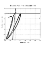
式17による基準による適正領域は、図1にプロットされている。インテリジェントな重力アシスト・コントローラを開発するために、力学的なエネルギーと関連する適正領域とを考察する必要がある。一般的な制御戦略を作成するために、重力が運動を助けるときに系の自然な力学を利用すると共に、重力が運動を妨げるときに重力を補償する制御戦略につながる、本明細書に記載の重力補償コントローラを補完するハイブリッドコントローラを開発することが肝要である。
0 <τ a <2τ n τ n > 0
2τ n <τ a <0 τ n <0 (17)
The appropriate area according to the criterion according to Equation 17 is plotted in FIG. In order to develop an intelligent gravity assist controller, it is necessary to consider the appropriate areas associated with mechanical energy. To create a general control strategy, use the natural mechanics of the system when gravity assists in motion and lead to a control strategy that compensates for gravity when gravity impedes motion It is important to develop a hybrid controller that complements the gravity compensation controller.
本発明の方法およびシステム
上記の記述に基づき、本発明を以下に説明する。
Method and System of the Present Invention Based on the above description, the present invention is described below.
本発明による、筋の負荷を軽減するように、人間アシスト・システムにおいて、人間の関節に加えるアシスト・トルクを求める方法は、人間の各セグメントに関する力およびモーメントの均衡式から、当該セグメントの関節に働く重力によるモーメントを求めるステップを含む。当該方法は、関節に働く重力によるモーメントを補償するように当該関節に与えるアシスト・トルクを求めるステップをさらに含む。 In the human assist system according to the present invention, in the human assist system, the assist torque to be applied to the human joint is calculated from the balance equation of force and moment for each human segment. A step of determining a moment due to working gravity. The method further includes determining an assist torque to be applied to the joint so as to compensate for the moment due to gravity acting on the joint.
本発明による、人間の関節にアシスト・トルクを与えて筋の負荷を軽減するアシスト・システムは、関節にアシスト・トルクを与えるモータと、モータを駆動制御するモータ・ドライバを含む。当該システムは、アシスト・トルクの目標値を定めるコントローラを含み、当該コントローラは、プロセッサとメモリとを含む。当該コントローラは、人間の各セグメントに関する力およびモーメントの均衡式から、当該セグメントの関節に働く重力によるモーメントを求め、つぎに 関節に働く重力によるモーメントを補償するように当該関節に加えるアシスト・トルクを定めるように構成されている。 According to the present invention, an assist system that applies assist torque to a human joint to reduce muscle load includes a motor that applies assist torque to the joint and a motor driver that drives and controls the motor. The system includes a controller that determines a target value of assist torque, and the controller includes a processor and a memory. The controller determines the moment due to gravity acting on the joint of the segment from the balance equation of force and moment for each human segment, and then calculates the assist torque to be applied to the joint so as to compensate for the moment due to gravity acting on the joint. It is configured to determine.
このように、本発明によれば、動作の前進を担当する随意アクチュエータと静的な均衡の維持を担当するアシスト・アクチュエータの間の自然な区分が存在する。この区分は、随意制御と人工的制御の間のインタフェースを減少させる可能性がある。 Thus, according to the present invention, there is a natural division between the discretionary actuator responsible for moving forward and the assist actuator responsible for maintaining static balance. This partition may reduce the interface between voluntary control and artificial control.
本発明の実施形態によれば、関節に働く重力によるモーメントを求めるステップにおいて、足に作用する床反力、足の下の圧力中心および各セグメントの傾斜角度に基づいて関節に働く重力によるモーメントを求める。 According to the embodiment of the present invention, in the step of obtaining the moment due to gravity acting on the joint, the moment due to gravity acting on the joint is determined based on the floor reaction force acting on the foot, the pressure center under the foot, and the inclination angle of each segment. Ask.
このように、複雑な方法を使用せずに、関節に働く重力によるモーメントを簡単に求めることができる。 In this way, the moment due to gravity acting on the joint can be easily obtained without using a complicated method.
本発明の他の実施形態によれば、各セグメントに関する、力およびモーメントの均衡式における重力加速度項以外の加速度項、角加速度項および水平方向の力の項をゼロとして関節に働く重力によるモーメントを求める。 According to another embodiment of the present invention, for each segment, the moment due to gravity acting on the joint is set with zero acceleration term, angular acceleration term and horizontal force term in the balance equation of force and moment as zero. Ask.
このように、質量中心加速度項、角加速度項および水平方向の力の項を測定したり計算したりすることなく、確実に、関節に働く重力によるモーメントを求めることができる。 In this way, the moment due to gravity acting on the joint can be reliably obtained without measuring or calculating the mass center acceleration term, the angular acceleration term, and the horizontal force term.
本発明の他の実施形態によれば、いずれかの関節に加えられたトルクが、重力加速度による実トルクを計算することによって推定される。 According to another embodiment of the invention, the torque applied to any joint is estimated by calculating the actual torque due to gravitational acceleration.
このように、いずれかの関節に加えられたトルクを簡単に推定することができる。 Thus, the torque applied to any joint can be easily estimated.
本発明の他の実施形態によれば、センサによる測定値に基づいて床反力を求める。したがって、確実に床反力を求めることができる。 According to another embodiment of the present invention, the floor reaction force is obtained based on the measured value by the sensor. Therefore, the floor reaction force can be obtained reliably.
本発明の他の実施形態によれば、所定の定数に基づいて床反力を求める。したがって、床反力を必ず、簡単に求めることができる。 According to another embodiment of the present invention, the floor reaction force is obtained based on a predetermined constant. Therefore, the floor reaction force can always be obtained easily.
本発明の他の実施形態によれば、足の下の圧力中心を、センサの測定に基づいて求める。したがって、足の下の圧力中心を確実に求めることができる。 According to another embodiment of the invention, the center of pressure under the foot is determined based on sensor measurements. Therefore, the center of pressure under the foot can be obtained reliably.
本発明の他の実施形態によれば、リアルタイム処理により、アシスト・トルクをリアルタイムに求める。したがって、当該方法およびシステムは、リアルタイムの人間アシスト制御に適している。 According to another embodiment of the present invention, the assist torque is obtained in real time by real time processing. Therefore, the method and system are suitable for real-time human assist control.
本発明の他の実施形態によれば、セグメントが、足部、下腿部および大腿部を含む。したがって、足首関節、膝関節および腰関節の何れに加えられるアシスト・トルクも求めることができる。 According to another embodiment of the invention, the segment includes a foot, a lower leg and a thigh. Therefore, the assist torque applied to any of the ankle joint, the knee joint, and the hip joint can be obtained.
本発明の他の実施形態によれば、センサによる測定値に基づいて各セグメントの傾斜角度を求める。したがって、各セグメントの傾斜角度を確実に求めることができる。 According to another embodiment of the present invention, an inclination angle of each segment is obtained based on a measurement value by a sensor. Therefore, the inclination angle of each segment can be obtained reliably.
本発明の他の実施形態によれば、センサは関節角度を示す関節角度センサである。 According to another embodiment of the present invention, the sensor is a joint angle sensor indicating a joint angle.
本発明の他の実施形態によれば、関節角度センサはポテンショメータである。 According to another embodiment of the invention, the joint angle sensor is a potentiometer.
このように、各セグメントの傾斜角度は、確実に、複雑なセンサを必要とすることなく求めることができる。 In this way, the inclination angle of each segment can be reliably obtained without requiring a complicated sensor.
本発明の他の実施形態によれば、当該方法は、人間が負荷を上昇・下降させる際に使用される。したがって、人間が負荷を上げ下ろしする間に、人間アシスト制御を確実に行うことができる。 According to another embodiment of the invention, the method is used when a human raises or lowers a load. Therefore, human assist control can be reliably performed while the human increases and decreases the load.
本発明の他の実施形態によれば、システムは、外骨格装置型である。したがって、外骨格装置型の人間アシスト・システムの制御を確実に行うことができる。 According to another embodiment of the invention, the system is of an exoskeleton device type. Therefore, the exoskeleton device type human assist system can be reliably controlled.
反復「グランド・アップ」重力補償
ここで、繰り返し表現による重力補償アルゴリズムを示す。この表現は、パラメータの不確かさやモデル化されていない力学に対してよりロバスト性が高い、外骨格装置制御方式を実現するのにより適している。当該アルゴリズムは、鉛直方向の床反力を制約条件として使用し、重力による関節におけるモーメントを反復計算する。多体平面動的システムを考察する。個別の、体のセグメントi(i=1…n)に対して、図2に示すように、
Fi,Gi,およびτiは、それぞれ、セグメントi−1によって、セグメントiに働く水平方向の力、鉛直方向の力および関節モーメントを示す。同様に−Fi+1,−Gi+1,および−τi+1は、それぞれ、セグメントi+1によって、セグメントiに働く水平方向の力、鉛直方向の力および関節モーメントを示す。各セグメントにおける力およびモーメントの均衡から以下のニュートン・オイラー方程式が導出される。 F i , G i , and τ i indicate the horizontal force, the vertical force, and the joint moment acting on the segment i by the segment i−1, respectively. Similarly, −F i + 1 , −G i + 1 , and −τ i + 1 indicate a horizontal force, a vertical force, and a joint moment acting on the segment i by the segment i + 1, respectively. The following Newton Euler equations are derived from the balance of forces and moments in each segment.
リンク1は足(foot)であり、F1,Giは、足の下の圧力中心に作用する床反力である。足の下の圧力中心における反力モーメントは、ゼロと考える。すなわち、τ1=0である。長さ liは、足の下の圧力中心から始まり足首関節で終わる。長さkiは足の下の圧力中心から始まり足の質量中心で終わる。各セグメントの質量中心の座標は、運動学の式を使用して計算される。
The
上記のニュートン・オイラー方程式を使用して、「グランド・アップ」逆動力学手順は、運動学と床反力を利用して、連続する関節における実関節力と実関節モーメントとを繰り返し推定する。式20は、関節iにおける実関節トルク
適切な制約条件を備えると、「グランド・アップ」逆動力学方程式は、「グランド・アップ」重力補償アルゴリズムを展開するのに使用することもできる。式18乃至20から、すべての加速度および水平方向関節反力をゼロとすることにより、関節モーメントにおける重力および鉛直方向静負荷の寄与を観察することができる。 With appropriate constraints, the “ground up” inverse dynamic equation can also be used to develop a “ground up” gravity compensation algorithm. From Equations 18 to 20, the contribution of gravity and vertical static load to the joint moment can be observed by setting all accelerations and horizontal joint reaction forces to zero.
すなわち、
上記の式は、鉛直方向静的負荷の効果を実モーメントに関係づけているので、床反力に対する制約条件は、
ここで、Geは、外的負荷による鉛直方向の実静的力であり、
関節i(i=1…n)がすべて作動しているとする。各関節において目標のアシスト制御を生成するのに使用される重力補償制御則は、
τa(1)= 0 (27)
τa(i+1)=τg(i+1) (28)
である。すべての関節における目標のアシスト・トルクは、単に
τa(desire)=[τa(1),τa(2),…τa(n)] (29)
によって生成されるベクトルである。関節が作動していなければ、当該関節におけるアシスト・トルクは、単にゼロである。
Assume that all joints i (i = 1... N) are operating. The gravity compensation control law used to generate the target assist control at each joint is
τ a (1) = 0 (27)
τ a (i + 1) = τ g (i + 1) (28)
It is. The target assist torque for all joints is simply
τ a (desire) = [τ a (1), τ a (2),… τ a (n)] (29)
Is a vector generated by If the joint is not operating, the assist torque at that joint is simply zero.
全システム
重力補償コントローラ、外骨格装置アクチュエータ・システムおよび人間と外骨格装置を含む全システムのブロック図を図3に示す。外骨格装置アクチュエータ制御システムは、上記の重力補償コントローラを使用して計算された目標アシスト・トルクを取り込み、その出力に当該目標アシスト・トルクを生成するように試みる。人間の関節を駆動するのに使用される実際のアシスト・トルクは、当該外骨格装置アクチュエータ・システムの出力である。重力補償コントローラおよび外骨格装置アクチュエータ・システムが、人間アシスト・システムを構成する。
A block diagram of the entire system including the entire system gravity compensation controller, exoskeleton device actuator system and human and exoskeleton device is shown in FIG. The exoskeleton device actuator control system takes in the target assist torque calculated using the gravity compensation controller described above and attempts to generate the target assist torque in its output. The actual assist torque used to drive the human joint is the output of the exoskeleton device actuator system. The gravity compensation controller and exoskeleton device actuator system constitute the human assist system.
人間アシスト・システム
人間アシスト・システムのブロック図を図5に示す。上述のように、人間アシスト・システムは、重力補償コントローラ100および外骨格装置アクチュエータ・システム200を含む。重力補償コントローラ100は、CPU(中央処理装置)101、メモリ102、D/Aコンバータ103、A/Dコンバータ104およびデジタル入出力ユニット105を備える。外骨格装置アクチュエータ・システム200は、関節の各々に目標のアシスト・トルクを供給するアクチュエータ・ユニットを備える。関節には、両方の足首の関節、両方の膝の関節および両方の腰の関節が含まれる。これらの関節用に複数のアクチュエータ・ユニットを備える。各アクチュエータ・ユニットは、モータ・ドライバ201、DCサーボモータ202、ギア203およびポテンショメータ204を含む。
Human Assist System A block diagram of the human assist system is shown in FIG. As described above, the human assist system includes the
始動・停止スイッチ2がオン状態に設定される(すなわち、始動スイッチがオンされる)と、重力補償コントローラ100は、動作を開始する。始動・停止スイッチ2がオフ状態に設定される(すなわち、停止スイッチがオンされる)と、重力補償コントローラ100は、動作を停止する。始動・停止スイッチ2がオン状態に設定される間、重力補償コントローラは、式22乃至29に基づいて所定の間隔で各関節用の目標アシスト・トルクを反復的に計算する。式26において、Gg(1)は、床反力センサ1を使用した測定により求めることができる。床反力センサ1は、足の底面または床に設置されたロード・セル・タイプのものでもよい。代替的に、Gg(1)は、メモリ102に記憶されたデータを使用して求めることができる。各足の下の足の下の圧力中心は計算するか靴の中の圧力センサを使用して測定する。各セグメントの質量、各セグメントの質量中心の位置および各セグメントの長さは、以下の文献に報告されている回帰式を使用して求めてもよい。
When the start /
(3)Winter D.A(1990), Biomechanic and Motor Control of Human Movement, 2nd Edition, Jhon Wiley & Sons, Inc. (3) Winter DA (1990) , Biomechanic and Motor Control of Human Movement, 2 nd Edition, Jhon Wiley & Sons, Inc.
人間によって持ち上げられまたは運搬される外的負荷の質量を予め測定することによって知ることもできる。当該質量は、右側のセメントおよび左側のセグメントによって等しく分担されると仮定してもよい。式23において、鉛直方向に対する関節角度(関節傾き角度)θiは、各関節におけるポテンショメータ204の出力に基づいて求めることができる。ポテンショメータ204の出力は、関節における曲げ角度(関節曲げ角度)を表す。鉛直方向に対する関節角度θiは、各関節における曲げ角度から計算することができる。
It is also possible to know by measuring in advance the mass of an external load that is lifted or carried by a human. It may be assumed that the mass is equally shared by the right cement and the left segment. In Expression 23, the joint angle (joint inclination angle) θ i with respect to the vertical direction can be obtained based on the output of the
重力補償コントローラ100は、各関節に対するアシスト・トルクの目標値を、D/Aコンバータ103を介して各アクチュエータのモータ・ドライバ201に出力する。各アクチュエータ・ユニットにおいて、モータ・ドライバ201は、各関節に目標のアシスト・トルクを供給するようにDCサーボモータ202を駆動する。
The
動作プロセス
図6は、人間アシスト・システムの動作プロセスの流れ図を示す。
Operation Process FIG. 6 shows a flow diagram of the operation process of the human assist system.
ステップS605において、始動スイッチ2がオンされたときに時間がゼロに設定される。ステップS610において、床反力の静的鉛直方向成分が、測定または推定により求められる。
In step S605, the time is set to zero when the
ステップS615において、鉛直方向に対する関節角度(セグメントiの向き)がセンサによって求められる。当該センサは、各関節iにおけるポテンショメータでもよい。ステップS620において、重力に打ち克つ、関節iにおける目標のアシスト・トルクが、式22乃至29に基づいて計算される。 In step S615, the joint angle (direction of segment i) with respect to the vertical direction is obtained by the sensor. The sensor may be a potentiometer at each joint i. In step S620, the target assist torque at joint i that overcomes gravity is calculated based on equations 22-29.
ステップS625において、すべてのセグメントに対して計算が実行されたか否かが判断される。いずれかのセグメントに対して計算が実行されていなければ、ステップS630において、iに対するカウンタが1増分され、プロセスはステップS615に戻る。すべてのセグメントに対して計算が実行されていれば、プロセスはS635に進む。 In step S625, it is determined whether calculations have been performed for all segments. If no computation has been performed for any segment, in step S630, the counter for i is incremented by 1, and the process returns to step S615. If calculations have been performed for all segments, the process proceeds to S635.
ステップS635において、目標のアシスト・トルクを生成するように、D/Aコンバータを介して各アクチュエータ・ユニットへ目標のアシスト・トルクが出力される。ステップS640において、所定の時間間隔を空ける。 In step S635, the target assist torque is output to each actuator unit via the D / A converter so as to generate the target assist torque. In step S640, a predetermined time interval is provided.
ステップS645において、停止スイッチ2がオンされているか否かが判断される。判定の結果が肯定的であれば、プロセスは終了する。判定の結果が否定的であれば、プロセスは、S610に戻る。
In step S645, it is determined whether or not the
シミュレーション
人手による物品処理作業を表す質量の上昇・下降運動に対して、重力補償プロトコルをシミュレーションした。図4に示すように、足、脚下部、脚上部、胴体、腕上部および腕下部をモデル化している6リンクの平面システムを、解析を行うために使用する。持ち上げることの、種々の力学的または運動学的パラメータに対する、動的な要因や外部質量の効果は、バイオメカニクス研究者によって広く研究されている。以下の文献を参照されたい。
Simulation A gravity compensation protocol was simulated for mass ascending / descending motions that represent manual processing of articles. As shown in FIG. 4, a 6-link planar system modeling the foot, lower leg, upper leg, torso, upper arm and lower arm is used to perform the analysis. The effects of dynamic factors and external mass on the various mechanical or kinematic parameters of lifting have been extensively studied by biomechanics researchers. See the following references:
(4)D. Gagnon and M. Gagnon. The influence of dynamic factors on triaxial net muscular moments at the l5/s1 joint during asymmetrical lifting and lowering. Journal of Biomechanics, 25:891−901, 1992.
(5)S. H. Hsiang and R. W. McGorry. Three different lifting strategies for controlling the motion patterns of the external load. Ergonomics, 40:928−939, 1997。
(4) D. Gagnon and M. Gagnon. The influence of dynamic factors on triaxial net muscular moments at the l5 / s1 joint during asymmetrical lifting and lowering. Journal of Biomechanics, 25: 891-901, 1992.
(5) SH Hsiang and RW McGorry. Three different lifting strategies for controlling the motion patterns of the external load. Ergonomics, 40: 928-939, 1997.
このような研究は、人間工学的な介入を識別することによりリスク要因を減少させるために行われてきた。 Such research has been done to reduce risk factors by identifying ergonomic interventions.
図7は、10kgの質量の上昇・下降運動に対する5関節の運動軌跡を示す。図8は、膝におけるアシスト・トルク、筋トルクおよび実関節トルクの大きさの、シミュレーションされた比較を示す。膝における筋トルクが膝における実関節トルクを超える領域においては、重力補償制御は、作業を行うために筋によって要求される機械的なパワーを増加させる。本解析によっては、代謝のパワーが各瞬間において増加しているか減少しているかを予測することはできない。代謝コストに関する重力補償の効果を完全に理解するには、より複雑なツールが必要である。さらに、重力補償は、実際には、機械的な仕事を増加させる犠牲により、安定性を増加させている可能性もある。 FIG. 7 shows the motion trajectories of the five joints with respect to the ascending / descending motion of the mass of 10 kg. FIG. 8 shows a simulated comparison of the magnitude of assist torque, muscle torque and actual joint torque at the knee. In areas where the muscle torque at the knee exceeds the actual joint torque at the knee, gravity compensation control increases the mechanical power required by the muscle to perform the task. This analysis cannot predict whether metabolic power will increase or decrease at each moment. A more complex tool is needed to fully understand the effects of gravity compensation on metabolic costs. Furthermore, gravity compensation may actually increase stability at the expense of increasing mechanical work.
図9は、腰におけるアシスト・トルク、筋トルクおよび実関節トルクの大きさの、シミュレーションされた比較を示す。腰における筋トルクが腰における実関節トルクを超える領域においては、重力補償制御は、作業を行うために筋によって要求される機械的なパワーを増加させる。 FIG. 9 shows a simulated comparison of the magnitude of assist torque, muscle torque and actual joint torque at the waist. In the region where the muscle torque at the waist exceeds the actual joint torque at the waist, gravity compensation control increases the mechanical power required by the muscle to perform the task.
図10は、膝におけるアシスト・トルク、筋トルクおよび実関節トルクの、シミュレーションされた比較を示す。アシスト・トルクと実関節トルクの符号が反対の領域においては、重力補償は、運動の効率を減少させる。 FIG. 10 shows a simulated comparison of assist torque, muscle torque and actual joint torque at the knee. In areas where the signs of assist torque and actual joint torque are opposite, gravity compensation reduces the efficiency of the movement.
図11は、腰におけるアシスト・トルク、筋トルクおよび実関節トルクの、シミュレーションされた比較を示す。アシスト・トルクと実関節トルクの符号が反対の領域においては、重力補償は、運動の効率を減少させる。 FIG. 11 shows a simulated comparison of assist torque, muscle torque and actual joint torque at the waist. In areas where the signs of assist torque and actual joint torque are opposite, gravity compensation reduces the efficiency of the movement.
図12は、膝における関節パワーを推定するための量を示す。上段の関節トルクおよび中段の関節角速度が含まれる。関節パワーは、下段のグラフにプロットされている。調整後の関節パワーは、正および負の仕事の代謝コスト・インデックスを考慮している。文献から利用可能なデータに基づいて、本シミュレーションにおいては、n−=1.5 および n+=1.0を使用した。 FIG. 12 shows the quantities for estimating the joint power at the knee. Upper joint torque and middle joint angular velocity are included. The joint power is plotted in the lower graph. Adjusted joint power takes into account the metabolic cost index of positive and negative work. Based on data available from the literature, n − = 1.5 and n + = 1.0 were used in this simulation.
図13は、腰における関節パワーを推定するための量を示す。上段の関節トルクおよび中段の関節角速度が含まれる。関節パワーは、下段のグラフにプロットされている。調整後の関節パワーは、正および負の仕事の代謝コスト・インデックスを考慮している。文献から利用可能なデータに基づいて、本シミュレーションにおいては、n−=1.5 および n+=1.0を使用した。 FIG. 13 shows quantities for estimating joint power at the waist. Upper joint torque and middle joint angular velocity are included. The joint power is plotted in the lower graph. Adjusted joint power takes into account the metabolic cost index of positive and negative work. Based on data available from the literature, n − = 1.5 and n + = 1.0 were used in this simulation.
図14は、膝関節において、アシスト・トルク対実関節トルクの適正領域を示す。重力アシストの実施可能領域は、プロット記号「X」によって示される。プロット記号「O」の領域は、適正ではない随意筋トルクを発生させる。 FIG. 14 shows an appropriate region of assist torque versus actual joint torque in the knee joint. The area where gravity assist can be performed is indicated by the plot symbol “X”. The area of the plot symbol “O” generates an involuntary voluntary muscle torque.
図15は、腰関節において、アシスト・トルク対実関節トルクの適正領域を示す。重力アシストの実施可能領域は、プロット記号「X」によって示される。プロット記号「O」の領域は、適正ではない随意筋トルクを発生させる。 FIG. 15 shows an appropriate region of assist torque versus actual joint torque in the waist joint. The area where gravity assist can be performed is indicated by the plot symbol “X”. The area of the plot symbol “O” generates an involuntary voluntary muscle torque.
図8乃至11は、膝および腰における筋トルクが、実関節トルクと比較して、かなり減少することを示す。このことは、反復「グランド・アップ」重力補償が、この作業を行うために筋によって要求される仕事を大幅に減少させたことを意味する。 Figures 8 to 11 show that the muscle torque at the knee and waist is significantly reduced compared to the actual joint torque. This means that iterative “ground up” gravity compensation has significantly reduced the work required by the muscle to do this task.
100 重力補償コントローラ
101 CPU
102 メモリ
200 外骨格装置アクチュエータ
201 モータ・ドライバ
202 モータ
100
102
Claims (17)
足の下の圧力中心に作用する床反力を求めるステップと、
足の下の圧力中心における反力モーメントはゼロとして、下腿部における力およびモーメントの均衡式における重力加速度項以外の加速度項、角加速度項および水平方向の力の項をゼロとして膝関節に働く重力によるモーメントを求めるステップと、
大腿部における力およびモーメントの均衡式における重力加速度項以外の加速度項、角加速度項および水平方向の力の項をゼロとして腰関節に働く重力によるモーメントを求めるステップと、
該膝関節および該腰関節に働く重力によるモーメントを補償するように該膝関節および該腰関節に与えるアシスト・トルクを求めるステップと、を含む方法。 In an assist system that reduces the muscle load by applying assist torque to a human joint, a method for obtaining assist torque to be applied to the joint,
Determining the floor reaction force acting on the pressure center under the foot;
The reaction force moment at the pressure center under the foot is zero, and the acceleration term other than the gravitational acceleration term, the angular acceleration term, and the horizontal force term in the balance equation of force and moment in the lower leg are zero and work on the knee joint Obtaining a moment due to gravity;
Obtaining a moment due to gravity acting on the hip joint with zero acceleration term other than the gravitational acceleration term in the balance equation of force and moment in the thigh, angular acceleration term and horizontal force term;
Determining an assist torque to be applied to the knee joint and the hip joint so as to compensate for a moment due to gravity acting on the knee joint and the hip joint.
Applications Claiming Priority (3)
| Application Number | Priority Date | Filing Date | Title |
|---|---|---|---|
| US41302402P | 2002-09-23 | 2002-09-23 | |
| US42196402P | 2002-10-28 | 2002-10-28 | |
| US48470803P | 2003-07-03 | 2003-07-03 |
Publications (2)
| Publication Number | Publication Date |
|---|---|
| JP2004114292A JP2004114292A (en) | 2004-04-15 |
| JP4493961B2 true JP4493961B2 (en) | 2010-06-30 |
Family
ID=32234189
Family Applications (1)
| Application Number | Title | Priority Date | Filing Date |
|---|---|---|---|
| JP2003330149A Expired - Fee Related JP4493961B2 (en) | 2002-09-23 | 2003-09-22 | Gravity compensation method in human assist system and human assist system with gravity compensation |
Country Status (5)
| Country | Link |
|---|---|
| US (1) | US7217247B2 (en) |
| EP (1) | EP1422128B1 (en) |
| JP (1) | JP4493961B2 (en) |
| AT (1) | ATE488424T1 (en) |
| DE (1) | DE60334966D1 (en) |
Families Citing this family (55)
| Publication number | Priority date | Publication date | Assignee | Title |
|---|---|---|---|---|
| US7135003B2 (en) * | 2001-06-29 | 2006-11-14 | Honda Giken Kogyo Kabushiki Kaisha | Feedback estimation of joint forces and joint moments |
| US7623944B2 (en) * | 2001-06-29 | 2009-11-24 | Honda Motor Co., Ltd. | System and method of estimating joint loads in a three-dimensional system |
| US7217247B2 (en) | 2002-09-23 | 2007-05-15 | Honda Giken Kogyo Kabushiki Kaisha | Gravity compensation method in a human assist system and a human assist system with gravity compensation control |
| US7650204B2 (en) * | 2001-06-29 | 2010-01-19 | Honda Motor Co., Ltd. | Active control of an ankle-foot orthosis |
| US7469166B2 (en) * | 2001-06-29 | 2008-12-23 | Honda Motor Co., Ltd. | System and method of predicting novel motion in a serial chain system |
| US7774177B2 (en) * | 2001-06-29 | 2010-08-10 | Honda Motor Co., Ltd. | Exoskeleton controller for a human-exoskeleton system |
| US7684896B2 (en) * | 2001-06-29 | 2010-03-23 | Honda Motor Co., Ltd. | System and method of estimating joint loads using an approach of closed form dynamics |
| US7390309B2 (en) * | 2002-09-23 | 2008-06-24 | Honda Motor Co., Ltd. | Human assist system using gravity compensation control system and method using multiple feasibility parameters |
| JP4133216B2 (en) * | 2001-10-29 | 2008-08-13 | 本田技研工業株式会社 | Human assist device simulation system, method, and computer program |
| US7402142B2 (en) * | 2002-09-23 | 2008-07-22 | Honda Giken Kogyo Kabushiki Kaisha | Method and processor for obtaining moments and torques in a biped walking system |
| US6966882B2 (en) * | 2002-11-25 | 2005-11-22 | Tibion Corporation | Active muscle assistance device and method |
| JP4178186B2 (en) * | 2003-08-21 | 2008-11-12 | 国立大学法人 筑波大学 | Wearable motion assist device, control method for wearable motion assist device, and control program |
| US7628766B1 (en) * | 2003-10-29 | 2009-12-08 | The Regents Of The University Of California | Lower extremity enhancer |
| JP4971977B2 (en) * | 2004-03-31 | 2012-07-11 | 本田技研工業株式会社 | A method for controlling a legged robot based on the rate of change of angular momentum |
| WO2006092872A1 (en) * | 2005-02-28 | 2006-09-08 | National University Corporation NARA Institute of Science and Technology | Driving force computing device, driving force computing method, muscle force assisting device, program, and computer-readable recording medium |
| US7835822B2 (en) * | 2005-03-30 | 2010-11-16 | Honda Motor Co., Ltd. | Systems and methods for controlling a legged robot using a two-phase disturbance response strategy |
| ATE426379T1 (en) | 2005-04-12 | 2009-04-15 | Honda Motor Co Ltd | ACTIVE CONTROL OF AN ANKLE BORTHESIS |
| EP1874239B1 (en) * | 2005-04-13 | 2014-06-11 | The Regents of The University of California | Semi-powered lower extremity exoskeleton |
| US8082062B2 (en) * | 2005-06-10 | 2011-12-20 | Honda Motor Co., Ltd. | Regenerative actuation in motion control |
| US7573477B2 (en) * | 2005-06-17 | 2009-08-11 | Honda Motor Co., Ltd. | System and method for activation-driven muscle deformations for existing character motion |
| JP4712620B2 (en) | 2006-06-12 | 2011-06-29 | 本田技研工業株式会社 | Control device for walking aids |
| JP4666644B2 (en) * | 2006-07-12 | 2011-04-06 | 本田技研工業株式会社 | Control device for walking aids |
| US8353854B2 (en) | 2007-02-14 | 2013-01-15 | Tibion Corporation | Method and devices for moving a body joint |
| EP2122185A1 (en) * | 2007-02-28 | 2009-11-25 | Raytheon Sarcos, LLC | Antagonistic fluid control system for active and passive actuator operation |
| US8051764B2 (en) * | 2007-02-28 | 2011-11-08 | Raytheon Company | Fluid control system having selective recruitable actuators |
| PL2326288T3 (en) | 2008-05-20 | 2016-09-30 | Device and method for decreasing energy consumption of a person by use of a lower extremity exoskeleton | |
| US20090306548A1 (en) | 2008-06-05 | 2009-12-10 | Bhugra Kern S | Therapeutic method and device for rehabilitation |
| US9351855B2 (en) | 2008-06-16 | 2016-05-31 | Ekso Bionics, Inc. | Powered lower extremity orthotic and method of operation |
| CA2731612C (en) * | 2008-07-23 | 2018-03-20 | Berkeley Bionics | An exoskeleton and method for controlling a swing leg of the exoskeleton |
| WO2010088262A2 (en) * | 2009-01-27 | 2010-08-05 | University Of Washington | Prosthetic limb monitoring system |
| US20100312083A1 (en) * | 2009-04-20 | 2010-12-09 | Phil Southerland | System for Monitoring Glucose and Measuring Wattage |
| KR20120060578A (en) * | 2010-12-02 | 2012-06-12 | 삼성전자주식회사 | Walking robot and method for controlling balancing the same |
| KR20120071599A (en) * | 2010-12-23 | 2012-07-03 | 삼성전자주식회사 | Walking robot and control method thereof |
| ITFI20110232A1 (en) * | 2011-10-21 | 2013-04-22 | Zionamento Sant Anna | METHOD FOR CALCULATING THE MASS CENTER FOR A UMANOID PLATFORM |
| US9675514B2 (en) | 2013-03-15 | 2017-06-13 | Bionik Laboratories, Inc. | Transmission assembly for use in an exoskeleton apparatus |
| US9421143B2 (en) | 2013-03-15 | 2016-08-23 | Bionik Laboratories, Inc. | Strap assembly for use in an exoskeleton apparatus |
| US9855181B2 (en) | 2013-03-15 | 2018-01-02 | Bionik Laboratories, Inc. | Transmission assembly for use in an exoskeleton apparatus |
| US9808390B2 (en) | 2013-03-15 | 2017-11-07 | Bionik Laboratories Inc. | Foot plate assembly for use in an exoskeleton apparatus |
| WO2014151584A1 (en) | 2013-03-15 | 2014-09-25 | Alterg, Inc. | Orthotic device drive system and method |
| US20150025423A1 (en) | 2013-07-19 | 2015-01-22 | Bionik Laboratories, Inc. | Control system for exoskeleton apparatus |
| KR102115950B1 (en) * | 2013-11-07 | 2020-06-05 | 삼성전자주식회사 | A walk-assistive robot and a method for controlling the walk-assistive robot |
| KR102131277B1 (en) | 2013-12-30 | 2020-07-07 | 삼성전자주식회사 | A walk-assistive apparatus and a method for controlling the walk-assistive apparatus |
| US9757254B2 (en) * | 2014-08-15 | 2017-09-12 | Honda Motor Co., Ltd. | Integral admittance shaping for an exoskeleton control design framework |
| US11938050B2 (en) * | 2015-12-14 | 2024-03-26 | Board Of Regents, The University Of Texas System | Torque control methods and devices for powered orthosis |
| EP3450115B1 (en) * | 2016-06-08 | 2021-03-31 | Nintendo Co., Ltd. | Passive walking device and passive walking module |
| US10195098B2 (en) | 2016-09-22 | 2019-02-05 | Gordon Roeder | Decompression chair for lower back |
| US10004614B1 (en) | 2016-11-02 | 2018-06-26 | Joe Johnson | Disarticulated compression socket |
| US11844667B2 (en) | 2016-11-02 | 2023-12-19 | Joe Johnson | Disarticulated compression socket |
| US10710237B2 (en) * | 2017-03-22 | 2020-07-14 | Jtekt Corporation | Assist device |
| CN109634100B (en) * | 2018-12-30 | 2021-11-02 | 深圳市优必选科技有限公司 | Humanoid robot walking acceleration compensation method and device and humanoid robot |
| US11123608B2 (en) * | 2019-03-05 | 2021-09-21 | Hiwin Technologies Corp. | Upper limb training system and control method thereof |
| KR102234788B1 (en) | 2020-07-01 | 2021-04-01 | 삼성전자주식회사 | A walk-assistive apparatus and a method for controlling the walk-assistive apparatus |
| CN111538234B (en) * | 2020-07-08 | 2020-10-09 | 深圳市优必选科技股份有限公司 | Task hierarchical control method and device, robot and readable storage medium |
| CN113043279B (en) * | 2021-04-15 | 2022-08-02 | 诺创智能医疗科技(杭州)有限公司 | Control method, controller, system, electronic device and medium for surgical robot |
| CN113696177B (en) * | 2021-07-29 | 2022-12-27 | 杭州程天科技发展有限公司 | Control and evaluation method and system applied to exoskeleton robot |
Citations (2)
| Publication number | Priority date | Publication date | Assignee | Title |
|---|---|---|---|---|
| JP2002096283A (en) * | 2000-09-19 | 2002-04-02 | Tokai Univ | Revolute joint control device of mobile robot |
| JP2003080478A (en) * | 2001-09-07 | 2003-03-18 | Gifu Univ | Attitude control device and control method of machine having leg |
Family Cites Families (52)
| Publication number | Priority date | Publication date | Assignee | Title |
|---|---|---|---|---|
| US4244120A (en) | 1979-06-11 | 1981-01-13 | The United States Of America As Represented By The Secretary Of The Navy | Acceleration cueing simulation device |
| US5136227A (en) | 1985-09-10 | 1992-08-04 | Agency Of Industrial Science & Technology, Ministry Of International Trade & Industry | Active gravity compensation device for force control system |
| US4786847A (en) | 1986-11-20 | 1988-11-22 | Unimation Inc. | Digital control for multiaxis robots |
| JPS63150176A (en) | 1986-12-15 | 1988-06-22 | 工業技術院長 | Walking control method of dynamic walking robot |
| US5044360A (en) | 1989-12-26 | 1991-09-03 | United States Manufacturing Company | Orthosis with variable motion controls |
| JP3104249B2 (en) | 1990-10-17 | 2000-10-30 | オムロン株式会社 | Feedback control device |
| US5625577A (en) | 1990-12-25 | 1997-04-29 | Shukyohojin, Kongo Zen Sohonzan Shorinji | Computer-implemented motion analysis method using dynamics |
| US5432417A (en) | 1992-04-30 | 1995-07-11 | Honda Giken Kogyo Kabushiki Kaisha | Locomotion control system for legged mobile robot |
| JP3269852B2 (en) | 1992-05-29 | 2002-04-02 | 本田技研工業株式会社 | Posture stabilization control device for legged mobile robot |
| US5362288A (en) | 1993-03-26 | 1994-11-08 | Eli Razon | Device for assisting running, walking or jumping |
| US5323549A (en) | 1993-08-16 | 1994-06-28 | Sports Licensing, Inc. | Shoe equipped with internal orthotic cradle device |
| US5570286A (en) | 1993-12-23 | 1996-10-29 | Lord Corporation | Regenerative system including an energy transformer which requires no external power source to drive same |
| JP2761574B2 (en) * | 1994-07-06 | 1998-06-04 | 工業技術院長 | Method of controlling force assist device and device thereof |
| US5835693A (en) | 1994-07-22 | 1998-11-10 | Lynch; James D. | Interactive system for simulation and display of multi-body systems in three dimensions |
| US5659480A (en) | 1995-06-27 | 1997-08-19 | Industrial Service And Machine, Incorporated | Method for coordinating motion control of a multiple axis machine |
| KR100439466B1 (en) * | 1995-09-11 | 2004-09-18 | 가부시키가이샤 야스가와덴끼 | Robot controller |
| US5808433A (en) | 1995-09-29 | 1998-09-15 | Honda Giken Kogyo Kabushiki Kaisha | Method of generating gait of legged walking robot and system for controlling its locomotion |
| US5706589A (en) | 1996-06-13 | 1998-01-13 | Marc; Michel | Energy managing shoe sole construction |
| US5982389A (en) | 1996-06-17 | 1999-11-09 | Microsoft Corporation | Generating optimized motion transitions for computer animated objects |
| RU2107328C1 (en) | 1996-08-14 | 1998-03-20 | Нурахмед Нурисламович Латыпов | Method for tracing and displaying of position and orientation of user in three-dimensional space and device which implements said method |
| US6364888B1 (en) | 1996-09-09 | 2002-04-02 | Intuitive Surgical, Inc. | Alignment of master and slave in a minimally invasive surgical apparatus |
| DE69734835T2 (en) | 1996-12-19 | 2006-07-20 | Honda Giken Kogyo K.K. | POSITIVE CONTROLLER ON A ROBOT MOVING ON LEGS |
| JP3375843B2 (en) | 1997-01-29 | 2003-02-10 | 本田技研工業株式会社 | Robot autonomous traveling method and autonomous traveling robot control device |
| US5942869A (en) | 1997-02-13 | 1999-08-24 | Honda Giken Kogyo Kabushiki Kaisha | Mobile robot control device |
| DE29719250U1 (en) | 1997-10-30 | 1998-05-07 | Hauptverband Der Gewerblichen | Body stress measurement and analysis system |
| US6161080A (en) | 1997-11-17 | 2000-12-12 | The Trustees Of Columbia University In The City Of New York | Three dimensional multibody modeling of anatomical joints |
| US6045524A (en) | 1997-12-19 | 2000-04-04 | Kabushiki Kaisha Tatematsu Seisakusho | Joint of orthotic apparatus |
| US6289265B1 (en) | 1998-04-20 | 2001-09-11 | Honda Giken Kogyo Kabushiki Kaisha | Controller for legged mobile robot |
| DE69941304D1 (en) | 1998-09-14 | 2009-10-01 | Univ R | CONDITIONAL STATEMENT OF A JOINT AND DAMAGE |
| JP3497402B2 (en) | 1999-02-25 | 2004-02-16 | 日本電信電話株式会社 | Exercise state generation device and recording medium recording exercise state generation program |
| SE514921C2 (en) | 1999-06-22 | 2001-05-21 | Atlas Copco Tools Ab | Method for determining optimal values for screw tightening parameters by operating simulation |
| JP3555107B2 (en) | 1999-11-24 | 2004-08-18 | ソニー株式会社 | Legged mobile robot and operation control method for legged mobile robot |
| JP3615702B2 (en) * | 1999-11-25 | 2005-02-02 | ソニー株式会社 | Motion control device and motion control method for legged mobile robot, and legged mobile robot |
| US6750866B1 (en) | 2000-04-21 | 2004-06-15 | Realistic Dynamics, Inc. | Method and system for dynamically filtering the motion of articulated bodies |
| US6633783B1 (en) | 2000-06-06 | 2003-10-14 | Honda Giken Kogyo Kabushiki Kaisha | Fuzzy logic based control |
| US6445983B1 (en) | 2000-07-07 | 2002-09-03 | Case Corporation | Sensor-fusion navigator for automated guidance of off-road vehicles |
| JP4252721B2 (en) | 2000-11-17 | 2009-04-08 | 本田技研工業株式会社 | Biped robot |
| JP3760186B2 (en) | 2001-06-07 | 2006-03-29 | 独立行政法人科学技術振興機構 | Biped walking type moving device, walking control device thereof, and walking control method |
| DE10130485C2 (en) | 2001-06-25 | 2003-06-26 | Robert Riener | Programmable joint simulator |
| JP4611580B2 (en) | 2001-06-27 | 2011-01-12 | 本田技研工業株式会社 | Torque application system |
| US7217247B2 (en) | 2002-09-23 | 2007-05-15 | Honda Giken Kogyo Kabushiki Kaisha | Gravity compensation method in a human assist system and a human assist system with gravity compensation control |
| US7623944B2 (en) | 2001-06-29 | 2009-11-24 | Honda Motor Co., Ltd. | System and method of estimating joint loads in a three-dimensional system |
| US7390309B2 (en) | 2002-09-23 | 2008-06-24 | Honda Motor Co., Ltd. | Human assist system using gravity compensation control system and method using multiple feasibility parameters |
| US7135003B2 (en) | 2001-06-29 | 2006-11-14 | Honda Giken Kogyo Kabushiki Kaisha | Feedback estimation of joint forces and joint moments |
| JP3944566B2 (en) | 2001-07-30 | 2007-07-11 | 国立大学法人 東京大学 | A method of dynamically determining joint acceleration in a link mechanism. |
| JP3833567B2 (en) | 2002-05-01 | 2006-10-11 | 本田技研工業株式会社 | Mobile robot attitude control device |
| EP1550401A4 (en) | 2002-05-29 | 2008-03-19 | Japan Science & Tech Agency | Body mechanics calculating method, body mechanics model, its model data, and body model producing method |
| US6971267B2 (en) | 2002-09-23 | 2005-12-06 | Honda Giken Kogyo Kabushiki Kaisha | Method and processor for obtaining moments and torques in a biped walking system |
| JP2004174704A (en) | 2002-11-14 | 2004-06-24 | Sony Corp | Actuator device and multishaft type robot |
| US6966882B2 (en) | 2002-11-25 | 2005-11-22 | Tibion Corporation | Active muscle assistance device and method |
| US8579771B2 (en) | 2004-08-11 | 2013-11-12 | Omnitek Partners Llc | Walk-assist devices and methods |
| US20060139355A1 (en) | 2004-12-27 | 2006-06-29 | Seyoon Tak | Physically based motion retargeting filter |
-
2003
- 2003-09-05 US US10/655,460 patent/US7217247B2/en active Active
- 2003-09-18 AT AT03021211T patent/ATE488424T1/en not_active IP Right Cessation
- 2003-09-18 EP EP03021211A patent/EP1422128B1/en not_active Expired - Lifetime
- 2003-09-18 DE DE60334966T patent/DE60334966D1/en not_active Expired - Lifetime
- 2003-09-22 JP JP2003330149A patent/JP4493961B2/en not_active Expired - Fee Related
Patent Citations (2)
| Publication number | Priority date | Publication date | Assignee | Title |
|---|---|---|---|---|
| JP2002096283A (en) * | 2000-09-19 | 2002-04-02 | Tokai Univ | Revolute joint control device of mobile robot |
| JP2003080478A (en) * | 2001-09-07 | 2003-03-18 | Gifu Univ | Attitude control device and control method of machine having leg |
Also Published As
| Publication number | Publication date |
|---|---|
| EP1422128A3 (en) | 2008-12-17 |
| DE60334966D1 (en) | 2010-12-30 |
| EP1422128B1 (en) | 2010-11-17 |
| US7217247B2 (en) | 2007-05-15 |
| US20050102111A1 (en) | 2005-05-12 |
| EP1422128A2 (en) | 2004-05-26 |
| ATE488424T1 (en) | 2010-12-15 |
| JP2004114292A (en) | 2004-04-15 |
Similar Documents
| Publication | Publication Date | Title |
|---|---|---|
| JP4493961B2 (en) | Gravity compensation method in human assist system and human assist system with gravity compensation | |
| JP4708421B2 (en) | Gravity compensation control system and method using feasibility multiple parameters | |
| Reinkensmeyer et al. | Slacking by the human motor system: computational models and implications for robotic orthoses | |
| JP4981786B2 (en) | Exoskeleton controller for human-exoskeleton system | |
| EP1306792B1 (en) | Simulation system and method for human augmentation devices | |
| US9980842B2 (en) | Motion assist device and motion assist method, computer program, and program recording medium | |
| Ugurlu et al. | Active compliance control reduces upper body effort in exoskeleton-supported walking | |
| EP1868546B1 (en) | Active control of an ankle-foot orthosis | |
| CN105050563A (en) | Powered orthotic system for cooperative overground rehabilitation | |
| JP6281608B2 (en) | Multiple link system, control method, and computer program | |
| Barıs et al. | Haptic transparency and interaction force control for a lower-limb exoskeleton | |
| Kamnik et al. | Human voluntary activity integration in the control of a standing-up rehabilitation robot: A simulation study | |
| Naderi et al. | Optimal prediction of human postural response under anterior–posterior platform tilting | |
| Afzal et al. | Simulation of a patient driven strategy for FES supported sit-to-stand movement | |
| Dariush | Analysis and simulation of an exoskeleton controller that accommodates static and reactive loads | |
| Surdilovic et al. | 26 STRING-MAN: A Novel Wire Robot for Gait Rehabilitation | |
| Sultan et al. | Nonlinear control synthesis of biomechanical sit to stand movement | |
| Fritschi et al. | Human balance responses to perturbations in the horizontal plane | |
| Miranda-Linares et al. | Finite state control of exoskeleton and wheel walker for gait restoration | |
| Sultan et al. | Postural Control During Standing Posture For Small Perturbations With Feedback Linearization | |
| Dariush et al. | A COMPUTATIONAL FRAMEWORK FOR ANALYSIS AND SYNTHESIS OF CONTROL STRATEGIES IN HUMAN AUGMENTATION DEVICES |
Legal Events
| Date | Code | Title | Description |
|---|---|---|---|
| A621 | Written request for application examination |
Free format text: JAPANESE INTERMEDIATE CODE: A621 Effective date: 20051130 |
|
| A131 | Notification of reasons for refusal |
Free format text: JAPANESE INTERMEDIATE CODE: A131 Effective date: 20090106 |
|
| A521 | Request for written amendment filed |
Free format text: JAPANESE INTERMEDIATE CODE: A523 Effective date: 20090302 |
|
| A131 | Notification of reasons for refusal |
Free format text: JAPANESE INTERMEDIATE CODE: A131 Effective date: 20100126 |
|
| A521 | Request for written amendment filed |
Free format text: JAPANESE INTERMEDIATE CODE: A523 Effective date: 20100210 |
|
| TRDD | Decision of grant or rejection written | ||
| A01 | Written decision to grant a patent or to grant a registration (utility model) |
Free format text: JAPANESE INTERMEDIATE CODE: A01 Effective date: 20100406 |
|
| A01 | Written decision to grant a patent or to grant a registration (utility model) |
Free format text: JAPANESE INTERMEDIATE CODE: A01 |
|
| A61 | First payment of annual fees (during grant procedure) |
Free format text: JAPANESE INTERMEDIATE CODE: A61 Effective date: 20100407 |
|
| R150 | Certificate of patent or registration of utility model |
Ref document number: 4493961 Country of ref document: JP Free format text: JAPANESE INTERMEDIATE CODE: R150 Free format text: JAPANESE INTERMEDIATE CODE: R150 |
|
| FPAY | Renewal fee payment (event date is renewal date of database) |
Free format text: PAYMENT UNTIL: 20130416 Year of fee payment: 3 |
|
| FPAY | Renewal fee payment (event date is renewal date of database) |
Free format text: PAYMENT UNTIL: 20130416 Year of fee payment: 3 |
|
| FPAY | Renewal fee payment (event date is renewal date of database) |
Free format text: PAYMENT UNTIL: 20140416 Year of fee payment: 4 |
|
| LAPS | Cancellation because of no payment of annual fees |