JP4491296B2 - Lens manufacturing system - Google Patents
Lens manufacturing system Download PDFInfo
- Publication number
- JP4491296B2 JP4491296B2 JP2004226270A JP2004226270A JP4491296B2 JP 4491296 B2 JP4491296 B2 JP 4491296B2 JP 2004226270 A JP2004226270 A JP 2004226270A JP 2004226270 A JP2004226270 A JP 2004226270A JP 4491296 B2 JP4491296 B2 JP 4491296B2
- Authority
- JP
- Japan
- Prior art keywords
- computer
- processing
- lens
- database
- network
- Prior art date
- Legal status (The legal status is an assumption and is not a legal conclusion. Google has not performed a legal analysis and makes no representation as to the accuracy of the status listed.)
- Active
Links
Images


Description
本発明は、レンズの製造システムに関し、特に、ネットワークを介してレンズの品質を管理するシステムに関する。 The present invention relates to a lens manufacturing system, and more particularly to a system for managing lens quality via a network.
眼鏡用レンズの製造においては、レンズに複数の薄膜を形成し、反射防止などの光学特性の改善や撥水性などの機能を付与する多層コート技術が適用されるものがある。特に、近年多様な製品に適用される眼鏡用プラスチックレンズでは、レンズ成形工程から、ディップコート工程、染色工程、蒸着工程などを経て製品の製造を行う際に、各製造工程では処方に応じた多様な処理が行われる。 In the manufacture of spectacle lenses, there are those to which a multilayer coating technique is applied in which a plurality of thin films are formed on a lens, and optical characteristics such as antireflection and functions such as water repellency are imparted. In particular, in the case of plastic lenses for eyeglasses that are applied to various products in recent years, when manufacturing products through the lens molding process, dip coating process, dyeing process, vapor deposition process, etc., each manufacturing process has a variety according to the prescription. Processing is performed.
指示された処方に対応して的確に製造工程を選択するものとしては、処方に対応する作業指示書に各製造工程で施すべき処理を2次元バーコードにて記載し、各製造工程では2次元バーコードを読み取って必要な工程を選択し、加工結果を管理するものが知られている(例えば、特許文献1)。 In order to select an appropriate manufacturing process in accordance with the prescribed prescription, the process to be performed in each manufacturing process is described in a two-dimensional barcode in the work instruction sheet corresponding to the prescription, and in each manufacturing process two-dimensional A device that reads a barcode, selects a necessary process, and manages a processing result is known (for example, Patent Document 1).
この場合、レンズの加工装置を制御する制御用計算機と、個々の製品の加工工程及び加工結果を管理する管理計算機を、LAN(local Area Network)やWAN(Wide Area Network)等のネットワークで接続し、相互に通信を行うことで製品の生産に関する情報を管理し、品質の管理等を行っている。特に、地理的に工場が分散する場合では、インターネットなどのネットワークを利用して各工場における製品毎の加工履歴(加工指示及び加工結果)を共有し、製品の品質を向上させる場合では、上述のような手法が有用である。
しかしながら、上記従来例では、レンズに加工を行う加工装置の制御用計算機が、直接ネットワークに接続されているため、コンピュータウイルスやワーム等の不正なコードに感染したり、悪意のある第3者により不正に侵入される恐れがある。このため、上記不正なソフトウェアの感染や不正な侵入を防ぐためのアンチウイルスソフトウェアやファイアウォールソフトウェアを、制御用計算機にインストールすることが考えられる。 However, in the above-mentioned conventional example, since the control computer of the processing apparatus that processes the lens is directly connected to the network, the computer is infected with an illegal code such as a computer virus or worm, or by a malicious third party. There is a risk of unauthorized entry. For this reason, it is conceivable to install anti-virus software or firewall software for preventing the unauthorized software infection or unauthorized intrusion into the control computer.
上記アンチウイルスソフトウェアやファイアウォールソフトウェアは、実行するソフトウェアを常時監視するため処理負荷が高くなる場合がある。制御用計算機と加工装置がデータの伝達を高速で行う必要がある場合、アンチウイルスソフトウェア等の実行によってデータの伝達に遅延が生じると、加工装置の制御に影響を与え、厳密な加工が阻害される場合がある。 The anti-virus software and the firewall software may constantly increase the processing load because the software to be executed is constantly monitored. When it is necessary for the control computer and the processing device to transmit data at high speed, if data transmission is delayed due to the execution of anti-virus software, etc., the control of the processing device will be affected and strict processing will be hindered. There is a case.
例えば、真空蒸着装置では、制御用計算機は成膜中に、成膜の終了条件等を、刻々と計算する手段をとり、その計算間隔は、数十msec単位で真空蒸着装置とデータのやり取りを行っており、制御用計算機の負荷が過大になってデータの応答が遅れると、現在加工中の1ロットのレンズに不具合が生じ、極めて大きな損害を被ることになる。 For example, in a vacuum evaporation system, the control computer takes a means to calculate the film formation end conditions and the like every moment during film formation, and the calculation interval is exchanged with the vacuum evaporation system in units of several tens of milliseconds. If the load on the control computer is excessive and the data response is delayed, a problem occurs in the lens of one lot that is currently being processed, resulting in extremely large damage.
そこで本発明は、上記問題点に鑑みてなされたもので、不正なコードなどから制御用計算機を保護しつつも、ネットワークを介してレンズの加工結果を取得することを目的とする。 Accordingly, the present invention has been made in view of the above problems, and an object of the present invention is to obtain a lens processing result via a network while protecting a control computer from an illegal code or the like.
本発明は、レンズの製造にかかる加工指示と加工結果とを含む製品管理情報を管理するデータベースにアクセス可能な第1のコンピュータと、レンズに所定の加工を施す加工装置と、前記加工装置を制御する第2のコンピュータと、を備えて前記製品管理情報に基づいてレンズの加工を行うレンズの製造システムにおいて、複数のコンピュータに接続されたネットワークと、前記第1のコンピュータに設けられて前記ネットワークと第1の通信手順を用いて通信を行う第1の通信インターフェースと、前記第1のコンピュータと第2のコンピュータとを接続する通信手段と、前記第1及び第2のコンピュータにそれぞれ設けられて、前記通信手段を介して第2の通信手順により通信を行う第2の通信インターフェースと、前記第1のコンピュータに設けられて、レンズの識別子を読み込むレンズ情報取得手段と、前記第1のコンピュータに設けられて、前記識別子に対応する加工指示を前記データベースから取得し、前記第2の通信インターフェースを介して前記第2のコンピュータに送信する加工指示送信手段と、前記第2のコンピュータに設けられて、前記加工指示に基づいてレンズに所定の加工を施した後、前記第2の通信インターフェースを介して加工の結果を前記第1のコンピュータへ送信する加工制御手段と、前記第1のコンピュータに設けられて、前記第2のコンピュータから受信した加工の結果を、前記識別子に関連づけて前記データベースに記録するデータベース更新手段と、前記第1のコンピュータに設けられて、不正なコードを検出し、駆除するアンチウイルス手段と、前記ネットワークに接続されて、レンズの製造にかかる前記製品管理情報を管理するデータベースを実行する管理サーバと、を備え、前記所定の加工は蒸着処理であって、前記加工指示送信手段は、前記蒸着処理の開始前に前記加工指示を前記第2のコンピュータに送信し、前記加工制御手段は、前記蒸着処理の終了時点に前記加工の結果を前記第1のコンピュータへ送信し、前記第1のコンピュータは、前記データベースのクライアントであって、前記加工指示送信手段は、前記識別子に対応する加工指示を前記データベースに問い合わせ、前記データベースから当該識別子に対応する加工指示を取得して、当該加工指示を前記第2のコンピュータに送信し、前記第1のコンピュータの前記データベース更新手段は、第2のコンピュータから受信した加工の結果とレンズの識別子を関連づけて、前記データベースに記録する。 The present invention relates to a first computer that can access a database that manages product management information including processing instructions and processing results for manufacturing a lens, a processing device that performs predetermined processing on the lens, and a control of the processing device. A lens manufacturing system for processing a lens based on the product management information, a network connected to a plurality of computers, and the network provided in the first computer. A first communication interface for performing communication using a first communication procedure, a communication means for connecting the first computer and the second computer, and the first computer and the second computer, respectively. A second communication interface for performing communication according to a second communication procedure via the communication means; and the first computer. A lens information acquisition means for reading a lens identifier, and a processing instruction corresponding to the identifier, acquired from the database, via the second communication interface. Processing instruction transmission means for transmitting to the second computer, and provided in the second computer for performing predetermined processing on the lens based on the processing instruction and then processing via the second communication interface A processing control means for transmitting the result of the processing to the first computer, and a database provided in the first computer for recording the processing result received from the second computer in the database in association with the identifier Updating means and an anti-virus provided in the first computer for detecting and removing an illegal code. A scan means, connected to the network, a management server to perform the database for managing the product management information relating to manufacture of the lens, wherein the predetermined processing is a vapor deposition process, the processing instruction transmitting means Transmits the processing instruction to the second computer before the start of the vapor deposition processing, and the processing control means transmits the processing result to the first computer at the end of the vapor deposition processing , The first computer is a client of the database, and the processing instruction transmission means inquires of the database about a processing instruction corresponding to the identifier, acquires a processing instruction corresponding to the identifier from the database, and The processing instruction is transmitted to the second computer, and the database updating means of the first computer is connected to the second computer. The processing result received from the computer is associated with the lens identifier and recorded in the database .
したがって、本発明は、第1のコンピュータがネットワークに接続されたデータベースと第1の通信手順により通信を行い、加工装置の制御を実行する第2のコンピュータと第1のコンピュータ間では第2の通信手順で通信を行うことで、物理的に接続されたネットワークと第2のコンピュータを、第1のコンピュータで論理的に分割し、ネットワークに直接接続される第1のコンピュータにのみアンチウイルス手段を備える。 Therefore, according to the present invention, the first computer communicates with the database connected to the network according to the first communication procedure, and the second communication is performed between the second computer and the first computer that executes the control of the machining apparatus. By performing communication according to the procedure, the physically connected network and the second computer are logically divided by the first computer, and only the first computer directly connected to the network has an anti-virus means. .
これにより、第1のコンピュータに不正なコードが侵入すると、アンチウイルス手段により駆除が行われる。万一、未知のウイルスまたはワーム等の不正なコードが第1のコンピュータに感染した場合でも、不正なコードはネットワーク側とは異なる第2の通信手順を必要とする通過する仕組みを備えていないため、通信手段から第2のコンピュータへ侵入することはできない。したがって、仮に、第1のコンピュータが不正なコードに感染したとしても、第2のコンピュータは影響を受けることなくレンズの加工を継続することが可能となって、現在処理中のロットを無駄にすることはなく、生産性を維持することができるのである。さらに、第2のコンピュータは、ネットワーク接続された場合の日常のメンテナンス無くして、システムを維持することができる。 As a result, when an illegal code enters the first computer, it is removed by the anti-virus means. Even if a malicious code such as an unknown virus or worm infects the first computer, the malicious code is not equipped with a mechanism for passing the second communication procedure different from the network side. The communication means cannot enter the second computer. Therefore, even if the first computer is infected with an illegal code, the second computer can continue processing the lens without being affected, and the lot currently being processed is wasted. That is, productivity can be maintained. Furthermore, the second computer can maintain the system without daily maintenance when connected to the network.
そして、第1のコンピュータあるいはデータベースにアクセスすることにより、第2のコンピュータの制御状態にかかわらず、常時加工指示及び加工履歴を参照することができ、リアルタイムで製品管理情報を閲覧することが可能となる。 And by accessing the first computer or database, it is possible to always refer to the processing instructions and processing history regardless of the control state of the second computer, and to browse the product management information in real time. Become.
以下、本発明の一実施形態を添付図面に基づいて説明する。 Hereinafter, an embodiment of the present invention will be described with reference to the accompanying drawings.
図1は、眼鏡用プラスチックレンズに反射防止膜や撥水コート等の膜を形成する蒸着工程に、本発明を適用した一例を示す。この蒸着工程は、成型された眼鏡用レンズ(以下、単にレンズとする)を、真空蒸着装置内で蒸着物質を蒸着させて反射防止膜や撥水膜等を形成するものである。 FIG. 1 shows an example in which the present invention is applied to a vapor deposition process for forming a film such as an antireflection film or a water repellent coating on a plastic lens for spectacles. In this vapor deposition step, a molded spectacle lens (hereinafter simply referred to as a lens) is deposited in a vacuum vapor deposition apparatus to form an antireflection film, a water repellent film, and the like.
地理的に異なる2つの工場A、Bは互いのネットワーク(例えば、LAN)をインターネットやWAN等で構成される広域ネットワーク10を介して相互に接続している。
Two geographically different factories A and B connect each other's networks (for example, LAN) to each other via a
工場Aには、イーサネット(登録商標)などのLANで構成されるネットワーク11が設置され、このネットワーク11はインターネット10に接続されている。ネットワーク11には、蒸着工程の加工履歴等を取得する複数の管理用コンピュータ1(図中1、1a、1b)が接続される。
In the factory A, a
管理用コンピュータ1には、ネットワーク11側とは通信手順(通信プロトコル)及び物理的仕様が異なる通信手段5を介して、蒸着装置3を制御する制御コンピュータ2が接続される。ここでは、ネットワーク11側は通信手順としてTCP/IPを用い、物理的仕様は上述のイーサネット(登録商標)を用いる。そして、制御コンピュータ2と通信を行う管理用コンピュータ1の通信手段5には、物理的仕様として一般的なシリアル通信回線であるRS232Cを適用し、通信手順としてBSC手順を用いた場合を説明する。
A
他の管理用コンピュータ1a、1bも、上記管理用コンピュータ1と同様に蒸着装置3a、3bを制御する制御コンピュータ2a、2bが接続される。したがって、各管理用コンピュータ1〜1bは、蒸着装置3〜3bの各制御コンピュータ2〜2bと一対一で接続される。なお、蒸着装置3〜3bと制御コンピュータと制御コンピュータ2〜2bは、蒸着装置3〜3bに固有の通信手段6を介して接続される。なお、制御コンピュータ2〜2bと蒸着装置3〜3bとの接続は、例えば、コントローラリンクなどで構成される。
Similarly to the
ネットワーク11には、工場Aにおけるレンズ毎の加工指示や加工履歴等からなる製品管理情報を管理するデータベース8aを実行する管理サーバ7aが接続される。管理サーバ7aは、各管理用コンピュータ1〜1bからの蒸着工程の加工結果(加工履歴)を取得して保存し、また、管理用コンピュータ1〜1bからの問い合わせに応じてレンズ毎の加工指示(処方)を応答する。
Connected to the
工場Bも上記工場Aと同様に構成され、複数の管理用コンピュータ1〜1bに、制御コンピュータ2〜2b、蒸着装置3〜3bがそれぞれ一対一で接続され、各管理用コンピュータ1〜1bはネットワーク12を介してインターネット10に接続される。
The factory B is also configured in the same manner as the factory A, and the
ネットワーク12には、工場Aにおけるレンズ毎の加工指示と加工履歴を管理するデータベース8bを実行する管理サーバ7bが接続される。管理サーバ7bは、工場Bの各管理用コンピュータ1〜1bからの蒸着工程の加工結果(加工履歴)を取得して保存し、また、管理用コンピュータ1〜1bからの問い合わせに応じてレンズ毎の加工指示(処方)を応答する。
The network 12 is connected to a management server 7b that executes a
また、インターネット10には、工場Aのデータベース8aと工場Bのデータベース8bの情報を統合し、全社でレンズ毎の加工指示と加工履歴を共有するデータベース80を実行する管理サーバ70が接続されている。このため、管理サーバ7a、7bは定期的(あるいは随時)管理サーバ70のデータベース80とデータベース8a、8bの同期を取っている。
The Internet 10 is connected to a
そして、工場A、Bでは、レンズに多層の薄膜を形成する場合、蒸着装置3で第1の薄膜を形成した後、レンズを蒸着装置3aに移動して第2の薄膜を形成する。さらに、レンズを蒸着装置3bへ移動して第3の薄膜を形成する。
In the factories A and B, when a multilayer thin film is formed on the lens, the first thin film is formed by the
工場A、Bの蒸着装置3〜3a及びネットワーク11、12に接続された管理用コンピュータ1〜1b、制御コンピュータ2〜2b、管理サーバ7a、7bは同様の構成であるので、以下、図2で示すように、工場Aの蒸着装置3を制御する制御コンピュータ2と、蒸着加工の指示と加工結果の収集を行う管理用コンピュータ1及び管理サーバ7aについて説明を行う。
Since the
図2は、工場Aの蒸着装置3を中心とするコンピュータ及びネットワークの概要を示す。
FIG. 2 shows an outline of a computer and a network centering on the
工場Aのネットワーク11は、上述のように、例えば、イーサネット(登録商標)で構成され、管理用コンピュータ1と管理サーバ7aは、TCP/IPを用いて相互に通信を行う。また、管理用コンピュータ1には、レンズ20の識別子(ID)を作業指示書21に付されたバーコードから読み込むため、バーコードリーダ61が接続される。なお、管理用コンピュータ1及び管理サーバ7aは、ネットワーク11に接続された複数のコンピュータのうちの一つと任意に通信することが可能である。
As described above, the
そして、管理用コンピュータ1と制御コンピュータ2は、ネットワーク11側とは通信手順(論理的仕様)と物理的仕様が異なる通信手段5としてRS232Cを用い、BSC手順等により相互に通信を行う。
The
さらに制御コンピュータ2と蒸着装置3は、上述のようにコントローラリンクなどで構成された固有の通信手段6を介して接続され、相互に通信を行う。
Furthermore, the
以上の構成により、後述するように、管理用コンピュータ1では、バーコードリーダ61で読み込んだ作業指示書21のバーコードをレンズ20のIDとし、当該IDに対応する加工指示に関連する情報(ロット情報)をサーバ7aに問い合わせる。管理用コンピュータ1はこのロット情報を制御コンピュータ2へ送信し、制御コンピュータ2はこのロット情報に基づいて、蒸着装置3のドーム30に移送したレンズ20に蒸着膜の形成を実行する。
With the above configuration, as will be described later, the
ここで、管理用コンピュータ1と制御コンピュータ2のハードウェアの構成について、図3を参照しながら詳述する。
Here, the hardware configuration of the
管理用コンピュータ1は、CPU101、メモリ102、ハードディスクなどの不揮発性の記憶装置103をバス100に接続する。さらにバス100には、ネットワーク11に接続されて管理サーバ7a等と通信を行うネットワークインターフェース104と、通信手段5に接続されて制御コンピュータ2との通信を行うインターフェース105を有する。なお、図2に示したバーコードリーダ61は、図示しないインターフェースを介してバス100に接続される。より具体的には、ネットワークインターフェース104は、イーサネット(登録商標)のインターフェースであり、インターフェース105は、RS232Cのインターフェースである。また、管理用コンピュータ1には、ディスプレイなどの出力デバイスと、キーボードやマウスなどの入力デバイスが接続されている。
The
次に、制御コンピュータ2は、CPU201、メモリ202、ハードディスクなどの不揮発性記憶装置203をバス200に接続する。さらにバス200には、通信手段5に接続されて管理用コンピュータ1との通信を行うインターフェース204と、通信手段6に接続されて蒸着装置3と通信を行うインターフェース205と、を有する。より具体的には、ネットワークインターフェース204は、RS232Cのインターフェースであり、インターフェース205は、コントローラリンクのインターフェースである。また、制御コンピュータ2には、ディスプレイなどの出力デバイスと、キーボードやマウスなどの入力デバイスが接続されている。
Next, the
次に、管理用コンピュータ1と制御コンピュータ2のソフトウェアの構成について、図4を参照しながら詳述する。
Next, software configurations of the
管理用コンピュータ1には、オペレーティングシステム(以下、OS)110上で、ウイルスなどの不正なソフトウェアを検知し、除去するアンチウイルスソフトウェア111が実行される。
On the
また、OS110上では管理サーバ7aのデータベース8aと情報の伝達を行うデータベースクライアント112が実行される。このデータベースクライアント112は、管理用コンピュータ1と管理サーバ7aとの間で通信を行って、管理用コンピュータ1からの要求(キーボードなどから入力された情報)に基づいてデータベース8aの内容を管理用コンピュータ1のディスプレイに表示したり、後述するように、バーコードリーダ61から読み込んだ情報をデータベース8aに転送し、読み込んだ情報に該当する処方(加工指示)を取得し、後述するように、制御コンピュータ2から取得したデータをデータベース8aに追加または更新する。なお、本実施形態では、ネットワーク11のネットワークインターフェース104は、イーサネット(登録商標)上でTCP/IPの通信を行うことから、ネットワークインターフェース104と各アプリケーション(アンチウイルスソフトウェア111、データベースクライアント112)間の通信はOS110が行うものとする。
In addition, on the
さらに、OS110上では制御コンピュータ2やデータベースクライアント112とデータの受け渡しをBSC手順で行う通信ソフトウェア113が実行される。この通信ソフトウェア113は、データベースクライアント112から取得した情報を制御コンピュータ2へ送信したり、制御コンピュータ2から読み込んだ情報をデータベースクライアント112に転送する。また、通信ソフトウェア113は、キーボードなどから入力されたデータや指令などを制御コンピュータ2へ送信し、制御コンピュータ2からの応答をディスプレイへ表示したり、データベースクライアント112へ転送する。
In addition, on the
また、OS110上ではバーコードリーダ61から読み込んだ情報をコードに変換するバーコード読み取りソフト114が実行される。バーコード読み取りソフト114が変換したコードは、データベースクライアント112へ受け渡すように設定されている。
In addition, on the
ここで、データベースクライアント112は、ネットワークインターフェース104、ネットワーク11を介して管理サーバ7aのデータベース8aと通信を行う。そして、データベース8aから取得した情報を制御コンピュータ2へ送信する場合には、通信ソフトウェア113へ送信を要求することで行われる。通信ソフトウェア113は、この送信要求に応じて、インターフェース105、通信手段5(RS232C)を介して制御コンピュータ2へ情報を送信する。
Here, the database client 112 communicates with the
逆に、通信ソフトウェア113が制御コンピュータ2から情報を受信すると、この通信ソフトウェア113はデータベースクライアント112やディスプレイなどへ情報を伝達する。
Conversely, when the
上記データベースクライアント112、通信ソフトウェア113等、OS110上のアプリケーションの動作は、アンチウイルスソフトウェア111によって監視され、予め定義された不正なコードが入力または実行されようとすると、この不正なコードの活動を停止し、削除を行う。この不正なコードは、日々変化するので、アンチウイルスソフトウェア111は、所定の間隔(例えば、1日1回など)で不正なコードに関する新たな定義をネットワーク11を介してインターネット10上の所定のサーバからダウンロードして、定義を更新する。
The operation of the application on the
以上のように、管理用コンピュータ1は、ネットワークインターフェース104を介してネットワーク11及びインターネット10側と通信を行うアンチウイルスソフトウェア111及びデータベースクライアント112と、データベースクライアント112からの情報に基づいてネットワーク11側とは異なる通信手順を用いる通信手段5を介して制御コンピュータ2との通信を行う通信ソフトウェア113に大別できる。
As described above, the
つまり、ネットワーク11側のアプリケーションと、制御コンピュータ2側のアプリケーションとを明確に分け、さらに、外部と接続するネットワーク11と、蒸着装置3を制御する制御コンピュータ2と接続する通信手段5を、通信手順と物理的仕様が異なるもので構成したので、万一、管理用コンピュータ1がネットワーク11側からウイルスや不正なアクセスの攻撃を受け、アンチウイルスソフトウェア111で駆除できなかったとしても、BSC手順を用いたRS232C等の通信手段5を用いた制御コンピュータ2に影響を与えることはない。
That is, the application on the
一般的に、ウイルス(あるいはワーム)等の不正なコードは、インターネット10の通信規格であるTCP(またはUDP)/IPを利用して、OS110やアプリケーションの脆弱性を攻撃することで感染や拡散を図る。よって、万一、管理用コンピュータ1がウイルス等の不正なコードによって正常な処理が不能になったとしても、不正なコードはネットワーク11とい異なる通信手順を用いる通信手段5を介して制御コンピュータ2へ侵入することはできない。このため、アンチウイルスソフトウェア111の不正なコードに関する定義の更新が遅れて、管理用コンピュータ1が不正なコードの影響を受けたとしても、制御コンピュータ2は正常な処理を続行することができるのである。
In general, malicious codes such as viruses (or worms) are infected and spread by attacking vulnerabilities in the
次に、制御コンピュータ2には、オペレーティングシステム(以下、OS)210上で、蒸着装置3を制御する制御ソフトウェア211と、管理用コンピュータ1と通信を行う通信ソフトウェア212が実行される。
Next, the
制御ソフトウェア211は、後述するように、管理用コンピュータ1から送られた情報に基づいて、蒸着処理の内容を決定し、蒸着装置3の制御を行う。なお、蒸着処理の開始は、制御コンピュータ2でオペレータが指令を入力することで行えばよい。なお、制御ソフトウェア211は、インターフェース205、通信手段6のコントローラリンクを介して蒸着装置3との間で通信を行う機能を包含している。
As will be described later, the
そして、制御ソフトウェア211は、蒸着処理が完了すると、通信ソフトウェア212を介して管理用コンピュータ1に蒸着の完了を通知し、続いて、蒸着の結果を通知する。この蒸着の結果は、例えば、形成した各層(薄膜)毎の処理時間、真空度、膜値(膜厚)など、予め設定したデータで構成される。
When the vapor deposition process is completed, the
通信ソフトウェア212は、通信手段5(RS232C)を介してBSC手順により制御コンピュータ2との間で通信を行い、後述するように、制御コンピュータ2からの情報を制御ソフトウェア211へ転送し、制御ソフトウェア211からの情報を制御コンピュータ2へ転送する。
The
ここで、制御コンピュータ2は、直接ネットワーク11に接続しておらず、ネットワーク11とは物理的仕様及び論理的仕様(通信手順)が異なる通信手段5(RS232CとBSC手順)を用いて管理用コンピュータ1と接続しているだけである。このため、TCP/IPを介して感染するウイルスやワームの脅威から隔離された環境で制御コンピュータ2は稼動することができるので、ネットワーク11に直接接続された管理用コンピュータ1とは異なり、アンチウイルスソフトウェアをインストールする必要がない。
Here, the
したがって、OS210上では制御ソフトウェア211と通信ソフトウェア212を実行するだけであるので、他のアプリケーションが制御コンピュータ2のCPU201を占有することが無く、蒸着装置3との間で高速な通信を正確に行って、蒸着処理の制御精度を確保でき、特に、数十msec単位で真空蒸着装置とデータのやり取りを行う成膜終了判定のための演算処理を正確に行って、形成する蒸着膜の品質を確保できるのである。
Therefore, since only the
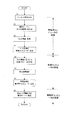
以上のようなハードウェアとソフトウェアの構成による蒸着処理の手順について、図5を参照しながら以下に説明する。 The procedure of the vapor deposition process by the above hardware and software configuration will be described below with reference to FIG.
まず、ステップS1では管理用コンピュータ1が、作業指示書21のバーコードからレンズ20のIDを読み込む。次に、ステップS2、S3では、管理用コンピュータ1のデータベースクライアント112が、レンズ20のIDをロット番号として、管理サーバ7aのデータベース8aにIDを問い合わせ、このIDに対応するロット情報(加工指示)を取得する。このロット情報には、蒸着処理を行う当該ロット番号の薄膜の層数、蒸着材料の種類など蒸着処理に関する指令が含まれる。なお、トレーなどに乗せられていた複数のレンズ20は、蒸着装置3のコートドーム30に移動される。
First, in step S <b> 1, the
次に、ステップS4では、データベースクライアント112が管理サーバ7aから得たロット情報を、通信ソフトウェア113を介して制御コンピュータ2へ送信する。
Next, in step S4, the database client 112 transmits the lot information obtained from the
次に、ステップS5では、制御コンピュータ2が通信ソフトウェア212を介して管理用コンピュータ1から受信したロット情報から、コートドーム30に設置されたロットの蒸着処理の内容を決定する。ロット情報には、レンズ20の蒸着処理に必要な加工指示が含まれているので、制御ソフトウェア211では、このロット情報に基づいて、予め設定した制御パラメータを決定する。例えば、蒸着材料の種類や形成する薄膜の種類に応じた電子銃の電力等、より細かな制御パラメータを決定する。
Next, in step S <b> 5, the
そして、ステップS6では、制御コンピュータ2は、制御ソフトウェア211が決定した制御パラメータに基づいて、コートドーム30のレンズ20に薄膜を形成する。この際に、例えば、制御ソフトウェア211は薄膜の厚さを検出しながら電子銃の電力を調整するフィードバック制御や、成膜終了判定計算等を行う。
In step S <b> 6, the
ステップS7では、制御ソフトウェア211が、蒸着処理が完了すると管理用コンピュータ1に蒸着処の完了を通知し、さらに、蒸着の結果(各層(薄膜)毎の処理時間、真空度、膜厚)など、予め設定したデータを管理用コンピュータ1に送信する。
In step S7, when the vapor deposition process is completed, the
ステップS8では、管理用コンピュータ1が、制御コンピュータ2から受信した蒸着完了の通知と蒸着の結果をロット番号に関連づけて、サーバ7aのデータベース8aに記録する。また、管理用コンピュータ1の記憶装置103にもロット番号、加工指示及び加工履歴を記録しておく。
In step S8, the
以上の手順により、管理用コンピュータ1と制御コンピュータ2は情報の授受を行って、蒸着装置3の制御を行い、蒸着処理が完了すると、自動的に管理サーバ7aのデータベース8aにロット番号に対応する蒸着結果(加工履歴)が蓄積されていく。
By the above procedure, the
なお、工場Bでも同一の手順で処理が行われ、自動的に管理サーバ7bのデータベース8bにロット番号に対応する蒸着結果が蓄積されていく。
In the factory B, the same procedure is performed, and the deposition result corresponding to the lot number is automatically accumulated in the
そして、管理サーバ7a、7bのデータベース8a、8bを定期的にインターネット10上のサーバ70のデータベース80と同期を取ることで、地理的に異なる工場A、Bのレンズ20の加工履歴を収集することができる。サーバ70のデータベース80にアクセスすることにより、製造したレンズ20の加工履歴をロット番号毎に把握することができ、きめ細かな品質の管理を実現することができる。
Then, by periodically synchronizing the
また、各ロットの加工指示を、ロット番号に基づいて管理サーバ7aのデータベース8aから取得するようにしたので、従来手作業で行っていた、加工指示を自動的に行うことが可能となって、蒸着装置3のオペレータの労力を大幅に低減することができる。
In addition, since the processing instructions for each lot are acquired from the
また、データベース8aまたは各管理用コンピュータ1に保存された蒸着結果は、基本的にいつでも、管理用コンピュータ1上で閲覧可能である。また、ネットワーク11を経由しての閲覧も可能である。したがって、蒸着処理の現場外から、蒸着結果をチェックすることが可能となったことが、作業効率を大幅に向上させることができる。
Moreover, the vapor deposition result preserve | saved in the
以上のように、管理用コンピュータ1上やネットワーク11上のコンピュータからデータベース8aまたはデータベース80へアクセスすることで蒸着結果の閲覧が可能となったことで、生産性のアップ(サイクルタイムの縮小)が期待できる。従来は、制御コンピュータ2における生産中での蒸着結果の閲覧は、蒸着終了時から次の蒸着が始まる前までであった。この束縛条件のために、オペレータは、この合間を狙うか、あるいは、蒸着の開始を遅らせて、蒸着結果を閲覧するという行為に甘んじていた。これは、直接、生産の遅れに繋がる。これに対して本実施形態のように、管理用コンピュータ1で、リアルタイムに蒸着結果を参照でき、蒸着結果の解析処理がいつでも出来るようになったことでオペレータの作業の効率を、大幅に向上させることが可能となったのである。
As described above, the deposition results can be viewed by accessing the
また、管理用コンピュータ1と制御コンピュータ2のデータのやり取りは、上記ステップS4の蒸着処理の開始前と、ステップS7蒸着処理の終了時点の2点であり、蒸着処理中は、管理用コンピュータ1と制御コンピュータ2の間で通信を行う必要がない。したがって、制御コンピュータ2では、リソースを制御ソフトウェア211に提供することができ、蒸着処理の制御精度を確保できるのである。
Further, the exchange of data between the
以上のように、本実施形態によれば、ネットワーク11に接続されてデータベース8aとの通信を行う管理用コンピュータ1と、蒸着装置3の制御を実行する制御コンピュータ2を論理的な仕様(通信手順)で分けて、管理用コンピュータ1と制御コンピュータ2を接続する通信手段5を、ネットワーク11とは物理的(例えば、RS232C)及び論理的(独自の通信プロトコル)に異なる規格を採用し、ネットワーク11に直接接続される管理用コンピュータ1にはアンチウイルスソフトウェア111を実行させておき、管理用コンピュータ1に接続された制御コンピュータ2には、アンチウイルスソフトウェアをインストールせず、制御ソフトウェア211と通信ソフトウェア212を実行させておく。
As described above, according to the present embodiment, the
これにより、管理用コンピュータ1に不正なコードが侵入すると、アンチウイルスソフトウェア111により駆除が行われる。万一、不正なコードの定義に存在しない未知のウイルスまたはワーム等の不正なコードが管理用コンピュータ1に侵入した場合、管理用コンピュータ1はこの不正なコードに感染する。しかし、不正なコードは、TCP/IPなどネットワーク11側以外の通信手段を通過する仕組みを備えていないため、通信手段5から制御コンピュータ2へ侵入することはできない。
As a result, when an illegal code enters the
したがって、仮に、管理用コンピュータ1が不正なコードに感染したとしても、制御コンピュータ2は影響を受けることなく蒸着処理を継続することが可能となって、現在処理中のロットを無駄にすることはなく、かつ、制御コンピュータ2のシステムが破壊される恐れがないため、生産性を維持することができるのである。
Therefore, even if the
さらに、制御コンピュータ2には、レンズの加工を行う制御定数など部外者などに閲覧されたくない情報が多数格納されているが、管理用コンピュータ1と制御コンピュータ2の通信手順を、管理用コンピュータ1のネットワーク11側とは異なる通信手順とすることにより、制御コンピュータ2の情報を閲覧することは極めて困難となり、制御コンピュータ2のセキュリティを向上させることが可能となる。
Further, the
特に、制御コンピュータ2と管理用コンピュータ1の通信手順に独自の通信プロトコルを適用すれば、第3者がネットワーク11側から管理用コンピュータ1に侵入しても、制御コンピュータ2の情報を閲覧することは完全に不可能となり、制御コンピュータ2のセキュリティをさらに向上させることが可能となる。
In particular, if a unique communication protocol is applied to the communication procedure between the
なお、上記実施形態において、蒸着装置3と制御コンピュータ2及び管理用コンピュータ1を一対一で配置した例を示したが、図6で示すように、一つの管理用コンピュータ1に複数の通信インターフェイス105を設け、各インターフェイス毎に通信手段5を介して制御コンピュータ2、2a、2bと接続しても良い。
In the above embodiment, the
あるいは、図7で示すように、制御コンピュータ2に複数のインターフェイス205を設けて、各インターフェイス205毎に蒸着装置3、3a、3bを接続しても良い。
Alternatively, as shown in FIG. 7, a plurality of
また、図8で示すように、制御コンピュータ2〜2b同士を接続するとともに、他のネットワークから独立したエンジニアリング用ネットワーク110を設け、加工履歴よりもさらに詳しいデータについては、エンジニアリング用ネットワーク110に接続された専用のコンピュータ111から参照するようにしても良い。
Further, as shown in FIG. 8, the
また、上記実施形態においては、通信手段5としてRS232Cを採用した例を示したが、通信手段5としてPIO(Parallel I/O)、USB(Universal Sereal Bus)あるいはIEEE1394等を採用しても、独自の通信プロトコルを用いるのであれば何でも良い。したがって、管理用コンピュータ1と制御コンピュータ2を接続する通信手段にイーサネット(登録商標)を用いて、ネットワーク11側の通信手順(TCP/IP)とは異なる通信手順を用いるようにしても良い。
In the above-described embodiment, an example in which RS232C is adopted as the communication means 5 is shown. However, even if PIO (Parallel I / O), USB (Universal Sereal Bus), IEEE1394, or the like is adopted as the communication means 5, it is unique. Any communication protocol can be used. Therefore, Ethernet (registered trademark) may be used as a communication means for connecting the
なお、上記実施形態では、蒸着工程に本発明を適用した例を示したが、レンズ成型工程や染色工程、ディップコート工程などに適用することができる。 In the above embodiment, an example in which the present invention is applied to the vapor deposition process has been described. However, the present invention can be applied to a lens molding process, a dyeing process, a dip coating process, and the like.
また、上記実施形態では、眼鏡用レンズに適用した例を示したが、他の光学系のレンズ(例えば、DVD−ROMやCD−ROMなどの光学ドライブやカメラのレンズなど)の製造システムに適用することもできる。 Moreover, although the example applied to the lens for spectacles was shown in the said embodiment, it applies to the manufacturing system of lenses (for example, optical drives, such as DVD-ROM and CD-ROM, a camera lens, etc.) of other optical systems. You can also
また、上記実施形態においては、不正なコードを検出し、駆除するアンチウイルスソフトウェア111を示したが、不正なコードの検出及び駆除に加えて、不正または不要な通信を遮断するファイアーウォール機能を備えるものであっても良い。
In the above-described embodiment, the
また、上記実施形態においては、不正なコードを検出し、駆除するアンチウイルスソフトウェア111を示したが、ハードウェアにより不正なコードを検出し、駆除するようにしても良い。
In the above embodiment, the
また、上記実施形態においては、作業指示書21にレンズの識別子を付したが、図示はしないが、不揮発性のメモリを備えたICカードなどに識別子を記憶させてもよい。この場合、バーコードリーダ61に代わってICカードリーダを管理用コンピュータ1に設ければよい。
In the above-described embodiment, the lens identifier is attached to the
また、上記実施形態においては、工場Aのネットワーク11と工場Bのネットワーク11をインターネット10に接続する例を示したが、インターネット10に代わって、WAN(Wide Area Network)やMAN(Metropolitan Area Network)、あるいは専用線などを用いて工場A、Bのネットワーク11、12を接続するようにしても良い。
In the above embodiment, an example in which the
以上のように、本発明によれば、製造工程におけるトレーサビリティの確保と、製造装置のコンピュータウイルスに対する脆弱性の克服とを両立でき、信頼性に優れたレンズの生産システムに適用することができる。 As described above, according to the present invention, it is possible to achieve both of ensuring traceability in the manufacturing process and overcoming vulnerability to the computer virus of the manufacturing apparatus, and can be applied to a lens production system having excellent reliability.
1 管理用コンピュータ
2 制御コンピュータ
3 蒸着装置
5 通信手段
7a、7b 管理サーバ
8a、8b データベース
10 インターネット
11 ネットワーク
20 レンズ
111 アンチウイルスソフトウェア
DESCRIPTION OF
Claims (4)
レンズに所定の加工を施す加工装置と、
前記加工装置を制御する第2のコンピュータと、を備えて前記製品管理情報に基づいてレンズの加工を行うレンズの製造システムにおいて、
複数のコンピュータに接続されたネットワークと、
前記第1のコンピュータに設けられて前記ネットワークと第1の通信手順を用いて通信を行う第1の通信インターフェースと、
前記第1のコンピュータと第2のコンピュータとを接続する通信手段と、
前記第1及び第2のコンピュータにそれぞれ設けられて、前記通信手段を介して第2の通信手順により通信を行う第2の通信インターフェースと、
前記第1のコンピュータに設けられて、レンズの識別子を読み込むレンズ情報取得手段と、
前記第1のコンピュータに設けられて、前記識別子に対応する加工指示を前記データベースから取得し、前記第2の通信インターフェースを介して前記第2のコンピュータに送信する加工指示送信手段と、
前記第2のコンピュータに設けられて、前記加工指示に基づいてレンズに所定の加工を施した後、前記第2の通信インターフェースを介して加工の結果を前記第1のコンピュータへ送信する加工制御手段と、
前記第1のコンピュータに設けられて、前記第2のコンピュータから受信した加工の結果を、前記識別子に関連づけて前記データベースに記録するデータベース更新手段と、
前記第1のコンピュータに設けられて、不正なコードを検出し、駆除するアンチウイルス手段と、
前記ネットワークに接続されて、レンズの製造にかかる前記製品管理情報を管理するデータベースを実行する管理サーバと、
を備え、
前記所定の加工は蒸着処理であって、
前記加工指示送信手段は、前記蒸着処理の開始前に前記加工指示を前記第2のコンピュータに送信し、
前記加工制御手段は、前記蒸着処理の終了時点に前記加工の結果を前記第1のコンピュータへ送信し、
前記第1のコンピュータは、前記データベースのクライアントであって、
前記加工指示送信手段は、前記識別子に対応する加工指示を前記データベースに問い合わせ、前記データベースから当該識別子に対応する加工指示を取得して、当該加工指示を前記第2のコンピュータに送信し、
前記第1のコンピュータの前記データベース更新手段は、第2のコンピュータから受信した加工の結果とレンズの識別子を関連づけて、前記データベースに記録することを特徴とするレンズの製造システム。 A first computer capable of accessing a database for managing product management information including processing instructions and processing results for manufacturing a lens;
A processing device for performing predetermined processing on the lens;
A lens manufacturing system comprising: a second computer for controlling the processing device; and processing the lens based on the product management information;
A network connected to multiple computers;
A first communication interface provided in the first computer for communicating with the network using a first communication procedure;
Communication means for connecting the first computer and the second computer;
A second communication interface that is provided in each of the first and second computers and performs communication according to a second communication procedure via the communication unit;
Lens information acquisition means provided in the first computer for reading an identifier of a lens;
A processing instruction transmitting means provided in the first computer for acquiring a processing instruction corresponding to the identifier from the database and transmitting the processing instruction to the second computer via the second communication interface;
A processing control unit provided in the second computer, which performs predetermined processing on the lens based on the processing instruction and then transmits a processing result to the first computer via the second communication interface. When,
A database updating means provided in the first computer for recording the processing result received from the second computer in the database in association with the identifier;
An anti-virus means provided in the first computer for detecting and removing malicious code;
A management server connected to the network and executing a database for managing the product management information related to the manufacture of the lens;
With
The predetermined process is a vapor deposition process,
The processing instruction transmission means transmits the processing instruction to the second computer before the start of the vapor deposition process,
The processing control means transmits the processing result to the first computer at the end of the vapor deposition process ,
The first computer is a client of the database;
The processing instruction transmission means inquires of the database for a processing instruction corresponding to the identifier, acquires a processing instruction corresponding to the identifier from the database, and transmits the processing instruction to the second computer,
The lens update system of the first computer is characterized in that the processing result received from the second computer and a lens identifier are associated with each other and recorded in the database .
前記広域ネットワークには、複数の工場内ネットワークに接続された前記管理サーバを統合する上位の管理サーバが接続され、当該上位の管理サーバは、前記管理サーバのデータベースを統合する上位のデータベースを備えたことを特徴とする請求項1に記載のレンズの製造システム。 The network is a network connecting computers in a factory, and the network is connected to a wide area network capable of communicating with geographically distant computers.
An upper management server that integrates the management servers connected to a plurality of factory networks is connected to the wide area network, and the upper management server includes an upper database that integrates the databases of the management servers. The lens manufacturing system according to claim 1.
Priority Applications (1)
| Application Number | Priority Date | Filing Date | Title |
|---|---|---|---|
| JP2004226270A JP4491296B2 (en) | 2004-08-03 | 2004-08-03 | Lens manufacturing system |
Applications Claiming Priority (1)
| Application Number | Priority Date | Filing Date | Title |
|---|---|---|---|
| JP2004226270A JP4491296B2 (en) | 2004-08-03 | 2004-08-03 | Lens manufacturing system |
Publications (2)
| Publication Number | Publication Date |
|---|---|
| JP2006050111A JP2006050111A (en) | 2006-02-16 |
| JP4491296B2 true JP4491296B2 (en) | 2010-06-30 |
Family
ID=36028180
Family Applications (1)
| Application Number | Title | Priority Date | Filing Date |
|---|---|---|---|
| JP2004226270A Active JP4491296B2 (en) | 2004-08-03 | 2004-08-03 | Lens manufacturing system |
Country Status (1)
| Country | Link |
|---|---|
| JP (1) | JP4491296B2 (en) |
Families Citing this family (3)
| Publication number | Priority date | Publication date | Assignee | Title |
|---|---|---|---|---|
| EP2175405A1 (en) * | 2008-10-10 | 2010-04-14 | Essilor International (Compagnie Générale D'Optique) | A processing device for processing an order request of an ophtalmic lens |
| EP2590114A1 (en) * | 2011-11-03 | 2013-05-08 | Essilor International (Compagnie Générale D'Optique) | Secured data communication in a networked computer system for providing optical lenses |
| JP2014021667A (en) * | 2012-07-17 | 2014-02-03 | Disco Abrasive Syst Ltd | Management method for processing device |
Citations (4)
| Publication number | Priority date | Publication date | Assignee | Title |
|---|---|---|---|---|
| JP2001292176A (en) * | 2000-04-10 | 2001-10-19 | Fuji Electric Co Ltd | Gateway device and method for integrating control/ information network |
| JP2002027567A (en) * | 2000-07-12 | 2002-01-25 | Hitachi Kokusai Electric Inc | Remote operation system of semiconductor manufacturing apparatus, semiconductor manufacturing apparatus, and remote operation device |
| JP2002072516A (en) * | 2000-08-29 | 2002-03-12 | Kyocera Mita Corp | Coating device of photoreceptor drum |
| WO2003098181A1 (en) * | 2002-05-16 | 2003-11-27 | Hoya Corporation | Method and device for evaluating spectacle lens or mold for molding spectacle lens, and method and system for manufacturing spectacle lens |
Family Cites Families (3)
| Publication number | Priority date | Publication date | Assignee | Title |
|---|---|---|---|---|
| JP2928543B2 (en) * | 1989-07-19 | 1999-08-03 | 株式会社日立製作所 | Method for forming hard coat film on plastic member |
| JPH03188269A (en) * | 1989-12-15 | 1991-08-16 | Shin Meiwa Ind Co Ltd | Device for melting vapor depositing material of vapor deposition device |
| JPH10112714A (en) * | 1996-10-08 | 1998-04-28 | Hitachi Ltd | Communication converter |
-
2004
- 2004-08-03 JP JP2004226270A patent/JP4491296B2/en active Active
Patent Citations (4)
| Publication number | Priority date | Publication date | Assignee | Title |
|---|---|---|---|---|
| JP2001292176A (en) * | 2000-04-10 | 2001-10-19 | Fuji Electric Co Ltd | Gateway device and method for integrating control/ information network |
| JP2002027567A (en) * | 2000-07-12 | 2002-01-25 | Hitachi Kokusai Electric Inc | Remote operation system of semiconductor manufacturing apparatus, semiconductor manufacturing apparatus, and remote operation device |
| JP2002072516A (en) * | 2000-08-29 | 2002-03-12 | Kyocera Mita Corp | Coating device of photoreceptor drum |
| WO2003098181A1 (en) * | 2002-05-16 | 2003-11-27 | Hoya Corporation | Method and device for evaluating spectacle lens or mold for molding spectacle lens, and method and system for manufacturing spectacle lens |
Also Published As
| Publication number | Publication date |
|---|---|
| JP2006050111A (en) | 2006-02-16 |
Similar Documents
| Publication | Publication Date | Title |
|---|---|---|
| JP6624692B2 (en) | Analysis of cyber security risks in industrial control environments | |
| EP2849066B1 (en) | Anonymous decisions in an access control system | |
| JP4168052B2 (en) | Management server | |
| US20060236374A1 (en) | Industrial dynamic anomaly detection method and apparatus | |
| US20170237752A1 (en) | Prediction of potential cyber security threats and risks in an industrial control system using predictive cyber analytics | |
| CN113625665B (en) | Centralized security event generation policies | |
| EP2765466B1 (en) | A method for user management and a power plant control system thereof for a power plant system | |
| JP2008015786A (en) | Access control system and access control server | |
| EP3085013B1 (en) | Intelligent firewall access rules | |
| US20160226912A1 (en) | Endpoint policy change | |
| US20210136088A1 (en) | Method and system for managing iot-based devices in an internet-of-things environment | |
| GB2590547A (en) | Personnel profiles and fingerprint authentication for configuration engineering and runtime applications | |
| KR102247938B1 (en) | Method and arrangement to control data exchange of an industrial edge device | |
| RU2746101C2 (en) | System and method of network unit definition using rules of inventory | |
| US11683336B2 (en) | System and method for using weighting factor values of inventory rules to efficiently identify devices of a computer network | |
| JP2006066982A (en) | Network connection control system | |
| JP4491296B2 (en) | Lens manufacturing system | |
| KR102206847B1 (en) | System and method for hybrid security | |
| CN101800752A (en) | Method and system for improving safety and performance of domain name system (DNS) | |
| CN113625664B (en) | Automatic endpoint security policy allocation through zero-contact registration | |
| KR100503772B1 (en) | A monitoring system and method of auditing performanced work connected to database server by utility method | |
| JP7225958B2 (en) | Controllers and control systems | |
| KR100431209B1 (en) | Network Management Method using Managing Sensors | |
| JP2007151114A (en) | Communication system, communication terminal with virtual network switch and portable electronic device with biological recognition apparatus | |
| CN201717899U (en) | System for improving safety and performance of domain name system |
Legal Events
| Date | Code | Title | Description |
|---|---|---|---|
| A621 | Written request for application examination |
Free format text: JAPANESE INTERMEDIATE CODE: A621 Effective date: 20070521 |
|
| A977 | Report on retrieval |
Free format text: JAPANESE INTERMEDIATE CODE: A971007 Effective date: 20090519 |
|
| A131 | Notification of reasons for refusal |
Free format text: JAPANESE INTERMEDIATE CODE: A131 Effective date: 20090526 |
|
| A521 | Written amendment |
Free format text: JAPANESE INTERMEDIATE CODE: A523 Effective date: 20090727 |
|
| A02 | Decision of refusal |
Free format text: JAPANESE INTERMEDIATE CODE: A02 Effective date: 20091201 |
|
| A521 | Written amendment |
Free format text: JAPANESE INTERMEDIATE CODE: A523 Effective date: 20100301 |
|
| A911 | Transfer to examiner for re-examination before appeal (zenchi) |
Free format text: JAPANESE INTERMEDIATE CODE: A911 Effective date: 20100308 |
|
| TRDD | Decision of grant or rejection written | ||
| A01 | Written decision to grant a patent or to grant a registration (utility model) |
Free format text: JAPANESE INTERMEDIATE CODE: A01 Effective date: 20100330 |
|
| A01 | Written decision to grant a patent or to grant a registration (utility model) |
Free format text: JAPANESE INTERMEDIATE CODE: A01 |
|
| A61 | First payment of annual fees (during grant procedure) |
Free format text: JAPANESE INTERMEDIATE CODE: A61 Effective date: 20100405 |
|
| FPAY | Renewal fee payment (event date is renewal date of database) |
Free format text: PAYMENT UNTIL: 20130409 Year of fee payment: 3 |
|
| R150 | Certificate of patent or registration of utility model |
Free format text: JAPANESE INTERMEDIATE CODE: R150 |
|
| FPAY | Renewal fee payment (event date is renewal date of database) |
Free format text: PAYMENT UNTIL: 20130409 Year of fee payment: 3 |
|
| FPAY | Renewal fee payment (event date is renewal date of database) |
Free format text: PAYMENT UNTIL: 20140409 Year of fee payment: 4 |
|
| R250 | Receipt of annual fees |
Free format text: JAPANESE INTERMEDIATE CODE: R250 |
|
| R250 | Receipt of annual fees |
Free format text: JAPANESE INTERMEDIATE CODE: R250 |
|
| R250 | Receipt of annual fees |
Free format text: JAPANESE INTERMEDIATE CODE: R250 |
|
| R250 | Receipt of annual fees |
Free format text: JAPANESE INTERMEDIATE CODE: R250 |
|
| R250 | Receipt of annual fees |
Free format text: JAPANESE INTERMEDIATE CODE: R250 |
|
| R250 | Receipt of annual fees |
Free format text: JAPANESE INTERMEDIATE CODE: R250 |