JP4481125B2 - Display device - Google Patents
Display device Download PDFInfo
- Publication number
- JP4481125B2 JP4481125B2 JP2004272242A JP2004272242A JP4481125B2 JP 4481125 B2 JP4481125 B2 JP 4481125B2 JP 2004272242 A JP2004272242 A JP 2004272242A JP 2004272242 A JP2004272242 A JP 2004272242A JP 4481125 B2 JP4481125 B2 JP 4481125B2
- Authority
- JP
- Japan
- Prior art keywords
- wedge
- light
- sheet
- lens
- display device
- Prior art date
- Legal status (The legal status is an assumption and is not a legal conclusion. Google has not performed a legal analysis and makes no representation as to the accuracy of the status listed.)
- Active
Links
Images


Landscapes
- Optical Elements Other Than Lenses (AREA)
- Liquid Crystal (AREA)
- Devices For Indicating Variable Information By Combining Individual Elements (AREA)
Description
本発明は、ディスプレイの前面に設置し、ディスプレイの性能、特に、ディスプレイに外光が当たった時のコントラスト低下等による性能の低下を防止する機能や、ディスプレイの有効光を好適に拡散させて視野角を広くする機能等を有するコントラスト向上シートを用いた表示装置に関するものである。 The present invention is installed on the front face of a display, and the display performance, in particular, a function for preventing a decrease in performance due to a decrease in contrast when external light hits the display, and a visual field by suitably diffusing the effective light of the display. it relates a display device using a contrast enhancing sheet having a function for widening the angle.
有機発光ダイオード・ディスプレイ(以下、OLEDと記す。)や液晶ディスプレイ(以下、LCDと記す。)等では、通常、観察者がどのような位置から見ても良好な画像が得られるように、視野角が広いことが好まれる。
一方、例えば通勤電車の中で仕事をする場合等、周りの人から画面を覗かれては困ることがあり、このような場合にはディスプレイの観察者のみに見え、他人からは見えないような視野角の制御が望まれる。このような要求に対して、例えば図10に示すようなルーバータイプのコントラスト向上シートが開発されて使用されている。ルーバータイプのコントラスト向上シートは、外光を遮光してコントラストを上げる効果を示し、例えば、ルーバーにおける二重像(ゴーストと称する。)の発生を減少させたコントラスト向上シートが開示されている(特許文献1〜特許文献3参照。)。特許文献1の第5図には、ゴーストの説明図が記載されている。
On the other hand, for example, when working on a commuter train, it may be difficult to see the screen from people around you. In such a case, it will be visible only to the viewer of the display and not to others. Control of the viewing angle is desired. In response to such a demand, for example, a louver type contrast enhancing sheet as shown in FIG. 10 has been developed and used. The louver type contrast improving sheet has an effect of increasing the contrast by blocking outside light, and for example, a contrast improving sheet is disclosed in which occurrence of a double image (referred to as a ghost) in the louver is reduced (patent).
しかし、特許文献1〜特許文献3に記載されたルーバータイプの従来のコントラスト向上シートは、斜め方向の映像光を単純にカットしており、高精細LCD等のディスプレイにおいては、観察者側に到達させるべき映像側の拡散光源の拡散光を減少させてしまい、画面の輝度が低下するという問題があった。
However, the conventional louver type contrast enhancement sheet described in
そこで、本発明は、外光による画像のコントラスト低下を抑制し、コントラストを向上することを第1の目的とし、さらにゴーストの発生を抑えて、映像源からの拡散光を有効に利用して画面の輝度の低下を抑制し、適正な視野角を有するコントラスト向上シートを備える表示装置を提供することを課題とする。 Accordingly, the present invention has a first object of suppressing a decrease in contrast of an image due to external light and improving the contrast, and further suppressing the occurrence of a ghost and effectively using diffused light from a video source. It is an object of the present invention to provide a display device including a contrast improving sheet that suppresses a decrease in luminance and has an appropriate viewing angle.
以下、本発明について説明する。なお、本発明の理解を容易にするために添付図面の参照符号を付記するが、それにより本発明が図示の形態に限定されるものではない。 The present invention will be described below. In addition, in order to make an understanding of this invention easy, the referential mark of an accompanying drawing is appended, but this invention is not limited to the form of illustration by it.
請求項1の発明は、映像光を発する映像源と、前記映像源よりも観察者側に配置されるコントラスト向上シートとを備える表示装置であって、前記コントラスト向上シートは、断面形状が台形のレンズ部が所定の間隔で配列されるとともに、隣り合う前記レンズ部間の楔形部は、前記レンズ部と、同一又は異なる材料が充填され、前記楔形部は、映像源側もしくは観察者側に先端を有し、かつ、光吸収効果を有し、前記コントラスト向上シートを構成するシートの最も映像源側であるシート面に、プリズムレンズが設けられ、前記プリズムレンズは、前記シート面を底面とする三角柱プリズムが配列されており、前記三角柱プリズムが前記底面となす角度が、法線を上向きに持つ5°〜20°の緩斜面と法線を下向きに持つ50°〜90°の急斜面とを備えることを特徴とする表示装置である。
本発明においては、プリズムレンズは連続プリズム形状がより好ましい。
本発明においては、観察者に好ましい上方の適正な視野角を30°〜60°と設定し、それに対応してプリズムレンズの緩斜面の角度を定めている。
すなわち、視野角を30°とするとプリズムレンズの緩斜面の角度は約20°、視野角45°とすると緩斜面の角度は約12°、視野角60°とすると緩斜面の角度は約5°となる。
また、本発明において、プリズムレンズの角度を変えて、上側を緩斜面、下側を急斜面とするのは、外光は上方から入射する場合が多く、それをシート裏面のプリズムレンズで効果的に反射させ、楔形部で吸収し、観察者側に行かせないようにするためである。
本発明において、プリズムレンズの急斜面の角度は、プリズムレンズ製造上の制約とコントラスト向上効果により好ましい角度範囲が設定される。
プリズムレンズの急斜面の角度が、90°を超えるとレンズの製造が困難となり、50°未満ではコントラストが低下する。
上記のように、上方から入射した外光は、プリズムレンズで反射されて楔形部で吸収され、コントラストが向上する。
一方、映像源側からの映像光はプリズムレンズにより若干下向きになるが、指向性の少ない拡散光を用いるディスプレイの場合には、視野角にはほとんど影響しない。
The invention of
In the present invention, the prism lens is more preferably a continuous prism shape.
In the present invention, an appropriate upper viewing angle preferable for an observer is set to 30 ° to 60 °, and the angle of the gentle slope of the prism lens is determined correspondingly.
That is, if the viewing angle is 30 °, the angle of the gentle slope of the prism lens is about 20 °, if the viewing angle is 45 °, the angle of the gentle slope is about 12 °, and if the viewing angle is 60 °, the angle of the gentle slope is about 5 °. It becomes.
Further, in the present invention, the angle of the prism lens is changed so that the upper side is a gentle slope and the lower side is a steep slope. This is because the light is reflected and absorbed by the wedge-shaped portion so that it does not go to the viewer side.
In the present invention, the angle of the steep slope of the prism lens is set to a preferable angle range due to the prism lens manufacturing restrictions and the contrast improvement effect.
If the angle of the steep slope of the prism lens exceeds 90 °, it is difficult to manufacture the lens, and if it is less than 50 °, the contrast decreases.
As described above, external light incident from above is reflected by the prism lens and absorbed by the wedge-shaped portion, and the contrast is improved.
On the other hand, the image light from the image source side is slightly lowered by the prism lens, but in the case of a display using diffused light with less directivity, the viewing angle is hardly affected.
請求項2の発明は、請求項1に記載の表示装置において、前記プリズムレンズは垂直方向に光を制御することを特徴とする。
A second aspect of the present invention, in the display device according to
請求項3の発明は、請求項1又は2に記載の表示装置において、前記楔形部の断面形状が観察者側に幅広の下底面を有する略台形であることを特徴とする。
楔形部を略等脚台形とすることにより、楔形部の上底面の頂角が鈍角となり、楔形部を作製するための金型等が容易に製造でき、さらに楔形部の強度が向上し、高品質のコントラスト向上シートを安定して製造することができる。
According to a third aspect of the present invention, in the display device according to the first or second aspect , the cross-sectional shape of the wedge-shaped portion is a substantially trapezoid having a wide bottom surface on the viewer side.
By making the wedge-shaped part into a substantially isosceles trapezoidal shape, the apex angle of the upper and bottom surfaces of the wedge-shaped part becomes obtuse, making it possible to easily manufacture a mold for producing the wedge-shaped part, and further improving the strength of the wedge-shaped part. It is possible to stably produce a quality-enhanced sheet.
請求項4の発明は、請求項1〜3のいずれか1項に記載の表示装置において、前記楔形部の斜面部分が出光面の法線となす角度をθとしたとき、θが0°〜15°の範囲であることを特徴とする。
本発明においては、映像光を楔形部の斜面で反射し、視野角を広くするために、上記の角度範囲を好ましい角度としている。
角度θが15°を超えると、十分なコントラスト向上効果もしくは視野角制御効果を達成するために、ブラックストライプBSの幅を広くする必要が生じるので、光の利用効率が低下し、輝度が低下してしまう。
さらに、BS幅が広いと製造がより難しくなるという問題を生じる。
また、本発明においては、断面形状楔形部の斜面部分が出光面の法線となす角度θは、必ずしも楔形部の上下で同一角度である必要はなく、上下の角度が0°〜15°の範囲内において、例えば、0°と10°のように、異なる角度を有することも可能である。
According to a fourth aspect of the present invention, in the display device according to any one of the first to third aspects, when the angle formed by the inclined surface portion of the wedge-shaped portion and the normal line of the light emitting surface is θ, θ is 0 ° to The range is 15 °.
In the present invention, in order to reflect the image light on the slope of the wedge-shaped portion and widen the viewing angle, the above angle range is set as a preferable angle.
If the angle θ exceeds 15 °, it is necessary to widen the width of the black stripe BS in order to achieve a sufficient contrast enhancement effect or viewing angle control effect, so that the light use efficiency is lowered and the luminance is lowered. End up.
Further, when the BS width is wide, there arises a problem that manufacture becomes more difficult.
In the present invention, the angle θ formed by the slope portion of the cross-sectional wedge-shaped portion and the normal line of the light exit surface does not necessarily have to be the same angle above and below the wedge-shaped portion, and the vertical angle is 0 ° to 15 °. It is also possible to have different angles within the range, for example 0 ° and 10 °.
請求項5の発明は、請求項1〜4のいずれか1項に記載の表示装置において、前記楔形部の少なくとも斜面部分を構成する材料の屈折率Nxと、前記レンズ部を構成する材料の屈折率Nyとの間に
Nx−Ny≧−0.01
なる関係を有することを特徴とする。
本発明において、屈折率Nxと屈折率Nyとの屈折率差をほとんどなくすことにより、楔形部に小さい角度で入射した光は全反射せずに楔形部に吸収され、実質的にゴーストの発生が抑えられる。
Nx−Ny=−0.01の場合は、斜面に対して約84°以上の角度で入射する映像光は全反射するが、この範囲であれば実質的に問題となるレベルのゴーストにはならない。
Nx−Nyが−0.01未満では、観察者側の位置の10°〜30°辺りにゴーストの影響が生じてきて好ましくない。
According to a fifth aspect of the present invention, in the display device according to any one of the first to fourth aspects, the refractive index Nx of the material constituting at least the slope portion of the wedge-shaped portion and the refraction of the material constituting the lens portion. Nx−Ny ≧ −0.01 between the rate Ny
It has the relationship which becomes.
In the present invention, by eliminating the refractive index difference between the refractive index Nx and the refractive index Ny, light incident on the wedge-shaped portion at a small angle is absorbed by the wedge-shaped portion without being totally reflected, and a ghost is substantially generated. It can be suppressed.
In the case of Nx−Ny = −0.01, the image light incident at an angle of about 84 ° or more with respect to the inclined surface is totally reflected. However, if it is within this range, the ghost does not substantially cause a problem level. .
If Nx−Ny is less than −0.01, the influence of ghost is generated around 10 ° to 30 ° on the observer side, which is not preferable.
請求項6の発明は、請求項1〜5のいずれか1項に記載の表示装置において、前記楔形部に光吸収粒子が添加されていることを特徴とする。 A sixth aspect of the present invention is the display device according to any one of the first to fifth aspects, wherein light absorbing particles are added to the wedge-shaped portion.
請求項7の発明は、請求項6に記載の表示装置において、前記楔形部が略台形であって、前記光吸収粒子の平均粒径が1μm以上で、前記略台形の上底面の幅以下であることを特徴とする。
The invention according to
請求項8の発明は、請求項6又は7に記載の表示装置において、前記光吸収粒子の添加量が10〜50体積%であることを特徴とする。
The invention according to
請求項9の発明は、請求項1〜8のいずれか1項に記載の表示装置において、前記コントラスト向上シートは、少なくとも一面側に、AR、AS、AG、タッチセンサーのうちのいずれか、又はこれらの内複数の付加機能が付与されていることを特徴とする。
The invention according to
請求項10の発明は、請求項1〜9のいずれか1項に記載の表示装置において、前記楔形部の2つの斜面部分が出光面の法線となす各々の角度が異なっていることを特徴とする。 A tenth aspect of the present invention is the display device according to any one of the first to ninth aspects, wherein the angles formed by the two inclined surface portions of the wedge-shaped portion and the normal line of the light exit surface are different. to.
請求項11の発明は、請求項10に記載の表示装置において、前記楔形部の2つの斜面部分が前記出光面の法線となす各々の角度は、上側の角度が下側の角度より大きいことを特徴とする。
The invention of
請求項12の発明は、請求項1〜11のいずれか1項に記載の表示装置において、前記コントラスト向上シートを、前記断面形状が台形の前記レンズ部が横ストライプとなる形態で用いることを特徴とするものである。
The invention of
本発明によれば、断面形状が台形のレンズ部が所定の間隔で配列されるとともに、隣り合うレンズ部間の楔形部の断面形状を観察者側に幅広の下底面を有する略台形とすることにより、楔形部の製造が容易であり、楔形部の強度が向上した高品質のコントラスト向上シートを得ることができる。また本発明のコントラスト向上シートによれば、映像源からの拡散光を有効に利用して画面の輝度の低下を抑制し、適正な視野角を有し、かつ、ゴーストの発生が抑えられたコントラスト向上シートを得ることができる。また本発明によれば、外光による画像のコントラスト低下を抑制させることができ、特に上方からの外光に対して明室コントラストの向上したコントラスト向上シートが得られる。 According to the present invention, the lens portions having a trapezoidal cross-sectional shape are arranged at a predetermined interval, and the cross-sectional shape of the wedge-shaped portion between adjacent lens portions is a substantially trapezoid having a wide bottom surface on the viewer side. As a result, a wedge-shaped part can be easily manufactured, and a high-quality contrast improving sheet with improved wedge-shaped part strength can be obtained. Further, according to the contrast improving sheet of the present invention, it is possible to effectively reduce the brightness of the screen by effectively using the diffused light from the image source, to have a proper viewing angle, and to suppress the occurrence of the ghost. An improvement sheet can be obtained. Further, according to the present invention, it is possible to suppress a decrease in the contrast of an image due to external light, and it is possible to obtain a contrast-enhancement sheet in which bright room contrast is improved with respect to external light from above.
以下本発明の実施形態につき、図面を参照しながら説明する。 Hereinafter, embodiments of the present invention will be described with reference to the drawings.
(第一の実施形態)
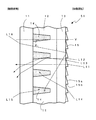
図1は、本発明の第一の実施形態にかかるコントラスト向上シートS1の一方向の断面を示す図である。図1においては、図面右側に映像光源が配置されて拡散光が出射され、図面の左側に観察者が位置している。このコントラスト向上シートS1は、観察者側から映像源方向に順に、観察者側ベースシート11、レンズ部12、映像源側ベースシート13が貼り合わされて形成されており、映像源側ベースシート13の映像源側には連続プリズム形状のプリズムレンズ15が設けられている。レンズ部12は、屈折率がN1の物質で形成されている。さらに、図では上下に隣接する2つのレンズ部12の斜辺に挟まれた部分の断面形状は楔形部をなし、レンズ部12と同一又は異なる材料物質が充填され、屈折率N2を有する物質で埋められている。以後の説明においてはこの屈折率N2の物質で埋められている部分を「楔形部14」という。楔形部14の断面形状は、映像源からの拡散光を効率良く全反射するために、略三角形又は略台形をなすものであり、楔形部は映像源側もしくは観察者側に先端を有するものである。図1においては、楔形部14は略台形をなし、観察者側に幅広の下底面、映像源側に先端となる幅の狭い上底面を備えている。
(First embodiment)
FIG. 1 is a view showing a cross section in one direction of the contrast enhancing sheet S1 according to the first embodiment of the present invention. In FIG. 1, an image light source is arranged on the right side of the drawing to emit diffused light, and an observer is located on the left side of the drawing. The contrast enhancing sheet S1 is formed by adhering the observer
レンズ部12は光透過性樹脂で構成され、電離放射線や熱エネルギーで硬化するアクリレート樹脂等を用いることができる。また、楔形部を構成する樹脂としては、レンズ部と同種の樹脂や、シリコンやフッ素が導入された低屈折アクリレート系樹脂等を用いることができる。レンズ部12の屈折率N1と、楔形部14の屈折率N2とは、コントラスト向上シートS1の光学特性を得るために、下記の式(1)に示される所定の範囲に設定されている。
(式1) N2−N1≧−0.01
また、楔形部14とレンズ部12とが接する斜面が、出光面の法線V(当該コントラスト向上シートS1のレンズ部に対する垂直入射光に平行な線)となす角度は所定の角度θ1に形成されている。θ1は0°〜15°の範囲である。
The
(Formula 1) N2-N1 ≧ −0.01
Further, the inclined surface in contact and the
楔形部14は、カーボン等の顔料又は赤、青、黄、黒等の染料にて所定濃度に着色されている。また、観察者側ベースシート11、及び映像源側ベースシート13は、レンズ部12と略同一の屈折率を有する材料にて構成されている。観察者側ベースシート11の外側面には、観察者側にAR、AS、AGうち、少なくとも一の機能を備えている。ここに「AR」とはアンチリフレクションの略で、レンズ表面に入光する光の反射率を抑える機能をいう。また、「AS」とはアンチスタティックの略で、帯電防止の機能をいう。また「AG」とはアンチグレアの略で、レンズの防眩性機能をいう。本第一実施形態にかかるコントラスト向上シートS1においてはこれらの機能の内一つだけを持たせてもよく、また複数の機能を併せ持たせてもよい。
The wedge-shaped
映像源側ベースシート13の映像源側には連続プリズム形状の複数のプリズムレンズ15が紙面に垂直に設けられており、プリズムレンズ15は映像源からの拡散光を屈折させる。すなわち、プリズムレンズ15は垂直方向に光を制御する。プリズムレンズ15は、シート面を底面とする三角柱プリズムが配列されており、三角柱プリズムが映像源ベースシート13の底面となす角度は、法線を上向きに持つ5°〜20°の緩斜面15aと法線を下向きに持つ50°〜90°の急斜面15bとを備えている。
A plurality of
次にコントラスト向上シートS1のレンズ部12内に入光した光の光路について、図1を参照しつつ簡単に説明する。なお、図1において、光L11〜L13及びL14の光路は模式的に示されたものである。いま、映像源側からレンズ部12の中央部付近に入射した光L11は、そのままコントラスト向上シートS1の内部を直進して通過し、観察者に至る。映像源側からレンズ部12の端部付近に垂直に入射した入射光L12は、屈折率N1のレンズ部12と屈折率N2の楔形部14との屈折率差により楔形部14の斜面にて反射され、所定の角度をもって観察者側に出光される。映像源側からレンズ部12の端部付近に角度をもって入射した光L13は、斜面にて反射され、入射時とは反対方向にさらに大きな角度をもって、観察者側に出光される。さらに映像源側から楔形部14の斜面に所定以下の小さな角度をもって入射する光L14は、全反射されることなく楔形部14の内部に入光する。楔形部14は着色されているので、光L14は着色された楔形部14に吸収され、観察者側に至ることはなく、光L14による二重像(ゴースト)を生じない。また、観察者側から楔形部14の底面に入射する外光L15は楔形部14の内部に入光し、光吸収効果を有する楔形部14に吸収される。さらに、観察者側から入射する外光のうち、プリズムレンズ15まで到達する外光L16は、プリズムレンズ15で反射されて楔形部14の内部に入光し、光吸収効果を有する楔形部14に吸収される。
Next, the optical path of the light entering the
比較のため、図9に本発明のプリズムレンズを設けていないコントラスト向上シートS9に入射した外光L95〜L97の光路を示す。観察者側から楔形部の底面に入射する外光95は楔形部の内部に入光し、光吸収効果を有する楔形部に吸収される。レンズ部に垂直に入射する外光L97は映像源側ベースシートから出光する。観察者側から入射した外光のうち、映像源側ベースシートの最も映像源側の界面まで到達した外光L96は、空気との界面で反射されて再びレンズ部92を通り、観察者側から出光する。このため、コントラストが低下する。
For comparison, FIG. 9 shows an optical path of external light L95 to L97 incident on the contrast enhancing sheet S9 not provided with the prism lens of the present invention. External light 95 incident on the bottom surface of the wedge-shaped portion from the observer side enters the wedge-shaped portion and is absorbed by the wedge-shaped portion having a light absorption effect. The external light L97 incident perpendicularly to the lens part is emitted from the image source side base sheet. Of the external light incident from the observer side, the external light L96 that has reached the interface closest to the image source side of the image source side base sheet is reflected at the interface with the air and passes through the
上記の比較に示されるように、本発明のコントラスト向上シートS1は、プリズムレンズを最も映像源側に設けることにより、外光を効率良く吸収し、コントラストを向上させるものである。このようにして輝度、コントラストが高く、かつゴーストが抑えられ、断面方向に視野角を制御することが可能で、適正な視野角を有するコントラスト向上シートS1を得ることができる。 As shown in the above comparison, the contrast enhancing sheet S1 of the present invention is designed to efficiently absorb external light and improve contrast by providing the prism lens closest to the image source. Thus, brightness and contrast are high, ghost is suppressed, the viewing angle can be controlled in the cross-sectional direction, and the contrast enhancing sheet S1 having an appropriate viewing angle can be obtained.
(第二の実施形態)
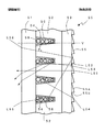
図2は、第二の実施形態にかかるコントラスト向上シートS2の一方向の断面を示す図である。図2においても、図面右側に映像光源が配置され、図面の左側に観察者が位置している。このコントラスト向上シートS2は、観察者側から映像源方向に順に、観察者側ベースシート21、レンズ部22、映像源側ベースシート23が貼り合わされて形成されており、映像源側ベースシート23の映像源側には連続プリズム形状のプリズムレンズ25が設けられている。レンズ部22は、屈折率がN1の物質で形成されている。さらに、図では上下に隣接する2つのレンズ部22の斜面に挟まれた断面形状台形の部分は、屈折率N2を有する物質で埋められている。以後の説明においてはこの屈折率N2の物質で埋められている部分を「楔形部24」という。楔形部24は、観察者側に幅広の下底面、映像側に先端である幅の狭い上底面を備えている。
(Second embodiment)
FIG. 2 is a view showing a cross section in one direction of the contrast improving sheet S2 according to the second embodiment. Also in FIG. 2, an image light source is arranged on the right side of the drawing, and an observer is located on the left side of the drawing. The contrast improving sheet S2 is formed by adhering the observer
レンズ部22の屈折率N1と、楔形部24の屈折率N2とは、コントラスト向上シートS2の光学特性を得るために、上記の式(1)に示される所定の範囲に設定されている。また、楔形部24とレンズ部22とが接する斜面が、出光面の法線V(当該コントラスト向上シートS2の楔形部に対する垂直入射光に平行な線)となす角度は所定の角度θ2 に形成されている。θ2 は0°〜15°の範囲である。
The refractive index N1 of the
楔形部24は、カーボン等の顔料又は所定の染料にて所定濃度に着色されている。また、観察者側ベースシート21、及び映像源側ベースシート23は、レンズ部22と略同一の屈折率を有する材料にて構成されている。観察者側ベースシート21の外側面には、観察者側にAR、AS、AGうち、少なくとも一の機能を備えている。本実施形態においてもこれらの機能の内一つだけを持たせてもよく、また複数の機能を併せ持たせてもよい。
The wedge-shaped
映像源側ベースシート23の映像源側には連続プリズム形状の複数のプリズムレンズ25が紙面に垂直に設けられており、プリズムレンズ25は映像源からの拡散光を屈折させる。すなわち、プリズムレンズ25は垂直方向に光を制御する。プリズムレンズ25は、シート面を底面とする三角柱プリズムが配列されており、三角柱プリズムが映像源ベースシート23の底面となす角度は、法線を上向きに持つ5°〜20°の緩斜面25aと法線を下向きに持つ50°〜90°の急斜面25bとを備えている。
On the image source side of the image source
図示のコントラスト向上シートS2は、楔形部24をなす台形の下底面にブラックストライプBSが形成されている。また、楔形部24の内部には屈折率N2を有する材料が充填されている。本構成を有するコントラスト向上シートS2によっても、映像源側からの各入射光L21〜L23は第一の実施形態に示したコントラスト向上シートS1における入射光L11〜L13と同様の光路をたどる。さらに映像源側から斜面に所定以下の小さな角度をもって入射する光L24は、全反射されることなく楔形部24の内部に入光し吸収され、ゴースト発生が抑えられる。また、底面のブラックストライプBSに入射した外光L25はブラックストライプBSにより吸収される。さらに、観察者側から入射する外光のうち、プリズムレンズ25まで到達する外光L26は、プリズムレンズ25で反射されて楔形部24の内部に入光し、光吸収効果を有する楔形部24に吸収される。したがって観察者側からの視野による画像のコントラストが向上する。上記のように、コントラスト向上シートS2によっても、第一の実施形態におけるコントラスト向上シートS1と同様の効果、すなわち輝度、コントラストが高く、かつゴーストが抑えられ、断面方向に視野角を制御することが可能で、適正な視野角を有するコントラスト向上シートS2を得る
ことができる。
In the illustrated contrast improving sheet S <b> 2, a black stripe BS is formed on the lower bottom surface of the trapezoid forming the wedge-shaped
(第三の実施形態)
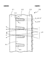
図3は、本発明の第三の実施形態のコントラスト向上シートS3を示している。このコントラスト向上シートS3は、観察者側から映像源側方向に順に、映像源側ベースシート31、レンズ部32、観察者側ベースシート33が貼り合わされて配置されており、映像源側ベースシート33の映像源側には連続プリズム形状のプリズムレンズ35が設けられている。レンズ部32は屈折率N1を有する物質により形成されている。上下方向に隣接するレンズ部32の間に挟まれた楔形部34は映像源側に先端を有し、楔形部34の内部には、レンズ部32の屈折率N1と略同一の屈折率を有する物質が充填されている。さらに、図において楔形部34の斜面および上底面は、屈折率N2を備え透明な物質により形成された層36(以下「透明屈折率層36」という。)により形成されている。
(Third embodiment)
FIG. 3 shows a contrast enhancing sheet S3 of the third embodiment of the present invention. The contrast improving sheet S3 is arranged by adhering an image source
レンズ部32の屈折率N1と、透明低屈折率層36の屈折率N2は、コントラスト向上シートS3の光学特性を得るために、上記の式(1)に示される所定の範囲に設定されている。また、透明屈折率層36とレンズ部32とが接する斜面が、出光面の法線V(当該コントラスト向上シートS3のレンズ部に対する垂直入射光に平行な線)となす角度は所定の角度θ3 に形成されている。θ3 は0°〜15°の範囲である。
The refractive index N1 of the
レンズ部32は通常電離放射線硬化性を有するエポキシアクリレートなどの材料にて構成されている。また、楔形部34は、カーボン、顔料又は所定の染料等にて所定濃度に着色されている。また、観察者側ベースシート31、及び映像源側ベースシート33は、レンズ部32と略同一の屈折率を有する材料にて構成されている。観察者側ベースシート31の外側面には、上記第一の実施形態にかかるコントラスト向上シートS1と同様に、観察者側にAR、AS、AGうち、少なくとも一の機能が備えられている。
The
映像源側ベースシート33の映像源側には連続プリズム形状の複数のプリズムレンズ35が紙面に垂直に設けられており、プリズムレンズ35は映像源からの拡散光を屈折させる。すなわち、プリズムレンズ35は垂直方向に光を制御する。プリズムレンズ35は、シート面を底面とする三角柱プリズムが配列されており、三角柱プリズムが映像源側ベースシート33の底面となす角度は、法線を上向きに持つ5°〜20°の緩斜面35aと法線を下向きに持つ50°〜90°の急斜面35bとを備えている。
A plurality of
かかる構成を有するコントラスト向上シートS3によっても、映像源側からの各入射光L31〜L33は第一の実施形態にかかるコントラスト向上シートS1における入射光L11〜L13と同様の光路をたどる。さらに、映像源側から斜面に所定以下の小さな角度をもって入射する光L34は、全反射されることなく楔形部34の内部に入光する。光L34は着色された楔形部34に吸収され、ゴースト発生が抑えられる。また、観察者側から楔形部34の底面に入射する外光L35は楔形部34の内部に入光し、光吸収効果を有する楔形部34に吸収される。さらに、観察者側から入射する外光のうち、プリズムレンズ35まで到達する外光L36は、プリズムレンズ35で反射されて楔形部34の内部に入光し、光吸収効果を有する楔形部34に吸収される。したがって観察者側からの視野による画像のコントラストが向上する。このように、コントラスト向上シートS3によっても、第一の実施形態におけるコントラスト向上シートS1と同様の効果、すなわち輝度、コントラストが高く、かつゴーストが抑えられ、断面方向に視野角を制御することが可能で、適正な視野角を有するコントラスト向上シートS3を得ることができる。
Also with the contrast enhancing sheet S3 having such a configuration, the incident lights L31 to L33 from the image source side follow the same optical paths as the incident lights L11 to L13 in the contrast enhancing sheet S1 according to the first embodiment. Further, the light L34 incident on the inclined surface from the image source side with a small angle of a predetermined angle or less enters the wedge-shaped
(第四の実施形態)
図4は、本発明の第四の実施形態にかかるコントラスト向上シートS4の断面を示している。このコントラスト向上シートS4は、観察者側から映像源側の方向に順に、映像源側ベースシート41、レンズ部42、観察者側ベースシート43が貼り合わされて配置されており、映像源側ベースシート43の映像源側には連続プリズム形状のプリズムレンズ45が設けられている。レンズ部42は屈折率N1を有する物質により形成されている。さらに、図面の上下方向に隣接する2つのレンズ部42にはさまれた断面形状台形の部分には、屈折率N2を備えた透明な物質(以下において「透明屈折率物質46」という。)中に光吸収粒子48が添加された材料で充填されている。以降の説明においては、この透明屈折率物質46が充填されている部分を「楔形部44」と呼ぶ。断面形状台形の楔形部44は、観察者側に下底面、映像源側に先端である上底面を備えている。
(Fourth embodiment)
FIG. 4 shows a cross section of a contrast enhancing sheet S4 according to the fourth embodiment of the present invention. The contrast improving sheet S4 is arranged by adhering the image source
本実施形態においては、レンズ部42の屈折率N1と、透明屈折率物質46の屈折率N2は、コントラスト向上シートS4の光学特性を得るために、上記の式(1)に示される所定の範囲に設定されている。また、楔形部44とレンズ部42とが接する斜面が、出光面の法線V(当該コントラスト向上シートS4のレンズ部に対する垂直入射光に平行な線)となす角度は所定の角度θ4 に形成されている。θ4 は0°〜15°の範囲である。
In the present embodiment, the refractive index N1 of the
レンズ部42は通常、電離放射線硬化性を有するエポキシアクリレートなどの材料にて構成されている。また、透明屈折率物質46として通常、電離放射線硬化性を有するウレタンアクリレートなどの材料が使用されている。光吸収粒子48は市販の着色樹脂微粒子が使用可能である。また、観察者側ベースシート41、及び映像源側ベースシート43は、レンズ部42と略同一の屈折率を有する材料にて構成されている。観察者側ベースシート43の観察者側には、本実施形態においても、上記第一の実施形態におけるコントラスト向上シートS1と同様に、観察者側にAR、AS、AGうち、少なくとも一の機能を備えている。
The
映像源側ベースシート43の映像源側には連続プリズム形状の複数のプリズムレンズ45が紙面に垂直に設けられており、プリズムレンズ45は映像源からの拡散光を屈折させる。すなわち、プリズムレンズ45は垂直方向に光を制御する。プリズムレンズ45は、シート面を底面とする三角柱プリズムが配列されており、三角柱プリズムが映像源側ベースシート43の底面となす角度は、法線を上向きに持つ5°〜20°の緩斜面45aと法線を下向きに持つ50°〜90°の急斜面45bとを備えている。
On the image source side of the image source side base sheet 43, a plurality of
次にコントラスト向上シートS4のレンズ部42内に入光した光の光路について、図4を参照しつつ簡単に説明する。なお、図4において、光L41〜L43、及びL44の光路は模式的に示されたものである。いま、図4において、映像源側からレンズ部42の中央部付近に入射した光L41は、そのままコントラスト向上シートS4の内部を直進して通過し、観察者に至る。映像源側からレンズ部42の端部に垂直に入射した光L42は、レンズ部42と透明屈折率物質46との屈折率差により斜面にて反射され、所定の角度をもって観察者側に出光される。映像源側からレンズ部42の端部付近に角度をもって入射した光L43は、斜面にて反射され、入射時とは反対方向にさらに大きな角度をもって観察者側に出光される。映像源側から斜面に所定以下の小さな角度をもって入射する光L44は、楔形部44の内部に入光する。光L44は楔形部44の光吸収粒子48に吸収され、ゴーストの発生が抑えられる。また、観察者側から楔形部44の底面に入射する外光L45は楔形部44の内部に入光し、光吸収効果を有する光吸収粒子48に吸収される。さらに、観察者側から入射する外光のうち、プリズムレンズ45まで到達する外光L46は、プリズムレンズ45で反射されて楔形部44の内部に入光し、光吸収粒子48に吸収される。このようにしてコントラスト向上シートS4によっても、第一の実施形態におけるコントラスト向上シートS1と同様の効果、すなわち輝度、コントラストが高く、かつゴーストが抑えられ、断面方向に視野角を制御することが可能で、適正な視野角を有するコントラスト向上シートS4を得ることができる。
Next, the optical path of the light entering the
(第五の実施形態)
図5は、本発明の第五の実施形態のコントラスト向上シートS5を示している。このコントラスト向上シートS5も、観察者側から映像源方向に順に、観察者側ベースシート51、レンズ部52、映像源側ベースシート53が貼り合わされて配置されており、映像源側ベースシート53の映像源側には連続プリズム形状のプリズムレンズ55が設けられている。レンズ部52は屈折率N1を有する物質により形成されている。上下方向に隣接するレンズ部52の間に挟まれた部分は、断面形状台形の楔形部54を形成し、映像源側に先端を有し、楔形部54の斜面および上底面は、屈折率N2を備え透明な物質により形成された層56(以下「透明屈折率層56」という。)により形成されている。さらに、楔形部54の内部には、N2より高い屈折率を有する物質中に光吸収粒子58が添加された材料が充填されている。
(Fifth embodiment)
FIG. 5 shows a contrast enhancing sheet S5 according to the fifth embodiment of the present invention. The contrast enhancing sheet S5 is also arranged by adhering the observer side base sheet 51, the
レンズ部52の屈折率N1と、透明屈折率層56の屈折率N2とは、コントラスト向上シートS5の光学特性を得るために、式(1)に示される所定の範囲に設定されている。また、透明低屈折率層56とレンズ部52とが接する斜辺が、出光面の法線V(当該コントラスト向上シートS5のレンズ部に対する垂直入射光に平行な線)となす角度は所定の角度θ5 に形成されている。θ5 は0°〜15°の範囲である。
The refractive index N1 of the
レンズ部52は通常、電離放射線硬化性を有するエポキシアクリレートなどの材料にて構成されている。光吸収粒子58は市販の着色樹脂微粒子が使用可能である。また、映像源側ベースシート51、及び観察者側ベースシート53は、レンズ部52と略同一の屈折率を有する材料にて形成されている。観察者側ベースシート53の観察者側には、本実施形態においても、上記第一実施形態にかかるコントラスト向上シートS1と同様に、観察者側にAR、AS、AGうち、少なくとも一の機能を備えている。
The
映像源側ベースシート53の映像源側には連続プリズム形状の複数のプリズムレンズ55が紙面に垂直に設けられており、プリズムレンズ55は映像源からの拡散光を屈折させる。すなわち、プリズムレンズ55は垂直方向に光を制御する。プリズムレンズ55は、シート面を底面とする三角柱プリズムが配列されており、三角柱プリズムが映像源側ベースシート53の底面となす角度は、法線を上向きに持つ5°〜20°の緩斜面55aと法線を下向きに持つ50°〜90°の急斜面55bとを備えている。
On the image source side of the image source side base sheet 53, a plurality of
次にコントラスト向上シートS5のレンズ部52内に入光した光の光路について、図5を参照しつつ簡単に説明する。なお、図5においても、光L51〜L53、及びL54の光路は模式的に示されたものである。図5において、映像源側からレンズ部52の中央部付近に入射した光L51は、そのままコントラスト向上シートS5の内部を直進して通過し、観察者に至る。映像源側からレンズ部52の端部付近に垂直に入射した光L52は、レンズ部52と透明低屈折率層54との屈折率差により斜面にて反射され、所定の角度をもって観察者側に出光される。映像源側からレンズ部52の端部付近に角度をもって入射した光L53は、斜面にて反射され、入射時とは反対方向にさらに大きな角度をもって、観察者側に出光される。さらに、映像源側から斜面に所定以上の大きな角度をもって入射する光L54は、楔形部54の内部に入光する。光L54は楔形部54の光吸収粒子58に吸収され、ゴーストの発生が抑えられる。また、観察者側から楔形部54の底面57に入射する外光L55は楔形部54の内部に入光し、光吸収効果を有する光吸収粒子58に吸収される。さらに、観察者側から入射する外光のうち、プリズムレンズ55まで到達する外光L56は、プリズムレンズ55で反射されて楔形部54の内部に入光し、光吸収粒子58に吸収される。このようにして、輝度、コントラストが高く、かつゴーストが抑えられ、断面方向に視野角を制御することが可能で、適正な視野角を有するコントラスト向上シートS5を得ることができる。
Next, the optical path of the light entering the
第四の実施形態及び第五の実施形態におけるコントラスト向上シートS4、S5における光吸収粒子48、58は、平均粒径が1μm以上で、楔形部が略台形の場合には、楔形部44、54の上底面の幅以下であることが好ましい。光吸収粒子48、58の大きさが1μm未満と小さすぎると、十分な光吸収効果を得ることができない。一方、光吸収粒子48、58の大きさが大きすぎ先端部である上底面の幅を超えると、製造時に、楔形部44、54の内部に充填しにくくなり好ましくない。
また、第四の実施形態及び第五の実施形態におけるコントラスト向上シートS4、S5における光吸収粒子48、58は、楔形部44、54の全体の体積に対して10〜50体積%であることが好ましい。かかる比率を維持することによって、十分な光吸収効果を保ちつつ、容易な製造条件を与えることができる。
The light-absorbing
Further, the
本発明においては、楔形部の断面形状が略等脚台形で映像源側に先端を有する場合について説明しているが、楔形部の断面形状が略二等辺三角形で映像源側に先端を有するの場合においても、良好なコントラスト向上シートが得られる。また、楔形部が観察者側に先端を有する場合であっても、本発明のコントラスト向上シートの発明の思想は適用し得るものである。 In the present invention, the case where the wedge-shaped portion has a substantially isosceles trapezoidal cross-section and has a tip on the image source side has been described. However, the wedge-shaped portion has a substantially isosceles triangular cross-section and has a tip on the image source side. Even in this case, a good contrast improving sheet can be obtained. Even if the wedge-shaped portion has a tip on the viewer side, the inventive concept of the contrast enhancing sheet of the present invention can be applied.
さらに、本発明においては、楔形部をなす断面形状が略台形もしくは略三角形であって、楔形部の2つの斜面部分が出光面の法線となす各々の角度が異なっていても適用可能である。次に、図6を用いて説明する。
図6は、楔形部64の斜面部分の形状が別な態様を示すコントラスト向上シートの断面図である。この楔形部64は断面形状が台形をなすが、楔形部64の2つの斜面部分が出光面の法線となす各々の角度が異なっており、図6においては、紙面の上側の角度θ61が下側の角度θ62より大きく、例えば、図6では、上側の角度θ61が10°、下側の角度θ62は0°の場合を例示している。図6に示すように、楔形部64の斜面部分の上側の角度が下側の角度より大きい状態にて、楔形部を水平方向に配列させた横ストライプで表示装置に用いることにより、映像源からの上方向の光に対して透過率が高く、観察者側の輝度をより向上させることができる。
Furthermore, the present invention is applicable even if the cross-sectional shape forming the wedge-shaped portion is a substantially trapezoidal shape or a substantially triangular shape, and the two inclined surfaces of the wedge-shaped portion are different from each other in the normal to the light exit surface. . Next, a description will be given with reference to FIG.
FIG. 6 is a cross-sectional view of a contrast enhancing sheet in which the shape of the slope portion of the wedge-shaped
図7は、本発明のコントラスト向上シートの構成の一例を示す図である。図7に示されるコントラスト向上シートS7は垂直断面形状が水平方向に一定な単位レンズ部72を備えている。観察者側にはベースシート71が、映像源側にはベースシート73が配置されており、ベースシート73の映像源側には三角柱プリズムレンズ75が水平方向に配列されている。図面では理解のためにこれら三者が離れて表されているが、実際にはこれらは貼り合わされている。
FIG. 7 is a diagram showing an example of the configuration of the contrast enhancing sheet of the present invention. The contrast enhancing sheet S7 shown in FIG. 7 includes a
図8は、本発明にかかる図7に示したコントラスト向上シートを備えた表示装置80の構成を示している。図8において、紙面手前左下方向が観察者側であり、紙面奥側右上方向を映像源側とする。本発明の表示装置80は、映像源側から順に、液晶ディスプレイパネル(LCD)81と、映像源側に三角柱プリズムレンズ75が設けられたベースシート73と、レンズ部が水平方向に配列されたコントラスト向上シート72と、さらに観察者側にAR、AS、AGうち、少なくとも一つの機能が備えられている機能性シート71とを備えている。図8においてはこれらが互いに離れて表されているが、これは図面の理解のためであり、実際にはこれらは互いに接するか、又は接着されている。
本発明のコントラスト向上シートは、OLED、PDP(プラズマディスプレイパネル)等、他のディスプレイにも適用することができる。
FIG. 8 shows a configuration of the
The contrast improving sheet of the present invention can be applied to other displays such as OLED and PDP (plasma display panel).
(実施例1)
図4に示すような、観察者側ベースシート、レンズ部、映像源側にプリズムレンズを設けた映像源側ベースシートより構成され、断面形状等脚台形の楔形部を有し、映像源側に幅の狭い先端部を持ち、さらに図示はされていないが、台形部の下底面にブラックストライプBSを設けたコントラスト向上シートを下記仕様にて作製した。BS率はコントラスト向上シートの楔形部下底面に形成されたブラックストライプBSの面積比率を示し、台形テーパー角度は台形の斜面部分が出光面の法線となす角度(θ)である。
BS率:25%
レンズ間ピッチ:0.1mm
レンズ部材料(樹脂)屈折率:1.56
楔形部材料屈折率:1.56
楔形部上底面幅:7μm
台形テーパー角度:5°
黒色光吸収粒子粒径:5μm
プリズムレンズ角度:上側緩斜面;10°、下側急斜面;60°
上記のシートは、特に上方からの外光に対して明室コントラストが向上し、さらに入射角度の大きい光は楔形部で吸収されるので、輝度はほとんど減少せず、またゴーストも抑えられたコントラスト向上シートが得られた。
Example 1
As shown in FIG. 4, it is composed of an observer-side base sheet, a lens unit, and an image source-side base sheet provided with a prism lens on the image source side. Although not shown, a contrast improving sheet having a black stripe BS provided on the lower bottom surface of the trapezoidal part was manufactured according to the following specifications. The BS ratio indicates the area ratio of the black stripe BS formed on the bottom bottom surface of the wedge-shaped portion of the contrast improving sheet, and the trapezoidal taper angle is an angle (θ) formed by the trapezoidal slope portion and the normal line of the light emitting surface.
BS rate: 25%
Lens pitch: 0.1 mm
Lens part material (resin) Refractive index: 1.56
Wedge material refractive index: 1.56
Wedge-shaped upper base width: 7 μm
Trapezoid taper angle: 5 °
Black light absorbing particle diameter: 5 μm
Prism lens angle: upper gentle slope; 10 °, lower steep slope; 60 °
The above-mentioned sheet improves the bright room contrast especially for the external light from above, and the light with a large incident angle is absorbed by the wedge-shaped part, so that the brightness is hardly reduced and the ghost is suppressed. An improved sheet was obtained.
(実施例2)
断面形状台形の楔形部を有し、図6に示すように、台形の上側斜面のテーパーを10°、下側斜面のテーパーを0°とし、それ以外の条件は実施例1と同じであるコントラスト向上シートを作製した。
このコントラスト向上シートもコントラストが高く、入射角度の大きい光は楔形部で吸収されるので、輝度はほとんど減少せず、ゴーストが抑えられたコントラスト向上シートが得られた。
(Example 2)
Contrast having the same trapezoidal wedge shape as shown in FIG. 6 except that the upper slope of the trapezoid has a taper of 10 ° and the lower slope has a taper of 0 °. An improvement sheet was produced.
This contrast enhancing sheet also has high contrast, and light having a large incident angle is absorbed by the wedge-shaped portion, so that the brightness is hardly reduced and a contrast enhancing sheet with suppressed ghost is obtained.
(実施例3)
プリズムレンズの上側緩斜面の角度を変えた以外は、実施例1と同じ条件で数種類のコントラスト向上シートを作製し、それらのシートを液晶表示装置の前面に順次設置し、視野角の好ましさとコントラストの良否を、目視による○×判定で比較した。その結果、および総合評価を表1に示す。
(Example 3)
Except for changing the angle of the upper gentle slope of the prism lens, several types of contrast enhancing sheets were produced under the same conditions as in Example 1, and these sheets were sequentially placed on the front surface of the liquid crystal display device. The quality of the contrast was compared by visual check. The results and overall evaluation are shown in Table 1.

表1に示す上側緩斜面の角度10°の場合は、実施例1と同じである。表1に示されるように、緩斜面角度が20°を超えると、視野角が小さくなって観察者に好ましくなくなり、一方、緩斜面角度が1°未満だと、コントラストが低下してしまう。したがって、プリズムレンズの好ましい上側緩斜面角度は、5°〜20°の範囲となり、この範囲において、コントラストが高く好ましい視野角を有するコントラスト向上シートが得られた。 When the angle of the upper gentle slope shown in Table 1 is 10 °, it is the same as the first embodiment. As shown in Table 1, when the gentle slope angle exceeds 20 °, the viewing angle becomes small, which is not preferable for the observer. On the other hand, when the gentle slope angle is less than 1 °, the contrast is lowered. Therefore, a preferable upper gentle slope angle of the prism lens is in a range of 5 ° to 20 °, and in this range, a contrast improving sheet having a high contrast and a preferable viewing angle is obtained.
(実施例4)
プリズムレンズの下側急斜面の角度を変えた以外は、実施例1と同じ条件で数種類のコントラスト向上シートを作製した。緩斜面の角度は実施例1と同じ10°である。作製した数種類のシートを液晶表示装置の前面に順次設置し、製造上の制約とコントラストの良否を、目視による○×判定で比較した。その結果、および総合評価を表2に示す。
Example 4
Several types of contrast improving sheets were produced under the same conditions as in Example 1 except that the angle of the lower steep slope of the prism lens was changed. The angle of the gentle slope is 10 ° as in Example 1. Several kinds of produced sheets were sequentially placed on the front surface of the liquid crystal display device, and the manufacturing restrictions and contrast quality were compared by visual check. The results and overall evaluation are shown in Table 2.
表2に示す下側急斜面の角度60°の場合は、実施例1と同じである。表2に示されるように、急斜面角度が90°を超えると、プリズムレンズの製造が困難となり、一方、急斜面角度が50°未満だと、コントラストが低下してしまう。したがって、プリズムレンズの好ましい下側急斜面角度は、50°〜90°の範囲となり、この範囲において、コントラスタが高く製造が容易なコントラスト向上シートが得られた。 When the angle of the lower steep slope shown in Table 2 is 60 °, it is the same as the first embodiment. As shown in Table 2, when the steep slope angle exceeds 90 °, it is difficult to manufacture the prism lens. On the other hand, when the steep slope angle is less than 50 °, the contrast is lowered. Therefore, a preferable lower steep slope angle of the prism lens is in a range of 50 ° to 90 °, and in this range, a contrast improving sheet having a high contrast and easy to manufacture is obtained.
以上、現時点において、もっとも、実践的であり、かつ、好ましいと思われる実施形態
に関連して本発明を説明したが、本発明は、本願明細書中に開示された実施形態に限定さ
れるものではなく、請求の範囲及び明細書全体から読み取れる発明の要旨あるいは思想に
反しない範囲で適宜変更可能である。
While the present invention has been described in connection with embodiments that are presently the most practical and preferred, the present invention is not limited to the embodiments disclosed herein. Instead, the present invention can be changed as appropriate without departing from the spirit or concept of the invention that can be read from the claims and the entire specification.
S1、S2、S3、S4、S5、S6、S7 コントラスト向上シート
11、21、31、41、51、61、71 観察者側ベースシート
12、22、32、42、52、62、72 レンズ部
13、23、33、43、53、63、73 映像源側ベースシート
14、24、34、44、54、64、74 楔形部
15、25、35、45、55、65、75 プリズムレンズ
15a、25a、35a、45a、55a プリズムレンズの緩斜面
15b、25b、35b、45b、55b プリズムレンズの急斜面
36、56 透明屈折率層
46 透明屈折率物質
48、58 光吸収粒子
80 表示装置
L11、L12、L13、L21、L22、L23、L31、L32、L33、L41、 L42、L43、L51、L52、L53、L6 光線
L14、L24、L34、L44、L54 光
L15、L25、L35、L45、L55、L16、L26、L36、L46、L56 外光
S9 プリズムレンズを設けていないコントラスト向上シート
91 観察者側ベースシート
92 レンズ部
93 映像源側ベースシート
94 楔形部
L95、L96、L97 外光
S1, S2, S3, S4, S5, S6, S7
Claims (12)
前記コントラスト向上シートは、断面形状が台形のレンズ部が所定の間隔で配列されるとともに、隣り合う前記レンズ部間の楔形部は、前記レンズ部と、同一又は異なる材料が充填され、前記楔形部は、映像源側もしくは観察者側に先端を有し、かつ、光吸収効果を有し、
前記コントラスト向上シートを構成するシートの最も映像源側であるシート面に、プリズムレンズが設けられ、
前記プリズムレンズは、前記シート面を底面とする三角柱プリズムが配列されており、前記三角柱プリズムが前記底面となす角度が、法線を上向きに持つ5°〜20°の緩斜面と法線を下向きに持つ50°〜90°の急斜面とを備える
ことを特徴とする表示装置。 A display device comprising: a video source that emits video light; and a contrast enhancement sheet that is disposed closer to the viewer than the video source,
In the contrast improving sheet, lens portions having a trapezoidal cross-sectional shape are arranged at a predetermined interval, and a wedge shape portion between adjacent lens portions is filled with the same or different material as the lens portion, and the wedge shape portion Has a tip on the image source side or the viewer side, and has a light absorption effect ,
A prism lens is provided on the sheet surface that is the most image source side of the sheet constituting the contrast enhancing sheet,
In the prism lens, a triangular prism having the sheet surface as a bottom surface is arranged, and an angle between the triangular prism and the bottom surface is a gentle slope of 5 ° to 20 ° having a normal line upward and a normal line downward. display device, characterized in that it comprises a steep 50 ° to 90 ° with the.
Nx−Ny≧−0.01
なる関係を有することを特徴とする請求項1〜4のいずれか1項に記載の表示装置。 Nx−Ny ≧ −0.01 between the refractive index Nx of the material constituting at least the slope portion of the wedge-shaped portion and the refractive index Ny of the material constituting the lens portion.
Display device according to any one of claims 1 to 4, characterized in that it has a following relationship.
Priority Applications (1)
| Application Number | Priority Date | Filing Date | Title |
|---|---|---|---|
| JP2004272242A JP4481125B2 (en) | 2004-09-17 | 2004-09-17 | Display device |
Applications Claiming Priority (1)
| Application Number | Priority Date | Filing Date | Title |
|---|---|---|---|
| JP2004272242A JP4481125B2 (en) | 2004-09-17 | 2004-09-17 | Display device |
Publications (3)
| Publication Number | Publication Date |
|---|---|
| JP2006085050A JP2006085050A (en) | 2006-03-30 |
| JP2006085050A5 JP2006085050A5 (en) | 2007-08-23 |
| JP4481125B2 true JP4481125B2 (en) | 2010-06-16 |
Family
ID=36163584
Family Applications (1)
| Application Number | Title | Priority Date | Filing Date |
|---|---|---|---|
| JP2004272242A Active JP4481125B2 (en) | 2004-09-17 | 2004-09-17 | Display device |
Country Status (1)
| Country | Link |
|---|---|
| JP (1) | JP4481125B2 (en) |
Families Citing this family (19)
| Publication number | Priority date | Publication date | Assignee | Title |
|---|---|---|---|---|
| WO2007084297A2 (en) | 2006-01-12 | 2007-07-26 | 3M Innovative Properties Company | Light-collimating film |
| JP5050407B2 (en) * | 2006-05-18 | 2012-10-17 | 株式会社日立製作所 | Front plate and display device using the same |
| JP5034430B2 (en) * | 2006-10-16 | 2012-09-26 | 大日本印刷株式会社 | Optical sheet |
| JP5007550B2 (en) * | 2006-10-16 | 2012-08-22 | 大日本印刷株式会社 | Optical sheet |
| CN104375224A (en) | 2007-10-16 | 2015-02-25 | 3M创新有限公司 | Higher transmission light control film |
| CN101903809B (en) | 2007-12-21 | 2012-02-29 | 3M创新有限公司 | Light control film |
| KR101184883B1 (en) | 2008-05-21 | 2012-09-21 | 주식회사 엘지화학 | Optical film for oled |
| JP2010232087A (en) * | 2009-03-27 | 2010-10-14 | Sony Corp | Optical film and light-emitting device |
| EP2443492A4 (en) | 2009-06-18 | 2018-01-10 | 3M Innovative Properties Company | Light control film |
| JP5240106B2 (en) * | 2009-07-06 | 2013-07-17 | 大日本印刷株式会社 | Optical filter and image display device |
| JP5909878B2 (en) * | 2010-05-31 | 2016-04-27 | 大日本印刷株式会社 | Manufacturing method of visibility improving sheet and visibility improving sheet |
| CN106842394A (en) | 2010-06-25 | 2017-06-13 | 安德鲁·理查德·帕克 | Optical effect structure |
| JP2012098667A (en) * | 2010-11-05 | 2012-05-24 | Dainippon Printing Co Ltd | Display panel and image display device using the same |
| JP2012098664A (en) * | 2010-11-05 | 2012-05-24 | Dainippon Printing Co Ltd | Display panel and image display device using the same |
| JP2014002927A (en) * | 2012-06-19 | 2014-01-09 | Dainippon Printing Co Ltd | Display device |
| JP2014002928A (en) * | 2012-06-19 | 2014-01-09 | Dainippon Printing Co Ltd | Display device |
| JP6736846B2 (en) * | 2014-07-30 | 2020-08-05 | 大日本印刷株式会社 | Optical sheet, surface light source device, image source unit, and display device |
| JP6710957B2 (en) * | 2015-12-17 | 2020-06-17 | 大日本印刷株式会社 | Image source unit and display device |
| JP6834153B2 (en) * | 2016-03-14 | 2021-02-24 | 大日本印刷株式会社 | Space floating image display device |
Citations (2)
| Publication number | Priority date | Publication date | Assignee | Title |
|---|---|---|---|---|
| JP2003066206A (en) * | 2001-08-27 | 2003-03-05 | Dainippon Printing Co Ltd | Enlarging member for two dimensional viewing angle, and display device |
| JP2004151592A (en) * | 2002-10-31 | 2004-05-27 | Dainippon Printing Co Ltd | Contrast improvement sheet and back projection type screen |
-
2004
- 2004-09-17 JP JP2004272242A patent/JP4481125B2/en active Active
Patent Citations (2)
| Publication number | Priority date | Publication date | Assignee | Title |
|---|---|---|---|---|
| JP2003066206A (en) * | 2001-08-27 | 2003-03-05 | Dainippon Printing Co Ltd | Enlarging member for two dimensional viewing angle, and display device |
| JP2004151592A (en) * | 2002-10-31 | 2004-05-27 | Dainippon Printing Co Ltd | Contrast improvement sheet and back projection type screen |
Also Published As
| Publication number | Publication date |
|---|---|
| JP2006085050A (en) | 2006-03-30 |
Similar Documents
| Publication | Publication Date | Title |
|---|---|---|
| JP4468121B2 (en) | Viewing angle control sheet and display device | |
| JP4481125B2 (en) | Display device | |
| JP5471821B2 (en) | Viewing angle control sheet | |
| JP4536626B2 (en) | Display device | |
| JP2005338270A (en) | Visibility angle control sheet | |
| US8262271B2 (en) | Display | |
| JP4766003B2 (en) | Display device | |
| JP4190253B2 (en) | Contrast enhancing sheet and rear projection screen | |
| KR100788525B1 (en) | Light diffusion sheet | |
| JP2004062084A (en) | Visibility enhancement sheet and display using same | |
| JP2010102308A (en) | Projection screen | |
| JP2009288799A (en) | Display device | |
| JP4502938B2 (en) | Display device | |
| JP2006184609A (en) | Viewing angle control sheet and image display apparatus using same | |
| JP2010122390A (en) | Light diffusion sheet and liquid crystal display device provided with the same | |
| JP4481149B2 (en) | Display device | |
| JP4853418B2 (en) | Optical sheet and display device including the optical sheet | |
| KR100837486B1 (en) | Viewing angle control sheet and display unit | |
| JP2009163245A (en) | Optical sheet and display device having the same | |
| TWI378314B (en) | Screen of a projecting device | |
| JP4299272B2 (en) | Diffusion plate for transmissive screen, transmissive screen and rear projection display | |
| CN112666640B (en) | Optical film layer and display device | |
| JP5208895B2 (en) | Display device | |
| JP2009122567A (en) | Screen and projection system | |
| KR100278205B1 (en) | Wide viewing angle device for non-luminescent display |
Legal Events
| Date | Code | Title | Description |
|---|---|---|---|
| A621 | Written request for application examination |
Free format text: JAPANESE INTERMEDIATE CODE: A621 Effective date: 20070629 |
|
| A521 | Written amendment |
Free format text: JAPANESE INTERMEDIATE CODE: A523 Effective date: 20070706 |
|
| A131 | Notification of reasons for refusal |
Free format text: JAPANESE INTERMEDIATE CODE: A131 Effective date: 20091222 |
|
| RD02 | Notification of acceptance of power of attorney |
Free format text: JAPANESE INTERMEDIATE CODE: A7422 Effective date: 20100129 |
|
| A521 | Written amendment |
Free format text: JAPANESE INTERMEDIATE CODE: A523 Effective date: 20100222 |
|
| TRDD | Decision of grant or rejection written | ||
| A01 | Written decision to grant a patent or to grant a registration (utility model) |
Free format text: JAPANESE INTERMEDIATE CODE: A01 Effective date: 20100316 |
|
| A01 | Written decision to grant a patent or to grant a registration (utility model) |
Free format text: JAPANESE INTERMEDIATE CODE: A01 |
|
| A61 | First payment of annual fees (during grant procedure) |
Free format text: JAPANESE INTERMEDIATE CODE: A61 Effective date: 20100317 |
|
| FPAY | Renewal fee payment (event date is renewal date of database) |
Free format text: PAYMENT UNTIL: 20130326 Year of fee payment: 3 |
|
| R150 | Certificate of patent or registration of utility model |
Ref document number: 4481125 Country of ref document: JP Free format text: JAPANESE INTERMEDIATE CODE: R150 Free format text: JAPANESE INTERMEDIATE CODE: R150 |
|
| FPAY | Renewal fee payment (event date is renewal date of database) |
Free format text: PAYMENT UNTIL: 20130326 Year of fee payment: 3 |
|
| FPAY | Renewal fee payment (event date is renewal date of database) |
Free format text: PAYMENT UNTIL: 20140326 Year of fee payment: 4 |