JP4467922B2 - Inkjet recording apparatus and inkjet recording head - Google Patents
Inkjet recording apparatus and inkjet recording head Download PDFInfo
- Publication number
- JP4467922B2 JP4467922B2 JP2003280338A JP2003280338A JP4467922B2 JP 4467922 B2 JP4467922 B2 JP 4467922B2 JP 2003280338 A JP2003280338 A JP 2003280338A JP 2003280338 A JP2003280338 A JP 2003280338A JP 4467922 B2 JP4467922 B2 JP 4467922B2
- Authority
- JP
- Japan
- Prior art keywords
- ink
- color
- nozzle
- recording
- main scanning
- Prior art date
- Legal status (The legal status is an assumption and is not a legal conclusion. Google has not performed a legal analysis and makes no representation as to the accuracy of the status listed.)
- Expired - Fee Related
Links
Images


Classifications
-
- B—PERFORMING OPERATIONS; TRANSPORTING
- B41—PRINTING; LINING MACHINES; TYPEWRITERS; STAMPS
- B41J—TYPEWRITERS; SELECTIVE PRINTING MECHANISMS, i.e. MECHANISMS PRINTING OTHERWISE THAN FROM A FORME; CORRECTION OF TYPOGRAPHICAL ERRORS
- B41J19/00—Character- or line-spacing mechanisms
- B41J19/14—Character- or line-spacing mechanisms with means for effecting line or character spacing in either direction
- B41J19/142—Character- or line-spacing mechanisms with means for effecting line or character spacing in either direction with a reciprocating print head printing in both directions across the paper width
- B41J19/147—Colour shift prevention
Landscapes
- Ink Jet (AREA)
Description
本発明は、複数色のインクを用いてカラー記録を行うインクジェット記録装置および該インクジェット記録装置に用いられるインクジェット記録ヘッドに関し、詳しくは、所定方向に延びる各色ノズル列が当該所定方向と直交する主走査方向に沿ってそれぞれ配列されて成る記録ヘッドを主走査させて記録を行うインクジェット記録装置及び該インクジェット記録装置に用いられるインクジェット記録ヘッドに関する。 The present invention relates to an ink jet recording apparatus that performs color recording using a plurality of colors of ink and an ink jet recording head used in the ink jet recording apparatus, and more specifically, main scanning in which each color nozzle row extending in a predetermined direction is orthogonal to the predetermined direction. The present invention relates to an ink jet recording apparatus that performs recording by main-scanning recording heads that are arranged along a direction, and an ink jet recording head used in the ink jet recording apparatus.
インクジェット記録装置は、比較的小型で低騒音であり、かつ安価にカラー記録を行うことができるなどの理由により、急速に普及している。さらに近年においては、インクジェット記録装置の高画質化・高速化が顕著であり、写真調の画質の画像をA4サイズで1分程度の速度で出力することが可能となってきている。これは記録ヘッド、インク、記録媒体の技術改良もさることながら、記録装置本体のメカ制御等によるところも大きい。 Inkjet recording apparatuses are rapidly spreading due to their relatively small size, low noise, and ability to perform color recording at low cost. In recent years, the improvement in image quality and speed of ink jet recording apparatuses has been remarkable, and it has become possible to output photographic image quality images at an A4 size at a speed of about one minute. This is largely due to mechanical control of the recording apparatus main body as well as technical improvements of the recording head, ink, and recording medium.
近年のインクジェット記録装置では、記録ヘッドを記録媒体上で主走査方向に移動させ(以下これを「主走査」ともいう)、この走査中にインクを吐出して行う記録動作と、前記主走査方向に対し垂直方向に記録媒体を一定量だけ搬送する(以下これを「副走査」ともいう)紙送り動作とを交互に繰り返すことにより、記録媒体全体に記録を行う、シリアルタイプのものが一般的である。このようなシリアルタイプのものでは、記録ヘッドの走査制御によっても、記録に要する時間は大きく変わってくる。 In a recent ink jet recording apparatus, a recording operation is performed by moving a recording head on a recording medium in the main scanning direction (hereinafter also referred to as “main scanning”), and ejecting ink during the scanning, and the main scanning direction. In contrast, a serial type is generally used for recording on the entire recording medium by alternately repeating a paper feeding operation (hereinafter also referred to as “sub-scanning”) that conveys the recording medium in a vertical direction by a certain amount. It is. In such a serial type, the time required for recording varies greatly depending on the scanning control of the recording head.
シリアルタイプのカラー記録装置における記録ヘッドの構成は、大きく分けて2つのタイプがある。 The configuration of the recording head in the serial type color recording apparatus is roughly divided into two types.
一つ目のタイプとしては、図11(a)及び(b)に示すように、インクを吐出する多数のノズルが副走査方向に直線上に配置された記録ヘッド(縦並びヘッド)があげられる。図11(a)は、イエロー、マゼンタ、シアン、ブラックのインクを吐出させるための各色ノズル列が互いにオーバーラップしないように紙送り方向に1列に配置されたものである。また、図11(b)は、ブラックインクを吐出するブラック用ノズル列とカラーインクを吐出するカラー用ノズル列とが別個に構成されたものである。 As the first type, as shown in FIGS. 11A and 11B, there is a recording head (vertically arranged head) in which a large number of nozzles for ejecting ink are arranged in a straight line in the sub-scanning direction. . In FIG. 11A, the color nozzle rows for ejecting yellow, magenta, cyan, and black inks are arranged in one row in the paper feed direction so as not to overlap each other. In FIG. 11B, a black nozzle row for ejecting black ink and a color nozzle row for ejecting color ink are separately configured.
例えば、図11(b)に示す構成でカラー記録を行う場合、記録データに従い各色のインクが吐出されるが、1回の主走査では、これら各色インクドットを記録媒体上の異なる位置に形成するだけである。そして、二次色を形成するためには記録媒体の同一領域に他の色のドットも重ねて打ち込まなければならないので紙送り量はノズル列分、すなわち図中hで示す長さだけとなる。したがって、記録媒体の同一領域を記録ヘッドは約三回走査することになる。また、記録ヘッドの走査方向に関わらず、記録媒体の同一領域は常にシアン、マゼンタ、イエローの順でノズル列が走査するので、ブルー、レッド、グリーンのいわゆる二次色を形成する場合、記録ヘッドの走査方向に関わらず色の重ねの順序は一定となる。例えば、ブルーの画像を形成する場合は、まずシアンを印字した後にその上にマゼンタが重ねて印字されることになる。従って、同図の記録ヘッドを用いれば、記録ヘッドの往走査と復走査を交互に行って画像印刷を行う、いわゆる双方向印刷記録を行っても色むらを生じない。 For example, when color recording is performed with the configuration shown in FIG. 11B, ink of each color is ejected according to the recording data, but each color ink dot is formed at a different position on the recording medium in one main scan. Only. In order to form a secondary color, dots of other colors must be overlapped in the same area of the recording medium, so that the paper feed amount is only the length indicated by h in the figure, that is, h. Therefore, the recording head scans the same area of the recording medium about three times. In addition, since the nozzle row always scans cyan, magenta, and yellow in the same area of the recording medium regardless of the scanning direction of the recording head, when forming a so-called secondary color of blue, red, and green, the recording head Regardless of the scanning direction, the order of color superposition is constant. For example, when forming a blue image, first, cyan is printed, and then magenta is overlaid thereon. Therefore, if the recording head shown in the figure is used, color unevenness does not occur even when performing so-called bidirectional printing and recording, in which image printing is performed by alternately performing forward scanning and backward scanning of the recording head.
しかしながら、同図のヘッド構成の場合、高速化のために各色のノズル数を多くすればその分記録ヘッドの長さが長くなり、ヘッドや装置全体が大型化してしまう。あるいは記録部における記録媒体の抑え方法が複雑化する傾向にあり、記録ヘッドや装置のコストアップを招くといった問題が生じる。 However, in the case of the head configuration shown in the figure, if the number of nozzles of each color is increased for speeding up, the length of the recording head becomes longer and the size of the head and the entire apparatus is increased. Alternatively, the method of suppressing the recording medium in the recording unit tends to be complicated, and there arises a problem that the cost of the recording head and apparatus is increased.
二つ目のタイプとしては、例えば図12に示すように、ブラックインク、シアンインク、マゼンタインク、イエローインクを吐出するインク吐出部を主走査方向に平行に並べたヘッド(横並びヘッド)があげられる。この形態の記録ヘッドを用いる場合、1回の走査で記録媒体の同一領域に全ての色のインクが画像データに応じて吐出される。 As the second type, for example, as shown in FIG. 12, there is a head (side-by-side head) in which ink discharge portions for discharging black ink, cyan ink, magenta ink, and yellow ink are arranged in parallel in the main scanning direction. . When the recording head of this form is used, ink of all colors is ejected according to the image data in the same area of the recording medium in one scan.
記録の高速化のために記録ヘッドからのインク吐出を往走査(図中矢印A方向)時だけでなく、復走査(図中矢印B方向)時にも行う形態にすると、例えばブルー、レッド、グリーンのいわゆる二次色を形成する場合には、色の重ねの順序が記録ヘッドの往走査(図中矢印A方向)と復走査(図中矢印B方向)とで異なってしまう。その結果、各走査で色味が異なり、色むらとなって画像品位を大きく低下させてしまう。特に、ベタ印字などの高階調の画像では、この色むらが顕著となる。 In order to increase the recording speed, ink ejection from the recording head is performed not only during forward scanning (in the direction of arrow A in the figure) but also during backward scanning (in the direction of arrow B in the figure). When the so-called secondary color is formed, the order of color overlap differs between the forward scan (in the direction of arrow A in the figure) and the reverse scan (in the direction of arrow B in the figure). As a result, the color is different for each scan, resulting in uneven color and greatly reducing the image quality. In particular, this uneven color becomes noticeable in a high gradation image such as solid printing.
一方、画像の高画質化を目的とした記録方法として、マルチパス記録方法が存在する。これは、同一箇所を2回以上の走査で記録することによって、ヘッドが固有に持つノズル毎のばらつき等を緩和させるものである。この場合、1度に搬送される記録媒体の移動距離は、ヘッドの長さの半分以下である。したがって、マルチパス記録方法はこれを用いない場合に比べて走査回数が多くなるので、一般的に記録に要する時間は多くなる。そして、この記録時間を減らすためには、マルチパス記録方法で画像を形成する際においても、往復記録を用いることが有効である。その一方で、往復記録での色の重ね順序の違いによる色むらは、たとえマルチパス印刷方法を用いても完全に解消されることはない。マルチパス記録のパス数を増やしていくことで、色むらをほとんど目立たないようにすることも可能であるが、その分記録に要する時間は多くなる。したがって、記録に要する時間を減らすために行っている往復記録の意味がなくなってしまうこととなり、好ましくない。 On the other hand, there is a multi-pass recording method as a recording method aiming at high image quality. This is to reduce variations and the like for each nozzle inherent in the head by recording the same portion by scanning twice or more. In this case, the moving distance of the recording medium conveyed at one time is less than half the length of the head. Therefore, since the multipass printing method requires a larger number of scans than when this method is not used, the time required for printing generally increases. In order to reduce the recording time, it is effective to use reciprocal recording even when an image is formed by the multipass recording method. On the other hand, the color unevenness due to the difference in the color superposition order in the reciprocal recording is not completely eliminated even if the multi-pass printing method is used. By increasing the number of passes in multi-pass recording, it is possible to make color unevenness almost inconspicuous, but the time required for recording increases accordingly. Therefore, the meaning of the reciprocal recording performed to reduce the time required for recording is lost, which is not preferable.
また、図13に示すように、より高画質な画像を形成するために、ブラックインク、シアンインク、マゼンタインク、イエローインクの4色の他に淡シアン、淡マゼンタインクを加えた6色の記録ヘッドを並行に並べたものもある。この6色ヘッドを用いる場合も、図12の4色の記録ヘッドと同様に、往復記録時に色の重ね順序が異なることによる色むらが発生するという問題がある。 Further, as shown in FIG. 13, in order to form a higher quality image, the recording of six colors in which light cyan and light magenta inks are added in addition to the four colors of black ink, cyan ink, magenta ink, and yellow ink. Some heads are arranged in parallel. Even when this 6-color head is used, there is a problem that color unevenness occurs due to the difference in the order of color overlap during reciprocal recording, as in the case of the 4-color recording head shown in FIG.
以上説明したように、カラー記録を行うインクジェット記録装置に適した記録ヘッドの構成としては、インク色別のノズル列を一列に配列した構成(縦並びヘッド)と、平行に並べた構成(横並びヘッド)の2種類がある。高速記録に適しているのは、平行に並べた構成であるが、この構成では往復記録時に色の重ね順序が異なることで色むらが発生するという問題がある。 As described above, the configuration of a recording head suitable for an ink jet recording apparatus that performs color recording includes a configuration in which nozzle rows for each ink color are arranged in a row (vertical arrangement head), and a configuration in which the nozzle rows are arranged in parallel (horizontal arrangement head). There are two types. A configuration arranged in parallel is suitable for high-speed recording. However, this configuration has a problem that color unevenness occurs due to a difference in the color superposition order during reciprocal recording.
この問題を解決するために、カラーインクのノズル列を主走査方向において対称となるように配列した記録ヘッドが、特許文献1に記載されている。これは、往走査と復走査で吐出するノズル列を変えることにより、常にインクの打ち込み順序が同じになるようにしたものである。このような構成を採用することで、インクの打ち込み順序の違いによって発生する色むらを解消することができる。 In order to solve this problem, Patent Document 1 discloses a recording head in which color ink nozzle arrays are arranged symmetrically in the main scanning direction. In this method, the ink ejection order is always the same by changing the nozzle rows ejected in the forward scan and the backward scan. By adopting such a configuration, it is possible to eliminate color unevenness that occurs due to a difference in the ink ejection order.
しかしながら、上述の対称にノズル列を配列した記録ヘッドを用いたインクジェット記録装置においても、次のような問題がある。 However, the ink jet recording apparatus using the recording head in which the nozzle rows are arranged symmetrically has the following problems.
すなわち、この構成では、同じ色で複数のノズル列を持つ必要があり、ヘッドの大型化を招くことになる。さらに、電気系統やメカ系統においても、従来のものに比べ、余分に配線が必要となり、コストアップを招くことになる。さらに、高画質化を求めるべく、淡シアン、淡マゼンタのインクも加えた6色インクで上述の構成をとると、ノズル列として12個(6色×2)も必要となる。その結果、ヘッドおよび装置の巨大化を招く他、インクの流路構成が非常に複雑となり、更には吸引回復処理を行った際に十分に吸引ができない可能性が高くなり、信頼性の面でも問題がある。 That is, in this configuration, it is necessary to have a plurality of nozzle rows with the same color, leading to an increase in the size of the head. Furthermore, the electrical system and the mechanical system also require extra wiring as compared with the conventional system, resulting in an increase in cost. Further, in order to obtain a high image quality, if the above-described configuration is used with six color inks including light cyan and light magenta inks, 12 nozzle rows (6 colors × 2) are required. As a result, the size of the head and the device is increased, the ink flow path configuration becomes very complicated, and there is a high possibility that the ink cannot be sufficiently sucked when the suction recovery process is performed. There's a problem.
本発明は、上記従来の問題に鑑みてなされたものであり、記録ヘッドおよびインクジェット記録装置の大型化ならびにコストアップを極力招くことなく、往復記録時に発生するインクの重ね順序の違いによる色むらの発生を極力抑えることが可能なインクジェット記録装置、記録方法および記録ヘッドを提供することを目的とする。 The present invention has been made in view of the above-described conventional problems, and causes uneven color due to the difference in the ink stacking order that occurs during reciprocal recording without causing an increase in the size and cost of the recording head and the ink jet recording apparatus as much as possible. An object of the present invention is to provide an ink jet recording apparatus, a recording method, and a recording head capable of suppressing generation as much as possible.
上記目的を達成するための本発明は、ブラックのインクとカラーのインクを含む4色以上のインクに各々対応した複数のノズル列が主走査方向に沿って配置された記録部を前記主走査方向に往復走査させながら前記記録部より記録媒体に対してインクを吐出して双方向記録を行うインクジェット記録装置であって、前記カラーのインクの中で色相角の差が最も大きい組合せである2色のインクに各々対応した2つのノズル列が前記記録部の主走査方向における両端部に配置されることを特徴とする。 The present invention for achieving the above object, the main scanning direction a recording unit in which a plurality of nozzle arrays respectively corresponding to four or more colors of ink is disposed along the main scanning direction including the black ink and color ink An ink jet recording apparatus that performs bidirectional recording by ejecting ink from the recording unit to the recording medium while reciprocally scanning the ink , and the two colors having the largest difference in hue angle among the color inks two nozzle columns respectively corresponding to the ink and being disposed at both ends in the main scanning direction of the recording portion.
また、本発明は、ブラックのインクとカラーのインクを含む複数色のインクに各々対応した複数のノズル列が主走査方向に沿って配置された記録部を前記主走査方向へ往復走査させながら前記記録部から記録媒体に向けてインクを吐出して双方向記録を行うインクジェット記録装置であって、前記カラーのインクの中で色相角の差が最も大きい組合せである2色のインクに各々対応した2つのノズル列の間に、当該2色のインク以外の少なくとも2色のインクに各々対応した少なくとも2つのノズル列が配置されることを特徴とする。 Further, the present invention, the while each corresponding recording unit in which a plurality of nozzle arrays are arranged along the main scanning direction is reciprocally scanned to the main scanning direction into a plurality of color inks including a black ink and color ink an inkjet recording apparatus for performing bidirectional recording by discharging ink toward the recording medium from the recording unit and respectively corresponding to the two color inks difference hue angle is the largest combination in the ink of the color between two nozzle arrays, wherein at least two nozzle rows were each corresponding to at least two color inks other than the ink of the two colors are placed.
また、本発明は、ブラックインクと複数色のカラーインクに各々対応した複数のノズル列が主走査方向に沿って配置された記録部を前記主走査方向に往復走査させながら前記記録部より記録媒体に対してインクを吐出して双方向記録を行うインクジェット記録装置であって、前記複数色のカラーインクの中で色相角の差が最も大きい組合せである第1の色のカラーインクと第2の色のカラーインクに各々対応した2つのノズル列が前記記録部の主走査方向における両端部に配置され、且つ前記第1の色のカラーインクのノズル列と前記第2の色のカラーインクのノズル列との間に、前記ブラックインクのノズル列が挟まれて配置されることを特徴とする。 Further, the present invention includes a black ink and a plurality of colors plurality of nozzle arrays recording medium from the recording unit while the recording unit arranged along the main scanning direction is reciprocally scanned in the main scanning direction respectively corresponding to the color inks An ink jet recording apparatus that performs bidirectional recording by discharging ink to the first color ink and the second color ink that are the combination having the largest difference in hue angle among the color inks of the plurality of colors each corresponding two nozzle arrays are arranged at both ends in the main scanning direction of the recording portion in the color color ink, and the first color the color ink nozzle row and the second color color ink of the between the nozzle rows, nozzle row of the black ink is arranged being interposed, characterized in Rukoto.
また、本発明は、ブラックインク用ノズル列および3色以上のカラーインクに各々対応した3つ以上のカラーインク用ノズル列が主走査方向に沿って配置された記録部を前記主走査方向に往復走査させながら前記記録部より記録媒体に対してインクを吐出して双方向記録を行うインクジェット記録装置であって、前記3色以上のカラーインクの中で色相角の差が最も大きい組合せである第1の色のインクと第2の色のインクに各々対応した2つのカラーインク用ノズル列が、前記3つ以上のカラーインク用ノズル列のなかで最も離れるように配置されることを特徴とする。 The present invention also reciprocates recording unit in which three or more color ink nozzle rows respectively corresponding to the nozzle rows and three or more colors of the color ink for the black ink are arranged along the main scanning direction in the main scanning direction An inkjet recording apparatus that performs bidirectional recording by ejecting ink from a recording unit to a recording medium while scanning , and is a combination that has the largest difference in hue angle among the three or more color inks. two color ink nozzle rows respectively corresponding to the first color ink and the ink of the second color, and characterized in that it is placed as farthest among the three or more color ink nozzle array To do.
また、本発明は、ブラックのインクとカラーのインクを含む4色以上のインクに各々対応した複数のノズル列が主走査方向に沿って配置され、前記主走査方向への往復走査中に記録媒体にインクを吐出して双方向記録を行うためのインクジェット記録ヘッドであって、前記カラーのインクの中で色相角の差が最も大きい組合せである2色のインクに各々対応した2つのノズル列が、前記主走査方向における両端部に配置されることを特徴とする。 Further, the present invention includes a plurality of nozzle rows that respectively correspond to four or more colors of ink including black ink and color ink are arranged along the main scanning direction, the recording medium during reciprocal scanning in the main scanning direction an inkjet recording head for performing bidirectional recording by ejecting ink, the two nozzle arrays respectively corresponding to the two color inks difference hue angle is the largest combination in the ink of the color Are arranged at both ends in the main scanning direction.
また、本発明は、ブラックのインクとカラーのインクを含む複数色のインクに各々対応した複数のノズル列が主走査方向に沿って配置され、前記主走査方向への往復走査中に記録媒体にインクを吐出して双方向記録を行うためのインクジェット記録ヘッドであって、
前記カラーのインクの中で色相角の差が最も大きい組合せである2色のインクに各々対応した2つのノズル列の間に、当該色相角の差が最も大きい組合せの2色以外の少なくとも2色のインクに各々対応した2つのノズル列が配置されることを特徴とする。
According to the present invention, a plurality of nozzle rows respectively corresponding to a plurality of color inks including black ink and color ink are arranged along the main scanning direction, and the recording medium is reciprocated during the reciprocating scanning in the main scanning direction. An ink jet recording head for performing bidirectional recording by discharging ink ,
Between two nozzle arrays respectively corresponding to the two color inks difference hue angle is the largest combination in the ink of the color, at least two colors other than the two colors of the difference between the hue angle is the largest combined two nozzle columns respectively corresponding to the ink, characterized in that it is placed.
また、本発明は、ブラックインクと複数色のカラーインクに各々対応した複数のノズル列が主走査方向に沿って配置され、前記主走査方向への往復走査中に記録媒体にインクを吐出して双方向記録を行うためのインクジェット記録ヘッドであって、前記複数色のカラーインクの中で色相角の差が最も大きい組合せである2色のインクに各々対応した2つのノズル列が、前記主走査方向における両端部に配置され、且つ前記色相角の差が最も大きい組合せである2色のインクに各々対応した2つのノズル列の間に、前記ブラックインクのノズル列が挟まれて配置されることを特徴とする。 Further, the present invention includes a plurality of nozzle rows respectively corresponding to the black ink and a plurality of color inks are arranged along the main scanning direction by ejecting ink onto a recording medium during reciprocal scanning in the main scanning direction an inkjet recording head for performing bidirectional recording, two nozzle arrays respectively corresponding to the two color inks difference is greatest combination of hue angles among the plurality of color inks is, the main scanning arranged at both ends in the direction, are arranged and the between each corresponding two nozzle rows in two color inks difference is greatest combination of hue angles, sandwiched nozzle arrays of said black ink It is characterized by that.
また、本発明は、ブラックインクおよび3色以上のカラーインクに各々対応した複数のノズル列が主走査方向に沿って配置され、前記主走査方向への往復走査中に記録媒体にインクを吐出して双方向記録を行うためのインクジェット記録ヘッドであって、前記3色以上のカラーインクの中で色相角の差が最も大きい組合せである2色のインクに各々対応した2つのノズル列が、前記3色以上のカラーインクのノズル列のなかで最も離れるように配置されることを特徴とする。 Further, according to the present invention, a plurality of nozzle arrays respectively corresponding to black ink and three or more color inks are arranged along the main scanning direction, and the ink is ejected onto the recording medium during the reciprocating scanning in the main scanning direction. And two nozzle rows respectively corresponding to two color inks that are the combination having the largest difference in hue angle among the three or more color inks. characterized in that it is placed as farthest among the nozzle array of three or more colors of the color inks.
なお、本明細書において、「ノズル列」とは、インクを吐出するための複数のノズルが所定方向に配列されてなるものである。 In the present specification, the “nozzle row” is formed by arranging a plurality of nozzles for ejecting ink in a predetermined direction.
また、本明細書において、「記録部(あるいはインク吐出部)」とは、各インク色に対応した各色ノズル列を含む構成である。そして、これら各色ノズル列は、同じ記録ヘッドに一体的に設けられる形態であってもよいし、任意の数の異なる記録ヘッドに設けられる形態であってもよい。ここで、各色ノズル列が異なる記録ヘッドに設けられる形態とは、各色ノズル列の夫々が別の記録ヘッドに設けられる構成に限られず、各色ノズル列のうち少なくとも1つのノズル列が別の記録ヘッドに設けられる構成も含むものである。 Further, in this specification, the “recording unit (or ink ejection unit)” is a configuration including each color nozzle row corresponding to each ink color. Each of these color nozzle rows may be provided integrally with the same recording head, or may be provided with any number of different recording heads. Here, the form in which each color nozzle row is provided in different print heads is not limited to a configuration in which each color nozzle row is provided in a separate print head, and at least one nozzle row in each color nozzle row is a separate print head. The structure provided in is also included.
また、記録部(あるいはインク吐出部)に含まれる各色ノズル列が同じ記録ヘッドに一体的に設けられる形態の場合、これら各色ノズル列は1つのチップに形成される構成でもよいし、複数の異なるチップに形成される構成であってもよい。例えば、シアン(C)・マゼンタ(M)・イエロー(Y)・ブラック(K)・淡シアン(LC)・淡マゼンタ(LC)に対応する6色のノズル列が存在する場合、これら6色のノズル列が1つのチップに設けられる形態であってもよい。また、これら6色のノズル列の夫々が独立的に異なるチップに設けられる形態であってもよい。この場合、1つのチップにつき1色のノズル列が設けられるため、計6個のチップとなる。更には、これら6色のノズル列のうち、特定色(例えば、K)を一方のチップに設け、特定色以外の色(例えば、C・M・Y・LC・LM)を他方のチップに設ける形態であってもよい。また6色を任意の2色づつ(例えば、CとLC,KとY、LMとM)に組分けし計3つのチップに分割して設ける形態であってもよい。因みに、記録部(あるいはインク吐出部)に含まれる各色ノズル列が異なる記録ヘッドに設けられる形態の場合、当然、各色ノズル列のうち、少なくとも1つのノズル列が別チップに形成されることになるのはいうまでもない。 In the case where the color nozzle arrays included in the recording unit (or ink discharge unit) are integrally provided in the same recording head, the color nozzle arrays may be formed on one chip, or a plurality of different types. The structure formed in a chip | tip may be sufficient. For example, when there are six nozzle rows corresponding to cyan (C), magenta (M), yellow (Y), black (K), light cyan (LC), and light magenta (LC), these six colors The nozzle array may be provided in one chip. In addition, each of these six color nozzle rows may be independently provided on different chips. In this case, since one color nozzle row is provided for each chip, there are a total of six chips. Further, among these six color nozzle arrays, a specific color (for example, K) is provided on one chip, and a color other than the specific color (for example, C, M, Y, LC, and LM) is provided on the other chip. Form may be sufficient. Alternatively, the six colors may be divided into two arbitrary colors (for example, C and LC, K and Y, LM and M) and divided into a total of three chips. Incidentally, in the case where each color nozzle array included in the recording unit (or ink ejection unit) is provided in a different recording head, of course, at least one nozzle column among the color nozzle columns is formed in a separate chip. Needless to say.
本明細書において「色味差(色差)」とは、国際規格であるCIE1976L*a*b*色空間(以下、単にCIELab空間という)における色差であるΔEのことである。 In the present specification, “color difference (color difference)” refers to ΔE that is a color difference in an international standard, CIE1976L * a * b * color space (hereinafter simply referred to as CIELab space).
また、本明細書において「色相差」とは、CIELab色空間のa*b*平面上における2つ色それぞれに対応した色相角の差のことである。つまり、2色の色相角をそれぞれH1、H2とすると、この2色の色相角の差である|H1−H2|が色相差ΔHに相当し、ΔH=|H1−H2|である。 Further, in this specification, the “hue difference” is a difference in hue angle corresponding to each of two colors on the a * b * plane of the CIELab color space. That is, assuming that the hue angles of the two colors are H1 and H2, respectively, | H1-H2 |, which is the difference between the hue angles of the two colors, corresponds to the hue difference ΔH, and ΔH = | H1-H2 |.
ここで、色相角Hとは、a*b*平面上の角度のことであり、H=tan-1 (b*/a*)で求められる。つまり、一方の色の測色値(a*b*)が(a1 *b1 *)であり、他方の色の測色値(a*b*)が(a2 *b2 *)である場合、一方の色の色相角H1はtan-1 (b1 */a1 *)となり、他方の色の色相角H2はtan-1 (b2 */a2 *)となる。従って、2色(一方の色と他方の色)の色相差は、ΔH=| tan-1 (b1 */a1 *)−tan-1 (b2 */a2 *)|で求められる。 Here, the hue angle H is an angle on the a * b * plane, and is obtained by H = tan −1 (b * / a * ). That is, one color colorimetric values (a * b *) is (a 1 * b 1 *) is the other color colorimetric values (a * b *) is (a 2 * b 2 *) In some cases, the hue angle H1 of one color is tan -1 (b 1 * / a 1 * ), and the hue angle H2 of the other color is tan -1 (b 2 * / a 2 * ). Accordingly, the hue difference between the two colors (one color and the other color) is obtained by ΔH = | tan −1 (b 1 * / a 1 * ) − tan −1 (b 2 * / a 2 * ) | .
以上の構成によれば、色相差のもっとも大きい2色のノズル列(例えば、マゼンタ用ノズル列とシアン用ノズル列)の間に、少なくとも2色の他のノズル列(例えば、淡マゼンタ用ノズル列と淡シアン用ノズル列、あるいはブラック用ノズル列およびイエロー用ノズル列など)をはさみ込むように配列した構成の記録手段(あるいはインク吐出部)を採用しているため、色相差のもっとも大きい2色により二次色を形成する場合、先に吐出された一方のインク(例えば、シアン)が着弾してから他方のインク(例えば、マゼンタ)が着弾するまでの間に十分な時間が確保される。従って、色相差の最も大きい2色のノズル列が近接する形態(例えば、隣接する形態、あるいは両端に位置しない形態)に比べ、色むらの軽減効果が大きい。すなわち、往復記録時に発生するインクの重ね順序の違いによる「色むら」を十分抑制することができる。 According to the above configuration, at least two other color nozzle rows (for example, light magenta nozzle row) between the two color nozzle rows (for example, magenta nozzle row and cyan nozzle row) having the largest hue difference. And the light cyan nozzle row, or the black nozzle row and the yellow nozzle row, etc.) are used, so that the two colors with the largest hue difference are used. When a secondary color is formed by this, a sufficient time is ensured between the landing of one of the previously ejected inks (for example, cyan) and the landing of the other ink (for example, magenta). Therefore, the effect of reducing color unevenness is greater than in a form in which nozzle rows of two colors having the largest hue difference are close to each other (for example, an adjacent form or a form not located at both ends). That is, it is possible to sufficiently suppress “color unevenness” due to the difference in the ink stacking order that occurs during reciprocal recording.
本発明を実施するための最良の形態について、以下に図面を参照して説明する。 The best mode for carrying out the present invention will be described below with reference to the drawings.
(実施形態1)
図1は本実施形態におけるインクジェット記録装置の斜視図である。
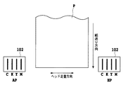
101はインクタンクであり、内部のインクは不図示のインク路を通って、記録ヘッド102まで連通している。記録ヘッド102は、記録媒体Pと対峙するように設けられている。インクタンク101及び記録ヘッド102はキャリッジ106に搭載されており、これら記録ヘッドユニット(インクタンク101、記録ヘッド102、キャリッジ106を含むユニット)は、非記録時はホームポジションHPに停止している。記録時は、ホームポジションからガイドレール107に沿って矢印X方向にキャリッジ106が移動し、この移動時に記録ヘッド102よりインクを吐出して記録を行う。ホームポジションから記録媒体をはさんで矢印X方向に向かっての基準位置をアウェイポジションAPという。キャリッジ106が記録媒体Pのアウェイポジション側の端まで移動すると、給紙ローラ105の回転によって、記録媒体が矢印Y方向に一定量だけ搬送される。給紙ローラ105の回転に伴い、搬送ローラ103、104も回転し、記録媒体Pを排紙方向へ送っていく。記録ヘッド102の移動による記録と給紙ローラ105、搬送ローラ103、104の回転による紙送りとを交互に繰り返すことにより、記録媒体P全体に記録を行うことができる。
(Embodiment 1)
FIG. 1 is a perspective view of an ink jet recording apparatus according to this embodiment.
インクタンク101は、ホームポジションから矢印X方向(主走査方向)に、マゼンタ、イエロー、ブラック、シアンの順に並んでいる。記録ヘッド102の主走査方向における各色ノズル列の並び順もインクタンク101と同様である。
The
図2は、記録ヘッドのノズル列を示す模式図である。
シアン(C)、ブラック(K)、イエロー(Y)、マゼンタ(M)の各色インクを吐出する各色ノズル列が、ノズルの配列方向とほぼ直交する方向、すなわち主走査方向において平行に配列されている。ノズル列は複数のノズルが一列または複数列に配列されたものである。各ノズルに対応して電気熱変換体であるヒータが設けられており、このヒータを発熱させることでインク中に気泡を発生させ、この気泡の生成圧力によって、インクを滴として吐出する。なお、本実施形態においては、インク吐出方式として、バブルジェット(登録商標)方式を用いているが、本発明はこれに限らず、ピエゾ方式など他の方式であってもよい。なお、本実施形態では、使用する各色ノズル列の全てが一体となった記録ヘッドを用いているが、本発明はこれに限らず、各色ノズル列が異なる記録ヘッドに設けられる形態でもよい。具体的には、本実施形態では、シアン(C)・マゼンタ(M)・イエロー(Y)・ブラック(K)に対応する4色のノズル列が1つの記録ヘッドに設けられる形態を採用しているが、これら4色のノズル列の夫々が独立的に異なる記録ヘッドに設けられる形態であってもよい。この場合、1つの記録ヘッドにつき1色のノズル列が設けられるため、計4個の記録ヘッドとなる。更には、これら4色のノズル列のうち、特定色(例えば、C・K)を一方の記録ヘッドに設け、特定色以外の色(例えば、M・Y)を他方の記録ヘッドに設ける形態であってもよい。
FIG. 2 is a schematic diagram illustrating nozzle rows of the recording head.
Each color nozzle row that ejects cyan (C), black (K), yellow (Y), and magenta (M) color inks is arranged in parallel in the direction substantially perpendicular to the nozzle arrangement direction, that is, in the main scanning direction. Yes. The nozzle row is a plurality of nozzles arranged in one or more rows. A heater, which is an electrothermal converter, is provided corresponding to each nozzle. By generating heat, the heater generates air bubbles, and ink is ejected as droplets by the generation pressure of the bubbles. In this embodiment, the bubble jet (registered trademark) method is used as the ink ejection method, but the present invention is not limited to this, and other methods such as a piezo method may be used. In this embodiment, the print head in which all the color nozzle rows to be used are integrated is used. However, the present invention is not limited to this, and a configuration in which each color nozzle row is provided in different print heads may be used. Specifically, in the present embodiment, a configuration is adopted in which nozzles of four colors corresponding to cyan (C), magenta (M), yellow (Y), and black (K) are provided in one recording head. However, each of these four color nozzle arrays may be independently provided in different recording heads. In this case, since one color nozzle row is provided for each recording head, there are a total of four recording heads. Further, of these four nozzle arrays, a specific color (for example, C · K) is provided in one recording head, and a color other than the specific color (for example, MY) is provided in the other recording head. There may be.
また、本実施形態では、上記4色のノズル列が同じ記録ヘッドの1つのヘッドチップに形成される形態であるが、本発明はこれに限定されるものではなく、各色ノズル列が同じ記録ヘッドの異なるチップに形成される構成であってもよい。具体的には、本実施形態では、シアン(C)・マゼンタ(M)・イエロー(Y)・ブラック(K)に対応する4色のノズル列が1つの記録ヘッドの1つのヘッドチップに設けられる形態を採用しているが、これら4色のノズル列の夫々が独立的に異なるチップに設けられる形態(この場合、1つのチップにつき1色のノズル列が設けられるため、計4個のチップとなる)であってもよい。更には、これら4色のノズル列のうち、特定色(例えば、C・K)を一方のヘッドチップに設け、特定色以外の色(例えば、M・Y)を他方のヘッドチップに設ける形態であってもよい。因みに、これら4色ノズル列が異なる記録ヘッドに設けられる形態の場合、当然、各色ノズル列のうち、少なくとも1つのノズル列が別チップに形成されることになることはいうまでもない。 In the present embodiment, the four color nozzle rows are formed on one head chip of the same print head. However, the present invention is not limited to this, and each color nozzle row has the same print head. The structure formed in a different chip | tip may be sufficient. Specifically, in this embodiment, four color nozzle rows corresponding to cyan (C), magenta (M), yellow (Y), and black (K) are provided in one head chip of one recording head. Although the form is adopted, each of these four color nozzle arrays is independently provided on different chips (in this case, since one color nozzle array is provided for each chip, a total of four chips and It may be). Further, of these four color nozzle arrays, a specific color (for example, C · K) is provided in one head chip, and a color other than the specific color (for example, MY) is provided in the other head chip. There may be. Incidentally, in the case where these four color nozzle arrays are provided in different recording heads, it goes without saying that at least one nozzle array of each color nozzle array is formed in a separate chip.
以上のように本発明では、各インク色に対応した各色ノズル列が同じ記録ヘッドや同じチップに設けられる形態のみならず、異なる記録ヘッドや異なるチップに設けられる形態も包含するものである。従って、これら形態を包含するべく、本発明では、各インク色に対応した各色ノズル列を含む構成を「記録部(あるいはインク吐出部)」と称する。なお、各インク色に対応した各色ノズル列を含む構成を「記録部(あるいはインク吐出部)」と称することは、後述する第2〜第4の実施形態においても同様である。 As described above, the present invention includes not only a mode in which each color nozzle row corresponding to each ink color is provided in the same recording head or the same chip, but also a mode in which different color recording heads or different chips are provided. Therefore, in order to include these forms, in the present invention, a configuration including each color nozzle row corresponding to each ink color is referred to as a “recording unit (or ink ejection unit)”. Note that a configuration including each color nozzle row corresponding to each ink color is referred to as a “recording unit (or ink ejection unit)” in the second to fourth embodiments described later.
上記図2で示したノズル列の並びであれば、キャリッジが矢印X方向に移動しているとき、すなわち往走査(往方向への主走査)のときに、記録媒体の同一領域に打ち込まれるインクの順は、シアン、ブラック、イエロー、マゼンタとなる。例えば、カラー記録でシアンとマゼンタの二次色(ブルー)を作る場合、先にシアンが打ち込まれ、次にマゼンタが打ち込まれることになる。一方、アウェイポジション側からホームポジション側へキャリッジが移動しているとき、すなわち復走査(復方向への主走査)のときに、記録媒体の同一領域に打ち込まれるインクの順は、マゼンタ、イエロー、ブラック、シアンとなる。同じくシアンとマゼンタの二次色(ブルー)を作る場合、先にマゼンタが打ち込まれ、次にシアンが打ち込まれることになる。つまり、往走査と復走査で色の重ね順序が異なる。 In the case of the arrangement of the nozzle rows shown in FIG. 2, ink that is driven into the same area of the recording medium when the carriage moves in the arrow X direction, that is, during forward scanning (main scanning in the forward direction). The order is cyan, black, yellow, and magenta. For example, when producing a secondary color (blue) of cyan and magenta in color recording, cyan is driven first and then magenta is driven. On the other hand, when the carriage moves from the away position side to the home position side, that is, in the backward scanning (main scanning in the backward direction), the order of the inks that are ejected into the same area of the recording medium is magenta, yellow, Black and cyan. Similarly, when making a secondary color (blue) of cyan and magenta, magenta is first driven and then cyan is driven. That is, the order of color superposition differs between forward scanning and backward scanning.
次に、インクが記録媒体に打ち込まれてからドットを形成するまでの様子を、図3(a)〜図3(f)を参照しながら説明する。同図はインクの着弾面を示す記録媒体の断面図である。図3(a)に示すように、記録媒体はインク吸収層と染料吸着層の2層構造になっている。図2に示される矢印X方向にキャリッジが移動している場合、まずシアンインクが最初に記録媒体に着弾する。シアンインクは染料と溶剤及び水などから構成されており、着弾したシアンインクのインク滴は、図3(b)に示すように、シアン染料が染料吸着層の表層に近い位置にトラップされる。一方、染料以外の溶剤や水分等その他については、記録媒体の内部に向かって浸透していき、図3(c)に示すように、染料吸着層を通過してインク吸収層に到達し、吸収される。もちろん、インクが着弾してから、若干量の溶剤、水分等が表層から外部に蒸発するのは、言うまでもない。 Next, the state from when the ink is ejected to the recording medium until the dot is formed will be described with reference to FIGS. 3 (a) to 3 (f). FIG. 2 is a cross-sectional view of the recording medium showing the ink landing surface. As shown in FIG. 3A, the recording medium has a two-layer structure of an ink absorption layer and a dye adsorption layer. When the carriage is moving in the direction of the arrow X shown in FIG. 2, the cyan ink first lands on the recording medium. The cyan ink is composed of a dye, a solvent, water, and the like, and the ink droplets of the landed cyan ink are trapped at a position close to the surface layer of the dye adsorption layer as shown in FIG. 3B. On the other hand, solvents, moisture, and the like other than the dye penetrate into the inside of the recording medium, pass through the dye adsorption layer, reach the ink absorption layer, and absorb as shown in FIG. Is done. Of course, it goes without saying that a small amount of solvent, moisture, and the like evaporate from the surface layer to the outside after the ink has landed.
次に図3(d)に示すように、シアンインクが吐出された後にマゼンタインクが吐出され、マゼンタインクが着弾する。図3(e)に示すように、記録媒体表層にはシアン染料が既にトラップされているので、その上、さらにマゼンタ染料を吸着する余裕がない。そこで、着弾したマゼンタ染料は、染料吸着層における、まだシアン染料がトラップされていない位置にトラップされる。そして、図3(f)に示すように、染料以外の溶剤その他については、インク吸収層に吸収される。シアンインクの溶剤がインク吸収層に吸収されたのちにマゼンタインクが着弾しているので、マゼンタインクは記録媒体の内部方向に大きく沈みこまずに、表層部分にもマゼンタ染料が一部トラップする形で定着する。 Next, as shown in FIG. 3D, the magenta ink is ejected after the cyan ink is ejected, and the magenta ink is landed. As shown in FIG. 3E, since the cyan dye is already trapped on the surface layer of the recording medium, there is no room for further adsorbing the magenta dye. Therefore, the landed magenta dye is trapped at a position in the dye adsorption layer where the cyan dye is not yet trapped. And as shown in FIG.3 (f), solvent other than dye is absorbed by the ink absorption layer. Since the magenta ink has landed after the cyan ink solvent is absorbed by the ink absorbing layer, the magenta ink does not sink greatly in the internal direction of the recording medium, and the magenta dye partially traps in the surface layer portion. To fix.
往方向の印刷の際の着弾断面を示す図3(a)〜図3(f)に対して、復方向の印刷の際に着弾してからドットが形成されるまでの様子を示す図を、図14(a)〜図14(f)に記載する。ここで、図3(f)と図14(f)を比較すると、先に着弾したインクの染料がより、メディア表層に定着するために、ドットの色味差が発生する。 FIG. 3A to FIG. 3F showing the landing cross section in the forward printing, and FIG. 3F is a diagram showing the state from the landing to the dot formation in the backward printing. It describes in Fig.14 (a)-FIG.14 (f). Here, when FIG. 3F and FIG. 14F are compared, since the dye of the ink that has landed earlier is more firmly fixed on the media surface layer, a color difference of dots occurs.
このようなインク浸透の過程において、染料が染料吸着層にトラップされ、溶剤等がインク吸収層に吸収されるまで、数10msほど浸透時間を要するため、先に着弾したインクの浸透が十分に行われないうちに、次のインクが着弾すると次のような状態(下記図4(a)〜図4(d)に示すような状態)が発生する。 In the ink penetration process, it takes about several tens of milliseconds for the dye to be trapped in the dye adsorption layer and the solvent or the like to be absorbed in the ink absorption layer. Before the next ink lands, the following states (states shown in FIGS. 4A to 4D below) occur.
図4(a)〜図4(d)はシアンインクが十分浸透しない状態でマゼンタインクが打ち込まれた場合を示す図である。図4(b)に示すように、先に着弾したシアンインクの溶剤成分がまだインク吸収層まで十分に浸透せず染料吸着層の中で残留している状態で、マゼンタインクが打ち込まれると、図4(c)に示すように、染料吸着層部分において、シアンインクの溶剤とマゼンタインクの溶剤が留まり溶剤過多の状態となる。このように、溶剤が染料吸着層中で過多の状態になると、溶剤と染料を含むインクの表面張力が、染料吸着力に対して相対的に大きくなり、図4(d)に示すように、染料吸着層に吸着せずに、メディア内部のインク吸収層に溶剤成分と共に浸透してしまう染料の割合が増加する。従って、異なる2つのインク色の着弾時間差が短くなればなるほど、後から着弾したインクの染料成分は記録媒体の下層方向に吸着する割合が増えることとなる。染料はメディア表層からの吸着位置が下層に落ちるほど発色には寄与しなくなる。 FIGS. 4A to 4D are diagrams illustrating a case where magenta ink is printed in a state where cyan ink does not sufficiently permeate. As shown in FIG. 4B, when the magenta ink is driven in a state where the solvent component of the cyan ink that has landed first does not sufficiently penetrate the ink absorption layer and remains in the dye adsorption layer, As shown in FIG. 4C, the cyan ink solvent and the magenta ink solvent remain in the dye adsorption layer portion, resulting in an excessive solvent state. Thus, when the solvent becomes excessive in the dye adsorption layer, the surface tension of the ink containing the solvent and the dye becomes relatively large with respect to the dye adsorption force, and as shown in FIG. The ratio of the dye that does not adsorb to the dye adsorbing layer and permeates with the solvent component into the ink absorbing layer inside the medium increases. Therefore, the shorter the landing time difference between two different ink colors, the higher the rate at which the dye component of the ink that has landed later is adsorbed in the lower layer direction of the recording medium. The dye does not contribute to color development as the adsorption position from the media surface layer falls to the lower layer.
図5(a)〜図5(d)は、図4(a)〜図4(d)の走査方向とは逆の方向に記録ヘッドが走査したときのシアンとマゼンタインクの着弾状態を示す図である。すなわち、マゼンタインクが先に着弾し、後からシアンインクが着弾した場合を示す。図4(d)と図5(d)を比べてみてわかるように、2色間の着弾時間差が小さい場合、後から着弾したインクの染料はほとんど記録媒体の表層に残らないので、インクの重ね順による色味差がより大きくなってしまう。 FIGS. 5A to 5D are diagrams showing the landing states of cyan and magenta ink when the recording head scans in the direction opposite to the scanning direction of FIGS. 4A to 4D. It is. That is, the case where the magenta ink landed first and the cyan ink landed later is shown. As can be seen by comparing FIG. 4D and FIG. 5D, when the landing time difference between the two colors is small, the ink that has landed afterwards hardly remains on the surface of the recording medium. The color difference due to the order becomes larger.
これは、前述した、インクの着弾時間差が比較的大きい図3(f)および図14(f)に示す着弾状態は、後に着弾したインク染料はメディア表層により多く定着し、発色に一定量寄与するため、往復の色味差は比較的小さい。 This is because, in the landing state shown in FIGS. 3 (f) and 14 (f), where the ink landing time difference is relatively large as described above, the ink dye that has landed later is fixed more on the media surface layer, contributing to a certain amount of color development. Therefore, the round trip color difference is relatively small.
したがって、二次色の記録を行うにあたり、往走査と復走査で色味差を抑えるためには、先に着弾したインクが記録媒体に十分浸透してから次のインクを着弾させることが有効である。つまり、往走査と復走査でインクの重なり順が異なることに起因して生じる「色味差」を軽減するには、2色の着弾時間差を考慮することが非常に重要なのである。そして、上記2色の着弾時間差を長くすることにより上記色味差が軽減される。言い換えれば、上記2色のノズル列間の距離を大きくすることにより上記色味差が軽減されるのである。 Therefore, when performing secondary color recording, in order to suppress the color difference between forward scanning and backward scanning, it is effective to land the next ink after the previously landed ink has sufficiently penetrated the recording medium. is there. In other words, it is very important to consider the landing time difference between the two colors in order to reduce the “color difference” caused by the difference in the overlapping order of ink between the forward scan and the backward scan. And the said color difference is reduced by lengthening the landing time difference of said 2 colors. In other words, the color difference is reduced by increasing the distance between the nozzle rows of the two colors.
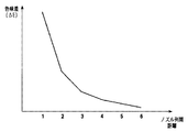
このことは、図6から明らかである。図6は、ノズル列間距離と色味差の関係を示した図である。ここで、ノズル列間距離としては、隣接するノズル列間の距離を「1」と定義している。従って、例えば、CMYK4色に対応する4つのノズル列を主走査方向に等間隔に平行に並べれば、最も離れた距離に配置される2色のノズル列間距離は「3」となる。なお、同図では、二次色を形成する2色としてシアンとマゼンタを用いた際の色味差を示している。この図6から明らかなように、二次色(ブルー)を形成する2色のノズル列間の距離が離れるほど、形成される二次色のインクの重ね順の違いによる「色味差」は小さくなることがわかる。これは、上述したように、ノズル列間距離が大きいほど着弾時間差が長くなることに他ならない。 This is clear from FIG. FIG. 6 is a diagram showing the relationship between the distance between the nozzle rows and the color difference. Here, as the distance between nozzle rows, the distance between adjacent nozzle rows is defined as “1”. Therefore, for example, if four nozzle rows corresponding to four colors of CMYK are arranged in parallel in the main scanning direction at equal intervals, the distance between the nozzle rows of the two colors arranged at the farthest distance is “3”. In the figure, the color difference is shown when cyan and magenta are used as the two colors forming the secondary color. As is apparent from FIG. 6, the “color difference” due to the difference in the overlapping order of the formed secondary color inks increases as the distance between the nozzle rows of the two colors forming the secondary color (blue) increases. It turns out that it becomes small. As described above, this is nothing but the difference in landing time becomes longer as the distance between nozzle rows is larger.
また二次色のインクの重ね順序の違いによって色味差が発生する現象は、シアン・マゼンタインクの組み合わせのみならず、他のインク同士の組み合わせでも起こりうる。しかし、このインクの重なり順の違いによる色味差(色差)は、インクの組み合わせによって異なり、一般的にインク色間の色相差が大きいほど、上記色味差も大きくなる。そこで、インク色間の色相差が大きい2色の組み合わせにおいて、二次色の色味差を抑えるためには、図3(a)〜図3(f)に示すように、色相差が大きい2色のインクの着弾時間差を大きくとることが有効である。すなわち、インク色間の色相差が大きい2色は、ノズル列間の距離をできる限り離れるように配置したほうが良いと考えられる。
Further, the phenomenon in which a color difference occurs due to the difference in the order of the secondary color inks can occur not only in the combination of cyan and magenta inks but also in the combination of other inks. However, the color difference (color difference) due to the difference in the overlapping order of the inks varies depending on the combination of the inks. Generally, as the hue difference between the ink colors increases, the color difference increases. Therefore, in order to suppress the color difference between the secondary colors in a combination of two colors having a large hue difference between the ink colors, as shown in FIGS. 3A to 3F, the
そこで、本実施形態では、イエロー、シアン、マゼンタの中でもっとも色相差の大きい関係となるシアンとマゼンタについて、それぞれのノズル列がもっとも離れた関係となるように、ノズルの配列方向(所定方向)と直交する方向(主走査方向)におけるノズル列の並び順をシアン、ブラック、イエロー、マゼンタの順としている。すなわち、図2に示されるように、各色ノズル列の主走査方向における並び順としては、色相差が最も大きい2色のノズル列が両端部に位置するような並び順としているのである。なお、ブラックを用いて二次色を形成することはほとんどないので、色相差の関係はカラーインク間で判断すればよい。 Therefore, in the present embodiment, the nozzle arrangement direction (predetermined direction) is set so that the nozzle arrays are most distant from each other for cyan and magenta that have the largest hue difference among yellow, cyan, and magenta. The order of arrangement of the nozzle rows in the direction orthogonal to (the main scanning direction) is cyan, black, yellow, and magenta. That is, as shown in FIG. 2, the arrangement order of the color nozzle arrays in the main scanning direction is such that the two color nozzle arrays having the largest hue difference are located at both ends. Since a secondary color is hardly formed using black, the relationship between hue differences may be determined between color inks.
因みに、従来の横並び記録ヘッドは、シアン用ノズル列、マゼンタ用ノズル列、イエロー用ノズル列、ブラック用ノズル列の順で主走査方向に並んでいる場合が多い。この形態では、複数色のなかで色相差が最も大きい2色(シアンとマゼンタ)のノズル列が互いに隣接な配置となっているため、2色の着弾時間差は比較的短く、これに伴って、往復走査でのインク重なり順の違いによる色味差が比較的大きくなってしまう。一方、本実施形態の場合、複数色のなかで色相差が最も大きい2色(シアンとマゼンタ)のノズル列は最も離れた両端部に配置されているため、2色の着弾時間差は比較的長くなり、これに伴って、往復走査でのインク重なり順の違いによる色味差が比較的小さて済む。以上のように本実施形態の場合、従来の記録ヘッドを用いる場合に比べ、シアン、マゼンタによる二次色の色むらが抑制されることになる。 Incidentally, a conventional side-by-side recording head is often arranged in the main scanning direction in the order of a cyan nozzle row, a magenta nozzle row, a yellow nozzle row, and a black nozzle row. In this embodiment, since the nozzle rows of the two colors (cyan and magenta) having the largest hue difference among the plurality of colors are arranged adjacent to each other, the landing time difference between the two colors is relatively short. The color difference due to the difference in the ink overlapping order in the reciprocating scanning becomes relatively large. On the other hand, in the case of the present embodiment, since the nozzle rows of the two colors (cyan and magenta) having the largest hue difference among a plurality of colors are arranged at the farthest ends, the landing time difference between the two colors is relatively long. Accordingly, the color difference due to the difference in the ink overlapping order in the reciprocating scan can be relatively small. As described above, in the case of the present embodiment, the color unevenness of the secondary color due to cyan and magenta is suppressed as compared with the case where the conventional recording head is used.
さらに、図4(a)〜図4(d)、図5(a)〜図5(d)に示したように、往復記録時の色の重ね順による色むらは、往印字と復印字の際の、先に着弾したインクが記録媒体の染料吸着層のどの位置に吸着するかに関わってくる。すなわち、往印字と復印字での吸着ポイントが異なるほど、往復記録の色味差が大きくなる。我々の実験で使用したシアンインクは吸着ポイントが最も表層に近く、マゼンタインクはメディア内部の下層に沈みやすい性質を持っていた。前述したインク色間の色相差が同等の組み合わせであっても、この染料吸着ポイントの差が最も大きいインク色の組み合わせを、色間距離が最も離れるように配置する。 Further, as shown in FIGS. 4A to 4D and FIGS. 5A to 5D, the color unevenness due to the overlapping order of the colors in the reciprocal recording is the forward printing and the backward printing. At this time, it is related to which position of the ink adsorbing layer of the recording medium the ink landed first. That is, as the suction points for forward printing and reverse printing differ, the color difference in reciprocal recording increases. The cyan ink used in our experiment had the closest adsorption point to the surface layer, and magenta ink had the property of being easily sunk in the lower layer inside the media. Even if the above-described hue difference between ink colors is the same, the combination of ink colors having the largest difference in the dye adsorption points is arranged so that the distance between colors is the longest.
以上のように、色相差がもっとも大きく、かつ染料吸着ポイントの差がもっとも大きいインク色の組み合わせを、ノズル列間距離がもっとも離れるように配置することで、往復記録時の色むらを低減することができる。 As described above, by arranging the combination of ink colors with the largest hue difference and the largest difference in dye adsorption point so that the distance between the nozzle rows is the longest, color unevenness during reciprocal recording can be reduced. Can do.
以上、本実施形態によれば、4色に対応する各色ノズル列を含む記録部(インク吐出部)を使用して記録を行うにあたり、これら複数色の中で最も色相差が大きい2色(本実施形態では、CとM)の着弾時間差が比較的大となるよう、色相差が最も大きい2色のノズル列を記録部の主走査方向における両端に配置する構成としたため、最も色相差が大きい2色(CとM)の着弾時間差が長くなり、往復走査でのインク重なり順の違いによる色味差が小さくなる。 As described above, according to the present embodiment, when recording is performed using a recording unit (ink ejection unit) including each color nozzle row corresponding to four colors, two colors (books) having the largest hue difference among the plurality of colors are used. In the embodiment, since the two-color nozzle rows having the largest hue difference are arranged at both ends in the main scanning direction of the recording unit so that the difference in landing time between C and M) is relatively large, the hue difference is the largest. The landing time difference between the two colors (C and M) becomes long, and the color difference due to the difference in the ink overlapping order in the reciprocating scanning becomes small.
また、別の観点からすると、本実施形態では、ノズルの配列方向と直交する方向における各色ノズル列の並び順として、色相差が最も大きい2色のノズル列の間に、当該2色以外の色のノズル列を2つ以上配列した並び順としたため、最も色相差が大きい2色(CとM)の着弾時間差が比較的長くなり、往復走査でのインク重なり順の違いによる色味差を軽減できる。 From another point of view, in this embodiment, as the arrangement order of the color nozzle rows in the direction orthogonal to the nozzle arrangement direction, colors other than the two colors are arranged between the two color nozzle rows having the largest hue difference. The order of arrangement of two or more nozzle rows is relatively long, so the landing time difference between the two colors with the largest hue difference (C and M) is relatively long, reducing the difference in color due to the difference in the ink overlap order during reciprocating scanning. it can.
更には、本実施形態では、ブラックインクが2次色の形成にほとんど使用されない点を考慮し、ブラックを含む4色に対応する各色ノズル列を含む記録部(インク吐出部)を使用して記録を行うにあたり、ブラックを除く3色の中で最も色相差が大きい2色(CとM)の着弾時間差が比較的大となるよう、色相差が最も大きい2色のノズル列がカラーノズル列間において最も離れるよう配置した。したがって、最も色相差が大きい2色(CとM)の着弾時間差が長くなり、往復走査でのインク重なり順の違いによる色味差が小さくなる。 Furthermore, in this embodiment, in consideration of the fact that black ink is hardly used for forming a secondary color, recording is performed using a recording unit (ink ejection unit) including each color nozzle row corresponding to four colors including black. In order to make the landing time difference between the two colors (C and M) with the largest hue difference among the three colors excluding black, the two color nozzle rows with the largest hue difference are between the color nozzle rows. Placed farthest away. Therefore, the landing time difference between the two colors (C and M) having the largest hue difference becomes longer, and the hue difference due to the difference in the ink overlapping order in the reciprocating scanning becomes smaller.
(実施形態2)
実施形態1では、使用されるインクがシアン、マゼンタ、イエロー、ブラックの4色の場合を説明したが、高画質化を追及するために、ここにさらに淡シアン、淡マゼンタを加えた6色構成のインクジェット記録装置も普及している。そこで、本実施形態では上記6色構成の場合について説明する。
(Embodiment 2)
In the first embodiment, the case where the inks used are four colors of cyan, magenta, yellow, and black has been described. However, in order to pursue high image quality, a six-color configuration in which light cyan and light magenta are further added thereto. Inkjet recording apparatuses are also widespread. Therefore, in the present embodiment, the case of the six-color configuration will be described.
インクジェット記録装置の装置構成は実施形態1と同様とするが、記録ヘッドの構成は下記図7に示すようになっている。図7は、本実施形態における記録ヘッドの各色ノズル列の並びを示す模式図である。図7から明らかなように、ノズルの配列方向と直交する方向において、シアン(C)・ライトシアン(LC)・ブラック(K)・イエロー(Y)・ライトマゼンタ(LM)・マゼンタ(M)の各色ノズル列がこの順で配列されている。そして、この実施形態においても、使用する複数色のうち、色相差がもっとも大きい2色(シアンとマゼンタ)のノズル列の間に当該2色(シアンとマゼンタ)以外の少なくとも2つのノズル列が配列されており、色相差が最も大きい2色のインク着弾時間差が比較的長くなるよう構成されている。 The apparatus configuration of the inkjet recording apparatus is the same as that of the first embodiment, but the configuration of the recording head is as shown in FIG. FIG. 7 is a schematic diagram showing the arrangement of each color nozzle row of the recording head in the present embodiment. As is apparent from FIG. 7, each color of cyan (C), light cyan (LC), black (K), yellow (Y), light magenta (LM), and magenta (M) in the direction orthogonal to the nozzle arrangement direction. Nozzle rows are arranged in this order. Also in this embodiment, at least two nozzle rows other than the two colors (cyan and magenta) are arranged between the nozzle rows of the two colors (cyan and magenta) having the largest hue difference among the plurality of colors to be used. The difference between the ink landing times of the two colors having the largest hue difference is relatively long.
図8は、記録ヘッドの主走査方向に対する各色ノズル列の並びを示す模式図である。図に示すように、ホームポジションからアウェイ方向に向かって先頭より、シアン(C)、ライトシアン(LC)、ブラック(K)、イエロー(Y)、ライトマゼンタ(LM)、マゼンタ(M)の順で、それぞれのノズル列が平行になるように等間隔に配列されている。実施形態1と同様、本実施形態においても、2色間の色相差がもっとも大きいシアンとマゼンタが主走査方向において両端となるように配置し、シアン、マゼンタの2色間距離がもっとも大きくなるようにしている。ここで、濃インクと淡インクは通常同一色相となるため、この場合は、往復記録の際の色差が大きい濃インクの中で、色相差が最も大きい2色のノズル列を最も離して配置することが好ましい。なお、図6から明らかなように、隣接するノズル列間の距離を「1」とした場合、本実施形態における記録部のシアン用ノズル列とマゼンタ用ノズル列との間の距離は「5」となる。 FIG. 8 is a schematic diagram showing the arrangement of each color nozzle row in the main scanning direction of the recording head. As shown in the figure, from the head toward the away direction from the home position, cyan (C), light cyan (LC), black (K), yellow (Y), light magenta (LM), and magenta (M) in this order. The nozzle rows are arranged at equal intervals so as to be parallel. Similar to the first embodiment, in this embodiment, cyan and magenta having the largest hue difference between the two colors are arranged at both ends in the main scanning direction so that the distance between the two colors of cyan and magenta is the largest. I have to. Here, since the dark ink and the light ink usually have the same hue, in this case, among the dark inks having a large color difference during reciprocal recording, the two color nozzle rows having the largest hue difference are arranged farthest apart. It is preferable. As is apparent from FIG. 6, when the distance between adjacent nozzle rows is “1”, the distance between the cyan nozzle row and the magenta nozzle row of the recording unit in this embodiment is “5”. It becomes.
図6に示すように、ノズル列間距離が「5」の場合、インクの重ね順序の違いによる色味差は大きく減少する。例えば、実施形態1における記録ヘッドでは、シアン、マゼンタ間のノズル列間距離は3であり、このときの色差と比較しても、大きく減少していることが分かる。 As shown in FIG. 6, when the inter-nozzle row distance is “5”, the color difference due to the difference in the ink stacking order is greatly reduced. For example, in the recording head according to the first embodiment, the distance between the nozzle rows between cyan and magenta is 3, and it can be seen that the distance is greatly reduced compared to the color difference at this time.
6色のインク色のヘッドを横並びに配列したときに、マゼンタとシアンを最外位置におくことが、色むらによる画像品質の低下を防ぐ上でもっとも有効となる。ここでブラックインクを除いた理由は、他の色のインクと異なり、ブラックと他の1色による二次色を形成することはほとんどなく、ブラックインクを高デューティで使用する際には、他のインクのデューティは低く、逆に他のインクのデューティが高い時にはブラックインクのデューティは低いことから、原理的に往復記録の時の色むらが目立ちにくい。したがってブラックインクは組み合わせから除外している。さらに、淡シアンはシアンの隣に、淡マゼンタはマゼンタの隣にそれぞれ配置している。これは、濃インクと淡インクを両方同時に100%に近い高デューティで記録することは画像設計上ほとんどありえないため、記録ヘッドの昇温の観点から考えると、濃淡インクは近接させ、他のインクは近接しないように配置することが好ましいからである。 When the six ink color heads are arranged side by side, placing magenta and cyan at the outermost positions is most effective in preventing deterioration in image quality due to color unevenness. The reason for removing the black ink here is that unlike the inks of other colors, there is almost no formation of a secondary color of black and the other one color. Since the duty of the ink is low and the duty of the black ink is low when the duty of the other ink is high, the color unevenness at the time of reciprocal recording is hardly noticeable in principle. Therefore, black ink is excluded from the combination. Further, light cyan is arranged next to cyan, and light magenta is arranged next to magenta. This is because it is almost impossible in terms of image design to record both dark ink and light ink at a high duty close to 100% at the same time. From the viewpoint of the temperature rise of the recording head, the dark ink and the other ink are close to each other. It is because it is preferable to arrange so that it does not adjoin.
また、実施形態1でも説明したように、インク染料の記録媒体上での吸着ポイントについても注意する必要がある。我々の実験で使用したシアンインクは吸着ポイントが最も表層に近く、マゼンタインクはメディア内部の下層に沈みやすい性質を持っている。そこで、前述したインク色間の色相差が同等の組み合わせであっても、この染料吸着ポイントの差が最も大きいインク色の組み合わせを、色間距離が最も離れるように配置する必要がある。この場合においても、シアンとマゼンタをもっとも離して配置することで、染料の吸着ポイントの観点についても有効な結果をもたらすことができる。 In addition, as described in the first embodiment, it is necessary to pay attention to the suction point of the ink dye on the recording medium. The cyan ink used in our experiment has the closest adsorption point to the surface layer, and magenta ink has the property of being easily sunk in the lower layer inside the media. Therefore, even if the hue difference between the ink colors described above is the same, it is necessary to arrange the combination of the ink colors having the largest difference in the dye adsorption points so that the distance between the colors is the longest. Even in this case, by arranging cyan and magenta farthest from each other, an effective result can be brought about also in terms of the adsorption point of the dye.
以上のように、6色インクの横並びヘッドにおいて、往復記録をした際のインクの重なり順による色差が最も大きいインクの組み合わせ、すなわち本実施形態ではシアン、マゼンタインクを最もノズル列間距離が離れるように配置し、他のインク色も同様に色むらが許容可能な列間距離によりノズル列並びを構成することで、往復記録時の色むらを低減することができる。 As described above, in the six-color ink side-by-side heads, the combination of inks having the largest color difference due to the overlapping order of the inks when performing reciprocal recording, that is, the cyan and magenta inks in this embodiment are the most distant from each other. By arranging the nozzle rows in such a manner that the other ink colors are similarly arranged with the distance between the rows in which the color unevenness can be tolerated, the color unevenness during the reciprocal recording can be reduced.
以上、本実施形態によれば、6色に対応する各色ノズル列を含む記録部(インク吐出部)を使用して記録を行うにあたり、これら複数色の中で最も色相差が大きい2色(本実施形態では、CとM)の着弾時間差が比較的大となるよう、色相差が最も大きい2色のノズル列を記録部の主走査方向における両端に配置する構成とした。そのため、最も色相差が大きい2色(CとM)の着弾時間差が長くなり、往復走査でのインク重なり順の違いによる色味差が小さくなる。 As described above, according to the present embodiment, when recording is performed using a recording unit (ink ejection unit) including each color nozzle row corresponding to six colors, two colors (the main color difference) having the largest hue difference among these multiple colors are used. In the embodiment, the nozzle arrays of two colors having the largest hue difference are arranged at both ends in the main scanning direction of the recording unit so that the difference in landing time between C and M) is relatively large. Therefore, the landing time difference between the two colors (C and M) having the largest hue difference becomes longer, and the hue difference due to the difference in the ink overlapping order in the reciprocating scanning becomes smaller.
(実施形態3)
一般的に、記録装置は文書などのモノクロ画像を記録する割合が比較的高く、カラーインクとブラックインクの使用量を比較すると、ブラックインクの方が多い。そこで、インク交換回数の低減などからブラックインクのタンク容量を他のカラーインクに比べて大きくした構成のものも提供されている。このような場合、ブラックインクタンクをもっとも外側に配置すると、タンク交換などのユーザの使い勝手がよい。また、複数色分のノズル列を有するヘッドとインクタンクとの接続は、ノズル列とインクタンクとをストレートに接続した方がインク流路の引き回しを最小限にとどめることができ、好ましい。
(Embodiment 3)
In general, a recording apparatus has a relatively high ratio of recording a monochrome image such as a document, and the amount of black ink is larger than the amount of color ink and black ink used. In view of this, a configuration in which the tank capacity of the black ink is increased as compared with other color inks is provided in order to reduce the number of ink replacements. In such a case, if the black ink tank is arranged on the outermost side, user convenience such as tank replacement is good. Further, the connection between the heads having the nozzle rows for a plurality of colors and the ink tanks is preferable if the nozzle rows and the ink tanks are connected in a straight line because the ink flow path can be minimized.
そこで、本実施形態では、ブラックインクのノズル列を最外位置に配置するとともに、他のカラーインク(シアン、ライトシアン、イエロー、ライトマゼンタ、マゼンタ)については色の重ね順序の違いによる色味差をもっとも抑えることができる最適な配列の記録ヘッドについて説明する。 Therefore, in the present embodiment, the black ink nozzle row is arranged at the outermost position, and for the other color inks (cyan, light cyan, yellow, light magenta, magenta), the color difference due to the difference in the color overlapping order is obtained. An optimum arrangement of recording heads that can be suppressed most will be described.
図10は、本実施形態におけるヘッドの色並び順と、それに対するインクタンクの対応を模式的に示した図である。インクタンク1001から1006に対して、複数色分のノズル列を持つヘッドチップ1007への接続は、ストレートに接続したほうが、インク流路の引き回しの際に有利であるため、ヘッドチップ上の配置もブラックインクのノズル列は最外位置に配置される。
FIG. 10 is a diagram schematically showing the order of color arrangement of the heads and the corresponding ink tanks in the embodiment. For the
残りの5色の配列に関しては、実施形態1、2でも説明したように、往復記録による色むらが発生しにくいように、シアン、マゼンタインクのノズル列間距離がカラーチップ間で最も距離が離れるように配置する。したがって、カラー用インク吐出ノズル列の主走査方向における配列順序は、シアン、淡シアン、イエロー、淡マゼンタ、マゼンタの順となり、これらノズル列は主走査方向において等間隔に配列される。隣接するノズル列間の距離を「1」とすると、シアンとマゼンタの間の距離は「4」となり、インクの重ね順序の違いによる色差を抑えるための時間差を生むには十分な距離となる。したがって、このような構成の記録ヘッドであっても、実施形態1,2と同様にインクの重ね順序の違いによる色差に起因する「色むら」を抑えることができる。さらに、インクタンクとノズル列をストレートに配置することができるので、ヘッドチップ内でインク流路を複雑に這いまわす必要がなく、構成の複雑化による信頼性の低下をまねくことがない。 As for the remaining five colors, as described in the first and second embodiments, the distance between the nozzle rows of cyan and magenta inks is the longest between the color chips so that color unevenness due to reciprocal recording hardly occurs. Arrange so that. Accordingly, the order of arrangement of the color ink discharge nozzle rows in the main scanning direction is cyan, light cyan, yellow, light magenta, and magenta, and these nozzle rows are arranged at equal intervals in the main scanning direction. When the distance between adjacent nozzle rows is “1”, the distance between cyan and magenta is “4”, which is a sufficient distance to generate a time difference for suppressing a color difference due to a difference in the ink stacking order. Therefore, even in the recording head having such a configuration, “color unevenness” due to the color difference due to the difference in the ink stacking order can be suppressed as in the first and second embodiments. Further, since the ink tank and the nozzle row can be arranged straight, it is not necessary to complicatedly arrange the ink flow path in the head chip, and the reliability is not lowered due to the complicated configuration.
なお、本実施形態のように、ブラックインクを最も外側に配置しても、実施形態1,2と同様の効果が得られる理由の一つとしては、上述したように、ブラックインクは他の色のインクと異なり、ブラックと他の1色による二次色を形成することはほとんどなく、ブラックインクを高デューティで使用する際には、他のインクのデューティは低く、逆に他のインクのデューティが高い時にはブラックインクのデューティは低いことから、原理的に往復記録の時の色むらが目立ちにくいという特性があるからである。 Note that, as described above, as described above, even if the black ink is arranged on the outermost side, the same effect as in the first and second embodiments can be obtained. Unlike other inks, secondary colors of black and other one color are rarely formed. When black ink is used at a high duty, the duty of other inks is low, and conversely the duty of other inks This is because the duty of the black ink is low when the color is high, and in principle, the color unevenness at the time of reciprocal recording is not noticeable.
本実施形態のように構成することで、ユーザにとって使用上の違和感の少ない色並び順を提供できると同時に、往復記録時の色むらを回避し、かつ、複雑に流路を這いまわすことによる信頼性の低下も防ぐことが可能となる。 By configuring as in the present embodiment, it is possible to provide a user with a color arrangement order that is less uncomfortable for the user, and at the same time, avoids color unevenness during reciprocal recording and is reliable by complicatedly changing the flow path. It is also possible to prevent a decrease in sex.
以上、本実施形態では、ブラックインクが2次色の形成にほとんど使用されない点を考慮し、ブラックを含む6色に対応する各色ノズル列を含む記録部(インク吐出部)を使用して記録を行うにあたり、ブラックを除く5色の中で最も色相差が大きい2色(CとM)の着弾時間差が比較的大となるよう、色相差が最も大きい2色のノズル列がカラーノズル列間で最も離れるよう配置した。このため、最も色相差が大きい2色(CとM)の着弾時間差が長くなり、往復走査でのインク重なり順の違いによる色味差を小さく抑えることができる。 As described above, in this embodiment, in consideration of the fact that black ink is hardly used for forming a secondary color, recording is performed using a recording unit (ink ejection unit) including each color nozzle row corresponding to six colors including black. In doing so, the two color nozzle rows with the largest hue difference between the color nozzle rows so that the landing time difference between the two colors (C and M) with the largest hue difference among the five colors excluding black is relatively large. Arranged to be farthest away. For this reason, the landing time difference between the two colors (C and M) having the largest hue difference becomes long, and the color difference due to the difference in the ink overlapping order in the reciprocating scanning can be suppressed to a small value.
(実施形態4)
上記実施形態1〜実施形態3では、色相差が最も大きい2色のノズル列(Cノズル列とMノズル列)がカラーノズル列間で最も離れるよう配置している。しかし、本発明は、この構成に限定されるものではなく、色相差が最も大きい2色のノズル列の間に少なくとも2つのノズル列が配置された構成であればよい。以下、これに関して説明する。
(Embodiment 4)
In the first to third embodiments, the two color nozzle rows (C nozzle row and M nozzle row) having the largest hue difference are arranged so as to be farthest between the color nozzle rows. However, the present invention is not limited to this configuration, and any configuration may be used as long as at least two nozzle rows are arranged between the two color nozzle rows having the largest hue difference. This will be described below.
上述した実施形態1では、色相差が最も大きい2色のノズル列(Cノズル列とMノズル列)の間に2つのノズル列(Kノズル列、Yノズル列)が配列され、また、実施形態2では、色相差が最も大きい2色のノズル列(Cノズル列とMノズル列)の間に4つのノズル列(Kノズル列、Yノズル列、LMノズル列、LCノズル列)が配列され、また、実施形態3では、色相差が最も大きい2色のノズル列(Cノズル列とMノズル列)の間に3つのノズル列(Yノズル列、LMノズル列、LCノズル列)が配列されている。このように、色相差が最も大きい2色のノズル列(Cノズル列とMノズル列)がカラーノズル列間で最も離れるよう配列することが、色味差の低減に最も効果的であることは確かである。 In the first embodiment described above, two nozzle rows (K nozzle row and Y nozzle row) are arranged between the two color nozzle rows (C nozzle row and M nozzle row) having the largest hue difference. 2, four nozzle rows (K nozzle row, Y nozzle row, LM nozzle row, LC nozzle row) are arranged between nozzle rows of two colors having the largest hue difference (C nozzle row and M nozzle row), In the third embodiment, three nozzle rows (Y nozzle row, LM nozzle row, and LC nozzle row) are arranged between the two color nozzle rows (C nozzle row and M nozzle row) having the largest hue difference. Yes. As described above, arranging the two color nozzle rows (C nozzle row and M nozzle row) having the largest hue difference so as to be the farthest between the color nozzle rows is most effective in reducing the color difference. Certainly.
しかしながら、色相差が最も大きい2色のノズル列(Cノズル列とMノズル列)をカラーノズル列間で最も離した配列でなくとも、色味差の低減を図ることはできる。例えば、実施形態2では、色相差が最も大きい2色のノズル列(Cノズル列とMノズル列)の間に4つのノズル列(Kノズル列、Yノズル列、LMノズル列、LCノズル列)を配列しているが、4つのノズル列を挟み込む構成でなくとも、色味差低減効果を得ることはできる。 However, even if the two color nozzle rows (C nozzle row and M nozzle row) having the largest hue difference are not arranged farthest between the color nozzle rows, the color difference can be reduced. For example, in the second embodiment, four nozzle rows (K nozzle row, Y nozzle row, LM nozzle row, LC nozzle row) between the two color nozzle rows (C nozzle row and M nozzle row) having the largest hue difference. However, it is possible to obtain a color difference reducing effect even if the four nozzle rows are not sandwiched.
例えば、実施形態1のように2つのノズル列を挟み込む構成や、実施形態3のように3つのノズル列を挟み込む構成などがあげられる。すなわち、実施形態1のように、色相差が最も大きい2色のノズル列の間に2つのノズル列が配列される構成(すなわち、図6のように、ノズル列間距離が「3」である構成)であっても色味差の低減を図れることから、実施形態2のような6色構成において、この構成を採用しても、当然、実施形態1と同程度の色味差低減効果を得ることはできるのである。そして、実施形態1〜3および図6を考慮すれば、色相差が最も大きい2色のノズル列の間に少なくとも2つのノズル列を配列する必要があることは明らかであり、言い換えれば、色相差が最も大きい2色のノズル列の間に少なくとも2つのノズル列を配列した構成を採用することにより、色味差低減効果を得ることができる。 For example, a configuration in which two nozzle rows are sandwiched as in the first embodiment, and a configuration in which three nozzle rows are sandwiched as in the third embodiment are exemplified. That is, as in the first embodiment, a configuration in which two nozzle rows are arranged between nozzle rows of two colors having the largest hue difference (that is, the distance between nozzle rows is “3” as shown in FIG. 6). Therefore, even if this configuration is adopted in the six-color configuration as in the second embodiment, naturally the same color difference reduction effect as that in the first embodiment is achieved. You can get it. In consideration of the first to third embodiments and FIG. 6, it is apparent that at least two nozzle rows need to be arranged between the two color nozzle rows having the largest hue difference, in other words, the hue difference. By adopting a configuration in which at least two nozzle rows are arranged between the two color nozzle rows having the largest color difference, a tint difference reduction effect can be obtained.
(その他の実施形態)
上記実施形態1〜4では、4色に対応する各色ノズル列を設けた記録部(インク吐出部)、あるいは、6色に対応する各色ノズル列を設けた記録部(インク吐出部)を用いる場合について説明したが、本発明は、4色および6色に限定されるものではない。例えば、前述の6色にライトブラックを加えた7色構成や、前述の6色にそれ以外のインク(例えば、ダークイエロー)を加えた構成等でもよい。また、上記実施形態1〜4では、使用するインク色としてC・M・Y・K・LC・LMを例にあげて説明したが、本発明は、これらのインク色に限定されるものではない。例えば、ライトブラック、ライトイエロー等を使用してもよい。いずれにせよ、ノズルの配列方向と直交する方向において、色相差が最も大きい2色のノズル列の間に当該2色以外の色の少なくとも2つのノズル列を配列した記録部(インク吐出部)を使用する形態、もしくは、ノズルの配列方向と直交する方向において、色相差が最も大きい2色のノズル列を両端部に配置した記録部を使用する形態とすればよい。
(Other embodiments)
In the first to fourth embodiments, a recording unit (ink ejection unit) provided with each color nozzle row corresponding to four colors or a recording unit (ink ejection unit) provided with each color nozzle row corresponding to six colors is used. However, the present invention is not limited to four colors and six colors. For example, a seven-color configuration in which light black is added to the six colors described above, or a configuration in which other ink (for example, dark yellow) is added to the six colors described above may be used. In the first to fourth embodiments, C, M, Y, K, LC, and LM have been described as examples of ink colors to be used. However, the present invention is not limited to these ink colors. . For example, light black or light yellow may be used. In any case, a recording unit (ink ejection unit) in which at least two nozzle rows of colors other than the two colors are arranged between two nozzle rows having the largest hue difference in a direction orthogonal to the nozzle arrangement direction. The recording unit in which the two color nozzle rows having the largest hue difference are arranged at both ends in the direction to be used or the direction orthogonal to the nozzle arrangement direction may be used.
また、上記実施形態2〜4では、使用する各色ノズル列の全てが一体となった記録ヘッドを用いているが、本発明はこれに限らず、各色ノズル列が異なる記録ヘッドに設けられる形態でもよい。具体的には、上記実施形態2〜4では、シアン(C)・マゼンタ(M)・イエロー(Y)・ブラック(K)・ライトシアン(LC)・ライトマゼンタ(LM)に対応する6色のノズル列が1つの記録ヘッドに設けられる形態を採用しているが、これら6色のノズル列の夫々が独立的に異なる記録ヘッドに設けられる形態であってもよい。この場合、1つの記録ヘッドにつき1色のノズル列が設けられるため、計6個の記録ヘッドとなる。更には、これら6色のノズル列のうち、特定色(例えば、K)を一方の記録ヘッドに設け、特定色以外の色(例えば、C・M・Y・LC・LM)を他方の記録ヘッドに設ける形態であってもよい。
In
また、上記本実施形態2〜4では、上記6色のノズル列が同じ記録ヘッドの1つのチップに形成される形態であるが、本発明はこれに限定されるものではなく、各色ノズル列が同じ記録ヘッドの異なるチップに形成される構成であってもよい。具体的には、上記本実施形態2〜4では、シアン(C)・マゼンタ(M)・イエロー(Y)・ブラック(K)・ライトシアン(LC)・ライトマゼンタ(LM)に対応する6色のノズル列が1つの記録ヘッドの1つのチップに設けられる形態を採用しているが、これら6色のノズル列の夫々が独立的に異なるチップに設けられる形態であってもよい。この場合、1つのチップにつき1色のノズル列が設けられるため、計6個のチップとなる。更には、これら6色のノズル列のうち、特定色(例えば、K)を一方のチップに設け、特定色以外の色(例えば、C・M・Y・LC・LM)を他方のチップに設ける形態や、任意の2色づつ(例えば、CとLC,KとY、LMとM)に組合分けし計3つのチップに分割して設ける形態であってもよい。因みに、記録部(あるいはインク吐出部)に含まれる各色ノズル列が異なる記録ヘッドに設けられる形態の場合、当然、各色ノズル列のうち、少なくとも1つのノズル列が別チップに形成されることになることはいうまでもない。 In the second to fourth embodiments, the six color nozzle arrays are formed on one chip of the same recording head. However, the present invention is not limited to this, and each color nozzle array has It may be configured to be formed on different chips of the same recording head. Specifically, in the second to fourth embodiments, six colors corresponding to cyan (C), magenta (M), yellow (Y), black (K), light cyan (LC), and light magenta (LM) are used. The form in which the nozzle row is provided in one chip of one recording head is employed, but a form in which each of these six color nozzle rows is independently provided in a different chip may be employed. In this case, since one color nozzle row is provided for each chip, there are a total of six chips. Further, among these six color nozzle arrays, a specific color (for example, K) is provided on one chip, and a color other than the specific color (for example, C, M, Y, LC, and LM) is provided on the other chip. It may be in the form of any two colors (for example, C and LC, K and Y, LM and M) and divided into a total of three chips. Incidentally, in the case where each color nozzle array included in the recording unit (or ink ejection unit) is provided in a different recording head, of course, at least one nozzle column among the color nozzle columns is formed in a separate chip. Needless to say.
以上のように、本発明によれば、色相差のもっとも大きい2色により二次色を形成する場合、先に吐出された一方のインクが着弾してから後で吐出される他方のインクが着弾するまでの間に十分な時間が確保されるため、往復記録時に発生するインクの重ね順序の違いによる「色むら」を十分抑制することができる。 As described above, according to the present invention, when the secondary color is formed by the two colors having the largest hue difference, the first ejected ink is landed and the other ejected later is landed. Since a sufficient time is ensured until this time, “color unevenness” due to the difference in the ink stacking order that occurs during reciprocal recording can be sufficiently suppressed.
101 インクタンク
102 記録ヘッド
103 搬送ローラ
104 搬送ローラ
105 給紙ローラ
106 キャリッジ
P 記録媒体
101
Claims (14)
前記カラーのインクの中で色相角の差が最も大きい組合せである2色のインクに各々対応した2つのノズル列が前記記録部の主走査方向における両端部に配置されることを特徴とするインクジェット記録装置。 A plurality of nozzle rows recording medium from the recording unit while the arranged recording unit is reciprocally scanned in the main scanning direction along the main scanning direction respectively corresponding to four or more colors of ink including ink and color ink Black An ink jet recording apparatus that performs bidirectional recording by discharging ink,
Characterized in that the two nozzle arrays respectively corresponding to the two color inks difference is greatest combination of hue angles in the ink of the colors are disposed at both ends in the main scanning direction of the recording portion Inkjet recording device.
前記カラーのインクの中で色相角の差が最も大きい組合せである2色のインクに各々対応した2つのノズル列の間に、当該2色のインク以外の少なくとも2色のインクに各々対応した少なくとも2つのノズル列が配置されることを特徴とするインクジェット記録装置。 Recording medium from the recording unit while each corresponding recording unit in which a plurality of nozzle arrays are arranged along the main scanning direction is bidirectional scanning to the main scanning direction into a plurality of color inks including ink and color ink Black An ink jet recording apparatus that performs bidirectional recording by discharging ink toward
Between two nozzle arrays respectively corresponding to the two color inks difference having the greatest combination of hue angles in the ink of the color, and each corresponding to at least two color inks other than the ink of the two colors ink jet recording apparatus characterized in that at least two nozzle arrays are placed.
前記複数色のカラーインクの中で色相角の差が最も大きい組合せである第1の色のカラーインクと第2の色のカラーインクに各々対応した2つのノズル列が前記記録部の主走査方向における両端部に配置され、且つ前記第1の色のカラーインクのノズル列と前記第2の色のカラーインクのノズル列との間に、前記ブラックインクのノズル列が挟まれて配置されることを特徴とするインクジェット記録装置。 Ejecting ink to a recording medium from the recording portion with the black ink and a plurality of nozzle rows respectively corresponding to a plurality of color inks is a recording unit arranged along the main scanning direction is reciprocally scanned in the main scanning direction An inkjet recording apparatus that performs bidirectional recording,
Main scanning the first color color ink and two nozzle arrays respectively corresponding to the color inks of the second color difference is greatest combination of hue angles of the recording portion among the plurality of color inks arranged at both ends in the direction, and between the first color the color ink nozzle row and the second nozzle array of color color ink of, Ru disposed sandwiched nozzle arrays of said black ink An ink jet recording apparatus.
前記3色以上のカラーインクの中で色相角の差が最も大きい組合せである第1の色のインクと第2の色のインクに各々対応した2つのカラーインク用ノズル列が、前記3つ以上のカラーインク用ノズル列のなかで最も離れるように配置されることを特徴とするインクジェット記録装置。 The recording unit while the recording unit is reciprocally scanned in the main scanning direction in which three or more color ink nozzle rows respectively corresponding to the nozzle rows and three or more colors of the color ink for the black ink are arranged along the main scanning direction An inkjet recording apparatus that performs bidirectional recording by discharging ink to a recording medium,
A first color ink and two color ink nozzle rows respectively corresponding to the ink of the second color difference in hue angle is the largest combination in the color ink of higher said three colors, the three or more an ink jet recording apparatus characterized by being placed so as to farthest among the color ink nozzle array.
前記第1の色のインクのノズル列は前記シアンインク用ノズル列であり、前記第2の色のインクのノズル列は前記マゼンタインク用ノズル列であることを特徴とする請求項3または4に記載のインクジェット記録装置。 The recording unit is seen containing cyan ink nozzle array, the black ink nozzle array, the yellow ink nozzle row, the nozzle row for magenta ink,
Nozzle rows of the ink of the first color is the cyan ink nozzle row to claim 3 or 4, wherein the nozzle rows of the second color ink is characterized in that said magenta ink nozzle array The ink jet recording apparatus described.
前記第1の色のインクのノズル列は前記シアンインク用ノズル列であり、前記第2の色のインクのノズル列は前記マゼンタインク用ノズル列であることを特徴とする請求項3または4に記載のインクジェット記録装置。 The recording unit, the cyan ink nozzle row, light cyan ink nozzle array, the black ink nozzle array, a yellow ink nozzle array, the light magenta ink nozzle row, saw including a nozzle row for magenta ink,
Nozzle rows of the ink of the first color is the cyan ink nozzle row to claim 3 or 4, wherein the nozzle rows of the second color ink is characterized in that said magenta ink nozzle array The ink jet recording apparatus described.
前記カラーのインクの中で色相角の差が最も大きい組合せである2色のインクに各々対応した2つのノズル列が、前記主走査方向における両端部に配置されることを特徴とするインクジェット記録ヘッド。 A plurality of nozzle rows that respectively correspond to four or more colors of ink including ink and color ink and black are arranged along the main scanning direction by ejecting ink onto a recording medium during reciprocal scanning in the main scanning direction An inkjet recording head for performing bidirectional recording ,
Jet recording two nozzle arrays respectively corresponding to the two color inks difference is greatest combination of hue angles in the ink of said collar, characterized in that it is arranged on both ends in the main scanning direction head.
前記カラーのインクの中で色相角の差が最も大きい組合せである2色のインクに各々対応した2つのノズル列の間に、当該色相角の差が最も大きい組合せの2色以外の少なくとも2色のインクに各々対応した2つのノズル列が配置されることを特徴とするインクジェット記録ヘッド。 A plurality of nozzle rows respectively corresponding to a plurality of color inks including black ink and color ink are arranged along the main scanning direction, and both are ejected onto the recording medium during the reciprocating scanning in the main scanning direction. An inkjet recording head for performing direction recording ,
Between two nozzle arrays respectively corresponding to the two color inks difference hue angle is the largest combination in the ink of the color, at least two colors other than the two colors of the difference between the hue angle is the largest combined an ink jet recording head is characterized in that two nozzle rows respectively corresponding to the ink is placed.
前記複数色のカラーインクの中で色相角の差が最も大きい組合せである2色のインクに各々対応した2つのノズル列が、前記主走査方向における両端部に配置され、且つ前記色相角の差が最も大きい組合せである2色のインクに各々対応した2つのノズル列の間に、前記ブラックインクのノズル列が挟まれて配置されることを特徴とするインクジェット記録ヘッド。 A plurality of nozzle rows respectively corresponding to black ink and a plurality of color inks are arranged along the main scanning direction, and bidirectional recording is performed by ejecting ink onto a recording medium during reciprocating scanning in the main scanning direction. a ink jet recording head,
The two nozzle arrays respectively corresponding to the two color inks difference is greatest combination of hue angles within the plurality of color inks are arranged at both end portions in the main scanning direction, and the difference between the hue angle an ink jet recording head but, wherein each between the corresponding two nozzle arrays, the nozzle row of the black ink is arranged sandwiched between two color inks is the largest combination.
前記3色以上のカラーインクの中で色相角の差が最も大きい組合せである2色のインクに各々対応した2つのノズル列が、前記3色以上のカラーインクのノズル列のなかで最も離れるように配置されることを特徴とするインクジェット記録ヘッド。 A plurality of nozzle arrays respectively corresponding to black ink and three or more color inks are arranged along the main scanning direction, and bidirectional recording is performed by ejecting ink onto a recording medium during reciprocating scanning in the main scanning direction. An inkjet recording head for
Two nozzle columns respectively corresponding to the two color inks difference is greatest combination of hue angles in the color ink of higher said three colors, farthest as among the nozzle rows of the three colors or more color inks ink jet recording head, characterized in that it is placed on.
Priority Applications (5)
| Application Number | Priority Date | Filing Date | Title |
|---|---|---|---|
| JP2003280338A JP4467922B2 (en) | 2002-08-28 | 2003-07-25 | Inkjet recording apparatus and inkjet recording head |
| US10/647,377 US7090332B2 (en) | 2002-08-28 | 2003-08-26 | Ink jet printing apparatus, ink jet printing method, and ink jet print head |
| EP03019396A EP1393920B1 (en) | 2002-08-28 | 2003-08-27 | Ink jet printing apparatus, ink jet printing method, and ink jet print head |
| DE60321516T DE60321516D1 (en) | 2002-08-28 | 2003-08-27 | Apparatus, method and head for inkjet printing |
| US11/153,341 US7537310B2 (en) | 2002-08-28 | 2005-06-16 | Ink jet printing apparatus, ink jet printing method, and ink jet print head |
Applications Claiming Priority (2)
| Application Number | Priority Date | Filing Date | Title |
|---|---|---|---|
| JP2002249705 | 2002-08-28 | ||
| JP2003280338A JP4467922B2 (en) | 2002-08-28 | 2003-07-25 | Inkjet recording apparatus and inkjet recording head |
Publications (3)
| Publication Number | Publication Date |
|---|---|
| JP2004106522A JP2004106522A (en) | 2004-04-08 |
| JP2004106522A5 JP2004106522A5 (en) | 2006-07-27 |
| JP4467922B2 true JP4467922B2 (en) | 2010-05-26 |
Family
ID=31497686
Family Applications (1)
| Application Number | Title | Priority Date | Filing Date |
|---|---|---|---|
| JP2003280338A Expired - Fee Related JP4467922B2 (en) | 2002-08-28 | 2003-07-25 | Inkjet recording apparatus and inkjet recording head |
Country Status (4)
| Country | Link |
|---|---|
| US (2) | US7090332B2 (en) |
| EP (1) | EP1393920B1 (en) |
| JP (1) | JP4467922B2 (en) |
| DE (1) | DE60321516D1 (en) |
Families Citing this family (19)
| Publication number | Priority date | Publication date | Assignee | Title |
|---|---|---|---|---|
| JP4467922B2 (en) * | 2002-08-28 | 2010-05-26 | キヤノン株式会社 | Inkjet recording apparatus and inkjet recording head |
| US7258412B2 (en) * | 2003-08-11 | 2007-08-21 | Canon Kabushiki Kaisha | Ink-jet printing method, apparatus and system |
| JP4203385B2 (en) * | 2003-09-11 | 2008-12-24 | 東芝テック株式会社 | Inkjet ink |
| JP2005324360A (en) * | 2004-05-12 | 2005-11-24 | Seiko Epson Corp | Printer, method of printing and program |
| JP4115465B2 (en) * | 2004-06-02 | 2008-07-09 | キヤノン株式会社 | Ink jet recording head, ink jet cartridge including ink jet recording head, and ink jet recording apparatus |
| US20070176982A1 (en) * | 2006-02-01 | 2007-08-02 | Lexmark International, Inc. | Inkjet actuator substrate having at least one non-uniform ink via |
| JP2007288733A (en) * | 2006-04-20 | 2007-11-01 | Canon Inc | Color resolving method and image processing apparatus |
| JP4986599B2 (en) | 2006-12-18 | 2012-07-25 | キヤノン株式会社 | Inkjet recording apparatus and inkjet recording method |
| JP4513802B2 (en) | 2006-12-20 | 2010-07-28 | セイコーエプソン株式会社 | Printing device |
| JP5487552B2 (en) * | 2008-03-31 | 2014-05-07 | セイコーエプソン株式会社 | Liquid ejection device and liquid ejection method |
| JP5063506B2 (en) * | 2008-06-24 | 2012-10-31 | キヤノン株式会社 | Inkjet recording apparatus and inkjet recording method |
| JP5183357B2 (en) * | 2008-08-21 | 2013-04-17 | キヤノン株式会社 | Inkjet recording head |
| JP5257032B2 (en) * | 2008-12-03 | 2013-08-07 | セイコーエプソン株式会社 | Printing device |
| JP2010280205A (en) | 2009-06-08 | 2010-12-16 | Canon Inc | Recorder and method for adjusting recording position |
| JP5901200B2 (en) | 2011-09-29 | 2016-04-06 | キヤノン株式会社 | Image processing apparatus, image processing method, and recorded material |
| JP6203025B2 (en) | 2013-12-10 | 2017-09-27 | キヤノン株式会社 | Recording apparatus and recording data processing method |
| US10166763B2 (en) | 2014-06-18 | 2019-01-01 | Canon Kabushiki Kaisha | Printing apparatus, printing method and storage medium |
| JP2022050012A (en) | 2020-09-17 | 2022-03-30 | キヤノン株式会社 | Recording device, control method, and conveyance device |
| JP2022184353A (en) | 2021-06-01 | 2022-12-13 | キヤノン株式会社 | Recording device, control device, and program |
Family Cites Families (18)
| Publication number | Priority date | Publication date | Assignee | Title |
|---|---|---|---|---|
| US4528576A (en) * | 1982-04-15 | 1985-07-09 | Canon Kabushiki Kaisha | Recording apparatus |
| JPS62279954A (en) * | 1986-05-29 | 1987-12-04 | Canon Inc | Ink jet recording method |
| JPH03189167A (en) * | 1989-12-19 | 1991-08-19 | Canon Inc | Ink jet recorder |
| US6109720A (en) * | 1993-04-28 | 2000-08-29 | Canon Kabushiki Kaisha | Method and apparatus for ink-jet recording with inks having different densities |
| JP3320268B2 (en) * | 1994-09-02 | 2002-09-03 | キヤノン株式会社 | Recording head, recording apparatus and recording method using the recording head |
| JP3926928B2 (en) * | 1998-06-02 | 2007-06-06 | セイコーエプソン株式会社 | Printing apparatus, printing method, and recording medium |
| US6244687B1 (en) | 1999-03-22 | 2001-06-12 | Hewlett-Packard Company | Mixing overprinting and underprinting of inks in an inkjet printer to speed up the dry time of black ink without undesirable hue shifts |
| NL1012622C2 (en) * | 1999-07-16 | 2001-01-17 | Stork Digital Imaging Bv | Method for forming colored pixels, as well as printhead and inkjet printer for application of the method. |
| US6254217B1 (en) | 1999-07-29 | 2001-07-03 | Hewlett-Packard Company | Apparatus and method for hue shift compensation in a bidirectional printer |
| US6767597B2 (en) * | 1999-11-30 | 2004-07-27 | Seiko Epson Corporation | Ink jet recording medium |
| JP2001171119A (en) | 1999-12-22 | 2001-06-26 | Canon Inc | Liquid ejection recording head |
| DE10117035B4 (en) * | 2000-04-27 | 2006-08-17 | Hewlett-Packard Development Co., L.P., Houston | Printing technique to hide band boundary banding |
| JP2002036514A (en) * | 2000-07-19 | 2002-02-05 | Canon Inc | Ink-jet recording method and device |
| US6877833B2 (en) * | 2001-01-31 | 2005-04-12 | Canon Kabushiki Kaisha | Printing data producing method for printing apparatus |
| JP3754896B2 (en) * | 2001-02-06 | 2006-03-15 | キヤノン株式会社 | Inkjet recording apparatus and inkjet recording method |
| JP4467922B2 (en) * | 2002-08-28 | 2010-05-26 | キヤノン株式会社 | Inkjet recording apparatus and inkjet recording head |
| JP4343506B2 (en) * | 2002-08-30 | 2009-10-14 | キヤノン株式会社 | Printing apparatus and program |
| US7093926B2 (en) * | 2003-07-16 | 2006-08-22 | Hewlett-Packard Development Company, L.P. | Printhead arrangement |
-
2003
- 2003-07-25 JP JP2003280338A patent/JP4467922B2/en not_active Expired - Fee Related
- 2003-08-26 US US10/647,377 patent/US7090332B2/en not_active Expired - Fee Related
- 2003-08-27 EP EP03019396A patent/EP1393920B1/en not_active Expired - Lifetime
- 2003-08-27 DE DE60321516T patent/DE60321516D1/en not_active Expired - Lifetime
-
2005
- 2005-06-16 US US11/153,341 patent/US7537310B2/en not_active Expired - Fee Related
Also Published As
| Publication number | Publication date |
|---|---|
| US20050231550A1 (en) | 2005-10-20 |
| US7090332B2 (en) | 2006-08-15 |
| EP1393920A3 (en) | 2004-05-19 |
| EP1393920A2 (en) | 2004-03-03 |
| EP1393920B1 (en) | 2008-06-11 |
| US20040041882A1 (en) | 2004-03-04 |
| US7537310B2 (en) | 2009-05-26 |
| DE60321516D1 (en) | 2008-07-24 |
| JP2004106522A (en) | 2004-04-08 |
Similar Documents
| Publication | Publication Date | Title |
|---|---|---|
| JP4467922B2 (en) | Inkjet recording apparatus and inkjet recording head | |
| JP5183357B2 (en) | Inkjet recording head | |
| US7048357B2 (en) | Printing using a print head with staggered nozzle arrangements | |
| JP5665412B2 (en) | Recording apparatus and recording method | |
| JP5228410B2 (en) | Image forming method, image forming apparatus, image forming system, and image forming program | |
| JP4261980B2 (en) | Image forming method | |
| US8740351B2 (en) | Ink jet printing system, ink jet printing method, and storage medium | |
| JP2004268565A (en) | Multi-color inkjet printing method and printer | |
| KR101565056B1 (en) | Inkjet printer and printing method therefor | |
| WO2007007679A1 (en) | Inkjet recording device and inkjet recording method | |
| JP2006168073A (en) | Inkjet recording system | |
| JP5178384B2 (en) | Inkjet recording apparatus and inkjet recording method | |
| JP3297530B2 (en) | Ink jet recording apparatus and ink jet recording method | |
| JP5972037B2 (en) | Inkjet recording apparatus and inkjet recording method | |
| JP2011104788A (en) | Printing apparatus and printing method | |
| JP5041915B2 (en) | Image forming method and image forming apparatus | |
| US8177328B2 (en) | Ink jet printing apparatus and ink jet printing method | |
| JP4348221B2 (en) | Inkjet printer | |
| JP2005349605A (en) | Ink jet recording method and ink jet recorder | |
| JP4055361B2 (en) | Printing using a print head with a staggered arrangement | |
| JP3367963B2 (en) | Inkjet recording method | |
| JPH05318770A (en) | Ink jet recording apparatus | |
| JP2010076362A (en) | Liquid discharge apparatus | |
| JPH0725038A (en) | Ink jet recording device | |
| JP2003054016A (en) | Color printing employing longitudinal array head |
Legal Events
| Date | Code | Title | Description |
|---|---|---|---|
| A521 | Written amendment |
Free format text: JAPANESE INTERMEDIATE CODE: A523 Effective date: 20060613 |
|
| A621 | Written request for application examination |
Free format text: JAPANESE INTERMEDIATE CODE: A621 Effective date: 20060613 |
|
| A977 | Report on retrieval |
Free format text: JAPANESE INTERMEDIATE CODE: A971007 Effective date: 20090525 |
|
| A131 | Notification of reasons for refusal |
Free format text: JAPANESE INTERMEDIATE CODE: A131 Effective date: 20090609 |
|
| A521 | Written amendment |
Free format text: JAPANESE INTERMEDIATE CODE: A523 Effective date: 20090810 |
|
| TRDD | Decision of grant or rejection written | ||
| A01 | Written decision to grant a patent or to grant a registration (utility model) |
Free format text: JAPANESE INTERMEDIATE CODE: A01 Effective date: 20100223 |
|
| A01 | Written decision to grant a patent or to grant a registration (utility model) |
Free format text: JAPANESE INTERMEDIATE CODE: A01 |
|
| A61 | First payment of annual fees (during grant procedure) |
Free format text: JAPANESE INTERMEDIATE CODE: A61 Effective date: 20100224 |
|
| R150 | Certificate of patent or registration of utility model |
Ref document number: 4467922 Country of ref document: JP Free format text: JAPANESE INTERMEDIATE CODE: R150 Free format text: JAPANESE INTERMEDIATE CODE: R150 |
|
| FPAY | Renewal fee payment (event date is renewal date of database) |
Free format text: PAYMENT UNTIL: 20130305 Year of fee payment: 3 |
|
| FPAY | Renewal fee payment (event date is renewal date of database) |
Free format text: PAYMENT UNTIL: 20140305 Year of fee payment: 4 |
|
| LAPS | Cancellation because of no payment of annual fees |