JP4466720B2 - Engine control device - Google Patents
Engine control device Download PDFInfo
- Publication number
- JP4466720B2 JP4466720B2 JP2007293372A JP2007293372A JP4466720B2 JP 4466720 B2 JP4466720 B2 JP 4466720B2 JP 2007293372 A JP2007293372 A JP 2007293372A JP 2007293372 A JP2007293372 A JP 2007293372A JP 4466720 B2 JP4466720 B2 JP 4466720B2
- Authority
- JP
- Japan
- Prior art keywords
- engine
- control device
- crank
- start condition
- engine control
- Prior art date
- Legal status (The legal status is an assumption and is not a legal conclusion. Google has not performed a legal analysis and makes no representation as to the accuracy of the status listed.)
- Active
Links
Images


Classifications
-
- F—MECHANICAL ENGINEERING; LIGHTING; HEATING; WEAPONS; BLASTING
- F02—COMBUSTION ENGINES; HOT-GAS OR COMBUSTION-PRODUCT ENGINE PLANTS
- F02D—CONTROLLING COMBUSTION ENGINES
- F02D41/00—Electrical control of supply of combustible mixture or its constituents
- F02D41/009—Electrical control of supply of combustible mixture or its constituents using means for generating position or synchronisation signals
-
- F—MECHANICAL ENGINEERING; LIGHTING; HEATING; WEAPONS; BLASTING
- F02—COMBUSTION ENGINES; HOT-GAS OR COMBUSTION-PRODUCT ENGINE PLANTS
- F02N—STARTING OF COMBUSTION ENGINES; STARTING AIDS FOR SUCH ENGINES, NOT OTHERWISE PROVIDED FOR
- F02N11/00—Starting of engines by means of electric motors
- F02N11/08—Circuits or control means specially adapted for starting of engines
- F02N11/0814—Circuits or control means specially adapted for starting of engines comprising means for controlling automatic idle-start-stop
- F02N11/0844—Circuits or control means specially adapted for starting of engines comprising means for controlling automatic idle-start-stop with means for restarting the engine directly after an engine stop request, e.g. caused by change of driver mind
-
- F—MECHANICAL ENGINEERING; LIGHTING; HEATING; WEAPONS; BLASTING
- F02—COMBUSTION ENGINES; HOT-GAS OR COMBUSTION-PRODUCT ENGINE PLANTS
- F02D—CONTROLLING COMBUSTION ENGINES
- F02D41/00—Electrical control of supply of combustible mixture or its constituents
- F02D41/009—Electrical control of supply of combustible mixture or its constituents using means for generating position or synchronisation signals
- F02D2041/0095—Synchronisation of the cylinders during engine shutdown
-
- F—MECHANICAL ENGINEERING; LIGHTING; HEATING; WEAPONS; BLASTING
- F02—COMBUSTION ENGINES; HOT-GAS OR COMBUSTION-PRODUCT ENGINE PLANTS
- F02D—CONTROLLING COMBUSTION ENGINES
- F02D41/00—Electrical control of supply of combustible mixture or its constituents
- F02D41/02—Circuit arrangements for generating control signals
- F02D41/04—Introducing corrections for particular operating conditions
- F02D41/042—Introducing corrections for particular operating conditions for stopping the engine
-
- F—MECHANICAL ENGINEERING; LIGHTING; HEATING; WEAPONS; BLASTING
- F02—COMBUSTION ENGINES; HOT-GAS OR COMBUSTION-PRODUCT ENGINE PLANTS
- F02D—CONTROLLING COMBUSTION ENGINES
- F02D41/00—Electrical control of supply of combustible mixture or its constituents
- F02D41/24—Electrical control of supply of combustible mixture or its constituents characterised by the use of digital means
- F02D41/2403—Electrical control of supply of combustible mixture or its constituents characterised by the use of digital means using essentially up/down counters
-
- F—MECHANICAL ENGINEERING; LIGHTING; HEATING; WEAPONS; BLASTING
- F02—COMBUSTION ENGINES; HOT-GAS OR COMBUSTION-PRODUCT ENGINE PLANTS
- F02N—STARTING OF COMBUSTION ENGINES; STARTING AIDS FOR SUCH ENGINES, NOT OTHERWISE PROVIDED FOR
- F02N11/00—Starting of engines by means of electric motors
- F02N11/08—Circuits or control means specially adapted for starting of engines
- F02N11/0814—Circuits or control means specially adapted for starting of engines comprising means for controlling automatic idle-start-stop
- F02N11/0818—Conditions for starting or stopping the engine or for deactivating the idle-start-stop mode
- F02N11/0822—Conditions for starting or stopping the engine or for deactivating the idle-start-stop mode related to action of the driver
-
- F—MECHANICAL ENGINEERING; LIGHTING; HEATING; WEAPONS; BLASTING
- F02—COMBUSTION ENGINES; HOT-GAS OR COMBUSTION-PRODUCT ENGINE PLANTS
- F02N—STARTING OF COMBUSTION ENGINES; STARTING AIDS FOR SUCH ENGINES, NOT OTHERWISE PROVIDED FOR
- F02N2200/00—Parameters used for control of starting apparatus
- F02N2200/10—Parameters used for control of starting apparatus said parameters being related to driver demands or status
- F02N2200/102—Brake pedal position
-
- F—MECHANICAL ENGINEERING; LIGHTING; HEATING; WEAPONS; BLASTING
- F02—COMBUSTION ENGINES; HOT-GAS OR COMBUSTION-PRODUCT ENGINE PLANTS
- F02N—STARTING OF COMBUSTION ENGINES; STARTING AIDS FOR SUCH ENGINES, NOT OTHERWISE PROVIDED FOR
- F02N2200/00—Parameters used for control of starting apparatus
- F02N2200/10—Parameters used for control of starting apparatus said parameters being related to driver demands or status
- F02N2200/103—Clutch pedal position
-
- Y—GENERAL TAGGING OF NEW TECHNOLOGICAL DEVELOPMENTS; GENERAL TAGGING OF CROSS-SECTIONAL TECHNOLOGIES SPANNING OVER SEVERAL SECTIONS OF THE IPC; TECHNICAL SUBJECTS COVERED BY FORMER USPC CROSS-REFERENCE ART COLLECTIONS [XRACs] AND DIGESTS
- Y02—TECHNOLOGIES OR APPLICATIONS FOR MITIGATION OR ADAPTATION AGAINST CLIMATE CHANGE
- Y02T—CLIMATE CHANGE MITIGATION TECHNOLOGIES RELATED TO TRANSPORTATION
- Y02T10/00—Road transport of goods or passengers
- Y02T10/10—Internal combustion engine [ICE] based vehicles
- Y02T10/40—Engine management systems
Landscapes
- Engineering & Computer Science (AREA)
- Chemical & Material Sciences (AREA)
- Combustion & Propulsion (AREA)
- Mechanical Engineering (AREA)
- General Engineering & Computer Science (AREA)
- Control Of Vehicle Engines Or Engines For Specific Uses (AREA)
- Output Control And Ontrol Of Special Type Engine (AREA)
- Combined Controls Of Internal Combustion Engines (AREA)
Description
本発明は、アイドルストップ機能を備えた車両のエンジン制御装置に関するものである。 The present invention relates to an engine control device for a vehicle having an idle stop function.
環境問題への配慮や省燃費化の要求により、自動車として、停車するとエンジンを自動的に停止し、運転者が走行再開を意図した操作を行うとエンジンを自動的に再始動する、というアイドルストップ(アイドリングストップとも呼ばれる)機能を備えた自動車が実用化されている。 Due to environmental concerns and demands for fuel saving, the engine automatically stops when the vehicle is stopped, and the engine automatically restarts when the driver performs an operation intended to resume driving. Automobiles with a function (also called idling stop) have been put into practical use.
また、一般に、この種の自動車では、エンジンを制御するエンジンECU(尚、「ECU」は電子制御装置の略)とは別に、アイドルストップ機能用の制御を行うECU(以下、エコランECUという)が設けられる。そのエコランECUは、車両が停車したと考えられる所定のエンジン停止条件が成立したと判定すると、エンジンECUへエンジン停止要求を出し、その後、運転者が走行再開を意図した操作を行ったことを検知すると、スタータを駆動してエンジンをクランキングさせる。 In general, in this type of automobile, an ECU (hereinafter referred to as an “eco-run ECU”) that performs control for an idle stop function is provided separately from an engine ECU that controls the engine (“ECU” is an abbreviation of an electronic control unit) Provided. When the eco-run ECU determines that a predetermined engine stop condition is considered to have been met, the eco-run ECU issues an engine stop request to the engine ECU, and then detects that the driver has performed an operation intended to resume running. Then, the starter is driven to crank the engine.
そして、エンジンECUは、エコランECUからのエンジン停止要求を受けると、エンジンへの燃料噴射を停止して該エンジンを停止させ、その後、エコランECUによりエンジンがクランキングされると、エンジンの制御(燃料噴射や点火)を再開して該エンジンを始動させる。 When the engine ECU receives an engine stop request from the eco-run ECU, the engine ECU stops the fuel injection to the engine and stops the engine. When the engine is cranked by the eco-run ECU, the engine control (fuel) The engine is started by restarting injection and ignition.
また、エンジンECUは、エンジンのクランク軸の回転位置(以下、クランク位置ともいう)を示すクランクカウンタを備えており、クランク位置を特定できていなければ、クランク軸の回転に応じてクランクセンサやカムセンサから出力される信号に基づきクランク位置を特定し、クランク位置の特定が完了したなら、その特定したクランク位置に該当する値をクランクカウンタにセットする。そして、以後は、クランクカウンタの値をクランクセンサからの信号に基づき更新していくことで、最新のクランク位置を常に把握し、そのクランクカウンタの値に基づいてエンジンへの燃料噴射や点火を実施する。尚、こうした点は、アイドルストップ機能を備えない通常の車両と同様である。 Further, the engine ECU includes a crank counter that indicates the rotational position of the crankshaft of the engine (hereinafter also referred to as a crank position). The crank position is specified on the basis of the signal output from, and when the crank position is specified, a value corresponding to the specified crank position is set in the crank counter. After that, by updating the crank counter value based on the signal from the crank sensor, the latest crank position is always grasped, and fuel injection and ignition are performed on the engine based on the crank counter value. To do. These points are the same as those of a normal vehicle that does not have an idle stop function.
ここで特に、アイドルストップ状態からエンジンを再始動する際の始動性を向上させる(つまり、運転者が走行再開を意図した操作を行ってからエンジンが始動するまでの時間を短くする)ためには、アイドルストップ中においても、クランクカウンタの値(即ち、エンジンが停止した時のクランクカウンタの値)をリセットすることなく継続記憶しておくこととなる。このようにすれば、エンジンの再始動時において、比較的時間のかかるクランク位置特定用の処理(いわゆる気筒判別のための処理)を改めて行わなくても、クランクカウンタの値が実際のクランク位置を示すこととなり、燃料噴射及び点火を早期に開始することができるからである。 In particular, in order to improve the startability when the engine is restarted from the idle stop state (that is, to shorten the time from when the driver performs an operation intended to resume running to when the engine starts) Even during idle stop, the value of the crank counter (that is, the value of the crank counter when the engine is stopped) is continuously stored without being reset. In this way, when the engine is restarted, the value of the crank counter indicates the actual crank position without performing a relatively time-consuming process for specifying the crank position (so-called cylinder discrimination process). This is because fuel injection and ignition can be started early.
一方、特許文献1には、内燃機関の出力軸の回転に応じて出力される回転角信号と基準信号とのうち、回転角信号のみが出力され、基準信号が出力されない場合には、回転角信号が異常であると判定する、という異常判定手法が記載されている。
前述したように、アイドルストップ機能を備えた自動車のエンジンECUにおいては、アイドルストップ中にクランクカウンタの値を保持しておくこととなるが、以下の問題がある。 As described above, in an automobile engine ECU having an idle stop function, the value of the crank counter is held during the idle stop, but there are the following problems.
まず一般に、クランクカウンタの値は、クランクセンサからの信号(以下、クランク信号という)に有効なエッジが生じる毎に更新される。
また、クランクセンサは、図10に示すように、複数の突起(いわゆる歯)1が外周に等間隔で設けられ、エンジンのクランク軸と共に回転するクランクロータ2と、そのクランクロータ2の外周に対向するように設けられ、突起1が通過する毎にパルスを出力するピックアップ3とからなる。尚、クランクロータ2の外周における所定位置では、突起1が所定数だけ欠落されており、その部分がいわゆる欠け歯部4となっている。そして、このようなクランクセンサでは、ピックアップ3から出力されるパルス列が、そのクランクセンサの出力信号(クランク信号)となる。
First, in general, the value of the crank counter is updated each time a valid edge occurs in a signal from the crank sensor (hereinafter referred to as a crank signal).
As shown in FIG. 10, the crank sensor has a plurality of protrusions (so-called teeth) 1 provided on the outer periphery at equal intervals, and is opposed to the crank rotor 2 that rotates together with the crankshaft of the engine and the outer periphery of the crank rotor 2. And a pickup 3 that outputs a pulse each time the projection 1 passes. Note that, at a predetermined position on the outer periphery of the crank rotor 2, a predetermined number of protrusions 1 are missing, and that portion is a so-called missing tooth portion 4. In such a crank sensor, the pulse train output from the pickup 3 becomes the output signal (crank signal) of the crank sensor.
ここで、ピックアップ3から有効なエッジを出力させることとなる突起1の角部を「有効エッジ部」と称することにすると、図10に示すように、何れかの突起1の有効エッジ部とピックアップ3とが近接した状態でエンジンが停止した場合、クランク軸が車両の振動や補機類の動作等によって同図10の双方向矢印の如く往復微動すると、エンジン停止中で且つクランキングされていないにも拘わらず、クランク信号に有効なエッジを伴うノイズが発生してしまい、エンジンECUにおいては、クランクカウンタの値が更新されてしまう。すると、エンジンECUは、その後のエンジン再始動時に、誤ったクランク位置に基づいて燃料噴射や点火を実施してしまうこととなり、その結果、始動性の悪化を招いてしまう。 Here, when the corner portion of the projection 1 that outputs a valid edge from the pickup 3 is referred to as an “effective edge portion”, the effective edge portion of any of the projections 1 and the pickup are shown in FIG. When the engine is stopped in the state of being close to 3 and the crankshaft is finely reciprocated as shown by the bidirectional arrow in FIG. 10 due to the vibration of the vehicle or the operation of auxiliary machinery, the engine is stopped and not cranked. Nevertheless, noise accompanied by an effective edge is generated in the crank signal, and the value of the crank counter is updated in the engine ECU. Then, the engine ECU performs fuel injection and ignition based on the wrong crank position at the time of subsequent engine restart, and as a result, the startability is deteriorated.
尚、こうした問題は、クランク信号に、クランク軸の往復微動以外の要因によるノイズが発生した場合にも同様に起こり得る。また、上記問題は、特許文献1の技術では解決できない。 Such a problem can occur in the same manner when noise is generated in the crank signal due to factors other than the fine reciprocation of the crankshaft. Further, the above problem cannot be solved by the technique of Patent Document 1.
本発明は、こうした問題に鑑みなされたものであり、アイドルストップ後のエンジンの再始動性能を良好にすることを目的としている。 The present invention has been made in view of these problems, and an object thereof is to improve the restart performance of an engine after idling stop.
請求項1のエンジン制御装置は、アイドルストップ制御手段と共に車両に搭載される。そのアイドルストップ制御手段は、エンジンを自動的に停止すべき条件であるエンジン停止条件が成立したと判定するとエンジン停止要求を出し、その後、エンジンを自動的に再始動すべき条件であるエンジン始動条件が成立したと判定すると、エンジンを始動するために該エンジンをクランキングさせる。 The engine control apparatus according to claim 1 is mounted on the vehicle together with the idle stop control means. When it is determined that an engine stop condition, which is a condition for automatically stopping the engine, is satisfied, the idle stop control means issues an engine stop request, and then an engine start condition, which is a condition for automatically restarting the engine. If it is determined that is established, the engine is cranked to start the engine.
そして、請求項1のエンジン制御装置は、エンジンのクランク軸の回転に応じて回転センサから出力される回転信号に基づいて、クランク軸の2回転中における該クランク軸の回転位置であるクランク位置を示すクランクカウンタの値を更新するクランクカウンタ更新処理を行うと共に、クランクカウンタの値に基づいて、クランク位置を把握してエンジンへの燃料噴射と点火を実施するが、アイドルストップ制御手段からのエンジン停止要求を受けると、エンジンへの燃料噴射を停止して該エンジンを停止させ、その後、アイドルストップ制御手段によりエンジンがクランキングされると、エンジンへの燃料噴射と点火を再開してエンジンを再始動させる。 The engine control apparatus according to claim 1 determines a crank position , which is a rotational position of the crankshaft during two rotations of the crankshaft, based on a rotation signal output from the rotation sensor according to the rotation of the crankshaft of the engine . The crank counter update process is performed to update the crank counter value shown , and the crank position is grasped based on the crank counter value to perform fuel injection and ignition to the engine, but the engine stop from the idle stop control means When a request is received, the fuel injection to the engine is stopped and the engine is stopped. After that, when the engine is cranked by the idle stop control means , the fuel injection and ignition to the engine are resumed and the engine is restarted. Let
ここで、アイドルストップ制御手段からのエンジン停止要求によりエンジンが停止すると、基本的には回転センサからの回転信号が入力されなくなるため、クランクカウンタの値は更新されなくなる。よって、エンジンが停止してから再始動までの間は、クランクカウンタの値が、エンジン停止時のクランク位置を示す値のままになっている(つまり、エンジンが停止した時のクランクカウンタの値が記憶されている)。そして、再始動の際には、エンジンのクランキングに伴い回転センサからの回転信号が入力され始めると、クランクカウンタ更新処理によりクランクカウンタの値が上記記憶されていた値から更新されていき、そのクランクカウンタの値に基づいて燃料噴射と点火が実施されることとなる。 Here, when the engine is stopped due to the engine stop request from the idle stop control means, basically, the rotation signal from the rotation sensor is not input, so the value of the crank counter is not updated. Therefore, the value of the crank counter remains the value indicating the crank position when the engine is stopped between the time the engine is stopped and the time it is restarted (that is, the value of the crank counter when the engine is stopped is Remembered). When restarting, when the rotation signal from the rotation sensor starts to be input with the cranking of the engine, the value of the crank counter is updated from the stored value by the crank counter update process. Fuel injection and ignition are performed based on the value of the crank counter.
そして特に、請求項1のエンジン制御装置は、更新禁止手段を備えており、その更新禁止手段は、エンジン停止要求によってエンジンが停止すると、その後、エンジン始動条件が成立したと判定するまでの間、クランクカウンタ更新処理が行われるのを禁止する。 In particular, the engine control apparatus according to claim 1 includes an update prohibition unit, and the update prohibition unit is configured to stop until the engine start condition is satisfied after the engine is stopped by the engine stop request. The crank counter update process is prohibited.
このため、請求項1のエンジン制御装置によれば、エンジンの停止中において、回転信号にノイズが発生しても、クランクカウンタ更新処理によりクランクカウンタの値が誤って更新されてしまうことが防止される。よって、エンジンの再始動時までクランクカウンタの値を正しい値に保つことができ、エンジン再始動時において、誤ったクランク位置に基づいて燃料噴射や点火を実施してしまうことを防止することができる。その結果、アイドルストップ後(エンジンを自動停止した後)のエンジンの再始動性能を常に良好にすることができる。 Therefore, according to the engine control apparatus of the first aspect, even when noise is generated in the rotation signal while the engine is stopped, the value of the crank counter is prevented from being erroneously updated by the crank counter updating process. The Therefore, the value of the crank counter can be kept at a correct value until the engine is restarted, and fuel injection and ignition can be prevented from being performed based on an incorrect crank position when the engine is restarted. . As a result, the restart performance of the engine after the idle stop (after the engine is automatically stopped) can be always improved.
次に、請求項2のエンジン制御装置は、請求項1のエンジン制御装置において、更新禁止手段は、前記回転信号が入力されなくなってから所定時間が経過した時に、エンジンが停止したと判定して、クランクカウンタ更新処理が行われるのを禁止する。 Next, in the engine control device according to claim 2, in the engine control device according to claim 1, the update prohibiting means determines that the engine has stopped when a predetermined time has elapsed after the rotation signal is not input. The crank counter update process is prohibited.
この構成によれば、上記所定時間を実験や理論計算等によって適切な値(即ち、エンジンが完全に停止したと考えられる値)に設定しておくことにより、エンジンが停止する直前に回転信号の入力間隔が長くなっても、エンジンが停止したか否かを正確に判断することができる。このため、エンジンが未だ極低回転で作動している状態でクランクカウンタ更新処理の実行を禁止してしまいうこと(延いては、クランクカウンタの更新抜けが起こること)を確実に回避することができる。 According to this configuration, the predetermined time is set to an appropriate value (that is, a value considered that the engine is completely stopped) by an experiment, theoretical calculation, or the like, so that the rotation signal immediately before the engine stops. Even if the input interval becomes long, it can be accurately determined whether or not the engine has stopped. For this reason, it is possible to reliably avoid the prohibition of the execution of the crank counter update process while the engine is still operating at a very low speed (as a result, missing update of the crank counter occurs). it can.
ところで、エンジンの出力を車輪に伝える変速機として手動変速機を搭載した車両である場合、エンジン始動条件としては、請求項3に記載のように、車両の運転者が手動変速機のクラッチペダルを踏んだという条件が考えられる。運転者がクラッチペダルを踏むということは、走行再開を意図していると考えられるからである。 By the way, when the vehicle is equipped with a manual transmission as a transmission for transmitting the output of the engine to the wheels, the engine start condition is as described in claim 3 in which the driver of the vehicle sets the clutch pedal of the manual transmission. The condition of stepping on can be considered. This is because the fact that the driver steps on the clutch pedal is considered to intend to resume running.
そして、この場合、請求項5に記載のように、更新禁止手段は、クラッチペダルが踏み込まれるとオン/オフの状態が切り替わるクラッチスイッチからの信号に基づいて、エンジン始動条件が成立したか否か(即ち、運転者がクラッチペダルを踏んだか否か)を判定するように構成することができる。 In this case, as described in claim 5, the update prohibiting means determines whether or not an engine start condition is established based on a signal from a clutch switch that switches on / off when the clutch pedal is depressed. (That is, whether or not the driver has stepped on the clutch pedal) can be determined.
この構成によれば、更新禁止手段は、アイドルストップ制御手段がエンジン始動条件の成立を判定するのとほぼ同時に、エンジン始動条件の成立を判定することができ、クランクカウンタ更新処理の禁止を解除するタイミングが遅れてしまうこと(延いては、クランクカウンタの更新抜けが起こること)を回避することができる。 According to this configuration, the update prohibiting means can determine that the engine start condition is satisfied almost simultaneously with the idling stop control means determining that the engine start condition is satisfied, and cancels prohibition of the crank counter update process. It can be avoided that the timing is delayed (and the update of the crank counter is lost).
また、請求項6に記載のように、更新禁止手段は、クラッチペダルの踏み込み量に応じて出力値が変化するクラッチストロークセンサからの信号に基づいて、エンジン始動条件が成立したか否か(即ち、運転者がクラッチペダルを踏んだか否か)を判定するように構成することもできる。 Further, as described in claim 6, the update prohibiting means determines whether or not an engine start condition is satisfied based on a signal from a clutch stroke sensor whose output value changes according to the depression amount of the clutch pedal (that is, It is also possible to determine whether or not the driver has depressed the clutch pedal.
そして、この構成によれば、クラッチスイッチからの信号を用いるよりも、クラッチペダルが踏まれたことを早いタイミングで判定することができ、クランクカウンタ更新処理の禁止解除タイミングを一層早くすることができる。運転者によるクラッチペダルの踏み込み操作が開始された半クラッチ状態の段階で、クラッチペダルが踏まれたことを検知できるからである。 According to this configuration, it is possible to determine at an earlier timing that the clutch pedal has been depressed than when using a signal from the clutch switch, and the prohibition release timing of the crank counter update process can be further advanced. . This is because it can be detected that the clutch pedal has been depressed at the stage of the half-clutch state in which the driver has started depressing the clutch pedal.
一方、変速機として自動変速機を搭載した車両のように、クラッチペダルが無い車両の場合、エンジン始動条件としては、請求項4に記載のように、車両の運転者がブレーキペダルを踏むのを止めたという条件が考えられる。運転者がブレーキペダルから足を放したということは、走行再開を意図していると考えられるからである。 On the other hand, in the case of a vehicle without a clutch pedal, such as a vehicle equipped with an automatic transmission as a transmission, the engine start condition is that the driver of the vehicle depresses the brake pedal as described in claim 4. The condition that it stopped is considered. This is because the fact that the driver has released his foot from the brake pedal is considered to be intended to resume running.
そして、この場合、請求項7に記載のように、更新禁止手段は、ブレーキペダルが踏まれるとオン/オフの状態が切り替わるブレーキスイッチからの信号に基づいて、エンジン始動条件が成立したか否か(即ち、運転者がブレーキペダルを踏むのを止めたか否か)を判定するように構成することができる。 In this case, as described in claim 7, the update prohibiting means determines whether or not an engine start condition is established based on a signal from a brake switch that switches on / off when the brake pedal is depressed. (That is, whether or not the driver has stopped pressing the brake pedal) can be determined.
この構成によれば、更新禁止手段は、アイドルストップ制御手段がエンジン始動条件の成立を判定するのとほぼ同時に、エンジン始動条件の成立を判定することができ、クランクカウンタ更新処理の禁止を解除するタイミングが遅れてしまうこと(延いては、クランクカウンタの更新抜けが起こること)を回避することができる。 According to this configuration, the update prohibiting means can determine that the engine start condition is satisfied almost simultaneously with the idling stop control means determining that the engine start condition is satisfied, and cancels prohibition of the crank counter update process. It can be avoided that the timing is delayed (and the update of the crank counter is lost).
次に、請求項8のエンジン制御装置では、請求項1〜4のエンジン制御装置において、アイドルストップ制御手段は、エンジン始動条件が成立したと判定すると、エンジン始動要求を出力するようになっており、更新禁止手段は、アイドルストップ制御手段からのエンジン始動要求を受けると、エンジン始動条件が成立したと判定して、クランクカウンタ更新処理が行われるのを許可する。
Next, in the engine control device according to
この構成によれば、エンジン始動条件が成立したか否かを判定するために、そのためのスイッチ信号やセンサ信号を別途込む必要が無いという点で有利である。
次に、請求項9のエンジン制御装置では、請求項1〜8のエンジン制御装置において、更新禁止手段はマイコンにより実現されており、そのマイコンは、一定時間毎に起動される定期ルーチンと、前記回転信号が入力される毎に起動される割り込み処理との両方で、エンジン始動条件が成立したか否かを判定する。
According to this configuration, it is advantageous in that it is not necessary to separately input a switch signal or a sensor signal for determining whether or not the engine start condition is satisfied.
Next, in an engine control device according to a ninth aspect, in the engine control device according to any one of the first to eighth aspects, the update prohibiting means is realized by a microcomputer, and the microcomputer includes a periodic routine that is activated at regular intervals; It is determined whether or not the engine start condition is satisfied both in the interrupt processing that is started every time the rotation signal is input.
この構成によれば、エンジン始動条件が成立したか否かを定期ルーチンのみで判定する場合と比べて、エンジン始動条件が成立したことを早期に検知できる可能性を高めることができ、クランクカウンタ更新処理の再開が遅れることを防止できる。 According to this configuration, it is possible to increase the possibility that it is possible to detect that the engine start condition is satisfied at an early stage, compared with the case where it is determined only by the routine routine whether the engine start condition is satisfied, and the crank counter is updated. It is possible to prevent the restart of processing from being delayed.
次に、請求項10のエンジン制御装置では、請求項1〜9のエンジン制御装置において、クランクカウンタ更新処理は、前記回転信号が入力される毎に起動される割り込み処理の中で行われるようになっていると共に、その割り込み処理のプログラムは、クランクカウンタ更新処理の実行が許可されているか否かを示す可否情報が、非許可を示す内容に設定されている場合には、クランクカウンタ更新処理がスキップされるようになっている。 Next, in the engine control apparatus according to a tenth aspect, in the engine control apparatus according to the first to ninth aspects, the crank counter update process is performed in an interrupt process that is started every time the rotation signal is input. If the availability information indicating whether or not the execution of the crank counter update process is permitted is set to the content indicating non-permission, the program of the interrupt process will execute the crank counter update process. It is supposed to be skipped.
そして、更新禁止手段は、前記可否情報を非許可を示す内容に設定することで、クランクカウンタ更新処理が行われるのを禁止する。
この構成によれば、クランクカウンタ更新処理が行われるのを禁止するために上記割り込み処理の起動自体を禁止する(つまり、回転信号を要因とした割り込みを禁止する)構成と比べると、信頼性が高いという利点がある。つまり、ソフト的にクランクカウンタ更新処理の許可/禁止を切り替える事により、マイコン動作中に割り込み発生の機能設定を変更する必要がなくなり、マイコン動作を一定とする事ができるからである。
Then, the update prohibiting unit prohibits the crank counter updating process from being performed by setting the permission information to a content indicating non-permission.
According to this configuration, compared to a configuration in which the start of the interrupt process itself is prohibited in order to prohibit the crank counter update process from being performed (that is, the interrupt due to the rotation signal is prohibited), the reliability is higher. There is an advantage of high. In other words, by switching permission / prohibition of crank counter update processing in software, it is not necessary to change the function setting for generating an interrupt during microcomputer operation, and the microcomputer operation can be made constant.
尚、本発明のエンジン制御装置を1つの筐体に収められるユニットとして見た場合、このエンジン制御装置は、アイドルストップ制御手段としての装置と別体で設けられても良いし、また、アイドルストップ制御手段としての回路も内蔵したユニットになっていても良い。 When the engine control device according to the present invention is viewed as a unit that can be housed in a single housing, the engine control device may be provided separately from the device serving as the idle stop control means. It may be a unit with a built-in circuit as a control means.
以下に、本発明が適用された実施形態のアイドルストップ制御システムについて説明する。尚、このシステムは、車両(自動車)に搭載されたエンジンのアイドルストップ機能を実現するものである。
[第1実施形態]
図1に示すように、第1実施形態のアイドルストップ制御システムは、車両のエンジン11を制御するエンジンECU13と、アイドルストップ機能用の制御を行うエコランECU15からなる。尚、本第1実施形態における車両は、変速機として手動変速機を搭載した車両である。また、エンジンECU13とエコランECU15は、車両のイグニッションスイッチ(図示省略)がオンされると動作を開始する。
Hereinafter, an idle stop control system according to an embodiment to which the present invention is applied will be described. In addition, this system implement | achieves the idle stop function of the engine mounted in the vehicle (automobile).
[First Embodiment]
As shown in FIG. 1, the idle stop control system of the first embodiment includes an
エコランECU15には、車速(車両の走行速度)を検出する車速センサ21と、アクセルペダルが踏まれるとオンするアクセルスイッチ23と、手動変速機のシフトレバーがニュートラル位置にあるときにオンするニュートラルスイッチ25と、手動変速機のクラッチペダルが踏み込まれるとオンするクラッチスイッチ27と、エンジン11をクランキングさせるためのスタータ29を作動させるスタータリレー31のコイルとが接続されている。尚、スタータリレー31は、コイルへの通電によりオンすることで、車載バッテリ33からスタータ29へ電力を供給し、その電力供給によりスタータ29を作動させる。
The
そして、エコランECU15は、通信線35を介してエンジンECU13と通信可能に接続されている。
一方、エンジンECU13にも、車速センサ21と上記各スイッチ23〜27が接続されている。
The
On the other hand, the
そして、エンジンECU13には、クランクセンサ35及びカムセンサ37や、吸入空気量センサ(図示省略)等、エンジン11の運転状態を検出するための様々なセンサも接続されている。更に、エンジンECU13には、インジェクタ39や点火装置(図示省略)等、エンジン11を作動させるための様々なアクチュエータが接続されている。
The
ここで、クランクセンサ35は、図10に示したように、外周に複数の突起1を有したクランクロータ2とピックアップ3からなり、エンジン11のクランク軸が突起1の間隔に応じた所定角度(例えば10°)回転する毎に特定方向の有効エッジ(本実施形態では、立ち上がりエッジ)が生じるクランク信号を出力する(図4の2段目参照)。
Here, as shown in FIG. 10, the
また、カムセンサ37は、クランク軸と連動するカム軸の回転に応じて、そのカム軸が特定の回転位置に来たときにパルス状に変化するカム信号を出力する。尚、カムセンサ37の構造もクランクセンサ35と同様である。また、カムセンサ37としては、カム軸の回転角度に応じてハイとローとにレベル変化するカム信号を出力するものでも良い。
The
そして、エンジンECU13は、クランク位置(クランク軸の回転位置)を示すクランクカウンタを備えており、動作開始直後など、クランク位置を特定できていない場合には、クランク信号とカム信号とに基づいてクランク位置を特定し、その特定したクランク位置に該当する値をクランクカウンタにセットする。そして、以後は、クランク信号が入力される毎に(つまり、クランク信号に有効エッジが生じる毎に)クランクカウンタの値を更新していくことで、最新のクランク位置を常に把握し、そのクランクカウンタの値に基づいて、インジェクタ39と点火装置へ通電することによりエンジン11への燃料噴射と点火を実施する。尚、こうした技術は周知である。
The
次に、エコランECU15で実行される処理について、図2のフローチャートを用い説明する。尚、エコランECU15には、そのECU15の動作を司るマイコン15aが備えられており、図2の処理は、そのマイコン15aによって一定時間毎に実行される。
Next, the process executed by the
エコランECU15のマイコン15aが図2の処理を開始すると、まずS110にて、車速が0であるか否かを車速センサ21からの信号に基づき判定し、車速が0であれば、次のS120にて、アクセルペダルが踏まれていない(アクセル=オフ)か否かをアクセルスイッチ23からの信号に基づき判定する。そして、アクセルペダルが踏まれていなければ、次のS130にて、シフトレバーがニュートラル位置であるか否かをニュートラルスイッチ25からの信号に基づき判定し、シフトレバーがニュートラル位置であれば、S140に進む。
When the
S140では、クラッチペダルが踏まれているか否かをクラッチスイッチ27からの信号に基づき判定し、クラッチペダルが踏まれていなければ、次のS150に進んで、エンジンECU13へ通信線35を介してエンジン停止要求を送信する。そして、その後、当該図2の処理を終了する。
In S140, it is determined whether or not the clutch pedal is depressed based on a signal from the
つまり、エコランECU15は、車速が0で、アクセルペダルが踏まれておらず、シフトレバーがニュートラル位置で、且つ、クラッチペダルが踏まれていなければ、エンジン停止条件が成立したと判断して、エンジンECU13へエンジン停止要求を送信するようになっている。
That is, the
尚、エンジンECU13は、エンジン停止要求を受けると、後述するように、エンジン11への燃料噴射を停止してエンジン11を停止させる。また、本実施形態において、エンジン停止要求は、エコランECU15からエンジンECU13へ送信されるデータ列中の特定の1ビットデータ(以下、エンジン停止要求データという)が“1”であるということであり、S150では、そのエンジン停止要求データを“1”にしてエンジンECU13へ送信する処理を行う。そして、エンジンECU13へのエンジン停止要求データが“1”から“0”になることが、エンジン停止要求の解除(換言すれば、エンジン始動要求)ということを意味している。
When receiving an engine stop request, the
一方、上記S110で車速が0ではないと判定した場合(S110:NO)、或いは、上記S120でアクセルペダルが踏まれていると判定した場合(S120:NO)、或いは、上記S130でシフトレバーがニュートラル位置ではないと判定した場合(S130:NO)には、そのまま当該図2の処理を終了する。 On the other hand, when it is determined in S110 that the vehicle speed is not 0 (S110: NO), or when it is determined in S120 that the accelerator pedal is depressed (S120: NO), or in S130, the shift lever is If it is determined that the position is not the neutral position (S130: NO), the processing of FIG.
また、上記S140にて、クラッチペダルが踏まれていると判定した場合には、S160に移行して、エンジンECU13へのエンジン停止要求中であるか否かを判定する。
尚、エンジン停止要求中とは、エコランECU15からエンジンECU13へエンジン停止要求を送信した状態であり、詳しくは、上記S150でエンジン停止要求データを“1”にして送信し出してから、そのエンジン停止要求データを未だ“0”にして送信していないということである。
If it is determined in S140 that the clutch pedal is depressed, the process proceeds to S160, and it is determined whether an engine stop request is being sent to the
The engine stop request is in a state where an engine stop request is transmitted from the
このS160にて、エンジン停止要求中でないと判定した場合には、そのまま当該図2の処理を終了するが、エンジン停止要求中であると判定した場合には、S170に進んで、エンジンECU13へのエンジン停止要求を解除する。つまり、エンジン停止要求データを“0”にしてエンジンECU13へ送信する。
If it is determined in S160 that the engine stop request is not being requested, the process of FIG. 2 is terminated. If it is determined that the engine stop request is being requested, the process proceeds to S170 and the process is sent to the
そして、次のS180にて、スタータリレー31をオンしてスタータ29を作動させることによりエンジン13をクランキングさせ、その後、当該図2の処理を終了する。
つまり、エコランECU15は、エンジン停止条件が成立してエンジンECU13へエンジン停止要求を送信することによりエンジン11を停止させた後、クラッチペダルが踏まれたことを検知すると(S140及びS160:YES)、エンジンを再始動すべきエンジン始動条件が成立したと判定して、エンジンECU13へのエンジン停止要求を解除する(換言すれば、エンジン始動要求を送信する)と共に、エンジン11を始動するためにスタータ29を作動させるようになっている(S170,S180)。
Then, in the next S180, the
That is, the
次に、エンジンECU13で実行される処理について、図3のフローチャートを用い説明する。尚、エンジンECU13にも、そのECU13の動作を司るマイコン13aが備えられており、図3の処理は、そのマイコン13aによって実行される。
Next, processing executed by the
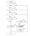
まず、図3(A)は、アイドルストップ制御のために一定時間毎に実行される定期ルーチンを表すフローチャートである。
エンジンECU13のマイコン13aが、図3(A)の定期ルーチンの実行を開始すると、まずS210にて、エコランECU15からのエンジン停止要求があるか否か(つまり、エコランECU15から受信したエンジン停止要求データが“1”であるか否か)を判定し、エンジン停止要求がないと判定した場合には、そのまま当該定期ルーチンを終了するが、エンジン停止要求があると判定した場合には、S220に進む。
First, FIG. 3A is a flowchart showing a regular routine executed at regular intervals for idle stop control.
When the
そして、S220では、エンジン11への燃料噴射を停止してエンジン11を停止させる。
次に、S230にて、クランクセンサ35からのクランク信号が入力されなくなってから(換言すれば、クランク信号が最後に入力されてから)所定時間が経過したか否かを判定し、その所定時間が未だ経過していなければ、次のS240にて、NE同期タスクの実行が許可されているか否かを示す可否フラグを、“許可”を示す方の値(例えば“1”)に設定することで、そのNE同期タスクの実行を許可する。そして、その後、当該定期ルーチンを終了する。
In S220, the fuel injection to the
Next, in S230, it is determined whether or not a predetermined time has elapsed since the crank signal from the
尚、この例でのNE同期タスクとは、クランク信号が入力される毎に起動される図3(B)の割り込み処理(以下、NE割り込み処理という)中で起床される後述のクランクカウンタ更新処理(S340)のタスクである。また、エコランECU15からのエンジン停止要求がない状態において、上記可否フラグは“許可”を示す方の値に設定されている(つまり、NE同期タスクの実行は許可されている)。このため、上記S210でエンジン停止要求がないと判定した場合に、S240へ移行するようにしても良い。また、S230で判定する所定時間は、エンジン11が完全に停止したと考えられる値に設定されている。
The NE synchronization task in this example is a later-described crank counter update process that is woken up in the interrupt process of FIG. 3B (hereinafter referred to as an NE interrupt process) that is started every time a crank signal is input. This is the task of (S340). Further, in a state where there is no engine stop request from the
一方、上記S230にて所定時間が経過したと判定した場合には、S250に移行して、クラッチペダルが踏まれているか否かをクラッチスイッチ27からの信号に基づき判定する。そして、クラッチペダルが踏まれていなければ、S260に進んで、上記可否フラグを、“非許可”を示す方の値(例えば“0”)に設定することにより、NE同期タスクの実行を禁止し、その後、当該定期ルーチンを終了する。
On the other hand, if it is determined in S230 that the predetermined time has elapsed, the process proceeds to S250, and it is determined based on a signal from the
また、上記S250にて、クラッチペダルが踏まれていると判定した場合には、エンジン11の自動停止中に運転者がクラッチペダルを踏んだということであり、エンジン始動条件が成立したと判定して、S240に移行する。そして、そのS240でNE同期タスクの実行を許可した後、当該定期ルーチンを終了する。
If it is determined in S250 that the clutch pedal is depressed, it means that the driver has depressed the clutch pedal during the automatic stop of the
つまり、図3(A)の定期ルーチンでは、エコランECU15からエンジン停止要求があったことを検知すると(S210:YES)、燃料カットによりエンジン11を停止させ(S220)、エンジン11の停止に伴いクランク信号が入力されなくなって所定時間が経過した時に(S230:YES)、クラッチペダルが未だ踏まれていないことを確認した上で(S250:NO)、NE同期タスクの実行を禁止するようにしている(S260)。そして、その後、クラッチペダルが踏まれたことを検知したなら(S250:YES)、NE同期タスクの実行を許可するようにしている(S240)。
That is, in the periodic routine of FIG. 3A, when it is detected that the engine stop request is received from the eco-run ECU 15 (S210: YES), the
次に、図3(B)は、NE割り込み処理を表すフローチャートである。
エンジンECU13のマイコン13aが、NE割り込み処理の実行を開始すると、まずS310にて、NE同期タスクの実行が許可されているか否かを上記可否フラグに基づき判定し、NE同期タスクの実行が許可されていれば(即ち、可否フラグが“許可”を示す値ならば)、S340に移行して、そのNE同期タスクを起床する。そして、NE同期タスクでは、クランクカウンタの値を更新する処理を行う。具体的には、クランクカウンタの値を1つ進める処理を行い、もし、クランクカウンタの値が720°CAに該当する最大値を超えたならば、その値を0に戻す処理も行う。尚、「CA」は、クランク角の略である。そして、S340で起床したNE同期タスクが終了すると、当該NE割り込み処理が終了する。
Next, FIG. 3B is a flowchart showing NE interrupt processing.
When the
また、上記S310にて、NE同期タスクの実行が許可されていない(即ち、可否フラグが“非許可”を示す値であり、NE同期タスクの実行が禁止されている)と判定した場合には、S320に進み、クラッチペダルが踏まれているか否かをクラッチスイッチ27からの信号に基づき判定する。そして、クラッチペダルが踏まれていなければ、NE同期タスクを起床することなく、そのまま当該NE割り込み処理を終了する。
If it is determined in S310 that execution of the NE synchronization task is not permitted (that is, the availability flag is a value indicating “non-permitted” and execution of the NE synchronization task is prohibited). The process proceeds to S320, and it is determined based on the signal from the
一方、上記S320にて、クラッチペダルが踏まれていると判定した場合には、エンジン11の自動停止中に運転者がクラッチペダルを踏んだということであり、エンジン始動条件が成立したと判定して、S330に移行する。そして、S330にて、図3(A)のS240と同様に、上記可否フラグを“許可”を示す方の値に設定することで、NE同期タスクの実行を許可し、その後、S340でNE同期タスクを起床する。そして、そのNE同期タスクが終了すると、当該NE割り込み処理が終了する。
On the other hand, if it is determined in S320 that the clutch pedal is depressed, it means that the driver has depressed the clutch pedal during the automatic stop of the
つまり、図3(B)のNE割り込み処理では、NE同期タスクの実行が許可されている場合には(S310:YES)、そのNE同期タスクを起床してクランクカウンタの値を更新するようになっている(S340)。また、NE同期タスクの実行が禁止されている場合には(S310:NO)、基本的にはNE同期タスクを起床しないが、その回の処理でクラッチペダルが踏まれたことを検知したなら(S320:YES)、NE同期タスクの実行を許可すると共に、その回からNE同期タスクを起床するようにしている(S330,S340)。 That is, in the NE interrupt processing of FIG. 3B, when the NE synchronous task is permitted to be executed (S310: YES), the NE synchronous task is woken up to update the crank counter value. (S340). If execution of the NE synchronization task is prohibited (S310: NO), the NE synchronization task is basically not woken up, but if it is detected that the clutch pedal has been depressed in the processing of that time ( S320: YES), execution of the NE synchronization task is permitted, and the NE synchronization task is woken up from that time (S330, S340).
また、図示は省略しているが、エンジンECU13のマイコン13aは、一定時間毎あるいはクランクカウンタの値が所定値になる毎に起動される別の制御処理にて、クランクカウンタの値を参照すると共に、そのクランクカウンタの値に基づいてインジェクタ39と点火装置への通電を行っている。
Although not shown in the figure, the
次に、以上のようなアイドルストップ制御システムの作用について、図4を用い説明する。
図4における時刻t1以前では、エコランECU15で判定される前述のエンジン停止条件が成立しておらず、エンジン11が作動しており、エンジンECU13では、クランク信号に立ち上がりエッジが生じる毎に、クランクカウンタがカウントアップされる。そのカウントアップは、図3(B)のS340で起床されるNE同期タスクによる。また、エンジンECU13は、クランクカウンタの値に基づいてエンジン11への燃料噴射及び点火を行うことによりエンジン11を作動させている。
Next, the operation of the idle stop control system as described above will be described with reference to FIG.
Before the time t1 in FIG. 4, the engine stop condition determined by the
そして、時刻t1にて、エンジン停止条件が成立したとすると、そのことを検知したエコランECU15からエンジンECU13へ、エンジン停止要求が送信される(S150)。すると、エンジンECU13は、エンジン11への燃料噴射を停止する(S220)。尚、燃料カットが実施されても、エンジン11のクランク軸は惰性で若干回転するため、クランクセンサ35からのクランク信号は、エンジン11が完全に停止するまで出力されることとなる。
If the engine stop condition is satisfied at time t1, an engine stop request is transmitted from the
そして、燃料カットに伴いエンジン11が停止すると、エンジンECU13にクランク信号が入力されなくなるため、クランクカウンタの値は更新されなくなり、エンジン11が停止した時の値のまま保持されることとなる。
When the
また、エンジンECU13では、燃料カットによってクランク信号が入力されなくなってから所定時間が経過すると、NE同期タスク(即ち、クランクカウンタの更新処理)の実行が禁止される(S230:YES→S250:NO→S260)。
The
その後、時刻t2にて、車両の運転者がクラッチペダルを踏み込んだとすると、エコランECU15が、そのことを検知して(S140:YES)、エンジンECU13へのエンジン停止要求を解除すると共に、スタータ29を作動させてエンジン11をクランキングさせる(S170,S180)。すると、再びエンジンECU13にクランク信号が入力され始める。
Thereafter, if the driver of the vehicle depresses the clutch pedal at time t2, the
そして、エンジンECU13においても、図3(A)のS250又は図3(B)のS320の処理により、クラッチペダルが踏まれたこと(即ち、エンジン始動条件の成立)が検知される。そして、NE同期タスクの実行が許可されることとなる(S250:YES→S240、又は、S320:YES→S330)。
Also in the
このため、エンジンECU13では、エンジン11のクランキングによりクランク信号が入力され始めると、クランクカウンタの値が、エンジン停止時の値からカウントアップされていく。そして、クランクカウンタの値が更新されることにより、前述の制御処理による燃料噴射及び点火が再開されて、エンジン11が再始動される。つまり、制御処理では、クランクカウンタの値が予め定められた特定の値になったら、その時点からエンジン回転数等に応じた所定時間後にインジェクタ39や点火装置への通電を開始する、という手順で、燃料噴射や点火を実施するようになっているからである。
For this reason, in the
ここで特に、エンジンECU13では、エコランECU15からのエンジン停止要求を受けてエンジン11を停止させると、その後、エンジン始動条件の成立(本第1実施形態では、クラッチペダルが踏まれたこと)を検知するまでの間、クランクカウンタの更新処理であるNE同期タスクの実行を禁止するようになっている。
Here, in particular, when the
このため、エンジン11のアイドルストップ中において、クランク信号に図4の如くノイズが発生しても、クランクカウンタの値が誤って更新されてしまうことが防止される。
よって、エンジン11の再始動時までクランクカウンタの値を正しい値に保つことができ、エンジン11の再始動時において、誤ったクランク位置に基づいて燃料噴射や点火を実施してしまうことを防止することができる。その結果、アイドルストップ後のエンジン11の再始動性能を常に良好にすることができる。
Therefore, even when noise occurs in the crank signal as shown in FIG. 4 during idling stop of the
Therefore, the value of the crank counter can be kept at a correct value until the
尚、図4における最下段(クランクカウンタの段)において、点線で示されている変化状態は、クランク信号に発生したノイズの立ち上がりエッジによってクランクカウンタの値が更新されてしまった場合を表している。そして、その点線の場合には、エンジン11の再始動時において、クランクカウンタの値が、エンジン停止時の値よりも進んだ値になってしまい、誤ったクランク位置に基づいて燃料噴射や点火を実施してしまうこととなる。これに対して、本実施形態のエンジンECU13によれば、そのような不具合を防止することができるのである。
In the lowermost stage (crank counter stage) in FIG. 4, a change state indicated by a dotted line represents a case where the value of the crank counter has been updated by the rising edge of noise generated in the crank signal. . In the case of the dotted line, when the
また、本実施形態のエンジンECU13では、クランク信号が入力されなくなってから、エンジン11が完全に停止したと考えられる所定時間が経過した時に、エンジン11が停止したと判定して、NE同期タスクの実行を禁止するようになっている。
Further, the
このため、エンジン11が停止する直前にクランク信号の入力間隔が長くなっても、エンジン11が停止したか否かを正確に判断することができ、エンジン11が未だ極低回転で作動している状態でNE同期タスクの実行を禁止してしまいうこと(延いては、クランクカウンタの更新抜けが起こること)を確実に回避することができる。
For this reason, even if the input interval of the crank signal becomes long immediately before the
また、本実施形態では、クラッチペダルが踏まれたことが、エンジン始動条件になっているが、エンジンECU13は、そのエンジン始動条件の成立/非成立をクラッチスイッチ27からの信号に基づき判定しているため、エコランECU15がエンジン始動条件の成立を検知するのとほぼ同時に、エンジン始動条件の成立を検知することができる。このため、エンジン11の再始動時において、NE同期タスクの実行禁止を解除するタイミングが遅れてクランクカウンタの更新抜けが起こってしまうことを確実に回避することができる。
In this embodiment, the engine start condition is that the clutch pedal is depressed, but the
更に、エンジンECU13のマイコン13aは、図3(A)の定期ルーチンと、図3(B)のNE割り込み処理との両方で、エンジン始動条件が成立したか否かを判定するようになっているため、定期ルーチンのみで判定する場合と比べて、エンジン始動条件が成立したことを早期に検知できる可能性を高めることができる。よって、NE同期タスクの実行禁止を解除するタイミングが遅れることを一層確実に回避することができる。
Further, the
また、エンジンECU13において、クランクカウンタの更新処理であるNE同期タスクは、NE割り込み処理の中で起床されて実行されるようになっていると共に、そのNE割り込み処理のプログラムは、上記可否フラグが“非許可”を示す方の値に設定されている場合には、NE同期タスクが起床されずにスキップされるようになっている。そして、図3(A)の定期ルーチンでは、可否フラグを、“非許可”を示す方の値に設定することで、NE同期タスクの実行を禁止するようになっている。
In the
このため、クランクカウンタの更新処理が行われるのを禁止するためにNE割り込み処理自体を禁止する構成と比べると、信頼性が高いという利点がある。その理由は、請求項10の発明について述べた理由の通りである。 For this reason, there is an advantage that the reliability is high as compared with the configuration in which the NE interrupt processing itself is prohibited in order to prohibit the update processing of the crank counter. The reason is the same as the reason described for the invention of claim 10.
尚、上記実施形態では、エコランECU15がアイドルストップ制御手段に相当している。また、クランクセンサ35が回転センサに相当し、クランク信号が回転信号に相当している。そして、定期ルーチンにおけるS230〜S260の処理とNE割り込み処理におけるS310〜S330の処理が更新禁止手段に相当している。
[第2実施形態]
第2実施形態のアイドルストップ制御システムは、第1実施形態と比較すると、下記の点が異なっている。尚、構成要素の符号は、第1実施形態と同じものを用いる。
In the above embodiment, the
[Second Embodiment]
The idle stop control system of the second embodiment is different from the first embodiment in the following points. In addition, the code | symbol of a component uses the same thing as 1st Embodiment.
まず、車両は、変速機として自動変速機を搭載した車両であって、クラッチペダルの無い車両である。また、エコランECU15とエンジンECU13には、ニュートラルスイッチ25及びクラッチスイッチ27に代えて、車両のブレーキペダルが踏まれるとオンするブレーキスイッチ(図示省略)からの信号が入力されている。
First, the vehicle is a vehicle equipped with an automatic transmission as a transmission and has no clutch pedal. Further, the
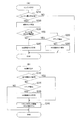
そして、エコランECU15のマイコン15aは、図2の処理に代えて、図5の処理を行う。
図5の処理では、図2の処理と比較すると、S130の代わりにS135の判定が行われ、S140の代わりにS145の判定が行われる点が異なっている。
Then, the
The process of FIG. 5 differs from the process of FIG. 2 in that the determination of S135 is performed instead of S130, and the determination of S145 is performed instead of S140.
即ち、S135では、車速が0でアクセルペダルが踏まれていない状態になってから所定時間が経過したか否かを判定し、所定時間が経過していなければ、そのまま当該図5の処理を終了するが、所定時間が経過したならば、S145に進む。 That is, in S135, it is determined whether or not a predetermined time has elapsed since the vehicle speed is 0 and the accelerator pedal is not depressed. If the predetermined time has not elapsed, the processing of FIG. However, if the predetermined time has elapsed, the process proceeds to S145.
そして、S145では、ブレーキペダルが踏まれていない(ブレーキ=オフ)か否かを上記ブレーキスイッチからの信号に基づき判定し、ブレーキペダルが踏まれていれば、S150に進んで、エンジンECU13へエンジン停止要求を送信し、ブレーキペダルが踏まれていなければ、前述のS160に移行する。
In S145, it is determined whether or not the brake pedal is not depressed (brake = off) based on the signal from the brake switch. If the brake pedal is depressed, the process proceeds to S150 and the
つまり、エコランECU15は、車速が0でアクセルペダルが踏まれていない状態になってから所定時間が経過しており、且つ、ブレーキペダルが踏まれていれば、エンジン停止条件が成立したと判断して、エンジンECU13へエンジン停止要求を送信するようになっている。そして、エコランECU15は、エンジンECU13へエンジン停止要求を送信することによりエンジン11を停止させた後、運転者がブレーキペダルを踏むのを止めたことを検知すると(S145及びS160:YES)、エンジンを再始動すべきエンジン始動条件が成立したと判定して、エンジンECU13へのエンジン停止要求を解除すると共に、スタータ29を作動させるようになっている(S170,S180)。運転者がブレーキペダルから足を放したということは、走行再開を意図していると考えられるからである。
In other words, the
このため、エンジンECU13のマイコン13aは、図3(A)の定期ルーチンに代えて、図6(A)の定期ルーチンを行うと共に、図3(B)のNE割り込み処理に代えて、図6(B)のNE割り込み処理を行う。
For this reason, the
そして、図6(A)の定期ルーチンでは、図3(A)のS250に代わるS253にて、ブレーキペダルが踏まれていないか否かをブレーキスイッチからの信号に基づき判定し、ブレーキペダルが踏まれていれば、S260に進んでNE同期タスクの実行を禁止するが、ブレーキペダルが踏まれていなければ、エンジン11の自動停止中に運転者がブレーキペダルを踏むのを止めたということであり、エンジン始動条件が成立したと判定してS240に移行し、NE同期タスクの実行を許可する。
In the regular routine of FIG. 6A, whether or not the brake pedal is depressed is determined based on the signal from the brake switch in S253 instead of S250 of FIG. 3A, and the brake pedal is depressed. If it is rare, the process proceeds to S260 and execution of the NE synchronization task is prohibited, but if the brake pedal is not depressed, the driver has stopped stepping on the brake pedal while the
また同様に、図6(B)のNE割り込み処理では、図3(B)のS320に代わるS323にて、ブレーキペダルが踏まれていないか否かをブレーキスイッチからの信号に基づき判定し、ブレーキペダルが踏まれていれば、そのまま当該NE割り込み処理を終了するが、ブレーキペダルが踏まれていなければ、エンジン始動条件が成立したと判定してS330に進み、NE同期タスクの実行を許可した後、次のS340にてNE同期タスクを起床する。 Similarly, in the NE interrupt process of FIG. 6B, whether or not the brake pedal is depressed is determined based on the signal from the brake switch in S323 instead of S320 of FIG. If the pedal is depressed, the NE interruption process is terminated as it is. However, if the brake pedal is not depressed, it is determined that the engine start condition is satisfied, and the process proceeds to S330, after the execution of the NE synchronization task is permitted. In step S340, the NE synchronization task is awakened.
つまり、第2実施形態では、運転者がブレーキペダルを踏むのを止めたこと(ブレーキ=オフ)が、エンジン始動条件になっているため、エンジンECU13は、そのことを検知して、NE同期タスクの実行禁止状態から実行許可状態に切り替えるようになっている。
That is, in the second embodiment, since the engine start condition is that the driver has stopped stepping on the brake pedal (brake = off), the
そして、このような第2実施形態のECU13によっても、第1実施形態と同じ効果が得られる。特に、本第2実施形態においても、エンジンECU13は、エンジン始動条件の成立/非成立を、エコランECU15と同じくブレーキスイッチからの信号に基づき判定しているため、エコランECU15がエンジン始動条件の成立を検知するのとほぼ同時に、エンジン始動条件の成立を検知することができる。このため、エンジン11の再始動時において、NE同期タスクの実行禁止を解除するタイミングが遅れてクランクカウンタの更新抜けが起こってしまうことを確実に回避することができる。
[第3実施形態]
第3実施形態のアイドルストップ制御システムは、第1実施形態と比較すると、下記の点が異なっている。尚、構成要素の符号は、第1実施形態と同じものを用いる。
And also by ECU13 of such 2nd Embodiment, the same effect as 1st Embodiment is acquired. In particular, also in the second embodiment, the
[Third Embodiment]
The idle stop control system of the third embodiment is different from the first embodiment in the following points. In addition, the code | symbol of a component uses the same thing as 1st Embodiment.
まず、エンジンECU13には、クラッチスイッチ27に代えて、クラッチペダルの踏み込み量に応じて出力値が変化するクラッチストロークセンサ(図示省略)からの信号が入力されている。尚、図8に示すように、本実施形態におけるクラッチストロークセンサは、クラッチペダルの踏み込み量(クラッチストローク)が大きくなるほど、出力電圧が低下するタイプのセンサである。
First, instead of the
そして、エンジンECU13のマイコン13aは、図3(A)の定期ルーチンに代えて、図7(A)の定期ルーチンを行うと共に、図3(B)のNE割り込み処理に代えて、図7(B)のNE割り込み処理を行う。
Then, the
そして、図7(A)の定期ルーチンでは、図3(A)のS250に代わるS255にて、クラッチペダルが踏まれているか否かをクラッチストロークセンサからの信号に基づき判定する。具体的には、クラッチストロークセンサの出力電圧(センサ電圧)が、クラッチペダルが踏まれたと考えられる半クラッチ状態の所定値VL(図8参照)よりも低ければ、クラッチペダルが踏まれていると判定する。 In the regular routine in FIG. 7A, it is determined in S255 instead of S250 in FIG. 3A whether or not the clutch pedal is depressed based on a signal from the clutch stroke sensor. Specifically, if the output voltage (sensor voltage) of the clutch stroke sensor is lower than a predetermined value VL (see FIG. 8) in a half-clutch state where the clutch pedal is considered to be depressed, the clutch pedal is depressed. judge.
同様に、図7(B)のNE割り込み処理では、図3(B)のS320に代わるS325にて、クラッチペダルが踏まれているか否かをクラッチストロークセンサからの信号に基づき判定する。 Similarly, in the NE interrupt process of FIG. 7B, whether or not the clutch pedal is depressed is determined based on a signal from the clutch stroke sensor in S325 instead of S320 of FIG. 3B.
このような第3実施形態のエンジンECU13によれば、クラッチペダルが踏まれたことを、半クラッチ状態の段階で検知することができる。よって、第1実施形態よりも、エンジン始動条件の検知タイミングが早くなり、NE同期タスクの禁止解除タイミングを一層早くすることができる。
According to the
尚、エコランECU15にもクラッチストロークセンサからの信号を入力し、図2の処理におけるS140では、図7のS255,S325と同様の判定を行うようにしても良い。また、クラッチストロークセンサは、クラッチストロークが大きくなるほど出力電圧が大きくなるタイプのものでも良い。
[第4実施形態]
第4実施形態のアイドルストップ制御システムは、第1〜第3実施形態と比較すると、下記の点が異なっている。尚、構成要素の符号は、第1実施形態と同じものを用いる。
The
[Fourth Embodiment]
The idle stop control system of the fourth embodiment differs from the first to third embodiments in the following points. In addition, the code | symbol of a component uses the same thing as 1st Embodiment.
第4実施形態において、エンジンECU13のマイコン13aは、定期ルーチンとして図9(A)の定期ルーチンを行うと共に、NE割り込み処理として図9(B)のNE割り込み処理を行う。
In the fourth embodiment, the
そして、図9(A)の定期ルーチンでは、図3(A),図6(A),図7(A)の定期ルーチンと比較すると、S210でエンジン停止要求がないと判定した場合に、S240へ移行するようになっている。 In the regular routine of FIG. 9A, when it is determined in S210 that there is no engine stop request as compared with the regular routines of FIG. 3A, FIG. 6A, and FIG. It has come to move to.
更に、図9(A)の定期ルーチンでは、図3(A)のS250又は図6(A)のS253又は図7(A)のS255に代わるS257にて、エコランECU15からのエンジン停止要求が解除されたか否か(換言すれば、エンジン始動要求を受けたか否かであり、詳しくは、エコランECU15からのエンジン停止要求データが“1”から“0”に変わったか否か)を判定する。そして、エンジン停止要求が解除されていなければ、S260に進んでNE同期タスクの実行を禁止するが、エンジン停止要求が解除されたならば(エンジン始動要求を受けたならば)、エンジン始動条件が成立したと判定してS240に移行し、NE同期タスクの実行を許可する。
Further, in the periodic routine of FIG. 9A, the engine stop request from the
同様に、図9(B)のNE割り込み処理では、図3(B)のS320又は図6(B)のS323又は図7(B)のS325に代わるS327にて、エコランECU15からのエンジン停止要求が解除されたか否かを判定する。そして、エンジン停止要求が解除されていなければ、そのまま当該NE割り込み処理を終了するが、エンジン停止要求が解除されたならば(エンジン始動要求を受けたならば)、エンジン始動条件が成立したと判定してS330に移行し、NE同期タスクの実行を許可した上で、NE同期タスクを起床する(S340)。
Similarly, in the NE interrupt process of FIG. 9B, an engine stop request from the
つまり、第4実施形態のエンジンECU13では、エンジン始動条件が成立したか否かを、エコランECU15からのエンジン始動要求を受けたか否かで判断するようにしている。そして、この構成によれば、エンジン始動条件が成立したか否かを判定するために、そのためのスイッチ信号やセンサ信号(具体的には、クラッチスイッチ27や、ブレーキスイッチや、クラッチストロークセンサからの信号)をエンジンECU13へ別途入力させる必要が無いという点で有利である。
That is, the
尚、エコランECU15は、エンジン始動要求の送信を行ってから、スタータ29を作動させるため(S170,S180)、エンジンECU13とエコランECU15との間の通信遅れが小さければ、エンジンECU13にて、エンジン11のクランキングに伴うクランク信号の1つ目の入力タイミングよりも前か、その1つ目の入力タイミングにて、NE同期タスクの実行を許可することができる(つまり、クランクカウンタの更新抜けが起こることはない)。
The
また、両ECU13,15間の通信遅れが大きくて、第4実施形態の構成では、エンジン11のクランキングに伴うクランク信号の1つ目が入力された際に、NE同期タスクの実行許可が間に合わないのであれば、第1〜第3実施形態の構成を採用すれば良い。
Further, the communication delay between the
以上、本発明の一実施形態について説明したが、本発明はこうした実施形態に何等限定されるものではなく、本発明の要旨を逸脱しない範囲において、種々なる態様で実施し得ることは勿論である。 As mentioned above, although one Embodiment of this invention was described, this invention is not limited to such Embodiment at all, Of course, in the range which does not deviate from the summary of this invention, it can implement in a various aspect. .
例えば、上記実施形態では、エンジンECU13とエコランECU15とが別体であったが、エンジンECU13の中に、エコランECU15の機能を実現する回路が内蔵されている構成でも良い。
For example, in the above embodiment, the
また、クラッチスイッチ27は、クラッチペダルが踏み込まれるとオフするタイプのものでも良く、同様に、ブレーキスイッチは、ブレーキペダルが踏み込まれるとオフするタイプのものでも良い。
The
また、カムセンサからのカム信号に基づいてクランクカウンタの更新を行う構成であっても、本発明は適用することができる。
また、制御対象のエンジンは、ディーゼルエンジンであっても良い。
Further, the present invention can be applied to a configuration in which the crank counter is updated based on the cam signal from the cam sensor.
Further, the engine to be controlled may be a diesel engine.
また、エンジン停止条件とエンジン始動条件は、前述した実施形態の条件に限るものではない。 Further, the engine stop condition and the engine start condition are not limited to the conditions of the above-described embodiment.
11…エンジン、13…エンジンECU、15…エコランECU、13a,15a…マイコン、21…車速センサ、23…アクセルスイッチ、25…ニュートラルスイッチ、27…クラッチスイッチ、29…スタータ、31…スタータリレー、33…車載バッテリ、35…クランクセンサ、35…通信線、37…カムセンサ、39…インジェクタ
DESCRIPTION OF
Claims (10)
前記エンジンのクランク軸の回転に応じて回転センサから出力される回転信号に基づいて、前記クランク軸の2回転中における該クランク軸の回転位置であるクランク位置を示すクランクカウンタの値を更新するクランクカウンタ更新処理を行うと共に、前記クランクカウンタの値に基づいて、前記クランク位置を把握して前記エンジンへの燃料噴射と点火を実施し、
更に、前記アイドルストップ制御手段からの前記エンジン停止要求を受けると、前記エンジンへの燃料噴射を停止して該エンジンを停止させ、その後、前記アイドルストップ制御手段により前記エンジンがクランキングされると、前記エンジンへの燃料噴射と点火を再開して該エンジンを再始動させるエンジン制御装置であって、
前記エンジン停止要求によって前記エンジンが停止すると、その後、前記エンジン始動条件が成立したと判定するまでの間、前記クランクカウンタ更新処理が行われるのを禁止する更新禁止手段を備えていること、
を特徴とするエンジン制御装置。 When it is determined that the engine stop condition is satisfied, an engine stop request is issued.After that, when it is determined that the engine start condition is satisfied, the engine is mounted on the vehicle together with an idle stop control means for cranking the engine to start the engine,
A crank that updates a value of a crank counter indicating a crank position that is a rotational position of the crankshaft during two rotations of the crankshaft based on a rotation signal output from a rotation sensor in accordance with the rotation of the crankshaft of the engine While performing a counter update process, based on the value of the crank counter, grasping the crank position and performing fuel injection and ignition to the engine ,
Further, upon receiving the engine stop request from the idle stop control means, the fuel injection to the engine is stopped to stop the engine, and then the engine is cranked by the idle stop control means. An engine control device that restarts fuel injection and ignition to the engine and restarts the engine,
An update prohibiting means for prohibiting the crank counter update process from being performed until the engine start condition is determined to be satisfied after the engine is stopped by the engine stop request;
An engine control device.
前記更新禁止手段は、前記回転信号が入力されなくなってから所定時間が経過した時に、前記エンジンが停止したと判定して、前記クランクカウンタ更新処理が行われるのを禁止すること、
を特徴とするエンジン制御装置。 The engine control device according to claim 1,
The update prohibiting means determines that the engine has stopped when a predetermined time has elapsed since the rotation signal is not input, and prohibits the crank counter updating process from being performed;
An engine control device.
前記車両は、変速機として手動変速機を搭載した車両であり、
前記エンジン始動条件は、車両の運転者が前記手動変速機のクラッチペダルを踏んだという条件であること、
を特徴とするエンジン制御装置。 The engine control device according to claim 1 or 2,
The vehicle is a vehicle equipped with a manual transmission as a transmission,
The engine start condition is a condition that a vehicle driver has stepped on a clutch pedal of the manual transmission,
An engine control device.
前記エンジン始動条件は、車両の運転者がブレーキペダルを踏むのを止めたという条件であること、
を特徴とするエンジン制御装置。 The engine control device according to claim 1 or 2,
The engine start condition is a condition that the driver of the vehicle has stopped pressing the brake pedal,
An engine control device.
前記更新禁止手段は、前記クラッチペダルが踏み込まれるとオン/オフの状態が切り替わるクラッチスイッチからの信号に基づいて、前記エンジン始動条件が成立したか否かを判定すること、
を特徴とするエンジン制御装置。 The engine control apparatus according to claim 3, wherein
The update prohibiting means determines whether or not the engine start condition is satisfied based on a signal from a clutch switch that is switched on / off when the clutch pedal is depressed;
An engine control device.
前記更新禁止手段は、前記クラッチペダルの踏み込み量に応じて出力値が変化するクラッチストロークセンサからの信号に基づいて、前記エンジン始動条件が成立したか否かを判定すること、
を特徴とするエンジン制御装置。 The engine control apparatus according to claim 3, wherein
The update prohibiting means determines whether or not the engine start condition is satisfied based on a signal from a clutch stroke sensor whose output value changes according to the depression amount of the clutch pedal.
An engine control device.
前記更新禁止手段は、前記ブレーキペダルが踏まれるとオン/オフの状態が切り替わるブレーキスイッチからの信号に基づいて、前記エンジン始動条件が成立したか否かを判定すること、
を特徴とするエンジン制御装置。 The engine control apparatus according to claim 4, wherein
The update prohibiting means determines whether or not the engine start condition is satisfied based on a signal from a brake switch that switches on / off when the brake pedal is depressed;
An engine control device.
前記アイドルストップ制御手段は、エンジン始動条件が成立したと判定すると、エンジン始動要求を出力するようになっており、
前記更新禁止手段は、前記アイドルストップ制御手段からのエンジン始動要求を受けると、前記エンジン始動条件が成立したと判定して、前記クランクカウンタ更新処理が行われるのを許可すること、
を特徴とするエンジン制御装置。 The engine control device according to any one of claims 1 to 4,
When it is determined that the engine start condition is satisfied, the idle stop control means outputs an engine start request,
The update prohibiting means, upon receiving an engine start request from the idle stop control means, determines that the engine start condition is satisfied and permits the crank counter update process to be performed.
An engine control device.
前記更新禁止手段はマイコンにより実現されており、そのマイコンは、一定時間毎に起動される定期ルーチンと、前記回転信号が入力される毎に起動される割り込み処理との両方で、前記エンジン始動条件が成立したか否かを判定すること、
を特徴とするエンジン制御装置。 The engine control device according to any one of claims 1 to 8,
The update prohibiting means is realized by a microcomputer, and the microcomputer has the engine start condition both in a periodic routine that is activated every predetermined time and in an interrupt process that is activated every time the rotation signal is input. Determining whether or not
An engine control device.
前記クランクカウンタ更新処理は、前記回転信号が入力される毎に起動される割り込み処理の中で行われるようになっていると共に、
前記割り込み処理のプログラムは、前記クランクカウンタ更新処理の実行が許可されているか否かを示す可否情報が、非許可を示す内容に設定されている場合には、前記クランクカウンタ更新処理がスキップされるようになっており、
前記更新禁止手段は、前記可否情報を非許可を示す内容に設定することで、前記クランクカウンタ更新処理が行われるのを禁止すること、
を特徴とするエンジン制御装置。 The engine control device according to any one of claims 1 to 9,
The crank counter update process is performed in an interrupt process activated every time the rotation signal is input,
The interrupt processing program skips the crank counter update process when the permission information indicating whether or not the execution of the crank counter update process is permitted is set to a content indicating non-permission. And
The update prohibiting means prohibits the crank counter update process from being performed by setting the permission information to a content indicating non-permission.
An engine control device.
Priority Applications (3)
| Application Number | Priority Date | Filing Date | Title |
|---|---|---|---|
| JP2007293372A JP4466720B2 (en) | 2007-11-12 | 2007-11-12 | Engine control device |
| EP08019684.3A EP2058497B1 (en) | 2007-11-12 | 2008-11-11 | Apparatus for controlling operation of engine mounted on vehicle provided with idle stop function |
| US12/269,071 US7797099B2 (en) | 2007-11-12 | 2008-11-12 | Apparatus for controlling operation of engine mounted on vehicle provided with idle stop function |
Applications Claiming Priority (1)
| Application Number | Priority Date | Filing Date | Title |
|---|---|---|---|
| JP2007293372A JP4466720B2 (en) | 2007-11-12 | 2007-11-12 | Engine control device |
Publications (2)
| Publication Number | Publication Date |
|---|---|
| JP2009121250A JP2009121250A (en) | 2009-06-04 |
| JP4466720B2 true JP4466720B2 (en) | 2010-05-26 |
Family
ID=40298703
Family Applications (1)
| Application Number | Title | Priority Date | Filing Date |
|---|---|---|---|
| JP2007293372A Active JP4466720B2 (en) | 2007-11-12 | 2007-11-12 | Engine control device |
Country Status (3)
| Country | Link |
|---|---|
| US (1) | US7797099B2 (en) |
| EP (1) | EP2058497B1 (en) |
| JP (1) | JP4466720B2 (en) |
Families Citing this family (27)
| Publication number | Priority date | Publication date | Assignee | Title |
|---|---|---|---|---|
| JP4987551B2 (en) * | 2007-04-19 | 2012-07-25 | 富士通テン株式会社 | Eco-run system, control program, and eco-run status notification device |
| DE102008060350A1 (en) * | 2008-12-03 | 2010-06-10 | Bayerische Motoren Werke Aktiengesellschaft | Method for automatically switching off an internal combustion engine |
| DE102008061790A1 (en) * | 2008-12-11 | 2010-07-08 | Bayerische Motoren Werke Aktiengesellschaft | Method for automatically switching off and starting an internal combustion engine |
| JP4811474B2 (en) * | 2009-02-25 | 2011-11-09 | 株式会社デンソー | Engine automatic stop and start system |
| KR101163182B1 (en) * | 2009-02-27 | 2012-07-06 | 가부시키가이샤 덴소 | System for restarting internal combustion engine when engine restart condition is met |
| JP5381747B2 (en) * | 2010-01-26 | 2014-01-08 | 株式会社デンソー | Fuel injection device |
| JP5165705B2 (en) * | 2010-01-28 | 2013-03-21 | 日立オートモティブシステムズ株式会社 | Control device for internal combustion engine |
| JP5470241B2 (en) * | 2010-12-28 | 2014-04-16 | 日立オートモティブシステムズ株式会社 | Vehicle control device |
| RU2533365C1 (en) * | 2011-03-08 | 2014-11-20 | Тойота Дзидося Кабусики Кайся | Device and method for engine control, starter and vehicle |
| DE112012001585T5 (en) | 2011-04-07 | 2014-01-16 | Remy Technologies Llc. | Starter machine system and method |
| WO2012139123A2 (en) | 2011-04-07 | 2012-10-11 | Remy Technologies, Llc | Starter machine system and method |
| JP5879743B2 (en) * | 2011-05-16 | 2016-03-08 | 日産自動車株式会社 | Engine automatic stop / restart device |
| DE102011111226A1 (en) * | 2011-08-20 | 2013-02-21 | GM Global Technology Operations LLC (n. d. Gesetzen des Staates Delaware) | Method of operating an engine |
| JP5293895B1 (en) * | 2011-09-12 | 2013-09-18 | トヨタ自動車株式会社 | Vehicle control device |
| WO2013076786A1 (en) * | 2011-11-21 | 2013-05-30 | トヨタ自動車 株式会社 | Internal combustion engine control device |
| JP5790479B2 (en) * | 2011-12-16 | 2015-10-07 | トヨタ自動車株式会社 | Control device for internal combustion engine |
| JP5442042B2 (en) * | 2012-01-18 | 2014-03-12 | 三菱電機株式会社 | Engine starting device and engine starting method |
| US8860235B2 (en) | 2012-02-24 | 2014-10-14 | Remy Technologies, Llc | Starter machine system and method |
| US8872369B2 (en) | 2012-02-24 | 2014-10-28 | Remy Technologies, Llc | Starter machine system and method |
| US8829845B2 (en) * | 2012-02-28 | 2014-09-09 | Remy Technologies, Llc | Starter machine system and method |
| US8733190B2 (en) | 2012-04-25 | 2014-05-27 | Remy Technologies, Llc | Starter machine system and method |
| US9020659B2 (en) * | 2012-06-15 | 2015-04-28 | Ford Global Technologies, Llc | Dynamometer vehicle operating mode control |
| DE102012217289A1 (en) * | 2012-09-25 | 2014-03-27 | Ford Global Technologies, Llc | Method and device for operating an automatic start / stop system |
| US9102334B2 (en) | 2012-10-29 | 2015-08-11 | Deere & Company | Methods and apparatus to control motors |
| CN105882603A (en) * | 2015-10-30 | 2016-08-24 | 乐卡汽车智能科技(北京)有限公司 | Information processing method and system |
| KR102463459B1 (en) | 2017-12-27 | 2022-11-04 | 현대자동차주식회사 | Method for Improving Engine Start Performance of Vehicle |
| US10385815B1 (en) | 2018-03-05 | 2019-08-20 | Ford Global Technologies, Llc | Methods and system for operating an engine |
Family Cites Families (11)
| Publication number | Priority date | Publication date | Assignee | Title |
|---|---|---|---|---|
| JP3815096B2 (en) * | 1998-12-28 | 2006-08-30 | 日産自動車株式会社 | Brake operation detection method for idle stop system |
| JP3887979B2 (en) * | 1999-01-12 | 2007-02-28 | 株式会社デンソー | Information processing apparatus and engine control apparatus |
| JP3597718B2 (en) * | 1999-01-26 | 2004-12-08 | 三菱電機株式会社 | Cylinder identification device for internal combustion engine |
| JP3503593B2 (en) | 2000-01-20 | 2004-03-08 | 株式会社デンソー | Engine control device |
| JP2002266674A (en) | 2001-03-09 | 2002-09-18 | Denso Corp | Automatic starting and stopping device for internal combustion engine |
| JP3633531B2 (en) * | 2001-08-28 | 2005-03-30 | トヨタ自動車株式会社 | Internal combustion engine stop / start control device |
| US7142973B2 (en) * | 2004-06-11 | 2006-11-28 | Denso Corporation | Engine control apparatus designed to ensure accuracy in determining engine position |
| JP4424188B2 (en) * | 2004-12-10 | 2010-03-03 | トヨタ自動車株式会社 | Control device for internal combustion engine |
| JP4276190B2 (en) * | 2005-02-07 | 2009-06-10 | 株式会社日立製作所 | Control device for internal combustion engine |
| FR2890690B1 (en) * | 2005-09-09 | 2007-11-09 | Siemens Vdo Automotive Sas | METHOD FOR DETERMINING INVERSION OF DIRECTION OF ROTATION OF MOTOR |
| JP4187013B2 (en) * | 2006-06-06 | 2008-11-26 | 国産電機株式会社 | Ignition device for internal combustion engine |
-
2007
- 2007-11-12 JP JP2007293372A patent/JP4466720B2/en active Active
-
2008
- 2008-11-11 EP EP08019684.3A patent/EP2058497B1/en active Active
- 2008-11-12 US US12/269,071 patent/US7797099B2/en active Active
Also Published As
| Publication number | Publication date |
|---|---|
| EP2058497A2 (en) | 2009-05-13 |
| US7797099B2 (en) | 2010-09-14 |
| JP2009121250A (en) | 2009-06-04 |
| EP2058497A3 (en) | 2011-06-01 |
| US20090138184A1 (en) | 2009-05-28 |
| EP2058497B1 (en) | 2016-02-10 |
Similar Documents
| Publication | Publication Date | Title |
|---|---|---|
| JP4466720B2 (en) | Engine control device | |
| JP4144348B2 (en) | Engine start system | |
| JP4926272B1 (en) | Engine automatic stop / restart device | |
| US8688359B2 (en) | Idle stop control method and control device | |
| JP5214006B2 (en) | ENGINE CONTROL DEVICE AND ENGINE CONTROL METHOD | |
| JP5167237B2 (en) | Rotation sensor abnormality determination device | |
| JP2010229882A (en) | Vehicle control device and idling stop system | |
| US20110172900A1 (en) | Controller for Idle Stop System | |
| US20140345556A1 (en) | Device for automatically stopping and restarting internal combustion engine | |
| JP2013189879A (en) | Engine control apparatus | |
| JP5255712B1 (en) | Engine automatic stop / restart device | |
| US9188070B2 (en) | Vehicle stop control system | |
| JP5187467B2 (en) | ENGINE CONTROL DEVICE AND CONTROL METHOD, ENGINE START DEVICE, AND VEHICLE | |
| JP5477239B2 (en) | Engine stop / start control device | |
| CN109653888B (en) | Control device and control method for internal combustion engine | |
| US20160115931A1 (en) | Engine automatic stop/restart device | |
| JP3567834B2 (en) | Engine control device | |
| JP5951115B2 (en) | Engine automatic stop / restart device and engine automatic stop / restart method | |
| US20110136623A1 (en) | Method for positioning an engine | |
| JP2002349314A (en) | Engine automatic stop device | |
| EP2006519B1 (en) | Controller for a vehicle | |
| JP6828391B2 (en) | Engine restart device | |
| JP2009052410A (en) | Control device for on-vehicle internal combustion engine | |
| JP5907021B2 (en) | Engine start control device | |
| JP2017145743A (en) | Internal combustion engine control device |
Legal Events
| Date | Code | Title | Description |
|---|---|---|---|
| A621 | Written request for application examination |
Free format text: JAPANESE INTERMEDIATE CODE: A621 Effective date: 20090408 |
|
| A977 | Report on retrieval |
Free format text: JAPANESE INTERMEDIATE CODE: A971007 Effective date: 20091030 |
|
| A131 | Notification of reasons for refusal |
Free format text: JAPANESE INTERMEDIATE CODE: A131 Effective date: 20091110 |
|
| A521 | Request for written amendment filed |
Free format text: JAPANESE INTERMEDIATE CODE: A523 Effective date: 20091222 |
|
| TRDD | Decision of grant or rejection written | ||
| A01 | Written decision to grant a patent or to grant a registration (utility model) |
Free format text: JAPANESE INTERMEDIATE CODE: A01 Effective date: 20100202 |
|
| A01 | Written decision to grant a patent or to grant a registration (utility model) |
Free format text: JAPANESE INTERMEDIATE CODE: A01 |
|
| A61 | First payment of annual fees (during grant procedure) |
Free format text: JAPANESE INTERMEDIATE CODE: A61 Effective date: 20100215 |
|
| R151 | Written notification of patent or utility model registration |
Ref document number: 4466720 Country of ref document: JP Free format text: JAPANESE INTERMEDIATE CODE: R151 |
|
| FPAY | Renewal fee payment (event date is renewal date of database) |
Free format text: PAYMENT UNTIL: 20130305 Year of fee payment: 3 |
|
| FPAY | Renewal fee payment (event date is renewal date of database) |
Free format text: PAYMENT UNTIL: 20140305 Year of fee payment: 4 |
|
| R250 | Receipt of annual fees |
Free format text: JAPANESE INTERMEDIATE CODE: R250 |
|
| R250 | Receipt of annual fees |
Free format text: JAPANESE INTERMEDIATE CODE: R250 |
|
| R250 | Receipt of annual fees |
Free format text: JAPANESE INTERMEDIATE CODE: R250 |
|
| R250 | Receipt of annual fees |
Free format text: JAPANESE INTERMEDIATE CODE: R250 |
|
| R250 | Receipt of annual fees |
Free format text: JAPANESE INTERMEDIATE CODE: R250 |
|
| R250 | Receipt of annual fees |
Free format text: JAPANESE INTERMEDIATE CODE: R250 |
|
| R250 | Receipt of annual fees |
Free format text: JAPANESE INTERMEDIATE CODE: R250 |
|
| R250 | Receipt of annual fees |
Free format text: JAPANESE INTERMEDIATE CODE: R250 |
|
| R250 | Receipt of annual fees |
Free format text: JAPANESE INTERMEDIATE CODE: R250 |
|
| R250 | Receipt of annual fees |
Free format text: JAPANESE INTERMEDIATE CODE: R250 |