JP4459446B2 - Tampon with flexible panel - Google Patents
Tampon with flexible panel Download PDFInfo
- Publication number
- JP4459446B2 JP4459446B2 JP2000561927A JP2000561927A JP4459446B2 JP 4459446 B2 JP4459446 B2 JP 4459446B2 JP 2000561927 A JP2000561927 A JP 2000561927A JP 2000561927 A JP2000561927 A JP 2000561927A JP 4459446 B2 JP4459446 B2 JP 4459446B2
- Authority
- JP
- Japan
- Prior art keywords
- tampon
- flexible panel
- absorbent core
- flexible
- cord
- Prior art date
- Legal status (The legal status is an assumption and is not a legal conclusion. Google has not performed a legal analysis and makes no representation as to the accuracy of the status listed.)
- Expired - Fee Related
Links
- AWYMFBJJKFTCFO-PKPIPKONSA-N C(C1)[C@H]2C1CCC2 Chemical compound C(C1)[C@H]2C1CCC2 AWYMFBJJKFTCFO-PKPIPKONSA-N 0.000 description 1
Images


Classifications
-
- A—HUMAN NECESSITIES
- A61—MEDICAL OR VETERINARY SCIENCE; HYGIENE
- A61F—FILTERS IMPLANTABLE INTO BLOOD VESSELS; PROSTHESES; DEVICES PROVIDING PATENCY TO, OR PREVENTING COLLAPSING OF, TUBULAR STRUCTURES OF THE BODY, e.g. STENTS; ORTHOPAEDIC, NURSING OR CONTRACEPTIVE DEVICES; FOMENTATION; TREATMENT OR PROTECTION OF EYES OR EARS; BANDAGES, DRESSINGS OR ABSORBENT PADS; FIRST-AID KITS
- A61F13/00—Bandages or dressings; Absorbent pads
- A61F13/15—Absorbent pads, e.g. sanitary towels, swabs or tampons for external or internal application to the body; Supporting or fastening means therefor; Tampon applicators
- A61F13/20—Tampons, e.g. catamenial tampons; Accessories therefor
- A61F13/2051—Tampons, e.g. catamenial tampons; Accessories therefor characterised by the material or the structure of the inner absorbing core
-
- A—HUMAN NECESSITIES
- A61—MEDICAL OR VETERINARY SCIENCE; HYGIENE
- A61F—FILTERS IMPLANTABLE INTO BLOOD VESSELS; PROSTHESES; DEVICES PROVIDING PATENCY TO, OR PREVENTING COLLAPSING OF, TUBULAR STRUCTURES OF THE BODY, e.g. STENTS; ORTHOPAEDIC, NURSING OR CONTRACEPTIVE DEVICES; FOMENTATION; TREATMENT OR PROTECTION OF EYES OR EARS; BANDAGES, DRESSINGS OR ABSORBENT PADS; FIRST-AID KITS
- A61F13/00—Bandages or dressings; Absorbent pads
- A61F13/15—Absorbent pads, e.g. sanitary towels, swabs or tampons for external or internal application to the body; Supporting or fastening means therefor; Tampon applicators
- A61F13/53—Absorbent pads, e.g. sanitary towels, swabs or tampons for external or internal application to the body; Supporting or fastening means therefor; Tampon applicators characterised by the absorbing medium
- A61F13/534—Absorbent pads, e.g. sanitary towels, swabs or tampons for external or internal application to the body; Supporting or fastening means therefor; Tampon applicators characterised by the absorbing medium having an inhomogeneous composition through the thickness of the pad
- A61F13/537—Absorbent pads, e.g. sanitary towels, swabs or tampons for external or internal application to the body; Supporting or fastening means therefor; Tampon applicators characterised by the absorbing medium having an inhomogeneous composition through the thickness of the pad characterised by a layer facilitating or inhibiting flow in one direction or plane, e.g. a wicking layer
-
- A—HUMAN NECESSITIES
- A61—MEDICAL OR VETERINARY SCIENCE; HYGIENE
- A61F—FILTERS IMPLANTABLE INTO BLOOD VESSELS; PROSTHESES; DEVICES PROVIDING PATENCY TO, OR PREVENTING COLLAPSING OF, TUBULAR STRUCTURES OF THE BODY, e.g. STENTS; ORTHOPAEDIC, NURSING OR CONTRACEPTIVE DEVICES; FOMENTATION; TREATMENT OR PROTECTION OF EYES OR EARS; BANDAGES, DRESSINGS OR ABSORBENT PADS; FIRST-AID KITS
- A61F13/00—Bandages or dressings; Absorbent pads
- A61F13/15—Absorbent pads, e.g. sanitary towels, swabs or tampons for external or internal application to the body; Supporting or fastening means therefor; Tampon applicators
- A61F13/15203—Properties of the article, e.g. stiffness or absorbency
- A61F2013/15284—Properties of the article, e.g. stiffness or absorbency characterized by quantifiable properties
- A61F2013/15365—Dimensions
- A61F2013/15373—Calliper, i.e. thickness
- A61F2013/15382—Reduced thickness
-
- Y—GENERAL TAGGING OF NEW TECHNOLOGICAL DEVELOPMENTS; GENERAL TAGGING OF CROSS-SECTIONAL TECHNOLOGIES SPANNING OVER SEVERAL SECTIONS OF THE IPC; TECHNICAL SUBJECTS COVERED BY FORMER USPC CROSS-REFERENCE ART COLLECTIONS [XRACs] AND DIGESTS
- Y10—TECHNICAL SUBJECTS COVERED BY FORMER USPC
- Y10S—TECHNICAL SUBJECTS COVERED BY FORMER USPC CROSS-REFERENCE ART COLLECTIONS [XRACs] AND DIGESTS
- Y10S604/00—Surgery
- Y10S604/904—Tampons
Landscapes
- Health & Medical Sciences (AREA)
- Epidemiology (AREA)
- Engineering & Computer Science (AREA)
- Biomedical Technology (AREA)
- Heart & Thoracic Surgery (AREA)
- Vascular Medicine (AREA)
- Life Sciences & Earth Sciences (AREA)
- Animal Behavior & Ethology (AREA)
- General Health & Medical Sciences (AREA)
- Public Health (AREA)
- Veterinary Medicine (AREA)
- Absorbent Articles And Supports Therefor (AREA)
Abstract
Description
【0001】
(発明の分野)
本発明は、月経用タンポンに関するものであり、より具体的には、圧縮コア部、および膣腔内部への到達範囲の改良のため、およびタンポンコアに向けて液体を導くために少なくとも1枚の可撓性パネルを有する改良されたタンポンに関する。
(発明の背景)
通常の虚脱状態での膣腔内部は、垂直面におけるよりも横断面のほうがはるかに広い寸法であることが長い間認識されていた。膣の最小寸法は、入り口付近であり、一方この最大寸法は、子宮頚部付近であることが同様によく知られている。それ故、月経時使用するためのタンポンを考慮する際、最初の状態において不快感なしに膣口を通過するサイズおよび/または形状であり、一旦膣腔内部および入り口の制限を越えて、特に側面方向に伸張される際は、子宮頚部から月経排泄物の早期バイパスを防ぐために、膣腔の一方側から他方側に膣壁の全ての面に実質的に接触する構造体を提供することが望ましい。通常の虚脱状態における膣壁は、弛緩性であり、月経液体の相当の部分が正常に流出する経路を供する多数のひだおよびしわを有するので、膣腔の形状に合わせ、また漏れを最小にするようにこれらの経路内に適合させるために、吸収性タンポンは、できるだけ柔軟で適合し得ることもまた重要である。
【0002】
現在、一般に使用されている、吸収性月経用タンポン類は、直径が約3/8から0.5インチ(約1.0cmから1.3cm)で、長さが3/2から5/2インチ(約3.8cmから6.4cm)の小型で、高度に圧縮された円筒状のプラグを備えている。吸収容量を必要とするために、それらは、通常膣口よりもはるかに大きなサイズの綿毛類から形成され、挿入を容易にするために上記の小さなサイズに圧縮される。液体が吸収される際、これらの圧縮されたタンポンは、元々予め圧縮されたサイズ方向に再拡張し、その結果、液体漏れまたはバイパスに対して膣腔を効果的に覆うのに十分な大きさになるように期待される。これらの圧縮されたタンポンは、かなりよくそれらの意図された機能を実行することが判っているが、たとえ垂直ブロックが十分であるとしても(そのような垂直ブロックはまた、不足している可能性があるが)、これらの最良のものでも漏れに対する良好な横の到達範囲を供するのに十分にまたは迅速に再拡張しない。さらに、殆どのこれらのタンポンは、これらの吸収容量の小部分を使用しただけで漏れてしまうことが多い。これらのタンポンは、再拡張するためにある程度の液体吸収に依っているので、液体のバイパスおよび漏れが、早期に生じ、特に挿入時の後直ちに生じ得ることが明らかである。
【0003】
先行技術では、挿入後、特に側面または横方向において直ちに拡張できるタンポンを提供することが望ましいことが、長い間認識されていた。月経用タンポンの即座の拡張は、それがそのような拡大のために体液の吸収に依らない場合に、最も有利に提供される。「ドライ拡張」は、このようなタンポンを記述するのに当業界で多用される用語である。
【0004】
ドライ拡張タンポンの使用による圧縮円筒状タンポンに関して、上記の問題を解決するために多くの試みが成された。これらのアプローチの幾つかは、アプリケータ−に焦点を合わせ、およびその他はタンポン自身に焦点を合わせた。
【0005】
例えば、特許技術における幾つかのアプローチは、内蔵された機械的拡張手段を有するタンポンを示唆しており、代表的な例では、Kohxらに対する米国特許第3,706,311号がある。しかしながら、良好な横ブロックは生じるようであるが、該特許に開示された機械的な拡張手段は、挿入後タンポンの伸展した形態を半永久的に維持する平面スプリング様の要素の形状であり、それを除去するのが困難となる可能性がある。
【0006】
他のアプローチは、Whiteheadらに対する米国特許第3,512,528号に記載され、それは挿入用に小さなサイズに折りたたんだ吸収性材料、および挿入後サック内部へのガスまたは液体の導入により拡張されるサックの使用を教示する。このタイプのタンポンを使用する際、多くのステップおよびガスまたは液体導入の複雑な操作が必要とされる、これがそうでなければ明らかにこの問題を効果的に解決していると思われるものを損ねている。
【0007】
さらに他のアップローチは、Johnsonらに対する米国特許第3,857,395号に記載されている。このJohnsonらの特許は、平面のタンポンが、ひだを寄せている延伸された挿入体装置の利用を教示する。この挿入体は、タンポンが挿入体の先端に支持されている地点からタンポンのひだを寄せた部分が、腔内に押されるというよりもむしろ引張られるようにすると述べられている。挿入体の手段は、使用者の随意で挿入時に横広がりにタンポンを操作し得る両側の拡張メカニズムを備えている。しかしながら、Johnsonらの特許に記載された挿入体装置は、多くの欠点を有する。Johnsonの挿入体装置は、蝶番または継ぎ手で側面に分岐し得る1対の蝶番アームを供える複雑な装置である。蝶番アームの角ばった性質は、その挿入体の使用を不快にさせることとなるであろう。蝶番アームの複雑な性質は、製造を困難にし、コスト高となるであろう。その結果、それは使い捨てアプリケーターとして好適とはならないであろう。
【0008】
タンポンは、理想的には適合性が高く、できるだけ剛性の無いことが必要であることが、先行技術では認識されていた。しかしながら、上記の先行技術の試みが示すように、そのようなタンポンは拡張される位置へと挿入し、操作することは困難である。したがって、ドライ拡張タンポンを提供する全ての先行技術の試みは、複雑で、扱いにくく、かつ不快になる可能性のある適用システムを必要としてか、或いは半剛性タンポンまたは機械的拡大メカニズムを有するタンポンを構築していた。
【0009】
従来の高圧縮、液体拡張タンポンに関連する問題を克服するための他の一連の試みは、Duncanに発行された米国特許第3,749,094号、およびDulleに発行された2つの米国特許第3,794,029号および米国特許第3,766,921号に記載されている。このDuncanおよびDulleの装置は、全て概ね円錐形であり、ドライ拡張するように設計されている。これらの装置は、高圧縮で液体拡張タンポンに関連する幾つかの問題を克服するものと期待されようが、DuncanおよびDulleの装置は、それらの設計対象である従来の「チューブおよびプランジャー」タイプのアプリケーターにそれらの利用を可能にするためには、かなりの剛性と圧縮をまだ必要とする。そのようなタンポンはまた、必要とされる固有の「スプリング」を供するために吸収性ポリウレタンフォームから構築される。
【0010】
月経時および他の膣排泄物のために当業界で長い間用いられたレーヨンおよび綿などの材料から構築され得る月経用タンポンを提供することが望ましい。
そのような材料は、このようなインビボ適用に安全かつ効果的であるとして受け入れられ、容易に入手でき、使い捨て製品適用のために十分に安価である。指によりまたは従来の「チューブおよびプランジャー」アプリケーターの利用により挿入され得るタンポンを設計することが望ましい。というのは、そのようなアプリケーターが消費者によく受入れられ、製造するのに簡便であり、安価であるからである。タンポンの少なくとも1部分が、ドライ拡張して膣内部の相当な部分を直ちに覆うタンポンを提供することが、また望ましい。そのようなドライ拡張部分は、膣内部の表面に適合するために、高度に弛緩しかつ適合し得る必要がある。
【0011】
本発明は、自己維持フォームに圧縮された吸収体を備える従来のタンポンの利点とドライ拡張タンポンの利点とを組み合わせるために探索している。このようなタンポンを提供する1つの先行する試みは、Johnsonに発行された米国特許第4,212,301号に記載される。このJohnsonの特許は、自己維持フォームに圧縮される吸収性材料から作製される部分を有する指によるタンポンを記載する。Johnsonの装置の上部は、指による挿入中指ひだを提供するために圧縮されないままにしてある。Johnsonの装置は、従来の圧縮されたタンポンの幾つかの利点と非圧縮部分を残す利点とを組み合わせているようではあるが、Johnsonの装置は、まだ幾つかの大きな欠点を有する。Johnsonの装置のいくつかの部分は圧縮されていないので、ドライ拡張は、圧縮部分の上部にのみ付加される可能性がある。これは、非圧縮部分が捕捉された液体を長期間保存のためタンポンの「コア」部分に導く能力を制限する。実際、Johnsonの開示によると、非圧縮部分は、本発明特有の液体捕捉補助としてよりも挿入中、指封じとしての機能に役立っているように思われる。
(発明の概要)
本発明は、月経用タンポンに関するものであり、より具体的には、第1端を有する中心の吸収性コア、第1端の反対側に配置される第2端、および第1端と第2端との間で延びる側面を有する改良されたタンポンに関する。中心の吸収性コアの第1端は、タンポンの挿入端に相当する。側面は、タンポンの縦に伸張する中心軸に概ね平行である方向に配向される。該中心吸収性コアは、自己維持フォームに圧縮された吸収材料から構築される。タンポンは、少なくとも1部のコアの側面に沿って中心吸収性コアに接合される少なくとも1枚の可撓性パネルをさらに備える。該可撓性パネルはコアのこの接合部から外方へ拡張する。該タンポンはまた、タンポンに取り付けられ、そこから延長する回収コードを備える。
【0012】
1つの実施形態において、1枚または複数枚の可撓性パネルは、概ね長方形である。別途に、1枚または複数枚の可撓性パネルは、三角形、半円形、または台形である。
【0013】
1つの実施形態において、タンポンは、2枚から20枚の可撓性パネルを有してもよい。特に好ましい実施形態において、タンポンは、2枚から4枚の可撓性パネルを有し得る。
【0014】
1つの実施形態における引き込みコアは、タンポンの中心吸収性コアに取り付け得る。この取り付けは、1つの実施形態において、中心吸収性コアの第1端であってもよく、または他の実施形態において、中心吸収性コアの第2端であってもよい。回収コードはまた、タンポンの最終の引き込みとともにパネルの操作を可能にするように可撓性パネルに取り付けてもよい。さらなる実施形態において、多数のコードをタンポンに取り付けて、タンポンの引き込みおよび挿入後の操作の双方を可能にしてもよい。
【0015】
1つの好ましい実施形態において、1枚または複数枚の可撓性パネルは、少なくとも部分的に吸収性である。好ましい実施形態において、1枚または複数枚の可撓性パネルは、液体をタンポンの中心吸収性コアに導く駆動メカニズムを備える。特に好ましい実施形態において、該駆動メカニズムは、毛細管繊維、浸透性駆動力、または親水性勾配、またはこれらの幾つかの組み合わせの使用により具備される。
【0016】
タンポンは、レーヨンまたは綿またはこれらの幾つかの組み合わせから構築されるのが好ましい。
(本発明の詳細な説明)
本発明は、月経用タンポンに関するものであり、より具体的には、圧縮コア部、および膣腔内部への到達範囲の改良のため、および捕捉液体をタンポンコアへ導くために少なくとも1枚の可撓性パネルを有する改良されたタンポンに関する。
【0017】
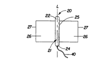
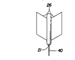
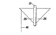
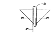
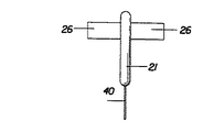
図1は、本発明のタンポン、タンポン20の1つの実施形態を示す。図1に示されるように、一般にタンポン20は、従来の圧縮吸収性コア21、およびタンポン26の側面25の少なくとも1部に取り付けられた少なくとも1枚の可撓性パネル26を備える。可撓性パネル26は、その取り付けられていないかまたは自由端27において吸収性コア21から拡張することができる。
ここで用いられる用語「タンポン」とは、膣管または他の体腔に挿入され、そこから流体を吸収するための任意のタイプの吸収構造物を言う。一般に、あるサイズおよび安定性を有するタンポンに膣内または他の体腔内への挿入を可能にするために、タンポン類は、放射方向、軸方向、または両方向に圧縮された吸収材料から構築される。ここで用いられる用語「プレジェット」または「タンポンプレジェット」は、相互に変換できるように意図され、上記のようなタンポン内にそのような構築物の圧縮前の吸収性材料の構築を言う。タンポンプレジェットは、時にはタンポンブランクスまたはソフトウィンドと称され、用語「プレジェット」は、そのような用語を同様に含むように意図されている。
【0018】
図1に示されるタンポン20の吸収性コア21は、第1端22および第2端24を有する。第1端22は、吸収性コア21の挿入端に相当する。第2端24は、吸収性コア21の引き込み端に相当する。少なくとも1つの側面25が、吸収性コア21の第1端22と第2端24との間で拡張する。側面25は、概ね吸収性コアの縦に拡張する中心軸Lに平行である。吸収性コア21は、一般に放射方向または放射および軸の双方向に円筒形状へと圧縮され得る。このような場合、吸収性コア21は、一般に円筒状吸収性コア21の側面である1つの側面25を有する。
【0019】
吸収性コア21は、円筒形状以外の他の形状に圧縮され得る。これらは、長方形、三角形、台形、半円形、または他の好適な形状として記載される断面を有する形状を含んでもよい。そのような形状において、吸収性コア21は、その形状により規定される1つ以上の側面25を有し得る。
【0020】
本発明のタンポン20の吸収性コア部21は、図2に示されるタンポンプレジェット28のような任意の好適なタンポンプレジェットから形成されてもよい。一般に、1枚または複数枚の可撓性パネル26は、吸収性コア21を形成するためにプレジェット28の圧縮前にプレジェット28に取り付けられる。この構築方法は好ましいが、幾つかの変形においては、そのようなコアをすでに自己維持フォームに圧縮した後に、1枚または複数の可撓性パネル26を吸収性コア21の側面25に取り付けることが望ましいこともある。しかしながら、好ましくは、釣り出しタンポン(図1に示されるような)は、少なくとも1枚の可撓性サイドパネル26を非圧縮状態にしたままで、図2に示されるようなプレジェット28を自己維持フォームに圧縮することにより形成され得る。圧縮されて吸収性コア21を形成するタンポン20のタンポンプレジェット28部分は、任意の好適な形状、サイズ、材料または構築物であってもよい。図2に示される実施形態において、プレジェット28は、一般に吸収体の長方形パッドである吸収性材料の綿毛である。
【0021】
図2に示されるプレジェット28は、概ね長方形であるが、台形、三角形、半球体、およびシェブロン形などの他の形状も許容できる。プレジェット28は、統合または個別の層を備える積層構造であってもよい。1つの実施形態において、プレジェット28は、外層79および外層40の間に配置される少なくとも1層の中間層81を備える。他の実施形態において、パッドは、層状構造を有する必要は全くない。プレジェット28は、折りたたみ構造を備えてもよく、巻かれてもよく、「花弁」構造またはタンポンプレジェットに関して当業界で知られているその他の構造を備えていてもよい。
【0022】
プレジェット28および結果として生じるタンポン20の吸収性コア21は、レーヨン、綿、または一般にエアフェルトと称される微粉砕木材パルプなどの吸収体に通常使用される広範な液体吸収材料から構築され得る。他の好適な吸収性材料の例として、クレープセルロースワッディング;コフォームを含むメルトブロウンポリマー;化学的剛性化、変性化または架橋化セルロース繊維;ひだをつけたポリエステル繊維などの合成繊維;ピートモス;ティッシューラップおよびティッシューラミネートを含むティッシュー;または任意の同等の材料または材料の組み合わせ、またはこれらの混合物が挙げられる。好ましい吸収性材料は、綿、レーヨン(トリロバ−ルおよび従来のレーヨン繊維、およびニードルパンチレーヨンを含む)、折りたたみティッシュー、織布材料、不織布ウェブ、合成および/または天然繊維を備える。タンポン20と他のその任意の成分は、単独材料または材料の組み合わせを備えてもよい。さらに、超吸収性ポリマーまたは吸収性ゲル化材料などの超吸収性材料を、タンポン20に組み込んでもよい。
【0023】
図1および図2に示される好ましい実施形態において、プレジェット28およびその結果生じる吸収性コア21は、レーヨン、綿(長繊維棉または糸くず棉のいずれかを含む)または他の好適な天然または合成繊維またはシートなどのソフト吸収材料から形成される。タンポン26の材料は、エアレイング、カーディング、ウェットレイングまたは他の知られた技術などの任意の好適な工程によりプレジェット28における使用のために好適である織物、ウェブまたはバットに形成され得る。
【0024】
1つの限定されない好ましい実施形態において、タンポンプレジェット28およびその結果生じる吸収性コア21は、レーヨン、綿、または両材料の組み合わせを備える。タンポンプレジェット28に用いられるレーヨンは、インビボ使用に意図された使い捨て吸収体に一般に用いられる任意の好適なタイプであっても良い。そのような許容できるタイプのレーヨンとしては、英国ハリウォールのCourtaulds Fiber社から6140レーヨンとして入手できるギャラクシー(GALAXY)レーヨン(トリローブドレーヨン構造)を含む。またCourtaulds Fiber社から入手できるサリレル(SARILLEL)レーヨン(円形繊維レーヨン)もまた好適である。任意の好適な棉材料がタンポンプレジェット28に使用できる。好適な綿材料は、長繊維綿、短繊維綿、糸くず綿、T繊維綿、カードストリップ、すき綿が挙げられる。好ましくは、綿層は、グリセリン仕上げ、レモリン仕上げまたは他の好適な仕上げで洗浄し、漂白された綿吸収体である。
【0025】
プレジェット28の吸収性材料は、望まれる場合、液体浸透性の上包み材料で囲ってもよい。そのような上包み材料は、当業界で知られているレーヨン、綿、2成分繊維、または他の好適な天然または合成繊維を含み得る。本発明のプレジェット28を層化する場合、この層は、異なる材料を含んでもよい。例えば、外層79は、主としてレーヨンを含むが、一方、1層または複数層の中間層81は、主として綿を備えてよい。任意に、プレジェット28全体は、全体をとおして均一または不均一の材料のブレンドを備えられる。
【0026】
プレジェット28は、現在入手できる従来のタンポンのものと同様のサイズを有するタンポンへの圧縮のために好適な任意のサイズと厚さであってよい。
そのようなプレジェットの代表的サイズは、約7/2インチの長さで約7/4インチの幅であってよい。総基礎重量に関する1つの好ましい範囲は、約150g/m2から約750g/m2まである。
【0027】
本発明のタンポン21はまた、吸収性コア21の側面25に取り付けられる少なくとも1枚の可撓性パネル26を備える。図1および図2に示される実施形態では、可撓性パネル26は、概ね長方形である。他の形状は、半円形(例えば、図7に示される)、台形(例えば、図10)または(例えば、図8)のような可撓性パネル24またはその部分に関して可能である。
【0028】
可撓性パネル26は、吸収性コア21の長さの約50%から約90%であることが好ましい。可撓性パネル26は、吸収性コア21の長さよりも短い長さ(軸方向に測定された)を有することが好ましいが、これらは、吸収性コア21よりも長い長さを有してもよい。可撓性パネル26の長さは、パネル26の取り付け末端からパネル26の自由端27へかけて均一である必要はない。例えば、図17は、可撓性パネル28の長さが不均一である1つの実施形態を示す。他の多くのそのような不均一な長さの実施形態がまた可能である。
【0029】
各可撓性パネル26の幅は、吸収性コア21の側縁25へのパネル26の取り付け位置から、パネル26の未取り付け(または自由な)末端27(末端は、時にはまた「末梢」端と称される)までの距離を言う。好ましくは、1枚または複数枚の各可撓性パネル26は、約2mmから約30mmで、より好ましくは、約3mmから約25mmで、最も好ましくは、約5mmから約20mmである。与えられる可撓性パネル26の幅は、その長さに沿って均一である必要はない。例えば、図10から図12は、可撓性パネル26の幅がこれらの長さに沿って均一ではない幾つかの可能な実施形態を示す。
【0030】
1枚または複数枚の可撓性パネル26のキャリパーは、好ましくは、約3mmよりも小さいか等しく、さらに好ましくは、約2mmよりも小さいか等しく、最も好ましくは、約1mmよりも小さいか等しい。ここで得られたキャリパー測定は、0.25psig負荷および0.96インチ直径のフットを有するAMESゲージを用いて測定された。0.96インチ直径のフットが、具体的なサンプルサイズにとり不適当ならば、このフットサイズを変えてもよく、これに従いゲージ上の負荷を0.25psigの制限圧を維持するように変えることを当業者らは認識するであろう。
【0031】
可撓性パネル26は、任意の好適な材料から構築されてもよい。吸収性コア21の使用に好適である上記に掲げた材料は、可撓性パネル26の使用にも受け入れられる。可撓性パネル26は、1つまたは複数のティッシュー層から構築されてもよい。1つの好適なティッシューは、ウィスコンシン州グリーンベイのFort Howard Tissue社から入手できるエアレイドティッシューであり、約35lbs./3000sq.ft. の基礎重量を有する。他の好適なエアレイドティッシューは、カナダ国ブリティッシュコロンビア州デルタのMerfin Hygenic Products社から入手でき、約61lbs./3000sq.ft. の基礎重量を有し、指定グレード番号176を有する。
【0032】
本発明のタンポン20の構築における好ましい実施例は、図1から図3に示される。この例は、図示のみが与えられ、当業者は、添付された特許請求の範囲に定義されるような種々のオプションが、本発明のタンポンを構築するのに使用できることを認識するであろう。図2に示されるタンポン20は、4枚の可撓性パネル26を備える。タンポンプレジェット28は、2つの主要面31および2つの側面29を有する長方形の綿毛材料である。図2に示される実施形態にでは、プレジェット28の主要面31に対し平行および垂直方向に配向されるプレジェット28に取り付けられる可撓性パネル26がある。図2に示されるように、タンポンが、一般にプレジェット28の主要面31に平行方向で配向される1対の可撓性パネル26を備える場合、1枚だけの可撓性パネルが用いられ得る。本材料は、プレジェット28の内部を通って拡張されるかまたは、プレジェットのいずれかの主要面28に取り付けてもよい。もちろん、1枚の材料が、プレジェット28の全体を通るかまたは横断して拡張する必要はなく、1対の可撓性パネル26は、個々にプレジェット28に取り付けられ得る。
【0033】
図2はまた、一般にプレジェット28の主要面31に垂直方向でプレッジェット28に取り付けられる1対の可撓性パネル26のそれぞれを示す。そのような構築において、各パネル26は、図2に示されるように、プレジェットに個々に取り付けてよい。例えば、取り付けタブ34では、そのような目的で使用され得る。縫い閉じ36のような任意の好適な取り付けメカニズムは、タブ34を、したがってパネル26をプレジェット28へ取り付けるために使用され得る。
【0034】
ここで用いられる用語「接合された」とは、要素を他の要素に直接的に付着させることによって、1つの要素を別の要素に直接的に固定する形態;要素を、他の要素に順に付着する中間部材に付着することによって、他の要素に間接的に固定する形態;および1つの要素を別の要素に積重ねる、すなわち1つの要素が本質的に他の要素の1部である形態を含む。
【0035】
可撓性パネル26は、種々の手段により、プレジェット26および結果として生じる吸収性コア(または予備形成の吸収性コアに直接的に)に接合され得る。例えば、可撓性パネル26は、任意の好適な接着剤を用いてプレジェット28に接合され得る。そのような接着剤は、取り付けの長さに沿って連続的に延伸するか、または個別間隔で「点付き」様式で塗布してよい。別途に、可撓性パネル26は、縫製する(縫製36のような)ことによりプレジェット28に接合され得る。そのような縫製は、綿またはレーヨン糸を用いる。他の取り付けメカニズムには、加熱接着(例えば、タンポンコアとパネルは、繊維またはそこに組み込まれた熱的接着材料を熱的に接着した)、融合接着、またはそのような材料を接合するために当業者に知られている他の好適な手段が挙げられる。
【0036】
可撓性パネル26は、タンポン20の吸収性コア21の側部25に取り付けられ、そこから吸収性コア21に取り付けられる自由端27へと外側に向けて拡張する。可撓性パネル26は、タンポン20が設置される際、膣内面に接触してパネル26維持させるように吸収性コア21から僅かに外側に向けて偏らせてもよい。さらに、膣の自然の湿り気は、膣面と接触してそれらをさらに維持させる可撓性パネル26を備える材料に接着させる傾向を有するであろう。好ましくは、可撓性パネル26は、タンポン20に存在する他の可撓性パネル26と独立する広範囲の動きを可能にする必要がある。
【0037】
可撓性パネル26は、吸収性かまたは非吸収性のいずれであってもよい。好ましくは、可撓性パネル26は、少なくとも幾つかの吸収性を有する。可撓性パネル26は、液体を優先的に吸収性コア21に向かわせ、吸収させるように、吸収性コア21の前進接触角よりも大きな前進接触角度を有し得る。任意に、可撓性パネル26は、吸収性コア21よりもそれらを小さな吸収性にさせるように処理できる。好ましくは、タンポン20により吸収され保持される大部分の液体は、究極的には吸収性コア21に保持される。親水性および接触角のより詳細な説明に関しては、ここに参照として組み込まれる以下の刊行物を参照すること:1964年に版権のあるRobert F. Gouldにより編集され、「接触角、濡れ性、および接着性」と題する米国化学会の刊行物;1992年4月に出版された「表面張力を決定する微小技術」と題するTRI/Princetonの刊行物、公表番号第459号、および1993年1月に出版された「多孔性ネットワーク内の接触角の決定」と題する公表番号第468号、双方ともH.G.Heiweil博士により編集された。
【0038】
1枚または複数枚の可撓性パネル26の主要面は無地か、またはそれは織り地であってもよい。織り地および非織り地の両方を有することは、パネル26に対する多数の実施形態において、また受け入れられる(1枚のパネル26のみが、織り地要素38を備える図2に示されるように)。好ましくは、可撓性パネル26は、織り地要素38を備え、より好ましい実施形態では、全ての可撓性パネル26が、そのような織り地要素38を備える。
【0039】
上記のように、織り地面を有するそのような可撓性パネル26の例が、図2に示される。この織り地は、図2に示されるように、多数の織り地要素38を含んで、種々の手段で供され得る。そのような織り地は、織られる可撓性パネル26の表面を針穴開けすることにより供し得る。さらに、織り地要素38は、所与の可撓性パネル26のいずれかまたは両面に取り付けられてもよい。個々の織り地要素28は、いずれの主要面からも外側に向けて拡張するために可撓性パネル26を通すことができる。さらに個々の織り地要素38は、所与の可撓性パネル26の主要面間の中間位置またはこれらの任意の組み合わせ位置に取り付けてもよい。
【0040】
好ましくは、可撓性パネル26は、そこから外側に拡張する複数の織り地要素38(外側に繊維を拡張するような)を有するプラシまたはテリ−クロスタイプの織物を備える主要面を有する。織り地要素38は、ランダムに配向されてもよく、または1つまたは複数の特定の方向に整列されてもよい。好ましくは、これらの織り地要素38は、一般に可撓性パネル26の表面に対し垂直である。これらの織り地要素38は、膣腔のルゴサイト(rugosite)中に貫通して月経をさえぎり、かつ「バイパス」という不成功(月経がこれらのルゴサイトおよびタンポンの周囲へ移動することによる不成功)を低減する。好ましくは、織り地要素38は、膣表面により働く力に応じてそれら自体で曲がりおよび/または配向する傾向を有し得る。
【0041】
織り地要素38は、ループ状であってもよく、両端で可撓性パネル26の表面に取り付けられる。好適な織り地要素は、可撓性パネル26の表面内および表面外にパンチされ複数のループを形成する単一の長繊維または一連の繊維から形成され得る。特記したように、所与の可撓性パネル26の両側、1つの側に織り地38を備えてもよく、またはいずれの側もそれを備えなくてもよい。
【0042】
織り地要素38は、好ましくは、液体を膣表面から可撓性パネル26の主要面、および究極的には吸収性コア21への迅速に移動し易くするように親水性である。密度勾配、親水性勾配、浸透駆動力または同様のメカニズムの利用により、織り地要素38はまた、液体を膣面から可撓性パネル26の主要面へ、究極的には吸収性コア21に移動するように構成され得る。そのような液体捕捉/移動メカニズムに使用する好適な材料は、レーヨン(例えば、従来のトリローブまたはマルチローブレーヨン繊維を含む)、ポリエチレン、ポリプロピレン、ポリエステル、合成2成分繊維、吸収性フォームおよびそれらの組み合わせがあり、それら繊維の全ては、単独に或いは他の繊維と組み合わせるかのいずれかで用いることができることは当業者に知られている。毛細管繊維は、織り地要素38にとって非常に好ましい繊維である。
【0043】
可撓性パネル26に関する好ましい材料は、モデル番号C120としてオハイオ州シンシナチーのEmpirical Manufacturing社から入手できるコットンインターロックとして知られている。これは、テリークロスまたはテリータオルと同様の綿織物である。
【0044】
可撓性パネル26は、挿入、除去を容易にするためにまたは他の目的のために洗浄組成物または潤滑組成物を任意に備える。可撓性パネル26は、好ましくは、捕捉液体を可撓性パネル26から吸収性コア21に優先的に方向付けるために、組み込みメカニズム有してもよく、また好ましくは有する必要がある。そのようなメカニズムは、織り地要素38に関して上記のもの何れであってもよい。
【0045】
可撓性パネル26は、1つ以上の方向に拡張できるかまたは伸張し得る。これは、固有の伸張できる材料または1つまたは複数の層が伸張できるかまたは拡張できるラミネートからの可撓性パネル26の構築を介して達成できる。さらに、可撓性パネル26を構成する材料は、リングローリングまたは波形を作るような好適な機械工程により拡張可能にすることができる。可撓性パネル26はまた、拡張可能な小片または要素を組み込んでもよい。
【0046】
可撓性パネル26は、それらを快適にさせかつ膣の動きに対して動的に適合できる強度と剛性を有する必要がある。好ましくは、可撓性パネル26は、タンポン20の除去の際、装着者の膣に留まっている断片を残す恐れがある寸断および/またはちぎれからそれらを防止するために十分な強度を有することが好ましい。同様に、可撓性パネル26は、膣の動きに動的に調和するように十分な可撓性を有する必要がある。
【0047】
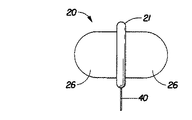
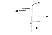
図1および図2に例が示される回収コード40は、使用後タンポンの除去のために一般にタンポン20に取り付けられる。回収コード48は、縫い付け、接着剤取り付け、または知られた接着方法の組み合わせを含む当業者に知られる任意の好適な方法で取り付け得る。回収コード40は、吸収性または非吸収性であってもよく、好ましくは非吸収性である。回収コード40は、タンポン20の任意の好適な位置に取り付けてよい。図1および図2に示される実施形態において、1本の回収コード40は、吸収性コア21の第2端24に取り付けられる。回収コード40は、タンポンプレジェット28は、未だ圧縮されていない間に、図2に示されるように、一般にタンポンプレジェット28に取り付けられる。回収コード40は、プレジェット28の1つの主要面の全長に沿って取り付けされ、そして第2端24のような1端から離れて垂れている。
【0048】
本発明のタンポンの1変形において、タンポンは、図11に示されるように、回収コード46を取り付けた可撓性パネルを備えることができる。言い換えれば、回収コード26は、1枚の可撓性パネル26上の任意の好適な位置に取り付けられてもよい。好ましくは、回収コードを取り付けたそのようなパネルは、可撓性パネル26の自由端の最も近くに取り付けられる。
【0049】
図12は、回収コードが、タンポンの吸収性コア21部に取り付けられるが、しかし第1端22(または挿入端)に取り付けられる別の変形を示す。そのような取り付け位置は、挿入後の回転、または他の操作のためにタンポンの挿入後、使用者が回収コード40を引張ることを可能にする。何人かの使用者は、タンポンを膣管において主に縦よりも一般に横の関係に配置する方を好むであろう。さらに、何人かの使用者は、挿入後タンポンを完全に回転するために回収コード40を取り付けた挿入端を用いるであろう。そのような完全な回転は、可撓性パネル26が拡張して、さらに効果的に膣内部の表面を覆うことを助けるができる。
【0050】
図13に示されるように、本発明のタンポンはまた、可撓性パネルの操作用コード48を備えてもよい。そのようなパネル操作用コードは、任意であるが、タンポンに備えられた任意の可撓性26は、任意の好適な位置に取り付けたコードを有することができる。そのようなコードは、タンポン自体の挿入後可撓性パネル26の動きを制御させるために使用者により用いられ得る。
【0051】
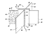
使用を速やかにさせるタンポンを形成するために。タンポンプレジェット28は、一般に圧縮され、任意の好適な従来の方法で加熱調整される。この目的に好適な圧と温度は、当業界でよく知られている。一般に、プレジェット28は、当業界でよく知られている任意の手段を用いて放射および軸方向の両方で圧縮される。多様な技術が知られ、これらの目的に受け入れられるが、ヴァージニア州リッチモンドのHauni Machines社から入手できる改造タンポン用圧縮機が好適である。好ましくは、可撓性パネル26は、図2に示されるように圧縮されていないプレッジェト28に取り付けられる。次いで、プレッジェト28は、図3に示されるように吸収性コア21に圧縮され得る。図3は、可撓性パネルを26を圧縮することなく吸収性コア21の圧縮を可能にする狭い軸のスリットを備えられた一連の圧縮ダイス44を示す。幾つかの実施例において、そのような吸収性コアの圧縮後に可撓性パネル26を、吸収性コア21に取り付けることもまた望ましいことであろう。
【0052】
本発明のタンポン20は、指にて挿入するか、またはアプリケーターを介して挿入してもよい。タンポン20が、指による挿入に使用される場合、円筒形に巻かれた吸収性材料の層からプレジェットを形成することが望ましいかもしれない。可撓性パネル26は、任意の好適な方法でそのような層に取り付けることができるであろう。例えば、図2に示された取り付けタブ34は、1枚または複数枚の可撓性パネル26を、巻かれているプレジェットに取り付けるために使用され得る。
【0053】
現在入手できる任意のタンポンアプリケーターが、本発明のタンポンの挿入用に用いることができる。一般に、「チューブおよびプランジャー」タイプの配置のそのようなアプリケーターは、プラスティック、紙または他の好適な材料であってよい。さらに「コンパクト」タイプのアプリケーターはまた、好適である。可撓性パネル26の可撓性により、それらはタンポンの吸収性コア21に沿ってタンポンとともにアプリケーターチューブ内に存することができる。アプリケータープランジャーは、圧縮されたコアの性質により吸収性コア21をアプリケーターから押出す。次いで、可撓性拡張の26は、それらの全体的に圧縮されていない状態から挿入後、直ちに液体を集め始めるために利用できる。
【0054】
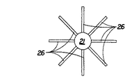
記載したように、本発明のタンポンは、少なくとも1枚の可撓性パネルを有する。好ましくは、2枚から4枚の間で可撓性パネル26が存在する。図4は、2枚のパネルを有する本発明のタンポンの1例を示す。図5は、3枚のそのような可撓性パネルを示す。図6は、8枚の可撓性パネル26を有する実施形態を示す。必要ではないが、パネル26は、吸収性コア21の周囲にほぼ規則正しく間隔を空けることが好ましい。図7から図10および図14から図17は、可撓性パネル26にとって可能な種々の変化例を示す。これらの例は、徹底してはいなく他の変化も可能である。
【0055】
全ての特許、特許出願(および、対応して公表された如何なる外国特許出願と同様にそれに発行される如何なる特許)の開示、および本特許出願を通して述べられた刊行物は、ここに参照として組み込まれる。しかしながら、ここで参照として組み込まれた如何なる文書にも、本発明を教示するかまたは開示することを明確には認められない。また、ここで記載された如何なる商品として入手できる材料または製品にも、本発明を教示するかまたは開示することが明確には認められない。
【0056】
本明細書(関連出願部分に交差する引用文献に掲げたものを含む)に参照した全ての特許および特許出願の開示は、ここに完全に述べられたように参照としてここに組み込まれる。本発明の個々の実施形態は、図示され説明されたが、種々の他の変化および修飾が、本発明の精神および範囲から逸脱することなく作製できることは、当業者らにとって明らかになるであろう。
【0057】
本明細書は、本発明を形成すると考えられる課題を具体的に指摘し、明確に請求する特許請求の範囲により結論づけるが、本発明は、添付する図面と合わせて上記の説明からより良く理解されると思われ、ここでは同一の参照符号は、同一の要素を指している。
【図面の簡単な説明】
【図1】 図1は、圧縮吸収性コアおよび1対の可撓性サイドパネルを有する本発明のタンポンの正面図である。
【図2】 図2は、吸収性コアの圧縮前における、可撓性サイドパネルのうちの1枚に織り要素を示す本発明のタンポンの正面図である。
【図3】 図3は、本発明のタンポンの吸収性コアが圧縮され得る1つの方法を示す平面図である。
【図4】 図4は、2枚の可撓性パネルを有する本発明のタンポンにおける1つの実施形態の平面図である。
【図5】 図5は、3枚の可撓性パネルを有する本発明のタンポンにおける1つの実施形態の平面図である。
【図6】 図6は、8枚の可撓性パネルを有する本発明のタンポンにおける1つの実施形態の平面図である。
【図7】 図7は、半円形部の付いた可撓性パネルを有する本発明のタンポンにおける1つの実施形態の正面図である。
【図8】 図8は、三角形の可撓性パネルを有する本発明のタンポンにおける1つの実施形態の正面図である。
【図9】 図9は、可撓性パネルの別の形態を示す本発明のタンポンにおける1つの実施形態の正面図である。
【図10】 図10は、台形の可撓性パネルを有する本発明のタンポンにおける1つの実施形態を示す。
【図11】 図11は、可撓性パネルの1枚に取り付けられた回収コードを有する本発明のタンポンにおける1つの実施形態を示す。
【図12】 図12は、回収コードが、吸収性コアの挿入端に取り付けられる本発明のタンポンにおける1つの実施形態の正面図である。
【図13】 図13は、圧縮コアに取り付けられた主回収コードを有し、可撓性パネルの操作コードを有する本発明のタンポンの正面図である。
【図14】 図14は、本発明のタンポンにおける別の実施形態の正面図である。
【図15】 図15は、オフセット可撓性拡張を有する本発明のタンポンにおける別の実施形態の正面図である。
【図16】 図16は、部分的にオフセット可撓性拡張を有する本発明のタンポンにおける別の実施形態の正面図である。
【図17】 図17は、可撓性拡張の別の形状を有する本発明のタンポンにおける別の実施形態の正面図である。[0001]
(Field of Invention)
The present invention relates to a menstrual tampon, and more specifically, at least one sheet for improving the compression core and the reach to the interior of the vaginal cavity and for directing fluid toward the tampon core. The present invention relates to an improved tampon having a flexible panel.
(Background of the Invention)
It has long been recognized that the interior of the vaginal cavity in a normal collapsed state is much wider in cross-section than in the vertical plane. It is equally well known that the minimum dimension of the vagina is near the entrance, while this maximum dimension is near the cervix. Therefore, when considering a tampon for menstrual use, it is sized and / or shaped to pass through the vaginal opening without discomfort in the first state, especially once inside the vaginal cavity and beyond the entrance restrictions When stretched in the direction, it is desirable to provide a structure that substantially contacts all surfaces of the vaginal wall from one side of the vaginal cavity to the other side to prevent premature bypass of menstrual excretion from the cervix . The vaginal wall in normal collapsed state is relaxed and has a large number of folds and wrinkles that provide a path for a significant portion of menstrual fluid to flow out, so it conforms to the shape of the vaginal cavity and minimizes leakage It is also important that the absorbent tampon be as flexible and adaptable as possible in order to fit within these pathways.
[0002]
Absorbent menstrual tampons currently in common use have a diameter of about 3/8 to 0.5 inch (about 1.0 cm to 1.3 cm) and a length of 3/2 to 5/2 inch. It is small (approximately 3.8 cm to 6.4 cm) and has a highly compressed cylindrical plug. In order to require absorption capacity, they are usually formed from fluff of a size much larger than the vaginal opening and compressed to the small size described above to facilitate insertion. As fluid is absorbed, these compressed tampons re-expand in the originally pre-compressed size direction, so that they are large enough to effectively cover the vaginal cavity against fluid leakage or bypass. Is expected to be. These compressed tampons have been found to perform their intended function fairly well, but even if a vertical block is sufficient (such a vertical block may also be missing) However, even these best do not re-expand sufficiently or quickly to provide a good lateral reach for leaks. Furthermore, most of these tampons often leak out using only a small portion of their absorption capacity. Since these tampons rely on some degree of liquid absorption to re-expand, it is clear that liquid bypass and leakage can occur early, especially immediately after insertion.
[0003]
In the prior art, it has long been recognized that it would be desirable to provide a tampon that can be expanded immediately after insertion, particularly in the lateral or lateral direction. Immediate expansion of the menstrual tampon is most advantageously provided when it does not rely on absorption of body fluids for such expansion. “Dry expansion” is a term frequently used in the industry to describe such tampons.
[0004]
Many attempts have been made to solve the above problems with compressed cylindrical tampon by using dry expanded tampon. Some of these approaches focused on the applicator, and others focused on the tampon itself.
[0005]
For example, some approaches in the patent art suggest tampon with built-in mechanical expansion means, a representative example being US Pat. No. 3,706,311 to Kohx et al. However, although a good transverse block appears to occur, the mechanical expansion means disclosed in the patent is in the form of a flat spring-like element that maintains the extended form of the tampon semi-permanently after insertion, May be difficult to remove.
[0006]
Another approach is described in US Pat. No. 3,512,528 to Whitehead et al., Which is extended by the introduction of an absorbent material folded to a small size for insertion, and a gas or liquid inside the sac after insertion. Teaches the use of sack. When using this type of tampon, many steps and complicated operations of gas or liquid introduction are required, which would otherwise undermine what would otherwise apparently solve this problem effectively. ing.
[0007]
Yet another approach is described in US Pat. No. 3,857,395 to Johnson et al. The Johnson et al. Patent teaches the use of an elongated inserter device in which a flat tampon is crimped. The insert is said to allow the tampon fold from the point where the tampon is supported at the tip of the insert to be pulled rather than pushed into the cavity. The means of the insert comprises a bilateral expansion mechanism that allows the tampon to be manipulated laterally during insertion at the user's discretion. However, the inserter device described in the Johnson et al. Patent has a number of disadvantages. Johnson's inserter device is a complex device that provides a pair of hinge arms that can be bifurcated to the sides with hinges or joints. The angular nature of the hinge arm will make the use of the insert uncomfortable. The complex nature of the hinge arm will make manufacture difficult and costly. As a result, it will not be suitable as a disposable applicator.
[0008]
It has been recognized in the prior art that a tampon should ideally be highly compatible and as rigid as possible. However, as the above prior art attempts show, such tampon is difficult to insert and operate in the expanded position. Thus, all prior art attempts to provide a dry expansion tampon require an application system that can be complicated, cumbersome and uncomfortable, or a semi-rigid tampon or a tampon with a mechanical expansion mechanism. Was building.
[0009]
Another series of attempts to overcome the problems associated with conventional high compression, liquid expansion tampon are US Pat. No. 3,749,094 issued to Duncan and two US patents issued to Dulle. No. 3,794,029 and US Pat. No. 3,766,921. The Duncan and Dulle devices are all generally conical and are designed for dry expansion. While these devices would be expected to overcome some of the problems associated with high compression and liquid expansion tampons, Duncan and Dulle devices are the traditional “tube and plunger” type that they are designed for In order to allow their applicators to utilize them, they still require considerable stiffness and compression. Such tampons are also constructed from absorbent polyurethane foam to provide the required “spring”.
[0010]
It would be desirable to provide a menstrual tampon that can be constructed from materials such as rayon and cotton that have been used for a long time in the industry for menstruation and other vaginal discharges.
Such materials are accepted as safe and effective for such in vivo applications, are readily available, and are sufficiently inexpensive for disposable product applications. It is desirable to design a tampon that can be inserted by finger or by use of a conventional “tube and plunger” applicator. This is because such applicators are well accepted by consumers, are simple to manufacture and are inexpensive. It is also desirable to provide a tampon in which at least a portion of the tampon is dry expanded to immediately cover a substantial portion of the vagina. Such dry extensions need to be highly relaxed and adaptable in order to conform to the surface inside the vagina.
[0011]
The present invention seeks to combine the advantages of a conventional tampon with an absorbent body compressed into a self-sustaining foam with the advantages of a dry expansion tampon. One prior attempt to provide such a tampon is described in US Pat. No. 4,212,301 issued to Johnson. This Johnson patent describes a finger tampon having a portion made from an absorbent material that is compressed into a self-sustaining foam. The upper part of Johnson's device is left uncompressed to provide a finger fold during insertion. Although Johnson's device seems to combine some of the advantages of conventional compressed tampon with the advantage of leaving an uncompressed part, Johnson's device still has some major drawbacks. Since some parts of Johnson's device are not compressed, dry expansion may only be added to the top of the compressed part. This limits the ability of the uncompressed portion to direct the captured liquid to the “core” portion of the tampon for long term storage. Indeed, according to Johnson's disclosure, the uncompressed portion appears to serve a function as a finger seal during insertion rather than as a liquid capture aid specific to the present invention.
(Summary of Invention)
The present invention relates to a menstrual tampon, and more specifically, a central absorbent core having a first end, a second end disposed opposite the first end, and a first end and a second end. The present invention relates to an improved tampon having a side surface extending between ends. The first end of the central absorbent core corresponds to the insertion end of the tampon. The sides are oriented in a direction that is generally parallel to the longitudinal axis of the tampon. The central absorbent core is constructed from an absorbent material that is compressed into a self-sustaining foam. The tampon further comprises at least one flexible panel joined to the central absorbent core along the side of at least a portion of the core. The flexible panel extends outward from this joint of the core. The tampon also includes a retrieval cord attached to and extending from the tampon.
[0012]
In one embodiment, the one or more flexible panels are generally rectangular. Separately, the one or more flexible panels are triangular, semicircular, or trapezoidal.
[0013]
In one embodiment, the tampon may have 2 to 20 flexible panels. In a particularly preferred embodiment, the tampon can have 2 to 4 flexible panels.
[0014]
The retractable core in one embodiment may be attached to the central absorbent core of the tampon. This attachment may be the first end of the central absorbent core in one embodiment, or the second end of the central absorbent core in another embodiment. The retrieval cord may also be attached to the flexible panel to allow operation of the panel with final withdrawal of the tampon. In further embodiments, multiple cords may be attached to the tampon to allow both tampon retraction and post-insertion operation.
[0015]
In one preferred embodiment, the one or more flexible panels are at least partially absorbent. In a preferred embodiment, the one or more flexible panels comprise a drive mechanism that directs liquid to the central absorbent core of the tampon. In particularly preferred embodiments, the drive mechanism is provided by the use of capillary fibers, osmotic drive forces, or hydrophilic gradients, or some combination thereof.
[0016]
The tampon is preferably constructed from rayon or cotton or some combination thereof.
(Detailed Description of the Invention)
The present invention relates to a menstrual tampon, and more particularly, at least one piece for improving the reach of the compression core and the vaginal cavity and for leading the trapped fluid to the tampon core. It relates to an improved tampon having a flexible panel.
[0017]
FIG. 1 shows one embodiment of a tampon,
The term “tampon” as used herein refers to any type of absorbent structure that is inserted into and absorbs fluid from a vaginal canal or other body cavity. In general, tampons are constructed from absorbent material compressed radially, axially, or in both directions to allow insertion of a tampon of certain size and stability into the vagina or other body cavity. . The term “prejet” or “tampon ljet” as used herein is intended to be interchangeable and refers to the construction of an absorbent material prior to compression of such a construct in a tampon as described above. A tampon pledget is sometimes referred to as a tampon blank or soft window, and the term “prejet” is intended to include such terms as well.
[0018]
The
[0019]
The
[0020]
The
[0021]
The
[0022]
The pre-jet 28 and the
[0023]
In the preferred embodiment shown in FIGS. 1 and 2, the
[0024]
In one non-limiting preferred embodiment, the
[0025]
The absorbent material of the
[0026]
The
A typical size of such a prejet may be about 7/2 inches long and about 7/4 inches wide. One preferred range for total basis weight is about 150 g / m. 2 To about 750 g / m 2 There is.
[0027]
The
[0028]
The
[0029]
The width of each
[0030]
The caliper of one or more
[0031]
The
[0032]
A preferred embodiment in the construction of the
[0033]
FIG. 2 also shows each of a pair of
[0034]
As used herein, the term “joined” refers to a form in which one element is directly secured to another element by attaching the element directly to another element; A form that is indirectly fixed to another element by attaching to an attached intermediate member; and a form in which one element is stacked on another element, ie one element is essentially a part of the other element including.
[0035]
The
[0036]
The
[0037]
The
[0038]
The major surface of the one or more
[0039]
An example of such a
[0040]
Preferably, the
[0041]
The woven
[0042]
The woven
[0043]
A preferred material for
[0044]
The
[0045]
The
[0046]
The
[0047]
1 and 2 is generally attached to the
[0048]
In one variation of the tampon of the present invention, the tampon can comprise a flexible panel with a
[0049]
FIG. 12 shows another variation where the retrieval cord is attached to the
[0050]
As shown in FIG. 13, the tampon of the present invention may also include a flexible
[0051]
To form a tampon that allows for rapid use. The
[0052]
The
[0053]
Any currently available tampon applicator can be used for insertion of the tampon of the present invention. In general, such applicators in a “tube and plunger” type arrangement may be plastic, paper or other suitable material. Furthermore, “compact” type applicators are also suitable. Due to the flexibility of the
[0054]
As described, the tampon of the present invention has at least one flexible panel. Preferably there are between 2 and 4
[0055]
The disclosures of all patents, patent applications (and any patents issued to them as well as any correspondingly published foreign patent applications), and publications mentioned throughout this patent application are incorporated herein by reference. . It is expressly not admitted, however, that any document incorporated herein by reference teaches or discloses the present invention. In addition, it is not expressly recognized that the present invention is taught or disclosed in any commercially available material or product described herein.
[0056]
The disclosures of all patents and patent applications referred to herein (including those listed in the cited references crossing related application portions) are hereby incorporated by reference as if fully set forth herein. While particular embodiments of the present invention have been illustrated and described, it will be apparent to those skilled in the art that various other changes and modifications can be made without departing from the spirit and scope of the invention. .
[0057]
The specification concludes with the claims that particularly point out and distinctly claim the subject believed to form the invention, but the invention will be better understood from the foregoing description in conjunction with the appended drawings. It is assumed that the same reference numerals here refer to the same elements.
[Brief description of the drawings]
FIG. 1 is a front view of a tampon of the present invention having a compressible absorbent core and a pair of flexible side panels.
FIG. 2 is a front view of a tampon of the present invention showing a woven element on one of the flexible side panels prior to compression of the absorbent core.
FIG. 3 is a plan view illustrating one way in which the absorbent core of the tampon of the present invention may be compressed.
FIG. 4 is a plan view of one embodiment of a tampon of the present invention having two flexible panels.
FIG. 5 is a plan view of one embodiment of a tampon of the present invention having three flexible panels.
FIG. 6 is a plan view of one embodiment of a tampon of the present invention having eight flexible panels.
FIG. 7 is a front view of one embodiment of a tampon of the present invention having a flexible panel with a semi-circular portion.
FIG. 8 is a front view of one embodiment of a tampon of the present invention having a triangular flexible panel.
FIG. 9 is a front view of one embodiment of the tampon of the present invention showing another form of flexible panel.
FIG. 10 illustrates one embodiment of a tampon of the present invention having a trapezoidal flexible panel.
FIG. 11 illustrates one embodiment of a tampon of the present invention having a retrieval cord attached to one of the flexible panels.
FIG. 12 is a front view of one embodiment of a tampon of the present invention in which a retrieval cord is attached to the insertion end of the absorbent core.
FIG. 13 is a front view of a tampon of the present invention having a main recovery cord attached to a compression core and a flexible panel operating cord.
FIG. 14 is a front view of another embodiment of the tampon of the present invention.
FIG. 15 is a front view of another embodiment of a tampon of the present invention having an offset flexible extension.
FIG. 16 is a front view of another embodiment of a tampon of the present invention having a partially offset flexible extension.
FIG. 17 is a front view of another embodiment of a tampon of the present invention having another shape of flexible expansion.
Claims (11)
少なくとも1部の前記側面に沿って前記中心吸収性コアに接合される少なくとも1枚の可撓性パネルであって、前記中心吸収性コアから外側に向けて拡張する前記の少なくとも1枚の可撓性パネル、および、
前記タンポンに接合され、そこから延びている回収コードを具備し、
前記の少なくとも1枚の可撓性パネルが、少なくとも部分的に吸収性であり、前記の少なくとも1枚の可撓性パネルが、捕捉した液体を可撓性パネルから吸収性コアに方向付けるための駆動メカニズムを備えている、月経用タンポン。A central absorbent core having a first end, a second end disposed opposite the first end, and a side surface extending between the first end and the second end, The central absorbent core constructed from an absorbent body, wherein the first end corresponds to an insertion end of a tampon, the side surface is oriented in a direction parallel to a longitudinally extending central axis and compressed into a self-maintaining foam;
At least one flexible panel joined to the central absorbent core along at least a portion of the side surface, the at least one flexible panel extending outward from the central absorbent core. Sex panels, and
A recovery cord joined to and extending from the tampon ;
The at least one flexible panel is at least partially absorbent, and the at least one flexible panel is for directing captured liquid from the flexible panel to the absorbent core. Menstrual tampon equipped with a drive mechanism .
Applications Claiming Priority (9)
| Application Number | Priority Date | Filing Date | Title |
|---|---|---|---|
| US09/124,351 | 1998-07-29 | ||
| US09/124,407 | 1998-07-29 | ||
| US09/124,351 US6095998A (en) | 1998-07-29 | 1998-07-29 | Expandable bag tampon and spreading tampon applicator therefor |
| US09/124,407 US6302861B2 (en) | 1998-07-29 | 1998-07-29 | Spreading tampon applicator |
| US09/177,221 US6358235B1 (en) | 1998-07-29 | 1998-10-22 | Soft conformable hollow bag tampon |
| US09/177,221 | 1998-10-22 | ||
| US09/287,994 | 1999-04-08 | ||
| US09/287,994 US6206867B1 (en) | 1998-07-29 | 1999-04-08 | Tampon with flexible panels |
| PCT/US1999/017157 WO2000006070A1 (en) | 1998-07-29 | 1999-07-29 | Tampon with flexible panels |
Publications (3)
| Publication Number | Publication Date |
|---|---|
| JP2002521133A JP2002521133A (en) | 2002-07-16 |
| JP2002521133A5 JP2002521133A5 (en) | 2006-08-31 |
| JP4459446B2 true JP4459446B2 (en) | 2010-04-28 |
Family
ID=27494535
Family Applications (1)
| Application Number | Title | Priority Date | Filing Date |
|---|---|---|---|
| JP2000561927A Expired - Fee Related JP4459446B2 (en) | 1998-07-29 | 1999-07-29 | Tampon with flexible panel |
Country Status (12)
| Country | Link |
|---|---|
| US (1) | US6206867B1 (en) |
| EP (1) | EP1100424B1 (en) |
| JP (1) | JP4459446B2 (en) |
| KR (1) | KR20010072058A (en) |
| CN (1) | CN1310602A (en) |
| AT (1) | ATE238017T1 (en) |
| AU (1) | AU748284B2 (en) |
| BR (1) | BR9912452A (en) |
| CA (1) | CA2336394A1 (en) |
| DE (1) | DE69907207T2 (en) |
| MX (1) | MXPA00012996A (en) |
| WO (1) | WO2000006070A1 (en) |
Families Citing this family (58)
| Publication number | Priority date | Publication date | Assignee | Title |
|---|---|---|---|---|
| US20030004435A1 (en) * | 2001-06-28 | 2003-01-02 | Crawford Paul G. | Device for collecting cellular & DNA specimens |
| US7727208B2 (en) | 2002-09-12 | 2010-06-01 | Playtex Products, Inc. | Ergonomic tampon applicator |
| US9192522B2 (en) | 2003-05-02 | 2015-11-24 | Eveready Battery Company, Inc. | Tampon assembly having shaped pledget |
| WO2004098449A2 (en) | 2003-05-02 | 2004-11-18 | Playtex Products, Inc. | Tampon assembly having shaped pledget |
| US7214218B2 (en) * | 2003-11-21 | 2007-05-08 | The Procter & Gamble Company | Tampon with raised portions having multiple widths |
| EP1547554A1 (en) * | 2003-12-22 | 2005-06-29 | Ontex N.V. | Absorbent article |
| ES2309404T3 (en) * | 2004-02-05 | 2008-12-16 | THE PROCTER & GAMBLE COMPANY | TAMPON WITH DISPLACED SLOTS. |
| US8653322B2 (en) * | 2004-05-14 | 2014-02-18 | Mcneil-Ppc, Inc. | Intravaginal device with fluid transport plates |
| US8864640B2 (en) * | 2004-05-14 | 2014-10-21 | Mcneil-Ppc, Inc. | Methods of packaging intravaginal device |
| US20050256484A1 (en) * | 2004-05-14 | 2005-11-17 | Chase David J | Method of using an intravaginal device with fluid transport plates |
| US20050277904A1 (en) * | 2004-05-14 | 2005-12-15 | Chase David J | Tampon with flexible panels |
| US8247642B2 (en) * | 2004-05-14 | 2012-08-21 | Mcneil-Ppc, Inc. | Fluid management device with fluid transport element for use within a body |
| US7845380B2 (en) * | 2004-05-14 | 2010-12-07 | Mcneil-Ppc, Inc. | Intravaginal device with fluid transport plates |
| AU2011206948B2 (en) * | 2004-05-14 | 2012-04-05 | Johnson & Johnson Consumer Inc. | Intravaginal device with fluid transport plates |
| US7618403B2 (en) * | 2004-05-14 | 2009-11-17 | Mcneil-Ppc, Inc. | Fluid management device with fluid transport element for use within a body |
| US20050256485A1 (en) | 2004-05-14 | 2005-11-17 | Samuel Carasso | Method of using intravaginal device with fluid transport plates |
| US8480833B2 (en) * | 2004-05-14 | 2013-07-09 | Mcneil-Ppc, Inc. | Intravaginal device with fluid transport plates and methods of making |
| DE602005025113D1 (en) * | 2004-05-14 | 2011-01-13 | Johnson & Johnson Consumer | INTRAVAGINAL DEVICE WITH LIQUID TRANSPORT PLATES AND MANUFACTURING METHOD |
| WO2005112862A1 (en) | 2004-05-14 | 2005-12-01 | Johnson & Johnson Consumer Companies, Inc. | Methods of packaging intravaginal device |
| AU2011206947B2 (en) * | 2004-05-14 | 2013-01-24 | Johnson & Johnson Consumer Inc. | Method of using intravaginal device with fluid transport plates |
| EP1755515B1 (en) * | 2004-05-14 | 2018-10-17 | Johnson & Johnson Consumer Inc. | Intravaginal device with fluid transport plates |
| AU2011207948B2 (en) * | 2004-05-14 | 2012-07-12 | Johnson & Johnson Consumer Inc. | Intravaginal device with fluid transport plates and methods of making |
| US8702670B2 (en) * | 2004-06-30 | 2014-04-22 | Mcneil-Ppc, Inc. | Intravaginal device with controlled expansion |
| ATE526922T1 (en) * | 2005-01-19 | 2011-10-15 | Ontex Internat N V | TAMPON |
| ATE370715T1 (en) * | 2005-02-24 | 2007-09-15 | Ontex Internat N V | TAMPON INSERTION AID |
| ATE408388T1 (en) * | 2005-03-25 | 2008-10-15 | Georgia Pacific France | TAMPON AND APPLICATOR ASSEMBLY |
| US7537587B2 (en) * | 2005-05-23 | 2009-05-26 | Rusl, Llc | System comprising thong-shaped holder and absorbent article |
| US20060264879A1 (en) * | 2005-05-23 | 2006-11-23 | Carstens Jerry E | System comprising thong-shaped holder and absorbent articles |
| US7458961B2 (en) | 2005-05-23 | 2008-12-02 | Rusl, Llc | Thong-shaped holder for use with absorbent article |
| US7481801B2 (en) * | 2005-05-23 | 2009-01-27 | Rusl, Llc | System comprising thong-shaped holder and absorbent article |
| US20060264865A1 (en) * | 2005-05-23 | 2006-11-23 | Carstens Jerry E | System comprising thong-shaped holder and absorbent interlabial article |
| US20060264872A1 (en) * | 2005-05-23 | 2006-11-23 | Carstens Jerry E | System comprising thong-shaped holder and absorbent article |
| US20060264870A1 (en) * | 2005-05-23 | 2006-11-23 | Carstens Jerry E | System comprising thong-shaped holder and absorbent article |
| US20070142816A1 (en) * | 2005-12-19 | 2007-06-21 | Carstens Jerry E | Absorbent article and system comprising thong-shaped holder |
| US7867211B2 (en) | 2005-05-23 | 2011-01-11 | Rusl, Llc | System comprising thong-shaped holder and absorbent article |
| US20060264873A1 (en) * | 2005-05-23 | 2006-11-23 | Carstens Jerry E | System comprising thong-shaped holder and absorbent article |
| US20060264868A1 (en) * | 2005-05-23 | 2006-11-23 | Carstens Jerry E | System comprising thong-shaped holder and article with sensor |
| US20060264871A1 (en) * | 2005-05-23 | 2006-11-23 | Carstens Jerry E | System comprising thong-shaped holder and absorbent article |
| US7462173B2 (en) * | 2005-05-23 | 2008-12-09 | Rusl, Llc | System comprising thong-shaped holder and absorbent article |
| DE102005042012B4 (en) * | 2005-09-02 | 2010-06-10 | Drescher, Rüdiger | tampon |
| RU2406473C2 (en) | 2006-02-02 | 2010-12-20 | Онтекс Хюгиенеартикель Дойчланд Гмбх | Tampon |
| EP2664311A1 (en) | 2006-06-12 | 2013-11-20 | Playtex Products, Inc. | Tampon Assembly Providing Proper Bodily Placement of a Pledget |
| US7554384B2 (en) * | 2006-06-30 | 2009-06-30 | Intel Corporation | Methods and arrangements for generating a control signal for a power converter |
| CN101541280B (en) * | 2006-06-30 | 2012-04-18 | 麦克内尔-Ppc股份有限公司 | An intravaginal device with fluid transport plates |
| US8147471B2 (en) * | 2006-09-11 | 2012-04-03 | Merimont Us | Sanitary napkin with braid |
| EP2079422A4 (en) * | 2006-11-08 | 2011-09-07 | Playtex Products Inc | Tampon pledget for increased bypass leakage protection |
| WO2008095937A2 (en) * | 2007-02-09 | 2008-08-14 | Ontex Hygieneartikel Deutschland Gmbh | Tampon |
| US8597267B2 (en) * | 2007-04-18 | 2013-12-03 | The Procter & Gamble Company | Tampon having at least one physical discontinuity |
| US20110230854A1 (en) * | 2008-11-13 | 2011-09-22 | Ontex Hygieneartikel Deutschland Gmbh | Tampon with a perforated outer cover |
| EP2379036A1 (en) * | 2008-12-16 | 2011-10-26 | Ontex Hygieneartikel Deutschland GmbH | Tampon with modified constricted withdrawal end |
| US9155666B2 (en) | 2010-07-09 | 2015-10-13 | Ontex Higieneartikel Deutschland Gmbh | Press and method for producinig absorbent article |
| GB201201645D0 (en) * | 2012-01-31 | 2012-03-14 | Ge Healthcare Ltd | Improvements in and relating to biological sample collection |
| EP4166121A1 (en) | 2014-07-18 | 2023-04-19 | The Procter & Gamble Company | Tampon and method of making |
| US11096677B2 (en) * | 2014-09-18 | 2021-08-24 | Covidien Lp | Regions of varying physical properties in a compressible cell collection device |
| US11071656B2 (en) | 2016-11-07 | 2021-07-27 | The Procter & Gamble Company | Tampon and method for making the same |
| US11497656B2 (en) | 2016-11-07 | 2022-11-15 | The Procter & Gamble Company | Tampon and method for making the same |
| US11439803B2 (en) | 2019-01-31 | 2022-09-13 | Niva Medtech LLC | Medicant applicator |
| USD908211S1 (en) | 2020-01-31 | 2021-01-19 | Niva Medtech LLC | Medicant applicator |
Family Cites Families (20)
| Publication number | Priority date | Publication date | Assignee | Title |
|---|---|---|---|---|
| US3371666A (en) * | 1965-01-26 | 1968-03-05 | Tampax Inc | Absorbent device |
| US3431909A (en) | 1965-11-04 | 1969-03-11 | Scott Paper Co | Uncompressed tampon and applicator |
| US3512528A (en) | 1967-05-29 | 1970-05-19 | Kimberly Clark Co | Expandable tampon |
| US3593715A (en) * | 1968-11-05 | 1971-07-20 | Tampax Inc | Tampon |
| US3618605A (en) | 1969-11-12 | 1971-11-09 | Jacob A Glassman | Catamenial tampon |
| US3794029A (en) | 1971-08-18 | 1974-02-26 | Procter & Gamble | Compliant conformable tampon |
| US3766921A (en) | 1971-08-18 | 1973-10-23 | Procter & Gamble | Proximal apex tampon |
| US3749094A (en) | 1971-08-18 | 1973-07-31 | Procter & Gamble | Tampon with string attached to its proximal end |
| US3857395A (en) | 1974-01-28 | 1974-12-31 | Kimberly Clark Co | Conformable absorbent tampon and inserter device therefor |
| US4212301A (en) | 1978-08-14 | 1980-07-15 | Kimberly-Clark Corporation | Digital tampon |
| US4627849A (en) * | 1982-06-30 | 1986-12-09 | Kimberly-Clark Corporation | Tampon |
| US5403300A (en) * | 1989-03-31 | 1995-04-04 | Smith & Nephew P.L.C. | Tampons |
| US5584827A (en) * | 1992-05-18 | 1996-12-17 | Ultracell Medical Technologies, Inc | Nasal-packing article |
| US5273521A (en) * | 1992-08-26 | 1993-12-28 | Peiler Frances K | Tampon applicator for delivery of a medicament |
| DE4304505C2 (en) * | 1993-02-15 | 1995-05-18 | Johnson & Johnson Gmbh | Tampon, in particular for feminine hygiene, and method and device for producing the same |
| DE4325220C2 (en) * | 1993-07-28 | 1996-08-29 | Ruggli Ag Karl | Tampon and method and device for its manufacture |
| US5665452A (en) * | 1994-03-03 | 1997-09-09 | The Procter & Gamble Company | Three-dimensional, macroscopically expanded, apertured laminate webs |
| CA2149498A1 (en) * | 1994-05-31 | 1995-12-01 | Theodore A. Foley | Vaginal moisture balanced tampon and process |
| US5624423A (en) * | 1994-11-30 | 1997-04-29 | Kimberly-Clark Corporation | Absorbent article having barrier means and medial bulge |
| US6036666A (en) * | 1996-10-09 | 2000-03-14 | Peiler; Frances K. | Tampon applicator |
-
1999
- 1999-04-08 US US09/287,994 patent/US6206867B1/en not_active Expired - Lifetime
- 1999-07-29 KR KR1020017001068A patent/KR20010072058A/en not_active Application Discontinuation
- 1999-07-29 AU AU53250/99A patent/AU748284B2/en not_active Ceased
- 1999-07-29 AT AT99938856T patent/ATE238017T1/en not_active IP Right Cessation
- 1999-07-29 CA CA002336394A patent/CA2336394A1/en not_active Abandoned
- 1999-07-29 WO PCT/US1999/017157 patent/WO2000006070A1/en not_active Application Discontinuation
- 1999-07-29 DE DE69907207T patent/DE69907207T2/en not_active Revoked
- 1999-07-29 CN CN99808895A patent/CN1310602A/en active Pending
- 1999-07-29 EP EP99938856A patent/EP1100424B1/en not_active Revoked
- 1999-07-29 JP JP2000561927A patent/JP4459446B2/en not_active Expired - Fee Related
- 1999-07-29 BR BR9912452-1A patent/BR9912452A/en not_active IP Right Cessation
-
2000
- 2000-12-20 MX MXPA00012996 patent/MXPA00012996A/en unknown
Also Published As
| Publication number | Publication date |
|---|---|
| AU5325099A (en) | 2000-02-21 |
| EP1100424B1 (en) | 2003-04-23 |
| MXPA00012996A (en) | 2001-05-01 |
| WO2000006070A1 (en) | 2000-02-10 |
| DE69907207D1 (en) | 2003-05-28 |
| KR20010072058A (en) | 2001-07-31 |
| CN1310602A (en) | 2001-08-29 |
| AU748284B2 (en) | 2002-05-30 |
| US6206867B1 (en) | 2001-03-27 |
| DE69907207T2 (en) | 2003-11-13 |
| JP2002521133A (en) | 2002-07-16 |
| CA2336394A1 (en) | 2000-02-10 |
| ATE238017T1 (en) | 2003-05-15 |
| BR9912452A (en) | 2001-10-02 |
| EP1100424A1 (en) | 2001-05-23 |
Similar Documents
| Publication | Publication Date | Title |
|---|---|---|
| JP4459446B2 (en) | Tampon with flexible panel | |
| JP5117186B2 (en) | Intravaginal device with fluid transfer element | |
| AU2005272194B2 (en) | Tampon with flexible panels | |
| US6773423B2 (en) | Soft conformable hollow bag tampon | |
| US8697936B2 (en) | Intravaginal device with fluid transport plates | |
| KR20010104387A (en) | Tampon with enhanced leakage protection | |
| JP4772785B2 (en) | Vaginal packaging method | |
| ZA200007362B (en) | Tampon with flexible panels. | |
| US8864640B2 (en) | Methods of packaging intravaginal device | |
| JP2001502929A (en) | Tampon with elastic member and method of forming the tampon | |
| WO2005044165A1 (en) | Tampon with enhanced leakage protection | |
| JP5143834B2 (en) | Method and apparatus for manufacturing an intravaginal device with a fluid transport plate | |
| AU2011206948B2 (en) | Intravaginal device with fluid transport plates | |
| AU2011206950A1 (en) | Intravaginal device with fluid transport plates |
Legal Events
| Date | Code | Title | Description |
|---|---|---|---|
| A521 | Request for written amendment filed |
Free format text: JAPANESE INTERMEDIATE CODE: A523 Effective date: 20060705 |
|
| A621 | Written request for application examination |
Free format text: JAPANESE INTERMEDIATE CODE: A621 Effective date: 20060705 |
|
| A977 | Report on retrieval |
Free format text: JAPANESE INTERMEDIATE CODE: A971007 Effective date: 20090109 |
|
| A131 | Notification of reasons for refusal |
Free format text: JAPANESE INTERMEDIATE CODE: A131 Effective date: 20090120 |
|
| A601 | Written request for extension of time |
Free format text: JAPANESE INTERMEDIATE CODE: A601 Effective date: 20090420 |
|
| A602 | Written permission of extension of time |
Free format text: JAPANESE INTERMEDIATE CODE: A602 Effective date: 20090427 |
|
| A601 | Written request for extension of time |
Free format text: JAPANESE INTERMEDIATE CODE: A601 Effective date: 20090520 |
|
| A602 | Written permission of extension of time |
Free format text: JAPANESE INTERMEDIATE CODE: A602 Effective date: 20090527 |
|
| RD03 | Notification of appointment of power of attorney |
Free format text: JAPANESE INTERMEDIATE CODE: A7423 Effective date: 20090619 |
|
| A601 | Written request for extension of time |
Free format text: JAPANESE INTERMEDIATE CODE: A601 Effective date: 20090622 |
|
| RD04 | Notification of resignation of power of attorney |
Free format text: JAPANESE INTERMEDIATE CODE: A7424 Effective date: 20090622 |
|
| A602 | Written permission of extension of time |
Free format text: JAPANESE INTERMEDIATE CODE: A602 Effective date: 20090629 |
|
| A521 | Request for written amendment filed |
Free format text: JAPANESE INTERMEDIATE CODE: A523 Effective date: 20090716 |
|
| TRDD | Decision of grant or rejection written | ||
| A01 | Written decision to grant a patent or to grant a registration (utility model) |
Free format text: JAPANESE INTERMEDIATE CODE: A01 Effective date: 20100115 |
|
| A01 | Written decision to grant a patent or to grant a registration (utility model) |
Free format text: JAPANESE INTERMEDIATE CODE: A01 |
|
| A61 | First payment of annual fees (during grant procedure) |
Free format text: JAPANESE INTERMEDIATE CODE: A61 Effective date: 20100210 |
|
| R150 | Certificate of patent or registration of utility model |
Free format text: JAPANESE INTERMEDIATE CODE: R150 |
|
| FPAY | Renewal fee payment (event date is renewal date of database) |
Free format text: PAYMENT UNTIL: 20130219 Year of fee payment: 3 |
|
| LAPS | Cancellation because of no payment of annual fees |