JP4455392B2 - Coordinate input device, control method therefor, and program - Google Patents
Coordinate input device, control method therefor, and program Download PDFInfo
- Publication number
- JP4455392B2 JP4455392B2 JP2005118981A JP2005118981A JP4455392B2 JP 4455392 B2 JP4455392 B2 JP 4455392B2 JP 2005118981 A JP2005118981 A JP 2005118981A JP 2005118981 A JP2005118981 A JP 2005118981A JP 4455392 B2 JP4455392 B2 JP 4455392B2
- Authority
- JP
- Japan
- Prior art keywords
- light
- unit
- coordinate
- instruction
- coordinate input
- Prior art date
- Legal status (The legal status is an assumption and is not a legal conclusion. Google has not performed a legal analysis and makes no representation as to the accuracy of the status listed.)
- Expired - Fee Related
Links
Images


Classifications
-
- G—PHYSICS
- G06—COMPUTING; CALCULATING OR COUNTING
- G06F—ELECTRIC DIGITAL DATA PROCESSING
- G06F3/00—Input arrangements for transferring data to be processed into a form capable of being handled by the computer; Output arrangements for transferring data from processing unit to output unit, e.g. interface arrangements
- G06F3/01—Input arrangements or combined input and output arrangements for interaction between user and computer
- G06F3/048—Interaction techniques based on graphical user interfaces [GUI]
- G06F3/0487—Interaction techniques based on graphical user interfaces [GUI] using specific features provided by the input device, e.g. functions controlled by the rotation of a mouse with dual sensing arrangements, or of the nature of the input device, e.g. tap gestures based on pressure sensed by a digitiser
- G06F3/0488—Interaction techniques based on graphical user interfaces [GUI] using specific features provided by the input device, e.g. functions controlled by the rotation of a mouse with dual sensing arrangements, or of the nature of the input device, e.g. tap gestures based on pressure sensed by a digitiser using a touch-screen or digitiser, e.g. input of commands through traced gestures
- G06F3/04883—Interaction techniques based on graphical user interfaces [GUI] using specific features provided by the input device, e.g. functions controlled by the rotation of a mouse with dual sensing arrangements, or of the nature of the input device, e.g. tap gestures based on pressure sensed by a digitiser using a touch-screen or digitiser, e.g. input of commands through traced gestures for inputting data by handwriting, e.g. gesture or text
-
- G—PHYSICS
- G06—COMPUTING; CALCULATING OR COUNTING
- G06F—ELECTRIC DIGITAL DATA PROCESSING
- G06F3/00—Input arrangements for transferring data to be processed into a form capable of being handled by the computer; Output arrangements for transferring data from processing unit to output unit, e.g. interface arrangements
- G06F3/01—Input arrangements or combined input and output arrangements for interaction between user and computer
- G06F3/03—Arrangements for converting the position or the displacement of a member into a coded form
- G06F3/033—Pointing devices displaced or positioned by the user, e.g. mice, trackballs, pens or joysticks; Accessories therefor
- G06F3/0354—Pointing devices displaced or positioned by the user, e.g. mice, trackballs, pens or joysticks; Accessories therefor with detection of 2D relative movements between the device, or an operating part thereof, and a plane or surface, e.g. 2D mice, trackballs, pens or pucks
- G06F3/03545—Pens or stylus
-
- G—PHYSICS
- G06—COMPUTING; CALCULATING OR COUNTING
- G06F—ELECTRIC DIGITAL DATA PROCESSING
- G06F3/00—Input arrangements for transferring data to be processed into a form capable of being handled by the computer; Output arrangements for transferring data from processing unit to output unit, e.g. interface arrangements
- G06F3/01—Input arrangements or combined input and output arrangements for interaction between user and computer
- G06F3/03—Arrangements for converting the position or the displacement of a member into a coded form
- G06F3/041—Digitisers, e.g. for touch screens or touch pads, characterised by the transducing means
- G06F3/0416—Control or interface arrangements specially adapted for digitisers
-
- G—PHYSICS
- G06—COMPUTING; CALCULATING OR COUNTING
- G06F—ELECTRIC DIGITAL DATA PROCESSING
- G06F3/00—Input arrangements for transferring data to be processed into a form capable of being handled by the computer; Output arrangements for transferring data from processing unit to output unit, e.g. interface arrangements
- G06F3/01—Input arrangements or combined input and output arrangements for interaction between user and computer
- G06F3/03—Arrangements for converting the position or the displacement of a member into a coded form
- G06F3/041—Digitisers, e.g. for touch screens or touch pads, characterised by the transducing means
- G06F3/042—Digitisers, e.g. for touch screens or touch pads, characterised by the transducing means by opto-electronic means
- G06F3/0421—Digitisers, e.g. for touch screens or touch pads, characterised by the transducing means by opto-electronic means by interrupting or reflecting a light beam, e.g. optical touch-screen
-
- G—PHYSICS
- G02—OPTICS
- G02B—OPTICAL ELEMENTS, SYSTEMS OR APPARATUS
- G02B5/00—Optical elements other than lenses
- G02B5/12—Reflex reflectors
- G02B5/122—Reflex reflectors cube corner, trihedral or triple reflector type
- G02B5/124—Reflex reflectors cube corner, trihedral or triple reflector type plural reflecting elements forming part of a unitary plate or sheet
Landscapes
- Engineering & Computer Science (AREA)
- General Engineering & Computer Science (AREA)
- Theoretical Computer Science (AREA)
- Human Computer Interaction (AREA)
- Physics & Mathematics (AREA)
- General Physics & Mathematics (AREA)
- Position Input By Displaying (AREA)
Description
本発明は、座標入力領域上の指示位置を検出する座標入力装置及びその制御方法、プログラムに関するものである。 The present invention relates to a coordinate input device that detects a designated position on a coordinate input region, a control method therefor, and a program.
座標入力面に、指示具(例えば、専用入力ペン、指等)によって指示して座標を入力することにより、接続されたコンピュータを制御したり、文字や図形などを書き込むために用いられる座標入力装置が存在する。 A coordinate input device used to control a connected computer or to write characters, figures, etc. by inputting coordinates on a coordinate input surface by pointing with a pointing tool (for example, a dedicated input pen, finger, etc.) Exists.
従来より、この種の座標入力装置としては、タッチパネルとして、各種方式のものが提案、または製品化されており、特殊な器具などを用いずに、画面上でパーソナルコンピュータ等の端末の操作が簡単にできるため、広く用いられている。 Conventionally, as this type of coordinate input device, various types of touch panels have been proposed or commercialized, and it is easy to operate terminals such as personal computers on the screen without using special equipment. Since it can be used, it is widely used.
座標入力方式としては、抵抗膜を用いたもの、また、超音波を用いたものなど、さまざまなものがあるが、光を用いたものとして、例えば、特許文献1がある。この特許文献1では、座標入力領域の外側に再帰性反射シートを設け、座標入力領域の角端部に配置された光を照明する照明部と光を受光する受光部とにより、座標入力領域内において指等の光を遮蔽する遮蔽物と受光部間の角度を検出し、その検出結果に基づいて、その遮蔽物の指示位置を決定する構成が開示されている。
There are various coordinate input methods such as those using a resistive film and those using ultrasonic waves. For example,
また、特許文献2や3等にあるように、再帰反射部材を座標入力領域周辺に構成し、再帰反射光が遮光される部分(遮光部分)の座標を検出する座標入力装置が開示されている。
Further, as disclosed in
これらの装置において、例えば、特許文献2では、微分等の波形処理演算によって受光部が受光する遮蔽物による遮光部分のピークを検出することにより、受光部に対する遮光部分の角度を検出し、その検出結果からその遮蔽物の座標を算出している。また、特許文献3では、特定のレベルパターンとの比較によって遮光部位の一方の端と他方の端を検出し、それらの座標の中心を検出する構成が示されている。
In these apparatuses, for example, in
ここで、特許文献1乃至3のような、遮光位置を検出して座標を算出する方式を、以下、遮光方式と称する。
Here, a method of detecting coordinates and calculating coordinates as in
また、更に、このような遮光方式の座標入力装置においては、特に、その座標入力領域のサイズが大きい場合には、複数の操作者が同時に入力することを許容して、利便性を向上し、より効率的な会議等の用途での要求がある。そのため、複数の同時入力に対応する座標入力装置が考案されている。 Furthermore, in such a coordinate input device of the light shielding method, in particular, when the size of the coordinate input area is large, a plurality of operators are allowed to input simultaneously, improving convenience, There is a demand for more efficient applications such as meetings. Therefore, a coordinate input device corresponding to a plurality of simultaneous inputs has been devised.
複数の座標を同時に入力するために、特許文献4〜特許文献6では、一つの受光センサで複数の遮光部分の角度を検出し、各センサの角度の組み合わせから数点の入力座標候補を算出し、更に、その入力座標候補から実際に入力した座標を判別する技術が開示されている。
In
例えば、2点入力の場合には、入力座標候補として最大4点の座標を算出し、この4点の内、実際に入力した座標2点を判定し、出力する。つまり、この判定は、複数の入力座標候補の中から、実際の入力座標と虚偽の入力座標を選別して、最終的な入力座標を判定する。そして、この判定を、ここでは「虚実判定」と呼ぶことにする。 For example, in the case of two-point input, the coordinates of a maximum of four points are calculated as input coordinate candidates, and two of the four points actually input are determined and output. That is, in this determination, actual input coordinates and false input coordinates are selected from a plurality of input coordinate candidates, and the final input coordinates are determined. This determination will be referred to as “false determination” here.
この虚実判定の具体的な方法としては、特許文献5や特許文献6では、従来の座標入力領域の一辺の両端に、座標入力領域内で指示された座標を精度良く算出するに十分な距離を隔てて設置される第1及び第2センサの他に、これも、第1及び第2センサから入力領域内で指示された座標を精度良く算出するに十分な距離を隔てて第1及び第2センサの間の位置に設置される第3センサを設ける。そして、この第3センサにおける第1及び第2センサの角度情報とは異なる角度情報に基づいて、第1及び第2センサで検出された複数の角度情報に対し、この虚実判定を行う技術が開示されている。 As a concrete method of this truth determination, in Patent Document 5 and Patent Document 6, a distance sufficient to accurately calculate the coordinates instructed in the coordinate input area at both ends of one side of the conventional coordinate input area. In addition to the first and second sensors installed apart from each other, the first and second sensors are separated from each other by a distance sufficient to accurately calculate the coordinates indicated in the input area from the first and second sensors. A third sensor is provided at a position between the sensors. And the technique which performs this truth determination with respect to several angle information detected by the 1st and 2nd sensor based on the angle information different from the angle information of the 1st and 2nd sensor in this 3rd sensor is disclosed. Has been.
また、さらに、複数の指示入力を検出して、その指示入力に対する位置座標を精度良く算出することができる方法として、特許文献7がある。この特許文献7では、一つの指示対象に対し、各センサの遮光影から生じる複数の接線となる遮光端の角度情報の内、少なくとも3本の遮光端の角度情報から、接線の2等分線の交点として座標を算出する座標入力装置が考案されている。この装置は、指示対象の遮光影の両端でなく片端の情報からでも座標を算出することができるので、遮光重なりの場合でも座標を算出することが可能な構成となっている。
しかしながら、従来の遮光方式のように、遮光部分の光量分布のピーク或いは、遮光影に関わる光量分布の両端によって規定される光量分布の中心から角度を検出し、各受光部から検出される角度の組み合わせから指示座標を算出する技術では、複数、少なくとも2箇所同時に座標を入力する場合には、その2箇所の入力点が受光部から略直線上に重なることがある。 However, the angle is detected from the center of the light quantity distribution defined by the peak of the light quantity distribution of the light shielding part or both ends of the light quantity distribution related to the light shielding shadow, as in the conventional light shielding method, and the angle detected from each light receiving unit. In the technique of calculating the indicated coordinates from the combination, when a plurality of coordinates are input simultaneously at a plurality of at least two places, the two input points may overlap on a substantially straight line from the light receiving unit.
従って、2箇所の入力点に対する遮光影が受光部で重なった場合には、各々の遮光影を分離して、各入力点の角度を検出することができず、入力不可能となる。 Therefore, when the light-shielding shadows for the two input points overlap at the light receiving unit, the respective light-shielding shadows are separated, and the angle of each input point cannot be detected, making input impossible.
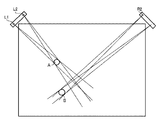
この具体例について、図32を用いて説明する。 A specific example will be described with reference to FIG.
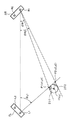
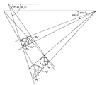
例えば、図32に示すような座標入力領域の位置に、それぞれ指示具Aと指示具Bで指示する場合、図中の受光部S2の位置の場合における指示具Aと指示具Bに対応する光量分布は、それぞれ図33(b)のA及びBのようになり、指示具Aと指示具Bの2点の遮光位置に対応した遮光影が分離して検出される。 For example, when the pointing tool A and the pointing tool B are used to indicate the position of the coordinate input area as shown in FIG. 32, respectively, the amount of light corresponding to the pointing tool A and the pointing tool B at the position of the light receiving unit S2 in the figure. The distributions are as shown in A and B of FIG. 33B, respectively, and the light shielding shadows corresponding to the two light shielding positions of the pointing tool A and the pointing tool B are detected separately.
尚、参照データとして、何も指示入力しない場合の光量分布は、図33(a)で示すようになる。この図33(a)において、Cの位置にある光量分布の谷は、座標入力領域の周囲に設けた再帰反射部材の角度特性、距離による減衰等の要因により生じた光量分布である。 As reference data, the light amount distribution when no instruction is input is as shown in FIG. In FIG. 33A, the valley of the light amount distribution at the position C is a light amount distribution caused by factors such as angular characteristics of the retroreflective member provided around the coordinate input area, attenuation due to distance, and the like.
一方、図32に示す受光部S1の場合における指示具Aと指示具Bに対応する光量分布は、図33(c)のようになり、指示具Aと指示具Bの2点の位置に対応した遮光影が重なって検出される。この重なった遮光影(遮光重なり)を有する光量分布(遮光光量分布)の情報においては、図33(c)に示すように、図33(b)のAとBが部分的に重なっている(いわゆる、部分食が発生している)場合には、それぞれの指示具の片方の遮光範囲の端部情報しか得られない。そのため、従来の遮光範囲の両端の情報からその中心、あるいは、中心の画素番号により位置(角度)を算出する方法では、指示具Aと指示具Bの座標を算出することは不可能である。 On the other hand, the light quantity distribution corresponding to the pointing tool A and the pointing tool B in the case of the light receiving unit S1 shown in FIG. 32 is as shown in FIG. 33 (c), and corresponds to the positions of two points of the pointing tool A and the pointing tool B. The shaded shadows detected are overlapped and detected. In the information of the light amount distribution (light-shielded light amount distribution) having the overlapped light-shielding shadow (light-shielding overlap), as shown in FIG. 33 (c), A and B in FIG. 33 (b) partially overlap ( In the case of so-called partial eclipse), only the edge information of one light shielding range of each indicator can be obtained. For this reason, it is impossible to calculate the coordinates of the pointing tool A and the pointing tool B by the conventional method of calculating the position (angle) from the center or the pixel number of the center from the information on both ends of the light shielding range.
また、対象受光部に対し、手前の第1指示具の影に、受光部から遠い方の第2指示具の影が完全に含まれてしまう(いわゆる、皆既食が発生している)場合にも、手前の第1指示具に関しては、その遮光影の両端から中心位置(角度)を算出することはできるが、遠い方の第2指示具に関する情報は得ることができない。 In addition, when the shadow of the first pointing tool in front of the target light receiving unit completely includes the shadow of the second pointing tool far from the light receiving unit (so-called total eclipse occurs) For the first pointing tool in front, the center position (angle) can be calculated from both ends of the shading shadow, but information on the farther second pointing tool cannot be obtained.
従って、先行例においては、複数の指示具の同時入力によって発生する遮光影の数を予め検出しておき、受光部で検出する数として、例えば、第2受光部において「2」で、第1受光部においては「1」である場合には、第1受光部において、指示具に対応する遮光影が受光部が検出する光量分布において重なっている場合とみなす。 Therefore, in the preceding example, the number of shading shadows generated by simultaneous input of a plurality of pointing tools is detected in advance, and the number detected by the light receiving unit is, for example, “2” in the second light receiving unit. When “1” in the light receiving unit, it is considered that the light shielding shadow corresponding to the pointing tool overlaps in the light amount distribution detected by the light receiving unit in the first light receiving unit.
そして、このような場合においては、特許文献6では、そのような状態の発生の旨を示す警告を発して、使用者に注意を喚起して、その状態を回避する構成としている。また、特許文献4や5では、第1受光部から、重なりの無い分離された2つの遮光影を検出できる他の第3受光部に切り替え、その2つの遮光影を検出できる受光部(この場合、第1受光部及び第3受光部)で角度を検出し、各受光部から得られる入力座標候補に対し、上述の虚実判定を施し、最終的な2点の実入力座標を決定する必要がある。
And in such a case, in patent document 6, it is set as the structure which issues the warning which shows that the occurrence of such a state, alerts a user, and avoids the state. In
尚、この場合の虚実判定は、遮光重なりを検出する受光部の角度情報でも十分に可能であるので、特許文献5や6では、この遮光重なりを検出する受光部の角度情報で行っている。 In this case, since the true / false determination can be sufficiently performed by the angle information of the light receiving unit that detects the light shielding overlap, in Patent Documents 5 and 6, the angle information of the light receiving unit that detects the light shielding overlap is used.
以上のように、遮光方式の座標入力装置では、例えば、2つの指示具を同時に入力した場合、受光部に対しほんの一部にでも遮光重なりが生じ、その2つの指示具に対応する遮光影がつながって分離できなくなった場合には、例えば、その連続した遮光影を1つの指示具からの影とみなして算出すれば、実際の位置からのずれにより座標検出精度の劣化が生じてしまう。 As described above, in the light shielding type coordinate input device, for example, when two indicators are input at the same time, even a part of the light receiving portion has a light shielding overlap, and a light shielding shadow corresponding to the two indicators is generated. In the case where the connection cannot be separated and calculated, for example, if the continuous shading shadow is calculated as a shadow from one pointing tool, the coordinate detection accuracy deteriorates due to deviation from the actual position.
一方、特許文献7においては、上記皆既食の場合と部分食の場合においても、一つの指示対象に対して各センサの遮光影から生じる複数の接線となる遮光端の角度情報の内、少なくとも3本の遮光端の角度情報から、接線の2等分線の交点として座標を算出することができるが、以下のような課題への対応が成されていない。 On the other hand, in Patent Document 7, even in the case of the total eclipse and the partial eclipse, at least three of the angle information of the light-shielding ends that become a plurality of tangent lines generated from the light-shielding shadow of each sensor with respect to one indication target. Although the coordinates can be calculated from the angle information of the light-shielding end as the intersection of the bisectors of the tangent line, the following problems are not addressed.
この種の座標入力装置においては、入力領域の周辺に複数のセンサユニットが備えられ、また、入力領域の左右上下の辺などに再帰反射部材が備えられている。各々のセンサユニットからは、再帰反射部材に向けて光が投光され、再帰反射部材で反射した光をセンサユニットで受光するように構成されている。そして、投光された光ないし反射した光が指示具によって遮られることによって形成される影を、各々のセンサユニットが検知することにより、指示具によって入力された位置をセンサユニットから見た方向を検知して、指示具が示す座標位置を検出する。このため、光を遮ることによって形成された影を、その数および位置(角度)ともに全てのセンサユニットが正確に検出しなければならない。 In this type of coordinate input device, a plurality of sensor units are provided around the input area, and retroreflective members are provided on the left, right, top, and bottom sides of the input area. Light is projected from each sensor unit toward the retroreflective member, and the light reflected by the retroreflective member is received by the sensor unit. Then, each sensor unit detects a shadow formed by the projected light or reflected light being blocked by the pointing tool, so that the direction when the position input by the pointing tool is viewed from the sensor unit is detected. The coordinate position indicated by the pointing tool is detected. For this reason, all sensor units must accurately detect the shadows formed by blocking the light, both in number and position (angle).
しかしながら、センサユニット毎の感度等の個体特性のばらつきやセンサユニット毎に投光と受光の光経路が入力領域によって異なる場合に、指示具で遮光した際に、本来は所定の複数のセンサユニットから同時に検知されるべき影が、特定のセンサユニットからは所定の位置に検知され、かつ他の特定のセンサユニットからは所定の位置に検知されるべき影が検出されないという問題が発生する可能性がある。即ち、指示具が入力面に到達して影が完全に形成されるまで(以下、この状態を「入力過渡状態」にあるという)のタイミングがセンサユニット毎に異なる場合がある。 However, if the light characteristics of the individual characteristics such as the sensitivity of each sensor unit and the light path of light projection and light reception differ for each sensor unit depending on the input area, There is a possibility that a shadow to be detected at the same time is detected at a predetermined position from a specific sensor unit, and a shadow to be detected at a predetermined position is not detected from another specific sensor unit. is there. In other words, the timing until the pointing tool reaches the input surface and a shadow is completely formed (hereinafter, this state is referred to as “input transient state”) may be different for each sensor unit.
このように、本来あるべき影を検出できなかった場合、座標を確実に検出することができなくなる。特に、この課題は複数の指示具で、同時に複数の入力を行った場合に影響が大きく、あたかも、指示具の部分重なりが生じた場合のように、各センサユニットで検出される遮光範囲の数と同一になる場合がある。また、場合によっては、本来ありえない位置に指示具が入力したかのような誤った座標を検出してしまう可能性がある。 As described above, when the desired shadow cannot be detected, the coordinates cannot be reliably detected. In particular, this problem has a large effect when multiple inputs are made simultaneously with multiple pointing tools, as if the number of light-shielding ranges detected by each sensor unit is as if the pointing tools partially overlapped. May be the same. Further, in some cases, there is a possibility that erroneous coordinates are detected as if the pointing tool has been input at a position that is not possible.
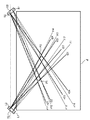
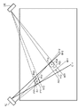
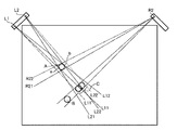
例えば、図34に示すように、いま指示具の入力がAとBの位置になされたとすると、センサS2で検出される遮光端部情報としてA11、A12、A13、A14が得られるのと同様に、センサS1においても遮光端部情報としてB11、B12、B13、B14が検出されるはずである。しかしながら、入力過渡状態の場合には、センサS1においては、遮光端部情報としてB11、B12のみが検出される場合がある。このとき、算出する座標は、遮光範囲の中心を用いて計算する場合には、Aの座標とP11の座標が検出される。また、3つの遮光端部情報を用いて2等分線の交点を計算して座標を算出する場合であっても、Aの座標とP21またはP22の座標が計算されてしまう。したがって、これらのP11、P21、P22はBの座標とは異なった位置に計算されてしまう。 For example, as shown in FIG. 34, if the input of the pointing tool is made at the positions A and B, the light shielding end information detected by the sensor S2 is obtained as A11, A12, A13, and A14. In the sensor S1, B11, B12, B13, and B14 should be detected as the light shielding edge information. However, in the case of an input transient state, in the sensor S1, only B11 and B12 may be detected as light shielding edge information. At this time, when calculating the coordinates using the center of the light shielding range, the coordinates of A and the coordinates of P11 are detected. Further, even when the coordinates are calculated by calculating the intersection of the bisectors using the three light shielding edge information, the coordinates of A and the coordinates of P21 or P22 are calculated. Therefore, these P11, P21, and P22 are calculated at positions different from the coordinates of B.
先述の特許文献1から7においては、この問題を解決する手段に関しては一切の記載がない。
In the above-mentioned
本発明は上記の課題を解決するためになされたものであり、指示具が入力領域に到達してから影が形成されるまでの状態において、誤った座標を出力することのない座標入力装置及びその制御方法、プログラムを提供することを目的とする。 The present invention has been made to solve the above problem, and a coordinate input device that does not output erroneous coordinates in a state from when the pointing tool reaches the input area until a shadow is formed, and An object is to provide a control method and a program thereof.
上記の目的を達成するための本発明による座標入力装置は以下の構成を備える。即ち、
座標入力領域上の複数の指示位置を検出する座標入力装置であって、
前記座標入力領域上に対する指示手段の有無を検出する複数の検出手段と、
前記座標入力領域上に指示がない場合の初期状態での前記複数の検出手段の初期検出信号分布に対し、指示手段により発生する信号変化範囲を特定する特定手段と、
前記特定手段で特定された信号変化範囲の端部情報を検出する端部情報検出手段と、
前記端部情報検出手段で検出された複数の端部情報を用いて、前記指示手段の指示位置の座標を算出する算出手段と、
前記複数の検出手段の1つの検出手段の検出信号における信号変化範囲が、第1の指示手段による信号変化範囲と第2の指示手段による信号変化範囲が重なった状態であるか、あるいは、前記第2の指示手段が前記座標入力領域に到達してから検出信号が変化するまでの状態であるか、判定する判定手段とを備え、
前記判定手段の判定の結果、前記第1の指示手段による信号変化範囲と第2の指示手段による信号変化範囲が重なった状態であると判定すると、前記算出手段により算出された座標を出力し、前記第2の指示手段が座標入力領域に到達してから検出信号が変化するまでの状態であると判定すると、前記算出手段により算出された座標を出力しない。
In order to achieve the above object, a coordinate input device according to the present invention comprises the following arrangement. That is,
A coordinate input device for detecting a plurality of designated positions on a coordinate input area,
A plurality of detection means for detecting the presence or absence of an instruction means on the coordinate input area;
A specifying unit that specifies a signal change range generated by the instruction unit with respect to an initial detection signal distribution of the plurality of detection units in an initial state when there is no instruction on the coordinate input area;
End information detecting means for detecting end information of the signal change range specified by the specifying means;
Calculating means for calculating the coordinates of the pointing position of the pointing means using a plurality of edge information detected by the edge information detecting means;
The signal change range in the detection signal of one detection means of the plurality of detection means is a state where the signal change range by the first instruction means overlaps the signal change range by the second instruction means, or the first change Determination means for determining whether or not the two instruction means reach the coordinate input area until the detection signal changes,
As a result of the determination by the determination unit, when it is determined that the signal change range by the first instruction unit and the signal change range by the second instruction unit overlap each other, the coordinates calculated by the calculation unit are output, If it is determined that the second instruction means has reached the coordinate input area until the detection signal changes, the coordinates calculated by the calculation means are not output.
また、好ましくは、前記判定手段は、前記複数の端部情報を用いて算出される複数の座標を比較する比較手段を備え、
前記比較手段による比較結果に基づいて、第1の指示手段による信号変化範囲と第2の指示手段による信号変化範囲が重なった状態であるか、あるいは、前記第2の指示手段が前記座標入力領域に到達してから検出信号が変化するまでの状態であるか、判定する。
Preferably, the determination unit includes a comparison unit that compares a plurality of coordinates calculated using the plurality of end information.
Based on the comparison result by the comparison means, the signal change range by the first instruction means and the signal change range by the second instruction means are overlapped, or the second instruction means is in the coordinate input area It is determined whether or not the detection signal changes after reaching.
また、好ましくは、前記複数の端部情報それぞれが示す端部の前記座標入力領域上の位置と、各端部情報に対応する前記検出手段とを結ぶ接線同士の交点座標を比較する比較手段を備え、
前記比較手段による比較結果に基づいて、第1の指示手段による信号変化範囲と第2の指示手段による信号変化範囲が重なった状態であるか、あるいは、前記第2の指示手段が前記座標入力領域に到達してから検出信号が変化するまでの状態であるか、判定する。
Preferably, the comparison means for comparing the intersection coordinates of tangents connecting the position on the coordinate input area of the end indicated by each of the plurality of end information and the detection means corresponding to each end information. Prepared,
Based on the comparison result by the comparison means, the signal change range by the first instruction means and the signal change range by the second instruction means are overlapped, or the second instruction means is in the coordinate input area It is determined whether or not the detection signal changes after reaching.
また、好ましくは、前記判定手段は、前記算出手段により算出された座標、前記指示手段の太さ、及び、前記特定手段により特定された信号変化範囲に基づいて、第1の指示手段による信号変化範囲と第2の指示手段による信号変化範囲が重なった状態であるか、あるいは、前記第2の指示手段が前記座標入力領域に到達してから検出信号が変化するまでの状態であるか、判定する。 Preferably, the determination means is a signal change by the first instruction means based on the coordinates calculated by the calculation means, the thickness of the instruction means, and the signal change range specified by the specification means. It is determined whether the range and the signal change range by the second instruction means overlap, or whether the detection signal changes after the second instruction means reaches the coordinate input area. To do.
また、好ましくは、前記判定手段は、前記端部情報検出手段で検出した信号変化範囲の端部情報が示す信号変化範囲の両端の前記検出手段に対する角度情報に基づいて、第1の指示手段による信号変化範囲と第2の指示手段による信号変化範囲が重なった状態であるか、あるいは、前記第2の指示手段が前記座標入力領域に到達してから検出信号が変化するまでの状態であるか、判定する。 Preferably, the determination means is based on angle information with respect to the detection means at both ends of the signal change range indicated by the end information of the signal change range detected by the end information detection means. Whether the signal change range overlaps with the signal change range by the second instruction means, or is the state from when the second instruction means reaches the coordinate input area until the detection signal changes. ,judge.
上記の目的を達成するための本発明による座標入力装置の制御方法は以下の構成を備える。即ち、
座標入力領域上に対する指示手段の有無を検出する検出部を備え、前記座標入力領域上の複数の指示位置を検出する座標入力装置の制御方法であって、
前記座標入力領域上に指示がない場合の初期状態での前記複数の検出部の初期検出信号分布に対し、指示手段により発生する信号変化範囲を特定する特定工程と、
前記特定工程で特定された信号変化範囲の端部情報を検出する端部情報検出工程と、
前記端部情報検出工程で検出された複数の端部情報を用いて、前記指示手段の指示位置の座標を算出する算出工程と、
前記複数の検出部の1つの検出部の検出信号における信号変化範囲が、第1の指示手段による信号変化範囲と第2の指示手段による信号変化範囲が重なった状態であるか、あるいは、前記第2の指示手段が前記座標入力領域に到達してから検出信号が変化するまでの状態であるか、判定する判定工程とを備え、
前記判定工程の判定の結果、前記第1の指示手段による信号変化範囲と第2の指示手段による信号変化範囲が重なった状態であると判定すると、前記算出工程により算出された座標を出力し、前記第2の指示手段が座標入力領域に到達してから検出信号が変化するまでの状態であると判定すると、前記算出工程により算出された座標を出力しない。
In order to achieve the above object, a method for controlling a coordinate input device according to the present invention comprises the following arrangement. That is,
A control method for a coordinate input device that includes a detection unit that detects the presence or absence of an instruction unit on a coordinate input area, and detects a plurality of indicated positions on the coordinate input area,
A specifying step of specifying a signal change range generated by the instruction means for the initial detection signal distribution of the plurality of detection units in an initial state when there is no instruction on the coordinate input area;
An end information detecting step of detecting end information of the signal change range specified in the specifying step;
A calculation step of calculating coordinates of an indication position of the indication means using a plurality of edge information detected in the edge information detection step;
The signal change range in the detection signal of one detection unit of the plurality of detection units is a state in which the signal change range by the first instruction unit overlaps the signal change range by the second instruction unit, or A determination step of determining whether or not the two instruction means have reached the coordinate input area until the detection signal changes.
As a result of the determination in the determination step, when it is determined that the signal change range by the first instruction unit and the signal change range by the second instruction unit overlap each other, the coordinates calculated by the calculation step are output, If it is determined that the second instruction means has reached the coordinate input area until the detection signal changes, the coordinates calculated by the calculation step are not output.
上記の目的を達成するための本発明によるプログラムは以下の構成を備える。即ち、
座標入力領域上に対する指示手段の有無を検出する複数の検出手段を備え、前記座標入力領域上の複数の指示位置を検出する座標入力装置として、コンピュータを機能させるためのプログラムであって、
前記座標入力領域上に指示がない場合の初期状態での前記複数の検出手段の初期検出信号分布に対し、指示手段により発生する信号変化範囲を特定する特定手段と、
前記特定手段で特定された信号変化範囲の端部情報を検出する端部情報検出手段と、
前記端部情報検出手段で検出された複数の端部情報を用いて、前記指示手段の指示位置の座標を算出する算出手段と、
前記複数の検出手段の1つの検出手段の検出信号における信号変化範囲が、第1の指示手段による信号変化範囲と第2の指示手段による信号変化範囲が重なった状態であるか、あるいは、前記第2の指示手段が前記座標入力領域に到達してから検出信号が変化するまでの状態であるか、判定する判定手段として、コンピュータを機能させ、
前記判定手段の判定の結果、前記第1の指示手段による信号変化範囲と第2の指示手段による信号変化範囲が重なった状態であると判定すると、前記算出手段により算出された座標を出力し、前記第2の指示手段が座標入力領域に到達してから検出信号が変化するまでの状態であると判定すると、前記算出手段により算出された座標を出力しない。
In order to achieve the above object, a program according to the present invention comprises the following arrangement. That is,
A program for causing a computer to function as a coordinate input device that includes a plurality of detection means for detecting the presence or absence of an instruction means on a coordinate input area and detects a plurality of indicated positions on the coordinate input area,
A specifying unit that specifies a signal change range generated by the instruction unit with respect to an initial detection signal distribution of the plurality of detection units in an initial state when there is no instruction on the coordinate input area;
End information detecting means for detecting end information of the signal change range specified by the specifying means;
Calculating means for calculating the coordinates of the pointing position of the pointing means using a plurality of edge information detected by the edge information detecting means;
The signal change range in the detection signal of one detection means of the plurality of detection means is a state where the signal change range by the first instruction means overlaps the signal change range by the second instruction means, or the
As a result of the determination by the determination unit, when it is determined that the signal change range by the first instruction unit and the signal change range by the second instruction unit overlap each other, the coordinates calculated by the calculation unit are output, If it is determined that the second instruction means has reached the coordinate input area until the detection signal changes, the coordinates calculated by the calculation means are not output.
本発明によれば、指示手段が座標入力領域に到達してから検出信号が変化するまでの状態において、誤った座標を出力することのない座標入力装置及びその制御方法、プログラムを提供できる。 According to the present invention, it is possible to provide a coordinate input device that does not output erroneous coordinates, a control method thereof, and a program in a state from when the instruction means reaches the coordinate input area until the detection signal changes.
以下、本発明の実施の形態について図面を用いて詳細に説明する。
<<実施形態1>>
<装置構成の概略説明>
まず、図1を用いて、座標入力装置全体の概略構成を説明する。
Hereinafter, embodiments of the present invention will be described in detail with reference to the drawings.
<<
<Overview of device configuration>
First, the overall configuration of the coordinate input device will be described with reference to FIG.
図1は本発明の実施形態1の遮光方式の座標入力装置の概略構成を示す図である。 FIG. 1 is a diagram showing a schematic configuration of a light-shielding coordinate input device according to a first embodiment of the present invention.
図1において、1L、1Rは投光部および受光部を有するセンサユニットであり、実施形態1の場合、図示の如く座標入力面であるところの座標入力有効領域3のX軸に平行に、かつY軸に対称な位置に、所定距離離れて配置されている。センサユニット1L及び1Rは、制御・演算ユニット2に接続され、制御信号を制御・演算ユニット2から受信すると共に、検出した信号を制御・演算ユニット2に送信する。
In FIG. 1, 1L and 1R are sensor units having a light projecting unit and a light receiving unit. In the case of the first embodiment, as shown in FIG. 1, parallel to the X axis of the coordinate input
4は入射光を到来方向に反射する再帰反射面を有する再帰反射部であり、座標入力有効領域3の外側3辺に図示が如く配置され、左右それぞれのセンサユニット1L及び1Rから略90°範囲に投光された光を、センサユニット1L及び1Rに向けて再帰反射する。
尚、再帰反射部4は、ミクロ的に見て3次元的な構造を有し、現在では、主にビーズタイプの再帰反射テープ、或いはコーナキューブを機械加工等により規則正しく配列することで再帰現象を起こす再帰反射テープが知られている。
The
再帰反射部4で再帰反射された光は、センサユニット1L及び1Rによって1次元的に検出され、その光量分布が制御・演算ユニット2に送信される。
The light retroreflected by the
座標入力有効領域3は、PDPやリアプロジェクタ、LCDパネルなどの表示装置の表示画面で構成することで、インタラクティブな入力装置として、利用可能となっている。
The coordinate input
このような構成において、座標入力有効領域3に指や指示具等の指示手段による入力指示がなされると、センサユニット1L及び1Rの投光部から投光された光が遮られ(遮光部分)、センサユニット1L及び1Rの受光部ではその遮光部分の光(再帰反射による反射光)を検出できないので、その結果、どの方向からの光が検出できなかったかを判別することが可能となる。
In such a configuration, when an input instruction is given to the coordinate input
そこで、制御・演算ユニット2は、左右のセンサユニット1L及び1Rが検出する光量変化から、指示具によって入力指示された部分の複数の遮光範囲を検出し、その遮光範囲の端部情報から、センサユニット1L及び1Rそれぞれに対する遮光範囲の端部の方向(角度)をそれぞれ算出する。また、指示具が信号発信部を有する場合には、その指示具からのペン信号をペン信号受信部5が受信する。
Therefore, the control /
そして、検出された遮光範囲の数に基づいて、座標算出に用いる遮光範囲から得られるデータを決定し、それぞれ算出された方向(角度)、及びセンサユニット1L及び1R間の距離情報等から、座標入力有効領域3上の指示具の遮光位置を幾何学的に算出し、表示装置に接続されているホストコンピュータ等の外部端末に、インタフェース7(例えば、USB、IEEE1394等)を経由してその座標値を出力する。
Then, based on the number of detected light-shielding ranges, data obtained from the light-shielding ranges used for coordinate calculation is determined, and coordinates are calculated from the calculated direction (angle), distance information between the
このようにして、指示具によって、画面上に線を描画したり、表示装置に表示されるアイコンを操作する等の外部端末の操作が可能になる。 In this way, the operation of the external terminal such as drawing a line on the screen or operating an icon displayed on the display device can be performed by the pointing tool.
<センサユニット1の詳細説明>
次に、センサユニット1L及び1R内の構成について、図2を用いて説明する。尚、センサユニット1L及び1Rは、大きく分けて投光部と受光部から構成される。
<Detailed description of
Next, the configuration in the
図2は本発明の実施形態1のセンサユニットの詳細構成を示す図である。 FIG. 2 is a diagram showing a detailed configuration of the sensor unit according to the first embodiment of the present invention.
図2において、101A及び101Bは、赤外光を発する赤外LEDであり、各々投光レンズ102A及び102Bによって、再帰反射部4に向けて略90°範囲に光を投光する。ここで、センサユニット1L及び1R中の投光部は、この赤外LED101A及び101Bと、投光レンズ102A及び102Bによって実現される。これにより、センサユニット1L及び1Rには、それぞれ2つの投光部が構成されることになる。
In FIG. 2, 101A and 101B are infrared LEDs that emit infrared light, and project light in a range of approximately 90 ° toward the
そして、投光部より投光された赤外光は、再帰反射部4により到来方向に再帰反射され、センサユニット1L及び1R中の受光部によって、その光を検出する。
Then, the infrared light projected from the light projecting unit is retroreflected in the arrival direction by the
受光部は、光線の視野を制限すると共に電気的なシールドをになうシールド部材105を設けた1次元のラインCCD104、集光光学系としての受光用レンズ106A及び106B、入射光の入射方向を概略制限する絞り108A及び108B、及び可視光等の余分な光(外乱光)の入射を防止する赤外フィルター107A及び107Bからなる。
The light receiving unit restricts the field of view of the light and provides a one-
そして、再帰反射部4によって反射された光は、赤外フィルター107A及び107B、絞り108A及び108Bを抜けて受光用レンズ106A及び106Bによって、ラインCCD104の検出素子110面上に集光される。これにより、センサユニット1L及び1Rには、それぞれ2つの受光部が構成されることになる。
The light reflected by the
部材103及び部材109は、投光部及び受光部を構成する光学部品を配置するとともに、投光部で投光した光が直接受光部に入射することを防ぐ、あるいは外来光をカットするための上フード103、下フード109として機能する。
The
尚、実施形態1においては、絞り108A及び108Bは下フード109に一体で成型されているが、別部品であってもよいことはいうまでもなく、さらには、上フード103側に、絞り108A及び108Bと受光用レンズ106A及び106Bの位置決め部を設けることで、投光部の発光中心に対する受光部の位置決めを容易にする構成(つまり、上フード103のみで、すべての主要な光学部品が配置される構成)に実現することも可能である。
In the first embodiment, the
図3Aは、図2の状態のセンサユニット1L(1R)を組み上げた状態を、正面方向(座標入力面に対し垂直方向)から見た図である。図3Aに示すように、センサユニット1L(1R)中の2つの投光部は、所定距離d離れた状態で、それぞれの主光線方向が略平行となるように配置され、各々の投光レンズ102A及び102Bによって、それぞれ略90°範囲に光を投光するように構成している。
3A is a view of the assembled state of the
図3Bは、図3Aの太矢印で示される部分の断面図であり、赤外LED101A(101B)からの光は、投光レンズ102A(102B)により、座標入力面に略平行に制限された光束として、主に再帰反射部4に対して光が投光されるように構成している。
FIG. 3B is a cross-sectional view of the portion indicated by the thick arrow in FIG. 3A, and the light from the
一方、図3Cは、図3Aにおける赤外LED101A及び101B、投光レンズ102A及び102B、上フード103を取り除いた状態を、正面方向(座標入力面に対し垂直方向)から見た図である。
On the other hand, FIG. 3C is a view of the state in which the
ここで、実施形態1の場合、投光部と受光部は、座標入力面である座標入力有効領域3の垂直方向に対し重ねた配置構成(図3B参照)となっており、正面方向(座標入力面に対し垂直方向)から見て、投光部の発光中心と受光部の基準位置(つまり、角度を計測するための基準点位置に相当し、実施形態1にあっては絞り108A(108B)の位置であって、図中の光線が交差する点となる)が一致する構造となっている。
Here, in the case of the first embodiment, the light projecting unit and the light receiving unit have an arrangement configuration (see FIG. 3B) that overlaps the vertical direction of the coordinate input
従って、前述した通り、2つの投光部は所定距離d離れた状態で、それぞれの主光線方向略平行となるように配置されているので、2つの受光部も同様に所定距離d離れた状態で、かつ各々の光軸(光学的な対称軸)が略平行となるように構成されている。 Therefore, as described above, since the two light projecting portions are arranged so as to be substantially parallel to each other in the principal ray direction with a predetermined distance d apart, the two light receiving portions are similarly separated by the predetermined distance d. And each optical axis (optical symmetry axis) is substantially parallel.
また、投光部により投光された座標入力面に略平行な光束であって、面内方向に略90°方向に投光されている光は、再帰反射部4により光の到来方向に再帰反射され、赤外フィルター107A(107B)、絞り108A(108B)、集光レンズ106A(106B)を経て、ラインCCD104の検出素子110面上に集光、結像することになる。
In addition, light that is approximately parallel to the coordinate input surface projected by the light projecting unit and is projected in a direction of approximately 90 ° in the in-plane direction is recursed in the light arrival direction by the
従って、ラインCCD104の出力信号は、反射光の入射角に応じた光量分布を出力することになるので、ラインCCD104を構成する各画素の画素番号が角度情報を示すことになる。
Accordingly, since the output signal of the
尚、図3Bに示す投光部と受光部の距離Lは、投光部から再帰反射部4までの距離に比べて十分に小さな値であり、距離Lを有していても十分な再帰反射光を受光部で検出することが可能な構成となっている。
Note that the distance L between the light projecting unit and the light receiving unit shown in FIG. 3B is sufficiently smaller than the distance from the light projecting unit to the
以上説明したように、センサユニット1L(1R)は、少なくとも2つの投光部と、各々の投光部で投光された光を各々検出する2つの受光部(実施形態1の場合、投光部が2組、受光部が2組)を有する構成である。
As described above, the
また、実施形態1にあっては、受光部の一部であるラインCCD104におけるライン状に配置された検出素子110の左側部分を第1受光部の集光領域、右側部分を第2受光部の集光領域とすることで、部品の共通化を図っているが、これに限定されるものでなく、各受光部毎に個別にラインCCDを設けてもよいことは言うまでもない。
Further, in the first embodiment, the left side portion of the
<制御・演算ユニットの説明>
制御・演算ユニット2とセンサユニット1L及び1Rの間では、主に、受光部内のラインCCD104用のCCD制御信号、CCD用クロック信号と出力信号、及び投光部内の赤外LED101A及び101Bの駆動信号がやり取りされている。
<Description of control / arithmetic unit>
Between the control /
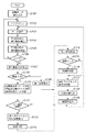
ここで、制御・演算ユニット2の詳細構成について、図4を用いて説明する。
Here, a detailed configuration of the control /
図4は本発明の実施形態1の制御・演算ユニットの詳細構成を示すブロック図である。 FIG. 4 is a block diagram showing a detailed configuration of the control / arithmetic unit according to the first embodiment of the present invention.
CCD制御信号は、ワンチップマイコン等で構成される演算制御回路(CPU)21から出力され、ラインCCD104のシャッタタイミングやデータの出力制御等が行われる。
The CCD control signal is output from an arithmetic control circuit (CPU) 21 constituted by a one-chip microcomputer or the like, and shutter timing of the
尚、この演算制御回路21は、クロック発生回路(CLK)22からのクロック信号に従って動作する。また、CCD用のクロック信号は、クロック発生回路(CLK)22からセンサユニット1L及び1Rに送信されると共に、各センサユニット内部のラインCCD104との同期をとって各種制御を行うために、演算制御回路21にも入力されている。
The
投光部の赤外LED101A及び101Bを駆動するためのLED駆動信号は、演算制御回路21からLED駆動回路(不図示)を介して、対応するセンサユニット1L及び1Rの投光部内の赤外LED101A及び101Bに供給されている。
The LED drive signal for driving the
センサユニット1L及び1Rそれぞれの受光部内のラインCCD104からの検出信号は、A/Dコンバータ23に入力され、演算制御回路21からの制御によって、デジタル値に変換される。この変換されたデジタル値は、メモリ132に記憶され、指示具の角度計算に用いられる。そして、この計算された角度から座標値が算出され、外部端末にシリアルインタフェース7(例えば、USB、IEEE1394、RS232Cインタフェース等)を介して出力される。
Detection signals from the
また、指示具としてペンを用いる場合、ペンからのペン信号を受信するペン信号受信部5からは、ペン信号を復調したデジタル信号が出力され、ペン信号検出回路としてのサブCPU24に入力され、ペン信号が解析された後、その解析結果が演算制御回路21に出力される。
When a pen is used as the pointing tool, a digital signal obtained by demodulating the pen signal is output from the pen signal receiving unit 5 that receives the pen signal from the pen, and is input to the
<光量分布検出の説明>
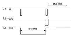
図5は本発明の実施形態1の制御信号のタイミングチャートである。
<Explanation of light intensity distribution detection>
FIG. 5 is a timing chart of control signals according to the first embodiment of the present invention.
特に、図5では、センサユニット1L(1R)中の一つの受光部およびそれに対応する照明としての赤外LED101A(101B)への制御信号のタイミングチャートを示している。
In particular, FIG. 5 shows a timing chart of control signals to one light receiving portion in the
71、72はCCD制御用の制御信号であり、SH信号71の間隔で、ラインCCD104のシャッタ開放時間が決定される。ICG信号72はセンサユニット1L(1R)へのゲート信号であり、内部のラインCCD104の光電変換部の電荷を読出部へ転送する信号である。
71 and 72 are control signals for CCD control, and the shutter opening time of the
73は赤外LED101A(101B)の駆動信号であり、ここで、SH信号71の周期で、赤外LED101A(101B)を点灯するために、LED信号73が赤外LED101A(101B)に供給される。
そして、センサユニット1L及び1Rの双方の投光部の駆動が終了した後に、センサユニット1L及び1Rの双方の受光部(ラインCCD104)の検出信号が読み出される。
Then, after the driving of the light projecting units of both the
ここで、センサユニット1L及び1Rの双方から読み出される検出信号は、座標入力有効領域3への指示具による入力がない場合には、それぞれのセンサユニットからの出力として、図6のような光量分布が得られる。もちろん、このような光量分布がどのシステムでも必ず得られるわけではなく、再帰反射部4の再帰反射特性や投光部の特性、また、経時変化(反射面の汚れなど)によって、光量分布は変化する。
Here, the detection signals read from both of the
図6においては、レベルAが最大光量であり、レベルBが最低光量となっている。 In FIG. 6, level A is the maximum light amount and level B is the minimum light amount.
つまり、再帰反射部4からの反射光がない状態では、センサユニット1L及び1Rで得られる光量レベルがレベルB付近になり、反射光量が増えるほど、レベルAに光量レベルが遷移する。このようにして、センサユニット1L及び1Rから出力された検出信号は、逐次、対応するA/Dコンバータ23でA/D変換され、演算制御回路21にデジタルデータとして取り込まれる。
That is, in a state where there is no reflected light from the
これに対し、座標入力有効領域3への指示具による入力がある場合には、センサユニット1L及び1Rからの出力として、図7のような光量分布が得られる。
On the other hand, when there is an input to the coordinate input
この光量分布のC1及びC2部分では、指示具によって再帰反射部4からの反射光が遮られているため、その部分(遮光範囲)のみ反射光量が低下していることがわかる。特に、図7では、複数の指示具によって、指示具によって再帰反射部4からの反射光が遮られているため、複数の遮光範囲が検出される。
In the C1 and C2 portions of this light amount distribution, the reflected light from the
そして、実施形態1では、指示具による入力がない場合の図6の光量分布と、指示具による入力がある場合の図7の光量分布の変化に基づいて、センサユニット1L及び1Rに対する指示具の角度を算出する。
And in
具体的には、図6の光量分布として、投光部による投光(照明)がない状態の光量分布81と、投光(照明)中で指示具による入力がない(遮蔽物がない状態)状態の光量分布82を初期状態として予めメモリ132に記憶しておく。
Specifically, as the light quantity distribution in FIG. 6, there is no
そして、センサユニット1L及び1Rそれぞれの検出信号のサンプル期間に、図7のような光量分布の変化があるか否かを、そのサンプル期間中の光量分布と、メモリ132に記憶されている初期状態の光量分布との差分によって検出する。そして、光量分布に変化がある場合には、その変化部分を指示具の入力点として、その入力角度を決定する(遮光範囲の端部を決定する)演算を行う。
Then, whether or not there is a change in the light amount distribution as shown in FIG. 7 in the sample period of the detection signals of the
上述したように、本願発明では、1つのラインCCD104に対して、複数の受光部が設けられ、その各々に対して投光部が設けられている。従って、各々の受光部(もしくは投光部)を別のタイミングで駆動する場合には、各々を上記のような信号タイミングで駆動すればよい。
As described above, in the present invention, a plurality of light receiving portions are provided for one
図8はその信号のタイミングチャート例であり、まず、センサユニット1L中のラインCCD104の読出先頭側で、センサユニット1L中の一方の受光部による検出を行うために、信号SH61に対して、信号63のようなタイミングで、赤外LED(例えば、赤外LED101A)が駆動される。信号ICG62によって、ラインCCD104の信号が読み出されるが、このときは、ラインCCDの先頭側の受光範囲の画素データが読み出される(信号65中のA部分)。
FIG. 8 is an example of a timing chart of the signal. First, in order to perform detection by one light receiving unit in the
次に、同じ、ラインCCD104に対して、SH信号61が与えられ、センサユニット1L中の他方の受光部により検出を行うために、赤外LED(例えば、赤外LED101B)に駆動信号64が供給される。この出力は、信号65のB部分のように、先に検出した先頭部分の信号(破線部)と重ならない領域に、受光された信号が出力される。
Next, the
別のタイミングで、もう一方のセンサユニット1Rを同様に駆動することで、CCDの信号が各々のセンサから読み出され、本願発明では、最大4つの受光部による検出信号を取得することになる。
By driving the
尚、実施形態1では、左右のセンサユニット1L及び1Rで合わせて4つの受光部に対して、別々のタイミングで駆動しているが、これに限定されるものではなく、お互いの発光が影響しないのであれば、同時に駆動してもかまわないし、各々の任意の組み合わせで駆動してもかまわない。
In the first embodiment, the left and
<角度計算出の説明>
センサユニット1L及び1Rに対する指示具の角度計算にあたっては、まず、指示具による遮光範囲を検出する必要がある。
<Explanation of angle calculation>
In calculating the angle of the pointing tool with respect to the
以下、センサユニット1L及び1Rの一方(例えば、センサユニット1L)による指示具の角度計算について説明するが、他方(センサユニット1R)でも同様の角度計算を行うことは言うまでもない。
Hereinafter, although the angle calculation of the pointing tool by one of the
電源投入時の光量分布として、図6の信号81及び信号82をメモリ132に記憶しておき、その信号と、実際の指示具による入力によって得られる光量分布との比較から、指示具の入力範囲(遮光範囲)を検出する。
The
図7のように、C1、C2を有する光量分布からなる入力がある場合は、その光量分布と、メモリ132に記憶されている光量分布82との差を計算し、その計算結果と、光量分布82と光量分布81の光量差を用いて、遮光(入力)がない場合との光量変化率を計算する。このように、光量変化率を計算することによって、部分的な光量分布の不均一等の影響を除去できる。
As shown in FIG. 7, when there is an input consisting of a light amount distribution having C1 and C2, the difference between the light amount distribution and the
計算された光量変化率に対して、閾値を用いて、光量が変化しているラインCCD104上の画素番号を特定する。この時、検出信号レベルの情報等を用いることで、画素番号より細かい画素情報が特定可能になる。これらの画素番号から、遮光範囲の端部を決定でき、例えば、その遮光範囲の中央値(ラインCCD104の画素番号)を指示具の角度情報として導出する。
The pixel number on the
得られた画素番号から、実際の座標値を計算するためには、角度情報(θ)に変換する必要がある。角度情報への変換は、例えば、多項式を用いて実現することができる。例えば、CCD画素番号をe、次数をn、各次数の係数をTnとすると、角度θは、
θ =Tn・en+T(n-1)・e(n-1)+T(n-2)・e(n-2)+、・・・、+T0
(1)
のようにして、算出することができる。
In order to calculate an actual coordinate value from the obtained pixel number, it is necessary to convert it into angle information (θ). The conversion into angle information can be realized using, for example, a polynomial. For example, if the CCD pixel number is e, the order is n, and the coefficient of each order is Tn, the angle θ is
θ = Tn · e n + T (n-1) · e (n-1) + T (n-2) · e (n-2) +, ..., + T0
(1)
In this way, it can be calculated.
尚、各次数の係数は、実測値や設計値等から決定できる。また、次数は必要とされる座標精度等を鑑みて決定すれば良い。 The coefficient of each order can be determined from an actual measurement value, a design value, or the like. The order may be determined in view of the required coordinate accuracy and the like.
前述の通り、センサユニット1Lには、2つの受光部が構成されていて、それぞれをL1、L2とすると、まず、受光部L1、即ち、図8のA部分の光量分布が検出される受光部について前述の遮光範囲の端部を決定する処理が実行される。このA部分については、メモリ132に格納されているA部分に対応する全てのデータについて、光量分布の差と変化率の計算処理が行なわれる。
As described above, the
そして、受光部L2に対応するB部分の光量分布については、処理時間を短縮するためにメモリ132に格納されているB部分に対応する全てのデータについて上記の計算処理を行わない。この場合、A部分の遮光範囲探索結果から、遮光範囲探索を実行するサーチ範囲を限定するように決定し、そのサーチ範囲内でA部分の遮光範囲探索処理と同様の計算処理によって遮光範囲の端部に相当するCCD画素番号を決定し、角度情報を算出する。
And about the light quantity distribution of B part corresponding to the light-receiving part L2, in order to shorten processing time, said calculation process is not performed about all the data corresponding to B part stored in the
いま、図9のように、2点の入力としてP1及びP2がある場合に、図8のA部分の光量分布に相当するセンサユニット1Lの受光部L1では、図10(a)に示すように、遮光範囲が2個検出される。この光量分布データは、図9に示すように受光部L1で検出される遮光範囲端部情報として、上述の計算処理により、l11、l12、l13、l14として検出される。同様に、センサユニット1Rの受光部R1では、図10(b)に示すように、r11、r12、r13、r14が検出される。
As shown in FIG. 10 (a), when the light receiving unit L1 of the
先述したとおり、センサユニット1L及び1Rでは、同一ラインCCD上に所定の距離離して2系統の光学系を構成している。従って、受光部L1で検出される遮光範囲端部情報から受光部L2で検出される遮光範囲の端部情報を予測することができる。即ち、上述の処理で決定したCCD画素番号から開始点を決定し、A部分の遮光範囲探索処理と同様の計算処理によってB部分の遮光範囲の端部、即ち、図9におけるl21、l22、l23、l24(図10(c))に相当するCCD画素番号を決定し、角度情報を算出することができる。
As described above, in the
同様な、遮光範囲探索処理を受光部R2についても行い、r21、r22、r23、r24(図10(d))に相当するCCD画素番号を決定し、角度情報を算出する。このようにして、複数の入力点P1及びP2の座標を算出するための遮光端部の角度情報を検出することができる。 A similar light shielding range search process is also performed for the light receiving unit R2, and CCD pixel numbers corresponding to r21, r22, r23, r24 (FIG. 10D) are determined, and angle information is calculated. In this manner, the angle information of the light shielding end for calculating the coordinates of the plurality of input points P1 and P2 can be detected.
尚、遮光範囲探索開始点を決定してから、上述の処理では、2つの遮光範囲端部を検出するまで連続して遮光範囲探索処理を行ったが、受光部L1とL2、及び受光部R1とR2で検出される遮光範囲は略等しいので、遮光範囲の端部を1つ検出したならば、所定画素数分(受光部L1及びR1の各々の遮光範囲の端部から算出する幅情報)のデータをスキップして、再び、遮光範囲探索処理を開始してもよい。この処理は、特に、センサユニットに対して入力点の距離が比較的近く、遮光範囲が大きくなる場合に有効となる。 In addition, after determining the light shielding range search start point, in the above-described processing, the light shielding range search processing is continuously performed until the two light shielding range end portions are detected, but the light receiving portions L1 and L2 and the light receiving portion R1 are performed. And R2 are substantially equal to each other. Therefore, if one end of the light shielding range is detected, a predetermined number of pixels (width information calculated from the end of each light shielding range of the light receiving portions L1 and R1). May be skipped, and the light shielding range search process may be started again. This process is particularly effective when the distance between the input points is relatively close to the sensor unit and the light shielding range becomes large.
次に、図11と図12を用いて、受光部L1で検出される遮光範囲が入力点P1とP2が重なって1つの遮光範囲として見える、「部分食」状態となっている場合について説明する。 Next, a case where the light shielding range detected by the light receiving unit L1 is in a “partial eclipse” state where the input points P1 and P2 overlap and can be seen as one light shielding range will be described with reference to FIGS. .
この場合は、受光部L1で検出される遮光範囲は1個であるので、まず、遮光範囲の端部であるl11とl12(図12(a))に相当するCCD画素番号を決定し、角度情報を算出する。次に、このl11とl12を用いて、L2の遮光範囲探索開始点を決定し、L2で検出される遮光範囲の端部であるl21とl22(図12(b))に相当するCCD画素番号を決定し、角度情報を算出する。 In this case, since there is only one light shielding range detected by the light receiving unit L1, first, CCD pixel numbers corresponding to l11 and l12 (FIG. 12 (a)) that are ends of the light shielding range are determined, and the angle Calculate information. Next, by using these l11 and l12, the L2 light shielding range search start point is determined, and the CCD pixel numbers corresponding to l21 and l22 (FIG. 12 (b)) which are the ends of the light shielding range detected at L2. And angle information is calculated.
そして、受光部R1及びR2に関しても、同様に、受光部R1における遮光範囲の端部である、r11、r12、r13、r14(図12(c))に相当するCCD画素番号を決定して、角度情報を算出する。また、受光部R2の遮光範囲探索開始点を決定し、受光部R2における遮光範囲の端部である、r21、r22、r23、r24(図12(d))に相当するCCD画素番号を決定し、角度情報を算出する。 Similarly, regarding the light receiving portions R1 and R2, CCD pixel numbers corresponding to r11, r12, r13, and r14 (FIG. 12C), which are the end portions of the light shielding range in the light receiving portion R1, are determined. Calculate angle information. Further, the light-blocking range search start point of the light-receiving unit R2 is determined, and the CCD pixel numbers corresponding to r21, r22, r23, and r24 (FIG. 12D), which are the end portions of the light-blocking range in the light-receiving unit R2, are determined. Calculate the angle information.
尚、遮光範囲探索処理の処理順序は、まず、受光部L1、次に、受光部L2として、CCDの読出順としたが、これに限定されるものではない。例えば、2つの受光部において、一方が座標入力有効領域の全域について受光可能で、もう一方は補助的に座標入力有効領域の限定した領域について受光可能な構成である場合には、座標入力有効領域全域について受光可能な受光部のデータから遮光範囲探索処理を行ってもよい。この場合は、単1点入力を主な使い方とする場合に、座標入力有効領域全域について受光可能な受光部のデータのみを遮光範囲探索処理する構成をとることができるので、サンプリング速度に有利な構成となる。 Note that the processing order of the light shielding range search processing is first the CCD reading order as the light receiving unit L1, and then the light receiving unit L2, but is not limited thereto. For example, in two light receiving units, one is capable of receiving light for the entire coordinate input effective region, and the other is configured to receive light for an auxiliary region limited to the coordinate input effective region. The light-shielding range search process may be performed from data of a light-receiving unit that can receive light over the entire area. In this case, when single point input is mainly used, it is possible to adopt a configuration in which only the data of the light receiving unit capable of receiving light in the entire coordinate input effective region can be searched, and this is advantageous for the sampling speed. It becomes composition.
<座標算出方法の説明>
次に、画素番号から変換された角度情報(θ)から、指示具の位置座標を算出する座標算出方法について説明する。
<Description of coordinate calculation method>
Next, a coordinate calculation method for calculating the position coordinates of the pointing tool from the angle information (θ) converted from the pixel number will be described.
尚、指示具の入力が1点である場合には、センサユニット1L及び1Rの出力結果に基づいて得られる遮光範囲の中央の角度を用いることで座標算出が可能である。
When the input of the pointing tool is one point, coordinates can be calculated by using the center angle of the light shielding range obtained based on the output results of the
ここで、座標入力有効領域3上に定義する座標とセンサユニット1L及び1Lとの位置関係及び座標系について、図13を用いて説明する。
Here, the positional relationship between the coordinates defined on the coordinate input
図13は本発明の実施形態1の座標入力有効領域上に定義する座標とセンサユニット1L及び1Lとの位置関係を示す図である。
FIG. 13 is a diagram showing the positional relationship between the coordinates defined on the coordinate input effective area and the
図13では、座標入力有効領域3の水平方向にX軸、垂直方向にY軸を定義し、座標入力有効領域3の中央を原点位置O(0,0)に定義している。そして、座標入力有効領域3の座標入力範囲の上辺左右に、それぞれのセンサユニット1L及び1RをY軸に対称に取り付け、その間の距離はDLRである。
In FIG. 13, the X axis is defined in the horizontal direction and the Y axis is defined in the vertical direction of the coordinate input
また、センサユニット1L及び1Rそれぞれの受光面は、その法線方向がX軸と45度の角度を成すように配置され、その法線方向を0度と定義している。
The light receiving surfaces of the
この時、角度の符号は、左側に配置されたセンサユニット1Lの場合には、時計回りの方向を『+』方向に、また、右側に配置されたセンサユニット1Rの場合には、反時計回りの方向を『+』方向と定義している。
At this time, the sign of the angle is the clockwise direction in the case of the
さらには、P0はセンサユニット1L及び1Rの法線方向の交点位置、つまり、基準角度の交点となる。また、センサユニット1L(1R)の位置から原点までのY座標距離をDYとする。この時、基準角度から、それぞれのセンサユニット1L及び1Rで得られた角度をθL、θRとすると、検出すべき点Pの座標P(x,y)は、tanθL、tanθRを用いて、
x = DLR/2 * (tanθL+ tanθR) / (1+( tanθL * tanθR) ) (2)
y = DLR/2* ((1+tanθL)(1+ tanθR)) / (1+( tanθL * tanθR))-DY (3)
で計算される。
Furthermore, P0 is the intersection position of the
x = DLR / 2 * (tanθL + tanθR) / (1+ (tanθL * tanθR)) (2)
y = DLR / 2 * ((1 + tanθL) (1+ tanθR)) / (1+ (tanθL * tanθR))-DY (3)
Calculated by
ここでの、角度データのとり方は、基準角度からの角度としている。これは、このように角度を設定することで、tanθのとる値が±π/4の範囲にあるため、座標算出が不安定にならないという効果がある。他の算出において、θの値がπ/2値をとっても、不安定ならないようであれば、同一高さ(同一レベル)にある、受光部を結ぶラインに対する角度を用いて、算出を行っても良い。例えば、以下に示す補正計算に関しては、そのような角度定義で計算することができる。 Here, the angle data is taken from the reference angle. By setting the angle in this way, there is an effect that coordinate calculation does not become unstable because the value taken by tan θ is in the range of ± π / 4. In other calculations, even if the value of θ takes a value of π / 2, if it does not become unstable, the calculation may be performed using the angle with respect to the line connecting the light receiving parts at the same height (same level). good. For example, the correction calculation shown below can be calculated with such an angle definition.
ここで、各センサユニット1L(R)の2つの受光部は、実際には座標入力領域に対して同一ライン上には設けられていない。そのため、座標算出時に、異なる位置の受光部のデータを用いる場合には、この位置のずれ分の補正を行う必要がある。
Here, the two light receiving portions of each
図14に示すように、センサユニット1Lの2つの受光部の瞳位置をそれぞれL1及びL2、センサユニット1Rの2つの受光部の瞳位置をそれぞれR1、R2とする。また、L1とL2とのx軸方向の差であるx軸方向距離Δxs、L1とL2とのy軸方向の差であるy軸方向距離Δysとする。
As shown in FIG. 14, the pupil positions of the two light receiving portions of the
L2で検出されたデータがθL2である場合、X軸方向にR1と同一高さで見ると、仮想的にVL2の位置にセンサユニット1Lがあるとして、ΔvxsをθL2を用いて算出することができる。
When the data detected at L2 is θL2, when viewed at the same height as R1 in the X-axis direction, Δvxs can be calculated using θL2 assuming that the
そして、R1と同一高さに換算するには、高さ方向の距離Δysと得られた角度θL2とから、
Δvxs=Δys/tanθL2
となる。
And in order to convert to the same height as R1, from the distance Δys in the height direction and the obtained angle θL2,
Δvxs = Δys / tan θL2
It becomes.
よって、式(2)、(3)のセンサユニット間距離DLRを、受光部の瞳位置L1及びL2間のX方向距離Δxsと、算出されたΔvxsで補正し、仮の座標値を計算することが可能となる。計算されたこの仮の座標値におけるx座標は、VL2とR1の中間を原点として計算されるので、そのX座標から(Δxs+Δvxs)/2をさらに補正すれば、異なる位置にある受光部のデータを用いて座標算出が可能になる。 Therefore, the inter-sensor unit distance DLR in the equations (2) and (3) is corrected by the X-direction distance Δxs between the pupil positions L1 and L2 of the light receiving unit and the calculated Δvxs, and a temporary coordinate value is calculated. Is possible. Since the calculated x-coordinate in the temporary coordinate value is calculated with the intermediate point between VL2 and R1 as the origin, if (Δxs + Δvxs) / 2 is further corrected from the X-coordinate, the data of the light receiving units at different positions can be obtained. Using this, coordinates can be calculated.
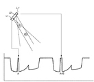
入力が一点であるような場合には、遮光幅(遮光範囲)の中央の角度を用いても座標算出が可能であるが、図15の上部のように、複数の指示具からの入力があり、受光部と複数の指示具の位置関係が、センサユニット1L中の2つの受光部での検出信号(光量分布(遮光範囲))が共に重なってしまうような場合には、このような方法では計算できない。
If the input is a single point, coordinates can be calculated using the central angle of the light shielding width (light shielding range), but there are inputs from a plurality of pointing devices as shown in the upper part of FIG. When the positional relationship between the light receiving unit and the plurality of indicators is such that the detection signals (light quantity distribution (light shielding range)) at the two light receiving units in the
例えば、図15の上部での状態では、センサユニット1L中の図面左側の受光部L1では、指示具Bは指示具Aの影に完全に隠れてしまっており、またもう一方の受光部L2では、指示具Bと指示具Aの遮光範囲が連続してしまっている。
For example, in the state in the upper part of FIG. 15, in the light receiving part L1 on the left side of the drawing in the
そして、図15の下部はその時の出力信号であり、受光部L1での出力信号は指示具Aの遮光範囲(A)のみで構成され、受光部L2での出力信号は、指示具Aと指示具Bの遮光範囲(A+B)がつながった状態として出力される。このような場合には、遮光範囲の中央を用いた計算では正確な入力座標は計算できない。 The lower part of FIG. 15 is the output signal at that time, the output signal at the light receiving unit L1 is composed only of the light shielding range (A) of the indicator A, and the output signal at the light receiver L2 is the indicator A and the indicator It is output as a state where the light shielding range (A + B) of the tool B is connected. In such a case, accurate input coordinates cannot be calculated by calculation using the center of the light shielding range.
そこで、センサユニット1L及び1Rの夫々のセンサユニットで検出された遮光範囲の端部の角度情報を用いて座標算出を行う。
Therefore, the coordinates are calculated using the angle information of the end of the light shielding range detected by each of the
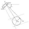
まず、指示具の入力形状を略円形とし、図16のように、センサユニット1L中の1つの受光部L1に対して、指示具Aと指示具Bが一部重なった状態にあるとする。つまり、この受光部L1では、θL1とθL2で規定される遮光範囲が観測されている状態であるとする。
First, it is assumed that the input shape of the pointing tool is substantially circular, and the pointing tool A and the pointing tool B are partially overlapped with one light receiving unit L1 in the
そのとき、各受光部で得られる各々2つの遮光範囲の端部の角度情報の内、水平方向からみた角度として、受光部L2においては最小の角度となるθL2、受光部L1においては最大の角度となるθL1を選択する。 At that time, θL2 which is the minimum angle in the light receiving part L2 and the maximum angle in the light receiving part L1 as the angle seen from the horizontal direction among the angle information of the two light shielding ranges obtained by each light receiving part ΘL1 is selected.
一方、センサユニット1R中の、例えば、受光部R1で観測される角度は、夫々の指示具の遮光範囲で形成される遮光範囲の端部であり、θR11からθR22までの4つの角度が観測される。
On the other hand, for example, the angle observed in the light receiving unit R1 in the
図17はこのような遮光範囲の端部を用いた場合の座標算出を説明するための図である。 FIG. 17 is a diagram for explaining the coordinate calculation when the end portion of such a light shielding range is used.
今、例えば、P点に入力がなされたとした場合、θL1とθR1、θR2の交点を夫々P1(x1,x1)、P2(x2,x2)とすると、入力位置の座標Pは、夫々の交点における角度2θ1、2θ2の2等分線の交点として計算可能となる。 Now, for example, if an input is made at point P, if the intersections of θL1, θR1, and θR2 are P1 (x1, x1) and P2 (x2, x2), respectively, the coordinates P of the input position are at the respective intersections. It can be calculated as the intersection of bisectors of angles 2θ1 and 2θ2.
P1及びP2の座標値は、上述のそれぞれの角度の交点の座標を計算するのと同様の式(2)及び(3)によって計算可能であるので、この座標値と角度情報を用いることにより入力座標P(x,y)を算出することができる。 Since the coordinate values of P1 and P2 can be calculated by the same equations (2) and (3) as those for calculating the intersections of the respective angles described above, the coordinate values and the angle information are used for input. Coordinates P (x, y) can be calculated.
このように、左右のセンサユニット1L及び1Rで検出される遮光範囲の端部情報を用いることで、遮光範囲の中央値を用いることなく、入力に対する入力座標の算出が可能となる。
As described above, by using the edge information of the light shielding range detected by the left and
図18はその算出手順の一例を説明するための図である。 FIG. 18 is a diagram for explaining an example of the calculation procedure.
図のように、P1(x1,y1)とP2(x2,y2)の間の距離をL、夫々の点における角の2等分線の角度をθ1、θ2とすれば、
L= ((x2-x1)2 + (y2-y1)2)0.5 (4)
θ1 = (π-(θL+θR1))/2 (5)
θ2 = (θL+θR2)/2 (6)
ここで、
L1・tanθ1 = L2・tanθ2 (7)
である。よって、
L2=L・tanθ1/(tanθ1 +tanθ2) (但し、tanθ1+tanθ2≠0) (8)
La= L2 / cosθ2 (但し、cosθ2≠0) (9)
これから、Δx、Δyとして
Δx = La・cos(θL-θ2) (10)
Δy = La・sin(θL-θ2) (11)
入力座標として、P(x,y)は、
x = x2 - Δx (12)
y = y2 - Δy (13)
と計算できる。
As shown in the figure, if the distance between P1 (x1, y1) and P2 (x2, y2) is L, and the angle of the bisector of the angle at each point is θ1, θ2,
L = ((x2-x1) 2 + (y2-y1) 2 ) 0.5 (4)
θ1 = (π- (θL + θR1)) / 2 (5)
θ2 = (θL + θR2) / 2 (6)
here,
L1 ・ tanθ1 = L2 ・ tanθ2 (7)
It is. Therefore,
L2 = L · tanθ1 / (tanθ1 + tanθ2) (However, tanθ1 + tanθ2 ≠ 0) (8)
La = L2 / cosθ2 (however, cosθ2 ≠ 0) (9)
From now on, as Δx and Δy, Δx = La · cos (θL-θ2) (10)
Δy = La · sin (θL-θ2) (11)
As input coordinates, P (x, y) is
x = x2-Δx (12)
y = y2-Δy (13)
Can be calculated.
ここで、図16のように、例えば、センサユニット1Lからみて後ろ側の入力点が、完全に影に隠れてしまう、いわゆる、皆既食状態でない状態、つまり、部分食状態である場合には、その入力点は、Pa及びPb、またはPa’及びPb’のどちらかの組み合わせになる。
Here, as shown in FIG. 16, for example, when the input point on the rear side as viewed from the
そこで、θL1、θL2、θR11、θR12、θR21そしてθR22の組み合わせについて、上記のような2等分線の交点に相当する計算を行い、それぞれPa及びPb、またはPa’及びPb’の座標を計算し、どちらの組み合わせが正しい入力座標であるかの判定を行う。 Therefore, for the combinations of θL1, θL2, θR11, θR12, θR21, and θR22, the calculation corresponding to the intersection of the bisectors as described above is performed, and the coordinates of Pa and Pb or Pa ′ and Pb ′ are calculated, respectively. , It is determined which combination is the correct input coordinate.
この組み合わせの判定は、図16における受光部L1及びL2で選択した角度情報とは別の角度情報を用いて行うことができる。 This combination can be determined using angle information different from the angle information selected by the light receiving portions L1 and L2 in FIG.
例えば、図19のように、もう一方の受光部のデータθL21及びθL22と、θR11及びθR12による座標算出結果と、先の受光部での座標算出結果を比較し、Paと重なるのか、あるいはPa’と重るのかを双方の距離等から判定して、PaかPa’のどちらが正しいかの判定を行うことができる。ここで、Paが採用されれば、その組み合わせとして、Pbが自動的に採用されることになる。 For example, as shown in FIG. 19, the data θL21 and θL22 of the other light receiving unit, the coordinate calculation result by θR11 and θR12, and the coordinate calculation result by the previous light receiving unit are compared and overlapped with Pa or Pa ′ It is possible to determine whether Pa or Pa ′ is correct by determining from the distance between the two. Here, if Pa is adopted, Pb is automatically adopted as the combination.
より確実に判定するには、θR21とθR22での座標算出結果を用いて、Pbについて計算を行っても良い。 In order to determine more reliably, Pb may be calculated using the coordinate calculation results at θR21 and θR22.
このように、センサユニット1L(1R)で検出される2つの遮光範囲が部分的に隠れてしまう「部分食」状態であれば、夫々の遮光範囲の端部の角度を検出し、その交点における2等分線に相当する情報を得ることで、複数の入力指示位置を特定することが可能になる。
In this way, in the “partial eclipse” state in which the two light-shielding ranges detected by the
ここで、遮光範囲の端部情報を用いたとしても、いわゆる「皆既食」状態では、その影に隠れた側の指示具の入力の位置を特定することができなくなる。この「皆既食」状態を回避するには、入力指示具の大きさに対して、各センサユニット1L(1R)における複数の受光部間の距離を最適値に決定することによって、どちらかの光学系では領域が部分的に重なった「部分食」状態とすることが可能となる。
Here, even if the edge information of the light-shielding range is used, in the so-called “totally eaten” state, the input position of the pointing tool hidden behind the shadow cannot be specified. In order to avoid this “total eclipse” state, one of the optical systems is determined by determining the distance between the plurality of light receiving portions in each
従って、本願発明では、複数の指示具がどの領域にあっても、センサユニット1L(1R)中に設けられた2組の受光部の内、少なくとも一方の受光部では、必ず「部分食」の状態、あるいは2つの遮光範囲が分離した状態で検出できるように、センサユニット1L(1R)中の受光部の光学的配置を設定している。
Therefore, in the present invention, no matter which region the plurality of indicating tools are, at least one of the two sets of light receiving portions provided in the
また、一方のセンサユニット中の受光部において両方の受光部が「食」状態のとき、遮光範囲の数が両方の受光部において単数となることは既に説明した。このように、一方のセンサユニット中の受光部で検出される遮光範囲の数が両方とも単数となる場合は、指示具が入力面に到達して影が完全に形成されるまでの状態(入力過渡状態)にある場合にも同様に起こりえる。従って、指示具の正しい座標を算出するためには、「食」状態にあるのか、または「入力過渡状態」にあるのかの判定が必要となる。 In addition, as described above, when both light receiving units in the light receiving unit in one sensor unit are in the “eating” state, the number of light shielding ranges is singular in both light receiving units. Thus, when the number of light-shielding ranges detected by the light receiving unit in one sensor unit is both singular, the state until the indicator reaches the input surface and the shadow is completely formed (input It can happen in the same way when it is in a transient state. Therefore, in order to calculate the correct coordinates of the pointing tool, it is necessary to determine whether it is in the “eating” state or the “input transient state”.
実際の計算については、以下のようになる。 The actual calculation is as follows.
まず、上述説明したように、各々受光部からの光量分布データの取得を行う。 First, as described above, light amount distribution data is acquired from each light receiving unit.
得られた各光量分布データから、遮光範囲の数を閾値等を用いて算出する。遮光範囲の数により、入力がない場合と、一箇所に対して入力(単一点入力)が行われた場合と、少なくとも2箇所に対して入力(複数点入力)が行われた場合の判定が可能になるとともに、演算に用いるデータを選択することができる。 From the obtained light quantity distribution data, the number of light shielding ranges is calculated using a threshold or the like. Depending on the number of light-shielding ranges, the determination is made when there is no input, when input is performed at one place (single point input), and when input is performed at least two places (multiple point input). It becomes possible, and the data used for the calculation can be selected.
図20は、センサユニット1L内の2つの受光部をL1及びL2、センサユニット1R内の2つの受光部をR1及びR2とする場合に、各受光部で検出される遮光範囲の数の組み合わせを示している。遮光範囲の数の組み合わせは、最大入力数を2としたとき、入力がない場合を含めて17通りとなる。
FIG. 20 shows combinations of the number of light-shielding ranges detected by each light receiving unit when the two light receiving units in the
受光部L1,L2、R1,R2のすべてにおいて、入力が「1」の場合には、単一点入力の場合と、2つの入力が接触している場合とが考えられるが、実施形態1では、接触も単一点入力として扱うこととする。但し、指示具の入力幅等の指示具の形状情報が既知である場合には、その形状情報に基づいて、2つの入力が接触している場合を検出するようにしてもよい。 In all of the light receiving portions L1, L2, R1, and R2, when the input is “1”, there are a case where the input is a single point and a case where the two inputs are in contact with each other. Touch is also treated as a single point input. However, when the shape information of the pointing tool such as the input width of the pointing tool is known, a case where two inputs are in contact may be detected based on the shape information.
このように、遮光範囲の数を計数することで、「入力無し」、「単一点入力」、「複数点入力」の入力状態を判定することができる。各センサユニットで検出される遮光範囲が、一つしかない単一点入力の場合には、遮光範囲の端部情報を用いた座標算出方法で座標算出を行ってもよいし、あるいは、従来とおりの遮光範囲の中央を計算して、座標算出を行ってもかまわない。 Thus, by counting the number of light shielding ranges, it is possible to determine the input states of “no input”, “single point input”, and “multiple point input”. When the single light shielding range detected by each sensor unit is a single point input, the coordinate calculation may be performed by the coordinate calculation method using the edge information of the light shielding range, or as usual. Coordinates may be calculated by calculating the center of the light shielding range.
複数点入力の場合、入力が各々独立に検出できている遮光範囲が2つのものと、センサユニットに対して入力位置の関係が「食」状態にあるような、1つの場合とが混在することになる。 In the case of multi-point input, there are a mixture of two light-shielding ranges where each input can be detected independently and one case where the input position is in the “eating” state relative to the sensor unit. become.
このような場合に、どの遮光範囲の組み合わせで座標算出を行うかについては、夫々の遮光範囲の数から決定する。 In such a case, the combination of the light shielding ranges for which the coordinate calculation is performed is determined from the number of the respective light shielding ranges.
まず、各遮光範囲の数の内、2箇所の遮光範囲を検出している受光部を選択し、選択した受光部からの検出信号を座標算出第1データとする。このとき、複数の受光部で遮光範囲を2箇所検出している場合には、優先順位を予め決定しておき、その優先順位に従って受光部を選択すればよい。 First, among the number of light shielding ranges, a light receiving unit that detects two light shielding ranges is selected, and a detection signal from the selected light receiving unit is used as first data for coordinate calculation. At this time, when two light-shielding ranges are detected by a plurality of light receiving units, the priority order may be determined in advance and the light receiving unit may be selected according to the priority order.
次に、座標算出第1データとして選択された受光部のセンサユニットと反対側のセンサユニット内の受光部の検出信号に着目し、そのとき、各受光部で得られる複数の遮光範囲の端部の角度情報の内、水平方向からみた角度に対して、受光部L2(またはR2)においては最小の角度となる角度情報、受光部L1(またはR1)においては最大の角度となる角度情報を選択し、これを座標算出第2データとする。即ち、センサユニットで検出される複数の端部情報の内、両端の角度情報を座標算出第2データとして選択する。 Next, paying attention to the detection signal of the light receiving part in the sensor unit opposite to the sensor unit of the light receiving part selected as the coordinate calculation first data, at that time, end portions of a plurality of light shielding ranges obtained in each light receiving part Among the angle information, the angle information indicating the minimum angle in the light receiving unit L2 (or R2) and the angle information indicating the maximum angle in the light receiving unit L1 (or R1) with respect to the angle viewed from the horizontal direction are selected. This is the coordinate calculation second data. That is, angle information at both ends is selected as coordinate calculation second data from among a plurality of pieces of end information detected by the sensor unit.
次に、座標算出第2データとして選択された受光部のセンサユニットと同じセンサユニットにおける各受光部で得られる複数の遮光範囲の端部の角度情報の内、水平方向からみた角度に対して、例えば、受光部L2(またはR2)においては最大の角度となる角度情報、受光部L1(またはR1)においては最小の角度となる角度情報を選択し、これを虚実判定データとする。 Next, with respect to the angle seen from the horizontal direction among the angle information of the ends of the plurality of light shielding ranges obtained by each light receiving unit in the same sensor unit as the sensor unit of the light receiving unit selected as the coordinate calculation second data, For example, angle information indicating the maximum angle is selected in the light receiving unit L2 (or R2), and angle information indicating the minimum angle is selected in the light receiving unit L1 (or R1), and this is used as the truth determination data.
これは、先に述べたように、複数の入力がある場合に、真に入力した座標(実座標)のほかに、検出信号の組み合わせによって生じる虚の座標が算出されるので、真の座標がどれであるかを判定するのに用いられるものである。 As described above, when there are a plurality of inputs, in addition to the true input coordinates (real coordinates), the imaginary coordinates generated by the combination of detection signals are calculated. It is used to determine which.
また、上述した座標算出第1データ、座標算出第2データ、虚実判定データは、先述したように検出した状態が「食」状態にあるか、または入力過渡状態にあるかの判定にも用いる。 Further, the coordinate calculation first data, the coordinate calculation second data, and the truth determination data described above are also used for determining whether the detected state is the “eating” state or the input transient state as described above.
この入力過渡状態の判定(検出状態の正当性の判定)について、図21を用いて説明する。 The determination of the input transient state (determination of the validity of the detection state) will be described with reference to FIG.
図中Aで示した接線が座標算出第1データ、Bが座標算出第2データ、Cが虚実判定データである。そして、これらのデータを用いて、入力過渡状態の判定を行う。 In the figure, the tangent indicated by A is the first coordinate calculation data, B is the second coordinate calculation data, and C is the truth determination data. Then, the input transient state is determined using these data.
まず、遮光範囲の端部の角度情報A11、A12、B11で計算した座標値をP11、同様に、A11、A12、B22で計算した座標値をP21としたとき、最も単純な手法として、この2つの座標値P11とP21を比較することで、入力過渡状態を判定できる。即ち、両者の位置座標を比較して両者の距離が所定距離未満にあれば、入力過渡状態であり、所定距離以上離れていれば通常の入力とすることができる。 First, the coordinate value calculated by the angle information A11, A12, B11 of the end portion of the light shielding range is P11, and similarly, the coordinate value calculated by A11, A12, B22 is P21. The input transient state can be determined by comparing the two coordinate values P11 and P21. That is, when the positional coordinates of the two are compared and the distance between the two is less than the predetermined distance, the input is in a transient state, and when the distance is more than the predetermined distance, normal input can be performed.
次に、より詳細な入力過渡状態判定手法について説明する。 Next, a more detailed input transient state determination method will be described.
先に選択した座標算出第1データのうちのA12に関して、座標算出第2データB11及びB22と虚実判定データC21及びC12との交点として、交点座標値CP11、CP12、CP13、CP14を算出する。 With respect to A12 in the first coordinate calculation data selected earlier, intersection coordinate values CP11, CP12, CP13, and CP14 are calculated as intersections between the coordinate calculation second data B11 and B22 and the truth determination data C21 and C12.
即ち、座標算出第1データとして選択した受光部のデータの内、反対側のセンサユニットに近い側から2番目の角度情報に関して、座標算出第2データ及び虚実判定データとして選択したセンサユニットで得られる全ての角度情報について各々の交点を算出する。 That is, among the data of the light receiving unit selected as the coordinate calculation first data, the second angle information from the side close to the opposite sensor unit is obtained by the sensor unit selected as the coordinate calculation second data and the truth determination data. Each intersection is calculated for all angle information.
得られた交点座標に関して、CP11とCP12の距離、そしてCP13とCP14の距離をそれぞれ算出する。そして、各々の距離を比較することによって、入力過渡状態であるか否かを判定する。 Regarding the obtained intersection coordinates, the distance between CP11 and CP12 and the distance between CP13 and CP14 are calculated. And it is determined whether it is an input transient state by comparing each distance.
ここで、交点CP12とCP11の距離差をΔL1、交点CP14とCP13の距離差をΔL2とすると、入力過渡状態の場合には、
ΔL1≒ΔL2<K1
の関係が成り立つ。即ち、ΔL1及びΔL2の両方が所定値より小さい場合に、入力過渡状態と判定することができる。
Here, when the distance difference between the intersection points CP12 and CP11 is ΔL1, and the distance difference between the intersection points CP14 and CP13 is ΔL2, in the case of an input transient state,
ΔL1 ≒ ΔL2 <K1
The relationship holds. That is, when both ΔL1 and ΔL2 are smaller than a predetermined value, it can be determined that the input transient state.
一方、座標算出第1データのうち、座標算出第1データとして選択したセンサユニットと反対側のセンサユニットに対して一番遠い角度情報であるA22に対して、上記と同様に交点を算出してもよい。この場合、比較する距離の各々が所定値以上である場合に入力過渡状態と判定することができる。 On the other hand, in the coordinate calculation first data, an intersection point is calculated in the same manner as described above for A22 which is the farthest angle information with respect to the sensor unit opposite to the sensor unit selected as the coordinate calculation first data. Also good. In this case, an input transient state can be determined when each of the distances to be compared is greater than or equal to a predetermined value.
また、交点CP22とCP21の距離差をΔL3、交点CP24とCP23の距離差をΔL4とすると、入力過渡状態の場合には、
ΔL4≒ΔL3>K2
の関係が成り立つ。即ち、ΔL3及びΔL4の両方が所定値より大きい場合に、入力過渡状態と判定することができる。
If the distance difference between the intersection points CP22 and CP21 is ΔL3 and the distance difference between the intersection points CP24 and CP23 is ΔL4,
ΔL4≈ΔL3> K2
The relationship holds. That is, when both ΔL3 and ΔL4 are larger than a predetermined value, it can be determined that the input transient state.
尚、上記K1、K2は、入力過渡状態であるか否かを判定するにあたり、あらかじめ決められた指示具の径と座標入力有効領域から算出される、適宜設定することのできる所定の定数である。そして、これらの定数は、工場出荷時にメモリに記憶され、随時読み出すことによって判定時に用いることができる。 The above-described K1 and K2 are predetermined constants that can be appropriately set and are calculated from a predetermined diameter of the pointing tool and the coordinate input effective area when determining whether or not the input transient state is present. . These constants are stored in a memory at the time of factory shipment, and can be used at the time of determination by reading them as needed.
一方、この定数K1やK2を用いない手法として、各交点間距離差ΔL1、ΔL2、ΔL3、ΔL4をそれぞれ比較して判定する手法がある。各交点間距離差ΔL1、ΔL2、ΔL3、ΔL4は、入力過渡状態の場合には、
ΔL3>ΔL1 かつ ΔL4>ΔL2
の関係が成り立つ。即ち、座標算出第2データのセンサユニットに近い側の入力の端部情報の各々に対応する座標算出第1データとの交点間の距離差同士を比較したときに、上記の関係が成り立つ場合には、入力過渡状態と判定することができる。
On the other hand, as a method that does not use the constants K1 and K2, there is a method of comparing and determining the distance differences ΔL1, ΔL2, ΔL3, and ΔL4 between the intersections. In the case of an input transient state, the distance differences ΔL1, ΔL2, ΔL3, ΔL4 between the intersections are as follows:
ΔL3> ΔL1 and ΔL4> ΔL2
The relationship holds. That is, when the above relationship is established when the distance difference between the intersection points with the coordinate calculation first data corresponding to each of the input end information close to the sensor unit of the coordinate calculation second data is compared. Can be determined as an input transient state.
尚、上述した複数種類の入力過渡状態の判定手法は、判定精度や計算量に鑑みて装置によって適宜選択すればよい。 Note that the above-described method for determining the plurality of types of input transient states may be appropriately selected depending on the apparatus in view of determination accuracy and calculation amount.
また、上述した入力過渡状態の判定は、「皆既食」状態判定として用いることもできる。例えば、これまで説明した座標入力装置においては、既定の座標入力用指示具を用いた場合であり、少なくとも一方の遮光端部が各受光部で検出できるように、指示具が遮光する部分の径に対してセンサユニットにおける受光部の設置距離が適切な値に設定されている。 Further, the determination of the input transient state described above can also be used as the “total eating” state determination. For example, in the coordinate input device described so far, it is a case where a predetermined coordinate input indicator is used, and the diameter of the portion shielded by the indicator so that at least one light-shielding end can be detected by each light receiver. On the other hand, the installation distance of the light receiving part in the sensor unit is set to an appropriate value.
しかしながら、入力が上記のような既定の指示具で行われない場合には、センサユニットに近い指示具によって、後ろ側の入力が隠れてしまいセンサユニット中の受光部の両方で検出できない現象、即ち、皆既食が生じる場合がある。この皆既食状態判定を行う場合にも、先述した入力過渡状態判定と同様の手法を用いることによって、皆既食か否かの判定を行うことができる。そして、皆既食状態と判定された場合には、操作者にその旨を報知するなどの措置をして適正な入力指示具で入力するよう促すことが可能となる。 However, in the case where the input is not performed with the above-described predetermined indicator, the phenomenon that the input on the rear side is hidden by the indicator close to the sensor unit and cannot be detected by both the light receiving units in the sensor unit, that is, A total eclipse may occur. Even when this total eating state determination is performed, it is possible to determine whether or not it is a total eating state by using the same method as the input transient state determination described above. When it is determined that the total eating state is present, it is possible to prompt the operator to input with an appropriate input instruction tool by taking measures such as notifying the operator of that fact.
上述した入力過渡状態判定によって、入力過渡状態ではなく適切な座標算出可能な状態であると判定された場合には、以下の処理が行われる。 When it is determined by the above-described input transient state determination that the coordinate is not an input transient state and an appropriate coordinate can be calculated, the following processing is performed.
図20で示したように、座標算出第1データとして選択される受光部で検出する遮光範囲の数は必ず複数となるが、座標算出第2データとして選択される受光部で検出する遮光範囲の数は複数の場合と単数の場合がある。つまり、座標算出第2データとして選択したセンサユニットにおける受光部では、両方が単数の場合、片方が単数(片方が複数)の場合、両方が複数の場合の3タイプに分類することができる。 As shown in FIG. 20, the number of light-shielding ranges detected by the light-receiving unit selected as the coordinate calculation first data is always plural, but the light-shielding ranges detected by the light-receiving unit selected as the coordinate calculation second data The number may be plural or singular. That is, in the light receiving part in the sensor unit selected as the coordinate calculation second data, when both are singular, when one is singular (one is plural), it can be classified into three types.
ここで、この3タイプに対応する入力状態の一例を、図22A〜図22Cに示す。 Here, an example of the input state corresponding to these three types is shown in FIGS. 22A to 22C.
各々の図中Aで示した接線が座標算出第1データ、Bが座標算出第2データ、Cが虚実判定データ、Dが虚実判定予備データ(図22B及び図22C)である。 The tangent indicated by A in each figure is the first coordinate calculation data, B is the second coordinate calculation data, C is the true / false determination data, and D is the false determination preliminary data (FIGS. 22B and 22C).
座標算出は、まず、座標算出第1データの一方の遮光範囲、例えば、図22Aでは、A11及びA12に対して、座標算出第2データB11及びB12、及び虚実判定データC11及びC12の組み合わせで、先に説明したような遮光範囲の端部情報を用いて座標算出を行う。 The coordinate calculation is performed by first combining one of the light shielding ranges of the coordinate calculation first data, for example, in FIG. 22A, with the coordinate calculation second data B11 and B12 and the truth determination data C11 and C12 with respect to A11 and A12. Coordinate calculation is performed using the edge information of the light shielding range as described above.
このとき、座標算出第2データB11及びB12で算出した座標値をP11及びP12、虚実判定データC11及びC12で算出した座標値を虚実判定座標値としてP21及びP22とする。この時点で、算出された4つの座標値の内、少なくとも2つの座標値は略等しい値となり、指示具の位置座標を示す値となる。 At this time, the coordinate values calculated by the coordinate calculation second data B11 and B12 are P11 and P12, and the coordinate values calculated by the truth determination data C11 and C12 are P21 and P22 as the truth determination coordinate values. At this time, at least two of the four calculated coordinate values are substantially equal to each other, and are values indicating the position coordinates of the pointing tool.
ここで、座標算出第2データとして選択したセンサユニットの受光部では、検出した遮光範囲の数が複数の場合と単数の場合があり、両方の受光部において遮光範囲の数が単数である場合には、どちらかの受光部において「皆既食」状態が含まれている可能性がある。この場合、選択する角度情報によっては、センサユニットに近い側の座標算出には使えるが、遠い側の算出には使えない。 Here, in the light receiving part of the sensor unit selected as the coordinate calculation second data, the number of detected light shielding ranges may be plural or singular, and the number of light shielding ranges in both light receiving parts is singular. There is a possibility that the “total eclipse” state is included in either of the light receiving units. In this case, depending on the angle information to be selected, it can be used for calculating coordinates on the side closer to the sensor unit, but cannot be used for calculating on the far side.
しかしながら、上述したように、座標算出第2データとして、選択したセンサユニットの複数の遮光範囲端部情報のうち、両端のデータに相当する角度情報をそれぞれの受光部から選択することによって、部分食、皆既食にかかわらず、正しく座標候補を算出することができる。 However, as described above, as the coordinate calculation second data, by selecting angle information corresponding to the data at both ends from the plurality of light shielding range end information of the selected sensor unit, the partial eclipse is selected. The coordinate candidates can be calculated correctly regardless of the total eclipse.
次に、座標の虚実判定を行う。この処理は、すべての組み合わせの座標を算出してから行ってもかまわないが、先に一方の座標値に対して、虚実判定を行っておくことで、不要な座標算出を行わずに処理時間の短縮が図れる。 Next, the true / false judgment of coordinates is performed. This process may be performed after calculating the coordinates of all the combinations, but it is possible to perform the processing time without calculating unnecessary coordinates by performing the true / false determination on one coordinate value first. Can be shortened.
先のP11、P12、P21、P22に対して、どの座標値が正しい値かを夫々の距離の近さで判定する。 Which coordinate value is correct with respect to the previous P11, P12, P21, and P22 is determined based on the proximity of each distance.
それぞれ、P11とP21及びP22、P12とP21及びP22の距離を算出して、一番近い組み合わせからP11またはP12のどちらかを真の座標値として選択する。 The distances between P11 and P21 and P22 and P12 and P21 and P22 are calculated, and either P11 or P12 is selected as the true coordinate value from the closest combination.
虚実判定結果によって、真の座標値がP11に選択されれば、残りの未計算の座標値は、P14となるので、その座標値を算出する。一方、虚実判定結果によって、真の座標値にP12が選択されれば、P13の座標算出を行う。 If the true coordinate value is selected as P11 based on the true / false determination result, the remaining uncalculated coordinate value is P14, and the coordinate value is calculated. On the other hand, if P12 is selected as the true coordinate value based on the true / false determination result, the coordinate calculation of P13 is performed.
このようにして、実際の入力に対する座標の判定(虚実判定)を行うことができる。 In this way, it is possible to perform coordinate determination (true / false determination) with respect to actual input.
図22B、図22Cのような場合にも、同様に処理することで座標算出が可能になる。座標算出に際して、1つのセンサユニットの2つの受光部が検出する遮光範囲の数がそれぞれ複数の場合には、その遮光範囲の端部情報の両端から座標算出しても良いが、片側の端部情報からのみで計算してもかまわない。あるいは、従来通り遮光範囲の中央を計算して、座標算出に用いてもかまわない。 Even in the case of FIG. 22B and FIG. 22C, the coordinates can be calculated by performing the same processing. When calculating the coordinates, if there are a plurality of light-shielding ranges detected by the two light-receiving units of one sensor unit, the coordinates may be calculated from both ends of the edge information of the light-shielding range. You may calculate only from information. Alternatively, the center of the light shielding range may be calculated as before and used for coordinate calculation.
尚、必要であれば、虚実判定予備データDの角度情報を用いて虚実判定を実行してもかまわない。 If necessary, the true / false determination may be executed using the angle information of the false determination preliminary data D.
ここで、センサユニット内の各受光部が検出する遮光範囲の数によるデータの割り振りについて述べると、座標算出第1データ、座標算出第2データ、虚実判定データに夫々センサユニットのどの受光部、角度情報を割り振るかは、単一点入力の時には、L1、R1あるいはL2、R2のどの組み合わせを用いて計算してもかまわない。 Here, the allocation of data according to the number of light shielding ranges detected by each light receiving unit in the sensor unit will be described. Which light receiving unit and angle of the sensor unit are included in the first coordinate calculation data, the second coordinate calculation data, and the truth determination data, respectively. Whether to allocate information may be calculated using any combination of L1, R1 or L2, R2 at the time of single point input.
また、各センサユニットの2つの受光部の両検出信号がともに複数の遮光範囲を検出している場合には、どちらの検出信号を座標算出第1データにしてもかまわない。 When both detection signals of the two light receiving portions of each sensor unit detect a plurality of light shielding ranges, either detection signal may be used as the first coordinate calculation data.
また、上述の例では、虚実判定データは、座標算出第1データで選択したセンサユニットと反対のセンサユニットから、座標算出第2データとして選択した角度情報とは別の角度情報を用いていたが、座標算出第1データで選択したセンサユニットの受光部とは別の受光部で検出された角度情報を用いてもよい。 In the above example, the truth determination data uses angle information different from the angle information selected as the coordinate calculation second data from the sensor unit opposite to the sensor unit selected by the coordinate calculation first data. The angle information detected by a light receiving unit different from the light receiving unit of the sensor unit selected by the coordinate calculation first data may be used.
この場合、図22Dに示すように、A11、A12、B11、B12を用いて、P11、P12を計算し、B11、B12、C11、C12を用いて、P21、P22を計算する。 In this case, as shown in FIG. 22D, P11 and P12 are calculated using A11, A12, B11, and B12, and P21 and P22 are calculated using B11, B12, C11, and C12.
このP11、P12、P21、P22に対して、どの座標値が正しい値かを夫々の距離の近さで判定する。 With respect to P11, P12, P21, and P22, which coordinate value is correct is determined based on the proximity of each distance.
このようにして、座標算出第1データと同一のセンサユニットの受光部のデータを用いても、実際の入力に対する座標の判定(虚実判定)を行うことができる。 In this way, even when the data of the light receiving unit of the sensor unit that is the same as the first coordinate calculation data is used, it is possible to determine the coordinates (true / false determination) with respect to the actual input.
<座標値の連続性の判定>
上述したように、複数の受光部を有するセンサユニットを用い、遮光範囲の端部情報を用いて、座標算出及び座標の虚実判定を行うことで、複数の入力の座標値を決定することができる。
<Determination of continuity of coordinate values>
As described above, coordinate values of a plurality of inputs can be determined by using a sensor unit having a plurality of light receiving units and calculating coordinates and determining the truth of the coordinates using the edge information of the light shielding range. .
そして、得られた複数の座標値については、このまま座標値を出力しただけでは、受信側の外部端末で、2つの座標値の区別がつかず両者をつないでしまうようなことになりかねない。 As for the obtained coordinate values, if the coordinate values are output as they are, the external terminal on the receiving side cannot distinguish the two coordinate values and may connect the two.
そこで、2つの座標値を区別するために、座標の連続性を表す識別子を座標値の出力の際には付加する。 Therefore, in order to distinguish the two coordinate values, an identifier representing the continuity of the coordinates is added when outputting the coordinate values.
複数の座標値の、その連続性は、各サンプリング毎に前回の座標値との差分を計算して、夫々をその近いものを当てはめることで可能である。 The continuity of a plurality of coordinate values can be achieved by calculating the difference from the previous coordinate value for each sampling and applying each to the closest one.
遮光範囲が最初に検出された時には、例えば、検出された順にID番号(フラグ)を付加する。 When the light shielding range is first detected, for example, ID numbers (flags) are added in the order of detection.
図23のように、2つの座標値P1(X1n,Y1n)、P2(X2n,Y2n)が得られたときに、前回サンプリング時の座標値がID0:X1n−1,Y1n−1、ID1:X2n−1,Y2n−1であれば、P1,P2ともども、夫々に対する差分を計算して、近い方を採用し、P1をID0、P2をID1とする。このように、座標値の連続性の判定を行い、夫々の座標値に対して、このIDを割り振って座標値を出力する。 As shown in FIG. 23, when two coordinate values P1 (X1n, Y1n) and P2 (X2n, Y2n) are obtained, the coordinate values at the time of previous sampling are ID0: X1n-1, Y1n-1, ID1: X2n. If it is −1, Y2n−1, the difference between P1 and P2 is calculated, the closest one is adopted, P1 is ID0, and P2 is ID1. Thus, the continuity of the coordinate values is determined, and this ID is assigned to each coordinate value and the coordinate value is output.
そして、外部端末側で、このIDを参照することで、座標値の連続性を判定し、線で連結する等の描画の処理を行うようにすればよい。 Then, by referring to this ID on the external terminal side, the continuity of the coordinate values may be determined, and drawing processing such as connecting with a line may be performed.
<ペン信号の検出>
指示具として、例えば、先端にスイッチ等の信号発生部を設けたペンを用いることで、文字の入力等における「尾引き」の問題が発生しない、スムーズな入力が可能になる。
<Pen signal detection>
By using, for example, a pen provided with a signal generation unit such as a switch at the tip as the pointing tool, smooth input without causing a “tailing” problem in character input or the like becomes possible.
ここで、「尾引き」とは、例えば、『あ』と言う文字を入力したにもかかわらず、座標入力面をタッチする直前/直後において、余分な軌跡が表示され、操作者が意図した軌跡とは異なる表示が得られる現象である。 Here, for example, “trailing” means that an extra trajectory is displayed immediately before / after touching the coordinate input surface even though the character “a” is entered, and the trajectory intended by the operator is displayed. This is a phenomenon in which a different display is obtained.
座標入力装置から外部端末に出力する情報は、上述のように、座標値だけでなく、指示具から得られるスイッチ情報(例えば、マウスの左ボタンの情報に相当するようなアップダウン情報S0や、マウスの右ボタンに相当するペンサイドスイッチ情報S1)や、上記のような座標の連続性を表す識別子ID等がある。それ以外にも、指示具固有のペンID情報等がある。 As described above, the information output from the coordinate input device to the external terminal includes not only the coordinate value but also switch information obtained from the pointing tool (for example, up / down information S0 corresponding to the information of the left button of the mouse, There are pen side switch information S1) corresponding to the right button of the mouse, an identifier ID representing the continuity of coordinates as described above, and the like. In addition, there is pen ID information unique to the pointing tool.
スイッチ情報の出力方法としては、音波や電波を用いたり、光を用いることでも可能である。 As a method for outputting switch information, sound waves, radio waves, or light can be used.
図1のペン信号受信部5は、指示具からの信号を受信し、その信号がどの座標値の信号であるかを判定して、座標値を送信する際のペンアップダウン信号やマウスのボタン信号として用いられる。 The pen signal receiving unit 5 in FIG. 1 receives a signal from the pointing tool, determines which coordinate value the signal is, and a pen up / down signal or mouse button when transmitting the coordinate value. Used as a signal.
指示具からの情報の座標値への割り付けは、例えば、光を用いた場合、座標入力有効領域3に対して、ペン信号受信部を複数設け、夫々で異なる領域からの信号を得るようにする。
For example, in the case of using light, a plurality of pen signal receiving units are provided for the coordinate input
このように構成して、複数の指示具による座標値が得られる場合に、異なる領域のどこにその座標値があたるかを判定し、その領域で得られた信号の情報(スイッチ信号や、指示具のペンID情報)をその座標値と関連付けるようにする。そして、これらのスイッチ情報や指示具固有のペンID情報や、座標値の連続性を表すID情報等を付帯情報として、座標値に付加して外部端末に出力する。 With this configuration, when coordinate values by a plurality of indicators are obtained, it is determined where the coordinate values are in different areas, and information on signals obtained in the areas (switch signals and indicators) The pen ID information) is associated with the coordinate value. Then, the switch information, the pen ID information unique to the pointing tool, the ID information indicating the continuity of the coordinate values, and the like are added to the coordinate values as incidental information and output to the external terminal.
ここで、図24は、そのような付帯情報と座標値とを出力する際のフォーマット例である。 Here, FIG. 24 shows a format example when outputting such incidental information and coordinate values.
図24では、byte0に付帯情報として、スイッチ情報及びペンID情報が付加され、それ以降、byte1からbyte4に、指示具の指示位置である座標(x,y)の座標値がそれぞれ格納されて、外部端末に出力される。外部端末側では、受信するこのデータを解析することで、軌跡の描画やメニュー操作の実行を制御する。
In FIG. 24, switch information and pen ID information are added as supplementary information to
<座標算出処理フローの説明>
図25は本発明の実施形態1の座標入力装置が実行する座標算出処理を示すフローチャートである。
<Description of coordinate calculation processing flow>
FIG. 25 is a flowchart showing coordinate calculation processing executed by the coordinate input device according to the first embodiment of the present invention.
図25では、センサユニットでのデータ取得から座標算出までの手順を示している。 FIG. 25 shows a procedure from data acquisition to coordinate calculation in the sensor unit.
電源が投入されると、ステップS101で、制御・演算ユニット2のポート設定、タイマ設定等の座標入力装置に係る各種初期化を行う。その後に、不揮発メモリ等から基準データや補正用の定数等の初期データをそれぞれ読み出し、演算・制御ユニット2のメモリ132に格納する。
When the power is turned on, in step S101, various initializations related to the coordinate input device such as port setting and timer setting of the control /
また、各センサユニット毎に、図6のような、照明無しの時の光量分布データ81と、初期入力が無いときの光量分布データ82を、初期データとして取り込み、メモリ132に記憶する。
Further, for each sensor unit, as shown in FIG. 6, light
ここまでの処理が、電源投入時の初期設定動作になる。この初期設定動作は、座標入力装置に構成されているリセットスイッチ等により操作者の意図によって動作するように構成しても良いことはいうまでも無く、この初期設定動作を経て、通常の指示具による座標入力動作状態に移行することになる。 The processing so far is the initial setting operation when the power is turned on. It goes without saying that this initial setting operation may be configured to operate according to the operator's intention using a reset switch or the like configured in the coordinate input device. Will shift to the coordinate input operation state.
ステップS102で、座標入力が連続して行われているか否かを示すフラグを初期化(クリア)する。ステップS103で、各センサユニットの投光部を点灯させ、光量分布データを受光部より取得する。 In step S102, a flag indicating whether coordinate input is continuously performed is initialized (cleared). In step S103, the light projecting unit of each sensor unit is turned on, and the light amount distribution data is acquired from the light receiving unit.
ステップS104で、センサユニット1Lおよび1Rの各2つの受光部のうち各々一方の受光部(第1受光部)で取得した光量分布データは、先の初期データに対して差分及び比を計算し、例えば、閾値を越えるものがあるか否かの判定などによって、遮光範囲の検出を実行する。
In step S104, the light quantity distribution data acquired by one of the two light receiving parts of each of the
ステップS105で、ステップS104で検出した遮光範囲の角度情報から、他方の受光部(第2受光部)に対応するデータの遮光範囲探索開始位置(画素番号)を算出し、ステップS104と同様にもう一方の受光部のデータの遮光範囲の検出を実行する。 In step S105, the light shielding range search start position (pixel number) of the data corresponding to the other light receiving portion (second light receiving portion) is calculated from the angle information of the light shielding range detected in step S104. The detection of the light shielding range of the data of one light receiving unit is executed.
ステップS106で、遮光範囲の検出結果に基づいて、指示具による入力の有無を判定する。入力がない場合(ステップS106でNO)、ステップS102に戻る。一方、入力がある場合(ステップS106でYES)、ステップS107に進む。 In step S106, the presence / absence of input by the pointing tool is determined based on the detection result of the light shielding range. If there is no input (NO in step S106), the process returns to step S102. On the other hand, if there is an input (YES in step S106), the process proceeds to step S107.
ステップS107で、遮光範囲の検出結果に基づいて、センサユニットの各受光部毎の遮光範囲の数を検出する。ステップS108で、遮光範囲の数の検出結果に基づいて、指示具による入力が複数点入力であるか否かを判定する。複数点入力でない場合(ステップS108でNO)、つまり、単一点入力である場合、ステップS109に進み、単一点入力における座標算出を実行する。このときの座標算出は、遮光範囲の端部情報を用いた計算でも良いし、遮光範囲の中央を用いたものでもかまわない。 In step S107, based on the detection result of the light shielding range, the number of light shielding ranges for each light receiving unit of the sensor unit is detected. In step S108, it is determined based on the detection result of the number of light shielding ranges whether or not the input by the pointing tool is a multipoint input. If it is not a multi-point input (NO in step S108), that is, if it is a single-point input, the process proceeds to step S109, and coordinate calculation in the single-point input is executed. The coordinate calculation at this time may be calculation using edge information of the light shielding range, or may be performed using the center of the light shielding range.
一方、複数点入力である場合(ステップS108でYES)、ステップS110に進み、その遮光範囲の数に従って、座標算出第1データ、座標算出第2データ、及び虚実判定データをそれぞれ決定する。そして、これらのデータをメモリ132に記憶する。
On the other hand, if the input is a plurality of points (YES in step S108), the process proceeds to step S110, and the coordinate calculation first data, the coordinate calculation second data, and the truth determination data are determined according to the number of light shielding ranges. These data are stored in the
ステップS111で、ステップS110で決定した各データに基づいて、入力過渡状態の判定を行う。入力過渡状態である場合(ステップS111でYES)、その回のデータを無効として、ステップS103に戻る。一方、入力過渡状態でない場合(ステップS111でNO)、即ち、適正な入力状態(正当な入力状態)である場合、ステップS112に進む。 In step S111, the input transient state is determined based on each data determined in step S110. If it is in an input transient state (YES in step S111), the data at that time is invalidated and the process returns to step S103. On the other hand, if it is not an input transient state (NO in step S111), that is, if it is an appropriate input state (legal input state), the process proceeds to step S112.
ステップS112で、夫々の遮光範囲の端部データを算出し、その端部データから座標値及び判定座標値を算出する。 In step S112, end data of each light shielding range is calculated, and coordinate values and determination coordinate values are calculated from the end data.
遮光範囲(入力点)が複数の場合、ここで算出される座標値は、実際に入力された、実の点と虚の点が算出されることになる。そこで、ステップS113で、座標値と判定座標値から座標値の虚実判定を実行する。 When there are a plurality of light shielding ranges (input points), the actual and imaginary points actually input are calculated as the coordinate values calculated here. Therefore, in step S113, the true / false determination of the coordinate value is executed from the coordinate value and the determination coordinate value.
虚実判定によって、実座標が判定されたら、ステップS114で、それに対応する側の残りの座標値を算出する。座標値が確定したら、ステップS115で、連続入力の有無を判定する。尚、この判定は、連続入力の有無を示すフラグに基づいて実行する。 If the real coordinates are determined by the true / false determination, the remaining coordinate values on the corresponding side are calculated in step S114. When the coordinate value is determined, the presence / absence of continuous input is determined in step S115. This determination is performed based on a flag indicating the presence / absence of continuous input.
連続入力がない場合(ステップS115でNO)、ステップS117に進む。一方、連続入力がある場合(ステップS115でYES)、ステップS116に進む。 If there is no continuous input (NO in step S115), the process proceeds to step S117. On the other hand, if there is continuous input (YES in step S115), the process proceeds to step S116.
ステップS116で、それ以前に記憶されている座標値(前回の座標値等)との差分などから、連続性判定を実行する。 In step S116, continuity determination is executed based on a difference from a previously stored coordinate value (such as the previous coordinate value).
連続性判定がなされたら、ステップS117で、連続入力フラグをセットし、また、今の座標値を次の連続性判定のためにメモリ132に記憶する。
If the continuity determination is made, a continuous input flag is set in step S117, and the current coordinate value is stored in the
次に、ステップS118で、ID等の付帯情報を座標値に付加する。特に、連続していると判定された座標値には、前回と同じIDを付加し、新規に検出された座標値に対しては、未使用のIDを付加することになる。また、スイッチ情報などがある場合には、その情報も付加する。 Next, in step S118, additional information such as an ID is added to the coordinate value. In particular, the same ID as the previous time is added to the coordinate values determined to be continuous, and the unused ID is added to the newly detected coordinate value. If there is switch information or the like, that information is also added.
このように、付帯情報を有する座標値を、ステップS119で、外部端末に出力する。その後、データ取得のループを、電源OFFまで繰り返すことになる。 In this way, the coordinate value having the accompanying information is output to the external terminal in step S119. Thereafter, the data acquisition loop is repeated until the power is turned off.
以上説明したように、指示具による座標入力動作の有無を判定することは容易に行える。さらには、1つの指示具による座標入力動作が行われている状態にあっては、例えば、座標入力有効領域3の全領域を有効視野とする受光部を用いて、容易にその位置座標を導出することも可能である。
As described above, it can be easily determined whether or not there is a coordinate input operation by the pointing tool. Further, in a state where the coordinate input operation is performed by one pointing tool, for example, the position coordinates are easily derived using a light receiving unit having an effective field of view of the entire coordinate input
尚、実施形態1における、遮光範囲の端部情報を用いる座標算出では、複数の指示具が部分的に重なった状態での座標値が算出可能である。そのため、システムのスペックにもよるが、受光部で遮光範囲の端部情報を用いる座標算出を実現できる構成であれば、1つのセンサユニットに必ずしも複数の受光部が設けられている必要はない。 Note that, in the coordinate calculation using the edge information of the light shielding range in the first embodiment, it is possible to calculate the coordinate value in a state where a plurality of pointing tools partially overlap. Therefore, although depending on the system specifications, one sensor unit does not necessarily need to be provided with a plurality of light receiving units as long as the light receiving unit can realize coordinate calculation using end information of the light shielding range.
また、実施形態1では、再帰反射部4に投光し、その反射光をさえぎる遮光範囲を検出する構成であるが、再帰反射部は必須ではなく、座標入力領域の周囲に連続する発光部があっても、同様に本願発明を適用することができる。
In the first embodiment, the
また、記実施形態1では、センサユニット内の受光素子としてラインCCDを用いたが、エリアセンサ型のCCDやCMOSセンサで構成してもよい。特に。CMOSセンサの場合には、露光エリアの特定の部分を読み出すことが可能であり、不要なエリアを読み出す必要がないため、読出速度の高速化が可能である。 In the first embodiment, a line CCD is used as a light receiving element in the sensor unit. However, an area sensor type CCD or CMOS sensor may be used. In particular. In the case of a CMOS sensor, it is possible to read out a specific part of the exposure area, and it is not necessary to read out an unnecessary area, so that the reading speed can be increased.
更に、実施形態1においても、センサユニット内の複数の受光部の内、一方の受光部のデータで検出した遮光範囲から、もう一方の受光部のデータの読出開始位置を決定し、限定した範囲のデータのみをメモリに転送することでシステム全体としての高速化が可能となる。 Furthermore, also in the first embodiment, the reading start position of the data of the other light receiving unit is determined from the light shielding range detected by the data of one light receiving unit among the plurality of light receiving units in the sensor unit, and the limited range. By transferring only this data to the memory, the speed of the entire system can be increased.
また、座標入力装置の座標入力有効領域3を、例えば、大画面の表示装置で構成して、指示具の座標値を表示画面上に表示する構成とすれば、複数人による同時入力が可能な、電子ホワイトボードの応用が構成可能になる。
Further, if the coordinate input
以上説明したように、実施形態1によれば、複数の指示具により、複数の座標を同時に入力した場合であっても、その入力過渡状態における誤検出を防ぎ、高精度で複数の指示具の位置を各々検出することができる。
<<実施形態2>>
実施形態1で説明したように、各々のセンサユニットにおける遮光範囲の数を計数することによって、夫々の場合について座標計算が可能である。一方、「発明が解決しようとする課題」にて説明したように、入力過渡状態においては、夫々のセンサユニットにおいて、指示具の検出状態が異なり、実際の入力数と、遮光範囲の数とが一致しない場合がある。
As described above, according to the first embodiment, even when a plurality of coordinates are input simultaneously by a plurality of pointing tools, erroneous detection in the input transient state is prevented, and a plurality of pointing tools can be accurately detected. Each position can be detected.
<<
As described in the first embodiment, the coordinates can be calculated in each case by counting the number of light shielding ranges in each sensor unit. On the other hand, as described in “Problems to be Solved by the Invention”, in the input transient state, the detection state of the indicator is different in each sensor unit, and the actual number of inputs and the number of light shielding ranges are different. It may not match.
このような場合には、上記説明した座標計算を間違えてしまい、誤った座標値を出力してしまうようなことがある。 In such a case, the coordinate calculation described above may be mistaken and an incorrect coordinate value may be output.
ここで、1つの入力があるときに、もう1つの入力が行われる過渡状態において、例えば、センサユニット1Rについては、2つの遮光範囲が検出されているに関わらず、センサユニット1Lでは、一つの影しか見えていない状態を想定する。そして、この状態で、この検出される遮光範囲の数から単純に、虚実判定を実行すると、センサユニット1Lについては、食状態にあり、センサユニット1Rについては分離状態にあると判定されてしまう。
Here, in a transient state in which one input is performed and another input is performed, for example, for the
この状態の一例を示したのが図26である。 FIG. 26 shows an example of this state.
図26において、入力がA点及びB点である場合に、受光部R2からは両方の遮光範囲が検出されているが、センサユニット1Lにおいては、A点の遮光しか検出されていないとする。
In FIG. 26, when the input is the point A and the point B, it is assumed that both light shielding ranges are detected from the light receiving unit R2, but only the light shielding of the point A is detected in the
このような場合に、単純に遮光範囲の端部情報による座標計算を実行してしまうと、図26中のCの範囲内の位置に入力があったとして、座標計算されてしまうことになる。 In such a case, if the coordinate calculation based on the edge information of the light shielding range is simply executed, the coordinate calculation is performed assuming that there is an input at a position within the range C in FIG.
このような誤検出を回避するためには、算出された座標値の正当性の判定を実行することが好ましい。 In order to avoid such erroneous detection, it is preferable to determine the validity of the calculated coordinate value.
この正当性の判定は、例えば、計算された座標値から、遮光端部の位置を計算し、その遮光端部のセンサユニットに対する角度を計算し、実際の遮光端部に対する角度と比較することによって、判定することができる。 For example, the legitimacy is determined by calculating the position of the light-shielding end from the calculated coordinate value, calculating the angle of the light-shielding end with respect to the sensor unit, and comparing the angle with the actual light-shielding end. Can be determined.
図26において、過渡状態にあるときに計算され得る座標値はCの範囲内では、例えば、C1点またはC2点となる。 In FIG. 26, the coordinate values that can be calculated in the transient state are, for example, C1 point or C2 point within the range of C.
C1点は、受光部L1で検出された、遮光範囲の最小角度L11に対する計算結果であり、C2はL2での最高角度L22での計算結果である。 Point C1 is a calculation result for the minimum angle L11 of the light shielding range detected by the light receiving unit L1, and C2 is a calculation result at the maximum angle L22 in L2.
このように計算された座標値に対して、入力指示具の太さを換算する。これは、入力指示具の太さ情報、例えば、半径情報を、図18のL2に対して、tanθ2を乗ずることで計算可能である。 The thickness of the input instruction tool is converted with respect to the coordinate value thus calculated. This can be calculated by multiplying the thickness information of the input pointing tool, for example, radius information, by tan θ2 with respect to L2 in FIG.
そして、この半径情報と得られた座標値とから、センサユニットに対する角度情報を計算する。これについて、図27を用いて説明する。 Then, angle information for the sensor unit is calculated from the radius information and the obtained coordinate values. This will be described with reference to FIG.
図27は本発明の実施形態2の座標値及び半径情報から端部情報の角度を再計算(逆算)する構成の例を説明するための図である。 FIG. 27 is a diagram for explaining an example of a configuration for recalculating (back-calculating) the angle of the edge information from the coordinate value and the radius information according to the second embodiment of the present invention.
ここで、センサユニット1Lの夫々の受光点の座標を(S1x,S1y)及び(S2x,S2y)として、図中、一点鎖線で示された遮光端部情報から算出された座標値を(Px,Py)とする。
Here, assuming that the coordinates of the respective light receiving points of the
ここで、図27に示すように、指示具の半径rが既知となれば、座標(S1x,S1y)で計算された座標値と、この半径rとで、座標(S2x,S2y)に対する接線の角度として、新たな計算(再計算)により算出された遮光端部の角度θが計算可能となる。 Here, as shown in FIG. 27, if the radius r of the pointing tool is known, the tangent to the coordinate (S2x, S2y) is calculated with the coordinate value calculated with the coordinate (S1x, S1y) and the radius r. As the angle, the angle θ of the light shielding end calculated by new calculation (recalculation) can be calculated.
この角度θでの接線を図示したのが、図26のL22’である。 The tangent line at this angle θ is shown as L22 'in FIG.
この角度情報L22’と、センサユニット1Lで実際に検出された角度情報L22との比較を行う。ここで、実際に入力が検出されていれば、L22とL22’とはほぼ一致するはずである。
The angle information L22 'is compared with the angle information L22 actually detected by the
ところが、過渡状態で皆既状態が誤って計算されている場合には、L22とL22’が一致しないことになる。 However, when the total state is erroneously calculated in the transient state, L22 and L22 'do not match.
そのため、このように再計算された角度情報と、検出された角度情報が一致しないような場合には、得られた座標値が誤って計算されたものと判定して、座標出力を禁止する等の処理を行えば、不正な座標値を出力して、精度の低下を招く等の問題を防止することできる。 Therefore, in the case where the angle information recalculated in this way and the detected angle information do not match, it is determined that the obtained coordinate value is calculated in error, and the coordinate output is prohibited. By performing the above process, it is possible to prevent problems such as output of incorrect coordinate values and a decrease in accuracy.
図26で説明した例では、C1点に対して計算を実行したが、C2点に対しても、同様に計算でき、どちらの座標に対して計算を行い、正当性判定を実行する構成としても良い。 In the example described with reference to FIG. 26, the calculation is performed on the C1 point. However, the calculation can be similarly performed on the C2 point, and the calculation can be performed on which coordinate to perform the validity determination. good.
また、A点の座標にも、同様に、正当性判定を適応することができる。 Similarly, the validity determination can be applied to the coordinates of the point A.
この場合には、例えば、L11に対して計算された指示具の座標値に対して、反対側の遮光端部の接線を計算する。そして、この場合は、計算された接線の角度が、L22と一致するか否かを判定することになる。但し、この場合、角度が一致した場合が、皆既食状態と同じであるので、過渡状態であると判定される。 In this case, for example, the tangent of the light shielding end on the opposite side is calculated with respect to the coordinate value of the pointing tool calculated for L11. In this case, it is determined whether or not the calculated angle of the tangent coincides with L22. However, in this case, the case where the angles coincide with each other is the same as the total eclipse state, and therefore, it is determined that the state is a transient state.
このように、過渡状態判定以外の判定方法でも、皆既状態の判定方法として用いることができる。 In this way, even a determination method other than the transient state determination can be used as the determination method for the total state.
<座標値の連続性の判定>
実施形態1における座標値の連続性の判定は、過渡状態判定に用いることが可能である。
<Determination of continuity of coordinate values>
The determination of the continuity of coordinate values in the first embodiment can be used for transient state determination.
例えば、入力が連続していて、一方がペンアップし、短時間で再びペンダウンするような場合の過渡状態においては、前回の座標値から、それほど離れた位置への入力ではない場合が想定される。そこで、誤って計算された座標値が、所定の距離以上離れた位置に計算された場合には、過渡状態と判定して、NGとして処理することも可能である。 For example, in a transient state where the input is continuous and one side is pen-up and pen-down again in a short time, it is assumed that the input is not so far away from the previous coordinate value. . Therefore, when the coordinate value calculated in error is calculated at a position more than a predetermined distance, it can be determined as a transient state and processed as NG.
<ペン信号の検出>
実施形態1において、指示具として、例えば、先端にスイッチ等の信号発生部を設けたペンを用いる場合、指示具から得られるペンダウン情報に基づいて、過渡状態での検出を禁止する処理を行うこともできる。
<Pen signal detection>
In the first embodiment, for example, when a pen provided with a signal generation unit such as a switch is used as a pointing tool, a process for prohibiting detection in a transient state is performed based on pen-down information obtained from the pointing tool. You can also.
過渡状態での誤検出は、指示具が座標入力有効領域に挿入される際、座標入力有効領域に対する深さ方向での反応が異なるために生じている場合が多い。 In many cases, the erroneous detection in the transient state occurs because the reaction in the depth direction with respect to the coordinate input effective region is different when the pointing tool is inserted into the coordinate input effective region.
そこで、ペンダウン状態まで達していれば、殆ど遮光されている状態であると判定できるので、その状態のみ、座標出力を許可する構成にすることで、過渡状態の不具合を抑制することもできる。 Therefore, if the pen-down state has been reached, it can be determined that the light is almost shielded from light. Therefore, by adopting a configuration that permits the coordinate output only in that state, it is possible to suppress a problem in the transient state.
この場合、単数入力の時には、ペンダウンに関わらず計算結果を出力し、どちらかのセンサユニットにて、複数の検出がなされた場合のみ、ペンダウン以外の出力を抑制する構成にすることも可能である。 In this case, in the case of single input, it is possible to output a calculation result regardless of the pen-down, and to suppress an output other than the pen-down only when a plurality of detections are made by either sensor unit. .
<座標算出処理フローの説明>
次に、実施形態2における座標算出処理について説明する。実施形態2では、特に、算出された座標値の正当性の判定を実行する場合の処理について説明する。
<Description of coordinate calculation processing flow>
Next, the coordinate calculation process in
図28は本発明の実施形態の座標入力装置が実行する座標算出処理を示すフローチャートである。 FIG. 28 is a flowchart showing coordinate calculation processing executed by the coordinate input device according to the embodiment of the present invention.
尚、図28のフローチャートにおいて、実施形態1の図25のフローチャートと同一の処理については、同一のステップ番号を付加して、その詳細については省略する。特に、実施形態2では、図25のフローチャートにおいて、ステップS111の処理を省略する代りに、ステップS118aの処理(入力過渡状態の判定(正当性の判定))をステップS118の処理後に実行する。つまり、算出された座標値が入力過渡状態によるものか否かを判定する(正当であるか否かを判定する)。 In the flowchart of FIG. 28, the same steps as those in the flowchart of FIG. 25 of the first embodiment are denoted by the same step numbers, and the details thereof are omitted. In particular, in the second embodiment, instead of omitting the process of step S111 in the flowchart of FIG. 25, the process of step S118a (determination of input transient state (judgment of validity)) is executed after the process of step S118. That is, it is determined whether or not the calculated coordinate value is due to an input transient state (determining whether or not it is valid).
この判定手法は、上述したように、算出された座標値から、センサユニットまでの角度を再計算して、センサユニットで検出された遮光範囲の端部における角度情報と、入力指示具の太さから導かれる遮光範囲の端部における角度情報との比較結果から判定すれば良い。この判定の詳細については後述する。あるいは、ステップS117で付加された付帯情報(スイッチ情報)から、ペンダウンの時のみ出力する構成としても良い。 In this determination method, as described above, the angle to the sensor unit is recalculated from the calculated coordinate value, the angle information at the end of the light shielding range detected by the sensor unit, and the thickness of the input instruction tool. It may be determined from the comparison result with the angle information at the end of the light shielding range derived from. Details of this determination will be described later. Or it is good also as a structure output only at the time of pen down from the incidental information (switch information) added by step S117.
ステップS118aにおいて、正当性がない(入力過渡状態である)場合(ステップS118aでYES)、ステップS103に戻り、データ取得のループを、電源OFFまで繰り返すことになる。一方、正当性がある(入力過渡状態でない)場合(ステップS118でNO)、ステップS119に進む。 In step S118a, when there is no validity (input transient state) (YES in step S118a), the process returns to step S103, and the data acquisition loop is repeated until the power is turned off. On the other hand, if it is valid (not in an input transient state) (NO in step S118), the process proceeds to step S119.
つまり、付帯情報を有する座標値が正当であると判定された場合、ステップS119で、その座標値を、外部端末に出力する。その後、データ取得のループを、電源OFFまで繰り返すことになる。 That is, when it is determined that the coordinate value having the accompanying information is valid, the coordinate value is output to the external terminal in step S119. Thereafter, the data acquisition loop is repeated until the power is turned off.
次に、ステップS118aの処理の詳細について、図29を用いて説明する。 Next, details of the processing in step S118a will be described with reference to FIG.
図29は本発明の実施形態2のステップS118aの処理の詳細を示すフローチャートである。 FIG. 29 is a flowchart showing details of the process in step S118a according to the second embodiment of the present invention.
尚、図29では、算出された座標値から、センサユニットまでの角度を再計算して、センサユニットで検出された遮光範囲の端部における角度情報と、入力指示具の太さから導かれる遮光範囲の端部における角度情報との比較結果から、座標値の正当性を判定する場合の例について説明する。 In FIG. 29, the angle to the sensor unit is recalculated from the calculated coordinate value, and the angle information at the end of the light shielding range detected by the sensor unit and the light shielding derived from the thickness of the input instruction tool. An example in which the validity of the coordinate value is determined from the comparison result with the angle information at the end of the range will be described.
まず、ステップS202で、座標位置における指示具の太さ(形状情報)を計算する。これは、例えば、予めメモリ132に記憶されているものを用いる。次に、ステップS203で、上述したように、指示具の座標値と太さ情報から指示具とセンサユニットの位置座標までの接線の計算を行う。例えば、通常の図形計算のおける、円と円外の点との接線方程式によって接線を定めれば良い。
First, in step S202, the thickness (shape information) of the pointing tool at the coordinate position is calculated. For this, for example, one stored in the
尚、実施形態2では、入力指示具の軸方向の形状が円であることを想定して、その円の大きさ(太さ)を形状情報として計算する構成としているが、入力指示具の軸方向の形状は円には限定されず、四角形等の多角形であったり、それ以外の形状であり得る。システムでの座標精度の使用を満足するような多角形の場合には、その形状の外接円の大きさを形状情報として計算する。 In the second embodiment, assuming that the shape of the input indicator in the axial direction is a circle, the size (thickness) of the circle is calculated as shape information. The shape of the direction is not limited to a circle, and may be a polygon such as a quadrangle or other shapes. In the case of a polygon that satisfies the use of coordinate accuracy in the system, the size of the circumscribed circle of the shape is calculated as shape information.
次に、ステップS204で、得られた接線方程式からセンサユニットにおける角度を計算する。 Next, in step S204, the angle in the sensor unit is calculated from the obtained tangent equation.
次に、ステップS205で、計算された角度と、センサユニットで検出された実際の遮光範囲の端部における角度情報との比較を行い、その差分が所定閾値以下であるか否かを判定する。差分が所定閾値以下である場合(ステップS205でYES)、ステップS206に進み、座標値は正当であると判定し、正当性の是非を示すNGフラグ(NG_FLGフラグ)=0に設定する。一方、差分が所定閾値より大きい場合(ステップS205でNO)、ステップS207に進み、座標値は正当でない(入力過渡状態である可能性が高い)と判定し、NG_FLGフラグ=1に設定する。 Next, in step S205, the calculated angle is compared with the angle information at the end of the actual light shielding range detected by the sensor unit, and it is determined whether or not the difference is equal to or less than a predetermined threshold value. If the difference is equal to or smaller than the predetermined threshold value (YES in step S205), the process proceeds to step S206, where the coordinate value is determined to be valid, and the NG flag (NG_FLG flag) indicating the validity is set to 0. On the other hand, if the difference is larger than the predetermined threshold value (NO in step S205), the process proceeds to step S207, where it is determined that the coordinate value is not valid (it is highly likely that the state is an input transient state), and the NG_FLG flag = 1 is set.
このような処理を実行することで、入力過渡状態での不正な座標出力を抑止することができる。 By executing such processing, it is possible to suppress illegal coordinate output in an input transient state.
尚、図29に示すフローチャートは毎回行わずとも、過渡状態が懸念される状態においてのみ実施するようにしてもよい。 Note that the flowchart shown in FIG. 29 may not be performed every time, but may be performed only in a state where a transient state is a concern.
例えば、ステップS115における連続性の判定結果が連続でなく、遮光範囲の数が、一方のセンサユニットが複数検出しており、他方が単数の検出であるような場合にのみ、実行するようにしても良い。 For example, it is executed only when the determination result of continuity in step S115 is not continuous, and the number of light-shielding ranges is detected by one sensor unit and the other is a single detection. Also good.
また、図30におけるa及びb点の座標が、R21とR22における遮光範囲にあるか否かを判定して、遮光範囲内にある場合には、皆既状態と近い状態であるので、過渡状態である可能性が高いとして、図29の処理を実行するようにしても良い。 Further, it is determined whether or not the coordinates of points a and b in FIG. 30 are within the light shielding range in R21 and R22. The processing of FIG. 29 may be executed assuming that there is a high possibility.
あるいは、図31のように、両センサユニットが単数検出であって、それぞれが異なる指示具を検出している可能性もあるので、入力が全くない状態から、両センサユニットに単数入力が検出された状態に対して、図29の処理を実行するようにしても良い。この場合にも、上述した計算された遮光端部における角度比較で判定は可能である。 Alternatively, as shown in FIG. 31, both sensor units may be singularly detected, and each may detect a different indicator, so that a single input is detected in both sensor units from a state where there is no input. The process of FIG. 29 may be executed for the state. Also in this case, the determination can be made by the above-described angle comparison at the light shielding end.
以上説明したように、実施形態2によれば、複数の指示具により、複数の座標を同時に入力した場合であっても、一旦算出された座標値の正当性を判定し、その判定結果に基づいて、算出された座標値が入力過渡状態に起因するものであるか否かを判定することができる。これにより、入力過渡状態における誤検出を防ぎ、高精度で複数の指示具の位置を各々検出することができる。 As described above, according to the second embodiment, even when a plurality of coordinates are input simultaneously by a plurality of pointing devices, the validity of the calculated coordinate value is determined, and based on the determination result. Thus, it can be determined whether or not the calculated coordinate value is caused by the input transient state. Thereby, erroneous detection in an input transient state can be prevented, and the positions of a plurality of pointing devices can be detected with high accuracy.
尚、実施形態1の図25の処理と、実施形態2の図29の処理を組み合わせて実行するようにしても良い。つまり、図25におけるステップS111と、図29におけるステップS118aとの両方で、座標値の正当性を判定するようにしても良い。 Note that the process of FIG. 25 of the first embodiment and the process of FIG. 29 of the second embodiment may be executed in combination. That is, the correctness of the coordinate values may be determined in both step S111 in FIG. 25 and step S118a in FIG.
以上、実施形態例を詳述したが、本発明は、例えば、システム、装置、方法、プログラムもしくは記憶媒体等としての実施態様をとることが可能であり、具体的には、複数の機器から構成されるシステムに適用しても良いし、また、一つの機器からなる装置に適用しても良い。 Although the embodiments have been described in detail above, the present invention can take an embodiment as, for example, a system, an apparatus, a method, a program, or a storage medium, and specifically includes a plurality of devices. The present invention may be applied to a system that is configured, or may be applied to an apparatus that includes a single device.
尚、本発明は、前述した実施形態の機能を実現するソフトウェアのプログラム(実施形態では図に示すフローチャートに対応したプログラム)を、システムあるいは装置に直接あるいは遠隔から供給し、そのシステムあるいは装置のコンピュータが該供給されたプログラムコードを読み出して実行することによっても達成される場合を含む。 In the present invention, a software program (in the embodiment, a program corresponding to the flowchart shown in the drawing) that realizes the functions of the above-described embodiment is directly or remotely supplied to the system or apparatus, and the computer of the system or apparatus Is also achieved by reading and executing the supplied program code.
従って、本発明の機能処理をコンピュータで実現するために、該コンピュータにインストールされるプログラムコード自体も本発明を実現するものである。つまり、本発明は、本発明の機能処理を実現するためのコンピュータプログラム自体も含まれる。 Accordingly, since the functions of the present invention are implemented by computer, the program code installed in the computer also implements the present invention. In other words, the present invention includes a computer program itself for realizing the functional processing of the present invention.
その場合、プログラムの機能を有していれば、オブジェクトコード、インタプリタにより実行されるプログラム、OSに供給するスクリプトデータ等の形態であっても良い。 In that case, as long as it has the function of a program, it may be in the form of object code, a program executed by an interpreter, script data supplied to the OS, or the like.
プログラムを供給するための記録媒体としては、例えば、フロッピー(登録商標)ディスク、ハードディスク、光ディスク、光磁気ディスク、MO、CD−ROM、CD−R、CD−RW、磁気テープ、不揮発性のメモリカード、ROM、DVD(DVD−ROM,DVD−R)などがある。 As a recording medium for supplying the program, for example, floppy (registered trademark) disk, hard disk, optical disk, magneto-optical disk, MO, CD-ROM, CD-R, CD-RW, magnetic tape, nonvolatile memory card ROM, DVD (DVD-ROM, DVD-R) and the like.
その他、プログラムの供給方法としては、クライアントコンピュータのブラウザを用いてインターネットのホームページに接続し、該ホームページから本発明のコンピュータプログラムそのもの、もしくは圧縮され自動インストール機能を含むファイルをハードディスク等の記録媒体にダウンロードすることによっても供給できる。また、本発明のプログラムを構成するプログラムコードを複数のファイルに分割し、それぞれのファイルを異なるホームページからダウンロードすることによっても実現可能である。つまり、本発明の機能処理をコンピュータで実現するためのプログラムファイルを複数のユーザに対してダウンロードさせるWWWサーバも、本発明に含まれるものである。 As another program supply method, a client computer browser is used to connect to an Internet homepage, and the computer program of the present invention itself or a compressed file including an automatic installation function is downloaded from the homepage to a recording medium such as a hard disk. Can also be supplied. It can also be realized by dividing the program code constituting the program of the present invention into a plurality of files and downloading each file from a different homepage. That is, the present invention includes a WWW server that allows a plurality of users to download a program file for realizing the functional processing of the present invention on a computer.
また、本発明のプログラムを暗号化してCD−ROM等の記憶媒体に格納してユーザに配布し、所定の条件をクリアしたユーザに対し、インターネットを介してホームページから暗号化を解く鍵情報をダウンロードさせ、その鍵情報を使用することにより暗号化されたプログラムを実行してコンピュータにインストールさせて実現することも可能である。 In addition, the program of the present invention is encrypted, stored in a storage medium such as a CD-ROM, distributed to users, and key information for decryption is downloaded from a homepage via the Internet to users who have cleared predetermined conditions. It is also possible to execute the encrypted program by using the key information and install the program on a computer.
また、コンピュータが、読み出したプログラムを実行することによって、前述した実施形態の機能が実現される他、そのプログラムの指示に基づき、コンピュータ上で稼動しているOSなどが、実際の処理の一部または全部を行ない、その処理によっても前述した実施形態の機能が実現され得る。 In addition to the functions of the above-described embodiments being realized by the computer executing the read program, the OS running on the computer based on an instruction of the program is a part of the actual processing. Alternatively, the functions of the above-described embodiment can be realized by performing all of them and performing the processing.
さらに、記録媒体から読み出されたプログラムが、コンピュータに挿入された機能拡張ボードやコンピュータに接続された機能拡張ユニットに備わるメモリに書き込まれた後、そのプログラムの指示に基づき、その機能拡張ボードや機能拡張ユニットに備わるCPUなどが実際の処理の一部または全部を行ない、その処理によっても前述した実施形態の機能が実現される。 Furthermore, after the program read from the recording medium is written to a memory provided in a function expansion board inserted into the computer or a function expansion unit connected to the computer, the function expansion board or The CPU or the like provided in the function expansion unit performs part or all of the actual processing, and the functions of the above-described embodiments are also realized by the processing.
1L、1R センサユニット
2 演算・制御ユニット
3 座標入力有効領域
4 再帰反射部
5 ペン信号受信部
1L,
Claims (7)
前記座標入力領域上に対する指示手段の有無を検出する複数の検出手段と、
前記座標入力領域上に指示がない場合の初期状態での前記複数の検出手段の初期検出信号分布に対し、指示手段により発生する信号変化範囲を特定する特定手段と、
前記特定手段で特定された信号変化範囲の端部情報を検出する端部情報検出手段と、
前記端部情報検出手段で検出された複数の端部情報を用いて、前記指示手段の指示位置の座標を算出する算出手段と、
前記複数の検出手段の1つの検出手段の検出信号における信号変化範囲が、第1の指示手段による信号変化範囲と第2の指示手段による信号変化範囲が重なった状態であるか、あるいは、前記第2の指示手段が前記座標入力領域に到達してから検出信号が変化するまでの状態であるか、判定する判定手段とを備え、
前記判定手段の判定の結果、前記第1の指示手段による信号変化範囲と第2の指示手段による信号変化範囲が重なった状態であると判定すると、前記算出手段により算出された座標を出力し、前記第2の指示手段が座標入力領域に到達してから検出信号が変化するまでの状態であると判定すると、前記算出手段により算出された座標を出力しない
ことを特徴とする座標入力装置。 A coordinate input device for detecting a plurality of designated positions on a coordinate input area,
A plurality of detection means for detecting the presence or absence of an instruction means on the coordinate input area;
A specifying unit that specifies a signal change range generated by the instruction unit with respect to an initial detection signal distribution of the plurality of detection units in an initial state when there is no instruction on the coordinate input area;
End information detecting means for detecting end information of the signal change range specified by the specifying means;
Calculating means for calculating the coordinates of the pointing position of the pointing means using a plurality of edge information detected by the edge information detecting means;
The signal change range in the detection signal of one detection means of the plurality of detection means is a state where the signal change range by the first instruction means overlaps the signal change range by the second instruction means, or the first change Determination means for determining whether or not the two instruction means reach the coordinate input area until the detection signal changes,
As a result of the determination by the determination unit, when it is determined that the signal change range by the first instruction unit and the signal change range by the second instruction unit overlap each other, the coordinates calculated by the calculation unit are output, The coordinate input device characterized by not outputting the coordinates calculated by the calculating means when it is determined that the state from when the second instruction means reaches the coordinate input area until the detection signal changes.
前記比較手段による比較結果に基づいて、第1の指示手段による信号変化範囲と第2の指示手段による信号変化範囲が重なった状態であるか、あるいは、前記第2の指示手段が前記座標入力領域に到達してから検出信号が変化するまでの状態であるか、判定する
ことを特徴とする請求項1に記載の座標入力装置。 The determination unit includes a comparison unit that compares a plurality of coordinates calculated using the plurality of edge information,
Based on the comparison result by the comparison means, the signal change range by the first instruction means and the signal change range by the second instruction means are overlapped, or the second instruction means is in the coordinate input area The coordinate input device according to claim 1, wherein it is determined whether or not the detection signal is changed after reaching the position.
前記比較手段による比較結果に基づいて、第1の指示手段による信号変化範囲と第2の指示手段による信号変化範囲が重なった状態であるか、あるいは、前記第2の指示手段が前記座標入力領域に到達してから検出信号が変化するまでの状態であるか、判定する
ことを特徴とする請求項1に記載の座標入力装置。 The determination means includes a comparison means for comparing the intersection coordinates of tangents connecting the positions on the coordinate input area of the ends indicated by each of the plurality of end information and the detection means corresponding to each end information. Prepared,
Based on the comparison result by the comparison means, the signal change range by the first instruction means and the signal change range by the second instruction means are overlapped, or the second instruction means is in the coordinate input area The coordinate input device according to claim 1, wherein it is determined whether or not the detection signal is changed after reaching the position.
ことを特徴とする請求項1に記載の座標入力装置。 The determination unit is configured to determine the signal change range by the first instruction unit and the second change range based on the coordinates calculated by the calculation unit, the thickness of the instruction unit, and the signal change range specified by the specification unit. Determining whether the signal change range by the instruction means overlaps or whether the detection signal changes after the second instruction means reaches the coordinate input area. The coordinate input device according to claim 1.
ことを特徴とする請求項1に記載の座標入力装置。 The determination unit is configured to detect the signal change range by the first instruction unit and the first change based on angle information with respect to the detection unit at both ends of the signal change range indicated by the end information of the signal change range detected by the end information detection unit. Determining whether the signal change ranges by the two instruction means overlap each other, or whether the detection signal changes after the second instruction means reaches the coordinate input area. The coordinate input device according to claim 1, wherein:
前記座標入力領域上に指示がない場合の初期状態での前記複数の検出部の初期検出信号分布に対し、指示手段により発生する信号変化範囲を特定する特定工程と、
前記特定工程で特定された信号変化範囲の端部情報を検出する端部情報検出工程と、
前記端部情報検出工程で検出された複数の端部情報を用いて、前記指示手段の指示位置の座標を算出する算出工程と、
前記複数の検出部の1つの検出部の検出信号における信号変化範囲が、第1の指示手段による信号変化範囲と第2の指示手段による信号変化範囲が重なった状態であるか、あるいは、前記第2の指示手段が前記座標入力領域に到達してから検出信号が変化するまでの状態であるか、判定する判定工程とを備え、
前記判定工程の判定の結果、前記第1の指示手段による信号変化範囲と第2の指示手段による信号変化範囲が重なった状態であると判定すると、前記算出工程により算出された座標を出力し、前記第2の指示手段が座標入力領域に到達してから検出信号が変化するまでの状態であると判定すると、前記算出工程により算出された座標を出力しない
ことを特徴とする座標入力装置の制御方法。 A control method for a coordinate input device that includes a detection unit that detects the presence or absence of an instruction unit on a coordinate input area, and detects a plurality of indicated positions on the coordinate input area,
A specifying step of specifying a signal change range generated by the instruction means for the initial detection signal distribution of the plurality of detection units in an initial state when there is no instruction on the coordinate input area;
An end information detecting step of detecting end information of the signal change range specified in the specifying step;
A calculation step of calculating coordinates of an indication position of the indication means using a plurality of edge information detected in the edge information detection step;
The signal change range in the detection signal of one detection unit of the plurality of detection units is a state in which the signal change range by the first instruction unit overlaps the signal change range by the second instruction unit, or A determination step of determining whether or not the two instruction means have reached the coordinate input area until the detection signal changes.
As a result of the determination in the determination step, when it is determined that the signal change range by the first instruction unit and the signal change range by the second instruction unit overlap each other, the coordinates calculated by the calculation step are output, Control of the coordinate input device, wherein the coordinate calculated by the calculating step is not output when it is determined that the detection signal changes after the second instruction means reaches the coordinate input area. Method.
前記座標入力領域上に指示がない場合の初期状態での前記複数の検出手段の初期検出信号分布に対し、指示手段により発生する信号変化範囲を特定する特定手段と、
前記特定手段で特定された信号変化範囲の端部情報を検出する端部情報検出手段と、
前記端部情報検出手段で検出された複数の端部情報を用いて、前記指示手段の指示位置の座標を算出する算出手段と、
前記複数の検出手段の1つの検出手段の検出信号における信号変化範囲が、第1の指示手段による信号変化範囲と第2の指示手段による信号変化範囲が重なった状態であるか、あるいは、前記第2の指示手段が前記座標入力領域に到達してから検出信号が変化するまでの状態であるか、判定する判定手段として、コンピュータを機能させ、
前記判定手段の判定の結果、前記第1の指示手段による信号変化範囲と第2の指示手段による信号変化範囲が重なった状態であると判定すると、前記算出手段により算出された座標を出力し、前記第2の指示手段が座標入力領域に到達してから検出信号が変化するまでの状態であると判定すると、前記算出手段により算出された座標を出力しない
ことを特徴とするプログラム。 A program for causing a computer to function as a coordinate input device that includes a plurality of detection means for detecting the presence or absence of an instruction means on a coordinate input area and detects a plurality of indicated positions on the coordinate input area,
A specifying unit that specifies a signal change range generated by the instruction unit with respect to an initial detection signal distribution of the plurality of detection units in an initial state when there is no instruction on the coordinate input area;
End information detecting means for detecting end information of the signal change range specified by the specifying means;
Calculating means for calculating the coordinates of the pointing position of the pointing means using a plurality of edge information detected by the edge information detecting means;
The signal change range in the detection signal of one detection means of the plurality of detection means is a state where the signal change range by the first instruction means overlaps the signal change range by the second instruction means, or the first change 2 as a determination means for determining whether or not it is in a state from when the instruction means of 2 reaches the coordinate input area until the detection signal changes,
As a result of the determination by the determination unit, when it is determined that the signal change range by the first instruction unit and the signal change range by the second instruction unit overlap each other, the coordinates calculated by the calculation unit are output, The program which does not output the coordinate calculated by the said calculation means, if it determines with it being in the state after a said 2nd instruction | indication means reaches | attains a coordinate input area and a detection signal changes.
Priority Applications (2)
| Application Number | Priority Date | Filing Date | Title |
|---|---|---|---|
| JP2005118981A JP4455392B2 (en) | 2005-04-15 | 2005-04-15 | Coordinate input device, control method therefor, and program |
| US11/401,372 US7589715B2 (en) | 2005-04-15 | 2006-04-11 | Coordinate input apparatus, control method thereof, and program |
Applications Claiming Priority (1)
| Application Number | Priority Date | Filing Date | Title |
|---|---|---|---|
| JP2005118981A JP4455392B2 (en) | 2005-04-15 | 2005-04-15 | Coordinate input device, control method therefor, and program |
Publications (3)
| Publication Number | Publication Date |
|---|---|
| JP2006301745A JP2006301745A (en) | 2006-11-02 |
| JP2006301745A5 JP2006301745A5 (en) | 2008-07-17 |
| JP4455392B2 true JP4455392B2 (en) | 2010-04-21 |
Family
ID=37108055
Family Applications (1)
| Application Number | Title | Priority Date | Filing Date |
|---|---|---|---|
| JP2005118981A Expired - Fee Related JP4455392B2 (en) | 2005-04-15 | 2005-04-15 | Coordinate input device, control method therefor, and program |
Country Status (2)
| Country | Link |
|---|---|
| US (1) | US7589715B2 (en) |
| JP (1) | JP4455392B2 (en) |
Families Citing this family (38)
| Publication number | Priority date | Publication date | Assignee | Title |
|---|---|---|---|---|
| US8456447B2 (en) | 2003-02-14 | 2013-06-04 | Next Holdings Limited | Touch screen signal processing |
| US8508508B2 (en) | 2003-02-14 | 2013-08-13 | Next Holdings Limited | Touch screen signal processing with single-point calibration |
| US7629967B2 (en) | 2003-02-14 | 2009-12-08 | Next Holdings Limited | Touch screen signal processing |
| US7538759B2 (en) | 2004-05-07 | 2009-05-26 | Next Holdings Limited | Touch panel display system with illumination and detection provided from a single edge |
| JP4789511B2 (en) * | 2004-06-04 | 2011-10-12 | キヤノン株式会社 | Status monitoring device and status monitoring system |
| JP4455392B2 (en) | 2005-04-15 | 2010-04-21 | キヤノン株式会社 | Coordinate input device, control method therefor, and program |
| JP4455391B2 (en) * | 2005-04-15 | 2010-04-21 | キヤノン株式会社 | Coordinate input device, control method therefor, and program |
| JP4757144B2 (en) * | 2006-08-22 | 2011-08-24 | キヤノン株式会社 | Coordinate input device, control method therefor, and program |
| US9442607B2 (en) * | 2006-12-04 | 2016-09-13 | Smart Technologies Inc. | Interactive input system and method |
| US8319749B2 (en) * | 2007-02-23 | 2012-11-27 | Sony Corporation | Image pickup apparatus, display-and-image-pickup apparatus and image pickup processing apparatus |
| EP2135155B1 (en) | 2007-04-11 | 2013-09-18 | Next Holdings, Inc. | Touch screen system with hover and click input methods |
| JP4891179B2 (en) * | 2007-08-13 | 2012-03-07 | キヤノン株式会社 | Coordinate input device, coordinate input method |
| AU2008280952A1 (en) | 2007-08-30 | 2009-03-19 | Next Holdings Ltd | Low profile touch panel systems |
| US8432377B2 (en) | 2007-08-30 | 2013-04-30 | Next Holdings Limited | Optical touchscreen with improved illumination |
| US8405636B2 (en) * | 2008-01-07 | 2013-03-26 | Next Holdings Limited | Optical position sensing system and optical position sensor assembly |
| CN101971129A (en) * | 2008-02-11 | 2011-02-09 | 奈克斯特控股有限公司 | Systems and methods for resolving multitouch scenarios for optical touchscreens |
| WO2009137355A2 (en) * | 2008-05-06 | 2009-11-12 | Next Holdings, Inc. | Systems and methods for resolving multitouch scenarios using software filters |
| US8890842B2 (en) * | 2008-06-13 | 2014-11-18 | Steelcase Inc. | Eraser for use with optical interactive surface |
| US20100026645A1 (en) * | 2008-07-29 | 2010-02-04 | Sang-Hoon Yim | Touch display panel |
| KR101009278B1 (en) * | 2008-10-02 | 2011-01-18 | 한국과학기술연구원 | Optical recognition user input device and method of recognizing input from user |
| TW201019191A (en) * | 2008-11-07 | 2010-05-16 | Pixart Imaging Inc | Touch system and method for obtaining position of pointer thereof |
| KR100982331B1 (en) * | 2008-12-01 | 2010-09-15 | 삼성에스디아이 주식회사 | Plasma display device |
| CN101940841B (en) * | 2009-07-08 | 2013-12-04 | 原相科技股份有限公司 | Two-dimensional input device, control device and interactive type game system |
| CN101940840A (en) * | 2009-07-08 | 2011-01-12 | 原相科技股份有限公司 | Two-dimensional input device, control device and interactive game system |
| US8711125B2 (en) * | 2010-02-04 | 2014-04-29 | Hong Kong Applied Science And Technology Research Institute Co. Ltd. | Coordinate locating method and apparatus |
| US8937612B2 (en) * | 2010-02-04 | 2015-01-20 | Hong Kong Applied Science And Technology Research Institute Co. Ltd. | Coordinate locating method, coordinate locating device, and display apparatus comprising the coordinate locating device |
| WO2011142700A1 (en) * | 2010-05-12 | 2011-11-17 | Telefonaktiebolaget L M Ericsson (Publ) | Method, computer program and apparatus for determining an object in sight |
| TW201205386A (en) * | 2010-07-21 | 2012-02-01 | Pixart Imaging Inc | Touch system and touch sensing method |
| TW201209671A (en) * | 2010-08-17 | 2012-03-01 | Waltop Int Corp | Optical touch locating system and method thereof |
| TWI494824B (en) * | 2010-08-24 | 2015-08-01 | Quanta Comp Inc | Optical touch system and method |
| TWI428804B (en) * | 2010-10-20 | 2014-03-01 | Pixart Imaging Inc | Optical screen touch system and method thereof |
| JP5973849B2 (en) | 2012-03-08 | 2016-08-23 | キヤノン株式会社 | Coordinate input device and sensor bar used for coordinate input device |
| TWI479391B (en) * | 2012-03-22 | 2015-04-01 | Wistron Corp | Optical touch control device and method for determining coordinate thereof |
| JP5875445B2 (en) | 2012-03-30 | 2016-03-02 | キヤノン株式会社 | Coordinate input device |
| JP5986426B2 (en) | 2012-05-24 | 2016-09-06 | キヤノン株式会社 | Sound processing apparatus and sound processing method |
| CN103631445B (en) * | 2012-08-22 | 2016-06-08 | 原相科技股份有限公司 | Optical touch control system and optical touch control method |
| US9465484B1 (en) * | 2013-03-11 | 2016-10-11 | Amazon Technologies, Inc. | Forward and backward looking vision system |
| JP6218590B2 (en) * | 2013-12-18 | 2017-10-25 | キヤノン株式会社 | Coordinate input device and control method thereof |
Family Cites Families (42)
| Publication number | Priority date | Publication date | Assignee | Title |
|---|---|---|---|---|
| JPS5930249A (en) | 1982-08-12 | 1984-02-17 | Canon Inc | Method and device for optical information processing |
| US4507557A (en) | 1983-04-01 | 1985-03-26 | Siemens Corporate Research & Support, Inc. | Non-contact X,Y digitizer using two dynamic ram imagers |
| DE3751763T2 (en) | 1986-06-27 | 1996-11-14 | Canon Kk | Coordinate input device |
| US5097415A (en) | 1987-03-24 | 1992-03-17 | Canon Kabushiki Kaisha | Coordinates input apparatus |
| EP0297557B1 (en) | 1987-07-01 | 1993-11-10 | Canon Kabushiki Kaisha | Coordinates input apparatus |
| JPH0758454B2 (en) | 1987-07-14 | 1995-06-21 | キヤノン株式会社 | Coordinate input device |
| JPH0746301B2 (en) | 1987-10-28 | 1995-05-17 | キヤノン株式会社 | Coordinate input device |
| JP2502649B2 (en) | 1988-01-28 | 1996-05-29 | キヤノン株式会社 | Coordinate input device |
| US5210785A (en) | 1988-02-29 | 1993-05-11 | Canon Kabushiki Kaisha | Wireless communication system |
| US5070325A (en) | 1988-03-18 | 1991-12-03 | Canon Kabushiki Kaisha | Coordinate input apparatus |
| JP2618005B2 (en) | 1988-07-25 | 1997-06-11 | キヤノン株式会社 | Decryption method |
| JP2592972B2 (en) | 1989-12-25 | 1997-03-19 | キヤノン株式会社 | Coordinate input device |
| JP2896183B2 (en) | 1990-02-22 | 1999-05-31 | 株式会社ワコム | Optical multiple simultaneous two-dimensional coordinate input device |
| JPH0475045A (en) | 1990-07-17 | 1992-03-10 | Canon Inc | Coordinate input device |
| JP3109826B2 (en) | 1990-10-19 | 2000-11-20 | キヤノン株式会社 | Coordinate input device and coordinate input method |
| JP3053262B2 (en) | 1991-08-05 | 2000-06-19 | キヤノン株式会社 | Coordinate input device and method |
| EP0544278B1 (en) | 1991-11-27 | 1998-07-15 | Canon Kabushiki Kaisha | Coordinate input apparatus |
| JP3320138B2 (en) | 1993-05-07 | 2002-09-03 | キヤノン株式会社 | Coordinate input device and method |
| US5565893A (en) | 1993-05-07 | 1996-10-15 | Canon Kabushiki Kaisha | Coordinate input apparatus and method using voltage measuring device |
| JPH07141089A (en) | 1993-11-12 | 1995-06-02 | Canon Inc | Coordinate input device |
| JP3630712B2 (en) | 1994-02-03 | 2005-03-23 | キヤノン株式会社 | Gesture input method and apparatus |
| JP3271730B2 (en) | 1994-04-28 | 2002-04-08 | キヤノン株式会社 | Power generation system charge control device |
| JPH08275390A (en) | 1995-03-29 | 1996-10-18 | Canon Inc | Method and apparatus for controlling charging and discharging, and power generating system having such apparatus |
| JPH08286817A (en) | 1995-04-17 | 1996-11-01 | Canon Inc | Coordinate input device |
| JPH0929169A (en) | 1995-07-19 | 1997-02-04 | Canon Inc | Vibration transfer plate and its manufacture and coordinate input device |
| EP0762315A3 (en) | 1995-09-06 | 2000-03-29 | Canon Kabushiki Kaisha | Coordinates input apparatus and its method |
| JPH09282080A (en) | 1996-04-16 | 1997-10-31 | Canon Inc | Information input method/device |
| JPH1165748A (en) | 1997-08-22 | 1999-03-09 | Canon Inc | Coordinate inputting device, sensor mounting structure and method therefor |
| JP2000105671A (en) | 1998-05-11 | 2000-04-11 | Ricoh Co Ltd | Coordinate input and detecting device, and electronic blackboard system |
| JP4083941B2 (en) | 1999-09-03 | 2008-04-30 | 株式会社リコー | Coordinate input device |
| JP4532664B2 (en) | 2000-04-07 | 2010-08-25 | キヤノン株式会社 | Coordinate input device, coordinate input method, information display system, and storage medium |
| JP4208394B2 (en) | 2000-08-09 | 2009-01-14 | 株式会社リコー | Coordinate input device |
| JP4776832B2 (en) | 2000-10-19 | 2011-09-21 | キヤノン株式会社 | Coordinate input device and coordinate plate of image input device |
| JP2002236546A (en) | 2001-02-08 | 2002-08-23 | Canon Inc | Coordinate input device and its control method, and computer-readable memory |
| JP4590114B2 (en) | 2001-02-08 | 2010-12-01 | キヤノン株式会社 | Coordinate input device, control method therefor, and recording medium |
| JP2003173237A (en) * | 2001-09-28 | 2003-06-20 | Ricoh Co Ltd | Information input-output system, program and storage medium |
| JP2003303046A (en) | 2002-04-11 | 2003-10-24 | Ricoh Elemex Corp | Optical coordinate detection device |
| JP3952896B2 (en) | 2002-07-30 | 2007-08-01 | キヤノン株式会社 | Coordinate input device, control method therefor, and program |
| JP2004069483A (en) | 2002-08-06 | 2004-03-04 | Canon Inc | Droplet amount measuring method and device for liquid discharge head |
| JP4405766B2 (en) | 2003-08-07 | 2010-01-27 | キヤノン株式会社 | Coordinate input device, coordinate input method |
| JP4429047B2 (en) | 2004-03-11 | 2010-03-10 | キヤノン株式会社 | Coordinate input device, control method therefor, and program |
| JP4455392B2 (en) | 2005-04-15 | 2010-04-21 | キヤノン株式会社 | Coordinate input device, control method therefor, and program |
-
2005
- 2005-04-15 JP JP2005118981A patent/JP4455392B2/en not_active Expired - Fee Related
-
2006
- 2006-04-11 US US11/401,372 patent/US7589715B2/en not_active Expired - Fee Related
Also Published As
| Publication number | Publication date |
|---|---|
| JP2006301745A (en) | 2006-11-02 |
| US7589715B2 (en) | 2009-09-15 |
| US20060232568A1 (en) | 2006-10-19 |
Similar Documents
| Publication | Publication Date | Title |
|---|---|---|
| JP4455392B2 (en) | Coordinate input device, control method therefor, and program | |
| JP4757144B2 (en) | Coordinate input device, control method therefor, and program | |
| JP4522113B2 (en) | Coordinate input device | |
| JP4429047B2 (en) | Coordinate input device, control method therefor, and program | |
| JP4455391B2 (en) | Coordinate input device, control method therefor, and program | |
| JP4442877B2 (en) | Coordinate input device and control method thereof | |
| JP4891179B2 (en) | Coordinate input device, coordinate input method | |
| JP4125200B2 (en) | Coordinate input device | |
| JP5366789B2 (en) | Input indication tool, control method therefor, and coordinate input device | |
| JP2005056341A (en) | Coordinate input device and method for inputting coordinate | |
| JP4590295B2 (en) | Coordinate input device, control method therefor, and program | |
| JP4484796B2 (en) | Coordinate input device | |
| JP2006244192A (en) | Optical coordinate input device | |
| JP2006099273A (en) | Coordinate input device and its method | |
| JP2007072508A (en) | Coordinate input device and control method and program therefor | |
| JP4590296B2 (en) | Coordinate input device | |
| JP2006251878A (en) | Device and program for inputting coordinate, and coordinate input control method | |
| JP5717514B2 (en) | Coordinate input device, control method therefor, and program | |
| JP5865053B2 (en) | Coordinate input device, control method of coordinate input device, and program | |
| JP2006251877A (en) | Coordinate input device | |
| JP2016045528A (en) | Coordinate input device, control method of the same and program thereof | |
| JP2016045527A (en) | Coordinate input device, control method of the same and program thereof |
Legal Events
| Date | Code | Title | Description |
|---|---|---|---|
| A621 | Written request for application examination |
Free format text: JAPANESE INTERMEDIATE CODE: A621 Effective date: 20080410 |
|
| A521 | Written amendment |
Free format text: JAPANESE INTERMEDIATE CODE: A523 Effective date: 20080529 |
|
| TRDD | Decision of grant or rejection written | ||
| A01 | Written decision to grant a patent or to grant a registration (utility model) |
Free format text: JAPANESE INTERMEDIATE CODE: A01 Effective date: 20100201 |
|
| A01 | Written decision to grant a patent or to grant a registration (utility model) |
Free format text: JAPANESE INTERMEDIATE CODE: A01 |
|
| A61 | First payment of annual fees (during grant procedure) |
Free format text: JAPANESE INTERMEDIATE CODE: A61 Effective date: 20100203 |
|
| FPAY | Renewal fee payment (event date is renewal date of database) |
Free format text: PAYMENT UNTIL: 20130212 Year of fee payment: 3 |
|
| R150 | Certificate of patent or registration of utility model |
Ref document number: 4455392 Country of ref document: JP Free format text: JAPANESE INTERMEDIATE CODE: R150 Free format text: JAPANESE INTERMEDIATE CODE: R150 |
|
| FPAY | Renewal fee payment (event date is renewal date of database) |
Free format text: PAYMENT UNTIL: 20140212 Year of fee payment: 4 |
|
| LAPS | Cancellation because of no payment of annual fees |