JP4454875B2 - Image recording apparatus control method and image recording apparatus - Google Patents
Image recording apparatus control method and image recording apparatus Download PDFInfo
- Publication number
- JP4454875B2 JP4454875B2 JP2001055649A JP2001055649A JP4454875B2 JP 4454875 B2 JP4454875 B2 JP 4454875B2 JP 2001055649 A JP2001055649 A JP 2001055649A JP 2001055649 A JP2001055649 A JP 2001055649A JP 4454875 B2 JP4454875 B2 JP 4454875B2
- Authority
- JP
- Japan
- Prior art keywords
- job file
- image recording
- print job
- recording apparatus
- spooled
- Prior art date
- Legal status (The legal status is an assumption and is not a legal conclusion. Google has not performed a legal analysis and makes no representation as to the accuracy of the status listed.)
- Expired - Fee Related
Links
- 238000000034 method Methods 0.000 title claims description 127
- 238000012545 processing Methods 0.000 claims description 90
- 230000005856 abnormality Effects 0.000 claims description 33
- 230000015654 memory Effects 0.000 claims description 17
- 230000002159 abnormal effect Effects 0.000 claims description 12
- 238000012217 deletion Methods 0.000 claims description 4
- 230000037430 deletion Effects 0.000 claims description 4
- 238000004590 computer program Methods 0.000 claims description 2
- 230000006870 function Effects 0.000 description 18
- 238000004891 communication Methods 0.000 description 5
- 101100328887 Caenorhabditis elegans col-34 gene Proteins 0.000 description 4
- 238000012544 monitoring process Methods 0.000 description 4
- 238000010586 diagram Methods 0.000 description 3
- 239000004065 semiconductor Substances 0.000 description 2
- RRLHMJHRFMHVNM-BQVXCWBNSA-N [(2s,3r,6r)-6-[5-[5-hydroxy-3-(4-hydroxyphenyl)-4-oxochromen-7-yl]oxypentoxy]-2-methyl-3,6-dihydro-2h-pyran-3-yl] acetate Chemical compound C1=C[C@@H](OC(C)=O)[C@H](C)O[C@H]1OCCCCCOC1=CC(O)=C2C(=O)C(C=3C=CC(O)=CC=3)=COC2=C1 RRLHMJHRFMHVNM-BQVXCWBNSA-N 0.000 description 1
- 239000002131 composite material Substances 0.000 description 1
- 238000007405 data analysis Methods 0.000 description 1
- 238000013500 data storage Methods 0.000 description 1
- 239000000975 dye Substances 0.000 description 1
- 230000000694 effects Effects 0.000 description 1
- 238000012958 reprocessing Methods 0.000 description 1
Images


Classifications
-
- G—PHYSICS
- G06—COMPUTING; CALCULATING OR COUNTING
- G06F—ELECTRIC DIGITAL DATA PROCESSING
- G06F3/00—Input arrangements for transferring data to be processed into a form capable of being handled by the computer; Output arrangements for transferring data from processing unit to output unit, e.g. interface arrangements
- G06F3/12—Digital output to print unit, e.g. line printer, chain printer
- G06F3/1201—Dedicated interfaces to print systems
- G06F3/1202—Dedicated interfaces to print systems specifically adapted to achieve a particular effect
- G06F3/121—Facilitating exception or error detection and recovery, e.g. fault, media or consumables depleted
-
- G—PHYSICS
- G06—COMPUTING; CALCULATING OR COUNTING
- G06F—ELECTRIC DIGITAL DATA PROCESSING
- G06F3/00—Input arrangements for transferring data to be processed into a form capable of being handled by the computer; Output arrangements for transferring data from processing unit to output unit, e.g. interface arrangements
- G06F3/12—Digital output to print unit, e.g. line printer, chain printer
- G06F3/1201—Dedicated interfaces to print systems
- G06F3/1202—Dedicated interfaces to print systems specifically adapted to achieve a particular effect
- G06F3/1218—Reducing or saving of used resources, e.g. avoiding waste of consumables or improving usage of hardware resources
- G06F3/122—Reducing or saving of used resources, e.g. avoiding waste of consumables or improving usage of hardware resources with regard to computing resources, e.g. memory, CPU
-
- G—PHYSICS
- G06—COMPUTING; CALCULATING OR COUNTING
- G06F—ELECTRIC DIGITAL DATA PROCESSING
- G06F3/00—Input arrangements for transferring data to be processed into a form capable of being handled by the computer; Output arrangements for transferring data from processing unit to output unit, e.g. interface arrangements
- G06F3/12—Digital output to print unit, e.g. line printer, chain printer
- G06F3/1201—Dedicated interfaces to print systems
- G06F3/1223—Dedicated interfaces to print systems specifically adapted to use a particular technique
- G06F3/1237—Print job management
- G06F3/1274—Deleting of print job
-
- G—PHYSICS
- G06—COMPUTING; CALCULATING OR COUNTING
- G06F—ELECTRIC DIGITAL DATA PROCESSING
- G06F3/00—Input arrangements for transferring data to be processed into a form capable of being handled by the computer; Output arrangements for transferring data from processing unit to output unit, e.g. interface arrangements
- G06F3/12—Digital output to print unit, e.g. line printer, chain printer
- G06F3/1201—Dedicated interfaces to print systems
- G06F3/1278—Dedicated interfaces to print systems specifically adapted to adopt a particular infrastructure
- G06F3/1285—Remote printer device, e.g. being remote from client or server
Landscapes
- Engineering & Computer Science (AREA)
- Theoretical Computer Science (AREA)
- Physics & Mathematics (AREA)
- Human Computer Interaction (AREA)
- General Engineering & Computer Science (AREA)
- General Physics & Mathematics (AREA)
- Mathematical Physics (AREA)
- Accessory Devices And Overall Control Thereof (AREA)
- Record Information Processing For Printing (AREA)
Description
【0001】
【発明の属する技術分野】
本発明は、画像記録装置の制御方法および画像記録装置ならびに記憶媒体に関する。
【0002】
【従来の技術】
近年、ホストコンピュータから記録ジョブを受信して記録を行なう画像記録装置は、ホストコンピュータを記録処理からすばやく解放するために画像記録装置の大容量メモリに受信したすべての記録ジョブをスプール(一時的にファイルとして蓄積する)してから記録のためのデータ解析を行なうという機能を有している。
【0003】
上記機能は、大容量メモリとしてハードディスク(HD)を使用することが一般的であり、HDスプール機能と呼ばれている。
【発明が解決しようとする課題】
ところで、HDスプール機能を使用しスプールされている記録ジョブを処理中に画像記録装置に重大な障害が発生する場合がある。この場合には、通常画像記録装置の障害を解決してから再起動してブート処理を行うが、このブート処理ではスプールされている記録ジョブについても再び処理を行なっている。
【0004】
しかしながら、上記の再処理において、スプールされている記録ジョブに障害を引き起こす原因がある場合には、ブート処理のたびに記録ジョブの再処理を行なって再度障害を発生させてしまうため、画像記録装置は延々とブート処理を繰り返してしまうという問題がある。
【0005】
本発明は、上記説明したの従来技術の問題点を解決するためになされたものであり、その目的は、起動時、リセット時または異常動作時などに実施するブート処理において、メモリにスプールされた記録ジョブが原因となって引き起こす障害の発生を防止することのできる画像記録装置の制御方法および画像記録装置を提供することである。
【課題を解決するための手段】
上記目的を達成するために本発明に係る一実施形態の画像記録装置の制御方法は、以下の構成を備える。すなわち、印刷ジョブファイルを画像記録装置のハードディスクドライブにスプールするスプール工程と、前記スプール工程においてスプールされた前記印刷ジョブファイルの処理において異常が発生した場合に、前記異常が前記スプールされた印刷ジョブファイルに起因するか否かを特定する特定工程と、前記画像記録装置のブート処理において、前記ハードディスクドライブに印刷ジョブファイルがスプールされており、かつ、前記特定工程において前記異常が前記印刷ジョブファイルに起因すると特定された場合に、前記ハードディスクドライブにスプールされている該印刷ジョブファイルを削除
し、前記ハードディスクドライブに印刷ジョブファイルがスプールされており、かつ、前記特定工程において前記異常が前記スプールされた印刷ジョブファイルに起因しないと特定された場合に、前記ハードディスクドライブにスプールされている前記印刷ジョブファイルを残す印刷ジョブファイル削除工程と、を有することを特徴とする。
【0006】
また例えば、前記ブート処理は、前記画像記録装置の起動時、リセット時、または、異常動作時に実行されることが好ましい。
【0008】
また例えば、前記特定工程は、メモリオーバフロー、異常命令、ダウンロードオーバーフロー、および、フォーマット不正のうちのいずれか1つが発生した場合、前記異常が前記スプールされた印刷ジョブファイルに起因すると特定することが好ましい。
【0009】
また、本発明の画像記録装置の制御方法は、印刷ジョブファイルを画像記録装置のハードディスクドライブにスプールするスプール工程と、前記画像記録装置のブート処理時の現時刻と前回のブート処理時の時刻との差が所定の時間より小さいか否かを判定する判定工程と、前記判定工程において前記画像記録装置のブート処理時の現時刻と前回のブート処理時の時刻との差が所定の時間より小さいと判定され、かつ、前記画像記録装置のブート処理において前記ハードディスクドライブに前記印刷ジョブファイルがスプールされていると検知された場合に、前記ハードディスクドライブにスプールされている前記印刷ジョブファイルを削除し、前記判定工程において前記画像記録装置のブート処理時の現時刻と前回のブート処理時の時刻との差が所定の時間より小さいと判定されず、かつ、前記画像記録装置のブート処理において前記ハードディスクドライブに前記印刷ジョブファイルがスプールされていると検知された場合に、前記ハードディスクドライブにスプールされている前記印刷ジョブファイルを残す印刷ジョブファイル削除工程と、を有する。
また例えば、前記ブート処理は、前記画像記録装置の起動時、リセット時、または、異常動作時に実行されることが好ましい。
【0010】
また本発明の画像記録装置は、印刷ジョブファイルを画像記録装置のハードディスクドライブにスプールするスプール手段と、前記スプール手段によってスプールされた前記印刷ジョブファイルの処理において異常が発生した場合に、前記異常が前記印刷ジョブファイルに起因するか否かを特定する特定手段と、前記画像記録装置のブート処理において、前記ハードディスクドライブに印刷ジョブファイルがスプールされており、かつ、前記特定手段によって前記異常が前記印刷ジョブファイルに起因すると特定された場合に、前記ハードディスクドライブにスプールされている該印刷ジョブファイルを削除し、前記ハードディスクドライブに印刷ジョブファイルがスプールされており、かつ、前記特定工程において前記異常が前記スプールされた印刷ジョブファイルに起因しないと特定された場合に、前記ハードディスクドライブにスプールされている前記印刷ジョブファイルを残す印刷ジョブファイル削除手段と、を有することを特徴とする。
また本発明の画像記録装置は、印刷ジョブファイルを画像記録装置のハードディスクドライブにスプールするスプール手段と、前記画像記録装置のブート処理時の現時刻と前回のブート処理時の時刻との差が所定の時間より小さいか否かを判定する判定手段と、前記判定手段によって前記画像記録装置のブート処理時の現時刻と前回のブート処理時の時刻との差が所定の時間より小さいと判定され、かつ、前記ブート処理において前記ハードディスクドライブに前記印刷ジョブファイルがスプールされていると検知された場合に、前記ハードディスクドライブにスプールされている前記印刷ジョブファイルを削除し、前記判定手段において前記画像記録装置のブート処理時の現時刻と前回のブート処理時の時刻との差が所定の時間より小さいと判定されず、かつ、前記画像記録装置のブート処理において前記ハードディスクドライブに前記印刷ジョブファイルがスプールされていると検知された場合に、前記ハードディスクドライブにスプールされている前記印刷ジョブファイルを残す印刷ジョブファイル削除手段と、を有することを特徴とする。
【0011】
また、本発明のコンピュータが読み取り可能な記憶媒体は、請求項1乃至請求項5のいずれか1項に記載の画像記録装置の制御方法をコンピュータに実行させるためのコンピュータプログラムを格納したことを特徴とする。
【0012】
なお、本実施形態を適用する画像記録装置は、レーザビームプリンタおよびインクジェット画像記録装置に限定する趣旨のものではなく、他の画像記録方式の画像記録装置でも良いことは言うまでもない。また、本実施形態を適用する画像記録装置は単体で画像記録装置として動作するものだけではなく、コピー機能やFAX機能をあわせ持つ複合型の画像記録装置に適用出来ることは言うまでもない。
【0013】
[第1の実施形態]
本発明に係る第1の実施形態である記録ジョブファイルの制御方法について以下説明する。最初に、第1の実施形態である記録ジョブファイルの制御方法を実行する本発明の画像記録装置に係る一実施形態のレーザビームプリンタおよびその画像記録装置制御ユニットの構成について説明する。
【0014】
なお上記記録ジョブファイルの制御方法とは、ブート処理時においてハードディスク内に残っている記録ジョブファイルを調べ、未処理の記録ジョブファイルが存在する場合にその記録ジョブファイルを画像記録装置の異常動作の原因とみなして削除する制御方法である。この制御方法により、ブート処理時のたびことに記録ジョブファイルによって繰り返し引き起こされる異常動作とそれに伴うブート処理を防止することができる。
【0015】
[レーザビームプリンタ本体]
図1は、レーザビームプリンタ(LBP)の構成を示す断面図である。
図1において、1000はLBP本体であり、外部に接続されているホストコンピュータ(図示せず)から供給される記録情報(文字コード等)やフォーム情報あるいはマクロ命令等を入力して記憶するとともに、それらの情報に従って対応する文字パターンやフォームパターン等を作成し、記録媒体である記録紙等に画像を形成する。
【0016】
1012は操作のためのスイッチおよびLED表示器等が配されている操作部であり、1001はLBP本体1000全体の制御およびホストコンピュータ(図示せず)から供給される文字情報等を解析する画像記録装置制御ユニットである。
【0017】
この画像記録装置制御ユニット1001は、主に文字情報を対応する文字パターンのビデオ信号に変換してレーザドライバ1002に出力する。レーザドライバ1002は半導体レ−ザ1003を駆動するための回路であり、入力されたビデオ信号に応じて半導体レーザ1003から発射されるレーザ光1004をオン・オフ切り換えする。
【0018】
レーザ光1004は回転多面鏡1005で左右方向に振らされて静電ドラム1006上を走査露光する。これにより、静電ドラム1006上には文字パターンの静電潜像が形成されることになる。この潜像は、静電ドラム1006周囲に配設された現像ユニット1007により現像された後、記録紙に転写される。
【0019】
この記録紙としては、例えばカットシートを用い、カットシート記録紙はLBP本体1000に装着した用紙カセット1008に収納され、給紙ローラ1009および搬送ローラ1010と搬送ローラ1011とにより、装置内に取り込まれて、静電ドラム1006に供給される。
【0020】
そして、現像器1007によって静電ドラム1006上に付着されたトナー像は、搬送されてきた記録紙に転写される。その後、記録紙は、定着器1012方向に搬送され、トナーが定着され、最終的に排紙ローラ1013によって外部に導かれて外部に排紙される。
【0021】
またLBP本体1000には、カードスロット(図示せず)を少なくとも1個以上備え、内蔵フォントに加えてオプションフォントカード、言語系の異なる制御カード(エミュレーションカード)を接続できるように構成されている。
【0022】
なお、上記現像器1007や静電ドラム1006等は、例えば、C(シアン)M(マゼンダ)Y(イエロー)K(ブラック)の色素ごとに処理を行いカラー印刷が可能となるように構成されている。
【0023】
[画像記録装置制御ユニットの構成]
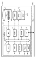
図2はレーザビームプリンタ1000における画像記録装置制御ユニット1001の構成を説明するブロック図である。
【0024】
なお、図2は本発明の記録ジョブファイルの制御方法をレーザビームプリンタに適用する例を示したものであり、レーザビームプリンタの代わりに例えばインクジェットプリンタなどの単体の機器、複数の機器からなるシステムあるいはLAN等のネットワークを介して処理が行われるシステムなどに適用してもよい。
画像記録装置制御ユニット1001において、1はCPUであり、2Aは制御プログラムを記憶するプログラムROMである。
【0025】
CPU1はプログラムROM2Aに記憶された制御プログラム等、あるいはハードディスク(HD)3に記憶され起動時にRAM4にロードされる制御プログラム等に基づいて、システムバス5に接続される各種のデバイスとのアクセスを総括的に制御する。またCPU1は、記録部インタフェース6を介して接続される記録部(プリンタエンジン)7に出力情報としての画像信号を出力する。
【0026】
プログラムROM2Bには、例えば、図4、図5、図6のフローチャートで示されるようなCPU1の制御プログラム等を記憶する。フォントROM2Bには上記出力情報を生成する際に使用するフォントデ−タ等を記憶する。
【0027】
CPU1はI/O8を介して、外部ネットワーク1500に接続されているホストコンピュータ等の外部機器(図示せず)との通信処理が可能である。なお、外部機器(図示せず)との通信を外部ネットワーク1500を介して行なうとしているが、直接インターフェース(図示せず)を介して外部機器(図示せず)と接続し、通信を行なっても良い。
【0028】
4はCPU12の主メモリ、ワークエリア等として機能するRAMで、増設ポートに接続されるオプションRAM(図示せず)によりメモリ容量を拡張することができるように構成されている。なお、RAM4は、出力情報展開領域、環境データ格納領域等にも用いられる。
【0029】
HD3は、メモリコントローラ(MC)9によりアクセスを制御される。HD3には、スプールジョブ、スプールイメージ、フォントデ−タ、エミュレ−ションプログラム、フォ−ムデ−タ等が記憶されている。
【0030】
1012は図1で説明した操作部であり、緊急処理など各種操作を実行するスイッチおよび異常状態などを表示するLED表示器等が配置されており、その状態は操作部コントローラ10により管理され制御される。
【0031】
11はLBP本体1000の電源オフ時にも、情報が保持される不揮発性メモリであるRAM(NVRAM)であり、操作部1012からのモード設定情報や起動時、リセット時または再起動時におけるブート処理で参照されるフラグ等を記憶している。
【0032】
12は現在時刻を常に更新し続けるTIMERであり、内部電池によりLBP本体1000の主電源OFF時にも現在時間を更新し続ける。
【0033】
なお、MC9は、HD3以外にもPCカードメモリ等の外部メモリ(図示せず)を少くとも1個以上接続出来るように構成し、内蔵フォントに加えてオプションフォントカード、言語系の異なるプリンタ制御言語を解釈するプログラム(エミュレ−ションプログラム)を格納した外部メモリ(図示せず)を複数接続できるように構成しても良い。
【0034】
[記録ジョブファイルの制御]
図3〜図6に示すフローチャートを用いて、記録ジョブファイルの制御方法および記録ジョブファイルのブート処理について説明する。
【0035】
図3に一例を示すように、HD3上には階層構造のディレクトリを有するファイルシステムが構築されている。
【0036】
図3において、301は、/(ルートディレクトリ)であり、302と303はルートディレクトリの直下にあるSPOOLディレクトリおよびIMAGEディレクトリである。
【0037】
SPOOLディレクトリ302には、HD3にスプールされた記録ジョブがファイルとして格納されている。図3に示す例では、304と305に示すspooled job1およびspooled job2がHDスプールされた記録ジョブファイルである。
LBP本体1000は、操作部1012又は外部ネットワーク1500上の外部機器(図示せず)から通知された指示により、動作モードとして、HDスプールモードか否かが設定される、また、上記の方法により設定された動作モードは、NVRAM11上に記録される。
【0038】
次に、上記動作モードがHDスプールモードに設定されているときのLBP本体1000の基本動作について以下説明する。
LBP本体1000ではネットワーク監視タスクが動作しており、外部ネットワーク1500からI/O8を介して記録ジョブが通知されると、HD3上に作成されているファイルシステムの/(ルートディレクトリ)301の直下のSPOOLディレクトリ302に記録ジョブファイル(以下/SPOOLディレクトリ302と記載する)として例えば、304に示すspooled job1として記録ジョブデータを書き込む。
また、LBP本体1000上では上述したネットワーク監視タスクとは独立した記録ジョブファイル処理タスクが動作している。
【0039】
[記録ジョブファイル処理タスクの動作]
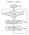
次に、図4のフローチャートにしたがって、通常の記録ジョブファイル処理タスクの動作について説明する。
【0040】
まずステップS402では、HD3の/SPOOLディレクトリ302を監視し、HDスプールされた記録ジョブファイルが検知されるまで待機し、HDスプールされた記録ジョブファイルを検知するとステップS403に進む。
【0041】
ステップS403では、検知した記録ジョブファイルの解析を行ない、記録ジョブファイルに含まれるデータに従って記録処理を行なう。記録ジョブファイルの全データの処理が正常に終了したら、ステップS404へ進む。
【0042】
ステップS404では、ステップS403で処理の終了したHD3上のHDスプールされた記録ジョブファイルを削除し、再びステップS402へ戻り、記録ジョブファイルが検知されるまで待機する。
【0043】
[ブート処理タスクの動作]
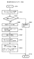
続いて、LBP本体1000の電源投入時、リセット時あるいは機器の異常動作時において実行されるブート処理における記録ジョブファイルの除去方法について、図5のフローチャートを参照して説明する。
【0044】
まずステップS501で、ブート処理を開始する。
【0045】
次にステップS502において、ハードウェアのチェックプログラムを起動してハードウェアに異常がないか否かをチェックしてからステップS503に進む。
【0046】
ステップS503では、ハードウェアに異常がある場合にはステップS504に進み、ハードウェアに異常があることを表示してから一連の作業を終了し、ハードウェアに異常がない場合にはステップS506に進む。
【0047】
ステップS506では、LBP本体1000上の各種デバイスの初期化を行ないってからステップS507に進み、ステップS507でCPU1で動作する基本OSの各種初期化を行ない基本OSを起動させてから、ステップS508へ進む。
【0048】
ステップS508では、ステップS507で起動した基本OSによって後述するHDスプール初期化タスクを生成し起動させた後にステップS509へ進む。
【0049】
ステップS509では、ステップS507で起動した基本OSによって、LBP本体1000上で動作する前述のネットワーク監視タスク、記録ジョブファイル処理タスク等のアプリケーションタスクを生成、起動してアプリケーションに処理を移行してからステップS505に進み一連の作業を終了する。
【0050】
[HDスプール初期化タスクの動作]
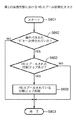
次に、図5のステップS508で生成、起動されるHDスプール初期化タスク処理の動作について、図6のフローチャートに従って説明する。
【0051】
ステップS601において、HDスプール初期化タスクが起動されると、ステップS602に進みHD3の/SPOOL302ディレクトリ上に記録ジョブファイルが存在するか否かを検索する。
【0052】
ステップS602において、/SPOOL302ディレクトリ上に記録ジョブファイルが存在しなければ、なにもせずにステップS604に進み、一連の作業を終了する。
【0053】
一方ステップS602において、/SPOOL302ディレクトリ上に記録ジョブファイルが存在する場合には、ステップS603に進み、/SPOOL302ディレクトリ上の記録ジョブファイルをすべて削除してから、ステップS604に進み、一連の作業を終了する。
以上説明したように、第1実施形態によれば、ブート処理時にHD3にスプールされている記録ジョブファイルは、記録ジョブファイル処理タスクで処理される前に、HDスプール初期化タスクで削除される。
【0054】
したがって、たとえHDスプールされた記録ジョブファイルにリブートの原因が存在する場合であっても、上記処理をすることによりHDスプールされた記録ジョブファイルに起因するリブート処理が繰り返されることはなくなる。
【0055】
[第2の実施形態]
本発明に係る第2の実施形態である記録ジョブファイルの制御方法について以下説明する。
【0056】
最初に、第2の実施形態である記録ジョブファイルの制御方法を実行する本発明の画像記録装置に係る一実施形態のレーザビームプリンタ、その画像記録装置制御ユニットの構成および階層構造のディレクトリを有するハードディスク(HD)について説明する。
【0057】
第2の実施形態である記録ジョブファイルの制御方法を実行するレーザビームプリンタ2000の構成は、図1で説明した第1の実施形態のレーザビームプリンタ1000の構成と同じである。また同様にして画像記録装置制御ユニット2001の構成は、図2で説明した第1の実施形態の画像記録装置制御ユニット1001の構成と同じである。したがって、以下の説明では重複するのでその説明は省略する。
【0058】
なお上記構成の第2の実施形態のレーザビームプリンタ2000では、更にレーザビームプリンタ2000の動作中に異常が発生すると発生した異常を処理するための異常処理用スイッチが操作部1012に設置されており、またそのスイッチが押下されたか否かを検出して報知する報知機能も操作部1012に追加設置されている。
【0059】
次に、第2の実施形態における階層構造のディレクトリを有するハードディスク(HD)3のファイルシステムおよび通常の記録ジョブファイル処理タスクの動作について説明する。
【0060】
第2の実施形態における階層構造のディレクトリを有するハードディスク(HD)3のファイルシステムは、図3で説明した第1の実施形態の階層構造のディレクトリと同じである。また同様にして第2の実施形態における通常の記録ジョブファイル処理タスクの動作は、図4で説明した通常の記録ジョブファイル処理タスクの動作と同じである。したがって、以下の説明では重複するのでその説明は省略する。
【0061】
次に、第2の実施形態におけるブート処理およびHDスプール初期化タスクの処理の動作について説明する。
【0062】
図7は、ブート処理を示すフローチャートであり、図8は第2実施形態におけるHDスプール初期化タスクの処理を示すフローチャートである。
【0063】
なお、図7および図8のフローチャートの説明においては、第1の実施形態におけるブート処理(図5)およびHDスプール初期化タスクの処理(図6)の動作で説明した各ステップの処理と同じ処理が存在する。そこで図7および図8のフローチャートでは、図5または図6に示すステップと共通するステップの処理には、同じステップの処理番号を付してその説明を省略することとし、以下に第1の実施形態と第2の実施形態の違いについて詳しく説明する。
【0064】
図7のステップS701において、ブート処理を開始すると、ステップS502に進む。
【0065】
ステップS502〜ステップS504の処理は図5で説明した処理と同一の処理であり、ハードウェアのチェックプログラムを起動してハードウェアに異常があった場合の異常警報表示の処理である。
【0066】
一方、ステップS502においてハードウェアに異常が無い場合にはステップS506に進み、各種デバイスの初期化を行なってからステップS702に進み、操作部1012の状態をチェックしてからステップS507に進む。
【0067】
すなわち、第1の実施形態ではステップS506で各種デバイスの初期化を終了した後直ちにステップS507へ進んだが、第2の実施形態ではステップS702へ進むように変更し、ステップS702でCPU1は操作部コントローラ10と通信を行ない、ブート時の操作部1012に設置されている各種スイッチの状態をRAM4上に記憶させてからステップS507へ進むように変更する。
【0068】
次に、ステップS507、ステップS703およびステップS509の処理を実行してからステップS510において一連の作業を終了する。
【0069】
なお、ステップS507およびステップS509の処理は図5で説明した処理と同一のブート処理であり、CPU1で動作する基本OSの各種初期化を行ない基本OSを起動させ図8を用いて後述するHDスプール初期化タスクを生成し起動させた後に、ネットワーク監視タスク、記録ジョブファイル処理タスク等のアプリケーションタスクを生成し起動してアプリケーションに処理を行う。
【0070】
次に、ステップS703に示す第2実施形態のHDスプール初期化タスクの動作について図8のフローチャートを用いて説明する。
【0071】
ステップS801において、HDスプール初期化タスクが起動されると、ステップS802に進み、図7のステップS702でRAM4上に記憶されているブート時の操作部1012の各種スイッチの状態を調べる。ここで、操作部1012の各種スイッチのうちの例えば緊急処理を行う「5」のキーが押されているか否かを調べる。
【0072】
ステップS802において、緊急処理を行う「5」のキーが押されていない場合にはステップS802に進み一連の作業を終了するが、緊急処理を行う「5」のキーが押されている場合にはステップS602に進む。
【0073】
ステップS602およびステップS603の処理は、図6で説明した処理と同一の処理であり、/SPOOL302ディレクトリ上の記録ジョブファイルの有無を調べ、記録ジョブファイルが存在する場合にのみ/SPOOL302ディレクトリ上の記録ジョブファイルをすべて削除する処理を行う。
【0074】
以上説明したように、第2実施形態では、ブート時の操作部1012の状態、すなわち緊急処理を行う特定のスイッチ(例えば「5」のキー)が押されているか否かを調べることによりHDスプールデータの削除の可否を決定する。
【0075】
なお、上記第2の実施形態の説明では、ステップS802では「5」のキーのキーが押されているか否かを調べているが、「5」のキーに限定されるものではなく、他のキーの状態で判断しても良い。また1つのキーの状態によって判断するのではなく、例えば、「2」のキーと「5」のキーが同時に押されていた場合にのみステップS802の条件を「YES」とするように、複数のキーの状態を組み合わせて判断するようにしてもよい。
【0076】
またさらに、上記第2の実施形態の説明では、ステップS702で操作部1012の状態を記憶し、ステップS802でその状態を判別するとしているが、ステップS802の処理の中で操作部コントローラ10と通信を行うように変更し、通信によって得た操作部1012の状態から緊急処理を行ったか否かの判別を行なうようにしても良い。
【0077】
[第3の実施形態]
本発明に係る第3の実施形態である記録ジョブファイルの制御方法について以下説明する。
【0078】
最初に、第3の実施形態である記録ジョブファイルの制御方法を実行する本発明の画像記録装置に係る一実施形態のレーザビームプリンタ、その画像記録装置制御ユニットの構成および階層構造のディレクトリを有するハードディスク(HD)について説明する。
【0079】
第3の実施形態である記録ジョブファイルの制御方法を実行するレーザビームプリンタ3000の構成は、図1で説明した第1の実施形態のレーザビームプリンタ1000の構成と同じである。また同様にして画像記録装置制御ユニット3001の構成は、図2で説明した第1の実施形態の画像記録装置制御ユニット1001の構成と同じである。したがって、以下の説明では重複するのでその説明は省略する。
【0080】
なお上記構成の第3の実施形態のレーザビームプリンタ3000には、更にレーザビームプリンタ3000が動作中に異常が発生すると、発生した異常を検出し、その異常内容に応じたサービスコールIDをNVRAM11上に格納する機能が追加されている。
【0081】
すなわちハードディスク3に格納した記録ジョブファイルの処理時に発生したメモリオーバー、異常命令、ダウンロードオーバーフロー、フォーマット不正などの異常の有無を検出し、もしも上記異常を検出した場合にはその異常内容に応じたサービスコールIDをNVRAM11に格納する。
【0082】
同様にして、エンジン、定着器、電源、回転多面鏡に設置してある各センサからエンジン、定着器、電源、回転多面鏡に起因する異常の有無を検出し、もしも上記異常を検出した場合にはその異常内容に応じたサービスコールIDをNVRAM11に格納する。
【0083】
次に、第3の実施形態における階層構造のディレクトリを有するハードディスク(HD)3のファイルシステムおよび通常の記録ジョブファイル処理タスクの動作について説明する。
【0084】
第3の実施形態における階層構造のディレクトリを有するHD3のファイルシステムは、図3で説明した第1の実施形態の階層構造のディレクトリと同じである。また同様にして第3の実施形態における通常の記録ジョブファイル処理タスクの動作は、図4で説明した通常の記録ジョブファイル処理タスクの動作と同じである。したがって、以下の説明では重複するのでその説明は省略する。
【0085】
次に、第3の実施形態におけるブート処理およびそのサブルーチンであるHDスプール初期化タスクの処理の動作について説明する。
【0086】
第3の実施形態におけるブート処理は、図5で説明した第1の実施形態のブート処理を示すフローチャートとステップS509に示すHDスプール初期化タスクのサブルーチン処理以外は同じである。したがって、以下の説明では重複するブート処理の説明は省略し、図9に示すフローチャートを用いて、第3の実施形態であるHDスプール初期化タスクの処理の動作についてのみ説明する。
【0087】
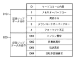
図10にNVRAM11に記述されるサービスコールIDの一例を示す。サービスコールIDとしては、910に示す記録ジョブファイルデータに依存して発生するサービスコールID、920に示す記録ジョブファイルデータに依存しないで発生するサービスコールIDに分類することができる。
【0088】
なお図10はサービスコールIDの一例を示したものであり、その内容が図10と異なる他のサービスコールIDであっても良い。
【0089】
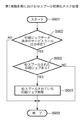
次に、第3の実施形態におけるHDスプール初期化タスクの動作について図9のフローチャートに従い説明する。
【0090】
まずステップS901において、HDスプール初期化タスクが起動されると、ステップS902に進み、NVRAM11に、図10に示した記録ジョブデータを原因とするサービスコールIDが記憶されているか否かを検索し、記録ジョブデータを原因とするサービスコールID(1〜4)が検出された場合にはステップS602に進んでその処理を行い、一方NVRAM11上で記録ジョブデータを原因とするサービスコールIDが検出されない場合にはステップS903に進み一連の作業を終了する。
【0091】
ステップS602およびステップS603の処理は、図6で説明した処理と同一の処理であり、/SPOOL302ディレクトリ上の記録ジョブファイルの有無を調べ、記録ジョブファイルが存在する場合にのみ/SPOOL302ディレクトリ上の記録ジョブファイルをすべて削除する処理を行い、記録ジョブファイルがなければなにもせずにその作業を終了する。
【0092】
以上説明したように、第3実施形態では、ブート時に不揮発メモリであるNVRAM11に記憶されているサービスコールの種類に応じてHDスプールデータの削除の可否を決定する。
【0093】
[第4の実施形態]
本発明に係る第4の実施形態である記録ジョブファイルの制御方法について以下説明する。
【0094】
最初に、第4の実施形態である記録ジョブファイルの制御方法を実行する本発明の画像記録装置に係る一実施形態のレーザビームプリンタ、その画像記録装置制御ユニットの構成および階層構造のディレクトリを有するハードディスク(HD)について説明する。
【0095】
第4の実施形態である記録ジョブファイルの制御方法を実行するレーザビームプリンタ4000の構成は、図1で説明した第1の実施形態のレーザビームプリンタ1000の構成と同じである。また同様にして画像記録装置制御ユニット4001の構成は、図2で説明した第1の実施形態の画像記録装置制御ユニット1001の構成と同じである。したがって、以下の説明では重複するのでその説明は省略する。
【0096】
なお上記構成の第4の実施形態のレーザビームプリンタ4000には、更にレーザビームプリンタ4000のブート処理時の時刻を検出し、検出した時刻をNVRAM11に格納する機能およびNVRAM11に格納された前回のブート処理時の時刻と今回のブート処理時の時刻の差を検出してその差が所定時間より小さいか否かを検出する機能が追加されている。
【0097】
次に、第4の実施形態における階層構造のディレクトリを有するハードディスク(HD)のファイルシステムおよび通常の記録ジョブファイル処理タスクの動作について説明する。
【0098】
第4の実施形態における階層構造のディレクトリを有するハードディスク(HD)のファイルシステムは、図3で説明した第1の実施形態の階層構造のディレクトリと同じである。また同様にして第2の実施形態における通常の記録ジョブファイル処理タスクの動作は、図4で説明した通常の記録ジョブファイル処理タスクの動作と同じである。したがって、以下の説明では重複するのでその説明は省略する。
【0099】
次に、第4の実施形態におけるブート処理およびそのサブルーチンであるHDスプール初期化タスクの処理の動作について説明する。
【0100】
第4の実施形態におけるブート処理は、図5で説明した第1の実施形態のブート処理を示すフローチャートとステップS509に示すHDスプール初期化タスクのサブルーチン処理以外は同じである。したがって、以下の説明では重複するブート処理の説明は省略し、図11に示すフローチャートを用いて、第4の実施形態であるHDスプール初期化タスクの処理の動作についてのみ説明する。
【0101】
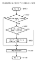
まずステップS1001においてHDスプール初期化タスクを起動すると、ステップS1002に進み、TIMER12から現在時刻を取得し、後述するステップ1003でNVRAM11上に格納してある「前回ブート時刻」との差分をとる。
【0102】
ステップS1002において、「現在時刻」-「前回ブート時刻」が予め設定されているT1より小さければ、ステップ602へ進み前述のステップS602およびステップS603の処理、すなわち、/SPOOL302ディレクトリ上の記録ジョブファイルの有無を調べ、記録ジョブファイルが存在する場合にのみ/SPOOL302ディレクトリ上の記録ジョブファイルをすべて削除する処理を行ってからステップS1003に進む。なおT1の値はディフォルト値として20秒とするが任意に設定することができる。
【0103】
一方ステップS1002において、「現在時刻」-「前回ブート時刻」がT1以上の場合には、なにもしないでステップS1003へ進む。
【0104】
ステップS1003ではTIMER12から現在時刻を取得し、NVRAM11上に記憶された前回のブート時の時刻に上書きしてから、ステップS1004に進み一連の処理を終了する。
【0105】
以上説明したように、第4実施形態では、リブート間の時間に応じてHDスプールデータの削除の可否を決定する。
【0106】
以上説明した各実施形態によれば、起動時、リセット時または異常動作などに実施するブート処理において、画像記録装置内のハードディスクなどにスプールされている記録ジョブファイルをすべて削除することにより、ハードディスクなどにスプールされた記録ジョブが原因となって繰り返し引き起こす障害の発生を防止することができる。
【他の実施形態】
なお本発明は、複数の機器(例えばホストコンピュータ、インタフェイス機器、リーダ、画像記録装置など)から構成されるシステムに適用しても一つの機器からなる装置(例えば、複写機、ファクシミリ装置など)に適用してもよい。
【0107】
また、本発明の目的は、前述した実施形態の機能を実現するソフトウェアのプログラムコードを記録した記憶媒体(または記録媒体)を、システムあるいは装置に供給し、そのシステムあるいは装置のコンピュータ(またはCPUやMPU)が記憶媒体に格納されたプログラムコードを読み出し実行することによっても、達成されることは言うまでもない。この場合、記憶媒体から読み出されたプログラムコード自体が前述した実施形態の機能を実現することになり、そのプログラムコードを記憶した記憶媒体は本発明を構成することになる。また、コンピュータが読み出したプログラムコードを実行することにより、前述した実施形態の機能が実現されるだけでなく、そのプログラムコードの指示に基づき、コンピュータ上で稼働しているオペレーティングシステム(OS)などが実際の処理の一部または全部を行い、その処理によって前述した実施形態の機能が実現される場合も含まれることは言うまでもない。
【0108】
さらに、記憶媒体から読み出されたプログラムコードが、コンピュータに挿入された機能拡張カードやコンピュータに接続された機能拡張ユニットに備わるメモリに書込まれた後、そのプログラムコードの指示に基づき、その機能拡張カードや機能拡張ユニットに備わるCPUなどが実際の処理の一部または全部を行い、その処理によって前述した実施形態の機能が実現される場合も含まれることは言うまでもない。
【0109】
本発明を上記記憶媒体に適用する場合、その記憶媒体には、先に説明した(図4〜図9および図11に示す)フローチャートに対応するプログラムコードが格納されることになる。
【0110】
【発明の効果】
以上説明したように本発明によれば、起動時、リセット時または異常動作時などに実施するブート処理において、メモリにスプールされた記録ジョブが原因となって引き起こす障害の発生を防止する画像記録装置の制御方法および画像記録装置を提供できる。
【図面の簡単な説明】
【図1】本発明に係る一実施形態のレーザビームプリンタの構成を示す断面図である。
【図2】 本発明に係る一実施形態の記録ジョブファイルの制御をレーザビームプリンタに適用する場合の構成を説明するブロック図である。
【図3】本発明に係る一実施形態のハードディスク上に格納されたファイルの論理構成を示す概念図である。
【図4】本発明に係る一実施形態の記録ジョブ処理タスクの動作を説明するフローチャートである。
【図5】本発明に係る第1の実施形態におけるブート処理時の動作を説明するフローチャートである。
【図6】本発明に係る第1の実施形態におけるHDスプール初期化タスク処理の動作を説明するフローチャートである。
【図7】本発明に係る第2の実施形態におけるブート処理時の動作を説明するフローチャートである。
【図8】本発明に係る第2の実施形態におけるHDスプール初期化タスクの動作を説明するフローチャートである。
【図9】本発明に係る第3の実施形態におけるHDスプール初期化タスクの動作を説明するフローチャートである。
【図10】本発明に係る第3の実施形態におけるサービスコールの内容を説明する一例である。
【図11】本発明に係る第4の実施形態におけるHDスプール初期化タスクの動作を説明するフローチャートである。
【符号の説明】
1 CPU
2A プログラムROM
2B フォントROM
3 HD(ハードディスク)
4 RAM
5 バス
6 記録部I/F
7 記録部
8 I/O
9 MC(メモリコントローラ)
10 操作部コントローラ
11 NVRAM
12 TIMER
1000 画像記録装置
1012 操作部
1500 外部ネットワーク[0001]
BACKGROUND OF THE INVENTION
The present invention relates to an image recording apparatus control method, an image recording apparatus, and a storage medium.
[0002]
[Prior art]
In recent years, an image recording apparatus that receives and records a recording job from a host computer spools (temporarily) all the recording jobs received in the large-capacity memory of the image recording apparatus in order to quickly release the host computer from the recording process. It has a function of performing data analysis for recording after it is stored as a file.
[0003]
The above function generally uses a hard disk (HD) as a large-capacity memory, and is called an HD spool function.
[Problems to be solved by the invention]
Incidentally, a serious failure may occur in the image recording apparatus during processing of a recording job spooled using the HD spool function. In this case, after the trouble of the normal image recording apparatus is solved, it is restarted and the boot process is performed. In this boot process, the spooled recording job is also processed again.
[0004]
However, in the above-described reprocessing, if there is a cause of a failure in the spooled recording job, the recording job is reprocessed every time the boot process is performed, so that the failure occurs again. Has the problem of repeating the boot process endlessly.
[0005]
The present invention has been made to solve the above-described problems of the prior art, and the object thereof is spooled in a memory during boot processing performed at startup, reset, or abnormal operation. An object of the present invention is to provide an image recording apparatus control method and an image recording apparatus capable of preventing the occurrence of a failure caused by a recording job.
[Means for Solving the Problems]
In order to achieve the above object, an image recording apparatus control method according to an embodiment of the present invention includes the following arrangement. That is, when an abnormality occurs in the spool process for spooling the print job file to the hard disk drive of the image recording apparatus and the processing of the print job file spooled in the spool process, the abnormality is detected in the spooled print job file. In the specifying step for determining whether or not the print job file is caused, and in the boot process of the image recording apparatus, a print job file is spooled in the hard disk drive, and the abnormality is caused by the print job file in the specifying step. If it is specified, the print job file spooled in the hard disk drive is deleted.
When the print job file is spooled in the hard disk drive and the abnormality is determined not to be caused by the spooled print job file in the specifying step, the spooled file is spooled in the hard disk drive. Leave print job fileAnd a print job file deleting step.
[0006]
For example, it is preferable that the boot process is executed when the image recording apparatus is activated, reset, or abnormally operated.
[0008]
Also, for example,Specific processIs one of memory overflow, abnormal instruction, download overflow, and format illegalIf the error occurs, it is determined that the abnormality is caused by the spooled print job file.It is preferable.
[0009]
The image recording apparatus control method according to the present invention includes a spool process for spooling a print job file to the hard disk drive of the image recording apparatus, a current time at the time of boot processing of the image recording apparatus, and a time at the previous boot process. A determination step for determining whether or not the difference in time is smaller than a predetermined time, and the difference between the current time at the boot processing of the image recording apparatus and the time at the previous boot processing in the determination step is smaller than the predetermined time And the print job file spooled in the hard disk drive is deleted when it is detected that the print job file is spooled in the hard disk drive in the boot process of the image recording apparatus.In the determination step, the difference between the current time at the boot process of the image recording apparatus and the time at the previous boot process is not determined to be smaller than a predetermined time, and the boot process of the image recording apparatus When it is detected that the print job file is spooled in the hard disk drive, the print job file spooled in the hard disk drive is left.And a print job file deletion step.
For example, it is preferable that the boot process is executed when the image recording apparatus is activated, reset, or abnormally operated.
[0010]
The image recording apparatus according to the present invention also includes a spool unit that spools a print job file to a hard disk drive of the image recording apparatus, and the abnormality occurs when an abnormality occurs in the processing of the print job file spooled by the spool unit. A specifying means for specifying whether or not the print job file is caused; and in the boot process of the image recording apparatus, a print job file is spooled in the hard disk drive, and the abnormality is printed by the specifying means. Deletes the print job file spooled in the hard disk drive when it is determined to be caused by the job fileWhen the print job file is spooled in the hard disk drive and the abnormality is determined not to be caused by the spooled print job file in the specifying step, the spooled file is spooled in the hard disk drive. Leave print job fileAnd a print job file deleting means.
In the image recording apparatus of the present invention, the spool means for spooling the print job file to the hard disk drive of the image recording apparatus, and the difference between the current time at the boot process of the image recording apparatus and the time at the previous boot process is predetermined. A determination means for determining whether or not the time is less than a predetermined time, and the determination means determines that the difference between the current time at the boot processing of the image recording apparatus and the time at the previous boot processing is smaller than a predetermined time, In addition, when it is detected in the boot process that the print job file is spooled in the hard disk drive, the print job file spooled in the hard disk drive is deleted.The determination means does not determine that the difference between the current time during the boot process of the image recording apparatus and the time during the previous boot process is smaller than a predetermined time, and the boot process of the image recording apparatus When it is detected that the print job file is spooled in the hard disk drive, the print job file spooled in the hard disk drive is left.And a print job file deleting means.
[0011]
The computer-readable storage medium of the present invention stores a computer program for causing a computer to execute the method for controlling an image recording apparatus according to any one of
[0012]
It should be noted that the image recording apparatus to which the present embodiment is applied is not limited to the laser beam printer and the inkjet image recording apparatus, and needless to say, an image recording apparatus of another image recording method may be used. Further, it goes without saying that the image recording apparatus to which the present embodiment is applied is not limited to one that operates as a single image recording apparatus, but can be applied to a composite image recording apparatus having both a copy function and a FAX function.
[0013]
[First Embodiment]
A recording job file control method according to the first embodiment of the present invention will be described below. First, the configuration of a laser beam printer and an image recording apparatus control unit according to an embodiment of the image recording apparatus of the present invention that executes the recording job file control method according to the first embodiment will be described.
[0014]
The recording job file control method described above is to check the recording job file remaining in the hard disk during the boot process, and if there is an unprocessed recording job file, the recording job file is regarded as an abnormal operation of the image recording apparatus. It is a control method that deletes it as a cause. With this control method, it is possible to prevent an abnormal operation repeatedly caused by the recording job file every time the boot process is performed and the boot process associated therewith.
[0015]
[Laser beam printer body]
FIG. 1 is a cross-sectional view showing a configuration of a laser beam printer (LBP).
In FIG. 1,
[0016]
An
[0017]
The image recording
[0018]
The
[0019]
As this recording paper, for example, a cut sheet is used. The cut sheet recording paper is stored in a
[0020]
Then, the toner image attached on the
[0021]
In addition, the LBP
[0022]
The developing
[0023]
[Configuration of Image Recording Device Control Unit]
FIG. 2 is a block diagram illustrating the configuration of the image recording
[0024]
FIG. 2 shows an example in which the recording job file control method of the present invention is applied to a laser beam printer. Instead of a laser beam printer, for example, a system comprising a single device such as an inkjet printer or a plurality of devices. Alternatively, the present invention may be applied to a system in which processing is performed via a network such as a LAN.
In the image recording
[0025]
The
[0026]
In the
[0027]
The
[0028]
[0029]
Access to the
[0030]
[0031]
[0032]
[0033]
In addition to the HD3, the MC9 is configured so that at least one external memory (not shown) such as a PC card memory can be connected. In addition to the built-in font, an optional font card and a printer control language with a different language system are used. A plurality of external memories (not shown) storing a program (emulation program) for interpreting the above may be connected.
[0034]
[Control of recording job file]
A recording job file control method and a recording job file boot process will be described with reference to flowcharts shown in FIGS.
[0035]
As shown in FIG. 3 as an example, a file system having a hierarchical directory is constructed on the
[0036]
In FIG. 3, 301 is / (root directory), and 302 and 303 are SPOOL directory and IMAGE directory directly under the root directory.
[0037]
The
The LBP
[0038]
Next, the basic operation of the LBP
In the LBP
On the LBP
[0039]
[Operation of recording job file processing task]
Next, the operation of a normal recording job file processing task will be described with reference to the flowchart of FIG.
[0040]
First, in step S402, the /
[0041]
In step S403, the detected recording job file is analyzed, and recording processing is performed according to the data included in the recording job file. If the processing of all the data of the recording job file is completed normally, the process proceeds to step S404.
[0042]
In step S404, the HD-spooled recording job file on HD3 that has been processed in step S403 is deleted, the process returns to step S402 again, and waits until a recording job file is detected.
[0043]
[Boot process task operation]
Next, a recording job file removal method in boot processing executed when the LBP
[0044]
First, in step S501, boot processing is started.
[0045]
Next, in step S502, a hardware check program is activated to check whether there is any abnormality in the hardware, and then the process proceeds to step S503.
[0046]
In step S503, if there is an abnormality in the hardware, the process proceeds to step S504. After displaying that there is an abnormality in the hardware, a series of operations is terminated. If there is no abnormality in the hardware, the process proceeds to step S506. .
[0047]
In step S506, various devices on the LBP
[0048]
In step S508, an HD spool initialization task (to be described later) is generated and started by the basic OS started in step S507, and the process proceeds to step S509.
[0049]
In step S509, the basic OS started in step S507 generates application tasks such as the aforementioned network monitoring task and recording job file processing task that operate on the LBP
[0050]
[Operation of HD spool initialization task]
Next, the operation of the HD spool initialization task process generated and activated in step S508 of FIG. 5 will be described with reference to the flowchart of FIG.
[0051]
When the HD spool initialization task is activated in step S601, the process advances to step S602 to search whether a recording job file exists in the /
[0052]
In step S602, if the recording job file does not exist in the /
[0053]
On the other hand, if a recording job file exists in the / SPOOL302 directory in step S602, the process proceeds to step S603, and all the recording job files in the / SPOOL302 directory are deleted, and then the process proceeds to step S604 to complete a series of operations. To do.
As described above, according to the first embodiment, the recording job file spooled in the
[0054]
Therefore, even if there is a cause for reboot in the recording job file spooled in HD, the reboot processing due to the recording job file spooled in HD is not repeated by performing the above processing.
[0055]
[Second Embodiment]
A recording job file control method according to the second embodiment of the present invention will be described below.
[0056]
First, the laser beam printer according to an embodiment of the image recording apparatus of the present invention that executes the recording job file control method according to the second embodiment, the configuration of the image recording apparatus control unit, and the hierarchical structure directory are included. The hard disk (HD) will be described.
[0057]
The configuration of the laser beam printer 2000 that executes the recording job file control method according to the second embodiment is the same as the configuration of the
[0058]
In the laser beam printer 2000 of the second embodiment configured as described above, an operation processing switch is provided in the
[0059]
Next, the operation of the file system of the hard disk (HD) 3 having a hierarchical directory and the normal recording job file processing task in the second embodiment will be described.
[0060]
The file system of the hard disk (HD) 3 having the hierarchical directory in the second embodiment is the same as the hierarchical directory in the first embodiment described in FIG. Similarly, the operation of the normal recording job file processing task in the second embodiment is the same as the operation of the normal recording job file processing task described in FIG. Therefore, since it overlaps in the following description, the description is abbreviate | omitted.
[0061]
Next, the boot processing and HD spool initialization task processing operations in the second embodiment will be described.
[0062]
FIG. 7 is a flowchart showing the boot process, and FIG. 8 is a flowchart showing the process of the HD spool initialization task in the second embodiment.
[0063]
In the description of the flowcharts of FIGS. 7 and 8, the same processing as the processing of each step described in the operations of the boot processing (FIG. 5) and the HD spool initialization task processing (FIG. 6) in the first embodiment. Exists. Therefore, in the flowcharts of FIG. 7 and FIG. 8, the processing steps common to the steps shown in FIG. 5 or FIG. The difference between the embodiment and the second embodiment will be described in detail.
[0064]
When the boot process is started in step S701 in FIG. 7, the process proceeds to step S502.
[0065]
The processing from step S502 to step S504 is the same processing as that described in FIG. 5, and is a processing for displaying an alarm when a hardware check program is started and there is a hardware abnormality.
[0066]
On the other hand, if there is no abnormality in the hardware in step S502, the process proceeds to step S506. After initializing various devices, the process proceeds to step S702, and after checking the state of the
[0067]
That is, in the first embodiment, the process proceeds to step S507 immediately after the initialization of various devices in step S506. However, in the second embodiment, the process proceeds to step S702. In step S702, the
[0068]
Next, after executing the processing of step S507, step S703, and step S509, a series of work is ended in step S510.
[0069]
Note that the processing in step S507 and step S509 is the same boot processing as the processing described in FIG. 5, and performs various initializations of the basic OS operating on the
[0070]
Next, the operation of the HD spool initialization task of the second embodiment shown in step S703 will be described using the flowchart of FIG.
[0071]
When the HD spool initialization task is started in step S801, the process proceeds to step S802, and the state of various switches of the
[0072]
In step S802, if the “5” key for performing the emergency process is not pressed, the process proceeds to step S802 to end the series of operations. If the “5” key for performing the emergency process is pressed, The process proceeds to step S602.
[0073]
The processes in steps S602 and S603 are the same as the processes described in FIG. 6, and the presence / absence of a recording job file on the / SPOOL302 directory is checked. Only when the recording job file exists, the recording on the / SPOOL302 directory is performed. Delete all job files.
[0074]
As described above, in the second embodiment, the HD spool is checked by checking the state of the
[0075]
In the description of the second embodiment, whether or not the key of the “5” key is pressed is checked in step S802. However, the key is not limited to the “5” key. You may judge by the state of a key. In addition, the determination is not made based on the state of one key. For example, only when the “2” key and the “5” key are pressed at the same time, the condition in step S802 is set to “YES”. You may make it judge combining the state of a key.
[0076]
Furthermore, in the description of the second embodiment, the state of the
[0077]
[Third Embodiment]
A recording job file control method according to the third embodiment of the present invention will be described below.
[0078]
First, the laser beam printer according to an embodiment of the image recording apparatus of the present invention that executes the recording job file control method according to the third embodiment, the configuration of the image recording apparatus control unit, and the hierarchical directory are included. The hard disk (HD) will be described.
[0079]
The configuration of the laser beam printer 3000 for executing the recording job file control method according to the third embodiment is the same as the configuration of the
[0080]
In the laser beam printer 3000 of the third embodiment having the above configuration, if an abnormality occurs while the laser beam printer 3000 is operating, the abnormality that has occurred is detected, and a service call ID corresponding to the content of the abnormality is stored on the
[0081]
In other words, it detects the presence or absence of abnormalities such as memory over, abnormal instructions, download overflows, format errors, etc. that occurred during processing of the recorded job file stored on the
[0082]
Similarly, if there is an abnormality due to the engine, fuser, power supply, and rotating polygon mirror from each sensor installed in the engine, fixing device, power supply, and rotating polygon mirror, and if the above abnormality is detected Stores the service call ID corresponding to the abnormal content in the
[0083]
Next, the operation of the file system of the hard disk (HD) 3 having a hierarchical directory and the normal recording job file processing task in the third embodiment will be described.
[0084]
The HD3 file system having a hierarchical directory in the third embodiment is the same as the hierarchical directory in the first embodiment described in FIG. Similarly, the operation of the normal recording job file processing task in the third embodiment is the same as the operation of the normal recording job file processing task described in FIG. Therefore, since it overlaps in the following description, the description is abbreviate | omitted.
[0085]
Next, the boot process and the operation of the HD spool initialization task process that is a subroutine of the third embodiment will be described.
[0086]
The boot processing in the third embodiment is the same except for the flowchart showing the boot processing of the first embodiment described in FIG. 5 and the subroutine processing of the HD spool initialization task shown in step S509. Therefore, in the following description, the description of the redundant boot process is omitted, and only the operation of the HD spool initialization task process according to the third embodiment will be described using the flowchart shown in FIG.
[0087]
FIG. 10 shows an example of the service call ID described in the
[0088]
FIG. 10 shows an example of the service call ID, and the content may be another service call ID different from that in FIG.
[0089]
Next, the operation of the HD spool initialization task in the third embodiment will be described with reference to the flowchart of FIG.
[0090]
First, when the HD spool initialization task is activated in step S901, the process advances to step S902 to search whether or not the service call ID caused by the recording job data shown in FIG. 10 is stored in the
[0091]
The processes in steps S602 and S603 are the same as the processes described in FIG. 6, and the presence / absence of a recording job file on the / SPOOL302 directory is checked. Only when the recording job file exists, the recording on the / SPOOL302 directory is performed. The process of deleting all job files is performed, and the operation is completed without any recording job file.
[0092]
As described above, in the third embodiment, whether or not HD spool data can be deleted is determined according to the type of service call stored in the
[0093]
[Fourth Embodiment]
A recording job file control method according to the fourth embodiment of the present invention will be described below.
[0094]
First, it has a laser beam printer according to an embodiment of the image recording apparatus of the present invention that executes the recording job file control method according to the fourth embodiment, a configuration of the image recording apparatus control unit, and a hierarchical directory. The hard disk (HD) will be described.
[0095]
The configuration of the laser beam printer 4000 that executes the recording job file control method according to the fourth embodiment is the same as the configuration of the
[0096]
The laser beam printer 4000 of the fourth embodiment configured as described above further detects the time at the time of boot processing of the laser beam printer 4000, stores the detected time in the
[0097]
Next, operations of a hard disk (HD) file system having a hierarchical directory and a normal recording job file processing task in the fourth embodiment will be described.
[0098]
The file system of the hard disk (HD) having a hierarchical directory in the fourth embodiment is the same as the hierarchical directory in the first embodiment described in FIG. Similarly, the operation of the normal recording job file processing task in the second embodiment is the same as the operation of the normal recording job file processing task described in FIG. Therefore, since it overlaps in the following description, the description is abbreviate | omitted.
[0099]
Next, the boot process and the HD spool initialization task process, which is a subroutine thereof, in the fourth embodiment will be described.
[0100]
The boot processing in the fourth embodiment is the same except for the flowchart showing the boot processing of the first embodiment described in FIG. 5 and the subroutine processing of the HD spool initialization task shown in step S509. Therefore, in the following description, the description of the redundant boot process is omitted, and only the operation of the HD spool initialization task process according to the fourth embodiment will be described using the flowchart shown in FIG.
[0101]
First, when the HD spool initialization task is activated in step S1001, the process proceeds to step S1002, where the current time is acquired from the
[0102]
In step S1002, if “current time” − “previous boot time” is smaller than T1, which is set in advance, the process proceeds to step 602, and the processing in steps S602 and S603 described above, that is, the recording job file in the /
[0103]
On the other hand, if “current time” − “previous boot time” is equal to or greater than T1 in step S1002, the process proceeds to step S1003 without doing anything.
[0104]
In step S1003, the current time is acquired from the
[0105]
As described above, in the fourth embodiment, whether or not the HD spool data can be deleted is determined according to the time between reboots.
[0106]
According to each of the embodiments described above, a hard disk or the like can be obtained by deleting all the recording job files spooled on the hard disk or the like in the image recording apparatus in the boot process performed at startup, reset, or abnormal operation. Thus, it is possible to prevent the occurrence of a failure repeatedly caused by a recording job spooled in the printer.
[Other Embodiments]
Note that the present invention can be applied to a system including a plurality of devices (for example, a host computer, an interface device, a reader, an image recording device, etc.), and a device (for example, a copier, a facsimile device, etc.) including a single device. You may apply to.
[0107]
Another object of the present invention is to supply a storage medium (or recording medium) in which a program code of software that realizes the functions of the above-described embodiments is recorded to a system or apparatus, and the computer (or CPU or CPU) of the system or apparatus. Needless to say, this can also be achieved by the MPU) reading and executing the program code stored in the storage medium. In this case, the program code itself read from the storage medium realizes the functions of the above-described embodiments, and the storage medium storing the program code constitutes the present invention. Further, by executing the program code read by the computer, not only the functions of the above-described embodiments are realized, but also an operating system (OS) running on the computer based on the instruction of the program code. It goes without saying that a case where the function of the above-described embodiment is realized by performing part or all of the actual processing and the processing is included.
[0108]
Furthermore, after the program code read from the storage medium is written into a memory provided in a function expansion card inserted into the computer or a function expansion unit connected to the computer, the function is determined based on the instruction of the program code. It goes without saying that the CPU or the like provided in the expansion card or the function expansion unit performs part or all of the actual processing and the functions of the above-described embodiments are realized by the processing.
[0109]
When the present invention is applied to the above storage medium, the storage medium stores program codes corresponding to the flowcharts described above (shown in FIGS. 4 to 9 and 11).
[0110]
【The invention's effect】
As described above, according to the present invention, an image recording apparatus that prevents the occurrence of a failure caused by a recording job spooled in a memory in a boot process performed at startup, reset, or abnormal operation is performed. Control method and image recording apparatus can be provided.
[Brief description of the drawings]
FIG. 1 is a cross-sectional view showing a configuration of a laser beam printer according to an embodiment of the present invention.
FIG. 2 is a block diagram illustrating a configuration in a case where control of a recording job file according to an embodiment of the present invention is applied to a laser beam printer.
FIG. 3 is a conceptual diagram showing a logical configuration of a file stored on a hard disk according to an embodiment of the present invention.
FIG. 4 is a flowchart illustrating an operation of a recording job processing task according to an embodiment of the present invention.
FIG. 5 is a flowchart illustrating an operation during boot processing in the first embodiment of the present invention.
FIG. 6 is a flowchart illustrating an operation of HD spool initialization task processing in the first embodiment according to the present invention.
FIG. 7 is a flowchart for explaining an operation at the time of boot processing in the second embodiment according to the present invention;
FIG. 8 is a flowchart illustrating the operation of an HD spool initialization task in the second embodiment according to the invention.
FIG. 9 is a flowchart illustrating an operation of an HD spool initialization task in the third embodiment according to the present invention.
FIG. 10 is an example for explaining the contents of a service call in the third embodiment according to the present invention.
FIG. 11 is a flowchart illustrating the operation of an HD spool initialization task in the fourth embodiment according to the invention.
[Explanation of symbols]
1 CPU
2A Program ROM
2B Font ROM
3 HD (hard disk)
4 RAM
5 Bus
6 Recording section I / F
7 Recording section
8 I / O
9 MC (memory controller)
10 Operation unit controller
11 NVRAM
12 TIMER
1000 Image recording device
1012 Operation unit
1500 external network
Claims (8)
前記スプール工程においてスプールされた前記印刷ジョブファイルの処理において異常が発生した場合に、前記異常が前記印刷ジョブファイルに起因するか否かを特定する特定工程と、
前記画像記録装置のブート処理において、前記ハードディスクドライブに印刷ジョブファイルがスプールされており、かつ、前記特定工程において前記異常が前記スプールされた印刷ジョブファイルに起因すると特定された場合に、前記ハードディスクドライブにスプールされている該印刷ジョブファイルを削除し、前記ハードディスクドライブに印刷ジョブファイルがスプールされており、かつ、前記特定工程において前記異常が前記スプールされた印刷ジョブファイルに起因しないと特定された場合に、前記ハードディスクドライブにスプールされている前記印刷ジョブファイルを残す印刷ジョブファイル削除工程と、
を有することを特徴とする画像記録装置の制御方法。A spooling process for spooling the print job file to the hard disk drive of the image recording device;
A specifying step for specifying whether or not the abnormality is caused by the print job file when an abnormality occurs in the processing of the print job file spooled in the spooling step;
In a boot process of the image recording apparatus, when a print job file is spooled in the hard disk drive and the abnormality is identified as being caused by the spooled print job file in the identifying step, the hard disk drive Is deleted , the print job file is spooled in the hard disk drive, and it is specified in the specifying step that the abnormality is not caused by the spooled print job file. A print job file deletion step for leaving the print job file spooled in the hard disk drive ;
A method for controlling an image recording apparatus, comprising:
前記画像記録装置のブート処理時の現時刻と前回のブート処理時の時刻との差が所定の時間より小さいか否かを判定する判定工程と、
前記判定工程において前記画像記録装置のブート処理時の現時刻と前回のブート処理時の時刻との差が所定の時間より小さいと判定され、かつ、前記画像記録装置のブート処理において前記ハードディスクドライブに前記印刷ジョブファイルがスプールされていると検知された場合に、前記ハードディスクドライブにスプールされている前記印刷ジョブファイルを削除し、前記判定工程において前記画像記録装置のブート処理時の現時刻と前回のブート処理時の時刻との差が所定の時間より小さいと判定されず、かつ、前記画像記録装置のブート処理において前記ハードディスクドライブに前記印刷ジョブファイルがスプールされていると検知された場合に、前記ハードディスクドライブにスプールされている前記印刷ジョブファイルを残す印刷ジョブファイル削除工程と、
を有することを特徴とする画像記録装置の制御方法。A spooling process for spooling the print job file to the hard disk drive of the image recording device;
A determination step of determining whether a difference between a current time at the time of boot processing of the image recording apparatus and a time at the time of the previous boot processing is smaller than a predetermined time;
In the determination step, it is determined that the difference between the current time at the boot processing of the image recording apparatus and the time at the previous boot processing is smaller than a predetermined time, and the hard disk drive is in the boot processing of the image recording apparatus. When it is detected that the print job file is spooled, the print job file spooled in the hard disk drive is deleted , and the current time and the previous time at the boot process of the image recording apparatus in the determination step are deleted . When it is not determined that the difference from the time at the time of boot processing is smaller than a predetermined time, and it is detected that the print job file is spooled in the hard disk drive in the boot processing of the image recording apparatus, leaving the print job file that is spooled on the hard disk drive And the printing job file deletion process,
A method for controlling an image recording apparatus, comprising:
前記スプール手段によってスプールされた前記印刷ジョブファイルの処理において異常が発生した場合に、前記異常が前記印刷ジョブファイルに起因するか否かを特定する特定手段と、
前記画像記録装置のブート処理において、前記ハードディスクドライブに印刷ジョブファイルがスプールされており、かつ、前記特定手段によって前記異常が前記印刷ジョブファイルに起因すると特定された場合に、前記ハードディスクドライブにスプールされている該印刷ジョブファイルを削除し、前記ハードディスクドライブに印刷ジョブファイルがスプールされており、かつ、前記特定工程において前記異常が前記スプールされた印刷ジョブファイルに起因しないと特定された場合に、前記ハードディスクドライブにスプールされている前記印刷ジョブファイルを残す印刷ジョブファイル削除手段と、
を有することを特徴とする画像記録装置。Spool means for spooling the print job file to the hard disk drive of the image recording device;
Specifying means for specifying whether or not the abnormality is caused by the print job file when an abnormality occurs in the processing of the print job file spooled by the spool means;
In a boot process of the image recording apparatus, when a print job file is spooled in the hard disk drive and the abnormality is identified by the specifying unit as being caused by the print job file, the image recording apparatus is spooled in the hard disk drive. When the print job file is spooled in the hard disk drive and the abnormality is determined not to be caused by the spooled print job file in the specifying step, Print job file deletion means for leaving the print job file spooled in the hard disk drive ;
An image recording apparatus comprising:
前記画像記録装置のブート処理時の現時刻と前回のブート処理時の時刻との差が所定の時間より小さいか否かを判定する判定手段と、
前記判定手段によって前記画像記録装置のブート処理時の現時刻と前回のブート処理時の時刻との差が所定の時間より小さいと判定され、かつ、前記ブート処理において前記ハードディスクドライブに前記印刷ジョブファイルがスプールされていると検知された場合に、前記ハードディスクドライブにスプールされている前記印刷ジョブファイルを削除し、前記判定手段において前記画像記録装置のブート処理時の現時刻と前回のブート処理時の時刻との差が所定の時間より小さいと判定されず、かつ、前記画像記録装置のブート処理において前記ハードディスクドライブに前記印刷ジョブファイルがスプールされていると検知された場合に、前記ハードディスクドライブにスプールされている前記印刷ジョブファイルを残す印刷ジョブファイル削除手段と、
を有することを特徴とする画像記録装置。Spool means for spooling the print job file to the hard disk drive of the image recording device;
Determining means for determining whether or not a difference between a current time at the time of boot processing of the image recording apparatus and a time at the time of the previous boot processing is smaller than a predetermined time;
The determination means determines that the difference between the current time at the boot processing of the image recording apparatus and the time at the previous boot processing is smaller than a predetermined time, and the print job file is stored in the hard disk drive in the boot processing. Is detected as being spooled, the print job file spooled in the hard disk drive is deleted , and the current time at the time of boot processing of the image recording apparatus and the time at the previous boot processing are deleted by the determination means. If it is not determined that the difference from the time is smaller than a predetermined time, and it is detected that the print job file is spooled in the hard disk drive in the boot process of the image recording apparatus, the spool is stored in the hard disk drive. printing Jobufa leaving the print job file is And Le deleting means,
An image recording apparatus comprising:
Priority Applications (4)
| Application Number | Priority Date | Filing Date | Title |
|---|---|---|---|
| JP2001055649A JP4454875B2 (en) | 2001-02-28 | 2001-02-28 | Image recording apparatus control method and image recording apparatus |
| US10/082,301 US7050183B2 (en) | 2001-02-28 | 2002-02-26 | Image printing apparatus control method and image printing apparatus |
| CN02106436.9A CN1260649C (en) | 2001-02-28 | 2002-02-28 | Picture printing apparatus controlling method and picture printing apparatus |
| US11/330,098 US7342676B2 (en) | 2001-02-28 | 2006-01-12 | Image printing apparatus and method for deleting print job files based on an abnormality |
Applications Claiming Priority (1)
| Application Number | Priority Date | Filing Date | Title |
|---|---|---|---|
| JP2001055649A JP4454875B2 (en) | 2001-02-28 | 2001-02-28 | Image recording apparatus control method and image recording apparatus |
Publications (3)
| Publication Number | Publication Date |
|---|---|
| JP2002254768A JP2002254768A (en) | 2002-09-11 |
| JP2002254768A5 JP2002254768A5 (en) | 2005-12-15 |
| JP4454875B2 true JP4454875B2 (en) | 2010-04-21 |
Family
ID=18915804
Family Applications (1)
| Application Number | Title | Priority Date | Filing Date |
|---|---|---|---|
| JP2001055649A Expired - Fee Related JP4454875B2 (en) | 2001-02-28 | 2001-02-28 | Image recording apparatus control method and image recording apparatus |
Country Status (3)
| Country | Link |
|---|---|
| US (2) | US7050183B2 (en) |
| JP (1) | JP4454875B2 (en) |
| CN (1) | CN1260649C (en) |
Families Citing this family (12)
| Publication number | Priority date | Publication date | Assignee | Title |
|---|---|---|---|---|
| EP1918813A1 (en) * | 2002-11-26 | 2008-05-07 | Ricoh Company, Ltd. | Image forming apparatus that checks hardware resources before activating hardware-related programs |
| US20040246513A1 (en) * | 2003-06-03 | 2004-12-09 | Hewlett-Packard Company | Method and apparatus for crash recovery on an image forming apparatus |
| JP2005144844A (en) * | 2003-11-14 | 2005-06-09 | Canon Inc | Image forming apparatus, method of processing job, recording medium storing computer readable program, and program |
| KR100571782B1 (en) * | 2004-01-16 | 2006-04-18 | 삼성전자주식회사 | An apparatus having Self error Diagnostics for printing system and a method thereof |
| JP4428108B2 (en) * | 2004-03-24 | 2010-03-10 | 富士ゼロックス株式会社 | Processing apparatus, print processing method, print processing program, and printing system |
| JP4435699B2 (en) * | 2005-01-26 | 2010-03-24 | 京セラミタ株式会社 | Image forming apparatus |
| US7151643B2 (en) * | 2005-04-22 | 2006-12-19 | Kabushiki Kaisha Toshiba | Apparatus and method for protecting a disk drive in a hardcopy device |
| JP5072739B2 (en) * | 2008-07-02 | 2012-11-14 | キヤノン株式会社 | Image forming system, image forming apparatus, and image processing apparatus |
| US9367333B2 (en) * | 2012-07-30 | 2016-06-14 | Hewlett-Packard Development Company, L.P. | Booting a printer |
| JP6528744B2 (en) * | 2016-08-31 | 2019-06-12 | 京セラドキュメントソリューションズ株式会社 | Image forming device |
| US11288077B2 (en) | 2017-09-26 | 2022-03-29 | Hewlett-Packard Development Company, L.P. | Boot image loading |
| JP7330717B2 (en) * | 2019-02-26 | 2023-08-22 | キヤノン株式会社 | Image forming apparatus and its control method |
Family Cites Families (8)
| Publication number | Priority date | Publication date | Assignee | Title |
|---|---|---|---|---|
| US6452692B1 (en) * | 1996-12-02 | 2002-09-17 | Sun Microsystems, Inc. | Networked printer server |
| TW325548B (en) | 1997-05-09 | 1998-01-21 | Ruey-Lin Shiau | Relay-type multimedia data processing apparatus and method thereof |
| EP1064595B1 (en) * | 1998-03-18 | 2008-12-17 | Océ-Technologies B.V. | Print data management system and method |
| JP2002200828A (en) * | 2000-10-23 | 2002-07-16 | Canon Inc | Information processor, control method and storage medium |
| US7466442B2 (en) * | 2000-12-06 | 2008-12-16 | Eastman Kodak Company | Printing system and method for customization of a print job |
| US7180619B2 (en) * | 2001-01-11 | 2007-02-20 | Sharp Laboratories Of America, Inc. | Methods and systems for recovering a failed print job |
| US20020097428A1 (en) * | 2001-01-11 | 2002-07-25 | Ferlitsch Andrew R. | Methods and systems for print job interleaving |
| US20030020944A1 (en) * | 2001-05-17 | 2003-01-30 | International Business Machines Corporation | Printer pausing and reordering |
-
2001
- 2001-02-28 JP JP2001055649A patent/JP4454875B2/en not_active Expired - Fee Related
-
2002
- 2002-02-26 US US10/082,301 patent/US7050183B2/en not_active Expired - Fee Related
- 2002-02-28 CN CN02106436.9A patent/CN1260649C/en not_active Expired - Fee Related
-
2006
- 2006-01-12 US US11/330,098 patent/US7342676B2/en not_active Expired - Fee Related
Also Published As
| Publication number | Publication date |
|---|---|
| US20020118384A1 (en) | 2002-08-29 |
| CN1260649C (en) | 2006-06-21 |
| JP2002254768A (en) | 2002-09-11 |
| US7050183B2 (en) | 2006-05-23 |
| US20060114511A1 (en) | 2006-06-01 |
| US7342676B2 (en) | 2008-03-11 |
| CN1373417A (en) | 2002-10-09 |
Similar Documents
| Publication | Publication Date | Title |
|---|---|---|
| US7342676B2 (en) | Image printing apparatus and method for deleting print job files based on an abnormality | |
| US6985257B2 (en) | Job processing apparatus | |
| JP3495893B2 (en) | Print control device and print control method | |
| US20060192987A1 (en) | Bootable CD controller with embedded operating system | |
| JP3639685B2 (en) | Printing apparatus and printing control method | |
| JP2004246570A (en) | Information processor | |
| KR20140148319A (en) | Printing apparatus, method of controlling the same and storage medium | |
| JP4416603B2 (en) | Image processing apparatus and image processing apparatus control method | |
| JP2005094301A (en) | Image forming apparatus | |
| JP2004322543A (en) | Printer | |
| JP2010162815A (en) | Printer | |
| JP2009100103A (en) | Printing device | |
| JP3566521B2 (en) | Printing apparatus and control method thereof | |
| JP6150048B2 (en) | Image forming system and diagnostic method for image forming system | |
| JPH1097395A (en) | Print controller, print control method for printer device, and storage medium stored with computer-readable program | |
| JP6953828B2 (en) | Information processing equipment and programs | |
| JP2006107388A (en) | Information processor, and information processing method and program | |
| JP5720525B2 (en) | Image processing apparatus and activation control program | |
| JPH11219077A (en) | Cartridge and image processor | |
| JPH09212318A (en) | Printing controller and method for processing data in printing controller | |
| JPH0664252A (en) | Printing equipment having emulation mode | |
| US20110055508A1 (en) | Information processing apparatus, data transfer method, and computer-readable recording medium | |
| JPH1199730A (en) | Printer and its control method | |
| JP6459570B2 (en) | Image forming apparatus, activation control method, and activation control program | |
| JP2023020109A (en) | Printing device |
Legal Events
| Date | Code | Title | Description |
|---|---|---|---|
| A521 | Request for written amendment filed |
Free format text: JAPANESE INTERMEDIATE CODE: A523 Effective date: 20051026 |
|
| A621 | Written request for application examination |
Free format text: JAPANESE INTERMEDIATE CODE: A621 Effective date: 20051026 |
|
| RD01 | Notification of change of attorney |
Free format text: JAPANESE INTERMEDIATE CODE: A7426 Effective date: 20051026 |
|
| RD03 | Notification of appointment of power of attorney |
Free format text: JAPANESE INTERMEDIATE CODE: A7423 Effective date: 20051026 |
|
| A977 | Report on retrieval |
Free format text: JAPANESE INTERMEDIATE CODE: A971007 Effective date: 20070726 |
|
| A131 | Notification of reasons for refusal |
Free format text: JAPANESE INTERMEDIATE CODE: A131 Effective date: 20090417 |
|
| A131 | Notification of reasons for refusal |
Free format text: JAPANESE INTERMEDIATE CODE: A131 Effective date: 20090629 |
|
| A521 | Request for written amendment filed |
Free format text: JAPANESE INTERMEDIATE CODE: A523 Effective date: 20090825 |
|
| A131 | Notification of reasons for refusal |
Free format text: JAPANESE INTERMEDIATE CODE: A131 Effective date: 20091106 |
|
| A521 | Request for written amendment filed |
Free format text: JAPANESE INTERMEDIATE CODE: A523 Effective date: 20091228 |
|
| TRDD | Decision of grant or rejection written | ||
| A01 | Written decision to grant a patent or to grant a registration (utility model) |
Free format text: JAPANESE INTERMEDIATE CODE: A01 Effective date: 20100125 |
|
| A01 | Written decision to grant a patent or to grant a registration (utility model) |
Free format text: JAPANESE INTERMEDIATE CODE: A01 |
|
| A61 | First payment of annual fees (during grant procedure) |
Free format text: JAPANESE INTERMEDIATE CODE: A61 Effective date: 20100203 |
|
| FPAY | Renewal fee payment (event date is renewal date of database) |
Free format text: PAYMENT UNTIL: 20130212 Year of fee payment: 3 |
|
| R150 | Certificate of patent or registration of utility model |
Free format text: JAPANESE INTERMEDIATE CODE: R150 |
|
| FPAY | Renewal fee payment (event date is renewal date of database) |
Free format text: PAYMENT UNTIL: 20140212 Year of fee payment: 4 |
|
| LAPS | Cancellation because of no payment of annual fees |