JP4453380B2 - Control device for vehicle equipped with continuously variable transmission - Google Patents
Control device for vehicle equipped with continuously variable transmission Download PDFInfo
- Publication number
- JP4453380B2 JP4453380B2 JP2004029832A JP2004029832A JP4453380B2 JP 4453380 B2 JP4453380 B2 JP 4453380B2 JP 2004029832 A JP2004029832 A JP 2004029832A JP 2004029832 A JP2004029832 A JP 2004029832A JP 4453380 B2 JP4453380 B2 JP 4453380B2
- Authority
- JP
- Japan
- Prior art keywords
- change
- torque
- power source
- continuously variable
- variable transmission
- Prior art date
- Legal status (The legal status is an assumption and is not a legal conclusion. Google has not performed a legal analysis and makes no representation as to the accuracy of the status listed.)
- Expired - Fee Related
Links
Images


Classifications
-
- Y—GENERAL TAGGING OF NEW TECHNOLOGICAL DEVELOPMENTS; GENERAL TAGGING OF CROSS-SECTIONAL TECHNOLOGIES SPANNING OVER SEVERAL SECTIONS OF THE IPC; TECHNICAL SUBJECTS COVERED BY FORMER USPC CROSS-REFERENCE ART COLLECTIONS [XRACs] AND DIGESTS
- Y02—TECHNOLOGIES OR APPLICATIONS FOR MITIGATION OR ADAPTATION AGAINST CLIMATE CHANGE
- Y02T—CLIMATE CHANGE MITIGATION TECHNOLOGIES RELATED TO TRANSPORTATION
- Y02T10/00—Road transport of goods or passengers
- Y02T10/10—Internal combustion engine [ICE] based vehicles
- Y02T10/12—Improving ICE efficiencies
Landscapes
- Control Of Driving Devices And Active Controlling Of Vehicle (AREA)
- Output Control And Ontrol Of Special Type Engine (AREA)
- Control Of Vehicle Engines Or Engines For Specific Uses (AREA)
- Control Of Transmission Device (AREA)
Description
この発明は、車両に搭載された無段変速機の変速比を制御し、あるいは動力源の回転数を制御するために無段変速機の変速比を制御する制御装置に関するものである。 The present invention relates to a control device for controlling the speed ratio of a continuously variable transmission mounted on a vehicle or for controlling the speed ratio of a continuously variable transmission in order to control the rotational speed of a power source.
最近では、ガソリンエンジンなどの車両用内燃機関の回転数を、その出力側に連結した無段変速機によって、燃費が最適(最小)となる回転数に制御することがおこなわれている。これは、無段変速機での変速比を連続的に変化させ得ることに加えて、電子スロットルバルブなどによって内燃機関の出力トルクを電気的に制御できることが要因となっている。したがって無段変速機を搭載した車両では、燃費を重視した変速制御が広くおこなわれており、例えばアクセル開度などで代表される駆動要求量と車速などの車両の駆動状態とに基づいて要求駆動力を求めるとともに、その要求駆動力と車両の駆動状態とに基づいて目標出力を求め、その目標出力に対する最適燃費となる内燃機関の目標回転数(無段変速機の入力回転数)を算出し、その目標回転数となるように無段変速機を制御する。その一方で、目標出力に基づいて内燃機関の目標出力トルクを求め、その目標出力トルクとなるように電子スロットルバルブなどの出力制御機器を制御する。 Recently, the rotation speed of an internal combustion engine for a vehicle such as a gasoline engine is controlled to a rotation speed at which the fuel consumption is optimum (minimum) by a continuously variable transmission connected to the output side thereof. This is due to the fact that the output torque of the internal combustion engine can be electrically controlled by an electronic throttle valve or the like, in addition to being able to continuously change the gear ratio in the continuously variable transmission. Therefore, in a vehicle equipped with a continuously variable transmission, shift control with an emphasis on fuel efficiency is widely performed. For example, a required drive based on a drive request amount represented by an accelerator opening degree and a vehicle drive state such as a vehicle speed. The target output is calculated based on the required driving force and the driving state of the vehicle, and the target rotational speed of the internal combustion engine (the input rotational speed of the continuously variable transmission) that is the optimum fuel consumption for the target output is calculated. Then, the continuously variable transmission is controlled so as to achieve the target rotational speed. On the other hand, a target output torque of the internal combustion engine is obtained based on the target output, and an output control device such as an electronic throttle valve is controlled so as to obtain the target output torque.
このような燃費を重視した制御では、駆動トルクの変化が相対的に緩慢になる。そのため、加減速の応答性が必ずしも充分ではない場合が生じる。そこで従来では、アクセル開度の変化率(変化速度)などに応じて変速比を過渡的に急速に変化させることがおこなわれ、さらには変速比を手動操作に基づいて変化させるいわゆる手動変速(マニュアルシフト)が可能なように無段変速機を構成することもおこなわれている。後者の手動変速の可能な装置の一例が特許文献1あるいは特許文献2に記載されている。 In such control with an emphasis on fuel consumption, the change in driving torque is relatively slow. Therefore, there are cases where the acceleration / deceleration response is not always sufficient. Therefore, conventionally, the gear ratio is transiently and rapidly changed in accordance with the change rate (change speed) of the accelerator opening, and further, a so-called manual shift (manual change) in which the gear ratio is changed based on a manual operation. A continuously variable transmission is also configured to be capable of shifting. An example of the latter device capable of manual shifting is described in Patent Document 1 or Patent Document 2.
特許文献1に記載された発明は、手動シフトした場合に、スポーツ感覚を与えるように、シフト継続中のエンジントルクを変更するように構成されている。また、特許文献2には、アクセルペダルを踏み込むことに伴って、あるいはマニュアル操作によって、無段変速機の変速比を段階的に変化させるアップシフトの場合、慣性トルクを相殺するようにエンジントルクを低下させ、そのトルクダウンが許可されていない場合には、アップシフトの変速速度を低下させるように構成した発明が記載されている。さらに、エンジンの出力側に変速機が連結され、変速時におけるショックを低減するための発明が、特許文献3および特許文献4および特許文献5にも記載されている。
上記の特許文献1に記載された発明では、手動シフトの際にスポーツ感覚を与えようとするものであるから、アクセルペダルを踏み込んで加速し、車速の上昇に伴ってアップシフトする際には、駆動力が要求されていることによりエンジントルクを増大させることになる。また反対に減速操作によって車速が低下し、それに伴ってダウンシフトする場合には、減速度を維持もしくは増大させるために、エンジントルクを低下させることになる。これに対して、特許文献2の発明では、アップシフトの際の慣性トルクを考慮してエンジントルクを低下させるようになっており、したがってエンジントルクの制御の方向としては、上記の特許文献1の発明とは反対になっている。 In the invention described in the above-mentioned Patent Document 1, since it is intended to give a sports sensation during manual shift, when depressing the accelerator pedal and accelerating and upshifting as the vehicle speed increases, The demand for driving force increases engine torque. On the other hand, when the vehicle speed decreases due to the deceleration operation and the vehicle is downshifted accordingly, the engine torque is decreased in order to maintain or increase the deceleration. On the other hand, in the invention of Patent Document 2, the engine torque is reduced in consideration of the inertia torque at the time of upshift. Therefore, the direction of engine torque control is described in Patent Document 1 above. It is the opposite of the invention.
この種のエンジントルクの制御は、無段変速機による変速に伴う駆動トルクの変化に対応もしくは関連して実行されるものであるから、変速比の変化とエンジントルクの変化とが時間的なズレを生じることなく実行されることが好ましい。しかしながら、無段変速機での変速比の変化は、ベルト式無段変速機にあっては、プーリ幅の変化によって生じるので、例えば変速比を設定するプライマリプーリに対する油圧の供給量もしくは排出量を増大させることにより変速速度を速くすることができるのに対して、内燃機関の出力トルクは、吸入空気量および燃料供給量の増大もしくは減少のみならず、その燃焼が所期通りに生じることにより増大もしくは低下するので、変速速度に対して内燃機関の出力トルクの変化が相対的に遅くなる場合がある。このような場合、上記の特許文献1に記載された制御もしくは特許文献2に記載された制御を実行した場合、変速比の変化と内燃機関の出力トルクが過渡的に不適合状態となって、ショックが生じる可能性がある。 This type of engine torque control is executed in response to or in connection with a change in drive torque accompanying a shift by a continuously variable transmission, so that a change in speed ratio and a change in engine torque are temporally misaligned. It is preferable to be executed without generating However, the change in the gear ratio in the continuously variable transmission is caused by the change in the pulley width in the belt-type continuously variable transmission. Therefore, for example, the supply amount or discharge amount of the hydraulic pressure to the primary pulley that sets the gear ratio is reduced. While the speed can be increased by increasing the output speed, the output torque of the internal combustion engine is increased not only by increasing or decreasing the intake air amount and the fuel supply amount but also by the combustion occurring as expected. Or, since it decreases, the change in the output torque of the internal combustion engine may become relatively slow with respect to the speed change speed. In such a case, when the control described in Patent Document 1 or the control described in Patent Document 2 is executed, the change in the gear ratio and the output torque of the internal combustion engine become transiently incompatible, resulting in shock. May occur.
この発明は上記の技術的課題に着目してなされたものであり、変速比の急激な変化に対応して動力源の出力トルクを制御する場合のショックを確実に防止もしくは抑制することのできる制御装置を提供することを目的とするものである。 The present invention has been made by paying attention to the above technical problem, and is capable of reliably preventing or suppressing a shock when controlling the output torque of a power source in response to a rapid change in the gear ratio. The object is to provide an apparatus.
上記の目的を達成するために、請求項1の発明は、動力源の出力側に連結された無段変速機の変速比の変化に応じて前記動力源の出力トルクを変化させる無段変速機を搭載した車両の制御装置において、前記無段変速機の変速比の連続的な変化に対して前記動力源の出力トルクの変化が相対的に遅い状態となっていることを判定するトルク変化遅延判定手段と、前記動力源の出力トルクの変化が前記変速比の連続的な変化に対して相対的に遅い状態であることが前記トルク変化遅延判定手段によって判定された場合に前記動力源の出力トルクの変化指令値を前記判定が成立しない場合よりも一時的に増大させ、その後に元の値に戻す出力トルク変化増速手段と、前記動力源の出力トルクの変化指令値を一時的に増大させる制御の実行条件が成立していることを判断する実行条件判断手段と
を備え、前記無段変速機の変速比を所定の目標値に向けて変化させている過程で他の目標値に向けて変化させる多重変速であること、または前記動力源の出力トルクの変化指令値を一時的に増大させる前回の要求の終了から所定期間内であることにより、前記実行条件判断手段により前記実行条件が成立していないと判断された場合には、前記出力トルク変化増速手段による前記変化指令値の一時的な増大を禁止するように構成されていることを特徴とする制御装置である。
In order to achieve the above object, the invention of claim 1 is a continuously variable transmission that changes the output torque of the power source in accordance with the change in the gear ratio of the continuously variable transmission connected to the output side of the power source. A torque change delay for determining that a change in output torque of the power source is relatively slow with respect to a continuous change in the gear ratio of the continuously variable transmission. An output of the power source when the torque change delay determining means determines that the change in the output torque of the determination means and the power source is relatively slow with respect to the continuous change in the gear ratio. The torque change command value is temporarily increased as compared with the case where the determination is not satisfied, and then the output torque change acceleration means for returning to the original value and the output torque change command value of the power source are temporarily increased. The execution conditions for the control Execution condition determination means that determines that
A multi-shift that changes the speed ratio of the continuously variable transmission toward another target value in the course of changing the speed ratio of the continuously variable transmission toward a predetermined target value, or a command for changing the output torque of the power source When the execution condition determining means determines that the execution condition is not satisfied because it is within a predetermined period from the end of the previous request for temporarily increasing the value, the output torque change speed increasing means The control device is configured to prohibit a temporary increase in the change command value due to.
さらに、請求項2の発明は、請求項1の構成に加えて、前記動力源の出力トルクの変化指令値を一時的に増大させる制御によっても前記変速比の変化に対して前記動力源の出力トルクの変化が相対的に遅い状態が生じることを判定する第2トルク変化遅延判定手段と、その第2トルク変化遅延判定手段によって前記動力源の出力トルクの変化が相対的に遅い状態の判定が成立した場合に、前記変速の開始を遅延させる変速遅延手段とを更に備えていることを特徴とする制御装置である。 Further, the invention of claim 2, in addition to the first aspect, before Symbol the power source with respect to the change of the transmission ratio by temporarily controlled to increase the change command value of the output torque of the power source Second torque change delay determining means for determining that a relatively slow change in output torque occurs, and determination of a state in which the change in output torque of the power source is relatively slow by the second torque change delay determining means And a shift delay means for delaying the start of the shift when the above is established.
請求項3の発明は、動力源の出力側に連結された無段変速機の変速比の変化に応じて前記動力源の出力トルクを変化させる無段変速機を搭載した車両の制御装置において、前記無段変速機の変速比の連続的な変化に対して前記動力源の出力トルクの変化が相対的に遅い状態となっていることを判定するトルク変化遅延判定手段と、前記動力源の出力トルクの変化が前記変速比の連続的な変化に対して相対的に遅い状態であることが前記トルク変化遅延判定手段によって判定された場合に前記動力源の出力トルクの変化指令値を前記判定が成立しない場合よりも一時的に増大させ、その後に元の値に戻す出力トルク変化増速手段と、前記動力源の出力トルクの変化指令値を一時的に増大させる制御によっても前記変速比の変化に対して前記動力源の出力トルクの変化が相対的に遅い状態が生じることを判定する第2トルク変化遅延判定手段と、その第2トルク変化遅延判定手段によって前記動力源の出力トルクの変化が相対的に遅い状態の判定が成立した場合に、前記変速の開始を遅延させる変速遅延手段とを備えていることを特徴とする制御装置である。 According to a third aspect of the present invention, there is provided a vehicle control device including a continuously variable transmission that changes an output torque of the power source in accordance with a change in a gear ratio of a continuously variable transmission connected to an output side of the power source. Torque change delay determining means for determining that a change in output torque of the power source is relatively slow with respect to a continuous change in a gear ratio of the continuously variable transmission; and an output of the power source When the torque change delay determining means determines that the torque change is relatively slow with respect to the continuous change in the gear ratio, the determination is made based on the change command value of the output torque of the power source. The change in the gear ratio is also caused by the output torque change acceleration means for temporarily increasing the value after the time when it does not hold, and then returning it to the original value and the control for temporarily increasing the change command value of the output torque of the power source. Against said power A second torque change delay determining means for determining that a change in the output torque of the power source is relatively slow, and a state in which the change in the output torque of the power source is relatively slow by the second torque change delay determining means. If the decision is affirmative, the control apparatus characterized that you have a shift delay means for delaying the start of the shift.
さらに、請求項4の発明は、エンジンを含む動力源と、この動力源の出力側に連結された無段変速機と、前記動力源の出力トルクを制御するトルク制御装置とを有し、このトルク制御装置に、前記エンジンのシリンダに供給される圧縮空気の過給圧を制御する過給器が含まれているとともに、前記無段変速機の変速比の連続的な変化に応じて、前記トルク制御装置により前記動力源の出力トルクを変化させ、その後に元の値に戻す制御をおこなう無段変速機を搭載した車両の制御装置において、前記無段変速機の変速比の連続的な変化に対する前記動力源の出力トルクの変化応答性を予測する応答性予測手段と、この応答性予測手段の予測結果に基づいて、前記無段変速機の変速特性を制御する変速特性制御手段とを備えていることを特徴とする無段変速機を搭載した車両の制御装置である。ここで、無段変速機の変速特性を制御するとは、動力源の出力トルクの変化タイミングと、無段変速機の変速比の変化に伴う慣性トルクまたは制動トルクの発生タイミングとの時間的なズレによるショックを抑制する制御を意味する。
The invention of
請求項1の発明によれば、無段変速機の変速比の変化に応じて動力源の出力トルクを変化させる場合、変速比の変化に対して出力トルクの変化が相対的に遅くなる状態であれば、出力トルクを変化させる変化指令値が一時的に増大させられる。その結果、出力トルクの変化が、変化指令値を増大させない場合に比較して速くなるので、変速比の変化と出力トルクの変化との時間的なズレやそれに起因するショックを防止もしくは抑制することができる。 According to the first aspect of the present invention, when the output torque of the power source is changed according to the change in the speed ratio of the continuously variable transmission, the change in the output torque is relatively slow with respect to the change in the speed ratio. If there is, the change command value for changing the output torque is temporarily increased. As a result, the change in the output torque is faster than when the change command value is not increased, so that the time lag between the change in the gear ratio and the change in the output torque and the resulting shock are prevented or suppressed. Can do.
また、請求項1の発明によれば、実行条件が成立していない場合には、前記変化指令値を一時的に増大させる制御が実行されない。例えば変速比を所定の目標値に向けて変化させている過程で他の目標値に向けて変化させるいわゆる多重変速の場合や動力源の出力トルクを変化させる前回の制御の影響が残っている場合には実行条件が成立しない。そのため、出力トルクの変化が過剰になってショックが生じたり、あるいは減速中に加速するなどの事態を防止することができる。 According to the first aspect of the present invention, when the execution condition is not satisfied, the control for temporarily increasing the change command value is not executed. For example, in the process of changing the gear ratio toward a predetermined target value, in the case of so-called multiple shifts that change toward another target value, or when the influence of the previous control that changes the output torque of the power source remains The execution condition is not satisfied. For this reason, it is possible to prevent a situation in which a change in output torque becomes excessive and a shock occurs or acceleration occurs during deceleration.
請求項2の発明によれば、無段変速機の変速比の変化に応じて動力源の出力トルクを変化させる場合、変速比の変化に対して出力トルクの変化が相対的に遅くなる状態であれば、出力トルクを変化させる変化指令値が一時的に増大させられる。その結果、出力トルクの変化が、変化指令値を増大させない場合に比較して速くなるので、変速比の変化と出力トルクの変化との時間的なズレやそれに起因するショックを防止もしくは抑制することができる。
また、請求項2の発明によれば、実行条件が成立していない場合には、前記変化指令値を一時的に増大させる制御が実行されない。例えば変速比を所定の目標値に向けて変化させている過程で他の目標値に向けて変化させるいわゆる多重変速の場合や動力源の出力トルクを変化させる前回の制御の影響が残っている場合には実行条件が成立しない。そのため、出力トルクの変化が過剰になってショックが生じたり、あるいは減速中に加速するなどの事態を防止することができる。
さらに、請求項2の発明によれば、出力トルクの変化指令値を一時的に増大させても、変速比の変化に対する出力トルクの変化の遅れが解消もしくは是正できない場合には、変速比の変化が遅延されるので、結局は、変速比の変化と出力トルクの変化との時間的なズレやそれに起因するショックを防止もしくは抑制することができる。
According to the second aspect of the present invention, when the output torque of the power source is changed according to the change in the speed ratio of the continuously variable transmission, the change in the output torque is relatively slow with respect to the change in the speed ratio. If there is, the change command value for changing the output torque is temporarily increased. As a result, the change in the output torque is faster than when the change command value is not increased, so that the time lag between the change in the gear ratio and the change in the output torque and the resulting shock are prevented or suppressed. Can do.
According to the invention of claim 2, when the execution condition is not established, the control for temporarily increasing the change command value is not executed. For example, in the process of changing the gear ratio toward a predetermined target value, in the case of so-called multiple shifts that change toward another target value, or when the influence of the previous control that changes the output torque of the power source remains The execution condition is not satisfied. For this reason, it is possible to prevent a situation in which a change in output torque becomes excessive and a shock occurs or acceleration occurs during deceleration.
Further, according to the second aspect of the present invention, if the delay in the change in the output torque with respect to the change in the gear ratio cannot be eliminated or corrected even if the change command value in the output torque is temporarily increased, the change in the gear ratio As a result, the time lag between the change in the gear ratio and the change in the output torque and the shock caused by the change can be prevented or suppressed.
請求項3の発明によれば、無段変速機の変速比の変化に応じて動力源の出力トルクを変化させる場合、変速比の変化に対して出力トルクの変化が相対的に遅くなる状態であれば、出力トルクを変化させる変化指令値が一時的に増大させられる。その結果、出力トルクの変化が、変化指令値を増大させない場合に比較して速くなるので、変速比の変化と出力トルクの変化との時間的なズレやそれに起因するショックを防止もしくは抑制することができる。
また、請求項3の発明によれば、出力トルクの変化指令値を一時的に増大させても、変速比の変化に対する出力トルクの変化の遅れが解消もしくは是正できない場合には、変速比の変化が遅延されるので、結局は、変速比の変化と出力トルクの変化との時間的なズレやそれに起因するショックを防止もしくは抑制することができる。
According to the third aspect of the present invention, when the output torque of the power source is changed in accordance with the change in the speed ratio of the continuously variable transmission, the change in the output torque is relatively slow with respect to the change in the speed ratio. If there is, the change command value for changing the output torque is temporarily increased. As a result, the change in the output torque is faster than when the change command value is not increased, so that the time lag between the change in the gear ratio and the change in the output torque and the resulting shock are prevented or suppressed. Can do.
According to the invention of claim 3, if the delay in the change in the output torque with respect to the change in the gear ratio cannot be eliminated or corrected even if the change command value for the output torque is temporarily increased, the change in the gear ratio because There is delayed, eventually, it is possible to prevent or suppress the time lag and shocks resulting therefrom with change of the change and the output torque of the gear ratio.
さらに、請求項4の発明によれば、無段変速機で変速比を変更し、かつ、エンジントルクを制御する場合に、無段変速機の変速比の変化に対するエンジントルクの変化応答性が低い場合は、無段変速機の変速開始時期を遅延させ、かつ、無段変速機の変速速度を高速化させることにより、無段変速機における変速比の変化と、エンジントルクの変化との時間的なズレを抑制し、かつ、このズレに起因するショックを防止もしくは抑制することができる。
Further, according to the invention of
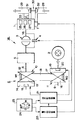
つぎに、この発明の実施例を図面に基づいて説明する。まず、この発明を適用できる車両のパワートレーン、およびその車両の制御系統を、図4に示す。図4に示す車両Veにおいては、動力源1と車輪2との間の動力伝達経路に、流体伝動装置3、ロックアップクラッチ4、前後進切り換え機構5、無段変速機6などが設けられている。動力源1としては、例えば、内燃機関または電動機の少なくとも一方を用いることができ、好ましくは電子スロットルバルブ7を備えた内燃機関などの出力を電気的に制御できる機構を備えた内燃機関が使用される。電動機としては、電気エネルギを運動エネルギに変換する力行機能と、運動エネルギを電気エネルギに変換する回生機能とを有するモータ・ジェネレータを用いることが可能である。この実施例では、動力源1として、電子スロットルバルブ7を備えたガソリンエンジンやディーゼルエンジンあるいは天然ガスエンジンなどの内燃機関が用いられている場合について説明する。
Next, an embodiment of the present invention will be described with reference to the drawings. First, a power train of a vehicle to which the present invention can be applied and a control system of the vehicle are shown in FIG. In the vehicle Ve shown in FIG. 4, a fluid transmission device 3, a
この動力源1は、シリンダ(図示せず)およびピストン(図示せず)により形成された燃焼室(図示せず)を有しており、燃料を燃焼させることにより生じた熱エネルギを運動エネルギに変換して出力する原動機である。このために、動力源1は、燃料噴射量制御装置25と、点火時期制御装置26と、吸気バルブおよび排気バルブの開閉タイミングおよび開閉量を制御するバルブ制御装置27とを有している。さらに、動力源1の燃焼室に連通する吸気管28および排気管29が設けられている。この吸気管28に前記電子スロットルバルブ7が設けられており、電子スロットルバルブ7により吸入空気量が制御される。
The power source 1 has a combustion chamber (not shown) formed by a cylinder (not shown) and a piston (not shown), and heat energy generated by burning the fuel is converted into kinetic energy. It is a prime mover that converts and outputs. For this purpose, the power source 1 includes a fuel injection amount control device 25, an ignition timing control device 26, and a valve control device 27 that controls the opening / closing timing and the opening / closing amount of the intake and exhaust valves. Further, an
また、吸気管28を経由してシリンダ内に圧縮空気を供給するための過給器30が設けられている。この過給器30としては、機械駆動方式の過給器または排気タービン方式の過給器のいずれを用いてもよい。機械駆動方式の過給器とは、動力源1のクランクシャフト1Aの動力により駆動されて、圧縮空気を供給する構造のものである。また、排気タービン方式の過給器とは、排気管29の排気ガスの運動エネルギにより駆動されて、圧縮空気を供給する構造のものである。この実施例では、過給器30として、排気タービン方式が用いられている場合を説明する。
Further, a
この排気タービン方式の過給器30は、排気管29に設けられたタービン31と、このタービン31と一体回転するように連結され、かつ、吸気管28に設けられたコンプレッサ32とを有している。このコンプレッサ32は、吸気管28内であって、電子スロットルバルブ7よりも上流に配置されている。また、過給器30によりシリンダに供給される圧縮空気の圧力、つまり、過給圧を制御する過給圧制御装置33が設けられている。過給圧制御装置33としては、例えば、ウェイストゲートバルブを用いることが可能である。このウェイストゲートバルブは、燃焼室から排気管29に排出される排気ガスの一部を、タービン31をバイパスさせて排気管29の外部に排出させる装置である。そして、ウェイストゲートバルブの開度を調整することにより、排気ガスの流動によってタービン31に与えられる運動エネルギを制御して、過給圧を制御することが可能となっている。
The
また、流体伝動装置3およびロックアップクラッチ4は、動力源1と前後進切り換え機構5との間の動力伝達経路に設けられており、流体伝動装置3とロックアップクラッチ4とは相互に並列に配置されている。流体伝動装置3は、流体の運動エネルギにより動力を伝達する装置であり、具体的には流体式トルクコンバータであり、ロックアップクラッチ4は、摩擦力により動力を伝達する装置であって、トルクコンバータのポンプインペラなどの入力側の部材とタービンランナなどの出力側の部材とを直接連結するように構成されている。前後進切り換え機構5は、入力されたトルクを選択的に反転して出力する装置であって、例えば遊星歯車機構を主体として構成されている。
Further, the fluid transmission device 3 and the
無段変速機6は、要は、変速比を連続的に変化させることのできる機構であって、ベルト式あるいはトロイダル型の無段変速機を使用することができる。図4にはベルト式のものが示されており、この無段変速機6は、前後進切り換え機構5と車輪2との間の動力伝達経路に設けられている。無段変速機6についてより具体的に説明すると、相互に平行に配置されたプライマリシャフト8およびセカンダリシャフト9が設けられている。このプライマリシャフト8にはプライマリプーリ10が設けられており、セカンダリシャフト9にはセカンダリプーリ11が設けられている。プライマリプーリ10は、プライマリシャフト8に固定された固定シーブ12と、プライマリシャフト8の軸線方向に移動できるように構成された可動シーブ13とを有している。そして、固定シーブ12と可動シーブ13との間にV字形状の溝M1が形成されている。
The continuously variable transmission 6 is basically a mechanism capable of continuously changing the gear ratio, and a belt-type or toroidal-type continuously variable transmission can be used. FIG. 4 shows a belt type, and the continuously variable transmission 6 is provided in a power transmission path between the forward / reverse switching mechanism 5 and the wheels 2. More specifically, the continuously variable transmission 6 is provided with a primary shaft 8 and a
また、この可動シーブ13をプライマリシャフト8の軸線方向に動作させることにより、可動シーブ13と固定シーブ12とを接近・離隔させる油圧サーボ機構14が設けられている。この油圧サーボ機構14は、油圧室15と、油圧室15のオイル量または油圧に応じてプライマリシャフト8の軸線方向に動作しかつ可動シーブ13に接続されたピストン(図示せず)とを備えている。
In addition, a hydraulic servo mechanism 14 is provided that moves the movable sheave 13 in the axial direction of the primary shaft 8 to bring the movable sheave 13 and the fixed sheave 12 closer to or away from each other. The hydraulic servo mechanism 14 includes a
一方、セカンダリプーリ11は、セカンダリシャフト9に固定された固定シーブ16と、セカンダリシャフト9の軸線方向に移動できるように構成された可動シーブ17とを有している。そして、固定シーブ16と可動シーブ17との間にはV字形状の溝M2が形成されている。そして、これらの溝M1,M2に挟持された状態でベルト18が各プーリ10,11に巻き掛けられている。
On the other hand, the secondary pulley 11 has a fixed
また、この可動シーブ17をセカンダリシャフト9の軸線方向に動作させることにより、可動シーブ17と固定シーブ16とを接近・離隔させる油圧サーボ機構19が設けられている。この油圧サーボ機構19は、油圧室20と、油圧室20の油圧またはオイル量に応じてセカンダリシャフト9の軸線方向に動作しかつ可動シーブ17に接続されたピストン(図示せず)とを備えている。
Further, a
一方、無段変速機6の油圧サーボ機構14,19およびロックアップクラッチ4、および前後進切り換え機構5を制御する機能を有する油圧制御装置21が設けられている。さらに、動力源1、ロックアップクラッチ4、前後進切り換え機構5、無段変速機6、油圧制御装置21を制御するコントローラとしての電子制御装置22が設けられており、この電子制御装置22は、演算処理装置(CPUまたはMPU)および記憶装置(RAMおよびROM)ならびに入出力インターフェースを主体とするマイクロコンピュータにより構成されている。前記油圧制御装置21は、ソレノイドバルブおよび油圧回路を有しているとともに、ソレノイドバルブのデューティ値を制御することにより、油圧室15,20に供給されるオイル量、および油圧室15,20から排出されるオイル量が制御される構成となっている。
On the other hand, a hydraulic control device 21 having a function of controlling the
図4に示す無段変速機6の変速比を車両Veの走行状態、すなわちアクセル開度や車速などに基づいて制御する自動変速制御と、手動操作に基づいて変速を実行する手動変速(マニュアルシフト)制御とを実行できるように構成されている。シフト装置23は、その自動変速制御と手動変速制御とを選択するように構成されている。その一例を説明すると、シフトレバー24をガイドするガイド溝が図4に模式的に示すように変形したH字形に形成され、一方の直線部分にパーキングポジション(P)、リバースポジション、ニュートラルポジション、ドライブポジション(D)、ブレーキポジション(B)が割り付けられ、かつドライブポジションから分岐した他方の直線部分の中央部がマニュアルポジション(M)に割り付けられ、このマニュアルポジションを挟んでアップシフトポジション(+)とダウンシフトポジション(−)とが設けられている。そして、各ポジションを検出するスイッチなどのセンサ(図示せず)が設けられており、そのセンサの出力信号が前記電子制御装置22に入力されている。また、シフトレバーの移動を前記油圧制御装置21に伝達するためのケーブルなどのリンゲージ(図示せず)が設けられている。
The automatic transmission control for controlling the gear ratio of the continuously variable transmission 6 shown in FIG. 4 based on the running state of the vehicle Ve, that is, the accelerator opening, the vehicle speed, and the like, and the manual transmission for performing the gear shifting based on the manual operation ) Control and can be executed. The
上記の電子制御装置22に入力される信号を例示すると、エンジン回転数、アクセルペダルの操作状態、ブレーキペダルの操作状態、スロットルバルブ7の開度、プライマリシャフト8の回転数、セカンダリシャフト9の回転数、油圧制御装置21のソレノイドバルブのフェールの有無、エンジン1の吸入空気量、登坂路か否かなどを検知するセンサの信号、シフト装置23で選択されているシフトポジションを示す信号、前記アップシフトポジションに設けられたセンサからのアップシフト信号、前記ダウンシフトポジションに設けられているセンサからのダウンシフト信号、過給圧を検知するセンサの信号などである。また、電子制御装置22には各種のデータが記憶されており、電子制御装置22に入力される信号、および記憶されているデータに基づいて、電子制御装置22から、動力源1を制御する信号、無段変速機6を制御する信号、前後進切り換え機構5を制御する信号、ロックアップクラッチ4を制御する信号、油圧制御装置21を制御する信号などが出力される。
Examples of signals input to the
電子制御装置22に記憶されているデータとしては、エンジントルク制御マップ、変速機制御マップ、ロックアップクラッチ制御マップなどが挙げられる。エンジントルク制御マップは、例えば電子スロットルバルブ7の制御量の一時的な増大量を設定したマップである。また、変速機制御マップには、変速比の制御マップ、トルク容量の制御マップなどが含まれる。変速比制御マップは、車速、アクセル開度、減速度もしくはブレーキの操作状態などに基づいて、無段変速機6の変速比もしくは動力源1の目標回転数を設定するマップである。動力源1としてエンジンが用いられている場合は、無段変速機6の変速比の制御により、エンジン回転数を最適燃費曲線に近づけるように制御できる。なお、この回転数制御は、主として目標回転数と実回転数との偏差に基づくフィードバック制御によっておこなわれ、必要に応じてフィードフォワード制御が実行もしくは併用される。トルク容量制御マップは、変速比、伝達するべきトルクなどに基づいて、無段変速機6のトルク容量を制御する場合に用いるマップである。また、ロックアップクラッチ制御マップは、車速、アクセル開度などに基づいて、ロックアップクラッチ4のトルク容量を設定するマップである。
The data stored in the
上述したように、無段変速機6は動力源1の回転数を燃費が最適になる回転数に制御するように機能させることができる。このいわゆる通常の制御では、一例として、アクセル開度などで代表される駆動要求量と車速とに基づいて適宜のマップから要求駆動力を求め、その要求駆動力と車速とから動力源の目標出力を算出する。その目標出力を最適燃費で出力することのできる目標回転数をいわゆる最適燃費線と目標出力線との交点での回転数としてマップなどから求め、その目標回転数と実際の動力源回転数との差を制御偏差して無段変速機6の変速比がフィードバック制御される。一方、目標出力とその時点の車速などに基づいて目標トルクが算出され、その目標トルクを達成するように電子スロットルバルブ7などによって動力源1の出力トルクが制御される。 As described above, the continuously variable transmission 6 can function so as to control the rotational speed of the power source 1 to the rotational speed at which the fuel efficiency is optimized. In this so-called normal control, for example, the required driving force is obtained from an appropriate map based on the required driving amount represented by the accelerator opening and the vehicle speed, and the target output of the power source is calculated from the required driving force and the vehicle speed. Is calculated. The target rotational speed at which the target output can be output with the optimum fuel efficiency is obtained from a map etc. as the rotational speed at the intersection of the so-called optimal fuel efficiency line and the target output line, and the target rotational speed and the actual power source rotational speed The gear ratio of the continuously variable transmission 6 is feedback controlled by controlling the difference. On the other hand, a target torque is calculated based on the target output and the vehicle speed at that time, and the output torque of the power source 1 is controlled by the electronic throttle valve 7 or the like so as to achieve the target torque.
このいわゆる通常制御は、車速や流体伝動装置3のタービン回転数などとアクセル開度などの要求駆動量とで定まる走行状態に基づいて無段変速機6を制御するものであるが、無段変速機6の変速比の制御としては、手動操作に基づく制御も可能である。その制御は、シフト装置23のアップシフトポジションあるいはダウンシフトポジションに設けられているスイッチもしくはセンサを、シフトレバーによってオン動作させて信号を出力させ、その信号に基づいて、動力源1の目標回転数をステップ的に変化させ、あるいは信号の出力している間、目標回転数を連続的に変化させる制御である。このような変速制御が、手動変速制御(マニュアルシフト制御)である。
In this so-called normal control, the continuously variable transmission 6 is controlled based on the traveling state determined by the vehicle speed, the turbine rotational speed of the fluid transmission device 3 and the required driving amount such as the accelerator opening. As control of the gear ratio of the machine 6, control based on manual operation is also possible. The control is such that a switch or sensor provided in the upshift position or downshift position of the
手動変速操作は、車両の機敏な動作を期待して実行するから、変速速度(変速比変化率)が大きくなるように無段変速機6が制御される。例えば、減速時にマニュアルダウンシフト操作した場合には、変速比を通常より速い速度で増大させる。また反対に加速中にマニュアルアップシフト操作した場合には、通常より速い速度で変速比を減少させる。 Since the manual speed change operation is executed in anticipation of an agile operation of the vehicle, the continuously variable transmission 6 is controlled so that the speed change speed (speed change ratio) is increased. For example, when a manual downshift operation is performed during deceleration, the gear ratio is increased at a speed faster than usual. Conversely, when a manual upshift is performed during acceleration, the gear ratio is reduced at a speed higher than usual.
また、このようなマニュアルシフトの場合、変速速度が速いので、ショックを緩和もしくは防止するために、エンジントルクの制御が併せて実行される。具体的には、減速時のマニュアルダウンシフトの場合には、エンジントルクを迅速に増大させる制御が実行される。これは、図4に示す車両では、電子スロットルバルブ7の開度を増大させ、その後、徐々に復帰させる制御である。このエンジントルク制御が変速制御と協調して実行されると、変速比の増大に伴ういわゆるエンジンブレーキ力を、エンジントルクの制御によって小さくし、変速比が急激に増大することによる駆動トルクの変化を抑制してショックが防止もしくは緩和される。また、マニュアルアップシフトの場合、変速比が急激に小さくなることによって動力源1やこれに関連する回転部材の回転数が減少して慣性トルクが発生し、これがショックの原因となるので、その慣性トルクを相殺するようにエンジントルクが低下させられる。このようにエンジントルクの制御も、通常のマニュアルシフト制御に含まれる。 In the case of such a manual shift, since the shift speed is high, engine torque control is also executed in order to reduce or prevent a shock. Specifically, in the case of a manual downshift at the time of deceleration, control for rapidly increasing the engine torque is executed. This is a control in which the opening degree of the electronic throttle valve 7 is increased and then gradually returned in the vehicle shown in FIG. When this engine torque control is executed in cooperation with the speed change control, the so-called engine braking force accompanying the increase in the speed change ratio is reduced by the engine torque control, and the change in the drive torque due to the speed change increasing rapidly. Suppress and prevent or alleviate shock. Further, in the case of manual upshifting, the gear ratio is rapidly reduced, so that the rotational speed of the power source 1 and the rotating member related thereto is reduced and inertia torque is generated, which causes a shock. The engine torque is reduced so as to cancel the torque. Thus, the engine torque control is also included in the normal manual shift control.
上記のマニュアルシフト制御とそれに伴うエンジントルク制御とがタイミングのズレを生じることなく協調して実行されると、それぞれの制御による駆動トルクの変動要因が相互に作用してショックが防止もしくは抑制される。しかしながら、無段変速機6での変速制御は、前述したプライマリプーリ11側の油圧室15に圧油を給排することにより実行されるのに対して、動力源(エンジン)1の出力トルクは、燃料の供給量や吸入空気量の変化の後、その混合気の燃焼の変化が生じた後に変化し、それぞれの変化が相対的に緩慢であることと相俟って、エンジントルクの変化が、変速比の変化に対して遅延する場合がある。すなわち、変速比の変化に対してエンジントルクの変化が相対的に遅延する場合がある。このような場合には、変速比の変化に起因する駆動トルクの変化を、エンジントルクの変化によって抑制することができなくなるので、ショックが悪化する。そこでこの発明の制御装置は、以下の制御を実行するように構成されている。
When the above-mentioned manual shift control and the accompanying engine torque control are executed in a coordinated manner without causing a timing shift, the fluctuation factors of the drive torque due to the respective controls interact to prevent or suppress the shock. . However, the shift control in the continuously variable transmission 6 is executed by supplying and discharging the pressure oil to the
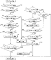
図1はその制御の一例を説明するためのフローチャートであって、このフローチャートで示されるルーチンは、所定の短時間毎に繰り返し実行される。図1において、先ず、マニュアルダウン操作時か否かが判断される(ステップS1)。これは、前述したシフト装置23におけるアップシフトポジションもしくはダウンシフトポジションのセンサが信号を出力したか否かによって判断することができる。このステップS1で肯定的に判断された場合には、電子スロットルバルブ(電スロ)7の制御が許可されているか否かが判断される(ステップS2)。エンジンの暖機が終了していない場合や排気浄化触媒の温度が高くなっている場合などでは電子スロットルバルブ7の制御が禁止される。ステップS2ではこのようないわゆる禁止条件が成立しているか否かが判断される。
FIG. 1 is a flowchart for explaining an example of the control. The routine shown in this flowchart is repeatedly executed every predetermined short time. In FIG. 1, it is first determined whether or not a manual down operation is being performed (step S1). This can be determined based on whether or not the sensor of the upshift position or downshift position in the
ステップS2で否定的に判断された場合には、特に制御をおこなうことなくこのルーチンを一旦終了する。これに対してステップS2で肯定的に判断された場合には、変速に比べて電子スロットルバルブ7の応答性が遅い領域(遅い状態)か否かが判断される(ステップS3)。この応答性は、電子スロットルバルブ7自体の応答性だけではなく、要は、エンジントルクの制御指令の出力に対する実際のエンジントルクの変化の応答性である。その応答性は、例えば現在時点のスロットル開度やエンジン回転数などに基づいて判断することができる。 If a negative determination is made in step S2, this routine is temporarily terminated without performing any particular control. On the other hand, if an affirmative determination is made in step S2, it is determined whether or not the electronic throttle valve 7 is in a region where the response of the electronic throttle valve 7 is slow (slow state) compared to the shift (step S3). This responsiveness is not only the responsiveness of the electronic throttle valve 7 itself, but is also the responsiveness of the actual engine torque change to the output of the engine torque control command. The responsiveness can be determined based on, for example, the throttle opening degree and the engine speed at the current time point.
変速に比べて電子スロットルバルブ7の応答性が遅いことがステップS3で判断された場合、すなわちステップS3で肯定的に判断された場合には、電子スロットルバルブ7に対する指令値を一時的に増大させる制御の実行条件が成立しているか否かが判断される。具体的には、先ず、マニュアルダウンシフトが多重変速か否か、あるいはスロットル開度を増大させる前回の要求の終了から所定期間内か否かが判断される(ステップS4)。多重変速とは、所定の変速比(もしくは入力回転数)を目標とした変速制御中に他の変速比(もしくは入力回転数)を目標とする変速が生じる変速状態である。このような状態では、変速比の変化が重畳的に生じ、それぞれに応じて電子スロットルバルブ7に対する指令値を一時的に増大させる制御を実行すると、制御が錯綜して安定した制御ができない可能性がある。また、スロットル開度を増大させる前回の要求の終了から所定期間内では、エンジントルクが安定していない場合があり、その影響でエンジントルクを所期どおりに制御できない可能性がある。そのために、多重変速でないこと、スロットル開度を増大させる前回の要求の終了から所定期間内でないことを実行条件としたのである。 If it is determined in step S3 that the response of the electronic throttle valve 7 is slower than the speed change, that is, if it is determined positive in step S3, the command value for the electronic throttle valve 7 is temporarily increased. It is determined whether or not a control execution condition is satisfied. Specifically, first, it is determined whether or not the manual downshift is a multiple shift, or whether or not it is within a predetermined period from the end of the previous request for increasing the throttle opening (step S4). The multiple shift is a shift state in which a shift targeting another gear ratio (or input rotation speed) occurs during shift control targeting a predetermined gear ratio (or input rotation speed). In such a state, a change in the gear ratio occurs in a superimposed manner, and if control for temporarily increasing the command value for the electronic throttle valve 7 is executed in accordance with each change, there is a possibility that control is complicated and stable control cannot be performed. There is. In addition, the engine torque may not be stable within a predetermined period from the end of the previous request to increase the throttle opening, and the engine torque may not be controlled as expected due to the influence. For this reason, the execution condition is that it is not a multiple shift and that it is not within a predetermined period from the end of the previous request to increase the throttle opening.
また、急減速中か否かが判断される(ステップS5)。これは、例えば車輪の回転数や出力軸の回転数の変化率に基づいて判断することができる。急減速状態となっていれば、マニュアルダウンシフト操作によって達成するべき減速状態が生じているので、それ以上に駆動トルクを低下させる必要がない。したがって急減速中でないことを実行条件としたのである。 Further, it is determined whether or not sudden deceleration is in progress (step S5). This can be determined based on, for example, the rate of change of the rotational speed of the wheel or the rotational speed of the output shaft. If it is in the sudden deceleration state, the deceleration state to be achieved by the manual downshift operation has occurred, so there is no need to further reduce the drive torque. Therefore, the execution condition is that the vehicle is not suddenly decelerating.
したがってステップS4あるいはステップS5で肯定的に判断された場合には、特に制御をおこなうことなくこのルーチンを一旦終了する。これとは反対にステップS4およびステップS5で否定的に判断された場合には、ファーストオープンを実施する(ステップS6)。 Therefore, when a positive determination is made at step S4 or step S5, this routine is temporarily terminated without performing any particular control. On the contrary, if a negative determination is made in step S4 and step S5, a first open is performed (step S6).
マニュアルダウンシフトは、シフト装置23が手動操作されることにより変速比を急速に増大させる変速制御であり、その場合、動力源1の出力トルクが変化しないと、変速比の増大による制動トルクが急激に増大し、これがショックの要因となるので、マニュアルダウンシフトの開始時に動力源1の出力トルクを増大させ、その後に動力源1の出力トルクを元のトルクに戻す制御が実行される。その制御による動力源1の出力トルクの増大が変速に対して遅延することが上記のステップS3で判断されているので、その遅延を解消もしくは抑制する制御が実行される。これがファーストオープン制御である。
The manual downshift is a shift control in which the gear ratio is rapidly increased by manually operating the
具体的には、制御開始当初の動力源1の出力トルクの変化指令値(すなわち電子スロットルバルブ7に対する開度増大指令値)を、通常のマニュアルダウンシフト時における値より、一時的に増大させる。その増大量や増大の継続時間などは、予め定めた一定値であってもよく、あるいは車両の走行状態もしくは前記遅延の状態に応じて求めたものであってもよい。電子スロットルバルブ7に対する指令値が一時的に増大させられることにより、エンジンに対する吸入空気量や燃料の供給量が、通常より一時的に増大させられ、その結果、動力源1の出力トルクの増大が通常より速くなり、変速に対する動力源1の出力トルクの増大の遅延が解消もしくは緩和される。 Specifically, the change command value of the output torque of the power source 1 at the beginning of the control (that is, the opening increase command value for the electronic throttle valve 7) is temporarily increased from the value at the time of normal manual downshift. The amount of increase and the duration of the increase may be a predetermined constant value, or may be obtained according to the running state of the vehicle or the delay state. By temporarily increasing the command value for the electronic throttle valve 7, the amount of intake air and the amount of fuel supplied to the engine are temporarily increased from normal, and as a result, the output torque of the power source 1 is increased. It becomes faster than usual, and the delay in increasing the output torque of the power source 1 with respect to the shift is eliminated or alleviated.
ついで、上記のファーストオープン制御を実行しても変速に対する動力源1の出力トルクの変化の遅延が解消されないか否か(すなわち、間に合わないか否か)が判断される(ステップS7)。このステップS7で否定的に判断された場合には、一旦、このルーチンを終了する。これとは反対にステップS7で肯定的に判断された場合には、手動操作に伴う変速の開始を遅延させる変速開始ディレイ制御が実行される(ステップS8)。これは、無段変速機6に対する変速指令信号の出力を時間的に遅らせることによって実行される。その遅れ時間は一定値であってもよく、マニュアルダウンシフトの内容に応じて変化する時間であってもよい。 Next, it is determined whether or not the delay of the change in the output torque of the power source 1 with respect to the shift is not eliminated even if the above-described fast open control is executed (that is, whether or not it is not in time) (step S7). If a negative determination is made in step S7, this routine is once terminated. On the other hand, if the determination in step S7 is affirmative, shift start delay control is executed to delay the start of shift associated with manual operation (step S8). This is executed by delaying the output of the shift command signal to the continuously variable transmission 6 in terms of time. The delay time may be a constant value, or may be a time that varies depending on the content of the manual downshift.
マニュアルダウン操作がおこなわれることにより上記の各判断や制御が開始されると、上記のステップS1で否定的に判断される。その場合は、マニュアルダウン変速開始ディレイ中か否か、すなわち上記のステップS8での制御の実行中か否かが判断される(ステップS9)。前述したファーストオープンによってエンジントルクの変化の相対的な遅延が解消される場合には、変速開始ディレイ制御が実行されていないので、このステップS9で否定的に判断される。その場合には、マニュアルダウン変速中か否かが判断される(ステップS10)。既にマニュアルダウン変速が終了していれば、このステップS10で否定的に判断され、その場合は直ちにこのルーチンを終了する。これに対して、マニュアルダウン変速の制御が継続していれば、ステップS10で肯定的に判断される。その場合、上記のファーストオープン制御の実施中か否かが判断される(ステップS11)。 When each of the above determinations and controls is started by performing a manual down operation, a negative determination is made in step S1. In this case, it is determined whether or not a manual downshift start delay is in progress, that is, whether or not the control in step S8 is being executed (step S9). When the relative delay of the change in the engine torque is eliminated by the first opening described above, the shift start delay control is not executed, so a negative determination is made in this step S9. In that case, it is determined whether or not a manual downshift is being performed (step S10). If the manual downshift has already been completed, a negative determination is made in step S10, and in this case, this routine is immediately terminated. On the other hand, if the manual downshift control is continued, an affirmative determination is made in step S10. In this case, it is determined whether or not the first open control is being performed (step S11).
前述したようにファーストオープン制御は所定時間の間を「一時的」として実行されるから、その所定時間が経過していない状態すなわち制御開始直後では、このステップS11で肯定的に判断され、その場合は、ファーストオープン制御の開始から所定時間が経過したか否かが判断される(ステップS12)。その所定時間が経過していないことによりステップS12で否定的に判断された場合には、ファーストオープン制御を継続する(ステップS13)。その後、一旦、このルーチンを終了する。 As described above, since the first open control is executed as “temporary” for a predetermined time, in a state where the predetermined time has not elapsed, that is, immediately after the start of the control, an affirmative determination is made in this step S11. It is determined whether or not a predetermined time has elapsed since the start of the first open control (step S12). If it is determined negative in step S12 because the predetermined time has not elapsed, the fast open control is continued (step S13). Thereafter, this routine is terminated once.
こうしてファーストオープン制御が所定時間継続して実行されると、ステップS12で肯定的に判断され、その場合は、ファーストオープン制御を終了して通常のトルクアップ要求制御が実施される(ステップS14)。すなわち、マニュアルダウンシフトに伴って通常実施される動力源1の出力トルクの増大制御に移行する。具体的には、電子スロットルバルブ7の開度を通常制御以上に増大させる指令信号の出力を中止し、通常のトルクアップ制御指令信号を出力する。この時点では、変速比の増大と協調して動力源1の出力トルクが増大しているので、電子スロットルバルブ7に対する指令信号を通常のマニュアルダウンシフト時の信号に戻しても、エンジンブレーキ力が過大になってショックが生じるなどの事態が回避もしくは抑制される。 When the first open control is continuously executed for a predetermined time in this manner, an affirmative determination is made in step S12. In this case, the first open control is terminated and normal torque-up request control is performed (step S14). That is, the control shifts to the increase control of the output torque of the power source 1 that is normally performed with the manual downshift. Specifically, the output of the command signal for increasing the opening degree of the electronic throttle valve 7 beyond the normal control is stopped, and the normal torque up control command signal is output. At this time, the output torque of the power source 1 is increased in cooperation with the increase in the gear ratio, so that the engine braking force is maintained even if the command signal for the electronic throttle valve 7 is returned to the signal at the time of normal manual downshift. A situation such as a shock due to an excessive amount is avoided or suppressed.
一方、マニュアルダウン変速開始ディレイ制御が実行されていてステップS9で肯定的に判断された場合には、そのディレイ制御の開始から所定時間が経過したか否かが判断される(ステップS15)。この所定時間は、マニュアルダウンシフト変速開始ディレイ制御の継続時間として予め設定されている時間である。制御開始当初は、時間が経過していないので、このステップS15で否定的に判断され、その場合は、前述したステップS11に進み、ファーストオープン制御が継続される。これに対して、時間が経過したことによってステップS15で肯定的に判断された場合には、動力源1の出力トルク制御の遅延に応じた時間が経過したことになるので、上記のディレイ制御が終了させられる(ステップS16)。 On the other hand, if manual downshift start delay control is being executed and a positive determination is made in step S9, it is determined whether or not a predetermined time has elapsed since the start of the delay control (step S15). This predetermined time is a time set in advance as a duration of manual downshift start-of-shift delay control. At the beginning of the control, since time has not elapsed, a negative determination is made in step S15. In this case, the process proceeds to step S11 described above, and the fast open control is continued. On the other hand, if it is determined affirmative in step S15 because the time has elapsed, the time corresponding to the delay in the output torque control of the power source 1 has elapsed. The process is terminated (step S16).
ついで、ステップS11に進み、前述したファーストオープン制御およびその後の通常のトルクアップ要求に基づく制御が実行される。したがって、ファーストオープン制御によって動力源1の出力トルクの増大がマニュアルダウンシフトに間に合わない場合には、変速自体が遅延させられるので、動力源1の出力トルクの変化と変速との時間的なズレが解消もしくは抑制され、その結果、変速比が増大した時点では動力源1の出力トルクが増大していて駆動トルクの変化すなわちショックが防止もしくは緩和される。 Next, the process proceeds to step S11, and the above-described first open control and control based on the subsequent normal torque increase request are executed. Accordingly, when the increase in the output torque of the power source 1 is not in time for the manual downshift due to the fast open control, the shift itself is delayed, and therefore, there is a temporal deviation between the change in the output torque of the power source 1 and the shift. As a result, when the gear ratio is increased, the output torque of the power source 1 is increased and the change of the drive torque, that is, the shock is prevented or alleviated.
なお、上述したステップS3で否定的に判断された場合、すなわち動力源1のトルクの変化が変速に対して遅れない場合には、ステップS14に進んで通常のトルクアップ制御が実施される。 If a negative determination is made in step S3 described above, that is, if the change in the torque of the power source 1 is not delayed with respect to the shift, the routine proceeds to step S14 where normal torque-up control is performed.
手動変速が可能な状態すなわちマニュアルレンジでは、変速が手動操作に基づいて実行されるから、手動操作されない状態では、変速比が従前のまま維持される。したがってマニュアルレンジでアクセルペダル(図示せず)を踏み込んで加速し、その結果、動力源1の回転数が増大した場合、手動でアップシフト操作をおこない、変速比および動力源1の回転数を低下させることになる。その場合においても、いわゆるマニュアルアップシフトであるから、運転者の要求を満たすように変速速度がいわゆる自動変速の場合に比較して速くなり、それに伴う回転数変化で慣性トルクが生じる。 In a state where manual shifting is possible, that is, in manual range, shifting is executed based on manual operation. Therefore, in a state where manual operation is not performed, the gear ratio is maintained as before. Therefore, when an accelerator pedal (not shown) is depressed in the manual range and accelerated, as a result, when the rotational speed of the power source 1 increases, an upshift operation is manually performed to reduce the gear ratio and the rotational speed of the power source 1. I will let you. Even in such a case, since it is a so-called manual upshift, the shift speed becomes faster than the so-called automatic shift so as to satisfy the driver's request, and an inertia torque is generated by a change in the rotational speed.
その慣性トルクに起因するショックを防止するために、通常のマニュアルアップシフト制御では、動力源1の出力トルクが、過渡的に、低下させられる。そのマニュアルアップシフトの際の変速速度が車両の状態などに応じて速くなった場合、動力源1の出力トルクの変化が相対的に遅延することがあり、そこでこの発明の制御装置では、マニュアルアップシフトの場合にも、動力源1のトルクの変化指令値を一時的に増大させるいわゆる特別制御が、マニュアルダウンシフトの場合と同様に実行される。 In order to prevent a shock caused by the inertia torque, in the normal manual upshift control, the output torque of the power source 1 is transiently reduced. When the gear shifting speed during the manual upshift increases according to the state of the vehicle, the change in the output torque of the power source 1 may be relatively delayed. Also in the case of a shift, so-called special control that temporarily increases the torque change command value of the power source 1 is executed as in the case of a manual downshift.
図2はその制御例を説明するためのフローチャートであって、先ず、マニュアルアップ操作時か否かが判断される(ステップS21)。これは、前述した図1のステップS1での判断と同様に、前述したシフト装置23から出力される信号に基づいて判断することができる。このステップS21で否定的に判断された場合には、特に制御をおこなうことなくこのルーチンを一旦終了する。これに対してステップS21で肯定的に判断された場合には、電子スロットルバルブ7を制御できる条件が成立しているか否かが判断される(ステップS22)。これは、前述した図1におけるステップS2の判断と同様にしておこなうことができる。
FIG. 2 is a flowchart for explaining the control example. First, it is determined whether or not the manual up operation is being performed (step S21). This can be determined based on the signal output from the
ステップS22で否定的に判断された場合には、特に制御をおこなうことなくこのルーチンを一旦終了する。これに対してステップS22で肯定的に判断された場合には、通常の電子スロットルバルブ7の閉じ制御が実施される(ステップS23)。すなわち、マニュアルアップシフトの際に変速比の低下に伴う動力源1などの回転数の低下に伴う慣性トルクを相殺するように、動力源1の出力トルクを低下させる制御が、このステップS23での制御であり、したがってその電子スロットルバルブ7の閉じ制御によるスロットル開度の減少量は、一定値として予め定められ、あるいは変速速度やエンジン回転数などによって予め定められている。 If a negative determination is made in step S22, this routine is temporarily terminated without performing any particular control. On the other hand, when a positive determination is made in step S22, normal control for closing the electronic throttle valve 7 is performed (step S23). That is, the control for reducing the output torque of the power source 1 so as to cancel out the inertia torque accompanying the decrease in the rotational speed of the power source 1 or the like accompanying the decrease in the gear ratio during the manual upshift is performed in this step S23. Therefore, the amount of decrease in the throttle opening due to the closing control of the electronic throttle valve 7 is determined as a constant value, or is determined in advance by a shift speed, an engine speed, or the like.
ついで、変速に対する動力源1のトルクの変化の遅延が判断される(ステップS24)。具体的には、変速に比べて電子スロットルバルブ7の応答性が遅い領域(遅延する状態)か否かが判断される。これは、前述した図1に示すステップS3での判断と同様にしておこなうことができる。このステップS24で否定的に判断された場合には、通常のマニュアルアップシフト制御を実行すればよいから、図2に示すルーチンでは特に制御をおこなうことなく、一旦、終了する。 Next, a delay in changing the torque of the power source 1 with respect to the shift is determined (step S24). Specifically, it is determined whether or not the electronic throttle valve 7 is in a region where the response of the electronic throttle valve 7 is slow (delayed state) as compared with the shift. This can be performed in the same manner as the determination in step S3 shown in FIG. If a negative determination is made in step S24, normal manual upshift control may be executed. Therefore, the routine shown in FIG. 2 ends once without performing any particular control.
これに対してステップS24で肯定的に判断された場合には、動力源1のトルクを変化させる指令値を一時的に増大させる制御を実行する条件の成立が判断される(ステップS25)。これは、前述した図1におけるステップS4と同様の判断であり、マニュアルアップシフトが多重変速か否か、あるいはスロットル開度の前回の閉じ要求の終了から所定期間内か否かが判断される。このステップS25で肯定的に判断された場合には、実行条件が成立していないことになるので、特に制御をおこなうことなくこのルーチンを一旦終了する。すなわち通常の電子スロットルバルブ7の閉じ制御が実行される。 On the other hand, when a positive determination is made in step S24, it is determined that a condition for executing a control for temporarily increasing the command value for changing the torque of the power source 1 is satisfied (step S25). This is the same determination as in step S4 in FIG. 1 described above, and it is determined whether or not the manual upshift is a multiple shift or whether or not it is within a predetermined period from the end of the previous closing request of the throttle opening. If the determination in step S25 is affirmative, the execution condition is not satisfied, so this routine is temporarily terminated without performing any particular control. That is, normal closing control of the electronic throttle valve 7 is executed.
これとは反対にステップS25で否定的に判断された場合には、実行条件が成立していることになるので、ファーストクローズ制御が実施される(ステップS26)。これは、前述したファーストオープン制御とは反対の制御であって、動力源1の出力トルクを迅速に低下させるために、電子スロットルバルブ7を閉じるための指令値を一時的に増大(閉じ方向に増大)させる制御である。すなわち指令値を大きくすることにより、電子スロットルバルブ7を迅速に動作させ、動力源1のトルクの低下を速める制御である。なお、その指令値の増大量やその継続時間は、予め定めた一定値であってもよく、あるいは動力源1の出力トルクの遅れの程度や車両の走行状態に基づいて定められる値であってもよい。 On the other hand, if a negative determination is made in step S25, the execution condition is satisfied, and the fast close control is performed (step S26). This is a control opposite to the aforementioned fast open control, and in order to quickly reduce the output torque of the power source 1, the command value for closing the electronic throttle valve 7 is temporarily increased (in the closing direction). Control). That is, by increasing the command value, the electronic throttle valve 7 is operated quickly, and the torque of the power source 1 is quickly reduced. The increase amount of the command value and the duration thereof may be a predetermined constant value, or a value determined based on the degree of delay of the output torque of the power source 1 and the running state of the vehicle. Also good.
図3は、上記の図2に示す制御を実施した場合と実施しない場合とを比較して示す模式的なタイムチャートである。マニュアルアップシフト制御の開始に伴ってスロットル開度を閉じる方向の指令値が出力される。通常の制御では、図3に破線で示す指令値となるが、電子スロットルバルブ7の応答性の遅れが判断されている場合には、上記のファーストクローズ制御が実行されて、指令値が閉じ方向に増大させられる。その結果、動力源1のトルクが実線で示すように、遅れを生じることなく低下し、これがアップシフトに伴う慣性トルクを相殺するように作用するので、前後加速度(前後G)として把握されるショックが防止もしくは抑制される。ファーストクローズ制御は一時的な制御であり、したがってスロットル開度についての指令値は、その後、通常制御の値に戻され、かつ次第にスロットル開度を開くように指令値が減少し、閉じ要求を反映しないスロットル開度に戻される。 FIG. 3 is a schematic time chart showing a comparison between the case where the control shown in FIG. 2 is performed and the case where the control is not performed. A command value in the direction of closing the throttle opening is output with the start of the manual upshift control. In the normal control, the command value indicated by the broken line in FIG. 3 is used. However, when a delay in response of the electronic throttle valve 7 is determined, the first close control is executed, and the command value is changed to the closing direction. To be increased. As a result, as indicated by the solid line, the torque of the power source 1 is reduced without causing a delay, and this acts so as to cancel the inertia torque accompanying the upshift. Is prevented or suppressed. The first close control is a temporary control. Therefore, the command value for the throttle opening is then returned to the normal control value, and the command value is gradually reduced to open the throttle opening, reflecting the closing request. The throttle opening is not restored.
これに対して図2に示すファーストクローズ制御を実行しない場合には、動力源1のトルクの低下に遅れが生じるので、変速比の低下に伴う慣性トルクが駆動トルクに現れてしまい、図3に破線で示すように、ショックが大きくなってしまう。 On the other hand, when the fast close control shown in FIG. 2 is not executed, the torque reduction of the power source 1 is delayed, so that the inertia torque accompanying the reduction of the gear ratio appears in the drive torque, and FIG. As indicated by the broken line, the shock increases.
ここで、上述した具体例とこの発明との関係を簡単に説明すると、上述したステップS3およびステップS24の機能的手段が、この発明のトルク変化遅延判定手段に相当し、ステップS6およびステップS26の機能的手段が、この発明の出力トルク変化増速手段に相当し、ステップS4およびステップS25の機能的手段が、この発明の実行条件判断手段に相当し、さらにステップS7の機能的手段が、この発明の第2トルク変化遅延判定手段に相当し、そしてステップS8の機能的手段が、この発明の変速遅延手段に相当する。 Here, the relationship between the above-described specific example and the present invention will be briefly described. The functional means in steps S3 and S24 described above correspond to the torque change delay determining means in the present invention, and in steps S6 and S26. functional means is equivalent to the output torque change speed increasing means of the invention, functional means in step S4 Contact and stearyl-up S25 is equivalent to the execution condition determination means of the present invention, further functional means in step S7 Is equivalent to the second torque change delay determining means of the present invention, and the functional means of step S8 corresponds to the shift delay means of the present invention.
なお、この発明は、上記の具体例に限定されないのであって、無段変速機はベルト式以外にトロイダル型のものであってもよい。また、動力源の出力トルクを変化させる手段は上記の電子スロットルバルブが一般的であるが、この発明ではこれに限らず、点火時期の遅延制御やハイブリッド車では電動機によるトルク制御などを単独で使用し、もしくは電子スロットルバルブの制御と併用してもよい。 The present invention is not limited to the above specific example, and the continuously variable transmission may be of a toroidal type other than the belt type. The means for changing the output torque of the power source is generally the electronic throttle valve described above, but this invention is not limited to this, and ignition timing delay control or torque control by an electric motor is used independently in a hybrid vehicle. Alternatively, the electronic throttle valve may be used in combination.
つぎに、この発明における制御装置で実行可能な制御プログラムの他の例を、図5のフローチャートに基づいて説明する。この図5のプログラムを説明するにあたり、動力源1を便宜上、エンジン1と記す。前述のように、マニュアルダウンシフトがおこなわれる場合は、無段変速機6の変速比が大きくなることにともない、制動トルクが急激に増大してショックが生じることを防止するために、エンジントルクを増大する制御、すなわちトルクアップ制御が実行される。 Next, another example of the control program that can be executed by the control device according to the present invention will be described with reference to the flowchart of FIG . In describing an arc 5 of a program, for convenience the power source 1, referred to as engine 1. As described above, when a manual downshift is performed, in order to prevent a sudden increase in braking torque and a shock due to an increase in the gear ratio of the continuously variable transmission 6, the engine torque is reduced. Increasing control, that is, torque-up control is executed.
これに対して、マニュアルアップシフトがおこなわれる場合は、無段変速機6の変速比が小さくなることにともない慣性トルクが生じ、その慣性トルクに起因するショックを抑制するために、エンジントルクを低下させる制御、すなわちトルクダウン制御が実行される。なお、マニュアルシフト操作に応じてエンジントルクをダウンする場合、またはエンジントルクをアップする場合は、過給圧、吸入空気量、点火時期遅角量、燃料噴射量、バルブ開閉タイミングまたはバルブ開閉量などのパラメータのうち、少なくとも1つが制御される。そして、この図5の制御プログラムは、マニュアルシフトにともないトルクダウン制御およびトルクアップ制御を実行する場合に開始されるプログラムの一例である。 On the other hand, when a manual upshift is performed, an inertia torque is generated as the gear ratio of the continuously variable transmission 6 decreases, and the engine torque is reduced to suppress a shock caused by the inertia torque. Control, that is, torque down control is executed. When the engine torque is reduced or increased according to the manual shift operation, the boost pressure, intake air amount, ignition timing retardation amount, fuel injection amount, valve opening / closing timing or valve opening / closing amount, etc. At least one of the parameters is controlled. The control program in FIG. 5 is an example of a program that is started when torque down control and torque up control are executed in accordance with manual shift.
図5のプログラムは、電子スロットルバルブ7の制御により、トルクダウン制御またはトルクアップ制御を実行する場合を示しており、エンジントルクの制御応答性が予測される(ステップS31)。このステップS31の処理内容は、具体的には次のようなものである。まず、スロットル開度とエンジン回転数とをパラメータとするエンジントルクマップに基づいて、エンジン1の運転状態が定常状態である場合、つまり、エンジン回転数が略一定である場合におけるエンジントルクTQBが求められる。ついで、吸気管28における空気の吸入負荷率KLと、エンジン回転数によるエンジントルクマップに基づいて、現在の実エンジントルクTQが求められる。前記吸入負荷率KLは過給圧を考慮したものである。
The program of FIG. 5 shows a case where torque down control or torque up control is executed by control of the electronic throttle valve 7, and control response of engine torque is predicted (step S31). Specifically, the processing content of this step S31 is as follows. First, based on an engine torque map using the throttle opening and the engine speed as parameters, the engine torque TQB is obtained when the operating state of the engine 1 is in a steady state, that is, when the engine speed is substantially constant. It is done. Next, the current actual engine torque TQ is obtained based on the intake load factor KL of air in the
ついで、エンジントルクTQBと実エンジントルクTQとの差DTQが求められる。さらに、この差DTQによる1次元マップに基づいて、エンジントルクの応答感度が求められる。なお、過給器30の回転数、エンジン回転数、スロットル開度による3次元マップに基づいて、エンジントルクの応答感度を求めることも可能である。このステップS31の処理では、電子スロットルバルブ7の開度の経年変化、ウェイストゲートバルブの開度の経年変化などを考慮して、エンジントルクの応答性を予測するという学習制御機能を持たせることも可能である。
Next, a difference DTQ between the engine torque TQB and the actual engine torque TQ is obtained. Furthermore, the response sensitivity of the engine torque is obtained based on the one-dimensional map based on the difference DTQ. The response sensitivity of the engine torque can also be obtained based on a three-dimensional map based on the rotation speed of the
上記のステップS31についで、マニュアル変速に伴うエンジントルクのアップ制御またはダウン制御が許可されているか否かが判断される(ステップS32)。例えば、エンジン1の暖機が終了している場合や、排気管29に設けられた排気浄化触媒(図示せず)の温度が所定温度以下である場合は、エンジントルクのアップ制御またはダウン制御が許可される。そして、ステップS32で肯定的に判断された場合は、マニュアルシフト操作が実行されたか否かが判断される(ステップS33)。マニュアルシフトは、アップシフトまたはダウンシフトのいずれでもよい。このステップS33で肯定的に判断された場合は、無段変速機6の変速速度を高速化することが許可されるか否かが判断される(ステップS34)。
Following step S31, it is determined whether engine torque up-control or down-control associated with manual shifting is permitted (step S32). For example, when the engine 1 has been warmed up or when the temperature of an exhaust purification catalyst (not shown) provided in the
例えば、ステップS31で予測されたエンジントルクの応答性による1次元マップに基づいて、無段変速機6の変速速度の目標高速値が求めることが可能である。また、エンジン回転数が略一定である場合における無段変速機6の変速速度を、エンジントルクの応答感度で除算して、目標高速値を求めることも可能である。このようにして求められた変速速度の目標高速値を達成可能であるか否かが判断され、変速速度の高速値を達成可能である場合は、前記無段変速機6の変速速度の高速化が許可される。ここで、変速速度の目標高速値を達成可能であるか否かは、例えば、油温などに基づいて判断可能である。その理由は、油温が作動油の粘度に影響を及ぼし、作動油の温度に応じて、油圧室15に供給されるオイル量、または油圧室15から排出されるオイル量に影響を及ぼすからである。
For example, the target high speed value of the transmission speed of the continuously variable transmission 6 can be obtained based on the one-dimensional map based on the response of the engine torque predicted in step S31. It is also possible to obtain the target high speed value by dividing the shift speed of the continuously variable transmission 6 when the engine speed is substantially constant by the response sensitivity of the engine torque. It is determined whether or not the target high speed value of the shift speed thus obtained can be achieved. If the high speed value of the shift speed can be achieved, the speed of the continuously variable transmission 6 is increased. Is allowed. Here, whether or not the target high speed value of the shift speed can be achieved can be determined based on, for example, the oil temperature. The reason is that the oil temperature affects the viscosity of the hydraulic oil, and depending on the temperature of the hydraulic oil, the amount of oil supplied to the
前記ステップS34で肯定的に判断された場合は、ステップS31で予測されたエンジントルクの応答性に応じて、無段変速機6の変速開始ディレイ時間が設定される(ステップS35)。ここで、無段変速機6の変速開始ディレイとは、マニュアルシフト操作に応じて無段変速機6で変速を実行する場合に、変速の開始タイミングを遅延させることを意味する。無段変速機6の変速開始タイミングを、基準開始タイミングに比べてどの程度遅延させるか、すなわち、変速開始ディレイ時間は、例えば、以下のような第1の算出方法または第2の算出方法により算出される。 If the determination in step S34 is affirmative, the shift start delay time of the continuously variable transmission 6 is set according to the engine torque response predicted in step S31 (step S35). Here, the shift start delay of the continuously variable transmission 6 means that the shift start timing is delayed when a shift is executed by the continuously variable transmission 6 in response to a manual shift operation. To what extent the shift start timing of the continuously variable transmission 6 is delayed compared to the reference start timing, that is, the shift start delay time is calculated by, for example, the following first calculation method or second calculation method. Is done.
まず、第1の算出方法について説明する。マニュアルシフト操作時において、変速を制御するソレノイドバルブにおけるデューティ値の予測結果と、油圧室15の目標油圧と実油圧との差圧とに基づいて、油圧室15から排出されるオイルの流量、または油圧室15に供給されるオイルの流量が予測される。そして、油圧室15から排出されるオイルの流量、または油圧室15に供給されるオイルの流量と、前記エンジントルクの応答感度とに基づいて、変速開始ディレイ時間が求められる。
First, the first calculation method will be described. At the time of manual shift operation, the flow rate of oil discharged from the
また、変速開始ディレイ時間の第2の算出方法では、マニュアルシフト操作時におけるエンジントルクの応答感度と、エンジン回転数が略一定である場合における変速ディレイ時間とを乗算して、エンジントルク応答性に応じた変速開始ディレイ時間を求める。ここで、エンジン回転数が略一定である場合における変速ディレイ時間は、以下のようにして算出される。エンジン回転数が略一定である場合に、変速制御用ソレノイドバルブを制御するデューティ値の予測結果と、油圧室15の目標油圧と実油圧との差圧とに基づいて、油圧室15から排出されるオイルの流量、または油圧室15に供給されるオイルの流量を予測するとともに、油圧室15から排出されるオイルの流量、または油圧室15に供給されるオイルの流量と、前記エンジントルクの応答感度とに基づいて、エンジン回転数が略一定である場合における変速ディレイ時間が算出される。
Further, in the second calculation method of the shift start delay time, the engine torque response is obtained by multiplying the response sensitivity of the engine torque at the time of the manual shift operation by the shift delay time when the engine speed is substantially constant. The corresponding shift start delay time is obtained. Here, the shift delay time when the engine speed is substantially constant is calculated as follows. When the engine speed is substantially constant, the engine is discharged from the
前記ステップS35についで、ファーストトルクアップ時間またはファーストトルクダウン時間が設定される(ステップS36)。ここで、「ファーストトルクアップ」とは、マニュアルダウンシフトの開始時に、エンジントルクを増大させ、その後にエンジントルクを低下させる制御を意味し、「ファーストトルクアップ時間」とは、エンジントルクの増大を開始する時点から、エンジントルクを低下させる時点までの時間を意味する。また、電子スロットルバルブ7の制御により、ファーストトルクアップまたはファーストトルクダウンをおこなう場合、ファーストトルクアップ時間またはファーストトルクダウン時間は、ステップS31で予測されたエンジントルク応答性に基づいて設定される。 Following the step S35, a first torque up time or a first torque down time is set (step S36). Here, “fast torque up” means control to increase engine torque at the start of manual downshift and then reduce engine torque, and “fast torque up time” means to increase engine torque. It means the time from the start time to the time when the engine torque is reduced. Further, when fast torque up or fast torque down is performed by control of the electronic throttle valve 7, the fast torque up time or the fast torque down time is set based on the engine torque response predicted in step S31.
なお、ステップS36において、ファーストトルクアップ時間またはファーストトルクダウン時間を、第1の算出方法または第2の算出方法により算出することも可能である。第1の算出方法は、マニュアルシフト操作時におけるエンジントルクの応答性と、トルクダウン要求量およびトルクアップ要求量との関係を示すマップに基づいて、ファーストトルクアップ時間またはファーストトルクダウン時間を求める方法である。これに対して、第2の算出方法は、マニュアルシフト操作時におけるエンジントルクの応答性と、エンジン回転数が略一定である場合におけるファーストトルクダウン時間またはファーストトルクアップ時間とを乗算して、ファーストトルクアップ時間またはファーストトルクダウン時間を求める方法である。 In step S36, the first torque up time or the first torque down time can be calculated by the first calculation method or the second calculation method. The first calculation method is a method of obtaining the first torque up time or the first torque down time based on a map showing the relationship between the response of the engine torque during the manual shift operation, the torque down request amount and the torque up request amount. It is. On the other hand, the second calculation method multiplies the responsiveness of the engine torque during the manual shift operation by the first torque down time or the first torque up time when the engine speed is substantially constant, This is a method for obtaining the torque up time or the first torque down time.
前述のように、過給圧の制御により、ファーストトルクアップまたはファーストトルクダウンをおこなう場合、または、点火時期遅角制御により、ファーストトルクダウンをおこなう場合、または、燃料噴射量制御により、ファーストトルクアップまたはファーストトルクダウンをおこなう場合、または、バルブ開閉タイミングまたは開閉量の制御により、ファーストトルクアップまたはファーストトルクダウンをおこなう場合は、ステップS36で、この第1の算出方法または第2の算出方法が用いられる。 As described above, fast torque is increased or decreased by controlling boost pressure, fast torque is decreased by ignition timing retard control, or fuel injection amount control is used. Alternatively, when performing the first torque down, or when performing the first torque up or the first torque down by controlling the valve opening / closing timing or the opening / closing amount, the first calculation method or the second calculation method is used in step S36. It is done.
上記のステップS36についで、ステップS31で予測されたエンジントルクの応答性に応じて、無段変速機6の変速速度を設定し(ステップS37)、プログラムを終了する。このステップS37で設定される無段変速機6の変速速度は、ステップS34の処理で説明した「無段変速機6の変速速度の目標高速値」である。なお、前記ステップS34で否定的に判断された場合は、ステップS37に進む。ここで、ステップS35,S36を経由してステップS37に進んだ場合に設定される変速速度よりも、ステップS34で否定的に判断されてステップS37で設定される変速速度の方が高速である。さらに、前記ステップS32で否定的に判断された場合は、このプログラムを終了する。 Subsequent to step S36 described above, the transmission speed of the continuously variable transmission 6 is set according to the engine torque responsiveness predicted in step S31 (step S37), and the program ends. The shift speed of the continuously variable transmission 6 set in step S37 is the “target high speed value of the shift speed of the continuously variable transmission 6” described in the process of step S34. If a negative determination is made in step S34, the process proceeds to step S37. Here, the shift speed determined negative in step S34 and set in step S37 is higher than the shift speed set in the case of proceeding to step S37 via steps S35 and S36. Further, if a negative determination is made in step S32, this program is terminated.
このように、ステップS31ないしステップS37の処理を実行することにより、無段変速機6の変速比の変化に対するエンジントルクの変化応答性に基づいて、無段変速機6の変速速度を設定する制御、または無段変速機6で変速を開始するタイミングを遅延させる制御を実行することにより、無段変速機6の変速比の変化と、エンジントルクの変化との時間的なズレや、時間的なズレに起因するショックを、防止もしくは抑制することができる。 In this way, by executing the processing of step S31 to step S37, control for setting the transmission speed of the continuously variable transmission 6 on the basis of the change responsiveness of the engine torque with respect to the change of the transmission ratio of the continuously variable transmission 6. Alternatively, by executing control for delaying the timing at which the continuously variable transmission 6 starts the shift, a temporal shift between a change in the gear ratio of the continuously variable transmission 6 and a change in the engine torque, Shock caused by deviation can be prevented or suppressed.
また、電子スロットルバルブ7の開度を調整してエンジントルクを制御する場合、ファーストトルクダウン時間またはファーストトルクアップ時間を、エンジントルクの応答性に合わせて設定することが可能であるため、エンジントルクの制御タイミングと、無段変速機6の変速に伴う慣性トルクまたは制動トルクの発生タイミングとがずれることを抑制できる。したがって、無段変速機6のマニュアルシフトを実行する場合のショックを抑制することができる。 Further, when the engine torque is controlled by adjusting the opening of the electronic throttle valve 7, the first torque down time or the first torque up time can be set in accordance with the response of the engine torque. Can be prevented from shifting from the generation timing of the inertia torque or the braking torque accompanying the shift of the continuously variable transmission 6. Therefore, it is possible to suppress a shock when performing a manual shift of the continuously variable transmission 6.
一方、前記ステップS33で否定的に判断された場合は、マニュアルシフト操作に応じたマニュアルダウンシフトまたマニュアルアップシフトが、現在実行中であるか否かが判断される(ステップS38)。このステップS38で否定的に判断された場合は、マニュアル変速のディレイ途中であるか否か、つまり、マニュアルシフト変速の開始前であるか否かが判断される(ステップS39)。このステップS39で肯定的に判断された場合は、マニュアル変速のディレイ時間がスタートしてから、所定時間が経過したか否かが判断される(ステップS40)。このステップS40で肯定的に判断された場合は、マニュアル変速の開始をディレイさせる制御を終了し(ステップS41)、このプログラムを終了する。なお、ステップS39で否定的に判断された場合、またはステップS40で否定的に判断された場合は、共にこのプログラムを終了する。 On the other hand, if a negative determination is made in step S33, it is determined whether a manual downshift or manual upshift corresponding to the manual shift operation is currently being executed (step S38). If a negative determination is made in step S38, it is determined whether or not the manual shift is being delayed, that is, whether or not it is before the start of the manual shift shift (step S39). If the determination in step S39 is affirmative, it is determined whether or not a predetermined time has elapsed since the start of the manual shift delay time (step S40). If the determination in step S40 is affirmative, the control for delaying the start of manual shifting is terminated (step S41), and the program is terminated. If a negative determination is made in step S39 or a negative determination is made in step S40, the program is terminated.
一方、前記ステップS41を実行した後に、前記ステップS38に進んだ場合は、ステップS38で肯定的に判断されて、ファーストトルクアップまたはファーストトルクダウンを現在実施中であるか否かが判断される(ステップS42)。このステップS42で肯定的に判断された場合は、ファーストトルクアップまたはファーストトルクダウンを開始された時点から、所定時間が経過したか否かが判断される(ステップS43)。 On the other hand, if the process proceeds to step S38 after executing step S41, an affirmative determination is made in step S38 to determine whether fast torque up or fast torque down is currently being carried out ( Step S42). If the determination in step S42 is affirmative, it is determined whether or not a predetermined time has elapsed since the start of the first torque up or the first torque down (step S43).
このステップS43で否定的に判断された場合は、過給圧に応じてトルクダウンまたはトルクアップの要求量が設定される(ステップS44)。また、ステップS42で否定的に判断された場合も、ステップS44に進む。ここで、ステップS42で肯定的に判断された場合に、既に実施されているトルクダウン量またはトルクアップ量と、ステップS44で設定されるトルクダウン量またはトルクアップ量とは、同じ要求量である。 If a negative determination is made in step S43, a torque down or torque up required amount is set according to the boost pressure (step S44). Also, if a negative determination is made in step S42, the process proceeds to step S44. Here, when an affirmative determination is made in step S42, the torque-down amount or torque-up amount already implemented and the torque-down amount or torque-up amount set in step S44 are the same required amount. .
前記ステップS44についで、ステップS31で予測されたエンジントルクの応答性に基づいて、復帰制御の開始タイミングが設定される(ステップS45)。この復帰制御とは、ファーストトルクアップまたはファーストトルクダウンを終了させて、元のエンジントルクに戻す制御を意味する。このステップS45においては、以下のようにして、復帰制御の開始タイミングが判定される。 Following the step S44, the start timing of the return control is set based on the responsiveness of the engine torque predicted at the step S31 (step S45). This return control means control for returning to the original engine torque by ending the first torque up or the first torque down. In step S45, the start timing of the return control is determined as follows.
復帰制御の開始タイミング=|NIN−NINT|<dltnin*K Return control start timing = | NIN−NINT | <dltnin * K
ここで、NINは、無段変速機6の実入力回転数であり、NINTは、無段変速機6の目標入力回転数であり、dltninは、無段変速機6の実入力回転数の変化率であり、Kは定数である。ここで、定数Kの算出方法としては、第1の算出方法および第2の算出方法がある。 Here, NIN is the actual input rotational speed of the continuously variable transmission 6, NINT is the target input rotational speed of the continuously variable transmission 6, and dltnin is a change in the actual input rotational speed of the continuously variable transmission 6. Rate, K is a constant. Here, as a calculation method of the constant K, there are a first calculation method and a second calculation method.
第1の算出方法においては、ステップS35と同様にして、油圧室15から排出されるオイルの流量、または油圧室15に供給されるオイルの流量が予測されるとともに、予測されたオイルの流量と、過給圧に応じたエンジントルクの応答感度とをパラメータとする2次元マップに基づいて、定数Kが算出される。これに対して、第2の算出方法では、エンジン回転数が略一定である場合における定数を、過給圧に応じたエンジントルクの応答感度で除算して、定数Kが算出される。なお、エンジン回転数が略一定である場合における定数は、油圧室15から排出されるオイルの流量、または油圧室15に供給されるオイルの流量を予測するとともに、予測されたオイルの流量と、エンジン回転数が略一定である場合におけるエンジントルクの応答感度とをパラメータとする2次元マップに基づいて算出される。
In the first calculation method, similarly to step S35, the flow rate of oil discharged from the
上記のステップS45についで、復帰制御開始条件が成立したか否かが判断され(ステップS46)、ステップS46で否定的に判断された場合は、このプログラムを終了する。これに対して、ステップS46で肯定的に判断された場合は、トルクダウン制御またはトルクアップ制御を終了して、変速終了後における目標エンジントルクに復帰させる制御が開始され(ステップS47)、このプログラムを終了する。また、前記ステップS40で肯定的に判断された場合は、ファーストトルクアップ制御またはファーストトルクダウン制御を終了し(ステップS48)、このプログラムを終了する。 Following step S45, it is determined whether a return control start condition is satisfied (step S46). If a negative determination is made in step S46, the program is terminated. On the other hand, if the determination in step S46 is affirmative, the torque down control or torque up control is terminated and control for returning to the target engine torque after the end of shifting is started (step S47). Exit. If the determination in step S40 is affirmative, the first torque up control or the first torque down control is terminated (step S48), and this program is terminated.
以上のように、ステップS31の処理、ステップS38の処理、ステップS42ないしステップS48の処理を実行することにより、トルクダウン量またはトルクアップ量が、過給圧に応じて設定されるため、過給状態に関わりなく、無段変速機6の変速に伴うショックの増加を抑制することが可能である。また、図5の制御例においては、エンジントルク応答性を予測し、その予測結果に基づいて、無段変速機6の変速速度を設定し、かつ、復帰制御の開始タイミングが設定される。 As described above, the torque reduction amount or the torque increase amount is set according to the supercharging pressure by executing the processing of step S31, the processing of step S38, and the processing of steps S42 to S48. Regardless of the state, it is possible to suppress an increase in shock associated with the shift of the continuously variable transmission 6. Further, in the control example of FIG. 5, the engine torque response is predicted, the shift speed of the continuously variable transmission 6 is set based on the prediction result, and the start timing of the return control is set.
このため、単に過給圧をパラメータとして、エンジントルクのダウン量またはエンジントルクのアップ量を設定する比較例の制御と、この実施例の制御とを比較すると、この実施例の制御の方が、エンジントルクの変化と、ベルト式無段変速機の変速に伴う制動トルクまたは慣性トルクとの対応関係を高精度に調整することができる。より具体的には、無段変速機6の変速に伴う制動トルクまたは慣性トルクの発生タイミングと、エンジントルクのダウンまたはアップ制御を終了する復帰制御の開始タイミングとがずれることを回避可能であり、ベルト式無段変速機の変速に伴うショックを一層確実に低減することができる。さらに、エンジントルクの応答性を予測する場合に、エンジントルクを制御するシステムの経年変化や、個々の車両におけるシステムの特性のバラツキを学習制御するため、無段変速機6の変速に伴うショックを一層確実に抑制可能である。 For this reason, when comparing the control of the comparative example in which the engine torque down amount or the engine torque up amount is set simply with the supercharging pressure as a parameter, and the control of this embodiment, the control of this embodiment is It is possible to adjust the correspondence between the change in engine torque and the braking torque or inertia torque accompanying the shift of the belt type continuously variable transmission with high accuracy. More specifically, it is possible to avoid the occurrence of a shift between the generation timing of the braking torque or the inertia torque accompanying the shift of the continuously variable transmission 6 and the start timing of the return control for ending the engine torque down or up control, The shock associated with the shift of the belt type continuously variable transmission can be more reliably reduced. Further, when predicting the response of the engine torque, in order to learn and control the secular change of the system that controls the engine torque and the variation of the system characteristics in each vehicle, the shock caused by the shift of the continuously variable transmission 6 is suppressed. It can be more reliably suppressed.
ここで、図5に示された機能的手段と、この発明との対応関係を説明すれば、ステップS31が、この発明の応答性予測手段に相当し、ステップS34およびステップS35およびステップS37が、この発明の変速特性制御手段に相当する。また、無段変速機6の変速開始ディレイ時間、言い換えれば、無段変速機6における変速開始タイミング、無段変速機6における変速速度などが、この発明における無段変速機の変速特性に相当する。さらに、エンジンおよびモータ・ジェネレータが、この発明における動力源に相当し、電子スロットルバルブ7、燃料噴射量制御装置25、点火時期制御装置26、バルブ制御装置27、過給器30が、この発明のトルク制御装置に相当する。
Here, the functional means shown in FIG. 5, when describing the relationship between the inventions, step S31 corresponds to the response prediction means of the present invention, the step S34 and step S35 and step S37 This corresponds to the shift characteristic control means of the present invention. The shift start delay time of the continuously variable transmission 6, in other words, the shift start timing in the continuously variable transmission 6, the shift speed in the continuously variable transmission 6, and the like correspond to the shift characteristics of the continuously variable transmission in the present invention. . Further, the engine and the motor / generator correspond to the power source in the present invention, and the electronic throttle valve 7, the fuel injection amount control device 25, the ignition timing control device 26, the valve control device 27, and the
なお、図4の車両Veが、動力源としてエンジンおよびモータ・ジェネレータを有し、エンジントルクおよびモータ・ジェネレータのトルクを共に車輪に伝達することの可能なハイブリッド車である場合に、図5に示す制御を実行することも可能である。この場合は、エンジントルクダウン制御またはエンジントルクアップ制御と並行して、モータ・ジェネレータを電動機として起動し、そのモータ・ジェネレータのトルクをダウンまたはアップする制御を実行可能である。さらに、エンジントルクをダウンさせる制御と並行して、モータ・ジェネレータを発電機として起動させ、そのモータ・ジェネレータの発電トルク(回生トルク)を制御することも可能である。このようなハイブリッド車の場合、モータ・ジェネレータには蓄電装置およびインバータが接続されて、モータ・ジェネレータのトルクが制御される。したがって、インバータおよび蓄電装置が、この発明のトルク制御装置となる。 FIG. 5 shows a case where the vehicle Ve in FIG. 4 is a hybrid vehicle having an engine and a motor / generator as power sources and capable of transmitting both the engine torque and the motor / generator torque to the wheels. It is also possible to execute control. In this case, in parallel with the engine torque down control or the engine torque up control, the motor / generator can be started as an electric motor, and the control to reduce or increase the torque of the motor / generator can be executed. Further, in parallel with the control for reducing the engine torque, it is possible to start the motor / generator as a generator and control the power generation torque (regenerative torque) of the motor / generator. In such a hybrid vehicle, the motor / generator is connected to a power storage device and an inverter to control the torque of the motor / generator. Therefore, the inverter and the power storage device are the torque control device of the present invention.
このように、エンジントルクの制御と並行して、モータ・ジェネレータのトルクを制御するとともに、図5の制御を実行する場合は、エンジントルクの応答性に加えて、モータ・ジェネレータの電動機としてのトルクおよび応答性、または発電機としてのトルクおよび応答性をも考慮して、図5に示された各処理を実行することとなる。また、図5の制御プログラムは、無段変速機6として、ベルト式無段変速機に代えて、トロイダル式無段変速機を有する車両でも実行可能である。 As described above, in addition to controlling the torque of the motor / generator in parallel with the control of the engine torque, when executing the control of FIG. 5, in addition to the responsiveness of the engine torque, the torque as the motor of the motor / generator In consideration of the responsiveness, or the torque and responsiveness as a generator, each process shown in FIG. 5 is executed. Further, the control program of FIG. 5 can be executed by a vehicle having a toroidal continuously variable transmission as the continuously variable transmission 6 instead of the belt type continuously variable transmission.
1…動力源(エンジン、モータ・ジェネレータ)、 6…無段変速機、 7…電子スロットルバルブ、 22…電子制御装置、 25…燃料噴射量制御装置、 26…点火時期制御装置、 27…バルブ制御装置、 30…過給器。 DESCRIPTION OF SYMBOLS 1 ... Power source (engine, motor generator), 6 ... Continuously variable transmission, 7 ... Electronic throttle valve, 22 ... Electronic control device, 25 ... Fuel injection amount control device, 26 ... Ignition timing control device, 27 ... Valve control Device, 30 ... supercharger.
Claims (4)
前記無段変速機の変速比の連続的な変化に対して前記動力源の出力トルクの変化が相対的に遅い状態となっていることを判定するトルク変化遅延判定手段と、
前記動力源の出力トルクの変化が前記変速比の連続的な変化に対して相対的に遅い状態であることが前記トルク変化遅延判定手段によって判定された場合に前記動力源の出力トルクの変化指令値を前記判定が成立しない場合よりも一時的に増大させ、その後に元の値に戻す出力トルク変化増速手段と、
前記動力源の出力トルクの変化指令値を一時的に増大させる制御の実行条件が成立していることを判断する実行条件判断手段と
を備え、
前記無段変速機の変速比を所定の目標値に向けて変化させている過程で他の目標値に向けて変化させる多重変速であること、または前記動力源の出力トルクの変化指令値を一時的に増大させる前回の要求の終了から所定期間内であることにより、前記実行条件判断手段により前記実行条件が成立していないと判断された場合には、前記出力トルク変化増速手段による前記変化指令値の一時的な増大を禁止するように構成されていることを特徴とする無段変速機を搭載した車両の制御装置。 In a control device for a vehicle equipped with a continuously variable transmission that changes the output torque of the power source in accordance with a change in the gear ratio of the continuously variable transmission connected to the output side of the power source,
Torque change delay determining means for determining that a change in output torque of the power source is relatively slow with respect to a continuous change in the gear ratio of the continuously variable transmission;
When the torque change delay determining means determines that the change of the output torque of the power source is relatively slow with respect to the continuous change of the gear ratio, the change instruction of the output torque of the power source An output torque change acceleration means for temporarily increasing the value as compared with the case where the determination is not satisfied, and then returning it to the original value ;
Execution condition determining means for determining that an execution condition of control for temporarily increasing the change command value of the output torque of the power source is satisfied;
With
It is a multiple shift in which the gear ratio of the continuously variable transmission is changed toward another target value in the process of changing the gear ratio toward a predetermined target value, or the change command value of the output torque of the power source is temporarily set If the execution condition determining means determines that the execution condition is not satisfied because it is within a predetermined period from the end of the previous request to be increased, the change by the output torque change accelerating means A control device for a vehicle equipped with a continuously variable transmission, which is configured to prohibit a temporary increase in a command value .
その第2トルク変化遅延判定手段によって前記動力源の出力トルクの変化が相対的に遅い状態の判定が成立した場合に、前記変速の開始を遅延させる変速遅延手段と
を更に備えていることを特徴とする請求項1に記載の無段変速機を搭載した車両の制御装置。 Second determining that change is relatively slow state of the output torque of the power source changes the command value of the output torque with respect to change of the transmission ratio by temporarily control increase of the power source occurs Torque change delay determining means;
A shift delay means for delaying the start of the shift when the second torque change delay determining means determines that the change in the output torque of the power source is relatively slow;
The vehicle control device equipped with the continuously variable transmission according to claim 1.
前記無段変速機の変速比の連続的な変化に対して前記動力源の出力トルクの変化が相対的に遅い状態となっていることを判定するトルク変化遅延判定手段と、
前記動力源の出力トルクの変化が前記変速比の連続的な変化に対して相対的に遅い状態であることが前記トルク変化遅延判定手段によって判定された場合に前記動力源の出力トルクの変化指令値を前記判定が成立しない場合よりも一時的に増大させ、その後に元の値に戻す出力トルク変化増速手段と、
前記動力源の出力トルクの変化指令値を一時的に増大させる制御によっても前記変速比の変化に対して前記動力源の出力トルクの変化が相対的に遅い状態が生じることを判定する第2トルク変化遅延判定手段と、
その第2トルク変化遅延判定手段によって前記動力源の出力トルクの変化が相対的に遅い状態の判定が成立した場合に、前記変速の開始を遅延させる変速遅延手段と
を備えていることを特徴とする無段変速機を搭載した車両の制御装置。 In a control device for a vehicle equipped with a continuously variable transmission that changes the output torque of the power source in accordance with a change in the gear ratio of the continuously variable transmission connected to the output side of the power source,
Torque change delay determining means for determining that a change in output torque of the power source is relatively slow with respect to a continuous change in the gear ratio of the continuously variable transmission;
When the torque change delay determining means determines that the change of the output torque of the power source is relatively slow with respect to the continuous change of the gear ratio, the change instruction of the output torque of the power source An output torque change acceleration means for temporarily increasing the value as compared with the case where the determination is not satisfied, and then returning it to the original value;
Before Stories second determining that a change in the output torque of the power source changes the command value of the output torque with respect to change of the transmission ratio by temporarily controlled to increase the power source is relatively slow condition occurs Torque change delay determining means;
A shift delay means for delaying the start of the shift when the second torque change delay determining means determines that the change in the output torque of the power source is relatively slow;
That it comprises a control device of a vehicle equipped with a continuously variable transmission according to claim.
前記無段変速機の変速比の連続的な変化に対する前記動力源の出力トルクの変化応答性を予測する応答性予測手段と、
この応答性予測手段の予測結果に基づいて、前記無段変速機の変速特性を制御する変速特性制御手段と
を備えていることを特徴とする無段変速機を搭載した車両の制御装置。 A power source including an engine; a continuously variable transmission coupled to an output side of the power source; and a torque control device that controls an output torque of the power source. The torque control device includes a cylinder of the engine And a supercharger for controlling the supercharging pressure of the compressed air supplied to the output of the power source by the torque control device according to a continuous change in the gear ratio of the continuously variable transmission. In a control device for a vehicle equipped with a continuously variable transmission that performs control to temporarily change torque and then return to the original value,
Responsiveness predicting means for predicting a change responsiveness of the output torque of the power source with respect to a continuous change in the gear ratio of the continuously variable transmission;
Shift characteristic control means for controlling the shift characteristic of the continuously variable transmission based on the prediction result of the response predicting means;
That it comprises a control device of a vehicle equipped with a continuously variable transmission according to claim.
Priority Applications (1)
| Application Number | Priority Date | Filing Date | Title |
|---|---|---|---|
| JP2004029832A JP4453380B2 (en) | 2003-10-10 | 2004-02-05 | Control device for vehicle equipped with continuously variable transmission |
Applications Claiming Priority (2)
| Application Number | Priority Date | Filing Date | Title |
|---|---|---|---|
| JP2003352175 | 2003-10-10 | ||
| JP2004029832A JP4453380B2 (en) | 2003-10-10 | 2004-02-05 | Control device for vehicle equipped with continuously variable transmission |
Publications (2)
| Publication Number | Publication Date |
|---|---|
| JP2005132329A JP2005132329A (en) | 2005-05-26 |
| JP4453380B2 true JP4453380B2 (en) | 2010-04-21 |
Family
ID=34656108
Family Applications (1)
| Application Number | Title | Priority Date | Filing Date |
|---|---|---|---|
| JP2004029832A Expired - Fee Related JP4453380B2 (en) | 2003-10-10 | 2004-02-05 | Control device for vehicle equipped with continuously variable transmission |
Country Status (1)
| Country | Link |
|---|---|
| JP (1) | JP4453380B2 (en) |
Cited By (1)
| Publication number | Priority date | Publication date | Assignee | Title |
|---|---|---|---|---|
| CN106103223A (en) * | 2014-03-27 | 2016-11-09 | 爱信艾达株式会社 | The control device of automatic transmission |
Families Citing this family (1)
| Publication number | Priority date | Publication date | Assignee | Title |
|---|---|---|---|---|
| JP5854015B2 (en) * | 2013-09-20 | 2016-02-09 | トヨタ自動車株式会社 | Shift control device for continuously variable transmission for vehicle |
-
2004
- 2004-02-05 JP JP2004029832A patent/JP4453380B2/en not_active Expired - Fee Related
Cited By (2)
| Publication number | Priority date | Publication date | Assignee | Title |
|---|---|---|---|---|
| CN106103223A (en) * | 2014-03-27 | 2016-11-09 | 爱信艾达株式会社 | The control device of automatic transmission |
| CN106103223B (en) * | 2014-03-27 | 2018-10-16 | 爱信艾达株式会社 | The control device of automatic transmission |
Also Published As
| Publication number | Publication date |
|---|---|
| JP2005132329A (en) | 2005-05-26 |
Similar Documents
| Publication | Publication Date | Title |
|---|---|---|
| KR100412247B1 (en) | Shift control system for continuously variable transmission | |
| CN102686916B (en) | automatic transmission and hydraulic control method thereof | |
| US20130013160A1 (en) | Continuously variable transmission and control method thereof | |
| US9073537B2 (en) | Control device and control method for continuously variable transmission | |
| US9421978B2 (en) | Continuously variable transmission and control method therefor | |
| US9194488B2 (en) | Vehicle control device | |
| JP4222181B2 (en) | Control device for vehicle equipped with continuously variable transmission | |
| JP4453380B2 (en) | Control device for vehicle equipped with continuously variable transmission | |
| JP4449651B2 (en) | Control device for vehicle equipped with continuously variable transmission | |
| JP4501592B2 (en) | Control device for vehicle equipped with continuously variable transmission | |
| JP4269893B2 (en) | Control device for vehicle equipped with continuously variable transmission | |
| JP4345552B2 (en) | Control device for vehicle equipped with continuously variable transmission | |
| JP5733060B2 (en) | Control device for belt type continuously variable transmission for vehicle | |
| JP2005299805A (en) | Control device for vehicle equipped with continuously variable transmission | |
| JP4412038B2 (en) | Control device for vehicle equipped with continuously variable transmission | |
| JP4432436B2 (en) | Shift control device for continuously variable transmission | |
| JP4200899B2 (en) | Vehicle control device | |
| JP4774715B2 (en) | Control device for vehicle equipped with continuously variable transmission | |
| JP4329654B2 (en) | Control device for vehicle equipped with continuously variable transmission | |
| JP4380320B2 (en) | Shift control device for continuously variable transmission | |
| JP2013155827A (en) | Transmission control device for continuously variable transmission | |
| JP4412113B2 (en) | Control device for vehicle equipped with continuously variable transmission | |
| JP2005188635A (en) | Controller of continuously variable transmission | |
| JP2005164004A (en) | Control device of continuously variable transmission | |
| JP4947005B2 (en) | Control device for continuously variable transmission for vehicle |
Legal Events
| Date | Code | Title | Description |
|---|---|---|---|
| A621 | Written request for application examination |
Free format text: JAPANESE INTERMEDIATE CODE: A621 Effective date: 20061229 |
|
| A131 | Notification of reasons for refusal |
Free format text: JAPANESE INTERMEDIATE CODE: A131 Effective date: 20081118 |
|
| A521 | Written amendment |
Free format text: JAPANESE INTERMEDIATE CODE: A523 Effective date: 20090116 |
|
| A02 | Decision of refusal |
Free format text: JAPANESE INTERMEDIATE CODE: A02 Effective date: 20090804 |
|
| A521 | Written amendment |
Free format text: JAPANESE INTERMEDIATE CODE: A523 Effective date: 20091030 |
|
| A911 | Transfer of reconsideration by examiner before appeal (zenchi) |
Free format text: JAPANESE INTERMEDIATE CODE: A911 Effective date: 20091111 |
|
| TRDD | Decision of grant or rejection written | ||
| A01 | Written decision to grant a patent or to grant a registration (utility model) |
Free format text: JAPANESE INTERMEDIATE CODE: A01 Effective date: 20100112 |
|
| A01 | Written decision to grant a patent or to grant a registration (utility model) |
Free format text: JAPANESE INTERMEDIATE CODE: A01 |
|
| A61 | First payment of annual fees (during grant procedure) |
Free format text: JAPANESE INTERMEDIATE CODE: A61 Effective date: 20100125 |
|
| FPAY | Renewal fee payment (event date is renewal date of database) |
Free format text: PAYMENT UNTIL: 20130212 Year of fee payment: 3 |
|
| R151 | Written notification of patent or utility model registration |
Ref document number: 4453380 Country of ref document: JP Free format text: JAPANESE INTERMEDIATE CODE: R151 |
|
| FPAY | Renewal fee payment (event date is renewal date of database) |
Free format text: PAYMENT UNTIL: 20130212 Year of fee payment: 3 |
|
| FPAY | Renewal fee payment (event date is renewal date of database) |
Free format text: PAYMENT UNTIL: 20130212 Year of fee payment: 3 |
|
| FPAY | Renewal fee payment (event date is renewal date of database) |
Free format text: PAYMENT UNTIL: 20140212 Year of fee payment: 4 |
|
| LAPS | Cancellation because of no payment of annual fees |