JP4451981B2 - Heat exchange tube and finless heat exchanger - Google Patents
Heat exchange tube and finless heat exchanger Download PDFInfo
- Publication number
- JP4451981B2 JP4451981B2 JP2000354062A JP2000354062A JP4451981B2 JP 4451981 B2 JP4451981 B2 JP 4451981B2 JP 2000354062 A JP2000354062 A JP 2000354062A JP 2000354062 A JP2000354062 A JP 2000354062A JP 4451981 B2 JP4451981 B2 JP 4451981B2
- Authority
- JP
- Japan
- Prior art keywords
- tube
- heat exchange
- tubes
- exchange tube
- heat
- Prior art date
- Legal status (The legal status is an assumption and is not a legal conclusion. Google has not performed a legal analysis and makes no representation as to the accuracy of the status listed.)
- Expired - Lifetime
Links
Images


Classifications
-
- F—MECHANICAL ENGINEERING; LIGHTING; HEATING; WEAPONS; BLASTING
- F28—HEAT EXCHANGE IN GENERAL
- F28F—DETAILS OF HEAT-EXCHANGE AND HEAT-TRANSFER APPARATUS, OF GENERAL APPLICATION
- F28F1/00—Tubular elements; Assemblies of tubular elements
- F28F1/10—Tubular elements and assemblies thereof with means for increasing heat-transfer area, e.g. with fins, with projections, with recesses
- F28F1/12—Tubular elements and assemblies thereof with means for increasing heat-transfer area, e.g. with fins, with projections, with recesses the means being only outside the tubular element
- F28F1/14—Tubular elements and assemblies thereof with means for increasing heat-transfer area, e.g. with fins, with projections, with recesses the means being only outside the tubular element and extending longitudinally
- F28F1/22—Tubular elements and assemblies thereof with means for increasing heat-transfer area, e.g. with fins, with projections, with recesses the means being only outside the tubular element and extending longitudinally the means having portions engaging further tubular elements
-
- F—MECHANICAL ENGINEERING; LIGHTING; HEATING; WEAPONS; BLASTING
- F28—HEAT EXCHANGE IN GENERAL
- F28F—DETAILS OF HEAT-EXCHANGE AND HEAT-TRANSFER APPARATUS, OF GENERAL APPLICATION
- F28F1/00—Tubular elements; Assemblies of tubular elements
- F28F1/02—Tubular elements of cross-section which is non-circular
- F28F1/022—Tubular elements of cross-section which is non-circular with multiple channels
Landscapes
- Physics & Mathematics (AREA)
- Engineering & Computer Science (AREA)
- Geometry (AREA)
- Thermal Sciences (AREA)
- Mechanical Engineering (AREA)
- General Engineering & Computer Science (AREA)
- Heat-Exchange Devices With Radiators And Conduit Assemblies (AREA)
- Forging (AREA)
Description
【0001】
【発明の属する技術分野】
本発明は、空気調和装置等に用いられる熱交換器用の熱交換チューブ及びこの熱交換チューブを用いたフィンレス熱交換器に係り、特に、熱交換器の小型化及び軽量化に用いて好適な技術に関する。
【0002】
【従来の技術】
従来より、車両用等の空気調和装置においては、凝縮器、蒸発器及びヒータコアのような熱交換器が冷凍サイクル中に用いられている。
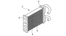
ここで、従来の熱交換器の構成例を図面に基づいて簡単に説明する。図17は車両用空気調和装置に用いられる熱交換器の一例としてヒータコアを示したものであり、図中の符号1はエンジン冷却水を導入して空気(熱交換流体)を加熱するヒータコア、2は左右一対のヘッダ、3は熱交換媒体としての温水を流す扁平チューブ、4は空気側の伝熱面積を増大させるコルゲートフィンである。
【0003】
上述した従来構成のヒータコア1では、ヘッダ2,2間を上下方向に間隙を設けて多段に並べた扁平チューブ3で連結し、隣接する扁平チューブ3,3間にはコルゲートフィン4を設置してある。ヘッダ2及び扁平チューブ3を流れる温水は、扁平チューブ3,3間を通過する空気を加熱するが、この時、コルゲートフィン4が空気への伝熱面積を増すことで熱交換効率の向上を図っている。
なお、従来の熱交換器では、上述した扁平チューブ3とコルゲートフィン4との組合せの他にも、プレートフィンと丸管とを組合せたものもあり、いずれの場合も冷媒や温水などの熱交換媒体と熱交換して冷却または加熱される空気側の伝熱面積を増すため、フィンを付加した構成となっている。
【0004】
【発明が解決しようとする課題】
ところで、近年の空気調和装置においては、空気調和装置自体の小型化、軽量化及び高効率化が望まれており、従って、冷凍サイクル中に設置される熱交換器についても、その効率を向上させることにより、小型化及び軽量化を達成することが求められている。
【0005】
本発明は、上記の事情に鑑みてなされたもので、小型化及び軽量化したフィンレス熱交換器の提供、そして、このフィンレス熱交換器に好適な熱交換チューブの提供を目的とするものである。
【0006】
【課題を解決するための手段】
本発明は、上記課題を解決するため、以下の手段を採用した。
請求項1に記載の熱交換チューブは、平行に配列された複数のチューブをリブでつなげて一体化した形状の多穴チューブの管群を成形し、ヘッダに挿入される軸方向両端部を残し前記リブを切断除去して、前記チューブの外側を流れる熱交換流体が流れる間隙を形成するように個々の隣接するチューブ間を分離させる熱交換チューブとし、前記チューブが、左右一対の前記ヘッダに連結されており、隣接する前記チューブは、前記軸方向両端部を除いて上下方向へ交互に移動させた千鳥配置とされていることを特徴とするものである。
【0007】
このような熱交換チューブによれば、多数のチューブをヘッダに組み付ける際において、複数のチューブの両端をリブでつなげた多穴チューブ(管群)として取り扱うことが可能になるので、保持や組み付け作業が容易になる。
また、両端部を除いてリブを切断除去したので、チューブの外側を流れて熱交換する空気等の熱交換流体を流す間隙が隣接するチューブ間を分離して形成され、この間隙を通過する熱交換流体の流れを各チューブの前面に当てて、チューブ内を流れる熱交換媒体と効率よく熱交換させることができる。
また、上述した熱交換チューブは、平行に配列された複数のチューブ(管群)が左右一対のヘッダに連結され、隣接するチューブは、平行に配列された軸方向両端部を除いて上下方向へ交互に移動させた千鳥配置にしたので、空気側の熱伝達率を向上させると共に、配列ピッチの自由度を増すことができる。
【0008】
このような熱交換チューブは、前記チューブの断面を円形または楕円形にするのが好ましく、円形の断面とすれば耐圧強度の面で有利になる。また、前記チューブを楕円形の断面とすれば、円形断面と比較して管外熱伝達率を向上させ、かつ、チューブ外を流れる空気流の圧損を低減させることができる。なお、より好ましくは、外周長に基づく相当直径で3mm以下の楕円管にするとよい。
【0009】
また、前記チューブは、前記円形または前記楕円形の半分に相当する分だけ移動させる前記チューブと、反対に前記円形または前記楕円形の半分に相当する分だけ下に移動させる前記チューブとを交互に配置させた千鳥配置とされていることが好ましい。
そして、前記多穴チューブを熱伝導性金属の押し出し成形品とすれば、熱交換チューブを容易に製造することができる。この場合、前記多穴チューブの成形が、押し出し成形工程と、前記リブの切断除去工程と、該切断除去工程後のプレス成形工程とを具備してなされることで、押し出し成形ができない形状のものであっても、プレス加工を加えることで成形可能となる。
また、前記チューブの断面形状を楕円形とし、内部に複数の円形断面流路を設けることで、楕円形の外形形状により管外熱伝達率及び空気流の圧損面で有利になり、かつ、内部には耐圧強度に優れている円形断面流路を複数設けることが可能になる。
【0010】
あるいは、前記多穴チューブが、半円形または楕円形の凹部と平面部とを交互に複数列設けた一対の熱伝導性金属よりなる板状部材を合わせて一体化したものでもよく、このような熱交換チューブは、チューブ肉厚を薄くできるなど押し出し成形に比べて設計の自由度が高くなる。
【0011】
上述した熱交換チューブは、前記熱伝導性金属がアルミニウムまたはアルミニウム合金製であることが好ましい。
また、上述した熱交換チューブにおいては、前記リブの切断除去を断続的に実施し、前記両端部以外に前記チューブ間の連結リブを設けて補強板として機能させてもよい。
また、上述した熱交換チューブにおいては、前記チューブを千鳥配置にすることで、空気側の熱伝達率を向上させる共に、配列ピッチの自由度を増すことができる。
【0012】
また、上述した熱交換チューブにおいては、前記チューブの外側を通過して流れる熱交換流体流れ方向の後流側に連なる水平部を残して前記リブの切断除去を実施すれば、チューブ後流側における空気流の剥離や渦の発生を低コストで抑制することができる。
また、上述した熱交換チューブにおいては、前記チューブの内周面に微細溝を設けることが好ましく、これにより、内周の表面積を増加させて管内側の伝熱性能を向上させることができる。
【0013】
請求項12に記載の熱交換チューブは、複数のチューブをリブでつなげた形状の多穴チューブを成形し、ヘッダに挿入される両端部を残し前記リブを切断除去して個々のチューブ間を分離させ、前記リブを前記チューブの軸方向に断続的に切断し、該切断部分を屈曲してスペーサとして活用することを特徴とするものである。
このような熱交換チューブによれば、多数のチューブをヘッダに組み付けする際、複数のチューブの両端をリブでつなげた多穴チューブ(管群)として取り扱うことが可能になるので、保持や組み付け作業が容易になる。また、両端部を除いてリブを切断除去したので、熱交換する空気等の熱交換流体の流れを各チューブの前面に当てて、チューブ内を流れる熱交換媒体と効率よく熱交換させることができる。さらに、リブをチューブの軸方向に断続的に切断し、該切断部分を折曲してスペーサとして活用するので、隣接するチューブとの間のピッチを定めるスペーサを一体的に設けることができる。
【0014】
請求項13に記載のフィンレス熱交換器は、左右一対のヘッダを有し、請求項1から12のいずれかに記載の熱交換チューブが、前記ヘッダに連結されて構成されることを特徴とするものである。
このようなフィンレス熱交換器によれば、熱交換チューブのチューブ間に形成された間隙を通過する熱交換流体の流れを各チューブの前面に当て、チューブ内を流れる熱交換媒体と効率よく熱交換させることができ、しかも、隣接するチューブを上下方向へ交互に移動させた千鳥配置により、空気側の熱伝達率を向上させることができる。さらに、フィンをなくしたことで金属間の熱抵抗がなくなるので、熱交換器の熱交換能力を向上させて小型化及び軽量化を可能にする。また、多数のチューブをヘッダに組み付ける際において、複数のチューブの両端をリブでつなげた多穴チューブ(管群)として取り扱うことが可能になるので、保持や組み付け作業が容易になる。
上述したフィンレス熱交換器においては、前記ヘッダに矩形断面の挿入穴を設け、前記熱交換チューブの両端に前記挿入穴の矩形断面に合わせるプレス加工を施すことが好ましく、これにより、ヘッダの挿入穴加工が容易になり、ヘッダの加工コストを低減できる。
【0015】
請求項14に記載のフィンレス熱交換器は、熱交換流体流路となる間隙を設けて配列した多数の熱交換媒体流路の細管によりヘッダ間を連結して構成され、前記多数の細管が、請求項1から12のいずれかに記載の熱交換チューブを組み合わせてなり、前記ヘッダに挿入穴を設け、前記熱交換チューブの両端に前記挿入穴に合わせたアダブタを取り付けたことを特徴とするものである。
このようなフィンレス熱交換器によれば、多数の細管を用いたことで管内側及び熱交換流体(空気等)側の熱伝達率が向上し、さらに、フィンをなくしたことで金属間の熱抵抗がなくなるので、熱交換器の熱交換能力を向上させて小型化及び軽量化を可能にする。この場合、前記多数の細管は、請求項1から12のいずれかに記載の熱交換チューブを組み合わせることが好ましい。
そして、上記のフィンレス熱交換器においては、ヘッダに挿入穴を設け、熱交換チューブの両端に挿入穴に合わせたアダプタを取り付けたので、ヘッダにおけるチューブの挿入穴加工が容易になり、製造コストの低減に貢献する。この場合、前記アダプタを2分割構造とするのが好ましく、これにより、熱交換チューブの端部を挟み込むようにしてアダプタを容易に取り付けることができる。また、前記挿入穴は矩形断面を有し、該矩形断面に合わせたアダブタを取り付けることが好ましい。
請求項18に記載のフィンレス熱交換器は、熱交換流体流路となる間隙を設けて配列した多数の熱交換媒体流路の細管によりヘッダ間を連結して構成され、前記多数の細管が、請求項1から12のいずれかに記載の熱交換チューブを組み合わせてなり、前記ヘッダに挿入穴を設け、前記熱交換チューブの両端を前記挿入穴に合わせて先細に変形させるプレス加工を施したことを特徴とするものである。
また、本発明のフィンレス熱交換器において、上述した細管は、外周長に基づく相当直径で3mm以下の楕円管であることが望ましい。
【0016】
【発明の実施の形態】
以下、本発明に係る熱交換チューブ及びフィンレス熱交換器の一実施形態を図面に基づいて説明する。
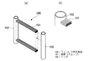
図12は本発明によるフィンレス熱交換器の構成を示す斜視図であり、図中の符号100はフィンレス熱交換器、101は熱交換媒体流路となる細管(チューブ)、102はヘッダを示している。このフィンレス熱交換器100は、左右一対のヘッダ102,102間を多数の細管101で連結した構成となっており、各細管101の間には空気(熱交換流体)流路となる間隙が設けられている。
【0017】
細管101には、図13に示すように、たとえば長径Lが2mm程度でかつ短径Sが1.2mm程度と細い楕円断面形状のものを採用し、長径Lと空気流れ方向とが平行となるように配置して使用する。そして、多数の細管101は、たとえば空気流れ方向にピッチP(たとえば2.4mm程度)で配置すると共に、上下方向に間隙H(たとえば1.9mm程度)を設けて千鳥状に配列されており、この結果、各細管101間には空気流路となる間隙が形成されている。
また、このようにして形成した各細管101間の隙間は、従来の熱交換器と異なり、コルゲートフィンなどのフィンを設けることなく空間部をそのまま空気流路として活用している。
【0018】
このような構成のフィンレス熱交換器100とすれば、冷媒等熱交換媒体の流路として楕円断面形状の細管101を多数配列したので、円形断面の細管と比較して、空気側の熱伝達率が向上する。そして、楕円形状細管は、円形細管と比較して空気流の剥離点が後方に移動するため、形状抵抗の大幅な低下により熱交換器を通過する空気流の圧力損失が低減され、結果として、細管101の稠密配置が可能となって高い熱交換能力を得ることができる。
また、径の小さい細管101を採用(細径化)したことで、管内側熱伝達率及び空気側熱伝達率が共に向上し、かつ細管101の外周面積及び内周面積の合計値が増加する。
さらに、細管101間にフィンを設けない構成としたので、金属抵抗(すなわちフィンと細管101との間の熱抵抗)がゼロとなり、これによる熱の損失をなくすことができる。
【0019】
従って、上述した空気側熱伝達率向上、管内側熱伝達率向上、空気圧損の低減及び金属抵抗の解消との相乗効果により、フィンレス熱交換器100の熱交換能力が向上する。このため、必要な熱交換能力を小型化及び軽量化した熱交換器で得ることが可能となり、熱交換器を設置するスペースの確保が容易になったり、熱交換器を備えた装置自体を小型化することもできる。
あるいは、フィンレス熱交換器100を従来と同様の大きさにすることで、熱交換能力の高い熱交換器として使用することも可能である。
【0020】
ところで、上述した楕円形状断面の細管101には、その外周長に基づく相当直径D0 に関して、細径化の最適値があることを見出しており、以下これについて説明する。
図16は、外周長に基づく相当直径D0 を1mm,2mm,3mmとした3種類の細管101についてその短径/長径比を変え、フィンレス熱交換器(ここではヒータコア)に用いた場合の実験結果を示したものであり、楕円の短径/長径比を横軸に、熱交換能力KA0 (W/K)を縦軸にとってある。ここで、熱交換能力KA0 において、Kは熱通過率、A0 は外表面積である。
なお、ここで使用しているヒータコアの熱交外寸は、W(横幅)160mm、H(高さ)145mm、D(奥行)25mmであり、正面風速3m/s、空気圧損140Pa、水量360l/hとして実験し、一方、比較用の従来品については、コルゲートフィンと扁平チューブとを組み合わせたものを使用している。
【0021】
この実験結果から、楕円形状断面の細管101としては、外周長に基づく相当直径D0 が3mm以下とするのが好ましい。これは、破線で示す従来品の熱交換能力を基準とした場合、従来品より熱交換能力が高い破線より上の領域は、楕円管として妥当な短径/長径比(0.5程度)より大きいものではD0 =3mmが限界となるためである。すなわち、D0 が3mmより大きくなると、短径/長径比を0.5より小さくしなければならず、従って、かなり扁平の楕円形状としなければ従来品の熱交換能力を上回ることができず好ましくない。なお、楕円の短径/長径比を1にすれば円となる。
【0022】
上述したフィンレス熱交換器100では、細管101内を熱交換媒体が流れるので、熱交換媒体がヘッダ102に設けた仕切部材の作用により左右に往復して流れるいわゆるマルチフロータイプとするよりは、一方のヘッダ102から他方のヘッダ102へ全量が一方向へ流れる1パス方式を採用し、圧損の低減を図ることが望ましい。
【0023】
なお、細管101の断面形状は、上述した楕円形状に限定されることはなく、たとえば円形断面や多角形断面のものを採用してもよいし、また、細管101の配置については必ずしも千鳥状とする必要はない。
【0024】
さて、上述したフィンレス熱交換器100では、多数の細管101をヘッダ102に挿入するものであるが、多数の細管101をヘッダ102に挿入する作業は、作業性や製造コストなどの面で難がある。そこで、上述したフィンレス熱交換器100に用いて好適な熱交換チューブ、すなわち複数のチューブを一体にまとめた多穴チューブの構成を以下に説明する。
図1は、熱交換チューブに係る第1の実施形態を示しており、図中の符号10は熱交換チューブ、11はチューブ、12はリブ、13はリブ除去部である。
【0025】
熱交換チューブ10は、複数のチューブ11をリブ12でつなげた形状の多穴チューブであり、上述したヘッダ102に挿入される両端部を残して中央部のリブ12を切断除去し、隣接するチューブ11間を分離状態にしたリブ除去部13を形成してある。
このように構成された熱交換チューブ10の製造は、たとえばアルミニウムまたはアルミニウム合金のような熱伝導性金属を押し出し成形することで、図2に示すように、平行に配列された複数(図示の例では6本)のチューブ11間をリブ12により連結して一体化した形状の熱交換チューブ基本体(多穴チューブ)10′とする。この後、チューブ11における軸方向両端部を残して中央部分のリブ12を切断除去すれば、6本のチューブ11が両端部でリブ12により一体化された管群の熱交換チューブ10となる。なお、リブ12を切断除去することにより生じた空間部分がリブ除去部13である。
【0026】
上述した熱交換チューブ10では、各チューブ11の断面形状として管外熱伝達率の向上や空気圧損の低減などに有利な楕円形を採用しているが、耐圧面で有利になる円形断面としてもよい。なお、チューブ11の断面形状については、楕円形や円形に限定されることはなく、たとえば多角形断面としてもよい。
【0027】
このような熱交換チューブ10をフィンレス熱交換器100に採用すれば、多数のチューブ101をヘッダ102に組み付けする作業に代えて、複数のチューブ11を一体化した多穴チューブの管群として取り扱うことができるので、組み付け作業時における保持や作業が容易になる。
また、両端部を除いてリブ12を切断除去したので、熱交換する空気の流れはリブ除去部13を通って各チューブ11の前面に当たり、チューブ11内を流れる熱交換媒体と効率よく熱交換させることができる。
なお、ここでのチューブ11の形状、寸法及び配列等については、上述した単独の細管101に関して説明したものを適用すればよい。
【0028】
そして、上述した熱交換チューブ10は、アルミニウム等の熱伝導性金属を押し出し成形することで容易に製造することができるため、組み付け作業性の向上と共に製造コストの低減に有効となる。
また、熱交換チューブ基本体10′の成形が押し出し成形工程のみでは困難な形状の場合には、図3に示すように、押し出し成形工程(a)及びリブ12の切断除去工程(b)に加えて、(c)に示すプレス成形工程を実施すればよい。このプレス成形工程は、最終的に望む外形形状とした成形型14a,14bによるプレス加工を熱交換チューブ基本体10′に施すものであり、たとえば円形断面のチューブ11を押し出し成形した後、プレス成形により楕円形断面とすることが可能である。
なお、図中の符号15は、リブ12を切断除去するカッタを示している。
【0029】
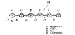
続いて、上述した熱交換チューブに関する第2の実施形態を図4に示して説明する。
この熱交換チューブ20は、チューブ21全体の断面形状を楕円形として複数をリブ22でつなぎ、各チューブ21の内部に複数(図示の例では二つ)の円形断面流路23を設けてある。このような構成の熱交換チューブ20とすれば、楕円形としたチューブ21の外形形状により管外熱伝達率及び空気流の圧損面で有利になり、かつ、内部には耐圧強度に優れている円形断面流路23を複数設けることが可能になる。
なお、図示の熱交換チューブ20は、リブ22を切断除去する前の断面形状を示しており、上述した第1の実施形態と同様の処理が施される。
【0030】
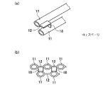
続いて、上述した熱交換チューブに関する第3の実施形態を図5に示して説明する。
この熱交換チューブ30は、半円形または楕円形の凹部31と平面部32とを交互に複数列設けた上下一対の板状部材33A,33Bを合わせて一体化したものであり、上下の凹部により形成される熱交換媒体の流路部(チューブに相当)34と平らなリブ相当部35とが交互に複数列形成される。この場合、重ね合わせる上下一対の平面部32間をろう付けするなどして一体化した後、同平面部32については一体化に必要な部分及び両端部を残して切断除去し、リブ除去部36を形成する。なお、板状部材33A,33Bについては、プレス成形により容易に成形することができる。
このような構成の熱交換チューブ30とすることにより、チューブに相当する流路部34の肉厚を薄くできるなど、押し出し成形に比べて設計の自由度が高くなるという利点がある。
【0031】
さて、上述した各実施形態の熱交換チューブ10,20,30は、熱伝導性金属としてアルミニウムまたはアルミニウム合金を用いたものが好ましく、押し出し加工等の成形性に優れ、良好な熱交換能力を得ることができる。しかし、上述した本発明はこれに限定されるものではなく、他の熱伝導性金属を採用可能なことはもちろんである。
【0032】
また、上述した各実施形態の熱交換チューブ10,20,30においては、リブ12,22及びリブ相当部35の切断除去については、図6に示す第1変形例のように、切断除去を断続的に実施してもよい。すなわち、両端部以外にもチューブ間を連結するための連結リブ16を適当なピッチで残し、熱交換チューブの撓みや変形を防止又は抑制する補強板として機能させてもよい。
なお、図6に示す変形例では、中央部の1箇所にのみ連結リブ16を設けてあるが、熱交換チューブの長さに応じて連結リブ16の数を増し、2箇所以上設けるようにしてもよい。
【0033】
また、上述した各実施形態の熱交換チューブ10,20,30においては、図7に示す第2変形例のように、隣接するチューブ11を上下方向へ交互に移動させ、千鳥配置にするとよい。すなわち、図7(a)に想像線で示す成形当初のチューブ位置から、ほぼ短径の半分に相当する分だけ上に変形移動させるチューブ11aと、反対にほぼ短径の半分に相当する分だけ下に変形移動させるチューブ11bとを交互に配置する。
このようにチューブ11を千鳥配置とすれば、各チューブ11a,11bの先端に空気流が当たりやすくなるので、空気側の熱伝達率をより一層向上させることができると共に、チューブの配列ピッチに関する設計上の自由度を増すことができる。
【0034】
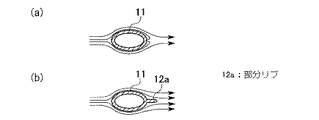
また、上述した各実施形態の熱交換チューブ10,20,30においては、図8(b)に示す第3変形例のように、チューブ11の後流側に水平部となる部分リブ12aを部分的に残してもよい。この部分リブ12aは、チューブ11の外側を図中に矢印で示すように通過して流れる空気(熱交換流体)流れ方向において、その後流側に連なるリブ12の一部をチューブ11につなげた状態で残し、他を切断除去することで形成したものである。すなわち、上述したリブ12の切断除去範囲を狭めるだけであり、実質的な工数の増加はなく低コストで容易に実施できる。
このような図8(b)の構成とすれば、図8(a)に示すように部分リブ12aがない場合と比較して、チューブ後流側における空気流の剥離や渦の発生が抑制されるので、空気流の圧力損失を低コストで低減することができる。
【0035】
なお、図8(b)に示した第3変形例のように空気流の圧力損失を低減させるためには、たとえば図9に示す他の実施例のように、リブ12の切断除去工程をなくし、全面的にリブ12を残すようにしてもよい。この場合、リブ12が全面的に存在しているため熱伝達率の面では不利になる反面、リブ12がチューブ後流側における空気流の剥離や渦の発生を抑制し、しかも、製造工程が減ることから、より低コストで圧力損失を低減できるという利点がある。すなわち、この場合の熱交換チューブ10は、図2に示した熱交換チューブ基本体10′と実質的に同じものとなる。
【0036】
また、上述した各実施形態の熱交換チューブ10,20,30においては、たとえば図10に示す第4変形例のように、チューブ11の内周面に微細溝17を設けることが好ましい。この微細溝17は、第1及び第2の実施形態では押し出し成形と同時に軸方向(押し出し方向)へ設けることが可能であり、第3の実施形態では、板状部材33A,33Bのプレス整形と同時に所望の方向に形成することが可能である。
このような微細溝17を設けたチューブとすることにより、内周の表面積が増加する分管内側の伝熱性能を向上させることができる。
【0037】
また、上述した各実施形態の熱交換チューブ10,20,30においては、たとえば図11に示す第5変形例のように、リブ12を隣接するチューブ11に沿って軸方向へ断続的に切断しておき、この切断部分を下向きに折曲してスペーサ18として活用する。これにより、上下方向に隣接するチューブ11間のピッチ(図13における間隙H)を容易に規定できるようにしたスペーサ18を、熱交換チューブと一体的に設けることができる。
【0038】
さて、上述した各実施形態の熱交換チューブ10,20,30をフィンレス熱交換器100のヘッダ102に挿入する部分の構成例に関し、その好適な実施形態を図14及び図15に示して説明する。
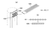
図14に示す第1の実施形態では、ヘッダ102に矩形断面の挿入穴103を多段に設けておき、一方、熱交換チューブ10側では、両端を挿入穴103の矩形断面に合わせるためにプレス加工を施す。すなわち、図14(b)に示すように、熱交換チューブ10を先端側の正面から見た形状が挿入穴103と一致する矩形となるように変形させた熱交換チューブ10Aとする。
このようにプレス加工を施した熱交換チューブ10Aとすることにより、ヘッダ102側に設ける挿入穴103の形状を単純な矩形形状とすることができ、従って、挿入穴103の加工が容易になり、ヘッダ102の加工コストを低減できる。なお、上下に隣接する挿入穴103については、チューブ11の配置が千鳥状となるよう左右に交互にずらして設けておくとよい。
【0039】
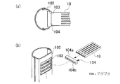
図15に示す第2の実施形態では、ヘッダ102に矩形断面の挿入穴103を同様に設け、熱交換チューブ10の両端にそれぞれ挿入穴103の矩形断面に合わせたアダプタ104を取り付けておく。
このような構成としても、ヘッダ102におけるチューブ10の挿入穴加工が容易になり、製造コストの低減に貢献することができる。なお、この場合においては、アダプタ104をチューブ11の配列方向と平行に2分割した構造とするのが好ましく、これにより、熱交換チューブ10の端部を上下から挟み込むようにしてアダプタ104を容易に取り付けることができる。
【0040】
なお、本発明は上述した実施形態に限定されるものではなく、発明の要旨を逸脱しない範囲で設計変更可能であることは言うまでもない。
【0041】
【発明の効果】
上述した本発明の熱交換チューブ及びフィンレス熱交換器によれば、以下の効果を奏する。
(1) 多数の細管を用いてヘッダ間を連結すると共に、フィンを全く用いない構成のフィンレス熱交換器としたので、管内側熱伝達率及び空気側熱伝達率が共に向上し、かつ、金属抵抗がゼロとなる。このため、熱交換器の熱交換能力が向上し、熱交換器を小型化及び軽量化することが可能となる。
(2) 特に、細管(チューブ)として外周長に基づく相当直径が3mm以下の楕円形断面(楕円チューブ)を採用すれば、円形断面と比較して空気側熱伝達率が向上し、かつ、空気流の圧力損失も低減するので、この点からも熱交換器の熱交換能力が向上し、小型化及び軽量化に貢献できる。
(3) 複数のチューブを一体化した熱交換チューブを採用すれば、フィンレス熱交換器のヘッダに細管を組み付けする際、多数のチューブの保持や組み付け作業が容易になる。このため、フィンレス熱交換器の製造コストを低下させ、安価に製造できるようになる。
【図面の簡単な説明】
【図1】 本発明に係る熱交換チューブの第1の実施形態を示す図であり、(a)は全体構成を示す斜視図、(b)は(a)のA−A断面図である。
【図2】 図1の熱交換チューブが押し出し成形された状態にある熱交換チューブ基本体を示す図であり、(a)は平面図、(b)は(a)のB−B断面図である。
【図3】 図1に示す熱交換チューブに係る製造工程の変形例を示す図で、(a)は押し出し成形工程、(b)は切断除去工程、(c)はプレス加工工程を示す説明図である。
【図4】 本発明に係る熱交換チューブの第2の実施形態を示す断面図である。
【図5】 本発明に係る熱交換チューブの第3の実施形態を示す図であり、(a)は部品段階の板状部材を示す斜視図、(b)は板状部材を合わせて一体化した状態を示す断面図、(c)は切断除去後の完成状態を示す断面図である。
【図6】 本発明による熱交換チューブの第1〜第3の実施形態に係る第1変形例を示す平面図である。
【図7】 本発明による熱交換チューブの第1〜第3の実施形態に係る第2変形例を示す図であり、(a)は断面図、(b)は(a)の左側面図である。
【図8】 本発明による熱交換チューブの第1〜第3の実施形態に係る第3変形例に関する図であり、(a)は部分リブがない場合の断面図、(b)は部分リブを設けた第3変形例を示す断面図である。
【図9】 図8(b)に示した第3変形例に関する他の実施例を示す断面図である。
【図10】 本発明による熱交換チューブの第1〜第3の実施形態に係る第4変形例を示すである。
【図11】 本発明による熱交換チューブの第1〜第3の実施形態に係る第5変形例を示す図であり、(a)は要部斜視図、(b)は先端側から見た要部正面図である。
【図12】 本発明に係るフィンレス熱交換器の一実施形態を示す図であり、(a)は斜視図、(b)は(a)の要部拡大図である。
【図13】 図12のフィンレス熱交換器に用いられている細管を示す図であり、(a)は断面図、(b)は細管配列例を示す図である。
【図14】 熱交換チューブをヘッダに挿入する部分の構成に関する第1の実施形態を示す図であり、(a)は分解斜視図、(b)は熱交換チューブ先端のプレス加工による変形を示す図である。
【図15】 熱交換チューブをヘッダに挿入する部分の構成に関する第2の実施形態を示す図であり、(a)は断面図、(b)は分解斜視図である。
【図16】 本発明におけるフィンレス熱交換器において、楕円の短径/長径比と熱交換能力(KA0 )との関係を示す実験結果の図である。
【図17】 従来の熱交換器の構成例を示す斜視図である。
【符号の説明】
10,20,30 熱交換チューブ
11,21 チューブ
12,22 リブ
12a 部分リブ
16 連結リブ
17 微細溝
18 スペーサ
23 円形断面流路
31 凹部
32 平面部
33A,33B 板状部材
34 流路部(チューブに相当)
35 リブ相当部
100 フィンレス熱交換器
101 細管(チューブ)
102 ヘッダ
103 挿入穴
104 アダプタ[0001]
BACKGROUND OF THE INVENTION
The present invention relates to a heat exchange tube for a heat exchanger used in an air conditioner or the like and a finless heat exchanger using the heat exchange tube, and in particular, a technique suitable for downsizing and weight reduction of the heat exchanger. About.
[0002]
[Prior art]
Conventionally, in an air conditioner for a vehicle or the like, a heat exchanger such as a condenser, an evaporator, and a heater core is used in the refrigeration cycle.
Here, the structural example of the conventional heat exchanger is demonstrated easily based on drawing. FIG. 17 shows a heater core as an example of a heat exchanger used in a vehicle air conditioner. Reference numeral 1 in the drawing denotes a heater core that heats air (heat exchange fluid) by introducing engine coolant. Is a pair of left and right headers, 3 is a flat tube through which hot water as a heat exchange medium flows, and 4 is a corrugated fin that increases the heat transfer area on the air side.
[0003]
In the heater core 1 of the conventional configuration described above, the
In addition to the combination of the flat tube 3 and the corrugated fin 4 described above, there is a conventional heat exchanger in which a plate fin and a round tube are combined. In order to increase the heat transfer area on the air side that is cooled or heated by exchanging heat with the medium, fins are added.
[0004]
[Problems to be solved by the invention]
By the way, in recent air conditioners, it is desired to reduce the size, weight and efficiency of the air conditioner itself. Therefore, the efficiency of a heat exchanger installed in a refrigeration cycle is also improved. Therefore, it is required to achieve a reduction in size and weight.
[0005]
The present invention has been made in view of the above circumstances, and an object thereof is to provide a finless heat exchanger that is reduced in size and weight, and to provide a heat exchange tube that is suitable for the finless heat exchanger. .
[0006]
[Means for Solving the Problems]
The present invention employs the following means in order to solve the above problems.
The heat exchange tube according to claim 1,Arranged in parallelConnect multiple tubes with ribsIntegratedShaped multi-hole tubeTube groupIs molded and inserted into the headerAxial directionCut and remove the ribs leaving both endsForming a gap through which the heat exchange fluid flowing outside the tube flows.IndividualAdjacentHeat exchange tube that separates tubesThe tubes are connected to the pair of left and right headers, and the adjacent tubes are arranged in a zigzag arrangement alternately moved in the vertical direction except for both axial end portions.It is characterized by this.
[0007]
According to such a heat exchange tube, when assembling a large number of tubes to the header, it becomes possible to handle them as a multi-hole tube (tube group) in which both ends of a plurality of tubes are connected by ribs. Becomes easier.
Also, since the ribs were cut and removed except for both ends,A gap through which heat exchange fluid such as air that flows outside the tube to exchange heat is formed separately between adjacent tubes, and the flow of heat exchange fluid that passes through this gapIt is possible to efficiently exchange heat with the heat exchange medium flowing in the tube by being applied to the front surface of each tube.
In addition, in the heat exchange tube described above, a plurality of tubes (tube groups) arranged in parallel are connected to a pair of left and right headers, and adjacent tubes are vertically moved except for both axial ends arranged in parallel. Since the staggered arrangement is moved alternately, the heat transfer rate on the air side can be improved and the degree of freedom of the arrangement pitch can be increased.
[0008]
In such a heat exchange tube, it is preferable that the tube has a circular or elliptical cross section, and a circular cross section is advantageous in terms of pressure resistance. Further, if the tube has an elliptical cross section, the heat transfer coefficient outside the tube can be improved and the pressure loss of the air flow flowing outside the tube can be reduced as compared with the circular cross section. More preferably, an elliptical tube having an equivalent diameter based on the outer peripheral length of 3 mm or less may be used.
[0009]
In addition, the tube is alternately moved by the tube corresponding to the half of the circle or the ellipse and the tube moved downward by the amount corresponding to the half of the circle or the ellipse. It is preferable that the arrangement is a staggered arrangement.
And if the said multi-hole tube is made into the extrusion molding product of a heat conductive metal, a heat exchange tube can be manufactured easily. In this case, the multi-hole tube has a shape that cannot be extruded by forming an extrusion molding process, a cutting and removing process of the rib, and a press molding process after the cutting and removing process. Even so, it can be formed by applying press working.
Further, by providing the tube with an elliptical cross-sectional shape and providing a plurality of circular cross-sectional flow passages therein, the elliptical outer shape is advantageous in terms of the heat transfer coefficient outside the tube and the pressure loss surface of the air flow, and the internal It is possible to provide a plurality of circular cross-sectional flow paths having excellent pressure strength.
[0010]
Alternatively, the multi-hole tube may be formed by integrating a pair of plate-like members made of a heat conductive metal in which a plurality of rows of alternating semicircular or elliptical concave portions and flat portions are provided. The heat exchange tube has a higher degree of design freedom than extrusion molding because the tube thickness can be reduced.
[0011]
In the heat exchange tube described above, the heat conductive metal is preferably made of aluminum or an aluminum alloy.
In the heat exchange tube described above, the rib may be cut and removed intermittently, and a connecting rib between the tubes may be provided in addition to the both end portions to function as a reinforcing plate.
Moreover, in the heat exchange tube mentioned above, by arranging the tubes in a staggered arrangement, the heat transfer coefficient on the air side can be improved and the degree of freedom of the arrangement pitch can be increased.
[0012]
Further, in the heat exchange tube described above, if the ribs are cut and removed while leaving the horizontal portion connected to the wake side in the heat exchange fluid flow direction flowing through the outside of the tube, Air flow separation and vortex generation can be suppressed at low cost.
Moreover, in the heat exchange tube mentioned above, it is preferable to provide a fine groove on the inner peripheral surface of the tube, thereby increasing the surface area of the inner periphery and improving the heat transfer performance inside the tube..
[0013]
The heat exchange tube according to claim 12 forms a multi-hole tube having a shape in which a plurality of tubes are connected by ribs, and separates the individual tubes by cutting and removing the ribs leaving both ends inserted into the header. The rib is cut intermittently in the axial direction of the tube, and the cut portion is bent and used as a spacer.
According to such a heat exchange tube, when assembling a large number of tubes to the header, it becomes possible to handle them as a multi-hole tube (tube group) in which both ends of a plurality of tubes are connected by ribs. Becomes easier. Further, since the ribs are cut and removed except for both ends, the flow of heat exchange fluid such as air for heat exchange can be applied to the front surface of each tube to efficiently exchange heat with the heat exchange medium flowing in the tube. . Furthermore, since the rib is intermittently cut in the axial direction of the tube and the cut portion is bent and used as a spacer, a spacer that determines the pitch between adjacent tubes can be provided integrally.
[0014]
The finless heat exchanger according to
According to such a finless heat exchanger,The flow of heat exchange fluid passing through the gap formed between the tubes of the heat exchange tubes can be applied to the front surface of each tube to efficiently exchange heat with the heat exchange medium flowing in the tubes. By the staggered arrangement alternately moved in the vertical direction, the heat transfer rate on the air side can be improved.Further, since the heat resistance between the metals is eliminated by eliminating the fins, the heat exchanging ability of the heat exchanger is improved, thereby enabling a reduction in size and weight.In addition, when assembling a large number of tubes to the header, it becomes possible to handle them as a multi-hole tube (tube group) in which both ends of a plurality of tubes are connected by ribs, so that holding and assembling operations are facilitated.
In the finless heat exchanger described above, it is preferable that an insertion hole having a rectangular cross section is provided in the header, and press processing is performed on both ends of the heat exchange tube so as to match the rectangular cross section of the insertion hole. Processing becomes easy and the processing cost of the header can be reduced.
[0015]
The finless heat exchanger according to claim 14 is configured by connecting headers by a plurality of heat exchange medium flow passages arranged with gaps serving as heat exchange fluid flow passages, and the plurality of thin tubes are A combination of the heat exchange tubes according to any one of claims 1 to 12, wherein an insertion hole is provided in the header, and adapters adapted to the insertion holes are attached to both ends of the heat exchange tube. It is.
According to such a finless heat exchanger, the heat transfer coefficient on the inside of the tube and the heat exchange fluid (air, etc.) side is improved by using a large number of thin tubes, and furthermore, the heat between the metals is eliminated by eliminating the fins. Since there is no resistance, the heat exchanging ability of the heat exchanger is improved to enable miniaturization and weight reduction. In this case, it is preferable that the large number of thin tubes be combined with the heat exchange tube according to any one of claims 1 to 12.
And in said finless heat exchanger, since the insertion hole was provided in the header and the adapter matched with the insertion hole was attached to the both ends of the heat exchange tube, the insertion hole processing of the tube in the header became easy, and the manufacturing cost was reduced. Contributes to reduction. In this case, it is preferable that the adapter has a two-part structure, whereby the adapter can be easily attached so as to sandwich the end portion of the heat exchange tube. Moreover, it is preferable that the insertion hole has a rectangular cross section, and an adapter that matches the rectangular cross section is attached.
The finless heat exchanger according to
Moreover, in the finless heat exchanger of the present invention, the above-described thin tube is preferably an elliptic tube having an equivalent diameter based on the outer peripheral length of 3 mm or less.
[0016]
DETAILED DESCRIPTION OF THE INVENTION
Hereinafter, one embodiment of the heat exchange tube and finless heat exchanger concerning the present invention is described based on a drawing.
FIG. 12 is a perspective view showing a configuration of a finless heat exchanger according to the present invention, in which reference numeral 100 denotes a finless heat exchanger, 101 denotes a thin tube (tube) serving as a heat exchange medium flow path, and 102 denotes a header. Yes. The
[0017]
As shown in FIG. 13, the
Further, unlike the conventional heat exchanger, the gaps between the
[0018]
In the
Further, by adopting (thinning the diameter) the
Further, since the fins are not provided between the
[0019]
Therefore, the heat exchange capability of the
Alternatively, the
[0020]
By the way, the above-mentioned
FIG. 16 shows the equivalent diameter D based on the outer peripheral length.0 3 shows the experimental results when three types of
The heat exchange outer dimensions of the heater core used here are W (width) 160 mm, H (height) 145 mm, D (depth) 25 mm, front wind speed 3 m / s, air pressure loss 140 Pa, water volume 360 l / On the other hand, as a conventional product for comparison, a combination of a corrugated fin and a flat tube is used.
[0021]
From this experimental result, the
[0022]
In the
[0023]
The cross-sectional shape of the
[0024]
In the
FIG. 1 shows a first embodiment relating to a heat exchange tube. In FIG. 1,
[0025]
The
The
[0026]
In the
[0027]
If such a
Further, since the
In addition, what was demonstrated regarding the single
[0028]
And since the
Further, in the case where it is difficult to form the heat exchange tube basic body 10 'only by the extrusion molding process, as shown in FIG. 3, in addition to the extrusion molding process (a) and the
[0029]
Next, a second embodiment relating to the heat exchange tube described above will be described with reference to FIG.
In this
The illustrated
[0030]
Next, a third embodiment relating to the above-described heat exchange tube will be described with reference to FIG.
This
By using the
[0031]
The
[0032]
Further, in the
In the modification shown in FIG. 6, the connecting
[0033]
Moreover, in the
If the
[0034]
Moreover, in the
With the configuration shown in FIG. 8B, the separation of the air flow and the generation of vortices on the downstream side of the tube are suppressed as compared with the case where the
[0035]
In order to reduce the pressure loss of the air flow as in the third modified example shown in FIG. 8B, the step of cutting and removing the
[0036]
Moreover, in the
By making the tube provided with such a
[0037]
Moreover, in the
[0038]
Now, regarding a configuration example of a portion where the
In the first embodiment shown in FIG. 14, insertion holes 103 having a rectangular cross section are provided in the
By making the
[0039]
In the second embodiment shown in FIG. 15, the
Even with such a configuration, the insertion hole processing of the
[0040]
The present invention is not limited to the above-described embodiment, and it goes without saying that the design can be changed without departing from the gist of the invention.
[0041]
【The invention's effect】
The above-described heat exchange tube and finless heat exchanger of the present invention have the following effects.
(1) Since the finless heat exchanger has a structure in which the headers are connected by using a large number of thin tubes and no fins are used, both the heat transfer coefficient inside the tube and the heat transfer coefficient on the air side are improved. Resistance becomes zero. For this reason, the heat exchange capability of the heat exchanger is improved, and the heat exchanger can be reduced in size and weight.
(2) In particular, if an elliptical cross section (elliptical tube) having an equivalent diameter of 3 mm or less based on the outer peripheral length is adopted as the thin tube (tube), the air side heat transfer coefficient is improved as compared with the circular cross section, and the air Since the pressure loss of the flow is also reduced, the heat exchange capability of the heat exchanger is improved from this point as well, which can contribute to miniaturization and weight reduction.
(3) If a heat exchange tube in which a plurality of tubes are integrated is employed, a large number of tubes can be easily held and assembled when the thin tubes are assembled to the header of the finless heat exchanger. For this reason, the manufacturing cost of a finless heat exchanger can be reduced and can be manufactured at low cost.
[Brief description of the drawings]
1A and 1B are views showing a first embodiment of a heat exchange tube according to the present invention, in which FIG. 1A is a perspective view showing an overall configuration, and FIG. 1B is a cross-sectional view taken along line AA in FIG.
FIG. 2 is a view showing a heat exchange tube basic body in a state where the heat exchange tube of FIG. 1 is extruded, (a) is a plan view, and (b) is a sectional view taken along line BB of (a). is there.
3 is a view showing a modification of the manufacturing process related to the heat exchange tube shown in FIG. 1, wherein (a) is an extrusion molding process, (b) is a cutting and removing process, and (c) is an explanatory view showing a pressing process. It is.
FIG. 4 is a cross-sectional view showing a second embodiment of a heat exchange tube according to the present invention.
5A and 5B are views showing a third embodiment of a heat exchange tube according to the present invention, in which FIG. 5A is a perspective view showing a plate-like member at a component stage, and FIG. Sectional drawing which shows the state which carried out, (c) is sectional drawing which shows the completion state after cutting removal.
FIG. 6 is a plan view showing a first modification of the first to third embodiments of the heat exchange tube according to the present invention.
7A and 7B are views showing a second modification of the heat exchange tube according to the first to third embodiments of the present invention, wherein FIG. 7A is a cross-sectional view, and FIG. 7B is a left side view of FIG. is there.
FIG. 8 is a view relating to a third modification of the first to third embodiments of the heat exchange tube according to the present invention, in which (a) is a cross-sectional view when there is no partial rib, and (b) is a partial rib. It is sectional drawing which shows the 3rd modification provided.
FIG. 9 is a cross-sectional view showing another embodiment related to the third modification shown in FIG.
FIG. 10 shows a fourth modification of the first to third embodiments of the heat exchange tube according to the present invention.
FIGS. 11A and 11B are views showing a fifth modified example according to the first to third embodiments of the heat exchange tube according to the present invention, wherein FIG. 11A is a perspective view of a main part, and FIG. FIG.
12A and 12B are views showing an embodiment of a finless heat exchanger according to the present invention, in which FIG. 12A is a perspective view and FIG. 12B is an enlarged view of a main part of FIG.
13A and 13B are diagrams showing thin tubes used in the finless heat exchanger of FIG. 12, in which FIG. 13A is a cross-sectional view, and FIG.
FIGS. 14A and 14B are views showing a first embodiment relating to a configuration of a portion in which a heat exchange tube is inserted into a header, wherein FIG. 14A is an exploded perspective view, and FIG. FIG.
FIGS. 15A and 15B are views showing a second embodiment relating to a configuration of a portion where a heat exchange tube is inserted into a header, wherein FIG. 15A is a cross-sectional view, and FIG. 15B is an exploded perspective view.
FIG. 16 shows the ellipse minor axis / major axis ratio and heat exchange capacity (KA) in the finless heat exchanger of the present invention.0 It is a figure of the experimental result which shows the relationship between these.
FIG. 17 is a perspective view showing a configuration example of a conventional heat exchanger.
[Explanation of symbols]
10, 20, 30 Heat exchange tube
11,21 tube
12,22 rib
12a Partial rib
16 connecting ribs
17 Fine groove
18 Spacer
23 Circular cross-section flow path
31 recess
32 Plane section
33A, 33B Plate member
34 Channel section (equivalent to tube)
35 Rib equivalent part
100 finless heat exchanger
101 tubule
102 header
103 Insertion hole
104 adapter
Claims (19)
前記チューブが、左右一対の前記ヘッダに連結されており、隣接する前記チューブは、前記軸方向両端部を除いて上下方向へ交互に移動させた千鳥配置とされていることを特徴とする熱交換チューブ。 A plurality of tubes arranged in parallel are connected by ribs to form a tube group of multi-hole tubes , and the ribs are cut and removed leaving both axial ends inserted into the header . A heat exchange tube that separates each adjacent tube so as to form a gap through which the heat exchange fluid flowing outside flows ;
The tubes are connected to a pair of left and right headers, and the adjacent tubes are arranged in a staggered arrangement alternately moved in the vertical direction except for both axial end portions. tube.
Priority Applications (1)
| Application Number | Priority Date | Filing Date | Title |
|---|---|---|---|
| JP2000354062A JP4451981B2 (en) | 2000-11-21 | 2000-11-21 | Heat exchange tube and finless heat exchanger |
Applications Claiming Priority (1)
| Application Number | Priority Date | Filing Date | Title |
|---|---|---|---|
| JP2000354062A JP4451981B2 (en) | 2000-11-21 | 2000-11-21 | Heat exchange tube and finless heat exchanger |
Publications (2)
| Publication Number | Publication Date |
|---|---|
| JP2002153931A JP2002153931A (en) | 2002-05-28 |
| JP4451981B2 true JP4451981B2 (en) | 2010-04-14 |
Family
ID=18826719
Family Applications (1)
| Application Number | Title | Priority Date | Filing Date |
|---|---|---|---|
| JP2000354062A Expired - Lifetime JP4451981B2 (en) | 2000-11-21 | 2000-11-21 | Heat exchange tube and finless heat exchanger |
Country Status (1)
| Country | Link |
|---|---|
| JP (1) | JP4451981B2 (en) |
Cited By (2)
| Publication number | Priority date | Publication date | Assignee | Title |
|---|---|---|---|---|
| WO2014171095A1 (en) | 2013-04-16 | 2014-10-23 | パナソニック株式会社 | Heat exchanger |
| CN110579130A (en) * | 2013-03-01 | 2019-12-17 | 萨帕股份公司 | Multiport extrusion (MPE) design |
Families Citing this family (23)
| Publication number | Priority date | Publication date | Assignee | Title |
|---|---|---|---|---|
| KR20040019428A (en) * | 2002-08-26 | 2004-03-06 | 한라공조주식회사 | A tube for heat exchanger |
| US9581380B1 (en) | 2007-07-20 | 2017-02-28 | Carlos Quesada Saborio | Flexible refrigeration platform |
| KR101451234B1 (en) * | 2008-04-11 | 2014-10-15 | 한라비스테온공조 주식회사 | A Finless Heat Exchanger |
| US9285147B1 (en) | 2009-09-14 | 2016-03-15 | Carlos Quesada Saborio | Relocatable refrigeration system with pendulum within separator and accumulator chambers |
| WO2012028173A2 (en) * | 2010-08-31 | 2012-03-08 | Luvata Espoo Oy | A method for producing a channel arrangement, a channel arrangement, use of a channel arrangement and a metal profile |
| US20140027098A1 (en) * | 2011-04-14 | 2014-01-30 | Carrier Corporation | Heat exchanger |
| US9874408B2 (en) | 2012-11-30 | 2018-01-23 | Carlos Quesada Saborio | Heat exchangers |
| EP2738505A1 (en) * | 2012-11-30 | 2014-06-04 | Carlos Quesada Saborio | Tubing element for a heat exchanger means |
| KR101390460B1 (en) | 2013-06-04 | 2014-05-27 | 장한기술 주식회사 | Dehumidified cooling heat exchanger having circular multi-channel panel and special distribution type |
| JP2015034663A (en) * | 2013-08-08 | 2015-02-19 | サンデン株式会社 | Heat exchanger and heat cycle apparatus including heat exchanger |
| JP2015034660A (en) * | 2013-08-08 | 2015-02-19 | サンデン株式会社 | Heat exchanger |
| JP2015034662A (en) * | 2013-08-08 | 2015-02-19 | サンデン株式会社 | Heat exchanger |
| CN105091630A (en) * | 2014-05-16 | 2015-11-25 | 松下知识产权经营株式会社 | Heat exchanger and heat exchanging unit |
| JP6278010B2 (en) * | 2015-08-17 | 2018-02-14 | ダイキン工業株式会社 | Refrigerant shunt |
| DE102015217780A1 (en) * | 2015-09-17 | 2017-03-23 | Robert Bosch Gmbh | Method for producing a cooling device for cooling batteries |
| JP6894200B2 (en) * | 2016-06-29 | 2021-06-30 | 東芝産業機器システム株式会社 | Heat sink for electrical equipment |
| EP3663692B1 (en) | 2017-08-03 | 2021-03-24 | Mitsubishi Electric Corporation | Heat exchanger and refrigeration cycle apparatus |
| CN108534395A (en) * | 2018-05-17 | 2018-09-14 | 广东美的制冷设备有限公司 | Heat exchanger and air conditioner with it |
| CN110608552A (en) * | 2018-06-15 | 2019-12-24 | 杭州三花微通道换热器有限公司 | Heat exchange system |
| KR102635680B1 (en) * | 2019-04-03 | 2024-02-14 | 한온시스템 주식회사 | Heat exchanger and manufacturing method for manufacturing the same |
| CN111220007A (en) * | 2019-11-29 | 2020-06-02 | 四川金象赛瑞化工股份有限公司 | Heat exchange plate, heat exchanger, application of heat exchanger and washing cooling tower |
| EP4160112A4 (en) * | 2020-06-01 | 2023-07-26 | Mitsubishi Electric Corporation | Heat exchanger and refrigeration cycle apparatus |
| KR102408191B1 (en) * | 2020-10-22 | 2022-06-13 | 강림중공업 주식회사 | Boiler |
-
2000
- 2000-11-21 JP JP2000354062A patent/JP4451981B2/en not_active Expired - Lifetime
Cited By (3)
| Publication number | Priority date | Publication date | Assignee | Title |
|---|---|---|---|---|
| CN110579130A (en) * | 2013-03-01 | 2019-12-17 | 萨帕股份公司 | Multiport extrusion (MPE) design |
| WO2014171095A1 (en) | 2013-04-16 | 2014-10-23 | パナソニック株式会社 | Heat exchanger |
| US9766015B2 (en) | 2013-04-16 | 2017-09-19 | Panasonic Intellectual Property Management Co., Ltd. | Heat exchanger |
Also Published As
| Publication number | Publication date |
|---|---|
| JP2002153931A (en) | 2002-05-28 |
Similar Documents
| Publication | Publication Date | Title |
|---|---|---|
| JP4451981B2 (en) | Heat exchange tube and finless heat exchanger | |
| EP2810010B1 (en) | Multiple tube bank heat exchanger assembly and fabrication method | |
| US20060168812A1 (en) | Method of forming heat exchanger tubing and tubing formed thereby | |
| JPH11226685A (en) | Manufacture of heat exchanger and header tank | |
| AU4018999A (en) | Heat exchanger | |
| US8393385B2 (en) | Heat exchanging apparatus and method of making same | |
| JP4751662B2 (en) | Plate for manufacturing flat tube, method for manufacturing flat tube, and method for manufacturing heat exchanger | |
| JPH07190661A (en) | Heat exchanger | |
| AU2004261893A1 (en) | Heat exchanger | |
| US8307886B2 (en) | Heat exchanging device and method of making same | |
| KR20140110968A (en) | Heat exchanger utilizing tubular structures having internal flow altering members and external chamber assemblies | |
| US6364006B1 (en) | Beaded plate for a heat exchanger and method of making same | |
| CN101655323A (en) | Cross-counterflow heat exchanger assembly | |
| JP6806187B2 (en) | Heat exchanger | |
| US20130098590A1 (en) | Heat Exchanger with heat exchange chambers and plate members utilizing respective medium directing members and method of making same | |
| JP2000018867A (en) | Tube material for heat exchanger and heat exchanger | |
| JP4448354B2 (en) | Heat exchanger | |
| US20110030936A1 (en) | Heat Exchanging Apparatus and Method of Making Same | |
| JP2018124034A (en) | Tube for heat exchanger | |
| US6209629B1 (en) | Beaded plate for a heat exchanger and method of making same | |
| WO2019203115A1 (en) | Flat multi-hole tube, heat exchanger, and method for manufacturing heat exchanger | |
| JP6377628B2 (en) | Finned tube element, method for manufacturing the same, and heat exchanger provided with finned tube element | |
| CN212058426U (en) | Heat exchanger | |
| EP1710528A1 (en) | Heat exchanger | |
| US20220243986A1 (en) | Ccf heater core assembly |
Legal Events
| Date | Code | Title | Description |
|---|---|---|---|
| A621 | Written request for application examination |
Free format text: JAPANESE INTERMEDIATE CODE: A621 Effective date: 20070730 |
|
| A977 | Report on retrieval |
Free format text: JAPANESE INTERMEDIATE CODE: A971007 Effective date: 20090918 |
|
| A131 | Notification of reasons for refusal |
Free format text: JAPANESE INTERMEDIATE CODE: A131 Effective date: 20090929 |
|
| A521 | Written amendment |
Free format text: JAPANESE INTERMEDIATE CODE: A523 Effective date: 20091130 |
|
| TRDD | Decision of grant or rejection written | ||
| A01 | Written decision to grant a patent or to grant a registration (utility model) |
Free format text: JAPANESE INTERMEDIATE CODE: A01 Effective date: 20100105 |
|
| A01 | Written decision to grant a patent or to grant a registration (utility model) |
Free format text: JAPANESE INTERMEDIATE CODE: A01 |
|
| A61 | First payment of annual fees (during grant procedure) |
Free format text: JAPANESE INTERMEDIATE CODE: A61 Effective date: 20100129 |
|
| R151 | Written notification of patent or utility model registration |
Ref document number: 4451981 Country of ref document: JP Free format text: JAPANESE INTERMEDIATE CODE: R151 |
|
| FPAY | Renewal fee payment (event date is renewal date of database) |
Free format text: PAYMENT UNTIL: 20130205 Year of fee payment: 3 |
|
| FPAY | Renewal fee payment (event date is renewal date of database) |
Free format text: PAYMENT UNTIL: 20140205 Year of fee payment: 4 |
|
| EXPY | Cancellation because of completion of term |