JP4450401B2 - Snowblower scraper - Google Patents
Snowblower scraper Download PDFInfo
- Publication number
- JP4450401B2 JP4450401B2 JP2000381434A JP2000381434A JP4450401B2 JP 4450401 B2 JP4450401 B2 JP 4450401B2 JP 2000381434 A JP2000381434 A JP 2000381434A JP 2000381434 A JP2000381434 A JP 2000381434A JP 4450401 B2 JP4450401 B2 JP 4450401B2
- Authority
- JP
- Japan
- Prior art keywords
- blade
- scraper
- snow
- snow removal
- attached
- Prior art date
- Legal status (The legal status is an assumption and is not a legal conclusion. Google has not performed a legal analysis and makes no representation as to the accuracy of the status listed.)
- Expired - Fee Related
Links
- 239000000463 material Substances 0.000 claims description 64
- 229910000831 Steel Inorganic materials 0.000 description 12
- 239000010959 steel Substances 0.000 description 12
- 239000011347 resin Substances 0.000 description 8
- 229920005989 resin Polymers 0.000 description 8
- 238000005520 cutting process Methods 0.000 description 5
- 238000010586 diagram Methods 0.000 description 4
- 230000003014 reinforcing effect Effects 0.000 description 4
- 230000000694 effects Effects 0.000 description 2
- 238000000034 method Methods 0.000 description 2
- 230000002238 attenuated effect Effects 0.000 description 1
- 230000000903 blocking effect Effects 0.000 description 1
- 238000003825 pressing Methods 0.000 description 1
- 238000005096 rolling process Methods 0.000 description 1
- 238000006748 scratching Methods 0.000 description 1
- 230000002393 scratching effect Effects 0.000 description 1
- 239000007787 solid Substances 0.000 description 1
- 239000004575 stone Substances 0.000 description 1
- 238000003466 welding Methods 0.000 description 1
Images


Classifications
-
- E—FIXED CONSTRUCTIONS
- E01—CONSTRUCTION OF ROADS, RAILWAYS, OR BRIDGES
- E01H—STREET CLEANING; CLEANING OF PERMANENT WAYS; CLEANING BEACHES; DISPERSING OR PREVENTING FOG IN GENERAL CLEANING STREET OR RAILWAY FURNITURE OR TUNNEL WALLS
- E01H5/00—Removing snow or ice from roads or like surfaces; Grading or roughening snow or ice
- E01H5/04—Apparatus propelled by animal or engine power; Apparatus propelled by hand with driven dislodging or conveying levelling elements, conveying pneumatically for the dislodged material
- E01H5/06—Apparatus propelled by animal or engine power; Apparatus propelled by hand with driven dislodging or conveying levelling elements, conveying pneumatically for the dislodged material dislodging essentially by non-driven elements, e.g. scraper blades, snow-plough blades, scoop blades
- E01H5/061—Apparatus propelled by animal or engine power; Apparatus propelled by hand with driven dislodging or conveying levelling elements, conveying pneumatically for the dislodged material dislodging essentially by non-driven elements, e.g. scraper blades, snow-plough blades, scoop blades by scraper blades
Landscapes
- Engineering & Computer Science (AREA)
- Architecture (AREA)
- Civil Engineering (AREA)
- Structural Engineering (AREA)
- Cleaning Of Streets, Tracks, Or Beaches (AREA)
Description
【0001】
【発明の属する技術分野】
本発明は除雪機のスクレーパに関する。
【0002】
【従来の技術】
除雪機のスクレーパには、例えば、▲1▼実公昭51−34105号公報「除雪機に於ける除雪ケース」や▲2▼実公昭52−14347号公報「除雪車の底削刃」に示されたものがある。
上記▲1▼の技術は、同公報の第2図によれば、除雪ケース1(符号は公報記載のものを流用した。以下同様。)の下に補助接地板4をボルト5で固定したもので、補助接地板4を必要に応じてその都度上げ下げ調整することができ、下げることで、オーガ3(第1図)が地面と接触するのを防止し、逆に上げることで、オーガ3によって凍結した雪を破壊し、除雪ケース1の下にかかる大きな抵抗を未然に防止することができるというものである。
【0003】
上記▲2▼の技術は、同公報の第2図によれば、オーガケース6の下の円弧状長溝9に底削刃5を移動可能に取付けたもので、底削刃5を円弧状長溝9に沿って上若しくは下に移動させることができ、硬い雪を除雪するときは、底削刃5をオーガ4よりも上に上げることで、オーガ4のみで掻取り、推進抵抗を小さくすることができ、能率よく作業し得るというものである。
【0004】
【発明が解決しようとする課題】
オーガは硬い雪を削ることができるもので、オーガが路面や歩道などの地面に接触すると、地面に傷をつけることもあり得る。傷を防止する目的で上記▲1▼の補助接地板4や上記▲2▼の底削刃5を下げることも可能である。しかし、上記▲1▼の補助接地板4や上記▲2▼の底削刃5には鋼板を用いるのが一般的であるから、それでも地面に傷をつけることがあり得る。従って、除雪性能は低い。
一方、傷対策として、鋼板から樹脂板に交換することも可能であるが、この場合、その都度、補助接地板4(底削刃5)を取り外し、取付けするのでは手間がかかり過ぎる。
【0005】
また、上記▲1▼及び▲2▼の構造では、補助接地板4(底削刃5)の下げ加減によっては、補助接地板4(底削刃5)が地面、石など硬いものに激しく当る場合もあり、逆に補助接地板4(底削刃5)に変形が起きることがある。その場合、補助接地板4(底削刃5)をその場で交換するのは極めて困難である。仮に、その場で交換するにしても、ものを準備する必要があり交換に手間がかかる。
【0006】
そこで、本発明の目的は、除雪性能を向上させることができ、刃の交換が容易な除雪機のスクレーパを提供することにある。
【0007】
【課題を解決するための手段】
上記目的を達成するために請求項1では、路面の雪を削るために除雪板の下端に取付けるスクレーパにおいて、スクレーパは、除雪板に回転可能に取付けた多角柱材と、この多角柱材の各面に取付ける若しくは形成した刃と、多角柱材の回転を阻止する回転止め部材とで構成し、前記刃は、夫々異種材で構成したことを特徴とする。
【0008】
スクレーパは、多角柱材の各面に刃を取付ける若しくは形成したもので、雪質、舗装の種類及び刃の状態によって刃を替え、使い分ける。その結果、除雪作業を効率的に行い、且つ舗装面の保護を図ることができ、除雪性能は向上する。
また、スクレーパは、多角柱材に複数の刃を設け、多角柱材の回転を阻止する回転止め部材を設けたもので、回転止め部材で多角柱材を所望の角度だけ回転させることで、所望の刃に替えることができる。従って、刃の交換は容易である。
【0010】
請求項1では、刃は、夫々異種材で構成したことを特徴とする。
刃を夫々異種材にすることで、雪質や舗装の種類によって使用する刃の材質を替えることができる。例えば、鋼の刃で硬い雪を削り、樹脂の刃で舗装を傷から守る。
刃を夫々異種材にすることで、材質の異なる刃を短時間で選択することができる。従って、材質が異なる刃に交換するのは容易である。
【0011】
請求項2は、スクレーパと除雪板との間隙を塞ぐとともに、スクレーパから除雪板へ移動する雪を案内するために、除雪板の下端にガイド兼隙間塞ぎ材を取付けたことを特徴とする。
【0012】
除雪板にガイド兼隙間塞ぎ材を取付けるとともに、対向側をスクレーパに当てた。その結果、回転するスクレーパと除雪板との間隙を塞ぐことができ、除雪する雪がスクレーパと除雪板との境から後方に漏れる心配はない。
また、スクレーパを回転させる際に、ガイド兼隙間塞ぎ材のスクレーパ側はスクレーパに押されて揺動するので、スクレーパは干渉せず、容易に回転する。
さらに、スクレーパから除雪板へ移動する雪を案内するために、ガイド兼隙間塞ぎ材を取付けたので、雪を滑らかに移動させることができ、除雪性能は向上する。
【0013】
【発明の実施の形態】
本発明の実施の形態を添付図に基づいて以下に説明する。なお、図面は符号の向きに見るものとする。「左」「右」は作業者から見た方向、「前」は前進側、「後」はその逆側をいう。
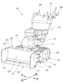
図1は本発明に係る除雪機の斜視図であり、除雪機10は、車体フレーム11と、車体フレーム11の左右に駆動輪12,12(右は図に示していない)及び転輪13,13を介して取付けた左右のクローラベルト14,14と、車体フレーム11に搭載したエンジン15と、車体フレーム11の後側に取付けた操作ハンドル16と、操作ハンドル16の上部に設けた操作盤17と、操作ハンドル16の後端に設けた左右のグリップ部18,18と、車体フレーム11の前側に支持部材21を介して取付けた雪を取り除く除雪板22と、を備えたものである。
【0014】
除雪板22は、除雪板本体23を弓形の断面形状に形成し、この除雪板本体23の左右端部24,25に補強板26,27を取付け、下端にガイド兼隙間塞ぎ材31及びスクレーパ32を取付けたものである。
【0015】
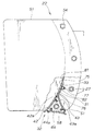
図2は本発明に係る除雪板の斜視図であり、除雪板本体23の左端部24に補強板26を取付け、下端にガイド兼隙間塞ぎ材31及びスクレーパ32を取付けたことを示す。なお、除雪板22は、中心軸線Cに対して左右対称である。
除雪板本体23は、下端に塞ぎ材取付け部33を有する。
【0016】
スクレーパ32は、除雪板22に回転可能に取付けた多角柱材41と、この多角柱材41に取付けた第1刃42,第2刃43,第3刃44と、多角柱材41の回転を阻止する回転止め部材45とで構成したものである。46は、リングである。
【0017】
回転止め部材45は、補強板26に取付ける固定板51と、この固定板51の下部に設けた軸止め部52と、この軸止め部52に通すピン53と、を備えたものである。54・・・(・・・は複数を示す。以下同様。)は、ボルトである。なお、回転止め部材45は、右にも同様に補強板27(図1参照)に取付ける固定板51と、軸止め部52、ピン53、ボルト54・・・を備える。
軸止め部52は、ピン53を止めるためのピン孔55を有する。
【0018】
図3は本発明に係るスクレーパの分解図である。
多角柱材41は、中実の鋼材で、略三角柱の本体56の中央に孔57を形成し、この孔57に支持軸58を溶接で一体的に固定し、外面に第1面61,第2面62,第3面63を所定のアール形状に形成し、各第1,2,3面61,62,63にめねじ64・・・を各々8個形成したものである。65・・・は、ボルトである。
支持軸58は、管の端側に第1角度設定孔66、第2角度設定孔67、第3角度設定孔68(図5参照)を120°のピッチで形成したものである。
【0019】
次にスクレーパ32の刃について説明する。
刃は第1刃42,第2刃43,第3刃44を夫々異種材で構成した。具体的には、第1刃42は、多角柱材41の第1面61に固定する固定部42aと、この固定部42aに開けた8個の取付け孔42b・・・と、先端に形成した刃部71とからなる。第1刃42の材質は、鋼である。
【0020】
第2刃43は、第2面62に固定する固定部43aと、取付け孔43b・・・と、刃部72と、からなる。第2刃43の材質は、樹脂である。
第3刃44は、第3面63に固定する固定部44aと、取付け孔44b・・・と、刃部73と、からなる。第3刃44の材質は、ゴムである。
【0021】
図4は本発明に係る除雪板の側面図であり、一部断面を示し、除雪板22の下端にスクレーパ32を取付け、塞ぎ材取付け部33にガイド兼隙間塞ぎ材31を取付けたことを示す。
【0022】
ガイド兼隙間塞ぎ材31は、塞ぎ材取付け部33に取付ける固定部75と、この固定部75の対向側に形成したシート部76とを有するものである。77はボルトである。
また、ガイド兼隙間塞ぎ材31は、除雪板22の面81に対してガイド兼隙間塞ぎ材31の面82を同一面となるように設定し、且つスクレーパ32の第1刃42の固定部42aにシート部76をほぼ当接させた。なお、シート部76は、第2刃43(固定部43a)及び第3刃44(固定部44a)にも同様にほぼ当接する。
【0023】
以上に述べた除雪機のスクレーパの作用を次に説明する。
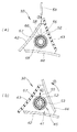
図5(a),(b)は本発明に係るスクレーパの第1作用図である。
(a)において、除雪に使用するスクレーパ32の刃を決める。具体的には、支持軸58に120°のピッチで第1角度設定孔66、第2角度設定孔67、第3角度設定孔68を設け、軸止め部52にピン53を通すとともに、第1角度設定孔66にピン53を通すことで、鋼製の第1刃42が選択された状態になり、第1刃42を使用状態にロックすることができる。
その次に、刃を替える場合は、ピン53を矢印▲2▼の如く引抜くと、ロックが解除されので、スクレーパ32を回転可能状態にすることができる。
【0024】
(b)において、スクレーパ32を図左回転(矢印▲3▼の方向)に所定の角度だけ回転させ、第2角度設定孔67をピン孔55に臨ませ、軸止め部52並びに第2角度設定孔67にピン53を矢印▲4▼の如く嵌め込むと、樹脂製の第2刃43が選択された状態になるとともに、第2刃43を使用状態にロックすることができる。
【0025】
また、第3刃44を選択する場合も、同様にピン53を抜き差しすることで、行うことができる。
このように、多角柱材41に第1,2,3刃42,43,44を取付け、回転止め部材45のピン53を抜くことで、スクレーパ32を回転させて刃を替えることができる。従って、スクレーパ32の刃の交換は容易である。
【0026】
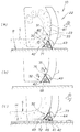
図6(a)〜(c)は本発明に係るスクレーパの第2作用図である。
(a)において、除雪機10を走行(矢印▲5▼の方向)させ、スクレーパ32を路面Rの雪Sに切り込ませて雪Sを削りつつ、除雪を行う。この場合、スクレーパ32は第1刃42を使用し、鋼の刃部71を用いることで、硬い雪を比較的容易に削ることができる。従って、スクレーパ32は硬い雪に対応することができる。
【0027】
また、スクレーパ32にガイド兼隙間塞ぎ材31のシート部76をほぼ当接するように設定し、スクレーパ32と除雪板22との間隙を塞ぐので、スクレーパ32と除雪板本体23側との間に隙間はほとんど発生しない。その結果、除雪板22は雪を後方に漏らすことなく排除することができ、除雪作業の作業効率の向上を図ることができる。同様にガイド兼隙間塞ぎ材31は、第1刃42から第2刃43に替えも、第2刃43にシート部76をほぼ当接する。
【0028】
さらに、除雪板22の下端の塞ぎ材取付け部33にガイド兼隙間塞ぎ材31を取付け、且つ除雪板22の面81に対してガイド兼隙間塞ぎ材31の面82を同一面となるように設定し、ガイド兼隙間塞ぎ材31によってスクレーパ32から除雪板22へ矢印▲6▼の如く移動する雪Sを案内するため、雪Sを滑らかに移動させることができ、除雪性能を向上させることができる。
【0029】
(b)において、スクレーパ32を図左回転(矢印▲3▼の方向)に回転させると、刃は第1刃42から次の第2刃43に替る。その場合、第2刃43はガイド兼隙間塞ぎ材31のシート部76に接触するが、ガイド兼隙間塞ぎ材31は矢印▲7▼の如く揺動すので、スクレーパ32に干渉せず、スクレーパ32の回転を妨げることはない。
【0030】
(c)において、スクレーパ32の刃を第2刃43に替え、樹脂の刃部72を用いて、タイルや木など比較的傷のつきやすい舗装の歩道Hで除雪を実施する。樹脂の刃部72が歩道Hの舗装面に干渉すると、刃部72は弾性変形し、押付け力Fを減衰するので、傷のつきやすい歩道Hの舗装面であっても傷が発生する心配はない。
【0031】
一方、スクレーパ32の刃を第3刃44に設定すると、ゴムの刃部73で比較的硬い雪を削ることができるとともに、削る際の音を低減することができ、早朝や夜間でも迷惑をかけずに除雪作業を行うことができる。
【0032】
このように、多角柱材41に鋼製の第1刃42、樹脂製の第2刃43、ゴム製の第3刃44を取付け、多角柱材41を回転止め部材45で支持したので、地面や雪の状態に合せて、短時間で所望の刃を選択し、使用することができる。その結果、スクレーパ32のみで、硬い雪から軽くて軟らかい雪まで効率よく排除することができるとともに、路面や歩道の舗装面の傷防止を図ることができ、除雪性能の向上を図ることができる。
【0033】
次に、本発明に係るスクレーパの別実施の形態を示す。
図7(a),(b)は別実施の形態図であり、(b)は、(a)の断面図である。上記図2に示す実施の形態と同様の構成については、同一符号を付し説明を省略する。
【0034】
(a)において、スクレーパ32Bは、刃を全数同材質にしたことを特徴とし、具体的には、多角柱材41Bに鋼製の第1刃42,42,42を設けたもので、多角柱材41Bの端面に形成した位置決め穴84((b)参照)と、回転止め部材45Bを有する。
回転止め部材45Bは、固定板51と、この固定板51に取付けた支持部材85と、止めボルト86と、取付けボルト87,87とからなる。
【0035】
(b)において、多角柱材41Bの中央の孔57に支持部材85を嵌め、位置決め穴84に止めボルト86のピン部88を嵌め込み、取付けボルト87を締め付け、除雪板22にスクレーパ32Bを取付けた。
【0036】
このように、別実施の形態では、スクレーパ32Bの刃を3枚共同材質の鋼にしたので、一枚目の第1刃42が変形若しくは破損しても、スクレーパ32Bを回転させて第2面62に取付けた2枚面の第1刃42に替えることができ、取替えに要する時間は極めて短い。従って、短時間で同材質の刃に替えることができ、刃の交換は極めて容易である。
また、回転止め部材45Bはボルトによる締結なので、比較的、雪の抵抗が大きい重い削りに適する。
【0037】
図7の一例では、刃を3枚共同材質の鋼にしたが、3枚の材質を樹脂にしてもよく、ゴムやその他の材質にしてもよい。
また、夫々異種材の刃を取付けた多角柱材41と図7のボルトを用いた回転止め部材45Bとを組合せてもよく、その逆の組合せ(ピン53と同材質を取付けた多角柱材41B)でもよい。
【0038】
尚、本発明の実施の形態に示した図3の多角柱材41の外面(第1面61,第2面62,第3面63)に刃(第1刃42,第2刃43,第3刃44)を取付けたが、多角柱材41の外面に刃を多角柱材41と同材で一体に形成してもよい。
【0039】
多角柱材41は三角柱に限定するものではなく、また、刃(第1刃42,第2刃43,第3刃44)を3枚に限定するものではない。
回転止め部材の構成は任意である。
【0040】
【発明の効果】
本発明は上記構成により次の効果を発揮する。
請求項1では、除雪板の下端に取付けるスクレーパは、除雪板に回転可能に取付けた多角柱材と、この多角柱材の各面に取付ける若しくは形成した刃と、多角柱材の回転を阻止する回転止め部材とで構成し、多角柱材を所定の角度だけ回転させて各面に設けた刃から1個の刃を選択するとともに、雪に臨ませるようにした。雪質、舗装の種類及び刃の状態によって刃を替え、使い分けることができるので、除雪作業を効率的に行うことができるとともに、舗装面に傷をつける心配がない。従って、除雪性能を向上させることができる。
【0041】
また、多角柱材の各面に刃を設け、多角柱材の回転を阻止する回転止め部材を設けたので、回転止め部材で多角柱材を所定の角度だけ回転させて、所望の刃に替えることができる。その結果、その場で短時間で刃を替えることができ、刃の交換は容易である。
【0043】
請求項1では、刃は、夫々異種材で構成したので、雪質や舗装の種類によって使用する刃の材質を替えることができる。例えば、鋼の刃で硬い雪を削り、樹脂の刃で舗装面を傷から守ることができる。
刃を夫々異種材にすることで、材質の異なる刃を短時間で選択することができる。従って、材質が異なる刃に交換するのは容易である。
【0044】
請求項2では、スクレーパと除雪板との間隙を塞ぐとともに、スクレーパから除雪板へ移動する雪を案内するために、除雪板の下端にガイド兼隙間塞ぎ材を取付けたので、除雪する雪がスクレーパと除雪板との境から後方に漏れる心配はなく、仕上りよく除雪することができる。従って、除雪性能を向上させることができる。
また、スクレーパから除雪板へ移動する雪を案内するために、ガイド兼隙間塞ぎ材を取付けたので、雪を滑らかに移動させることができ、除雪性能を向上させることができる。
【図面の簡単な説明】
【図1】本発明に係る除雪機の斜視図
【図2】本発明に係る除雪板の斜視図
【図3】本発明に係るスクレーパの分解図
【図4】本発明に係る除雪板の側面図
【図5】本発明に係るスクレーパの第1作用図
【図6】本発明に係るスクレーパの第2作用図
【図7】別実施の形態図
【符号の説明】
10…除雪機、22…除雪板、31…ガイド兼隙間塞ぎ材、32…スクレーパ、41…多角柱材、42…刃(第1刃)、43…刃(第2刃)、44…刃(第3刃)45,45B…回転止め部材、R…路面、S…雪。[0001]
BACKGROUND OF THE INVENTION
The present invention relates to a scraper for a snowplow.
[0002]
[Prior art]
Examples of the scraper of the snowplow are shown in (1) Japanese Utility Model Publication No. 51-34105 “Snow Removal Case in Snowplow” and (2) Japanese Utility Model Publication No. 52-14347 “Bottom Cutting Blade of Snowplow”. There is something.
According to FIG. 2 of the publication, the technique (1) is the one in which the auxiliary grounding plate 4 is fixed with bolts 5 under the snow removal case 1 (the symbols are those used in the publication; the same shall apply hereinafter). Thus, the auxiliary grounding plate 4 can be adjusted up and down as needed. By lowering, the auger 3 (FIG. 1) is prevented from coming into contact with the ground, and is raised by the auger 3. It is possible to destroy frozen snow and prevent large resistance under the snow removal case 1 beforehand.
[0003]
According to FIG. 2 of the publication, the technique (2) described above is such that the bottom cutting blade 5 is movably attached to the arc-shaped long groove 9 below the auger case 6. Can be moved up or down along 9 and when removing hard snow, the bottom cutting blade 5 is raised above the auger 4 to scrape only with the auger 4 to reduce the propulsion resistance. Can work efficiently.
[0004]
[Problems to be solved by the invention]
The auger can remove hard snow, and if the auger touches the ground such as a road surface or a sidewalk, it may damage the ground. For the purpose of preventing scratches, it is possible to lower the auxiliary ground plate 4 of the above (1) and the bottom cutting blade 5 of the above (2). However, since it is common to use steel plates for the auxiliary ground plate 4 of (1) and the bottom cutting blade 5 of (2), it may still damage the ground. Therefore, the snow removal performance is low.
On the other hand, as a countermeasure against scratches, it is possible to replace the steel plate with a resin plate, but in this case, it is too much labor to remove and attach the auxiliary grounding plate 4 (bottoming blade 5) each time.
[0005]
In the structures {circle around (1)} and {circle around (2)}, the auxiliary grounding plate 4 (bottoming blade 5) violently hits a hard object such as the ground or stone, depending on the level of the auxiliary grounding plate 4 (bottoming blade 5). In some cases, the auxiliary ground plate 4 (bottoming blade 5) may be deformed. In that case, it is extremely difficult to replace the auxiliary ground plate 4 (bottoming blade 5) on the spot. Even if it is exchanged on the spot, it is necessary to prepare things and it takes time and effort to exchange.
[0006]
Therefore, an object of the present invention is to provide a scraper for a snow remover that can improve snow removal performance and can easily replace a blade.
[0007]
[Means for Solving the Problems]
In order to achieve the above object, in claim 1, a scraper attached to a lower end of a snow removal board to scrape snow on a road surface, the scraper is a polygonal pillar member rotatably attached to the snow removal board, and each of the polygonal pillar members. The blade is formed by a blade attached to or formed on a surface and a rotation stopping member for preventing rotation of the polygonal column material, and each of the blades is formed by a different material .
[0008]
A scraper is formed by attaching or forming a blade on each surface of a polygonal column material. The blade is changed depending on the snow quality, the type of pavement, and the state of the blade. As a result, snow removal work can be performed efficiently and the pavement surface can be protected, and the snow removal performance is improved.
In addition, the scraper is provided with a plurality of blades on the polygonal column material, and provided with a rotation preventing member that prevents the rotation of the polygonal column material. The scraper is rotated by a desired angle by rotating the polygonal column material by a desired angle. It can be replaced with a blade. Therefore, it is easy to replace the blade.
[0010]
According to a first aspect of the present invention , the blades are made of different materials.
By using different materials for the blades, the blade material used can be changed depending on the snow quality and the type of pavement. For example, use a steel blade to remove hard snow and a resin blade to protect the pavement from scratches.
By using different types of blades, blades of different materials can be selected in a short time. Therefore, it is easy to replace the blade with a different material.
[0011]
According to a second aspect of the present invention, a guide / gap closing material is attached to the lower end of the snow removing plate in order to close the gap between the scraper and the snow removing plate and guide the snow moving from the scraper to the snow removing plate.
[0012]
The guide / gap closing material was attached to the snow removal board, and the opposite side was applied to the scraper. As a result, the gap between the rotating scraper and the snow removal plate can be closed, and there is no fear that the snow to be removed leaks backward from the boundary between the scraper and the snow removal plate.
Further, when the scraper is rotated, the scraper side of the guide / gap closing material is pushed by the scraper and swings, so that the scraper does not interfere and rotates easily.
Furthermore, since the guide / gap closing material is attached to guide the snow moving from the scraper to the snow removal plate, the snow can be moved smoothly and the snow removal performance is improved.
[0013]
DETAILED DESCRIPTION OF THE INVENTION
Embodiments of the present invention will be described below with reference to the accompanying drawings. The drawings are viewed in the direction of the reference numerals. “Left” and “right” refer to the direction viewed from the operator, “front” refers to the forward side, and “rear” refers to the opposite side.
FIG. 1 is a perspective view of a snowplow according to the present invention. A
[0014]
The
[0015]
FIG. 2 is a perspective view of the snow removal board according to the present invention, showing that the reinforcing
The snow removing
[0016]
The
[0017]
The
The
[0018]
FIG. 3 is an exploded view of the scraper according to the present invention.
The
The
[0019]
Next, the blade of the
As the blades, the
[0020]
The
The
[0021]
FIG. 4 is a side view of the snow removal board according to the present invention, showing a partial cross-section, showing that the
[0022]
The guide /
The guide /
[0023]
Next, the operation of the scraper of the snowplow described above will be described.
5 (a) and 5 (b) are first operational views of the scraper according to the present invention.
In (a), the blade of the
Next, when changing the blade, the
[0024]
In (b), the
[0025]
Also, the
Thus, by attaching the first, second,
[0026]
6 (a) to 6 (c) are second operation views of the scraper according to the present invention.
In (a), the
[0027]
Further, the
[0028]
Further, the guide /
[0029]
In (b), when the
[0030]
In (c), the blades of the
[0031]
On the other hand, when the blade of the
[0032]
In this way, the steel
[0033]
Next, another embodiment of the scraper according to the present invention will be shown.
FIGS. 7A and 7B are diagrams showing another embodiment, and FIG. 7B is a sectional view of FIG. The same components as those in the embodiment shown in FIG.
[0034]
In (a), the
The
[0035]
In (b), the
[0036]
Thus, in another embodiment, since the blades of the
Further, since the
[0037]
In the example of FIG. 7, the three blades are made of joint steel, but the three materials may be resin, rubber, or other materials.
Further, the
[0038]
Note that the outer surfaces (
[0039]
The
The structure of the rotation stop member is arbitrary.
[0040]
【The invention's effect】
The present invention exhibits the following effects by the above configuration.
According to claim 1, the scraper attached to the lower end of the snow removing plate is a polygonal column member rotatably attached to the snow removing plate, a blade attached to or formed on each surface of the polygonal column member, and the rotation of the polygonal column member. The anti-rotation member is configured to rotate the polygonal column material by a predetermined angle to select one blade from the blades provided on each surface and to face the snow. Depending on the snow quality, the type of pavement and the state of the blade, the blades can be changed and used properly, so that snow removal can be performed efficiently and there is no worry of scratching the pavement surface. Therefore, snow removal performance can be improved.
[0041]
In addition, since a blade is provided on each surface of the polygonal column material and a rotation stopping member for preventing the rotation of the polygonal column material is provided, the polygonal column material is rotated by a predetermined angle with the rotation stopping member, and the blade is changed to a desired blade. be able to. As a result, the blade can be changed in a short time on the spot, and the blade can be easily replaced.
[0043]
In claim 1 , since the blades are made of different materials, the blade material used can be changed depending on the snow quality and the type of pavement. For example, hard snow can be shaved with a steel blade, and a paved surface can be protected from scratches with a resin blade.
By using different types of blades, blades of different materials can be selected in a short time. Therefore, it is easy to replace the blade with a different material.
[0044]
According to the second aspect of the present invention , the guide / gap closing material is attached to the lower end of the snow removal plate in order to close the gap between the scraper and the snow removal plate and guide the snow moving from the scraper to the snow removal plate. There is no worry of leaking backward from the border with the snow removal board, and snow can be removed with good finish. Therefore, snow removal performance can be improved.
In addition, since the guide / gap closing material is attached to guide the snow moving from the scraper to the snow removal plate, the snow can be moved smoothly and the snow removal performance can be improved.
[Brief description of the drawings]
1 is a perspective view of a snowplow according to the present invention. FIG. 2 is a perspective view of a snowplow according to the present invention. FIG. 3 is an exploded view of a scraper according to the present invention. FIG. 5 is a first operation diagram of the scraper according to the present invention. FIG. 6 is a second operation diagram of the scraper according to the present invention. FIG. 7 is another embodiment diagram.
DESCRIPTION OF
Claims (2)
前記スクレーパは、除雪板に回転可能に取付けた多角柱材と、この多角柱材の各面に取付ける若しくは形成した刃と、前記多角柱材の回転を阻止する回転止め部材とで構成し、
前記刃は、夫々異種材で構成したことを特徴とする除雪機のスクレーパ。In the scraper attached to the lower end of the snow removal board to remove the snow on the road surface,
The scraper is composed of a polygonal column member that is rotatably attached to a snow removal plate, a blade that is attached to or formed on each surface of the polygonal column member, and a rotation stopping member that prevents rotation of the polygonal column member ,
A scraper of a snowplow , wherein the blades are made of different materials .
Priority Applications (6)
| Application Number | Priority Date | Filing Date | Title |
|---|---|---|---|
| JP2000381434A JP4450401B2 (en) | 2000-12-15 | 2000-12-15 | Snowblower scraper |
| CA002364879A CA2364879C (en) | 2000-12-15 | 2001-12-10 | Scraper for snow removal machine |
| DE60140653T DE60140653D1 (en) | 2000-12-15 | 2001-12-11 | Scraper for a snow removal device |
| EP01129539A EP1215338B1 (en) | 2000-12-15 | 2001-12-11 | Scraper for snow removal machine |
| US10/016,829 US6612050B2 (en) | 2000-12-15 | 2001-12-13 | Scraper for snow removing machine and snow removing attachment having scraper |
| NO20016112A NO335078B1 (en) | 2000-12-15 | 2001-12-14 | Scraper for snow milling machine |
Applications Claiming Priority (1)
| Application Number | Priority Date | Filing Date | Title |
|---|---|---|---|
| JP2000381434A JP4450401B2 (en) | 2000-12-15 | 2000-12-15 | Snowblower scraper |
Publications (2)
| Publication Number | Publication Date |
|---|---|
| JP2002180432A JP2002180432A (en) | 2002-06-26 |
| JP4450401B2 true JP4450401B2 (en) | 2010-04-14 |
Family
ID=18849430
Family Applications (1)
| Application Number | Title | Priority Date | Filing Date |
|---|---|---|---|
| JP2000381434A Expired - Fee Related JP4450401B2 (en) | 2000-12-15 | 2000-12-15 | Snowblower scraper |
Country Status (6)
| Country | Link |
|---|---|
| US (1) | US6612050B2 (en) |
| EP (1) | EP1215338B1 (en) |
| JP (1) | JP4450401B2 (en) |
| CA (1) | CA2364879C (en) |
| DE (1) | DE60140653D1 (en) |
| NO (1) | NO335078B1 (en) |
Cited By (1)
| Publication number | Priority date | Publication date | Assignee | Title |
|---|---|---|---|---|
| KR101249392B1 (en) | 2011-12-19 | 2013-04-03 | 이리중 | Dvice for removing snow for tractor |
Families Citing this family (33)
| Publication number | Priority date | Publication date | Assignee | Title |
|---|---|---|---|---|
| US7676964B2 (en) | 2001-11-12 | 2010-03-16 | Agri-Cover, Inc. | Snow plow having wear minimizing apparatus |
| US7472499B2 (en) * | 2001-11-12 | 2009-01-06 | Agri-Cover, Inc. | Snow plow having pivoting mechanism |
| US7676962B2 (en) | 2001-11-12 | 2010-03-16 | Agri-Cover, Inc. | Snow plow having reinforced mold board |
| US6817118B2 (en) | 2001-11-12 | 2004-11-16 | Charles M. Schmeichel | Self-adjusting snow plow |
| US7676963B2 (en) | 2001-11-12 | 2010-03-16 | Agri-Cover, Inc. | Snow plow including mold board having back plate |
| US7735247B2 (en) | 2001-11-12 | 2010-06-15 | Agri-Cover, Inc. | Snow plow for all terrain vehicle |
| US7784199B2 (en) | 2001-11-12 | 2010-08-31 | Agri-Cover, Inc. | Snow plow having pivotal mounting apparatus |
| US7735245B2 (en) * | 2001-11-12 | 2010-06-15 | Agri-Cover, Inc. | Snow plow having catch structure |
| US7669353B2 (en) | 2001-11-12 | 2010-03-02 | Agri-Cover, Inc. | Snow plow having hitch tongue connecting member |
| US7743534B2 (en) | 2001-11-12 | 2010-06-29 | Agri-Cover, Inc. | Snow plow having two-piece mold board |
| US7707753B2 (en) | 2001-11-12 | 2010-05-04 | Agri-Cover, Inc. | Multifunctional plow blade positioning apparatus and method |
| US8875419B2 (en) | 2001-11-12 | 2014-11-04 | Agri-Cover, Inc. | Snow plow |
| US7681335B2 (en) | 2001-11-12 | 2010-03-23 | Agri-Cover, Inc. | Snow plow having attachable biasing member |
| JP4988203B2 (en) * | 2002-07-19 | 2012-08-01 | インターヴェンショナル スパイン、インコーポレイテッド | Spinal fixation method and spinal fixation device |
| US8037625B2 (en) | 2003-03-31 | 2011-10-18 | Agri-Cover, Inc. | Snow plow having pivotal mounting apparatus |
| US7198687B2 (en) * | 2003-05-01 | 2007-04-03 | Giles A. Hill, III | Squeegee blade |
| US20050178029A1 (en) * | 2003-07-23 | 2005-08-18 | Craig Wightman | Attachment for a plow |
| US20050126051A1 (en) * | 2003-12-16 | 2005-06-16 | Jrb Attachments, Llc | Material pusher with improved structure |
| CA2566993C (en) | 2005-11-03 | 2012-10-02 | Pro-Tech Manufacturing And Distribution, Inc. | Reversible snow pusher and coupler |
| CN101457518A (en) * | 2008-10-21 | 2009-06-17 | 宋树建 | Snow sweeper installed on automobile |
| CA2847402C (en) | 2011-08-31 | 2015-10-27 | Husqvarna Consumer Outdoor Products N.A., Inc. | Trailing shield for a snow removal device |
| US9151006B2 (en) | 2012-02-09 | 2015-10-06 | Pro-Tech Manufacturing And Distribution, Inc. | Material pusher with control system |
| US8955238B1 (en) | 2013-03-06 | 2015-02-17 | John R. Castruccio | Adjustable plow blade |
| US9243376B2 (en) | 2013-06-14 | 2016-01-26 | Pro-Tech Manufacturing And Distribution, Inc. | Surface compliant front-pivoting wear shoes for snow pusher |
| US9938669B2 (en) | 2014-10-16 | 2018-04-10 | Nordco Inc. | Roadworthy rail ballast regulator |
| US10227751B2 (en) * | 2015-01-15 | 2019-03-12 | WJN Enterprises, Inc. | Sectional plow |
| CA2881150C (en) * | 2015-02-04 | 2019-01-15 | David Lorne Stoddart | Snow removal device comprising a pushing element with convex end portions and a scraping flange |
| JP6293705B2 (en) * | 2015-06-03 | 2018-03-14 | 株式会社協和機械製作所 | Cutting edge attachment / detachment mechanism for snow removal equipment |
| US10472783B2 (en) | 2016-03-02 | 2019-11-12 | The Toro Company | Four wheel drive, skid steer snow vehicle with snow plow blade |
| JP6095826B1 (en) * | 2016-04-11 | 2017-03-15 | 株式会社エポック社 | Scraper for weldable bead toy |
| US10422106B2 (en) * | 2017-06-30 | 2019-09-24 | Deere & Company | Removable wiper wall |
| US10895049B2 (en) | 2017-12-11 | 2021-01-19 | Pro-Tech Manufacturing And Distribution, Inc. | Material pusher with modular composite scraping edge |
| US20190330814A1 (en) * | 2018-04-30 | 2019-10-31 | Ozcan Yildiz | Shovel pusher and related systems and methods |
Family Cites Families (8)
| Publication number | Priority date | Publication date | Assignee | Title |
|---|---|---|---|---|
| US3089264A (en) * | 1961-04-20 | 1963-05-14 | Sperry Rand Corp | Trip mechanism for rotary multiple blade scraper |
| DE1929177C3 (en) * | 1969-06-09 | 1978-04-20 | Reissinger, Gottfried, Dr., 8124 St Heinrich | Road clearing device |
| DE2530517A1 (en) | 1974-07-15 | 1976-01-29 | Lummus Co | PROCESS FOR SEPARATION OF TAR AND COAL FROM A BASE MATERIAL CONTAINING CHLORINATED HYDROCARBON |
| JPS5214347A (en) | 1975-07-25 | 1977-02-03 | Hitachi Ltd | Field emission electron gun |
| DE2853126C2 (en) * | 1978-12-08 | 1980-08-21 | Gottfried Dr. Reissinger | Road clearing device |
| US4570366A (en) * | 1984-08-10 | 1986-02-18 | Yost Kenneth J | Snowplow and blade having triangular rotatable cutting block teeth |
| US5611157A (en) * | 1993-10-05 | 1997-03-18 | F & B Enterprises, Inc. | Wear pad assembly |
| US5471770A (en) * | 1993-10-05 | 1995-12-05 | F&B Enterprises, Inc. | Rubberized wear pad assembly and method of making same |
-
2000
- 2000-12-15 JP JP2000381434A patent/JP4450401B2/en not_active Expired - Fee Related
-
2001
- 2001-12-10 CA CA002364879A patent/CA2364879C/en not_active Expired - Fee Related
- 2001-12-11 DE DE60140653T patent/DE60140653D1/en not_active Expired - Lifetime
- 2001-12-11 EP EP01129539A patent/EP1215338B1/en not_active Expired - Lifetime
- 2001-12-13 US US10/016,829 patent/US6612050B2/en not_active Expired - Fee Related
- 2001-12-14 NO NO20016112A patent/NO335078B1/en not_active IP Right Cessation
Cited By (1)
| Publication number | Priority date | Publication date | Assignee | Title |
|---|---|---|---|---|
| KR101249392B1 (en) | 2011-12-19 | 2013-04-03 | 이리중 | Dvice for removing snow for tractor |
Also Published As
| Publication number | Publication date |
|---|---|
| EP1215338A2 (en) | 2002-06-19 |
| CA2364879A1 (en) | 2002-06-15 |
| NO20016112D0 (en) | 2001-12-14 |
| NO335078B1 (en) | 2014-09-08 |
| US6612050B2 (en) | 2003-09-02 |
| JP2002180432A (en) | 2002-06-26 |
| NO20016112L (en) | 2002-06-17 |
| EP1215338A3 (en) | 2003-11-05 |
| CA2364879C (en) | 2006-05-16 |
| US20020073581A1 (en) | 2002-06-20 |
| DE60140653D1 (en) | 2010-01-14 |
| EP1215338B1 (en) | 2009-12-02 |
Similar Documents
| Publication | Publication Date | Title |
|---|---|---|
| JP4450401B2 (en) | Snowblower scraper | |
| US8806784B2 (en) | Trenching system | |
| US8177456B2 (en) | Pavement milling assembly | |
| US20030108414A1 (en) | Tracked compact utility loader | |
| JP2000054315A (en) | Attachment for construction machine and skid-steer loader | |
| CA2080655A1 (en) | Blades for snow-removal vehicles and vehicles therewith | |
| FI121124B (en) | moldboard | |
| GB2152118A (en) | Road surface cutting machines | |
| CA2925911A1 (en) | Folding wing plow | |
| US20050036876A1 (en) | Tracked compact utility loader | |
| CA1061544A (en) | Pavement cutting wheel mounting for earth moving equipment | |
| CA3025237A1 (en) | Folding wing plow | |
| JP2002325502A (en) | Levee reshaping machine | |
| US5333697A (en) | Flip block assembly for changing dozer blade pitch | |
| JP3777233B2 (en) | Self-propelled vibration compaction device | |
| US20050268588A1 (en) | Mower cutting deck having blow-out baffle, and method of using same | |
| KR20090036200A (en) | A device for removing snow | |
| CN219157524U (en) | Snow shovel for forklift | |
| CA2174125A1 (en) | Improvements relating to road cutting apparatus | |
| KR101361480B1 (en) | Snow removal vehicle having shovel pace with rotational guide panel | |
| JP2001271373A (en) | Blade device of civil engineering vehicle | |
| US20200332493A1 (en) | Detachable articulated grading implement for backhoe interchange | |
| AU2009280370A1 (en) | Mouldboard improvements for grading equipment | |
| JP2516045B2 (en) | Road ice cutter | |
| JP3457561B2 (en) | Cutting equipment and cutting machine |
Legal Events
| Date | Code | Title | Description |
|---|---|---|---|
| A621 | Written request for application examination |
Free format text: JAPANESE INTERMEDIATE CODE: A621 Effective date: 20061130 |
|
| A977 | Report on retrieval |
Free format text: JAPANESE INTERMEDIATE CODE: A971007 Effective date: 20090930 |
|
| A131 | Notification of reasons for refusal |
Free format text: JAPANESE INTERMEDIATE CODE: A131 Effective date: 20091013 |
|
| A521 | Request for written amendment filed |
Free format text: JAPANESE INTERMEDIATE CODE: A523 Effective date: 20091211 |
|
| TRDD | Decision of grant or rejection written | ||
| A01 | Written decision to grant a patent or to grant a registration (utility model) |
Free format text: JAPANESE INTERMEDIATE CODE: A01 Effective date: 20100120 |
|
| A01 | Written decision to grant a patent or to grant a registration (utility model) |
Free format text: JAPANESE INTERMEDIATE CODE: A01 |
|
| A61 | First payment of annual fees (during grant procedure) |
Free format text: JAPANESE INTERMEDIATE CODE: A61 Effective date: 20100125 |
|
| R150 | Certificate of patent or registration of utility model |
Free format text: JAPANESE INTERMEDIATE CODE: R150 |
|
| FPAY | Renewal fee payment (event date is renewal date of database) |
Free format text: PAYMENT UNTIL: 20130205 Year of fee payment: 3 |
|
| FPAY | Renewal fee payment (event date is renewal date of database) |
Free format text: PAYMENT UNTIL: 20130205 Year of fee payment: 3 |
|
| FPAY | Renewal fee payment (event date is renewal date of database) |
Free format text: PAYMENT UNTIL: 20140205 Year of fee payment: 4 |
|
| LAPS | Cancellation because of no payment of annual fees |