JP4449149B2 - Air conditioner - Google Patents
Air conditioner Download PDFInfo
- Publication number
- JP4449149B2 JP4449149B2 JP2000086320A JP2000086320A JP4449149B2 JP 4449149 B2 JP4449149 B2 JP 4449149B2 JP 2000086320 A JP2000086320 A JP 2000086320A JP 2000086320 A JP2000086320 A JP 2000086320A JP 4449149 B2 JP4449149 B2 JP 4449149B2
- Authority
- JP
- Japan
- Prior art keywords
- temperature
- set temperature
- time zone
- input
- unit
- Prior art date
- Legal status (The legal status is an assumption and is not a legal conclusion. Google has not performed a legal analysis and makes no representation as to the accuracy of the status listed.)
- Expired - Fee Related
Links
Images


Classifications
-
- G—PHYSICS
- G05—CONTROLLING; REGULATING
- G05D—SYSTEMS FOR CONTROLLING OR REGULATING NON-ELECTRIC VARIABLES
- G05D23/00—Control of temperature
- G05D23/19—Control of temperature characterised by the use of electric means
- G05D23/1902—Control of temperature characterised by the use of electric means characterised by the use of a variable reference value
- G05D23/1904—Control of temperature characterised by the use of electric means characterised by the use of a variable reference value variable in time
-
- F—MECHANICAL ENGINEERING; LIGHTING; HEATING; WEAPONS; BLASTING
- F24—HEATING; RANGES; VENTILATING
- F24F—AIR-CONDITIONING; AIR-HUMIDIFICATION; VENTILATION; USE OF AIR CURRENTS FOR SCREENING
- F24F11/00—Control or safety arrangements
- F24F11/30—Control or safety arrangements for purposes related to the operation of the system, e.g. for safety or monitoring
-
- F—MECHANICAL ENGINEERING; LIGHTING; HEATING; WEAPONS; BLASTING
- F24—HEATING; RANGES; VENTILATING
- F24F—AIR-CONDITIONING; AIR-HUMIDIFICATION; VENTILATION; USE OF AIR CURRENTS FOR SCREENING
- F24F11/00—Control or safety arrangements
- F24F11/62—Control or safety arrangements characterised by the type of control or by internal processing, e.g. using fuzzy logic, adaptive control or estimation of values
- F24F11/63—Electronic processing
- F24F11/64—Electronic processing using pre-stored data
Landscapes
- Engineering & Computer Science (AREA)
- Mechanical Engineering (AREA)
- Signal Processing (AREA)
- Physics & Mathematics (AREA)
- General Engineering & Computer Science (AREA)
- Chemical & Material Sciences (AREA)
- Combustion & Propulsion (AREA)
- Fuzzy Systems (AREA)
- Mathematical Physics (AREA)
- General Physics & Mathematics (AREA)
- Automation & Control Theory (AREA)
- Air Conditioning Control Device (AREA)
- Control Of Temperature (AREA)
Description
【0001】
【発明の属する技術分野】
この発明は、各生活シーンに応じて変化する人体感覚に対して、快適な環境を提供する空気調和装置、及びその制御方法に関する。
【0002】
【従来の技術】
人体の温熱感覚は、温熱環境4要素と呼ばれている温度,湿度,輻射,風速と、人側の要素である着衣量,活動量により決定される。一般に空気調和装置は、温熱環境4要素の内の温度,湿度をコントロールするものであり、これらを一定に制御することを目的にしている。しかし、前述のように人の温熱感覚は人側の要素である着衣量,活動量が影響している。つまり、人は変化する生活の中で暮らしており、変化する生活の中では着衣量,活動量も変わり、これにより人の感覚も変化していると考えられる。活動量は人の歩行,姿勢,動き,作業などにより変化するので、人の行動や生活により快適と感じる環境が変化する。常に快適な環境に制御するには、変化する生活にあった住環境を創造する必要がある。
【0003】
この変化する生活を各シーン毎、例えば睡眠・外出・在宅等のシーン毎に分類すると、その1シーンである睡眠は活動量が激減し、また、着衣量が寝具になっており、在宅等の覚醒時に比べると人側の要素が異なっているので、明らかに快適な環境が異なるといえる。従来、生活シーンに伴なって変化する人体の温熱感覚に対してその時々に快適な住環境を作り出すためには、使用者が空気調和機の設定温度・運転状態をその都度設定変更して使用していた。
【0004】
一方、各生活シーン毎の運転制御では、例えば特開昭62―33239号公報に示されるように、生活シーンの1つである睡眠に対して快適感と省エネルギー性を提供した空気調和装置が開示されている。図14は従来の空気調和装置におけるシフト温度相当電圧のタイミング図である。図において、就寝時におやすみモードスイッチがONされると設定温度シフトを行なうが、この際設定温度のシフト幅と設定温度変更時間(経過時間)を段階的に大きくするような制御を行っている。
【0005】
始めは小さな温度幅でシフトし、段々温度シフト幅を大きくすることで、等間隔に温度をシフトするよりも最終的には同じ回数でより大きくシフト幅を得ることができ、省エネ性が向上する。また、シフト温度を変化させる時間幅をそのシフト温度量に応じて変化させることで就寝時における快適感を損なわないというものであった。
【0006】
また、例えば特開平4―126941号公報に示されるように、睡眠シーンの覚醒時と睡眠時の活動量や着衣量の違いによる温熱感覚の違いに配慮した空気調和装置が開示されている。図15はこの従来の空気調和装置におけるシフト温度のタイミング図である。図において、ユーザーは覚醒時の設定温度とは独立して入床時設定温度と起床時設定温度を任意に入力(設定)でき、起床時には起床時設定温度となるよう起床時刻に向かって自動的に設定温度をシフトして行くというものである。就寝時の快適な設定温度を得るために、入床時の設定温度と起床時の設定温度と起床時刻を任意に設定して覚醒時とは独立した設定温度で快適感を提供することができる。即ち、入床時の設定温度と起床時の設定温度をユーザーが好みに合わせて設定できるため、ユーザーの希望する住環境(睡眠環境)により近く実現できるものである。
【0007】
【発明が解決しようとする課題】
しかしながら、上記のような空気調和装置の構成では、その時々に快適な住環境を作り出すためには、使用者が空気調和機の設定温度等ををその都度設定変更する手間を要するものであった。また、設定変更の手間を省くと快適な住環境を実現できないばかりか省エネ性を考慮せずに運転する場合もあった。
一方、従来例のように各生活シーン毎の運転制御を有する場合でも、その生活シーンの間の設定温度を任意に設定できず、また、設定温度を変化させるパターンが1つしか有していないため必ずしも省エネルギーなものではなかった。
【0008】
本発明はかかる課題を解決するためになされたもので、使用者が望む快適な住環境を24時間操作を簡略化して実現することができ、また、快適な住環境を損なうことなく省エネ性を向上させる空気調和装置を得ることを目的とする。
【0009】
【課題を解決するための手段】
本発明に係わる空気調和装置は、当該空気調和装置の使用者が設定温度の入力を行なう入力部と、室内の空気温度を測定する室内温度検出部と、タイマー機能を有し、現在が1日を所定時間毎に区分した時間帯のどの時間帯にあるかを出力するクロック部と、冷房、暖房の各運転モードに対して、1日を所定時間毎に区分した時間帯毎に設定温度を記憶するとともに、入力部への設定温度の入力があると、クロック部から出力される現在の時間帯と関連付けて、その時間帯の設定温度を、記憶されている設定温度から入力部へ入力された設定温度に変更して記憶する設定温度メモリ部と、少なくとも入力部への設定温度の入力がない場合には、室内温度検出部の検出した室内空気温度が、設定温度メモリ部に記憶されている現在の時間帯の設定温度となるように空調能力制御を行なう空調能力制御部と、冷房、暖房の運転モード毎に、現在の時間帯の設定温度から次の時間帯の設定温度に変更する際の温度変更パターンを複数記憶している温度変更パターンメモリ部と、を備え、空調能力制御部が、温度変更パターンメモリ部に記憶されている温度変更パターンのいずれかにしたがって、現在の時間帯の設定温度から次の時間帯の設定温度に変更するものであって、現在の時間帯の設定温度から次の時間帯の設定温度に変更する際に、運転モードが冷房であれば、現在の時間帯の設定温度より次の時間帯の設定温度が高い冷房温度上昇の場合の方が、現在の時間帯の設定温度より次の時間帯の設定温度が低い冷房温度下降の場合よりも短い時間で設定温度をシフトさせ、運転モードが暖房であれば、現在の時間帯の設定温度より次の時間帯の設定温度が低い暖房温度下降の場合の方が、現在の時間帯の設定温度より次の時間帯の設定温度が高い暖房温度上昇の場合よりも短い時間で設定温度をシフトさせるものである。
【0010】
また、本発明に係わる空気調和装置は、当該空気調和装置の使用者が設定温度の入力を行なう入力部と、室内の空気温度を測定する室内温度検出部と、タイマー機能を有し、現在が1日を所定時間毎に区分した時間帯のどの時間帯にあるかを出力するクロック部と、冷房、暖房の各運転モードに対して、1日を所定時間毎に区分した時間帯毎に設定温度を記憶するとともに、入力部への設定温度の入力があると、クロック部から出力される現在の時間帯と関連付けて、その時間帯の設定温度を、記憶されている設定温度から入力部へ入力された設定温度に変更して記憶する設定温度メモリ部と、少なくとも入力部への設定温度の入力がない場合には、室内温度検出部の検出した室内空気温度が、設定温度メモリ部に記憶されている現在の時間帯の設定温度となるように空調能力制御を行なう空調能力制御部と、冷房、暖房の運転モード毎に、現在の時間帯の設定温度から次の時間帯の設定温度に変更する際の温度変更パターンを複数記憶している温度変更パターンメモリ部と、を備え、空調能力制御部が、温度変更パターンメモリ部に記憶されている温度変更パターンのいずれかにしたがって、現在の時間帯の設定温度から次の時間帯の設定温度に変更するものであって、現在の時間帯の設定温度から次の時間帯の設定温度に変更する際に、運転モードが冷房であれば、現在の時間帯の設定温度より次の時間帯の設定温度が高い冷房温度上昇の場合には、次の時間帯の始まりの時に次の時間帯の設定温度となるように次の時間帯の始まりの時よりも早くから、また現在の時間帯の設定温度より次の時間帯の設定温度が低い冷房温度下降の場合には、次の時間帯の始まりの時から、次の時間帯の設定温度へと向かうように設定温度をシフトさせ、運転モードが暖房であれば、現在の時間帯の設定温度より次の時間帯の設定温度が低い暖房温度下降の場合には、次の時間帯の始まりの時に次の時間帯の設定温度となるように次の時間帯の始まりの時よりも早くから、また現在の時間帯の設定温度より次の時間帯の設定温度が高い暖房温度上昇の場合には、次の時間帯の始まりの時から、次の時間帯の設定温度へと向かうように設定温度をシフトさせるものである。
【0011】
また、本発明に係わる空気調和装置は、設定温度メモリ部が、同一の時間帯内に入力部への設定温度の入力が複数回行なわれた場合には、その時間帯の設定温度を、運転モードが冷房であれば、入力部へ入力された複数の設定温度の内の最高温度に変更して記憶し、運転モードが暖房であれば、入力部へ入力された複数の設定温度の内の最低温度に変更して記憶するものである。
【0020】
【発明の実施の形態】
実施の形態1.
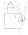
図1は本発明の実施の形態1に係わる空気調和装置の構成図、図2はこの空気調和装置の制御ブロック図、図3は本発明の実施の形態1に係わる空気調和装置の制御フロー図である。
【0021】
図1、2において、1は周波数を一定または可変して運転される圧縮機、2は冷房運転と暖房運転で冷媒の流れる方向を変える四方弁、3は室外側の熱交換器である。この圧縮機1と四方弁2と熱交換器3とが主に室外ユニット4を構成している。
一方、5は室内側の熱交換器、6は室内の空気を循環させる送風機、7は室内から送風機6に空気を吸い込む吸込口、8は送風機6から室内に空気を吹き出す吹出口、9はこの吹出口8に設けられ、送風方向を変更させる風向べーン、10は室内の空気温度を測定する例えばサーミスタ等の室内温度検出部である。この熱交換器5と送風機6と吸込口7と吹出口8と風向べーン9と室内温度検出部10が室内ユニット11を構成している。
【0022】
この室内ユニット4及び室外ユニット11は配管13でそれぞれ接続されており、全体として冷凍サイクルを構成する。従って、圧縮機1の運転及び四方弁2の切り換えで被空調室12の冷房・暖房を行うことができる。また、室内及び室外ユニット4,11は制御信号を送受信するために制御装置14と電気的に接続されている。15は使用者が自分の感覚、望む温度、暖房・冷房などの運転モード等の運転条件を入力するリモコン等の感覚・温度入力部で、使用者の行う入力操作が制御装置14を介して室内外ユニット4,11へ信号という形で送られる。よって、使用者の望む室内の温度設定を満足するように空気調和装置の運転が行われる。ここで、感覚入力とは「暑い」「寒い」等の人体感覚を入力することを意味し、温度入力とは使用者の好みの温度として設定温度を入力することを意味する。
【0023】
また被空調室12の室内空気温度は、室内ユニット11内に設けられた室内温度検出部10で検出されて制御装置14にその信号が送られる。制御装置14はこれらの制御信号を基に空気調和装置の運転を行う。具体的には、空気調和装置の運転に際し、圧縮機1の回転数の変更、室内の送風機6の回転数の変更、風向ベーン9のベーン角度φの変更が、制御装置14からの制御信号を基に随時行われる。
【0024】
ここで、制御装置14について図2を用いて説明する。16はタイマー機能を有し時間の計測を行なうクロック部であり、その計測した時間を設定温度学習部17及び被空調室12の目標温度を決定する目標温度決定部19に出力する。設定温度学習部17は感覚・温度入力部15からの感覚・温度入力とクロック部16からの時間入力から、使用者の入力した設定温度・現在の運転モード・設定温度が入力された時間帯を学習して、設定温度メモリ部18に出力する。18は複数の温度を記憶するメモリを有する設定温度メモリ部で、設定温度学習部17で学習した複数の設定温度を記憶している。例えば1日24時間を1時間づつ区切る場合には、1時間帯毎に学習した設定温度を1日で24個記憶する。また、空気調和装置が冷房・暖房等の運転モードを複数有する場合には、各運転モード毎に24個づつ設定温度を記憶することができる。
【0025】
目標温度決定部19は、使用者が感覚・温度入力部15に温度入力をした場合は、使用者が設定した設定温度等を目標温度と決定する。また、使用者が感覚入力をした場合は、例えば冷房運転時に使用者が「暑い」と入力すれば現在の目標温度―α℃(α=0.5,1.0,1.5)を目標温度と決定する。一方、感覚・温度入力部15からの感覚・温度入力に関わらず、使用者の設定の煩わしさを解消しつつ快適性を向上すべく、1日を所定の時間帯毎に区切ってその区切った各時間帯の始まりの時に(以下本明細書では、「基準時刻」という。)、設定温度メモリ部18に記憶されているその時間帯における学習された設定温度を目標温度として決定する。
【0026】
20は空調能力制御部であり、目標温度決定部19で決定された目標温度と室内温度検出部10で検出した室内空気温度に基づいて、室内空気温度を目標温度にするために、主に圧縮機1の回転数の変更やON/OFF制御を行う。また、能力制御に限定せず、圧縮機1の回転数の変更、室内の送風機6の回転数の変更、風向ベーン9のベーン角度φの変更を随時行うことも可能である。
【0027】
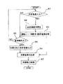
次に、前述の様に構成された実施の形態1における空気調和装置の冷房時の動作について図1〜図3を用いて説明する。図1〜図3において、電源スイッチ(図示せず)をONし、感覚・温度入力部15で使用者が運転モード・設定温度を入力すると(ステップS1のYES)、その情報は制御装置14内の設定温度学習部17に入力される。設定温度学習部17はクロック部16から現在の時間帯の情報を受けとって、その時間帯における運転モード・設定温度を学習して(ステップS2)、設定温度メモリ部18へ出力する。
【0028】
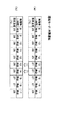
設定温度メモリ部18は、設定温度学習部17からの入力により運転モード・時間帯・学習された設定温度を関連付けて記憶する(ステップS3)。ここで、設定温度メモリ部18に記憶された運転モードが冷房の場合に1時間帯毎に記憶された設定温度を図4に示す。1日24時間を1時間毎に区切った場合、実際の設定温度メモリ部18には設定温度が24個記憶されているが、図4(a)には8時台から17時台までの10個の記憶された設定温度を示す。
【0029】
この設定温度メモリ部18に記憶された設定温度の記憶の書き換え・変更は次の様に行なわれる。13時台の間(所定時間帯)は設定温度メモリ部18に記憶された冷房運転での設定温度は図4(a)のように27℃であるが、13時20分に使用者が感覚・温度入力部15で設定温度26℃の入力を行なった場合、設定温度学習部17はクロック部16からの時間出力によって現在13時台であることより、13時台に入力された設定温度であると判断し、13時台の使用者の快適な温度を学習する。この設定温度を設定温度メモリ部18へ出力して、設定温度メモリ部18は、13時台の設定温度の記憶内容を図4(b)のように27℃から26℃に変更して記憶する。これによって、使用者が入力した設定温度から、使用者の快適な温度を学習するため、生活シーンに対応することができる。
【0030】
また、感覚・温度入力部15で使用者が運転モード・設定温度を入力すると(ステップS1のYES)、使用者の好みの温度に室内温度を変更するため目標温度決定部19はこの入力された設定温度を目標温度に決定する(ステップS4)。一方、感覚・温度入力部15に使用者から設定温度が入力されない場合でも(ステップS1のNO)、目標温度決定部19は随時予め設定された基準時刻か否かをクロック部16からの時間出力から判定する(ステップS5)。
【0031】
基準時刻になっている場合は(ステップS5のYES)、設定温度メモリ部18に記憶されている現在の時間帯の設定温度を読み取って、その設定温度を目標温度に決定する(ステップS4)。この基準時刻は各時間帯の始まりの時刻であり、1時間で区切られている場合は1時、2時、3時という様に設定することもできる。また、基準時刻を各時間帯の始まりに設定せずに、各時間帯の間に設定することもできる。空調能力制御部20は、目標温度決定部19で決定された目標温度と室内温度検出部10で検出した室内空気温度に基づいて、室内空気温度を目標温度にすべく圧縮機1の回転数の変更やON/OFF制御等により、空調能力制御を行なう(ステップS7)。
【0032】
この空調能力制御の状況及び目標温度(設定温度)の変更について以下説明する。図5は室内温度検出部10で検出された室内空気温度の時間推移を示す図である。図5において、○は図4(a)に示す各時間帯(1時間帯)毎に記憶された設定温度を示し、●は感覚・温度入力部15で入力される設定温度を示している。また、実線は目標温度の変化を示し、太線はこれに伴なう室内温度の変化を示す。ここで、感覚・温度入力部15からの入力がない場合には、各時間帯毎に記憶された設定温度を目標温度として、室内空気温度を目標温度となるように空調能力制御が行なわれる。一方、13時20分に感覚・温度入力部15で設定温度26℃が入力されると、目標温度を入力された設定温度(26℃)に変更して空調能力制御が行なわれる。その後、基準時刻である14時になると、目標温度を冷房運転での14時台の記憶された設定温度(27℃)に変更して空調能力制御が行なわれる。
【0033】
本発明の空気調和装置は上述の様に、使用者が空気調和装置の設定温度等をその都度設定変更する手間を省き、1日の内の同時刻での生活シーンは変わらないものと推定して最近の同じ時間帯に入力された設定温度に基づいて目標温度を変更する空調制御を行なうため、その変化する生活に適した快適な住環境を創造することができる。
また、1度使用者が感覚・温度入力手段15で「暑い」という感覚入力や好みの設定温度を入力した場合でも、その後生活シーンが変化すれば使用者の感覚も変化するものと考えられる。しかし、度々設定温度を変更するのは面倒な作業であるため、冷房運転時に少々寒くなっても使用者は設定温度をそのままにしておく場合が多く省エネルギー性の面から好ましくなかったが、基準時刻により学習された設定温度に自動的に変更するため省エネ性を向上させることもできる。即ち、使用者が好みの温度を設定した場合には即応性を維持して快適性を保つとともに、省エネを実現できる点に大きな特徴を有す。
【0034】
また、本実施の形態では、感覚・温度入力部15で設定温度26℃が入力された後、基準時刻になると設定温度に変更して空調能力制御を行なっているが、より使用者の望む温度に設定し快適性を確保するため、感覚・温度入力部15で設定温度が設定された後の所定時間、例えば30分間、クロック部16からの時間出力が基準時刻になっている場合でも、目標温度決定部19は目標温度を設定温度に変更せずに設定温度のままとして空調能力制御を行なうようにすることもできる。
【0035】
実施の形態2.
図6は設定温度メモリ部18に記憶された運転モードが冷房の場合に1時間帯毎に記憶された設定温度を示す図、図7は室内温度検出部10で検出された室内空気温度の時間推移と感覚・温度入力との関係を示す図である。図7において、○は図6(a)に示す所定時間帯(1時間帯)毎における設定温度を示し、●は感覚・温度入力部15で入力される設定温度を示している。なお、空気調和装置の基本的構成は実施の形態1と同様であるので説明は省略する。また、実施の形態1と同一又は相当部分には同じ符号を付し説明を省略する。本実施の形態では、1つの時間帯内に感覚・温度入力部15に2以上の設定温度の入力があった場合に、設定温度学習部17が設定温度の学習をどの様に行なうかについて以下に述べる。
【0036】
1日24時間を1時間毎に区切った場合、実際の設定温度メモリ部18には設定温度が24個記憶されているが、図6(a)には運転モードが冷房の場合に設定温度メモリ部18に記憶された8時台から17時台までの10個の設定温度を示す。感覚・温度入力部15からの入力がない場合でも、目標温度決定部19は実施の形態1で説明したのと同様にクロック部16からの時間出力から基準時刻になっているかを判定し、設定温度メモリ部18に記憶された1時間帯毎の設定温度を目標温度と決定する。
【0037】
従って、室内温度検出部10で検出される室内空気温度は図7に示す様にその時間帯毎の設定温度となるように空調能力の制御を行なう。ここで、感覚・温度入力部15で設定温度が入力された時は、目標温度決定部19は目標温度を設定温度に変更して空調能力の制御を行ない、その後、基準時刻になると目標温度を所定時刻での設定温度に変更して空調能力の制御を行なう。
【0038】
ここで、図7に示す13時台の様に、1時間の間に感覚・温度入力が1回の場合は、設定温度学習部17はクロック部16からの時間出力から現在の時間帯の情報を受けとって、その時間帯における運転モード・設定温度を学習して設定温度メモリ部18へ出力する。一方、14時台の様に、1時間の間に感覚・温度入力が2回以上の場合は、設定温度学習部17は省エネ性を考慮して冷房運転であれば入力された設定温度の内の最高温度と平均温度の間の任意の温度を快適な温度と学習して設定温度メモリ部18へ出力し、暖房運転であれば入力された設定温度の内の最低温度と平均温度の間の任意の温度を快適な温度と学習して設定温度メモリ部18へ出力する。但し、より省エネ要求を満たすために、冷房運転であれば入力された設定温度の内の最高温度を設定温度メモリ部18へ出力し、暖房運転であれば入力された設定温度の内の最低温度を設定温度メモリ部18へ出力することもできる。
【0039】
即ち、使用者による設定温度の入力が14時台のように25℃と26℃の2つがあった場合には、設定温度学習部17は高い方の設定温度である26℃を学習して設定温度メモリ部18へ出力する。設定温度メモリ部18は、14時台の設定温度の記憶内容を図6(b)のように変更して記憶する。上記の様に設定温度を学習する様に設定しても、結局使用者の設定温度に基づいて学習しているため、使用者の快適性を損なわずに省エネ性の向上を図ることができる。また、実施の形態1と同様により最近の使用者の入力動作に基づいて設定温度を記憶することもできる。
【0040】
実施の形態3.
図8は本発明の実施の形態3に係わる空気調和装置の制御ブロック図、図9は基準時刻に対して目標温度へ温度を変更する変更パターン図である。なお、空気調和装置の基本的構成は実施の形態1と同様であるので説明は省略する。また、実施の形態1と同一又は相当部分には同じ符号を付し説明を省略する。実施の形態1ではその時々の生活シーンに合わせた目標温度の決定方法を説明したが、本実施の形態では目標温度へ室内空気温度を変更する変更パターン制御について説明する。
【0041】
図8において、21は複数の温度変更パターンを記憶(メモリ)している温度変更パターンメモリ部である。この温度変更パターンは、冷房・暖房等の各運転モード毎に複数メモリされている。22は室内空気の目標温度及び温度変更パターンを決定する目標温度・変更パターン決定部である。目標温度・変更パターン決定部22は、感覚・温度入力部15からの感覚・温度入力があった場合はその運転モードにおける設定温度を目標温度と決定する。一方、感覚・温度入力部15からの感覚・温度入力がない場合でも、基準時刻になると設定温度メモリ部18に記憶されているその時間帯における設定温度を目標温度として決定する。
【0042】
目標温度・変更パターン決定部22は目標温度を決定すると、次にその目標温度への変更パターンを決定する。即ち、感覚・温度入力部15からの感覚・温度入力があった場合は、使用者が温度変更を望んでいることから、感覚・温度入力時からなるべくすぐに目標温度に変更し、使用者の要求に答える必要がある。一方、設定温度メモリ部18に記憶されているその時間帯における設定温度を目標温度として決定する場合には、使用者からの入力ではないため、できるだけ省エネルギー性を考慮した空調制御を行なう。
【0043】
設定温度メモリ部18に設定温度が1時間帯毎に記憶されている場合、実施の形態1では1時間帯の始まりの時刻である基準時刻にこの設定温度に目標温度を変更する空調能力制御が行なわれたが、本実施の形態ではこの目標温度に対しての温度変更パターンを複数有し、この複数の変更パターンの内何れかに目標温度・変更パターン決定部19で決定して、決定された温度変更パターンに従って目標温度を室内空気温度にすべく圧縮機1の回転数の変更やON/OFF制御を行う。
【0044】
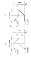
以下に、温度変更パターン及び温度変更パターンの決定方法について述べる。図9(a)に示すように運転パターンが冷房運転の場合、現在の時間帯の設定温度よりも次の時間帯の設定温度の方が高い冷房温度上昇の場合には、基準時刻に次の時間帯の設定温度になる様に早めに目標温度を変更して空調制御を行なう。一方、現在の時間帯の設定温度よりも次の時間帯の設定温度の方が低い冷房温度下降の場合には、基準時刻で目標温度を変更して空調制御を行なう。これによって、冷房運転時にはなるべく高い温度を維持することで、空調負荷の軽減を図るとともに、使用者に冷房の効き過ぎ感を与えずに健康・快適な住環境を提供することができる。
【0045】
また、図9(b)に示すように運転パターンが暖房運転の場合、冷房運転の場合とは逆に、現在の時間帯の設定温度よりも次の時間帯の設定温度の方が高い暖房温度上昇の場合には、基準時刻に目標温度を変更して空調制御を行なう。一方、現在の時間帯の設定温度よりも次の時間帯の設定温度の方が低い暖房温度下降の場合には、基準時刻に次の時間帯の設定温度になる様に早めに目標温度を変更して空調制御を行なう。これによって、暖房運転時にはなるべく低い温度を維持することで、空調負荷の軽減を図ることができる。
【0046】
上記のように、学習された設定温度に基づいて空調制御を行なうことで、使用者の快適性を失うことなく、また、一種類の温度変更パターンしか有していない場合よりも、複数の温度変更パターンを有し、状況に応じて複数の温度変更パターンのうちより省エネ方向の温度変更パターンを選択・決定すれば冷房運転・暖房運転ともにトータル的な負荷を減少させることができ、より省エネ性が向上した運転制御を実現することができる。
【0047】
また、温度変更パターンの他の例を図10に示す。図10(a)に示すように運転パターンが冷房運転の場合、現在の時間帯の設定温度よりも次の時間帯の設定温度の方が高い冷房温度上昇の場合には、基準時刻から素早く目標温度をシフトして空調制御を行なう。一方、現在の時間帯の設定温度よりも次の時間帯の設定温度の方が低い冷房温度下降の場合には、基準時刻からゆっくりと目標温度をシフトする空調制御を行なう。
【0048】
また、図10(b)に示すように運転パターンが暖房運転の場合、冷房運転の場合とは逆に、現在の時間帯の設定温度よりも次の時間帯の設定温度の方が高い暖房温度上昇の場合には、基準時刻からゆっくりと目標温度をシフトして空調制御を行なう。一方、現在の時間帯の設定温度よりも次の時間帯の設定温度の方が低い暖房温度下降の場合には、基準時刻から素早く設定温度になる様に早めに目標温度を変更して温度シフトする空調制御を行なう。上記の様に、目標温度変更パターンの傾きを数種類設けることによっても、冷房運転・暖房運転ともにトータル的な負荷を減少させることができ、より省エネ性が向上する運転制御を実現することができる。
【0049】
更に、目標温度への温度変更時刻に差を設けるとともに、目標温度変更パターンの傾きに差を設けることも可能である。この場合は、冷房運転・暖房運転ともにトータル的な負荷をより減少させることができる。図11にこの運転制御を行なった場合の室内空気温度の時間推移を示す。図11において、12時になると12時台の設定温度である25℃に目標温度を変更してゆっくりと温度シフトを行なう。一方、13時には13時台の設定温度である27℃に室内温度をシフトさせておく方が省エネであるため、12時台から早めに目標温度を変更して空調制御を行なう。更に、13時台・14時台のように感覚・温度入力部15で感覚・温度入力があった場合にはすぐに目標温度を設定温度に変更する。
【0050】
実施の形態4.
図12は本発明の実施の形態4に係わる空気調和装置の制御ブロック図、図13は設定温度メモリ部の記憶内容のイメージ図である。なお、空気調和装置の基本的構成は実施の形態1と同様であるので説明は省略する。また、実施の形態1と同一又は相当部分には同じ符号を付し説明を省略する。
【0051】
人の行動や生活シーンの変化に伴なって快適と感じる環境が変化し、これに対応して常に快適な環境に制御するために、実施の形態1〜3では所定時間帯毎に学習した設定温度に目標温度を決定して空調制御を行ない、変化する生活に適した住環境を創造した。一方、人の生活シーンの内、基本的な生活シーンについては一つの枠組みとして捉えることができる。例えば、睡眠・外出・在宅等の基本的な生活シーンに括ることができ、その生活シーン毎に適した空調制御というものも存在する。
【0052】
例えば、1生活シーンである睡眠は活動量が激減し、また、着衣量が寝具になっており、在宅等の覚醒時に比べると人側の要素が異なっているので、明らかに基本的な快適環境が異なるといえる。本実施の形態では人間の生活シーンの内、基本的な生活シーンについては一つの枠組みとして捉え、各シーン毎に適した空調制御を行なうものついて説明する。
【0053】
図12において、23は感覚及び温度入力手段、運転モードの入力手段、「睡眠モード」・「外出モード」等の各生活シーンに応じた入力手段を有している入力部、24は使用者の基本的な各生活シーンを変更する生活シーン変更部である。ここで、「生活シーン」とは、所定の枠組みで括った睡眠シーン、外出シーン、在宅シーン等を意味している。25は目標温度決定部19の各生活シーンにおける目標温度と室内温度検出部10で検出する室内温度から圧縮機1の回転数の変更、室内の送風機6の回転数の変更、風向ベーン9のベーン角度φを変更を随時行う空調制御部である。
【0054】
また、本実施の形態では実施の形態1〜3で説明した設定温度メモリ部に記憶された設定温度を目標温度に決定して空調制御を行なうものを「基本シーン」として、以下説明する。
生活シーン変更の一例を図13を用いて以下説明する。通常は実施の形態1で説明した様に1時間帯毎の設定温度を目標温度として空調制御を行なう基本シーンであるが、使用者が入力部23に「睡眠モード」を入力した場合には、生活シーン変更部24で睡眠シーン固有の設定温度を記憶している睡眠シーンへと生活シーンを変更し、各生活シーン毎に適した空調制御を行なう。
【0055】
一方、設定温度メモリ部18は各生活シーン毎に固有の設定温度を記憶しており、睡眠シーンにおける設定温度も所定時間帯おきに記憶されている。この所定時間帯は各生活シーン毎に合わせて設定することができ、例えば睡眠シーンであれば、入床時・睡眠時・起床時の3つの時間帯に分けて設定温度を記憶しても良く、また、更に細かく時間帯を設定することもできる。従って、生活シーン変更部24から睡眠シーンへ変更する出力があると、設定温度メモリ部18は生活シーン変更部24を介してクロック部16からの時間出力により、現在の時間帯での睡眠シーン固有に学習した設定温度を目標温度決定部19へ出力する。
【0056】
ここで、目標温度決定部19はその設定温度を目標温度に決定し、空調制御部25は目標温度と室内温度検出部10で検出した室内空気温度に基づいて、先ず、圧縮機1の回転数の変更やON/OFF制御を行う。また、睡眠シーンという固有の生活シーンに適切に対応すべく、睡眠時の空気調和装置の騒音(室内送風機音)による睡眠への悪影響を少なくするため室内の送風機6の回転数を最小に制御する。一方、省エネ運転の要求を満たすために室内熱交換器5の温度と室内空気温度の積算差が所定以上ついた場合には室内の送風機6の回転数をゆっくりと上昇させる。更に、その後は騒音による睡眠への悪影響を考慮して再び室内の送風機6の回転数を最小に制御する。また、眠っている人に直接送風され、過冷感を与えないように睡眠シーンの場合は風向ベーン9のベーン角度φを変更することもできる。
【0057】
また、目標温度決定部19は、睡眠シーンの場合には寝付くまでの所定時間(例えば1〜2時間)は使用者が入力部23に「睡眠モード」を入力した時の設定温度を目標温度とし、所定時間後には睡眠シーンの設定温度を目標温度に切り換えるように設定することもできる。
【0058】
具体的には、図13に示す様に夜の0時に使用者が入床する場合に入力部23で「睡眠モード」が入力された場合、設定温度メモリ部18の記憶内容の読み出しは基本シーンから睡眠シーンへと移って、0時からは睡眠シーンに応じた空調制御を行なう。一方、「睡眠モード」入力時に起床時間を7時に設定した場合には、7時に睡眠シーンから基本生活シーンへと移る。この睡眠シーンの間は上述の様に睡眠シーンに応じた温度制御を行なう。また、睡眠シーンから基本生活シーンへの移行は、「睡眠モード」の解除入力があるまでにして、解除入力があったときに基本生活シーンに移行するようにしても良い。
【0059】
従って、基本的な生活シーンを所定の枠組みとして捉えて各生活シーン毎に適した空調制御が行なわれるとともに、実施の形態1で説明したのと同様に省エネ性を向上することができる。
【0060】
なお、本実施の形態においても、実施の形態3で説明した様に温度変更パターンを複数有しており、各生活シーン毎に応じた変更パターンを選択して快適性・省エネ性を向上させることもできる。
【0061】
【発明の効果】
以上の発明から明らかなように本発明に係わる空気調和装置は、使用者の手間を省いて24時間その時々の生活シーンに応じた使用者が望む快適な住環境を実現することができるとともに、使用者の快適性を損なうことなく、冷房運転・暖房運転ともにトータル的な空調負荷を減少させ、省エネ性が向上する運転制御を実現することができる。
【0071】
また、本発明に係わる空気調和装置の制御方法は、室内温度の温度シフトである温度変更パターンを複数有しているので、温度変更パターンを1つしか有していない場合に較べ制御の自由度が増すため、その時々の生活シーンに応じた使用者が望む快適な住環境を実現でき、また、省エネ性の向上を図ることができる。
【図面の簡単な説明】
【図1】 この発明の実施形態1に係わる空気調和装置の構成図である。
【図2】 この発明の実施形態1に係わる空気調和装置の制御ブロック図である。
【図3】 この発明の実施形態1に係わる空気調和装置の制御フロー図である。
【図4】 この発明の実施形態1に係わる設定温度メモリ部に記憶された設定温度を示す図である。
【図5】 この発明の実施形態1に係わる室内空気温度の時間推移を示す図である。
【図6】 この発明の実施形態2に係わる設定温度メモリ部に記憶された設定温度を示す図である。
【図7】 この発明の実施形態2に係わる室内空気温度の時間推移を示す図である。
【図8】 この発明の実施形態3に係わる空気調和装置の制御ブロック図である。
【図9】 この発明の実施形態3に係わる空気調和装置の温度変更パターンを示す図である。
【図10】 この発明の実施形態3に係わる空気調和装置の温度変更パターンを示す図である。
【図11】 この発明の実施形態3に係わる室内空気温度の時間推移を示す図である。
【図12】 この発明の実施形態4に係わる空気調和装置の制御ブロック図である。
【図13】 この発明の実施形態4に係わる設定温度メモリ部の記憶内容のイメージ図である。
【図14】 従来の空気調和装置におけるシフト温度相当電圧のタイミング図である。
【図15】 従来の空気調和装置におけるシフト温度のタイミング図である。
【符号の説明】
1 圧縮機、 2 四方弁、 3 室外側の熱交換器、 4 室外ユニット、5 室内側の熱交換器、 6 送風機、 7 吸込口、 8 吹出口、 9 風向ベーン、 10 室内温度検出部、 11 室内ユニット、 12 被空調室、 13 配管、 14 制御装置、 15 感覚・温度入力部、 16 クロック部、 17 設定温度学習部、 18 設定温度メモリ部、 19 目標温度決定部、 20 空調能力制御部、 21 温度変更パターン部、 22 目標温度・変更パターン決定部、 23 入力部、 24 生活シーン変更部、25 空調制御部。[0001]
BACKGROUND OF THE INVENTION
The present invention relates to an air conditioner that provides a comfortable environment with respect to human body sensations that change according to each life scene, and a control method thereof.
[0002]
[Prior art]
The thermal sensation of the human body is determined by the temperature, humidity, radiation, and wind speed, which are called the four elements of the thermal environment, and the amount of clothing and activity that are human factors. In general, the air conditioner controls the temperature and humidity of the four elements of the thermal environment, and aims to control them constantly. However, as described above, the amount of clothing and activity, which are factors on the human side, influence the human thermal sensation. In other words, people live in a changing life, and the amount of clothes and activity changes in the changing life, and this is thought to change the human sense. Since the amount of activity changes depending on the person's walking, posture, movement, work, etc., the comfortable environment changes depending on the person's behavior and life. In order to control a comfortable environment at all times, it is necessary to create a living environment suitable for changing lives.
[0003]
If this changing life is classified for each scene, for example, each scene such as sleeping, going out, and at home, the amount of activity is drastically reduced in the sleep that is one scene, and the amount of clothes is bedding. Compared to awakening, human factors are different, so it can be said that the comfortable environment is clearly different. Conventionally, in order to create a comfortable living environment from time to time for the thermal sensation of the human body that changes with the living scene, the user changes the set temperature and operating state of the air conditioner each time and uses it Was.
[0004]
On the other hand, in the driving control for each life scene, for example, as disclosed in Japanese Patent Laid-Open No. 62-33239, an air conditioner that provides comfort and energy saving to sleep, which is one of the life scenes, is disclosed. Has been. FIG. 14 is a timing chart of the shift temperature equivalent voltage in the conventional air conditioner. In the figure, the set temperature shift is performed when the sleep mode switch is turned on at bedtime. At this time, control is performed to increase the set temperature shift width and the set temperature change time (elapsed time) stepwise.
[0005]
By initially shifting with a small temperature range and gradually increasing the temperature shift range, it is possible to finally obtain a larger shift range with the same number of times, rather than shifting the temperature at equal intervals, and energy saving is improved. . Moreover, the comfort range at the time of bedtime is not impaired by changing the time width which changes shift temperature according to the amount of shift temperature.
[0006]
Further, as disclosed in, for example, Japanese Patent Laid-Open No. 4-126941, an air conditioning apparatus is disclosed that takes into account differences in thermal sensation due to differences in the amount of activity and clothes during sleep scene awakening. FIG. 15 is a timing diagram of the shift temperature in this conventional air conditioner. In the figure, the user can arbitrarily input (set) the set temperature at the time of waking up and the set temperature at the time of waking up independently of the set temperature at the time of awakening, and automatically at the time of waking up so as to be the set temperature at the time of waking up The set temperature is shifted to. In order to obtain a comfortable set temperature at bedtime, the set temperature at the time of entry, the set temperature at the time of waking up, and the time of waking up can be arbitrarily set to provide a comfortable feeling at a set temperature independent from that at the time of waking. . That is, since the user can set the set temperature at the time of entering and the set temperature at the time of waking up according to preference, it can be realized closer to the living environment (sleeping environment) desired by the user.
[0007]
[Problems to be solved by the invention]
However, in the configuration of the air conditioner as described above, in order to create a comfortable living environment from time to time, the user needs to change the setting temperature of the air conditioner, etc., each time. . In addition, if the labor of changing the setting is omitted, a comfortable living environment cannot be realized, and there are cases where the vehicle is operated without considering energy saving.
On the other hand, even in the case of having driving control for each life scene as in the conventional example, the set temperature between the life scenes cannot be arbitrarily set, and there is only one pattern for changing the set temperature. Therefore, it was not necessarily energy saving.
[0008]
The present invention has been made to solve such a problem, and can realize a comfortable living environment desired by the user by simplifying the operation for 24 hours, and can save energy without impairing the comfortable living environment. It aims at obtaining the air conditioning apparatus which improves.
[0009]
[Means for Solving the Problems]
The present invention Air conditioner related to Is Concerned Air conditioner users Set up An input unit for inputting a constant temperature; It has an indoor temperature detector that measures the indoor air temperature and a timer function. time Output which time zone of each time zone is divided A clock section; For each of the cooling and heating operation modes, the set temperature is stored for each time zone in which one day is divided every predetermined time, To the input section Set temperature input Is associated with the current time zone output from the clock part, time Obi Set temperature Change from the stored set temperature to the set temperature input to the input section. A preset temperature memory section to store; Air conditioning capability control so that the indoor air temperature detected by the indoor temperature detector becomes the preset temperature for the current time zone stored in the preset temperature memory when at least the preset temperature is not input to the input unit An air-conditioning capacity control unit that performs the operation, and a temperature change pattern memory that stores a plurality of temperature change patterns when changing from the set temperature of the current time zone to the set temperature of the next time zone for each cooling and heating operation mode And With The air conditioning capacity control unit changes from the set temperature of the current time zone to the set temperature of the next time zone according to one of the temperature change patterns stored in the temperature change pattern memory unit, If the operation mode is cooling when changing from the set temperature of the current time zone to the set temperature of the next time zone, if the set temperature of the next time zone is higher than the set temperature of the current time zone If the set temperature is shifted in a shorter time than the cooling temperature drop when the set temperature in the next time zone is lower than the set temperature in the current time zone, and the operation mode is heating, the current time zone When the heating temperature is lower than the set temperature in the next time zone, the set temperature is shorter than when the heating temperature rises when the set temperature in the next time zone is higher than the set temperature in the current time zone. Shift Is.
[0010]
In addition, the present invention Air conditioner related to Is Concerned Air conditioner The user can input the set temperature, the indoor temperature detector for measuring the indoor air temperature, and the timer function, which time zone of the current day is divided into predetermined time intervals A clock section that outputs whether or not Air conditioning ,heating of each operation For each mode, the set temperature is stored for each time zone that is divided into predetermined times per day, and when the set temperature is input to the input unit, it is associated with the current time zone output from the clock unit. , Change the set temperature for that time zone from the stored set temperature to the set temperature input to the input unit and store it Set temperature memory If at least the set temperature is not input to the input unit, air conditioning is performed so that the indoor air temperature detected by the indoor temperature detection unit becomes the set temperature for the current time zone stored in the set temperature memory unit. Air conditioning capability control unit that performs capability control, and temperature change that stores multiple temperature change patterns when changing from the set temperature of the current time zone to the set temperature of the next time zone for each cooling and heating operation mode A pattern memory unit, and the air conditioning capability control unit changes from the set temperature of the current time zone to the set temperature of the next time zone according to any of the temperature change patterns stored in the temperature change pattern memory unit. If the operation mode is cooling when changing from the set temperature in the current time zone to the set temperature in the next time zone, the set temperature in the next time zone from the set temperature in the current time zone. Is cold In the case of a temperature rise, the set time for the next time zone is set at the beginning of the next time zone so that it is earlier than the start time for the next time zone, and the next time from the set temperature for the current time zone. If the set temperature of the belt is low and the cooling temperature is falling, the set temperature is shifted from the beginning of the next time zone to the set temperature of the next time zone, and if the operation mode is heating, In the case of a heating temperature drop that is lower than the set temperature of the current time zone, the start of the next time zone so that the set temperature of the next time zone is reached at the start of the next time zone. If the heating temperature rises earlier than the current time zone, or if the set temperature in the next time zone is higher than the set temperature in the current time zone, the set temperature in the next time zone starts from the beginning of the next time zone. Shift the set temperature so that Is.
[0011]
In addition, the present invention Air conditioner related to Is Set temperature memory But ,Same Within the time zone The set temperature is input to the input section. More than once Done If Is , The operating temperature of the set temperature for that time zone Air conditioning Then, to the input section Entered plural Set temperature Inside Maximum temperature Change to degrees Remember, The operation mode is heating Then, to the input section Entered plural Set temperature Inside Minimum temperature Change to degrees It is something to remember.
[0020]
DETAILED DESCRIPTION OF THE INVENTION
1 is a block diagram of an air conditioner according to
[0021]
1 and 2,
On the other hand, 5 is a heat exchanger on the indoor side, 6 is a blower that circulates indoor air, 7 is a suction port for sucking air into the
[0022]
The indoor unit 4 and the
[0023]
The indoor air temperature in the air-conditioned
[0024]
Here, the
[0025]
When the user inputs a temperature to the sensation /
[0026]
[0027]
Next, the operation | movement at the time of air conditioning of the air conditioning apparatus in
[0028]
The set
[0029]
Rewriting / changing the storage of the set temperature stored in the set
[0030]
Further, when the user inputs the operation mode / set temperature using the sense / temperature input unit 15 (YES in step S1), the target
[0031]
If it is the reference time (YES in step S5), the set temperature of the current time zone stored in the set
[0032]
The air conditioning capability control status and the change of the target temperature (set temperature) will be described below. FIG. 5 is a diagram showing the time transition of the indoor air temperature detected by the
[0033]
As described above, the air conditioner according to the present invention saves the user from having to change the setting temperature of the air conditioner each time and estimates that the life scene at the same time of the day does not change. Since the air conditioning control is performed to change the target temperature based on the set temperature input in the latest recent time period, a comfortable living environment suitable for the changing life can be created.
In addition, even if the user once inputs a sensation of “hot” or a desired set temperature using the sensation / temperature input means 15, the user's sensation is considered to change if the life scene changes thereafter. However, since changing the set temperature frequently is a cumbersome task, users often leave the set temperature as it is even if it gets a little cold during cooling operation, which is not preferable from the viewpoint of energy saving, but it is not preferable for the reference time Since the temperature is automatically changed to the set temperature learned by the above, energy saving can be improved. In other words, when the user sets a desired temperature, there is a great feature in that the quick response is maintained and the comfort is maintained, and the energy saving can be realized.
[0034]
In this embodiment, after the set temperature of 26 ° C. is input by the sensation /
[0035]
FIG. 6 is a diagram showing the set temperature stored for each hour when the operation mode stored in the set
[0036]
When 24 hours a day is divided every hour, 24 set temperatures are stored in the actual set
[0037]
Therefore, the air conditioning capability is controlled so that the indoor air temperature detected by the
[0038]
Here, as in the 13:00 range shown in FIG. 7, when the sensation / temperature input is once in one hour, the set
[0039]
In other words, when there are two input temperatures of 25 ° C. and 26 ° C. as in the 14:00 range, the set
[0040]
FIG. 8 is a control block diagram of the air-conditioning apparatus according to
[0041]
In FIG. 8, reference numeral 21 denotes a temperature change pattern memory unit that stores (memory) a plurality of temperature change patterns. A plurality of temperature change patterns are stored for each operation mode such as cooling and heating.
[0042]
When the target temperature / change
[0043]
When the set temperature is stored in the set
[0044]
Hereinafter, a temperature change pattern and a method for determining the temperature change pattern will be described. As shown in FIG. 9 (a), when the operation pattern is cooling operation, when the set temperature in the next time zone is higher than the set temperature in the current time zone, the cooling time rises at the reference time. Air conditioning control is performed by changing the target temperature as early as possible to reach the set temperature of the time zone. On the other hand, when the cooling temperature is lower than the set temperature of the current time zone, the air temperature control is performed by changing the target temperature at the reference time. As a result, by maintaining as high a temperature as possible during cooling operation, the air conditioning load can be reduced, and a healthy and comfortable living environment can be provided without giving the user a feeling of excessive cooling.
[0045]
In addition, when the operation pattern is the heating operation as shown in FIG. 9B, the heating temperature is higher in the set temperature in the next time zone than the set temperature in the current time zone, contrary to the cooling operation. In the case of an increase, air conditioning control is performed by changing the target temperature at the reference time. On the other hand, if the heating temperature is lower than the set temperature of the current time zone, the target temperature is changed earlier so that the set temperature of the next time zone is reached at the reference time. Air conditioning control is performed. Thereby, the air conditioning load can be reduced by maintaining the lowest possible temperature during the heating operation.
[0046]
As described above, the air conditioning control is performed based on the learned set temperature, so that the user's comfort is not lost, and more than a single temperature change pattern is provided. If there is a change pattern, and the temperature change pattern in the energy saving direction is selected and determined from multiple temperature change patterns according to the situation, the total load can be reduced for both cooling and heating operations, resulting in more energy savings. Can achieve improved operational control.
[0047]
Another example of the temperature change pattern is shown in FIG. When the operation pattern is the cooling operation as shown in FIG. 10A, the target temperature is quickly increased from the reference time when the set temperature in the next time zone is higher than the set temperature in the current time zone. Air conditioning is controlled by shifting the temperature. On the other hand, when the cooling temperature is lower than the preset temperature in the current time zone, the air conditioning control is performed to slowly shift the target temperature from the reference time.
[0048]
In addition, when the operation pattern is the heating operation as shown in FIG. 10B, the heating temperature is higher in the set temperature in the next time zone than the set temperature in the current time zone, contrary to the cooling operation. In the case of an increase, air conditioning control is performed by slowly shifting the target temperature from the reference time. On the other hand, if the set temperature in the next time zone is lower than the set temperature in the current time zone, the target temperature is changed earlier so that the set temperature is quickly reached from the reference time. Air conditioning control is performed. As described above, by providing several types of inclinations of the target temperature change pattern, it is possible to reduce the total load in both the cooling operation and the heating operation, and it is possible to realize operation control that further improves energy saving.
[0049]
Furthermore, it is possible to provide a difference in the temperature change time to the target temperature and to provide a difference in the slope of the target temperature change pattern. In this case, the total load can be further reduced in both the cooling operation and the heating operation. FIG. 11 shows the time transition of the indoor air temperature when this operation control is performed. In FIG. 11, at 12:00, the target temperature is changed to 25 ° C., which is a set temperature in the 12:00 range, and the temperature is slowly shifted. On the other hand, since it is more energy efficient to shift the room temperature to 27 ° C., which is the set temperature at 13:00, at 13:00, air conditioning control is performed by changing the target temperature earlier than 12:00. Further, when there is a sense / temperature input in the sense /
[0050]
Embodiment 4 FIG.
FIG. 12 is a control block diagram of the air-conditioning apparatus according to Embodiment 4 of the present invention, and FIG. 13 is an image diagram of the contents stored in the set temperature memory unit. Note that the basic configuration of the air conditioner is the same as that of the first embodiment, and a description thereof will be omitted. Also, the same or corresponding parts as those in the first embodiment are denoted by the same reference numerals and the description thereof is omitted.
[0051]
In the first to third embodiments, settings learned for each predetermined time period in order to control the environment in which the user feels comfortable according to changes in human behavior and life scene, and to always control the environment to be comfortable. Air conditioning was controlled by determining the target temperature for the temperature, creating a living environment suitable for changing lifestyles. On the other hand, basic life scenes among human life scenes can be regarded as one framework. For example, basic life scenes such as sleeping, going out, and being at home can be summarized, and there is air conditioning control suitable for each life scene.
[0052]
For example, sleep, which is one life scene, has a drastic decrease in activity, and the amount of clothes is bedding, and the elements on the human side are clearly different from those at awakening such as at home. Can be said to be different. In the present embodiment, a basic life scene among human life scenes will be regarded as one frame, and an air conditioning control suitable for each scene will be described.
[0053]
In FIG. 12, reference numeral 23 denotes a sense and temperature input means, an operation mode input means, an input unit having input means corresponding to each life scene such as “sleep mode” and “outing mode”, and 24 denotes a user's It is a life scene changing unit that changes each basic life scene. Here, the “life scene” means a sleep scene, a go-out scene, a home scene, etc., which are bound by a predetermined framework.
[0054]
Further, in the present embodiment, a case where air conditioning control is performed by determining the set temperature stored in the set temperature memory unit described in
An example of a life scene change will be described below with reference to FIG. Normally, as described in the first embodiment, it is a basic scene in which air conditioning control is performed using the set temperature for each hour as a target temperature, but when the user inputs “sleep mode” to the input unit 23, The living
[0055]
On the other hand, the set
[0056]
Here, the target
[0057]
Further, the target
[0058]
Specifically, as shown in FIG. 13, when “sleep mode” is input by the input unit 23 when the user enters the floor at midnight, the stored content of the set
[0059]
Therefore, air conditioning control suitable for each life scene is performed with the basic life scene as a predetermined framework, and energy saving can be improved as described in the first embodiment.
[0060]
In this embodiment as well, as described in the third embodiment, there are a plurality of temperature change patterns, and a change pattern corresponding to each life scene is selected to improve comfort and energy saving. You can also.
[0061]
【The invention's effect】
As is clear from the above invention, the air conditioner according to the present invention is of It is possible to realize a comfortable living environment desired by the user according to the daily life scene, saving time and effort. At the same time, without compromising the user's comfort, it is possible to reduce the total air conditioning load for both cooling and heating operations and realize operation control with improved energy savings. .
[0071]
Moreover, since the control method of the air conditioning apparatus according to the present invention has a plurality of temperature change patterns that are temperature shifts of the room temperature, the degree of freedom of control compared to the case where only one temperature change pattern is provided. Therefore, a comfortable living environment desired by the user according to the daily life scene can be realized, and energy saving can be improved.
[Brief description of the drawings]
FIG. 1 is a configuration diagram of an air-conditioning apparatus according to
FIG. 2 is a control block diagram of the air-conditioning apparatus according to
FIG. 3 is a control flow diagram of the air-conditioning apparatus according to
FIG. 4 is a diagram showing set temperatures stored in a set temperature memory unit according to
FIG. 5 is a diagram showing a time transition of indoor air temperature according to the first embodiment of the present invention.
FIG. 6 is a diagram showing set temperatures stored in a set temperature memory unit according to
FIG. 7 is a diagram showing a time transition of room air temperature according to
FIG. 8 is a control block diagram of an air conditioner according to
FIG. 9 is a view showing a temperature change pattern of the air-conditioning apparatus according to
FIG. 10 is a view showing a temperature change pattern of the air-conditioning apparatus according to
FIG. 11 is a diagram showing a time transition of room air temperature according to
FIG. 12 is a control block diagram of an air-conditioning apparatus according to Embodiment 4 of the present invention.
FIG. 13 is an image view of stored contents of a set temperature memory unit according to Embodiment 4 of the present invention.
FIG. 14 is a timing chart of a shift temperature equivalent voltage in a conventional air conditioner.
FIG. 15 is a timing diagram of shift temperature in a conventional air conditioner.
[Explanation of symbols]
DESCRIPTION OF
Claims (3)
室内の空気温度を測定する室内温度検出部と、
タイマー機能を有し、現在が1日を所定時間毎に区分した時間帯のどの時間帯にあるかを出力するクロック部と、
冷房、暖房の各運転モードに対して、前記1日を所定時間毎に区分した時間帯毎に設定温度を記憶するとともに、前記入力部への設定温度の入力があると、前記クロック部から出力される現在の時間帯と関連付けて、その時間帯の設定温度を、記憶されている設定温度から前記入力部へ入力された設定温度に変更して記憶する設定温度メモリ部と、
少なくとも前記入力部への設定温度の入力がない場合には、前記室内温度検出部の検出した室内空気温度が、前記設定温度メモリ部に記憶されている現在の時間帯の設定温度となるように空調能力制御を行なう空調能力制御部と、
冷房、暖房の運転モード毎に、現在の時間帯の設定温度から次の時間帯の設定温度に変更する際の温度変更パターンを複数記憶している温度変更パターンメモリ部と、を備え、
前記空調能力制御部が、
前記温度変更パターンメモリ部に記憶されている温度変更パターンのいずれかにしたがって、現在の時間帯の設定温度から次の時間帯の設定温度に変更するものであって、
現在の時間帯の設定温度から次の時間帯の設定温度に変更する際に、
前記運転モードが冷房であれば、現在の時間帯の設定温度より次の時間帯の設定温度が高い冷房温度上昇の場合の方が、現在の時間帯の設定温度より次の時間帯の設定温度が低い冷房温度下降の場合よりも短い時間で設定温度をシフトさせ、
前記運転モードが暖房であれば、現在の時間帯の設定温度より次の時間帯の設定温度が低い暖房温度下降の場合の方が、現在の時間帯の設定温度より次の時間帯の設定温度が高い暖房温度上昇の場合よりも短い時間で設定温度をシフトさせるものであることを特徴とする空気調和装置。An input unit that the user of the air conditioner performs an input settings temperature,
An indoor temperature detector for measuring the indoor air temperature;
A clock unit that has a timer function and outputs which time zone of the current time zone is divided into predetermined time intervals ;
For each of the cooling and heating operation modes, the set temperature is stored for each time zone obtained by dividing the day into predetermined time intervals, and when the set temperature is input to the input unit, the clock unit outputs the set temperature. in association with the current time zone to be a setting temperature memory unit that a set temperature of the time zone, and stores the set temperature stored by changing the set temperature inputted to the input unit,
At least when the set temperature is not input to the input unit, the room air temperature detected by the room temperature detecting unit is set to the set temperature of the current time zone stored in the set temperature memory unit. An air conditioning capability control unit for controlling the air conditioning capability;
A temperature change pattern memory unit that stores a plurality of temperature change patterns when changing from the set temperature of the current time zone to the set temperature of the next time zone for each cooling and heating operation mode ,
The air conditioning capability control unit is
According to any one of the temperature change patterns stored in the temperature change pattern memory unit, it is changed from the set temperature of the current time zone to the set temperature of the next time zone,
When changing from the set temperature of the current time zone to the set temperature of the next time zone,
If the operation mode is cooling, the set temperature in the next time zone is higher than the set temperature in the current time zone when the cooling temperature rise is higher than the set temperature in the current time zone. Shift the set temperature in a shorter time than when the cooling temperature drop is low,
If the operation mode is heating, the set temperature in the next time zone is lower than the set temperature in the current time zone when the heating temperature is lower than the set temperature in the current time zone. The air conditioner is characterized in that the set temperature is shifted in a shorter time than in the case of a high heating temperature rise .
室内の空気温度を測定する室内温度検出部と、
タイマー機能を有し、現在が1日を所定時間毎に区分した時間帯のどの時間帯にあるかを出力するクロック部と、
冷房、暖房の各運転モードに対して、前記1日を所定時間毎に区分した時間帯毎に設定温度を記憶するとともに、前記入力部への設定温度の入力があると、前記クロック部から出力される現在の時間帯と関連付けて、その時間帯の設定温度を、記憶されている設定温度から前記入力部へ入力された設定温度に変更して記憶する設定温度メモリ部と、
少なくとも前記入力部への設定温度の入力がない場合には、前記室内温度検出部の検出した室内空気温度が、前記設定温度メモリ部に記憶されている現在の時間帯の設定温度となるように空調能力制御を行なう空調能力制御部と、
冷房、暖房の運転モード毎に、現在の時間帯の設定温度から次の時間帯の設定温度に変更する際の温度変更パターンを複数記憶している温度変更パターンメモリ部と、を備え、
前記空調能力制御部が、
前記温度変更パターンメモリ部に記憶されている温度変更パターンのいずれかにしたがって、現在の時間帯の設定温度から次の時間帯の設定温度に変更するものであって、
現在の時間帯の設定温度から次の時間帯の設定温度に変更する際に、
前記運転モードが冷房であれば、現在の時間帯の設定温度より次の時間帯の設定温度が高い冷房温度上昇の場合には、次の時間帯の始まりの時に次の時間帯の設定温度となるように前記次の時間帯の始まりの時よりも早くから、また現在の時間帯の設定温度より次の時間帯の設定温度が低い冷房温度下降の場合には、次の時間帯の始まりの時から、次の時間帯の設定温度へと向かうように設定温度をシフトさせ、
前記運転モードが暖房であれば、現在の時間帯の設定温度より次の時間帯の設定温度が低い暖房温度下降の場合には、次の時間帯の始まりの時に次の時間帯の設定温度となるように前記次の時間帯の始まりの時よりも早くから、また現在の時間帯の設定温度より次の時間帯の設定温度が高い暖房温度上昇の場合には、次の時間帯の始まりの時から、次の時間帯の設定温度へと向かうように設定温度をシフトさせるものであることを特徴とする空気調和装置。 An input unit that the user of the air conditioner performs an input set temperature,
An indoor temperature detector for measuring the indoor air temperature;
A clock unit that has a timer function and outputs which time zone of the current time zone is divided into predetermined time intervals;
For each of the cooling and heating operation modes , the set temperature is stored for each time zone obtained by dividing the day into predetermined time intervals, and when the set temperature is input to the input unit, the clock unit outputs the set temperature. In association with the current time zone, the set temperature memory unit for storing the set temperature of the time zone is changed from the stored set temperature to the set temperature input to the input unit ,
At least when the set temperature is not input to the input unit, the room air temperature detected by the room temperature detecting unit is set to the set temperature of the current time zone stored in the set temperature memory unit. An air conditioning capability control unit for controlling the air conditioning capability;
A temperature change pattern memory unit that stores a plurality of temperature change patterns when changing from the set temperature of the current time zone to the set temperature of the next time zone for each cooling and heating operation mode,
The air conditioning capability control unit is
According to any one of the temperature change patterns stored in the temperature change pattern memory unit, it is changed from the set temperature of the current time zone to the set temperature of the next time zone,
When changing from the set temperature of the current time zone to the set temperature of the next time zone,
If the operation mode is cooling, in the case of a cooling temperature rise in which the set temperature of the next time zone is higher than the set temperature of the current time zone, the set temperature of the next time zone is set at the beginning of the next time zone. If the cooling temperature is lower than the beginning of the next time zone, or if the set temperature of the next time zone is lower than the set temperature of the current time zone, the time of the start of the next time zone Shift the set temperature so that it goes to the set temperature of the next time zone,
If the operation mode is heating, if the heating temperature is lower than the set temperature of the current time zone, the set temperature of the next time zone is set at the beginning of the next time zone. If the heating temperature rises earlier than the start of the next time zone, or if the set temperature of the next time zone is higher than the set temperature of the current time zone, the time of the start of the next time zone from air-conditioning apparatus, characterized in that in which to shift the set temperature so toward the set temperature of the next time zone.
同一の時間帯内に前記入力部への設定温度の入力が複数回行なわれた場合には、その時間帯の設定温度を、
前記運転モードが冷房であれば、前記入力部へ入力された複数の設定温度の内の最高温度に変更して記憶し、
前記運転モードが暖房であれば、前記入力部へ入力された複数の設定温度の内の最低温度に変更して記憶するものであることを特徴とする請求項1または2に記載の空気調和装置。 The setting temperature memory unit,
When the set temperature is input to the input unit a plurality of times within the same time zone, the set temperature for that time zone is
If the operation mode is cooling, and stores the changed maximum temperature of the plurality of set temperatures input to the input unit,
If the operation mode is the heating, air-conditioning according to claim 1 or 2, characterized in that for storing Change to the top low temperature of the plurality of set temperatures input to the input section apparatus.
Priority Applications (5)
| Application Number | Priority Date | Filing Date | Title |
|---|---|---|---|
| JP2000086320A JP4449149B2 (en) | 2000-03-27 | 2000-03-27 | Air conditioner |
| AU29806/01A AU758760B2 (en) | 2000-03-27 | 2001-03-22 | Air conditioner and method for controlling the same |
| CNB011207744A CN100443815C (en) | 2000-03-27 | 2001-03-26 | Air conditioner and its controlling method |
| US09/816,097 US6540017B2 (en) | 2000-03-27 | 2001-03-26 | Air conditioner and method for controlling the same |
| EP01107527A EP1139035A3 (en) | 2000-03-27 | 2001-03-26 | Air conditioner and method for controlling the same |
Applications Claiming Priority (1)
| Application Number | Priority Date | Filing Date | Title |
|---|---|---|---|
| JP2000086320A JP4449149B2 (en) | 2000-03-27 | 2000-03-27 | Air conditioner |
Publications (3)
| Publication Number | Publication Date |
|---|---|
| JP2001272075A JP2001272075A (en) | 2001-10-05 |
| JP2001272075A5 JP2001272075A5 (en) | 2007-03-15 |
| JP4449149B2 true JP4449149B2 (en) | 2010-04-14 |
Family
ID=18602510
Family Applications (1)
| Application Number | Title | Priority Date | Filing Date |
|---|---|---|---|
| JP2000086320A Expired - Fee Related JP4449149B2 (en) | 2000-03-27 | 2000-03-27 | Air conditioner |
Country Status (5)
| Country | Link |
|---|---|
| US (1) | US6540017B2 (en) |
| EP (1) | EP1139035A3 (en) |
| JP (1) | JP4449149B2 (en) |
| CN (1) | CN100443815C (en) |
| AU (1) | AU758760B2 (en) |
Cited By (1)
| Publication number | Priority date | Publication date | Assignee | Title |
|---|---|---|---|---|
| KR101947557B1 (en) * | 2017-08-25 | 2019-05-08 | 엘지전자 주식회사 | Air conditioner and Method for controlling the same |
Families Citing this family (30)
| Publication number | Priority date | Publication date | Assignee | Title |
|---|---|---|---|---|
| JP2003329285A (en) * | 2002-05-13 | 2003-11-19 | Daikin Ind Ltd | Control device of air conditioner and air conditioner |
| US6968707B2 (en) * | 2003-12-02 | 2005-11-29 | Electrolux Home Products, Inc. | Variable speed, electronically controlled, room air conditioner |
| JP4338604B2 (en) * | 2004-08-02 | 2009-10-07 | 三菱電機株式会社 | Air conditioning control system and remote monitoring device |
| US20070093193A1 (en) * | 2005-10-24 | 2007-04-26 | Cook Lawrence A | Energy efficient paint booth |
| JP2008170080A (en) * | 2007-01-12 | 2008-07-24 | Matsushita Electric Ind Co Ltd | Control method for air conditioner |
| US8154251B2 (en) * | 2007-07-13 | 2012-04-10 | Cummins, Inc. | System and method for controlling vehicle idling and maintaining vehicle electrical system integrity |
| CN101770243B (en) * | 2009-01-06 | 2012-10-31 | 珠海格力电器股份有限公司 | Air conditioning system and dynamic temperature regulating method of air conditioning system |
| JP5804774B2 (en) * | 2011-05-30 | 2015-11-04 | 三菱電機株式会社 | Refrigeration cycle equipment |
| DK2544068T3 (en) * | 2011-07-07 | 2018-12-10 | Danfoss As | Controlled valve assembly for a heat exchanger |
| WO2013058967A1 (en) * | 2011-10-21 | 2013-04-25 | Nest Labs, Inc. | Automated control-schedule acquisition within an intelligent controller |
| JP5871747B2 (en) * | 2012-08-08 | 2016-03-01 | 三菱電機株式会社 | Air conditioner |
| JP5819271B2 (en) * | 2012-09-03 | 2015-11-18 | 日立アプライアンス株式会社 | Air conditioner |
| JP6123331B2 (en) * | 2013-02-13 | 2017-05-10 | 株式会社ソシオネクスト | Device control program, control device system, and device control apparatus |
| US9298197B2 (en) * | 2013-04-19 | 2016-03-29 | Google Inc. | Automated adjustment of an HVAC schedule for resource conservation |
| KR102157072B1 (en) * | 2013-12-03 | 2020-09-17 | 삼성전자 주식회사 | Apparatus and method for controlling a comfort temperature in air conditioning device or system |
| CN103884078A (en) * | 2014-02-28 | 2014-06-25 | 美的集团股份有限公司 | Air conditioner, and control method and control system thereof |
| TWM498082U (en) * | 2014-04-15 | 2015-04-01 | Accutex Technologies Co Ltd | Process liquid cooling system of tool machine |
| CN105134633A (en) * | 2014-05-26 | 2015-12-09 | 珠海格力电器股份有限公司 | Operation control method for electric fan and control system of electric fan |
| US10254726B2 (en) * | 2015-01-30 | 2019-04-09 | Schneider Electric USA, Inc. | Interior comfort HVAC user-feedback control system and apparatus |
| US10571414B2 (en) | 2015-01-30 | 2020-02-25 | Schneider Electric USA, Inc. | Interior volume thermal modeling and control apparatuses, methods and systems |
| US10022023B2 (en) | 2015-04-07 | 2018-07-17 | Vi-Jon, Inc. | Dispenser assembly |
| US10941950B2 (en) | 2016-03-03 | 2021-03-09 | Kabushiki Kaisha Toshiba | Air conditioning control device, air conditioning control method and non-transitory computer readable medium |
| CN106123206B (en) * | 2016-06-17 | 2018-11-23 | 美的集团股份有限公司 | A kind of method and system adjusting ambient heat |
| CN106196485B (en) * | 2016-07-29 | 2018-11-09 | 广东美的制冷设备有限公司 | Temperature control method based on cold and hot inductance value and device |
| KR101954147B1 (en) * | 2016-09-08 | 2019-03-05 | 엘지전자 주식회사 | Air conditioner and Method for controlling the same |
| CN108826595A (en) * | 2018-04-26 | 2018-11-16 | 上海康斐信息技术有限公司 | A kind of control method and system of air purifier |
| CN108870678B (en) * | 2018-06-12 | 2020-04-24 | 珠海格力电器股份有限公司 | Air conditioner control method and air conditioner control device |
| CN109612034B (en) * | 2018-11-30 | 2022-04-12 | 广东美的制冷设备有限公司 | Temperature control method, device and storage medium |
| CN110107998B (en) * | 2019-05-28 | 2021-01-05 | 珠海格力电器股份有限公司 | Energy-saving control method, equipment and medium for multi-connected cold and hot water unit |
| CN110715418B (en) * | 2019-10-29 | 2021-06-18 | 广东美的制冷设备有限公司 | Temperature control method and device for air-conditioning robot |
Family Cites Families (23)
| Publication number | Priority date | Publication date | Assignee | Title |
|---|---|---|---|---|
| US4469274A (en) * | 1980-05-27 | 1984-09-04 | Levine Michael R | Electronic thermostat with repetitive operation cycle |
| US4335847A (en) * | 1980-05-27 | 1982-06-22 | Levine Michael R | Electronic thermostat with repetitive operation cycle |
| US4557317A (en) | 1981-02-20 | 1985-12-10 | Harmon Jr Kermit S | Temperature control systems with programmed dead-band ramp and drift features |
| JPS6233239A (en) | 1985-08-07 | 1987-02-13 | Matsushita Electric Ind Co Ltd | Control system for air conditioner |
| KR900001894B1 (en) * | 1986-09-22 | 1990-03-26 | 미쓰비시덴기 가부시기가이샤 | Air conditioning apparatus |
| JPH01148993A (en) * | 1987-12-07 | 1989-06-12 | Mitsubishi Electric Corp | Timer for controlling air conditioner |
| GB2224863B (en) * | 1988-09-01 | 1992-06-24 | Hunter Melnor Inc | Electronic programmable thermostat for a room air conditioning unit |
| JPH02101344A (en) * | 1988-10-07 | 1990-04-13 | Matsushita Electric Ind Co Ltd | Air conditioner |
| JPH0375435A (en) * | 1989-08-17 | 1991-03-29 | Matsushita Electric Ind Co Ltd | Air conditioner |
| JPH0445341A (en) * | 1990-06-11 | 1992-02-14 | Daikin Ind Ltd | Operation control device for air conditioner device |
| JPH04126941A (en) * | 1990-09-18 | 1992-04-27 | Mitsubishi Electric Corp | Air conditioner |
| JPH04203743A (en) * | 1990-11-29 | 1992-07-24 | Matsushita Electric Ind Co Ltd | Device and method for controlling operation of air-conditioner |
| JP2541016B2 (en) * | 1990-12-14 | 1996-10-09 | 三菱電機株式会社 | Air conditioner |
| JP2973529B2 (en) * | 1991-01-31 | 1999-11-08 | 松下電器産業株式会社 | Air conditioner |
| JP2735395B2 (en) * | 1991-02-14 | 1998-04-02 | 三菱電機株式会社 | Schedule operation device for air conditioner |
| JPH0552379A (en) * | 1991-08-28 | 1993-03-02 | Fujitsu General Ltd | Control of air conditioner |
| JP2768171B2 (en) * | 1992-08-31 | 1998-06-25 | 株式会社トヨトミ | Sleep timer device for air conditioner |
| JPH06159759A (en) * | 1992-11-19 | 1994-06-07 | Matsushita Electric Ind Co Ltd | Bio rhythm set controller |
| JPH10197026A (en) * | 1997-01-14 | 1998-07-31 | Matsushita Refrig Co Ltd | Air conditioner |
| JPH10300164A (en) * | 1997-04-23 | 1998-11-13 | Funai Electric Co Ltd | Air conditioner |
| JP3549710B2 (en) * | 1997-06-25 | 2004-08-04 | 松下電器産業株式会社 | Control device for air conditioner |
| EP0890893A1 (en) | 1997-07-08 | 1999-01-13 | Electrowatt Technology Innovation AG | Regulator for air-conditioned system |
| US5873519A (en) | 1997-08-19 | 1999-02-23 | Heatcraft Inc. | Electronic thermostat with multiple program options |
-
2000
- 2000-03-27 JP JP2000086320A patent/JP4449149B2/en not_active Expired - Fee Related
-
2001
- 2001-03-22 AU AU29806/01A patent/AU758760B2/en not_active Ceased
- 2001-03-26 US US09/816,097 patent/US6540017B2/en not_active Expired - Lifetime
- 2001-03-26 CN CNB011207744A patent/CN100443815C/en not_active Expired - Fee Related
- 2001-03-26 EP EP01107527A patent/EP1139035A3/en not_active Withdrawn
Cited By (1)
| Publication number | Priority date | Publication date | Assignee | Title |
|---|---|---|---|---|
| KR101947557B1 (en) * | 2017-08-25 | 2019-05-08 | 엘지전자 주식회사 | Air conditioner and Method for controlling the same |
Also Published As
| Publication number | Publication date |
|---|---|
| US20010027862A1 (en) | 2001-10-11 |
| US6540017B2 (en) | 2003-04-01 |
| EP1139035A3 (en) | 2002-09-04 |
| CN1321861A (en) | 2001-11-14 |
| CN100443815C (en) | 2008-12-17 |
| EP1139035A2 (en) | 2001-10-04 |
| JP2001272075A (en) | 2001-10-05 |
| AU2980601A (en) | 2001-10-04 |
| AU758760B2 (en) | 2003-03-27 |
Similar Documents
| Publication | Publication Date | Title |
|---|---|---|
| JP4449149B2 (en) | Air conditioner | |
| CN108344126B (en) | Air conditioning system, indoor unit of air conditioning system, and method of controlling the same | |
| JPH116644A (en) | Air conditioning control system | |
| KR910000263B1 (en) | Room air conditioner | |
| JP2000257939A (en) | Air conditioner | |
| JP4476792B2 (en) | Air conditioner | |
| JP2001280663A (en) | Air conditioner and method for controlling it | |
| JPH09303840A (en) | Air conditioner | |
| JP3549401B2 (en) | Operating method of air conditioner | |
| JPH0886486A (en) | Air conditioner | |
| JP4592599B2 (en) | Air conditioner | |
| JP3785866B2 (en) | Air conditioner | |
| JP3070083B2 (en) | Air conditioner | |
| JP3397983B2 (en) | How to control the set temperature of air conditioner remote control | |
| JP2006112700A (en) | Dehumidifying operation control method of air conditioner | |
| JP2003329285A (en) | Control device of air conditioner and air conditioner | |
| JP2611051B2 (en) | Air conditioner | |
| JPH0599472A (en) | Controlling method of air-conditioning machine | |
| JPH09318135A (en) | Air conditioner | |
| JPH04244545A (en) | Air conditioner | |
| JPS61276650A (en) | Air conditioner | |
| JP2737339B2 (en) | Control device for air conditioner | |
| JPH10197026A (en) | Air conditioner | |
| JP2007192479A (en) | Air conditioner | |
| JPH0794909B2 (en) | Air conditioner |
Legal Events
| Date | Code | Title | Description |
|---|---|---|---|
| RD01 | Notification of change of attorney |
Free format text: JAPANESE INTERMEDIATE CODE: A7421 Effective date: 20040722 |
|
| A521 | Request for written amendment filed |
Free format text: JAPANESE INTERMEDIATE CODE: A523 Effective date: 20070129 |
|
| A621 | Written request for application examination |
Free format text: JAPANESE INTERMEDIATE CODE: A621 Effective date: 20070129 |
|
| A977 | Report on retrieval |
Free format text: JAPANESE INTERMEDIATE CODE: A971007 Effective date: 20081226 |
|
| A131 | Notification of reasons for refusal |
Free format text: JAPANESE INTERMEDIATE CODE: A131 Effective date: 20090915 |
|
| A521 | Request for written amendment filed |
Free format text: JAPANESE INTERMEDIATE CODE: A523 Effective date: 20091112 |
|
| TRDD | Decision of grant or rejection written | ||
| A01 | Written decision to grant a patent or to grant a registration (utility model) |
Free format text: JAPANESE INTERMEDIATE CODE: A01 Effective date: 20100105 |
|
| A01 | Written decision to grant a patent or to grant a registration (utility model) |
Free format text: JAPANESE INTERMEDIATE CODE: A01 |
|
| A61 | First payment of annual fees (during grant procedure) |
Free format text: JAPANESE INTERMEDIATE CODE: A61 Effective date: 20100118 |
|
| FPAY | Renewal fee payment (event date is renewal date of database) |
Free format text: PAYMENT UNTIL: 20130205 Year of fee payment: 3 |
|
| FPAY | Renewal fee payment (event date is renewal date of database) |
Free format text: PAYMENT UNTIL: 20130205 Year of fee payment: 3 |
|
| FPAY | Renewal fee payment (event date is renewal date of database) |
Free format text: PAYMENT UNTIL: 20140205 Year of fee payment: 4 |
|
| LAPS | Cancellation because of no payment of annual fees |