JP4445255B2 - Method and apparatus for ultrasonic speckle reduction using broadband frequency synthesis with harmonics generated in tissue - Google Patents
Method and apparatus for ultrasonic speckle reduction using broadband frequency synthesis with harmonics generated in tissue Download PDFInfo
- Publication number
- JP4445255B2 JP4445255B2 JP2003432089A JP2003432089A JP4445255B2 JP 4445255 B2 JP4445255 B2 JP 4445255B2 JP 2003432089 A JP2003432089 A JP 2003432089A JP 2003432089 A JP2003432089 A JP 2003432089A JP 4445255 B2 JP4445255 B2 JP 4445255B2
- Authority
- JP
- Japan
- Prior art keywords
- ultrasonic
- vector
- harmonic
- received signal
- ultrasonic emission
- Prior art date
- Legal status (The legal status is an assumption and is not a legal conclusion. Google has not performed a legal analysis and makes no representation as to the accuracy of the status listed.)
- Expired - Lifetime
Links
- 238000000034 method Methods 0.000 title claims description 24
- 230000015572 biosynthetic process Effects 0.000 title description 16
- 238000003786 synthesis reaction Methods 0.000 title description 16
- 239000013598 vector Substances 0.000 claims description 31
- 230000001427 coherent effect Effects 0.000 claims description 16
- 239000002131 composite material Substances 0.000 claims description 14
- 238000001308 synthesis method Methods 0.000 claims description 9
- 238000002604 ultrasonography Methods 0.000 claims description 9
- 238000012285 ultrasound imaging Methods 0.000 claims description 9
- 238000003384 imaging method Methods 0.000 claims description 7
- 239000000523 sample Substances 0.000 claims description 6
- 238000012805 post-processing Methods 0.000 claims description 3
- 238000010304 firing Methods 0.000 description 20
- 238000010586 diagram Methods 0.000 description 6
- 238000001514 detection method Methods 0.000 description 5
- 238000001228 spectrum Methods 0.000 description 4
- 230000005540 biological transmission Effects 0.000 description 3
- 230000002708 enhancing effect Effects 0.000 description 2
- 239000000284 extract Substances 0.000 description 2
- 238000009499 grossing Methods 0.000 description 2
- 230000005855 radiation Effects 0.000 description 2
- 230000006835 compression Effects 0.000 description 1
- 238000007906 compression Methods 0.000 description 1
- 238000007796 conventional method Methods 0.000 description 1
- 238000002405 diagnostic procedure Methods 0.000 description 1
- 238000002592 echocardiography Methods 0.000 description 1
- 238000001914 filtration Methods 0.000 description 1
- 230000035945 sensitivity Effects 0.000 description 1
- 230000000007 visual effect Effects 0.000 description 1
Images


Classifications
-
- G—PHYSICS
- G01—MEASURING; TESTING
- G01S—RADIO DIRECTION-FINDING; RADIO NAVIGATION; DETERMINING DISTANCE OR VELOCITY BY USE OF RADIO WAVES; LOCATING OR PRESENCE-DETECTING BY USE OF THE REFLECTION OR RERADIATION OF RADIO WAVES; ANALOGOUS ARRANGEMENTS USING OTHER WAVES
- G01S15/00—Systems using the reflection or reradiation of acoustic waves, e.g. sonar systems
- G01S15/88—Sonar systems specially adapted for specific applications
- G01S15/89—Sonar systems specially adapted for specific applications for mapping or imaging
- G01S15/8906—Short-range imaging systems; Acoustic microscope systems using pulse-echo techniques
- G01S15/895—Short-range imaging systems; Acoustic microscope systems using pulse-echo techniques characterised by the transmitted frequency spectrum
-
- G—PHYSICS
- G01—MEASURING; TESTING
- G01S—RADIO DIRECTION-FINDING; RADIO NAVIGATION; DETERMINING DISTANCE OR VELOCITY BY USE OF RADIO WAVES; LOCATING OR PRESENCE-DETECTING BY USE OF THE REFLECTION OR RERADIATION OF RADIO WAVES; ANALOGOUS ARRANGEMENTS USING OTHER WAVES
- G01S7/00—Details of systems according to groups G01S13/00, G01S15/00, G01S17/00
- G01S7/52—Details of systems according to groups G01S13/00, G01S15/00, G01S17/00 of systems according to group G01S15/00
- G01S7/52017—Details of systems according to groups G01S13/00, G01S15/00, G01S17/00 of systems according to group G01S15/00 particularly adapted to short-range imaging
- G01S7/52046—Techniques for image enhancement involving transmitter or receiver
-
- G—PHYSICS
- G06—COMPUTING; CALCULATING OR COUNTING
- G06T—IMAGE DATA PROCESSING OR GENERATION, IN GENERAL
- G06T5/00—Image enhancement or restoration
- G06T5/10—Image enhancement or restoration using non-spatial domain filtering
-
- G—PHYSICS
- G06—COMPUTING; CALCULATING OR COUNTING
- G06T—IMAGE DATA PROCESSING OR GENERATION, IN GENERAL
- G06T5/00—Image enhancement or restoration
- G06T5/70—Denoising; Smoothing
-
- G—PHYSICS
- G06—COMPUTING; CALCULATING OR COUNTING
- G06T—IMAGE DATA PROCESSING OR GENERATION, IN GENERAL
- G06T2207/00—Indexing scheme for image analysis or image enhancement
- G06T2207/10—Image acquisition modality
- G06T2207/10132—Ultrasound image
-
- G—PHYSICS
- G06—COMPUTING; CALCULATING OR COUNTING
- G06T—IMAGE DATA PROCESSING OR GENERATION, IN GENERAL
- G06T2207/00—Indexing scheme for image analysis or image enhancement
- G06T2207/30—Subject of image; Context of image processing
- G06T2207/30004—Biomedical image processing
Landscapes
- Engineering & Computer Science (AREA)
- Physics & Mathematics (AREA)
- General Physics & Mathematics (AREA)
- Radar, Positioning & Navigation (AREA)
- Remote Sensing (AREA)
- Computer Networks & Wireless Communication (AREA)
- Acoustics & Sound (AREA)
- Theoretical Computer Science (AREA)
- Ultra Sonic Daignosis Equipment (AREA)
- Investigating Or Analyzing Materials By The Use Of Ultrasonic Waves (AREA)
Description
本発明は超音波撮像に関し、さらに具体的には、スペックルを低減することにより超音波画像の画質を高める方法及び装置に関する。 The present invention relates to ultrasound imaging, and more specifically to a method and apparatus for enhancing the quality of ultrasound images by reducing speckle.
超音波撮像は、非侵襲的性質であること、比較的低コストであること、及び放射線照射を行なわないことから、多くの診断手順について興味深いモダリティとなっている。医療超音波画像は典型的には、走査線またはベクトルとして知られている既知の方向に走行する超音波を発生して、体内の異なる密度の領域の間の境界で音波が散乱する又は反跳する際に発生するエコーを観測することにより形成される。超音波ビームの任意の所与の方向について、エコーの振幅に比例する輝度を有する点を、測定されている走査線の方向に短い超音波パルスを送波してからの時間の関数となっている位置の座標にプロットすることにより、画像ピクセルが生成される。 Ultrasound imaging is an interesting modality for many diagnostic procedures because of its non-invasive nature, relatively low cost, and lack of radiation. Medical ultrasound images typically generate ultrasound that travels in a known direction known as a scan line or vector, where the sound waves are scattered or recoiled at the boundaries between regions of different density in the body. It is formed by observing the echo generated when For any given direction of the ultrasonic beam, a point having a luminance proportional to the amplitude of the echo is a function of the time since a short ultrasonic pulse was transmitted in the direction of the scan line being measured. Image pixels are generated by plotting the coordinates of the existing location.
コヒーレント放射によって画像を形成する場合に、画像エネルギの所望の分布は望ましくないランダム変調を被る。このランダムなエネルギ分布は「スペックル」として知られており、画像全体に分布するランダムな強度及びランダムな寸法の斑点として視覚画像に現われる。スペックルは、コヒーレント照射された対象によって散乱されたコヒーレント音場のランダムな位相相殺及び位相加算による協調型干渉及び背反型干渉から生ずる。スペックルのパワー・スペクトルは、コヒーレント信号搬送波のスペクトル、音場における散乱体のテクスチャ又は空間分布、照射対象の空間の寸法、並びに受波及び撮像システムの伝達関数に依存する。 When forming an image by coherent radiation, the desired distribution of image energy is subject to undesirable random modulation. This random energy distribution is known as “speckle” and appears in the visual image as spots of random intensity and random dimensions distributed throughout the image. Speckle results from coordinated and anti-coherent interference due to random phase cancellation and phase addition of the coherent sound field scattered by the coherently irradiated object. The speckle power spectrum depends on the spectrum of the coherent signal carrier, the texture or spatial distribution of the scatterers in the sound field, the size of the space to be illuminated, and the transfer function of the receiving and imaging system.
ランダムな組織散乱によって超音波画像に発生されるスペックルは、微細な組織構造を不明瞭にして画像コントラストを低下させる場合がある。周波数合成は、スペックルを低減し、延いてはコントラスト分解能を高める周知の方法である。周波数合成においては、異なる周波数特性を有する画像をインコヒーレント加算する。本発明者等の経験によれば、スペックル低減のための既存の周波数合成法では、検出された狭帯域信号の加算に起因する分解能低下が生ずる。これらの狭帯域信号は典型的には、受波時の狭帯域濾波によって得られる。従って、高分解能合成の方法及び装置が必要とされている。 Speckle generated in an ultrasound image by random tissue scattering may obscure the fine tissue structure and reduce image contrast. Frequency synthesis is a well-known method of reducing speckle and thus increasing contrast resolution. In frequency synthesis, images having different frequency characteristics are added incoherently. According to the experience of the present inventors, in the existing frequency synthesis method for speckle reduction, the resolution is reduced due to the addition of detected narrowband signals. These narrowband signals are typically obtained by narrowband filtering during reception. Accordingly, there is a need for a high resolution synthesis method and apparatus.
一般的には、本発明の目的は、改良された超音波撮像方法及び装置を提供することにある。 In general, it is an object of the present invention to provide an improved ultrasonic imaging method and apparatus.
本発明のもう一つの目的は、微細な構造を不明瞭にして画像コントラストを低下させるスペックルの量を減少させつつ組織の識別を可能にする改良された超音波撮像方法及び装置を提供することにある。本発明のさらにもう一つの目的は、組織で発生される高調波との広帯域周波数合成を用いたかかる方法及び装置を提供することにある。本発明の以上の目的及びその他の目的は、当業者には以下の発明の詳細な説明及び添付図面から明らかとなろう。 Another object of the present invention is to provide an improved ultrasound imaging method and apparatus that allows tissue identification while reducing the amount of speckle that obscures the fine structure and reduces image contrast. It is in. Yet another object of the present invention is to provide such a method and apparatus using broadband frequency synthesis with harmonics generated in tissue. These and other objects of the present invention will become apparent to those skilled in the art from the following detailed description of the invention and the accompanying drawings.
本発明は、超音波画像においてスペックル・パターンを平滑化し、且つコントラスト分解能を高める方法及び装置である。他の周波数合成手法と比較すると、広帯域高調波周波数合成は、分解能を犠牲にせずにスペックル雑音を低減する。空間合成と比較すると、広帯域高調波周波数合成は、合成のために連続フレームではなく連続ベクトルを加算するため、組織の運動に対する堅牢性が高い。本発明の方法及び装置は、2以上の発射(ファイアリング、firing)を送波し、これらの発射の2以上をコヒーレント結合して組織で発生される高調波成分を抽出し、コヒーレント和の出力を検出すると共にコヒーレント和の前の1以上の発射を検出して、最後に、検出した全ての出力を結合して合成画像を形成することにより具現化される。 The present invention is a method and apparatus for smoothing speckle patterns and enhancing contrast resolution in ultrasound images. Compared to other frequency synthesis techniques, wideband harmonic frequency synthesis reduces speckle noise without sacrificing resolution. Compared to spatial synthesis, broadband harmonic frequency synthesis is more robust to tissue motion because it adds continuous vectors rather than continuous frames for synthesis. The method and apparatus of the present invention transmits two or more shots (firing), extracts the harmonic components generated in the tissue by coherently combining two or more of these shots, and outputs a coherent sum. And one or more firings prior to the coherent sum are detected, and finally all detected outputs are combined to form a composite image.
本発明の方法及び装置は、広帯域基本波画像と広帯域高調波画像とを検出後に加算して合成画像を形成する。他の周波数合成法と異なり、送波信号及び受波信号は共に広帯域であり、狭帯域フィルタは不要である。2以上の異なる送波波形での多重発射が各々の焦点ゾーンへ送波される。 The method and apparatus of the present invention add a broadband fundamental image and a broadband harmonic image after detection to form a composite image. Unlike other frequency synthesis methods, both the transmitted signal and the received signal have a wide band, and a narrow band filter is unnecessary. Multiple launches with two or more different transmit waveforms are transmitted to each focal zone.
一般的には、超音波ビームは、トランスデューサのアレイを用いて該アレイに関して所与の方向に送波ビームを形成することにより発生される。超音波パルスは、所定の周波数にある振幅変調パルスであり、包絡線関数によって指定される振幅を有する。このパルスによって発生するエコーは、同じ又は異なるトランスデューサのアレイによって検出され、このアレイを用いて送波ビームに対応する受波ビームを形成する。マイクロホンすなわち超音波プローブの感度は指向性を有するので、音響パルスの多重反射によって発生されるエコーは減少する。 In general, an ultrasonic beam is generated by using an array of transducers to form a transmit beam in a given direction with respect to the array. An ultrasonic pulse is an amplitude modulated pulse at a predetermined frequency and has an amplitude specified by an envelope function. The echo generated by this pulse is detected by the same or different array of transducers and is used to form a received beam corresponding to the transmitted beam. Since the sensitivity of the microphone or ultrasonic probe is directional, echoes generated by multiple reflections of acoustic pulses are reduced.
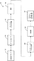
超音波撮像は一般的には、幾つかの本質的な構成要素を用いたシステムによって達成される。図1は、本発明の方法による超音波イメージング・システムのブロック図であり、超音波イメージング・システムが参照番号10として全体的に示されている。システム10は、超音波プローブ12、ビームフォーマ14、コヒーレント・ベクトル加算手段16、検出手段18、インコヒーレント・ベクトル加算手段20、後処理手段22、並びにスキャン・コンバータ及び表示手段24を含んでいる。一般的には、超音波プローブ12を走査対象に位置合わせして、操作者がスキャン・コンバータ及び表示手段24を用いて、プローブ12によって検出される走査結果を視覚化して観察する。
Ultrasound imaging is generally accomplished by a system that uses several essential components. FIG. 1 is a block diagram of an ultrasound imaging system according to the method of the present invention, the ultrasound imaging system being generally designated as
本発明は、広帯域基本波画像と広帯域高調波画像とを検出後に加算して合成画像を形成する。他の周波数合成法と異なり、送波信号及び受波信号は共に広帯域であり、狭帯域フィルタは不要である。2以上の異なる送波波形での多重発射が各々の焦点ゾーンへ送波される。 The present invention adds a broadband fundamental wave image and a broadband harmonic image after detection to form a composite image. Unlike other frequency synthesis methods, both the transmitted signal and the received signal have a wide band, and a narrow band filter is unnecessary. Multiple launches with two or more different transmit waveforms are transmitted to each focal zone.
本発明の方法及び装置は、異なるスペックル・パターンを有する複数の広帯域画像を合成して、分解能の損失なしにスペックルを抑制することを教示する。このことは、図2及び図3に示すように、2以上の発射を送波し、これらの発射の2以上をコヒーレント結合して組織で発生される高調波成分を抽出し、コヒーレント加算の出力を検出すると共にコヒーレント和の前の1以上の発射を検出して、最後に、検出した全ての出力を結合して合成画像を形成することにより具現化される。 The method and apparatus of the present invention teaches combining multiple broadband images with different speckle patterns to suppress speckle without loss of resolution. This means that, as shown in FIGS. 2 and 3, two or more shots are transmitted, two or more of these shots are coherently combined to extract harmonic components generated in the tissue, and the output of the coherent addition And one or more firings prior to the coherent sum are detected, and finally all detected outputs are combined to form a composite image.
図2〜図5を参照すると、ビームフォーマ36、38及び88によってそれぞれ発生される送波波形62、64及び110は、基本周波数f0の近くのピーク・パワー・レベルによって特徴付けられることが分かる。ビームフォーマ90及び92によってそれぞれ発生される送波波形112及び114は、もう一つの基本周波数f1の近くのピーク・パワー・レベルによって特徴付けられる。ビームフォーマによって発生される超音波エコー情報には、基本周波数における情報と、高調波周波数において非線形的に生成される情報とが含まれる。ビームフォーマによって受波されるエコー情報は、送波周波数における情報を実質的に除去することにより高調波周波数情報を分離する他の従来の方法のような濾波は施されていない。一実施形態では、2f0での広帯域高調波画像をf0及び2f0での広帯域基本波画像とインコヒーレント加算して、最終合成画像を形成する。各々の焦点ゾーンに2回又は3回の発射を行なってよい。
Referring to FIGS. 2-5, it can be seen that the transmit
図2及び図4には、参照番号30として全体的に示す2回発射構成が概略図示されている。2回発射構成30では、周波数f0での2回の発射32及び34の広帯域送波波形62及び64は同じ振幅であるが反対の位相を有する。換言すると、この状態はc(t)=−b(t)によって表わされる。一方の発射62の受波信号66が検出され(ブロック48)、やはりf0にある広帯域基本波ベクトルを形成する。2回発射32及び34の受波信号66及び68は等しい加重すなわちGain2=Gain3(参照番号42及び44)を施されて加算され(ブロック46)、検出されて(ブロック50)、2f0にある広帯域高調波ベクトル70を形成する。次いで、2つのベクトル66及び70が加算されて(ブロック52)、合成画像72を形成する。加重Gain1(参照番号40)は、基本波画像及び高調波画像のスペックルが近似的に同じ輝度を有するような何らかの値に設定される。
2 and 4 schematically illustrate a two-fire configuration generally designated as
また、図3及び図5に示すように、参照番号80として全体的に示す3回発射構成では、送波波形a(t)110での1回目の発射82を用いて広帯域基本波ベクトル116を形成する。同じ振幅及び反対の位相を有する送波波形b(t)112及びc(t)114での残り2回の発射84及び86を結合して(ブロック100)、広帯域高調波ベクトル122を形成する。送波波形a(t)110は、b(t)112及びc(t)114と異なっている。次いで、2つのベクトル116及び122を加算して(ブロック106)、合成画像124を形成する。この構成80におけるゲイン設定94、96及び98は、2回発射30の場合と同じである。2回発射構成30は相対的に高いフレーム・レートを与え、3回発射構成80は、基本波画像及び高調波画像の両方について最適化された品質を保証する。
Also, as shown in FIGS. 3 and 5, in the three-shot configuration generally indicated by
他の実施形態では、同じ位相であるが異なる振幅を有する2つの広帯域波形を発射することにより広帯域高調波画像を得る。次いで、2回の発射をGain3=−Gain2/βでコヒーレント加算して、基本波成分を相殺すると共に高調波成分を抽出する。上述と同様の2回発射設定又は3回発射設定をこの実施形態でも利用することができる。 In other embodiments, a broadband harmonic image is obtained by firing two broadband waveforms having the same phase but different amplitudes. Next, two launches are coherently added with Gain3 = −Gain2 / β to cancel out the fundamental wave component and extract the harmonic component. A two-shot setting or a three-shot setting similar to that described above can also be used in this embodiment.
さらに他の実施形態では、基本波ベクトルと高調波ベクトルとの加算に先立って、検出及び対数圧縮を実行する。この実施形態は、検出されたベクトル同士を合成のために乗算することと等価である。 In yet another embodiment, detection and logarithmic compression are performed prior to the addition of the fundamental vector and the harmonic vector. This embodiment is equivalent to multiplying the detected vectors for synthesis.
尚、以上の実施形態は、他の多重発射と広帯域合成との組み合わせに拡張し得ることも理解されたい。このことを一般的に表現すると、先ず、2回以上の超音波発射を行なう。これらの発射を幾つかのグループに分割する。これにより、各々のグループが他のグループと発射を共有することができる。発射が1回よりも多いグループでは、発射をコヒーレント結合して組織で発生される高調波成分を形成する。高調波成分には、低調波、超高調波、二次高調波又は高次高調波が含まれ得る。発射が1回よりも多いグループの数は1以上であってよい。発射が1回のグループの数も1以上であってよい。各々のグループについて、2回以上の発射の場合はコヒーレント和の出力が検出され、1回の発射の場合は発射が直接的に検出される。検出された全ての出力を結合して、前述のような合成画像を形成する。 It should be understood that the above embodiments can be extended to other combinations of multiple launches and broadband synthesis. To express this generally, first, two or more ultrasonic waves are emitted. Divide these launches into groups. This allows each group to share launches with other groups. For groups with more than one firing, the firings are coherently combined to form harmonic components generated in the tissue. The harmonic components can include subharmonics, superharmonics, second harmonics, or higher harmonics. The number of groups with more than one firing may be one or more. The number of groups fired at one time may also be one or more. For each group, the output of the coherent sum is detected for more than one firing, and the firing is directly detected for one firing. All detected outputs are combined to form a composite image as described above.
従って、本発明は、超音波画像のスペックル・パターンを平滑化し、且つコントラスト分解能を高める方法及び装置であることが理解されよう。他の周波数合成手法と比較すると、広帯域高調波周波数合成は、分解能を犠牲にせずにスペックル雑音を低減する。空間合成と比較すると、広帯域高調波周波数合成は、合成のために連続フレームではなく連続ベクトルを加算するため、組織の運動に対する堅牢性が高い。本発明の方法及び装置は、2回以上の発射を送波し、これらの発射の2以上をコヒーレント結合して組織で発生される高調波成分を抽出し、コヒーレント和の出力を検出すると共にコヒーレント和の前の1以上の発射を検出して、最後に、検出した全ての出力を結合して合成画像を形成することにより具現化される。 Accordingly, it will be appreciated that the present invention is a method and apparatus for smoothing speckle patterns in ultrasound images and increasing contrast resolution. Compared to other frequency synthesis techniques, wideband harmonic frequency synthesis reduces speckle noise without sacrificing resolution. Compared to spatial synthesis, broadband harmonic frequency synthesis is more robust to tissue motion because it adds continuous vectors rather than continuous frames for synthesis. The method and apparatus of the present invention transmits two or more shots, and coherently combines two or more of these shots to extract the harmonic components generated in the tissue, detects the output of the coherent sum, and coherently. It is embodied by detecting one or more firings before the sum and finally combining all detected outputs to form a composite image.
本発明の方法及び装置は、広帯域基本波画像と広帯域高調波画像とを検出後に加算して合成画像を形成する。他の周波数合成法と異なり、送波信号及び受波信号は共に広帯域であり、狭帯域フィルタは不要である。2以上の異なる送波波形での多重発射が各々の焦点ゾーンへ送波される。以上の記載は、本発明の方法を限定するのではなく例示するものとする。本発明の範囲は、特許請求の範囲によって定義されるものとする。 The method and apparatus of the present invention add a broadband fundamental image and a broadband harmonic image after detection to form a composite image. Unlike other frequency synthesis methods, both the transmitted signal and the received signal have a wide band, and a narrow band filter is unnecessary. Multiple launches with two or more different transmit waveforms are transmitted to each focal zone. The above description is intended to illustrate rather than limit the method of the present invention. The scope of the present invention shall be defined by the claims.
10 超音波イメージング・システム
30 2回発射構成
62、64 2回発射の送波波形
66、68 受波信号
70、122 広帯域高調波ベクトル
72、124 合成画像
80 3回発射構成
110、112、114 3回発射の送波波形
116、118、120 受波信号
10
Claims (6)
(a)前記コヒーレント・ベクトル加算手段(16)が基本周波数にある第1の波形を含んでいる第1の超音波発射に対する第1の受波信号(66)と、基本周波数にある第2の波形を含んでいる第2の超音波発射に対する第2の受波信号(68)とをコヒーレント・ベクトル加算して、高調波ベクトル(70)を形成する工程と、
(b)前記インコヒーレント加算手段(20)が前記第1の受波信号(66)と、前記高調波ベクトル(70)とを周波数合成法を使用したインコヒーレント加算して、合成画像(72)を形成する工程と、
を備えた方法。 An ultrasound imaging system comprising coherent vector addition means (16) and incoherent addition means (20) is a method for forming an ultrasound image comprising:
(A) the first received signal (66) for the first ultrasonic emission, wherein the coherent vector adding means (16) includes a first waveform at the fundamental frequency, and a second at the fundamental frequency. Coherently adding a second received signal (68) to a second ultrasonic emission containing a waveform to form a harmonic vector (70);
(B) The incoherent addition means (20) performs incoherent addition using the frequency synthesis method on the first received signal (66) and the harmonic vector (70) to obtain a composite image (72). Forming a step;
With a method.
(a)前記コヒーレント・ベクトル加算手段(16)が基本周波数にある第1の波形を含んでいる第1の超音波発射に対する第1の受波信号(118)と、第1の超音波と同じ振幅及び反対の位相を有する第2の超音波発射に対する第2の受波信号(120)とをコヒーレント・ベクトル加算して、高調波ベクトル(122)を形成する工程と、
(b)前記インコヒーレント加算手段(20)が基本周波数にある第2の波形を含んでいる第3の超音波発射に対する第3の受波信号(116)と、前記高調波ベクトル(122)とを周波数合成法を使用したインコヒーレント加算して、合成画像(124)を形成する工程と、
を備えた方法。 An ultrasound imaging system comprising coherent vector addition means (16) and incoherent addition means (20) is a method for forming an ultrasound image comprising:
(A) the first received signal (118) for the first ultrasonic emission including the first waveform at which the coherent vector adding means (16) is at the fundamental frequency, and the same as the first ultrasonic wave Coherently adding a second received signal (120) for a second ultrasonic emission having an amplitude and opposite phase to form a harmonic vector (122);
(B) a third received signal (116) for a third ultrasonic emission in which the incoherent addition means (20) includes a second waveform at a fundamental frequency; and the harmonic vector (122); Incoherent addition using a frequency synthesis method to form a composite image (124);
With a method.
(a)超音波プローブと、
(b)基本周波数にある第1の波形を含んでいる第1の超音波発射と、基本周波数にある第2の波形を含んでいる第2の超音波発射を行うビームフォーマと、
(c)前記第1の超音波発射に対する第1の受波信号(66)と、前記第2の超音波発射に対する第2の受波信号(68)とをコヒーレント・ベクトル加算して、高調波ベクトル(70)を形成する手段と
(d)前記第1の受波信号(66)と、前記高調波ベクトル(70)とを周波数合成法を使用したインコヒーレント加算して、合成画像(72)を形成する手段と、
(e)後処理手段と、
(f)スペックルが抑制された画像を表示するスキャン・コンバータ及び表示手段と、
を備えた超音波撮像装置。 An ultrasonic imaging device comprising:
(A) an ultrasonic probe;
(B) a beamformer that performs a first ultrasonic emission that includes a first waveform at a fundamental frequency and a second ultrasonic emission that includes a second waveform at a fundamental frequency;
(C) Coherent vector addition of the first received signal (66) for the first ultrasonic emission and the second received signal (68) for the second ultrasonic emission to generate a harmonic A means for forming a vector (70); and (d) an incoherent addition of the first received signal (66) and the harmonic vector (70) using a frequency synthesis method to obtain a composite image (72). Means for forming
(E) post-processing means;
(F) a scan converter and a display means for displaying an image in which speckle is suppressed;
An ultrasonic imaging apparatus comprising:
(a)超音波プローブと、
(b)基本周波数にある第1の波形を含んでいる第1の超音波発射と、第1の超音波と同じ振幅及び反対の位相を有する第2の超音波発射と、基本周波数にある第2の波形を含んでいる第3の超音波発射とを行うビームフォーマと、
(c)前記第1の超音波発射に対する第1の受波信号(118)と、前記第2の超音波発射に対する第2の受波信号(120)とをコヒーレント・ベクトル加算して、高調波ベクトル(122)を形成する手段と、
(d)前記第3の超音波発射に対する第3の受波信号(116)と、前記高調波ベクトル(122)とを周波数合成法を使用したインコヒーレント加算して、合成画像(72)を形成する手段と、
(e)後処理手段と、
(f)スペックルが抑制された画像を表示するスキャン・コンバータ及び表示手段と、
を備えた超音波撮像装置。
An ultrasonic imaging device comprising:
(A) an ultrasonic probe;
(B) a first ultrasonic emission including a first waveform at a fundamental frequency, a second ultrasonic emission having the same amplitude and opposite phase as the first ultrasonic wave, and a first ultrasonic emission at the fundamental frequency. A beamformer for performing a third ultrasonic emission including two waveforms;
(C) Coherent vector addition of the first received signal (118) for the first ultrasonic emission and the second received signal (120) for the second ultrasonic emission to generate a harmonic Means for forming a vector (122);
(D) A third received signal (116) for the third ultrasonic emission and the harmonic vector (122) are incoherently added using a frequency synthesis method to form a synthesized image (72). Means to
(E) post-processing means;
(F) a scan converter and a display means for displaying an image in which speckle is suppressed;
An ultrasonic imaging apparatus comprising:
Applications Claiming Priority (1)
| Application Number | Priority Date | Filing Date | Title |
|---|---|---|---|
| US10/335,277 US6827685B2 (en) | 2002-12-31 | 2002-12-31 | Method of ultrasonic speckle reduction using wide-band frequency compounding with tissue-generated harmonics |
Publications (3)
| Publication Number | Publication Date |
|---|---|
| JP2004209246A JP2004209246A (en) | 2004-07-29 |
| JP2004209246A5 JP2004209246A5 (en) | 2007-02-15 |
| JP4445255B2 true JP4445255B2 (en) | 2010-04-07 |
Family
ID=32655307
Family Applications (1)
| Application Number | Title | Priority Date | Filing Date |
|---|---|---|---|
| JP2003432089A Expired - Lifetime JP4445255B2 (en) | 2002-12-31 | 2003-12-26 | Method and apparatus for ultrasonic speckle reduction using broadband frequency synthesis with harmonics generated in tissue |
Country Status (2)
| Country | Link |
|---|---|
| US (1) | US6827685B2 (en) |
| JP (1) | JP4445255B2 (en) |
Families Citing this family (8)
| Publication number | Priority date | Publication date | Assignee | Title |
|---|---|---|---|---|
| JP5154554B2 (en) | 2006-08-01 | 2013-02-27 | ボストン サイエンティフィック サイムド,インコーポレイテッド | Pulse inversion sequence for nonlinear imaging |
| GB2461710A (en) * | 2008-07-09 | 2010-01-13 | Newcastle Upon Tyne Hospitals | Multi-frequency ultrasound imaging |
| JP5322522B2 (en) * | 2008-07-11 | 2013-10-23 | 株式会社東芝 | Ultrasonic diagnostic equipment |
| JP5469983B2 (en) * | 2009-10-02 | 2014-04-16 | ジーイー・メディカル・システムズ・グローバル・テクノロジー・カンパニー・エルエルシー | Ultrasonic diagnostic apparatus and control program therefor |
| EP2385391A3 (en) | 2010-05-04 | 2012-08-01 | Sony Corporation | Active imaging device and method for speckle noise reduction |
| KR20140040679A (en) * | 2010-11-15 | 2014-04-03 | 인디언 인스티튜트 오브 테크놀로지 카라그푸르 | An improved ultrasound imaging method/technique for speckle reduction/suppression in an improved ultra sound imaging system |
| WO2014147517A1 (en) * | 2013-03-20 | 2014-09-25 | Koninklijke Philips N.V. | Beamforming techniques for ultrasound microcalcification detection |
| US10905401B2 (en) * | 2017-07-09 | 2021-02-02 | The Board Of Trustees Of The Leland Stanford Junior University | Ultrasound imaging with spectral compounding for speckle reduction |
Family Cites Families (10)
| Publication number | Priority date | Publication date | Assignee | Title |
|---|---|---|---|---|
| US4561019A (en) | 1983-05-16 | 1985-12-24 | Riverside Research Institute | Frequency diversity for image enhancement |
| JPH0751270A (en) * | 1993-08-13 | 1995-02-28 | Hitachi Medical Corp | Ultrasonic diagnostic device |
| US5793701A (en) * | 1995-04-07 | 1998-08-11 | Acuson Corporation | Method and apparatus for coherent image formation |
| US5623928A (en) * | 1994-08-05 | 1997-04-29 | Acuson Corporation | Method and apparatus for coherent image formation |
| US6050942A (en) * | 1997-07-11 | 2000-04-18 | Atl Ultrasound | Digital scanline signal processor for an ultrasonic diagnostic imaging system |
| US6071240A (en) * | 1997-09-22 | 2000-06-06 | General Electric Company | Method and apparatus for coherence imaging |
| US5957852A (en) | 1998-06-02 | 1999-09-28 | Acuson Corporation | Ultrasonic harmonic imaging system and method |
| JP2001061841A (en) * | 1999-08-30 | 2001-03-13 | Toshiba Corp | Ultrasonograph, and method of producing ultrasonic image |
| JP3688561B2 (en) * | 2000-06-30 | 2005-08-31 | アロカ株式会社 | Ultrasonic diagnostic equipment |
| JP4723747B2 (en) * | 2001-04-09 | 2011-07-13 | 株式会社東芝 | Ultrasonic diagnostic equipment |
-
2002
- 2002-12-31 US US10/335,277 patent/US6827685B2/en not_active Expired - Lifetime
-
2003
- 2003-12-26 JP JP2003432089A patent/JP4445255B2/en not_active Expired - Lifetime
Also Published As
| Publication number | Publication date |
|---|---|
| JP2004209246A (en) | 2004-07-29 |
| US6827685B2 (en) | 2004-12-07 |
| US20040127795A1 (en) | 2004-07-01 |
Similar Documents
| Publication | Publication Date | Title |
|---|---|---|
| JP4433427B2 (en) | System and method for imaging ultrasound scatterers | |
| JP4150866B2 (en) | Method of operating an ultrasound imaging system | |
| US6827686B2 (en) | System and method for improved harmonic imaging | |
| US6969353B2 (en) | Contrast-agent enhanced color-flow imaging | |
| US7874988B2 (en) | Ultrasonic diagnostic apparatus and ultrasonic transmission method | |
| JP4570116B2 (en) | Harmonic imaging method and apparatus using multiple focal zones | |
| JP4022393B2 (en) | Ultrasonic diagnostic equipment | |
| JP6978316B2 (en) | Broadband mixed fundamental and harmonic frequency ultrasound diagnostic imaging | |
| JP4931910B2 (en) | Ultrasonic imaging device | |
| JP2009505771A (en) | Ultrasound imaging system and method for flow imaging with real-time space synthesis | |
| US6960169B2 (en) | Spread spectrum coding for ultrasound contrast agent imaging | |
| JP4642977B2 (en) | Ultrasonic diagnostic apparatus and ultrasonic imaging method | |
| JP2004508087A (en) | Ultrasound diagnostic image processing system and method utilizing harmonic spatial synthesis | |
| JP4405182B2 (en) | Ultrasonic diagnostic equipment | |
| JP2004121848A (en) | System and method for performing continuous depth harmonic imaging using transmitted and nonlinearly generated secondary harmonic | |
| JP4445255B2 (en) | Method and apparatus for ultrasonic speckle reduction using broadband frequency synthesis with harmonics generated in tissue | |
| JP4458407B2 (en) | Harmonic imaging method and apparatus using multiplex transmission | |
| WO2019208767A1 (en) | Ultrasound system and ultrasound system control method | |
| Demi et al. | Orthogonal frequency division multiplexing combined with multi line transmission for ultrafast ultrasound imaging: Experimental findings | |
| CN113768542B (en) | Ultrasonic blood flow imaging device and ultrasonic equipment | |
| KR102452220B1 (en) | Imaging method, apparatus implementing the method, a computer program and a computer-readable storage medium | |
| JP3519882B2 (en) | Ultrasound imaging device | |
| Schou et al. | Synthetic aperture sequential beamforming using spatial matched filtering | |
| US11129598B2 (en) | Calibration for ARFI imaging | |
| JP4580490B2 (en) | Ultrasonic diagnostic equipment |
Legal Events
| Date | Code | Title | Description |
|---|---|---|---|
| A521 | Request for written amendment filed |
Free format text: JAPANESE INTERMEDIATE CODE: A523 Effective date: 20061221 |
|
| A621 | Written request for application examination |
Free format text: JAPANESE INTERMEDIATE CODE: A621 Effective date: 20061221 |
|
| A871 | Explanation of circumstances concerning accelerated examination |
Free format text: JAPANESE INTERMEDIATE CODE: A871 Effective date: 20061221 |
|
| A975 | Report on accelerated examination |
Free format text: JAPANESE INTERMEDIATE CODE: A971005 Effective date: 20070115 |
|
| A131 | Notification of reasons for refusal |
Free format text: JAPANESE INTERMEDIATE CODE: A131 Effective date: 20070130 |
|
| A521 | Request for written amendment filed |
Free format text: JAPANESE INTERMEDIATE CODE: A523 Effective date: 20070209 |
|
| A131 | Notification of reasons for refusal |
Free format text: JAPANESE INTERMEDIATE CODE: A131 Effective date: 20070410 |
|
| A521 | Request for written amendment filed |
Free format text: JAPANESE INTERMEDIATE CODE: A523 Effective date: 20070420 |
|
| A02 | Decision of refusal |
Free format text: JAPANESE INTERMEDIATE CODE: A02 Effective date: 20070724 |
|
| A521 | Request for written amendment filed |
Free format text: JAPANESE INTERMEDIATE CODE: A523 Effective date: 20071018 |
|
| A911 | Transfer to examiner for re-examination before appeal (zenchi) |
Free format text: JAPANESE INTERMEDIATE CODE: A911 Effective date: 20071129 |
|
| A912 | Re-examination (zenchi) completed and case transferred to appeal board |
Free format text: JAPANESE INTERMEDIATE CODE: A912 Effective date: 20071221 |
|
| A601 | Written request for extension of time |
Free format text: JAPANESE INTERMEDIATE CODE: A601 Effective date: 20090206 |
|
| A602 | Written permission of extension of time |
Free format text: JAPANESE INTERMEDIATE CODE: A602 Effective date: 20090213 |
|
| A521 | Request for written amendment filed |
Free format text: JAPANESE INTERMEDIATE CODE: A523 Effective date: 20091126 |
|
| RD02 | Notification of acceptance of power of attorney |
Free format text: JAPANESE INTERMEDIATE CODE: A7422 Effective date: 20091126 |
|
| RD04 | Notification of resignation of power of attorney |
Free format text: JAPANESE INTERMEDIATE CODE: A7424 Effective date: 20091126 |
|
| A01 | Written decision to grant a patent or to grant a registration (utility model) |
Free format text: JAPANESE INTERMEDIATE CODE: A01 |
|
| A61 | First payment of annual fees (during grant procedure) |
Free format text: JAPANESE INTERMEDIATE CODE: A61 Effective date: 20100115 |
|
| R150 | Certificate of patent or registration of utility model |
Ref document number: 4445255 Country of ref document: JP Free format text: JAPANESE INTERMEDIATE CODE: R150 Free format text: JAPANESE INTERMEDIATE CODE: R150 |
|
| FPAY | Renewal fee payment (event date is renewal date of database) |
Free format text: PAYMENT UNTIL: 20130122 Year of fee payment: 3 |
|
| R250 | Receipt of annual fees |
Free format text: JAPANESE INTERMEDIATE CODE: R250 |
|
| R250 | Receipt of annual fees |
Free format text: JAPANESE INTERMEDIATE CODE: R250 |
|
| R250 | Receipt of annual fees |
Free format text: JAPANESE INTERMEDIATE CODE: R250 |
|
| R250 | Receipt of annual fees |
Free format text: JAPANESE INTERMEDIATE CODE: R250 |
|
| R250 | Receipt of annual fees |
Free format text: JAPANESE INTERMEDIATE CODE: R250 |
|
| R250 | Receipt of annual fees |
Free format text: JAPANESE INTERMEDIATE CODE: R250 |
|
| R250 | Receipt of annual fees |
Free format text: JAPANESE INTERMEDIATE CODE: R250 |
|
| R250 | Receipt of annual fees |
Free format text: JAPANESE INTERMEDIATE CODE: R250 |
|
| R250 | Receipt of annual fees |
Free format text: JAPANESE INTERMEDIATE CODE: R250 |
|
| R250 | Receipt of annual fees |
Free format text: JAPANESE INTERMEDIATE CODE: R250 |
|
| R250 | Receipt of annual fees |
Free format text: JAPANESE INTERMEDIATE CODE: R250 |
|
| EXPY | Cancellation because of completion of term |