JP4438199B2 - Start-up control method for portable electronic device and portable electronic device - Google Patents
Start-up control method for portable electronic device and portable electronic device Download PDFInfo
- Publication number
- JP4438199B2 JP4438199B2 JP2000265549A JP2000265549A JP4438199B2 JP 4438199 B2 JP4438199 B2 JP 4438199B2 JP 2000265549 A JP2000265549 A JP 2000265549A JP 2000265549 A JP2000265549 A JP 2000265549A JP 4438199 B2 JP4438199 B2 JP 4438199B2
- Authority
- JP
- Japan
- Prior art keywords
- docking station
- identification information
- electronic key
- portable electronic
- electronic device
- Prior art date
- Legal status (The legal status is an assumption and is not a legal conclusion. Google has not performed a legal analysis and makes no representation as to the accuracy of the status listed.)
- Expired - Fee Related
Links
Images


Landscapes
- Lock And Its Accessories (AREA)
Description
【0001】
【発明の属する技術分野】
本発明は単体でも使用可能な携帯型電子機器をドッキングステーションと接続して使用する場合の携帯型電子機器の起動制御方法および携帯型電子機器に関する。
【0002】
【従来の技術】
従来から、ノートパソコンやPDA(Personal Digital Assistant)などと呼ばれる情報処理用の携帯型電子機器は、単体で使用することも可能であると同時に、ドッキングステーションと呼ばれる拡張ユニットと組合せての使用が可能にされている場合がある。たとえば特開2000−112580号公報には、ノートパソコン、すなわちノートブック型のパーソナルコンピュータを機能拡張のためのドッキングステーションである拡張ユニットに装着すると、パーソナルコンピュータを自動的にパワーオンさせることができるコンピュータシステムについての先行技術が開示されている。この先行技術のドッキングステーションは、LAN(Local Area Network)への接続を可能にするために設けられる。一般にドッキングステーションは、携帯型電子機器が携帯性を重視するために、充分なハードウエアを搭載することができない点を補うために用いられる。したがって、ドッキングステーションは、直接大容量の記憶装置が接続されていたり、LANを通じて大容量の記憶装置に接続されていたりすることが多い。そのような記憶装置には、重要な情報が記憶され、正当な権限を有しない者が情報を読出したり情報を改変したりすることを防がなければならない。
【0003】
一般に重要な業務などに用いるコンピュータ装置では、情報へのアクセスを正当な権限を有する者に限るために、セキュリティの確保が図られている。たとえばコンピュータ装置の使用を開始するにあたって行うログオン手続きで、操作者の資格を識別情報であるIDを入力させて確認したり、パスワードを入力させて確認するようにしている。さらに一層確実なセキュリティの確保のために、電子鍵を利用することも行われている。携帯型電子機器に対して電子鍵を用いるセキュリティシステムについては、本件出願人からも特願平10−185141号として出願し、特開2000−17918号として出願公開されている。この特許出願では、固有の鍵データを送信する鍵データ送信部を内蔵する電子鍵と、その電子鍵を挿入するための鍵穴および鍵データ受信部を持つ携帯型電子機器から成るセキュリティシステムについての技術が開示されている。ただし、携帯型電子機器をドッキングステーションと組合せ、ドッキングステーションを含めたシステム全体としてのセキュリティ管理については何も示されていない。
【0004】
図6は、前述の特許出願で示されている電子鍵を用いる携帯型電子機器で、ドッキングステーションへの接続を可能にする場合の電気的構成を示す。携帯型電子機器1は、セキュリティ管理のため電子鍵2を使用し、またドッキングステーション3と接続することもできる。電子鍵2を使用するセキュリティの管理は、マイクロコンピュータ6、フラッシュROM7、無線通信制御部8および送受信アンテナ9を含むセキュリティ機能関連回路11によって行われる。電子鍵2が携帯型電子機器1の筐体に挿入されているか否かは、鍵入力スイッチ12によって検出される。携帯型電子機器1の動作用の電源13は、電子スイッチ14を介して携帯型電子機器1としての主要な動作を行う主回路15動作用の電力を供給する。ただし電子スイッチ14は、セキュリティ機能関連回路11のマイクロコンピュータ6によって、電子鍵2に基づくセキュリティが確保されているときのみ主回路15に電力を供給することが可能となる。
【0005】
ドッキングステーション3は、携帯型電子機器1側に設けられるインタフェース(以下、「I/F」と略称する)を受持つドッキングステーションI/F部16と接続して用いる。前述の特許出願では、電子鍵2を用いて携帯型電子機器1の単体システムとしてセキュリティを管理しているけれども、ドッキングステーション3を含めたシステム全体としてのセキュリティ管理については示されていない。このため、携帯型電子機器1をドッキングステーション3と接続する場合に、組合せシステムとして有効に動作させるためには、ドッキングステーション3と携帯型電子機器1とを接続すれば、無条件で電子スイッチ14を作動させ、電源13から主回路15に動作用の電力を供給しなければならない。
【0006】
図7は、図6に示すシステムでセキュリティ管理の処理手順を示す。ステップs0から手順を開始し、ステップs1では電子鍵2が携帯型電子機器1の筐体の鍵穴に挿入され、鍵入力スイッチ12が押されているか否かを判断する。鍵入力スイッチ12が押されていると判断されるときには、鍵入力スイッチ12を介して電源13からセキュリティ機能関連回路11に動作用の電力が供給される。このような動作は、鍵入力スイッチ12が単なる機械的なスイッチであっても、可能であり電子鍵2を挿入したとき導通して、電源13からの電力をセキュリティ機能関連回路11に供給するようにすればよい。
【0007】
ステップs3では、携帯型電子機器1のセキュリティ機能関連回路11内に設けられる無線通信制御部8が電子鍵2から識別情報としてIDを受信する。次にステップs4で、セキュリティ機能関連回路11内のマイクロコンピュータ6が無線通信制御部8で受信したIDと、フラッシュROM7に予め登録されている登録IDとを比較した結果として、受信IDと登録IDとが一致しているか否かを判断する。受信IDと登録IDとが一致していると判断されるときには、ステップs5でマイクロコンピュータ6は電子スイッチ14を制御して、携帯型電子機器1の主回路15に電源13からの動作用電力を供給する。
【0008】
なお、ステップs1で、電子鍵2によって鍵入力スイッチ12が押されていないと判断されるときには、ステップs6でドッキングステーション3と接続されているか否かを判断する。ドッキングステーション3と接続されていないと判断されるときには、ステップs1に戻り、電子鍵が挿入されるかドッキングステーション3と接続されるかが行われるまでは、携帯型電子機器1を完全には動作させない。ステップs6で、ドッキングステーション3と接続されたと判断されるときには、ステップs5に移る。なおステップs4で、受信IDと登録IDとが一致しないと判断されるとき、またステップs6で主回路15に電源供給が行われた後は、ステップs7で手順を終了する。
【0009】
図7に示すように、電子鍵2が挿入された場合は、携帯型電子機器1のフラッシュROM7に登録されているIDと、電子鍵2から受信するIDとを比較した結果、一致したときのみ携帯型電子機器1の主回路15に電源13からの動作用電力を供給するようになっている。しかしながら、ドッキングステーション3と接続する場合は、いつでも必ず携帯型電子機器1の主回路15に動作用の電力を電源13から供給するようになっている。
【0010】
【発明が解決しようとする課題】
前述の特許出願で開示しているセキュリティシステムでは、電子機器単体システムとしてはセキュリティ管理を行うことができても、ドッキングステーション3を含めたシステム全体としてのセキュリティ管理は不充分である。パワーオンで動作中のドッキングステーション3と接続すると、携帯型電子機器1が自動的にセキュリティ管理を行うことができても、ドッキングステーション3を含めたシステム全体としてのセキュリティ管理を行うことはできない。
【0011】
また、ドッキングステーション3を起動させるために電子鍵2が必要であるとすれば、携帯型電子機器1をドッキングステーション3と接続して使用する場合に、携帯型電子機器1に対する電子鍵2とドッキングステーション3に対する電子鍵2との両方の情報を用いる必要がある。このように、利用者が同一のIDを有する複数の電子鍵2を用いることは、利用者の負担を増大させてしまう。その一方で、携帯型電子機器1をドッキングステーション3と組合せた場合でも、全体のシステムしてのセキュリティ管理を有効に行う必要がある。
【0012】
さらに、複数の利用者が携帯型電子機器をそれぞれ所有し、共通のドッキングステーション3を利用するような構成も考えられる。このように複数人がドッキングステーション3を利用する場合には、同じグループの利用者は携帯型電子機器1とドッキングステーション3とを組合せて利用可能であり、同じグループに属さない利用者は利用可能できなくするようなセキュリティの確保が望まれる。
【0013】
本発明の目的は、携帯型電子機器の単体だけではなく、ドッキングステーションも含めた全体的なセキュリティを確保することができる携帯型電子機器の起動制御方法および携帯型電子機器を提供することである。
【0014】
【課題を解決するための手段】
本発明は、識別情報が設定されている所定の電子鍵の挿入および挿入されている電子鍵に設定されている識別情報を出力するドッキングステーションを接続可能な携帯型電子機器の起動制御方法であって、
前記識別情報が設定されている所定の電子鍵が挿入されているか否かを検知する鍵検知ステップと、
前記ドッキングステーションとの接続を検出する接続検出ステップと、
前記鍵検知ステップにおいて、前記識別情報が設定されている所定の電子鍵が挿入されていることを検知したとき、当該挿入されている電子鍵に設定されている識別情報と、予め登録されている識別情報とを照合して、主回路への電力供給を行なうか否かの判断を行なうとともに、前記鍵検知ステップにおいて前記識別情報が設定されている所定の電子鍵が挿入されていないことを検知し、かつ前記接続検出ステップにおいてドッキングステーションとの接続を検出したとき、接続されているドッキングステーションから出力される識別情報と、予め登録されている識別情報と照合して、主回路への電力供給を行なうか否かの判断を行なう起動制御ステップとを、含むことを特徴とする携帯型電子機器の起動制御方法である。
【0015】
本発明に従えば、単体またはドッキングステーションに接続して動作する携帯型電子機器のセキュリティ確保のため、電子鍵を使用する。携帯型電子機器は、識別情報が設定される電子鍵が挿入可能であって、電子鍵の挿入を検知したとき、挿入された電子鍵に設定されている識別情報、を予め登録されている識別情報とを照合して、主回路への電力供給を行うか否かを判断する。また、携帯型電子機器に前記識別情報が設定されている所定の電子鍵が挿入されていないことを検知したときには、携帯型電子機器にドッキングステーションが接続されたか否かを検出し、ドッキングステーションから出力される識別情報と、携帯型電子機器に予め登録されている識別情報とを照合し、この照合結果によって、携帯型電子機器へ電源電力を供給するか否かの判断が行われる。このように、携帯型電子機器にドッキングステーションが接続されていない場合であっても、携帯型電子機器を起動して、セキュリティを確保することができる。
【0016】
また本発明は、識別情報が設定されている所定の電子鍵の挿入および挿入されている電子鍵に設定されている識別情報を出力するドッキングステーションを接続可能な携帯型電子機器であって、
識別情報が設定されている所定の電子鍵が挿入可能で、当該電子鍵が挿入されているか否かを検知する検知手段と、
前記ドッキングステーションとの接続を検出する接続検出手段とを備え、
前記検知手段によって前記識別情報が設定されている所定の電子鍵が挿入されていることを検知したとき、当該挿入されている電子鍵に設定されている識別情報と、予め登録されている識別情報とを照合して、主回路への電力供給を行なうか否かの判断を行なうとともに、前記所定の電子鍵が挿入されていないことを検知し、かつ前記接続検出手段によってドッキングステーションとの接続を検出したとき、接続されているドッキングステーションから出力される識別情報と、予め登録されている識別情報とを照合して、主回路への電力供給を行なうか否かの判断を行なう起動制御手段とを、含むことを特徴とする。
【0017】
本発明に従えば、携帯型電子機器は、電子鍵が挿入されているときは、その電子鍵の識別情報によって、また電子鍵が挿入されていないときは、ドッキングステーションに挿入されている電子鍵の識別情報によって、起動することができる。したがって、携帯型電子機器は、単に動作中のドッキングステーションに接続されるだけでは起動しない。そのため、携帯型電子機器は、電子鍵が挿入されているか否かを検知する検知手段と、ドッキングステーションとの接続の有無を検出する接続検出手段と、主回路への電力供給を行なうか否かの判断を行なう起動制御手段とを備える。
前記検知手段によって電子鍵が挿入されていることを検知されると、挿入された電子鍵に設定されている識別情報と、起動制御手段は、予め登録されている識別情報とを照合して、主回路への電力供給を行なうか否かの判断を行なう。また起動制御手段は、電子鍵が挿入されていないことを検知した状態で、接続検出手段によってドッキングステーションが接続されたことを検出すると、接続されているドッキングステーションから出力される識別情報と、携帯型電子機器に予め登録されている識別情報とを照合して、主回路への電力供給を行なうか否かの判断を行なう。
【0028】
【発明の実施の形態】
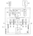
図1は、本発明の実施の一形態として情報機器のセキュリティ確保方法を実現する電子機器の概略的な電気的構成を示す。本実施形態の情報機器は、携帯型電子機器21、電子鍵22およびドッキングステーション23を含む。電子鍵22は、基本的に図6に示す電子鍵2と同等である。ドッキングステーション23については後述する。
【0029】
本実施形態の携帯型電子機器21は、マイクロコンピュータ26、フラッシュROM27、無線通信制御部28および送受信アンテナ29を含むセキュリティ機能関連回路31と、鍵入力スイッチ32、電源33、電子スイッチ34、主回路35およびドッキングステーションI/F部36を含む。これらの携帯型電子機器21としての構成は、図6に示す携帯型電子機器1で、マイクロコンピュータ6、フラッシュROM7、無線通信制御部8および送受信アンテナ9を含むセキュリティ機能関連回路11と、鍵入力スイッチ12、電源13、電子スイッチ14、主回路15およびドッキングステーションI/F部16とそれぞれ対応する。ただしマイクロコンピュータ26およびフラッシュROM27は、無線通信制御部38および送受信アンテナ39とともに、接続時セキュリティ機能関連回路40にも含まれる。
【0030】
電子スイッチ34は、主回路35に対する電源33からの電力供給を制御するために設けられ、主回路35へのメイン電源がOFFの状態で、鍵入力手段としての鍵入力スイッチ32に電子鍵22が挿入されれば、電源33からセキュリティ機能関連回路31に動作用の電力を供給することができる。セキュリティ機能関連回路31に動作用の電力が供給されると、電子鍵22から固有の識別情報であるIDを識別情報入力手段としての無線通信制御部28が送受信アンテナ29を介して受信し、マイクロコンピュータ26に受信IDを入力する。起動制御手段としてのマイクロコンピュータ26は、フラッシュROM27に予め登録されている電子鍵用IDを参照し、参照した結果が一致すれば、電子スイッチ34を制御して主回路35に電源33からのメイン電源を供給する。
【0031】
また、接続検出手段としてのドッキングステーションI/F部36にも、主回路35にメイン電源をOFFとしている状態で電源33から動作用の電力を供給する。ドッキングステーションI/F部36を動作中のドッキングステーション23に接続すると、接続時セキュリティ機能関連回路40に動作用電力が供給され、ドッキングステーション23から伝送されるIDを無線通信制御部38が送受信アンテナ39を介して受信し、マイクロコンピュータ26に入力してフラッシュROM27に予め登録されているIDと照合する。照合結果が一致すれば、マイクロコンピュータ26が電子スイッチ34を導通させ、電源33からのメイン電源を主回路35に供給して携帯型電子機器21としての使用部分を動作させる。なお、電子鍵22が挿入されることを鍵入力スイッチ32によって検出すると、マイクロコンピュータ26がその動作を認識し、電源33からセキュリティ機能関連回路31に電力が供給されるように制御するような構成も可能である。また、ドッキングステーションI/F部36にドッキングステーション23が接続されることを認識して、電源33から接続時セキュリティ機能関連回路40に電力が供給されるように制御することも可能である。
【0032】
接続時セキュリティ機能関連回路40の無線通信制御部38は、電力が供給されると、ドッキングステーション23に対してIDの送信指令を送り、ドッキングステーション23からIDを受信する制御を行う。フラッシュROM27には、携帯型電子機器21に登録されているIDが格納されている。マイクロコンピュータ26は、ドッキングステーション23から受信するIDと、携帯型電子機器21に対して登録されているドッキングステーション用のIDとを比較した結果、一致する場合に電源33から主回路35に電力を供給するように電子スイッチ34を制御する。
【0033】
図2は、図1の電子鍵22の概略的な電気的構成を示す。電子鍵22は、ICチップ41を備える。ICチップ41は、無線通信制御部42、メモリ43、電源用コンデンサ44および送受信アンテナ45を含む。
【0034】
送受信アンテナ45は、無線通信のためのアンテナである。無線通信制御部42は、携帯型電子機器21からのIDの送信指令の受信、メモリ43からのIDの読出し、およびそのIDの送信など、携帯型電子機器21との送受信のための制御を行う。メモリ43には、電子鍵22としての固有のIDを格納している。電源用コンデンサ44は、送受信アンテナ45に受信する電波からの電力で充電され、無線通信制御部42に電力を供給する。
【0035】
図3は、本実施形態のドッキングステーション23の概略的な電気的構成を示す。ドッキングステーション23は、セキュリティ機能関連回路51、鍵入力スイッチ52、電源53、電子スイッチ54、主回路55、マイクロコンピュータ56、フラッシュROM57、無線通信制御部58および送受信アンテナ59を含む。マイクロコンピュータ56、フラッシュROM57、無線通信制御部58および送受信アンテナ59は、セキュリティ機能関連回路51内に含まれる。これらドッキングステーション23で、セキュリティ機能関連回路51、鍵入力スイッチ52、電源53、電子スイッチ54、主回路55、マイクロコンピュータ56、フラッシュROM57、無線通信制御部58および送受しアンテナ59は、図1に示す携帯型電子機器21でのセキュリティ機能関連回路31、鍵入力スイッチ32、電源33、電子スイッチ34、主回路35、マイクロコンピュータ26、フラッシュROM27、無線通信制御部28および送受信アンテナ29にそれぞれ対応する。ドッキングステーション23には、さらに無線通信制御部68および送受信アンテナ69も含まれる。
【0036】
マイクロコンピュータ56は、電子鍵22によって鍵入力スイッチ52が押されたことを認識すると、電源53からセキュリティ機能関連回路51に電力が供給されるように制御する。すなわち鍵入力スイッチ52は、セキュリティ機能関連回路51の電源スイッチとして機能する。鍵入力スイッチ52が機械的なスイッチで、直接電源53からセキュリティ機能関連回路51に電力を供給することもできる。
【0037】
無線通信制御部58は、セキュリティ機能関連回路51に電力が供給されると、電子鍵22に対してIDの送信指令を送り、電子鍵22からIDを受信する制御を行う。マイクロコンピュータ56は、電子鍵22からIDを正常に受信したら電源53から主回路55に電力を供給するように電子スイッチ54を制御する。マイクロコンピュータ56は、さらに受信したIDから特定のIDに変換し、識別情報記憶手段としてのフラッシュROM57に書込みを行う。IDの変換方法の例を、次の表1に示す。
【0038】
【表1】

この例では、同じグループの人のIDを全て或る特定のIDに変換する。たとえばユーザ名が1〜6の6名に対し、グループ名A,B,Cの3組に分ける場合を想定する。各ユーザに対応する電子鍵22のID20005001〜20005006を、20001001〜20001003のドッキングステーションに登録するIDとしてのグループIDに変換する。この結果、ドッキングステーション23に接続する携帯型電子機器21は、パワーオン可能な場合と可能でない場合が生じる。次の表2は、表1に示すようなグループ分けで、パワーオンが可能な場合を○印で示し、可能でない場合を×印で示す。
【0040】
【表2】
表2に示すように、ドッキングステーション23を起動したユーザと同じグループのユーザが携帯型電子機器21のユーザである場合にのみ動作中のドッキングステーション23に携帯型電子機器21を接続するだけで、携帯型電子機器21をパワーオンして起動させることが可能となる。これによって、グループ間でセキュリティ管理を図ることが可能となる。グループ内のメンバがドッキングステーション23を起動していれば、携帯型電子機器21には電子鍵22を挿入しなくても起動が可能となるので、利便性を向上させることができる。
【0042】
ドッキングステーション23から、グループIDあるいはユーザIDを携帯型電子機器21に伝送するために、識別情報伝送手段としての無線通信制御部68および送受信アンテナ69が設けられる。無線通信制御部68は、携帯型電子機器21からの送信指令を受信し、フラッシュROM57からIDを読出し、およびそのIDの送信など、携帯型電子機器21との送受信のための制御を行う。
【0043】
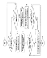
図4は、本実施形態で携帯型電子機器21がセキュリティ確保のための制御を行う手順を示す。ステップa0から手順を開始し、ステップa1では電子鍵22によって鍵入力スイッチ32が押されているか否かを判断する。鍵入力スイッチ32が押されていると判断されるときには、ステップa2で携帯型電子機器のセキュリティ機能関連回路31に電源を供給する。次にステップa3では、携帯型電子機器の無線通信制御部28が電子鍵22からIDを受信する。ステップa4では、受信したIDとフラッシュROM27に登録されているIDとを比較した結果、一致するか否かを判断する。一致していると判断されるときには、ステップa5で携帯型電子機器21の主回路35に電源供給を行う。
【0044】
ステップa1で、電子鍵22によって鍵入力スイッチ22が押されていないと判断されるときには、ステップa6でドッキングステーション23と接続されているか否かを判断する。ドッキングステーション23とも接続されていないと判断されるときには、ステップa1に戻る。ステップa6でドッキングステーション23と接続されたと判断されるときには、ステップa7で携帯型電子機器21の接続時セキュリティ機能関連回路40に電源供給を行う。ステップa8では、携帯型電子機器21の無線通信制御部38がドッキングステーション23からIDを受信する。ステップa9では、受信したIDとフラッシュROM27にドッキングステーション用に登録されているIDとを比較した結果、一致しているか否かを判断する。一致していると判断されるときには、ステップa5で携帯型電子機器21の主回路35に電源供給を行う。ステップa5で主回路35に電源供給を行った後、またはステップa4やステップa9で受信IDと登録IDとが一致しないと判断されるときには、ステップa10で手順を終了する。
【0045】
図5は、図1のドッキングステーション23でのセキュリティ確保のための処理手順を示す。ステップb0から手順を開始し、ステップb1では電子鍵22によって鍵入力スイッチ52が押されるのを待つ。鍵入力スイッチ52が押されると、ステップb2でドッキングステーション23のセキュリティ機能関連回路51に電源供給を行う。ステップb3では、ドッキングステーション23の無線通信制御部58が電子鍵22からIDを受信する。ステップb4では、電子鍵22からIDを正常に受信しているか否かを判断する。IDを正常に受信すると、ステップb5で、ドッキングステーション23の主回路55に電源供給を行う。ステップb6では、受信IDから特定のIDへの変換を行う。ステップb7では、変換後のIDをドッキングステーション27のフラッシュROM57に書込む。
【0046】
ステップb8では、ドッキングステーション23に携帯型電子機器21が接続されて、ID送信要求が受信されるか否かを判断する。ID送信要求が受信されると、ステップb9でフラッシュROMに書込まれたIDを携帯型電子機器21に送信する。ステップb8でID送信要求が受信されないとき、またはステップb9の後、ステップb10に移る。ステップb10では、電源スイッチなどがOFFに操作されて、ドッキングステーション23の使用が終了されているか否かを判断する。使用の終了でないと判断されるときには、ステップb11で電子鍵22が新たに挿入されているか否かを判断する。電子鍵22が挿入されなければ、ステップb8に戻る。ステップb11で新たに電子鍵22が挿入されていると判断されれば、ステップb3に戻る。ステップb10で使用終了と判断されるとき、またはステップb4で電子鍵22からIDを正常に受信していないと判断されるときには、ステップb12で手順を終了する。
【0047】
以上説明した図5に示す処理手順では、ドッキングステーション23を起動した電子鍵22のIDをフラッシュROM57に書込む。ドッキングステーション23は、起動時のみ電子鍵22を必要とし、起動が終了すれば電子鍵22は除去可能である。ただし動作中に他の電子鍵22を挿入すると、最後に挿入した電子鍵22に設定されているIDを正常に受信することができれば、そのIDをフラッシュROM57に書込むようにすることができる。このようにすると、最後に使用した電子鍵22に従って、ドッキングステーション23と接続するだけで起動することができる携帯型電子機器21を変えることができる。
【0048】
また、本実施形態で用いるIDは、固定した一定のデータを用いることができるばかりではなく、日時などの変化する情報に基づいて一定の関数で変化するデータを用いるようにすることもできる。
【0049】
【発明の効果】
以上のように本発明によれば、ドッキングステーションを起動するためにも電子鍵が必要となるため、ドッキングステーションはセキュリティが確保された状態で動作中となり、携帯型電子機器は単体で動作するときに電子鍵でセキュリティの確保を図り、ドッキングステーションと接続するときには動作中のドッキングステーションに接続するだけでセキュリティを確保しながら携帯型電子機器を起動することができる。電子鍵を持たない利用者は、動作中のドッキングステーションと接続するときのみ携帯型電子機器を起動させることができ、ドッキングステーション側でセキュリティを確保した状態で携帯型電子機器の利用を図ることができる。電子鍵を有する利用者は、携帯型電子機器を単体で起動して利用することができる。
【0050】
また本発明によれば、携帯型電子機器に電子鍵が挿入されたときには、挿入された電子鍵の識別情報の照合によって起動制御し、携帯型電子機器に電子鍵が挿入されていないときには、ドッキングステーションに挿入された電子鍵の携帯型電子機器の単体だけではなく、ドッキングステーションも含めた全体的なセキュリティを確保することができる。
【図面の簡単な説明】
【図1】本発明の実施の一形態としての情報機器のセキュリティ確保方法を実行するために必要な概略的な電気的構成を示すブロック図である。
【図2】図1の電子鍵22の概略的な電気的構成を示すブロック図である。
【図3】図1のドッキングステーション23の概略的な電気的構成を示すブロック図である。
【図4】図1の携帯型電子機器21でのセキュリティ確保のための処理手順を示すフローチャートである。
【図5】図1のドッキングステーション23でのセキュリティ確保のための処理手順を示すフローチャートである。
【図6】従来技術でセキュリティ確保を図っている携帯型電子機器をドッキングステーションに接続している時の概略的な電気的構成を示すブロック図である。
【図7】図6の携帯型電子機器でのセキュリティ確保のための処理手順を示すフローチャートである。
【符号の説明】
21 携帯型電子機器
22 電子鍵
23 ドッキングステーション
26,56 マイクロコンピュータ
27,57 フラッシュROM
28,38,58,68 無線通信制御部
29,39,45,59,69 送受信アンテナ
31,51 セキュリティ機能関連回路
32,52 鍵入力スイッチ
33,53 電源
34,54 電子スイッチ
35,55 主回路
36 ドッキングステーションI/F部
40 接続時セキュリティ機能関連回路
41 ICチップ
43 メモリ
44 電源用コンデンサ[0001]
BACKGROUND OF THE INVENTION
In the present invention, a portable electronic device that can be used alone is connected to a docking station.Start-up control method for portable electronic deviceandPortable electronic devicesAbout.
[0002]
[Prior art]
Conventionally, portable electronic devices for information processing called notebook computers and PDAs (Personal Digital Assistants) can be used alone or at the same time in combination with expansion units called docking stations. May have been. For example, Japanese Patent Laid-Open No. 2000-112580 discloses a computer in which a personal computer can be automatically powered on when a notebook personal computer, that is, a notebook personal computer, is attached to an expansion unit that is a docking station for function expansion. Prior art on the system is disclosed. This prior art docking station is provided to allow connection to a LAN (Local Area Network). In general, the docking station is used to compensate for the fact that portable electronic devices place importance on portability and thus cannot mount sufficient hardware. Therefore, in many cases, the docking station is directly connected to a large-capacity storage device or connected to a large-capacity storage device via a LAN. Such storage devices store important information and must prevent unauthorized persons from reading the information or modifying the information.
[0003]
Generally, in a computer device used for important business or the like, security is ensured in order to limit access to information to those who have a legitimate authority. For example, in a logon procedure performed when starting to use a computer device, the operator's qualification is confirmed by inputting an ID, which is identification information, or by confirming a password. In order to ensure even more secure security, electronic keys are also used. A security system using an electronic key for a portable electronic device has been filed by the present applicant as Japanese Patent Application No. 10-185141 and published as Japanese Patent Application Laid-Open No. 2000-17918. In this patent application, a technology for a security system comprising an electronic key having a built-in key data transmitting unit for transmitting unique key data, and a portable electronic device having a keyhole for inserting the electronic key and a key data receiving unit Is disclosed. However, nothing is shown about security management of the entire system including the docking station by combining the portable electronic device with the docking station.
[0004]
FIG. 6 shows an electrical configuration when the portable electronic device using the electronic key shown in the above-mentioned patent application enables connection to the docking station. The portable
[0005]
The
[0006]
FIG. 7 shows a security management processing procedure in the system shown in FIG. The procedure is started from step s0. In step s1, it is determined whether or not the
[0007]
In step s 3, the wireless communication control unit 8 provided in the security function
[0008]
When it is determined in step s1 that the
[0009]
As shown in FIG. 7, when the
[0010]
[Problems to be solved by the invention]
In the security system disclosed in the above-mentioned patent application, although security management can be performed as a single electronic device system, security management as a whole system including the
[0011]
If the
[0012]
Further, a configuration in which a plurality of users own portable electronic devices and use a
[0013]
An object of the present invention is to ensure overall security including not only a single portable electronic device but also a docking station.Start-up control method for portable electronic deviceandPortable electronic devicesIs to provide.
[0014]
[Means for Solving the Problems]
The present inventionAn activation control method for a portable electronic device capable of connecting a docking station for outputting a predetermined electronic key in which identification information is set and outputting identification information set in the inserted electronic key,
A key detection step of detecting whether or not a predetermined electronic key in which the identification information is set is inserted;
A connection detection step of detecting a connection with the docking station;
In the key detection step, when it is detected that a predetermined electronic key in which the identification information is set is inserted, the identification information set in the inserted electronic key is registered in advance. The identification information is collated to determine whether or not to supply power to the main circuit, and in the key detection step, it is detected that the predetermined electronic key set with the identification information is not inserted. When the connection detection step detects a connection with the docking station, the identification information output from the connected docking station is compared with the identification information registered in advance to supply power to the main circuit. An activation control step for determining whether or not to performIt is characterized byStart-up control of portable electronic devicesIs the method.
[0015]
According to the present invention, a portable electronic device that operates alone or connected to a docking stationofFor security,Use an electronic key. Portable electronic devicesIs, Identification informationSet upCan be insertedThere, Insert electronic keyIs set to the inserted electronic keyIdentification informationThePre-registered identification information andTheMatchIt is determined whether to supply power to the main circuit. Further, when it is detected that the predetermined electronic key in which the identification information is set is not inserted into the portable electronic device, it is detected whether the docking station is connected to the portable electronic device, and the docking station The output identification information and the identification information registered in advance in the portable electronic device are collated, and based on the collation result, it is determined whether to supply power to the portable electronic device. Thus, in portable electronic devicesDocking stationButConnectionEven if notStart up your portable electronic device,Security can be ensured.
[0016]
The present invention also providesA portable electronic device that can be connected to a docking station that outputs a predetermined electronic key in which identification information is set and an identification information set in the inserted electronic key,
A detecting unit that can insert a predetermined electronic key in which identification information is set and detects whether the electronic key is inserted;
Connection detecting means for detecting connection with the docking station,
When the detection unit detects that the predetermined electronic key with the identification information set is inserted, the identification information set for the inserted electronic key and the identification information registered in advance To determine whether or not to supply power to the main circuit, detect that the predetermined electronic key is not inserted, and connect to the docking station by the connection detecting means. An activation control means for determining whether or not to supply power to the main circuit by comparing the identification information output from the connected docking station with the identification information registered in advance when detected; includingIt is characterized by that.
[0017]
According to the present invention,The portable electronic device is activated by the identification information of the electronic key when the electronic key is inserted, or by the identification information of the electronic key inserted in the docking station when the electronic key is not inserted.can do.Therefore,A portable electronic device does not start by simply being connected to an operating docking station.Therefore, the portable electronic device detects whether or not an electronic key is inserted, connection detection means that detects whether or not a docking station is connected, and whether or not to supply power to the main circuit. Activation control means for making the above determination.
When it is detected by the detection means that the electronic key is inserted, the identification information set in the inserted electronic key and the activation control means collate the identification information registered in advance, It is determined whether or not to supply power to the main circuit. In addition, when the activation control unit detects that the docking station is connected by the connection detection unit while detecting that the electronic key is not inserted, the activation control unit detects the identification information output from the connected docking station, It is determined whether or not power is supplied to the main circuit by comparing with identification information registered in advance in the type electronic device.
[0028]
DETAILED DESCRIPTION OF THE INVENTION
FIG. 1 shows a schematic electrical configuration of an electronic device that realizes a security ensuring method for an information device as an embodiment of the present invention. The information device according to the present embodiment includes a portable
[0029]
The portable
[0030]
The
[0031]
In addition, power for operation is supplied from the
[0032]
When the power is supplied, the wireless
[0033]
FIG. 2 shows a schematic electrical configuration of the
[0034]
The transmission /
[0035]
FIG. 3 shows a schematic electrical configuration of the
[0036]
When the
[0037]
When power is supplied to the security function related
[0038]
[Table 1]
In this example, all the IDs of people in the same group are converted into a specific ID. For example, it is assumed that six
[0040]
[Table 2]
As shown in Table 2, only when the user of the same group as the user who started the
[0042]
In order to transmit a group ID or a user ID from the
[0043]
FIG. 4 shows a procedure in which the portable
[0044]
If it is determined in step a1 that the
[0045]
FIG. 5 shows a processing procedure for ensuring security in the
[0046]
In step b8, it is determined whether the portable
[0047]
In the processing procedure shown in FIG. 5 described above, the ID of the electronic key 22 that activated the
[0048]
The ID used in the present embodiment can use not only fixed fixed data but also data that changes with a fixed function based on changing information such as date and time.
[0049]
【The invention's effect】
As described above, according to the present invention, since an electronic key is required to activate the docking station, the docking station is operating in a state where security is ensured, and the portable electronic device is operated alone. In order to ensure security with an electronic key and connect to a docking station, the portable electronic device can be activated while ensuring security simply by connecting to the operating docking station. A user who does not have an electronic key can activate a portable electronic device only when connected to an operating docking station, and can use the portable electronic device while ensuring security on the docking station side. it can. A user having an electronic key can activate and use a portable electronic device alone.
[0050]
Also according to the invention,When the electronic key is inserted into the portable electronic device, activation control is performed by collating the identification information of the inserted electronic key. When the electronic key is not inserted into the portable electronic device, the electronic key inserted into the docking station is controlled. As well as a single portable electronic device, overall security including docking station can be ensured.
[Brief description of the drawings]
FIG. 1 is a block diagram showing a schematic electrical configuration necessary for executing a security ensuring method for an information device as an embodiment of the present invention.
2 is a block diagram showing a schematic electrical configuration of the
FIG. 3 is a block diagram showing a schematic electrical configuration of the
4 is a flowchart showing a processing procedure for ensuring security in the portable
FIG. 5 is a flowchart showing a processing procedure for ensuring security in the
FIG. 6 is a block diagram showing a schematic electrical configuration when a portable electronic device for which security is ensured in the prior art is connected to a docking station.
7 is a flowchart showing a processing procedure for ensuring security in the portable electronic device of FIG. 6;
[Explanation of symbols]
21 Portable electronic devices
22 Electronic key
23 Docking station
26,56 microcomputer
27,57 Flash ROM
28, 38, 58, 68 Wireless communication control unit
29, 39, 45, 59, 69 Transmitting and receiving antennas
31, 51 Security function related circuit
32, 52 Key input switch
33,53 Power supply
34, 54 Electronic switch
35,55 Main circuit
36 Docking station I / F part
40 Security function related circuit when connected
41 IC chip
43 memory
44 Power supply capacitor
Claims (2)
前記識別情報が設定されている所定の電子鍵が挿入されているか否かを検知する鍵検知ステップと、
前記ドッキングステーションとの接続を検出する接続検出ステップと、
前記鍵検知ステップにおいて、前記識別情報が設定されている所定の電子鍵が挿入されていることを検知したとき、当該挿入されている電子鍵に設定されている識別情報と、予め登録されている識別情報とを照合して、主回路への電力供給を行なうか否かの判断を行なうとともに、前記鍵検知ステップにおいて前記識別情報が設定されている所定の電子鍵が挿入されていないことを検知し、かつ前記接続検出ステップにおいてドッキングステーションとの接続を検出したとき、接続されているドッキングステーションから出力される識別情報と、予め登録されている識別情報と照合して、主回路への電力供給を行なうか否かの判断を行なう起動制御ステップとを、含むことを特徴とする携帯型電子機器の起動制御方法。 An activation control method for a portable electronic device capable of connecting a docking station for outputting a predetermined electronic key in which identification information is set and outputting identification information set in the inserted electronic key,
A key detection step of detecting whether or not a predetermined electronic key in which the identification information is set is inserted;
A connection detection step of detecting a connection with the docking station;
In the key detection step, when it is detected that a predetermined electronic key in which the identification information is set is inserted, the identification information set in the inserted electronic key is registered in advance. The identification information is collated to determine whether or not to supply power to the main circuit, and in the key detection step, it is detected that the predetermined electronic key set with the identification information is not inserted. When the connection detection step detects a connection with the docking station, the identification information output from the connected docking station is compared with the identification information registered in advance to supply power to the main circuit. start control method for a portable electronic device, characterized in that the activation control step of performing performing determination of whether the include.
識別情報が設定されている所定の電子鍵が挿入可能で、当該電子鍵が挿入されているか否かを検知する検知手段と、
前記ドッキングステーションとの接続を検出する接続検出手段とを備え、
前記検知手段によって前記所定の電子鍵が挿入されていることを検知したとき、当該挿入されている電子鍵に設定されている識別情報と、予め登録されている識別情報とを照合して、主回路への電力供給を行なうか否かの判断を行なうとともに、前記所定の電子鍵が挿入されていないことを検知し、かつ前記接続検出手段によってドッキングステーションとの接続を検出したとき、接続されているドッキングステーションから出力される識別情報と、予め登録されている識別情報とを照合して、主回路への電力供給を行なうか否かの判断を行なう起動制御手段とを、含むことを特徴とする携帯型電子機器。 A portable electronic device that can be connected to a docking station that inserts a predetermined electronic key in which identification information is set and outputs identification information set in the inserted electronic key,
A detecting unit that can insert a predetermined electronic key in which identification information is set and detects whether the electronic key is inserted;
Connection detecting means for detecting connection with the docking station,
When the detection means detects that the predetermined electronic key is inserted, the identification information set in the inserted electronic key is compared with the identification information registered in advance, When it is determined whether or not to supply power to the circuit, the predetermined electronic key is not inserted, and the connection detecting unit detects a connection with the docking station, the connection is established And an activation control means for determining whether or not to supply power to the main circuit by comparing the identification information output from the docking station with the identification information registered in advance. Portable electronic devices .
Priority Applications (1)
| Application Number | Priority Date | Filing Date | Title |
|---|---|---|---|
| JP2000265549A JP4438199B2 (en) | 2000-09-01 | 2000-09-01 | Start-up control method for portable electronic device and portable electronic device |
Applications Claiming Priority (1)
| Application Number | Priority Date | Filing Date | Title |
|---|---|---|---|
| JP2000265549A JP4438199B2 (en) | 2000-09-01 | 2000-09-01 | Start-up control method for portable electronic device and portable electronic device |
Publications (3)
| Publication Number | Publication Date |
|---|---|
| JP2002073197A JP2002073197A (en) | 2002-03-12 |
| JP2002073197A5 JP2002073197A5 (en) | 2008-05-22 |
| JP4438199B2 true JP4438199B2 (en) | 2010-03-24 |
Family
ID=18752797
Family Applications (1)
| Application Number | Title | Priority Date | Filing Date |
|---|---|---|---|
| JP2000265549A Expired - Fee Related JP4438199B2 (en) | 2000-09-01 | 2000-09-01 | Start-up control method for portable electronic device and portable electronic device |
Country Status (1)
| Country | Link |
|---|---|
| JP (1) | JP4438199B2 (en) |
Cited By (1)
| Publication number | Priority date | Publication date | Assignee | Title |
|---|---|---|---|---|
| US11599321B2 (en) | 2018-02-23 | 2023-03-07 | Samsung Electronics Co., Ltd | Electronic device and operating method therefor |
Families Citing this family (2)
| Publication number | Priority date | Publication date | Assignee | Title |
|---|---|---|---|---|
| US7975089B2 (en) * | 2009-05-07 | 2011-07-05 | Hewlett-Packard Development Company, L.P. | Computer dock providing for disconnecting media from docking port when lock is inserted |
| JP5782963B2 (en) * | 2011-09-28 | 2015-09-24 | 富士通株式会社 | Expansion device, information processing device, information processing system, and information processing system security processing method |
-
2000
- 2000-09-01 JP JP2000265549A patent/JP4438199B2/en not_active Expired - Fee Related
Cited By (1)
| Publication number | Priority date | Publication date | Assignee | Title |
|---|---|---|---|---|
| US11599321B2 (en) | 2018-02-23 | 2023-03-07 | Samsung Electronics Co., Ltd | Electronic device and operating method therefor |
Also Published As
| Publication number | Publication date |
|---|---|
| JP2002073197A (en) | 2002-03-12 |
Similar Documents
| Publication | Publication Date | Title |
|---|---|---|
| JP4194172B2 (en) | Image display device and inter-device communication method | |
| KR101176692B1 (en) | Mass storage device with near field communications | |
| US8000755B2 (en) | Information-communication terminal device and automatic backup system including the same | |
| US20060176146A1 (en) | Wireless universal serial bus memory key with fingerprint authentication | |
| CN104537291A (en) | Screen interface unlocking method and screen interface unlocking device | |
| JP2001312326A (en) | Portable electronic device and battery pack for portable electronic device | |
| CN100465890C (en) | System and method for downloading ROM image to wireless terminal | |
| JP2973723B2 (en) | Subscriber information setting method for mobile phones | |
| JP2001175602A (en) | Method for establishing communication terminal connection and communication system | |
| CN111383397A (en) | Mobile power supply charging terminal and mobile power supply leasing method | |
| JP4438199B2 (en) | Start-up control method for portable electronic device and portable electronic device | |
| JP4910313B2 (en) | Authentication server and authentication program | |
| JP6249350B2 (en) | Security printing system, security printing method, and image forming apparatus | |
| JP2003188954A (en) | Charger | |
| JP2006060392A (en) | Unauthorized-use preventive system and identification method for information terminal device | |
| JPH08314805A (en) | System for preventing portable radio terminal from being illegally used and method for executing the same | |
| JP2005117430A (en) | Unauthorized use preventing method and portable terminal when lost | |
| JP2002236572A (en) | Print system | |
| JP2002366938A (en) | System for authenticating fingerprint | |
| JP3733167B2 (en) | Information processing apparatus, image information transfer method, and mail reception method | |
| JP4030936B2 (en) | External storage device | |
| JP3883629B2 (en) | Image input system | |
| CN212569938U (en) | Mobile power supply charging terminal with identity information identification module | |
| KR20050096577A (en) | Security system using mobile phone and method therefor | |
| JP2003188791A (en) | Mobile communication terminal and control method for mobile communication terminal |
Legal Events
| Date | Code | Title | Description |
|---|---|---|---|
| A621 | Written request for application examination |
Free format text: JAPANESE INTERMEDIATE CODE: A621 Effective date: 20070830 |
|
| A521 | Written amendment |
Free format text: JAPANESE INTERMEDIATE CODE: A523 Effective date: 20080404 |
|
| TRDD | Decision of grant or rejection written | ||
| A01 | Written decision to grant a patent or to grant a registration (utility model) |
Free format text: JAPANESE INTERMEDIATE CODE: A01 Effective date: 20091222 |
|
| A01 | Written decision to grant a patent or to grant a registration (utility model) |
Free format text: JAPANESE INTERMEDIATE CODE: A01 |
|
| A61 | First payment of annual fees (during grant procedure) |
Free format text: JAPANESE INTERMEDIATE CODE: A61 Effective date: 20091228 |
|
| FPAY | Renewal fee payment (event date is renewal date of database) |
Free format text: PAYMENT UNTIL: 20130115 Year of fee payment: 3 |
|
| R150 | Certificate of patent or registration of utility model |
Free format text: JAPANESE INTERMEDIATE CODE: R150 |
|
| FPAY | Renewal fee payment (event date is renewal date of database) |
Free format text: PAYMENT UNTIL: 20130115 Year of fee payment: 3 |
|
| LAPS | Cancellation because of no payment of annual fees |