JP4426662B2 - Stereo microscope - Google Patents
Stereo microscope Download PDFInfo
- Publication number
- JP4426662B2 JP4426662B2 JP01465999A JP1465999A JP4426662B2 JP 4426662 B2 JP4426662 B2 JP 4426662B2 JP 01465999 A JP01465999 A JP 01465999A JP 1465999 A JP1465999 A JP 1465999A JP 4426662 B2 JP4426662 B2 JP 4426662B2
- Authority
- JP
- Japan
- Prior art keywords
- image
- optical system
- microscope
- light beam
- surgical microscope
- Prior art date
- Legal status (The legal status is an assumption and is not a legal conclusion. Google has not performed a legal analysis and makes no representation as to the accuracy of the status listed.)
- Expired - Fee Related
Links
Images


Landscapes
- Microscoopes, Condenser (AREA)
Description
【0001】
【発明の属する技術分野】
本発明は、観察視野内に顕微鏡画像やモニター画像のように、互いに異なる様々な画像情報を表示できる実体顕微鏡であって、特に、ナビゲーションシステムをはじめとした外科手術支援装置を併用する場合に好適な手術用顕微鏡に関する。
【0002】
【従来の技術】
従来より手術用顕微鏡をはじめとする実体顕微鏡は、脳神経外科,耳鼻咽喉科,眼科等の外科手術に用いられ、術部を拡大観察することによって、手術の能率を向上させる等の重要な役割を果たしている。
さらに、近年、手術用顕微鏡は、手術をより低侵襲に行うために、術前に術部周辺のCTやMRI等の医用画像を撮影し、それらの画像をコンピューターで統合処理して腫瘍部位の位置や範囲の確認等を行う外科手術支援装置、いわゆるナビゲーションシステムと併用されている。
このナビゲーションシステムと手術用顕微鏡との連携によって、術者が観察している位置から何ミリ先のどの位置にどれくらいの大きさの腫瘍があるといった情報をコンピューター画像として提供することができる。
さらに、現在では、手術用顕微鏡の光学観察像上に直接腫瘍の範囲等を重ねて表示できる技術が開発されている。
【0003】
このような手術用顕微鏡画像と手術用顕微鏡以外の画像情報とを重ね合わせて表示する技術に関しては、特開平5−215971号公報に開示されているもの等が知られている。
図17はこの公報に開示されている手術用顕微鏡の構成を示す図である。ここに示さた手術用顕微鏡1は光路分割手段2を備えており、この光路分割手段2によって、観察光路3と撮影光学系4への光路とに分割している。さらに、この手術用顕微鏡1は、光路合成手段5を備え、画像表示手段6からの光路7と観察光路3とを重ね合わせて、これを双眼光学系8へ導くことを可能にしている。
したがって、この手術用顕微鏡1を用いることにより、術者は顕微鏡画像と画像表示手段6に表示された画像とを重ねて観察することができるため、顕微鏡画像を観察しながら、例えば腫瘍の範囲,腫瘍までの到達距離等手術に有用な情報を顕微鏡画像上から直接得ることができる。
【0004】
しかしながら、この手術用顕微鏡1では、顕微鏡画像の観察光路3内に新たに顕微鏡画像の観察光路3と画像表示手段6からの光路7とを重ね合わせるための光路合成手段5を設けているため、顕微鏡画像の明るさが低下してしまうという欠点がある。
また、手術用顕微鏡1において、観察者の両眼で画像を重ねて観察することを可能にした場合、光路合成手段5や画像表示手段6、画像表示手段6から射出される光束を光路合成手段5に入射させる光学系をそれぞれ1対配置しなければならず、手術用顕微鏡鏡体部の大型化や重量化を招くことになる。さらに、この場合、光路合成手段5が顕微鏡観察光路上に積み重なるような配置となるため、被観察物体から観察者のアイポイントまでの距離が長くなってしまう。
【0005】
【発明が解決しようとする課題】
手術用顕微鏡においては、作業性を向上させるために、十分な明るさの顕微鏡画像を確保することはもとより、手術用顕微鏡鏡体部の小型軽量化、被観察物体から観察者のアイポイントまでの距離を手術用顕微鏡を使わない状態とできるだけ同等に近づけることは必須の条件である。
しかしながら、これらの必須の条件は、前記特開平5−215971号公報に開示された技術からでは得られない。
【0006】
本発明は、上記のような従来技術の有する問題点に鑑みなされたものであり、その目的は、観察者が両眼で、またはTV撮影装置,写真撮影装置で、顕微鏡画像とモニターに表示される画像情報とを重ね合わせた像を観察および撮像することができ、且つ、顕微鏡画像の明るさの低下や、顕微鏡鏡体部の大型重量化,被観察物体から観察者のアイポイントまでの距離の増加等のない、作業性の優れた実体顕微鏡を提供することにある。
【0007】
【課題を解決するための手段】
上記目的を達成するため、本発明は次のような特徴を備えている。
【0009】
本発明の実体顕微鏡は、立体観察光学系を有する実体顕微鏡において、物体からの光束を受け該光束をアフォーカル光束にする1つの対物光学系と該対物光学系からの光束を受け変倍を行う1つの変倍光学系とからなる単眼光学系と、該単眼光学系からの光束を受け観察者の左右の眼に導いて1対の観察像を結像する少なくとも1つの双眼鏡筒光学系とを備え、前記単眼光学系中に1つの光路合成手段を配置し、該1つの光路合成手段に対し、前記立体観察光学系の近傍に配置した1つの画像表示手段上に表示される画像から射出する光束を画像投影光学系を介して入射させ、観察光路に前記画像表示手段からの光束を分け入れるようにすると共に、前記双眼鏡筒光学系のハウジング内に、前記双眼鏡筒光学系,前記画像表示手段及び画像投影光学系とは別体の、少なくとも1対の画像表示手段と画像投影光学系を配置したことを特徴とする。
【0011】
【発明の実施の形態】
図1は、本発明の参考例にかかる実体顕微鏡の概略構成を示す光軸に沿う断面図である。
この実体顕微鏡は、被観察物体10からの光束を受けこれをアフォーカル光束にする対物レンズ11と、対物レンズ11からの光束を受けこれを変倍する変倍レンズ12を備え、単眼光学系を構成している。さらに、画像表示手段13と、画像表示手段13からの光束を受けこれをアフォーカル光束にする画像投影光学系14と、この画像投影光学系14を経た光路を変倍レンズ12を経た観察光路15に重ね合わせるための光路合成手段16と、観察光路15に導かれた光束を観察者17の両眼へ導くための双眼鏡筒光学系18を備えている。このように構成された実体顕微鏡では、画像表示手段13上に手術に有用な画像を表示させると、この画像情報は画像投影光学系14および光路合成手段16を介して観察光路15へ導かれることによって、観察者17は被観察物体10の顕微鏡画像と画像表示手段13上に表示された手術に有用な情報を含む画像とを重ね合わせた状態で観察することができる。
【0012】
図1に示した実体顕微鏡は、従来のように左右の観察光路中にそれぞれ一対の光路分割手段,画像投影光学系および画像表示手段を配置する必要がなく、1つの画像表示手段13,1つの画像投影光学系14,1つの光路合成手段16により、画像投影光学系14からの光束を双眼鏡筒光学系18の左右の観察光路15へ分け入れることができる。したがって、顕微鏡鏡体部の小型軽量化を実現でき、また被観察物体10から観察者17のアイポイントまでの距離の増加を回避できるため、優れた作業性をもたらす実体顕微鏡となる。
なお、画像表示手段13には、特にナビゲーションシステムによる画像情報や、その他手術に有用な画像を表示するとよい。
【0013】
また、図1に示した実体顕微鏡は、図2に示すように、光路合成手段16を経た観察光路15中に、さらに光路分割手段19を配置し、この光路分割手段19により分割される観察光路15とは別の光路中にさらにもう1つの双眼鏡筒光学系20を配置すれば、2人で同時に観察することができる。
さらに、同様な方法で双眼鏡筒光学系を増やすことによって、複数の観察者の両眼に、顕微鏡画像に顕微鏡画像以外の画像情報を重ね合わせた像を同時に導くことが可能になる。
【0014】
図3は、本発明にかかる実体顕微鏡の概略構成を示す光軸に沿う断面図である。
この実体顕微鏡は、図1に示した実体顕微鏡の双眼鏡筒光学系18に代えて、双眼鏡筒ハウジング21を光路合成手段16を経た観察光路15中に配置したものである。
双眼鏡筒ハウジング21は、内部に、1対の画像表示手段22と、1対の画像投影光学系23と、プリズム24と、結像レンズ25aと接眼レンズ25bとからなる1対の双眼鏡筒光学系25を備えている。画像表示手段22および画像投影光学系23は、画像表示手段13,画像投影光学系14とは役割が異なる。すなわち、図4に示すように、画像表示手段22上に表示した画像は、画像投影光学系23により投影されプリズム24を介して顕微鏡画像26の近傍27に形成される。このときプリズム24は、双眼鏡筒光学系25の結像レンズ25aが形成する顕微鏡画像26の光束の一部を遮るように配置されている。そのため、観察視野内における近傍27の画像は画像表示手段22の画像のみであって、画像表示手段22の画像を通して顕微鏡画像26が見えることはない。この結果、観察者は双眼鏡筒光学系25の接眼レンズ25bを介して、双方の像を鮮明に観察することができる。
なお、顕微鏡画像26には、双眼鏡筒ハウジング21外に配置した画像投影光学系14および光路合成手段16によって画像表示手段13上に表示した画像を入れ込むことができ、この場合、画像表示手段13上に表示された像が顕微鏡画像26と重なって見えるようになる。
【0015】
このような構成であると、例えば図5に示すように、顕微鏡画像と重ねて観察すると互いにスポイルしてしまうような精密で情報量の多い画像28は画像表示手段13ではなく、画像表示手段22上に表示することで、顕微鏡画像26とは別に顕微鏡画像26の近傍27の位置に表示させることができる。一方、図5に示した、マーキングや記号のように情報量が少なく、重ねて表示しても互いにスポイルしないような画像29は、画像表示手段13上に表示することによって、顕微鏡画像26中に取り込まれ、被観察物体10の像と重なり合った状態で観察できるようにすることができる。このように、本発明にかかる実体顕微鏡では、観察者に有用な多くの画像を、その画像の性質に合わせて画質を劣化させることなく、顕微鏡画像と共に観察者に提供することができる。
【0016】
図6は、本発明の他の参考例にかかる実体顕微鏡の概略構成を示す光軸に沿う断面図である。この実体顕微鏡は、被観察物体10からの光束を受けこれをアフォーカル光束にする対物レンズ11と、対物レンズ11からの光束を受けこれを変倍する変倍レンズ12を備えている。さらに、画像表示手段13と、画像表示手段13からの光束を受けこれをアフォーカル光束にする画像投影光学系14と、この画像投影光学系14を経た光路を変倍レンズ12を経た観察光路15に重ね合わせ、且つ撮影光路30へ導くための光路合成手段31と、観察光路15に導かれた光束を観察者17の両眼へ導くための双眼鏡筒光学系18を備えている。また、撮影光路30には、撮影光学系32および撮影素子33を配置している。なお、光路合成手段31は、変倍レンズ12を経て観察光路15へ導かれた光束を撮影光路30へ導く作用も有している。
【0017】
ここに示した実体顕微鏡では、画像表示手段13上に腫瘍範囲マーキング等の画像を表示させると、画像投影光学系14および光路合成手段31により、観察光路15に画像表示手段13からの光束が分け入れられるため、観察者17は被観察物体10の顕微鏡画像と画像表示手段13上に表示した画像とを重ね合わせた状態で観察することができる。
さらに、撮影光路30にも同様に画像表示手段13からの光束が分け入れられるため、被観察物体10の顕微鏡画像と画像表示手段13上に表示した画像とを重ね合わせた画像を撮影できる。
【0018】
図6に示した実体顕微鏡は、従来のように左右の観察光路中にそれぞれ一対の光路分割手段,画像投影光学系,画像表示手段を配置する必要がなく、また、観察光路から撮影光路へ導くための光束を分割する光路分割手段と、画像投影光学系からの光束を観察光路へ分け入れるための光路合成手段を2つ配置する必要もない。すなわち、図6に示した実体顕微鏡は、画像投影光学系14からの光束を双眼鏡筒光学系18の左右観察光路へ分け入れることと、観察光路15からの光束を撮影光路30へ導入することを、1つの画像表示手段13と、1つの画像投影光学系14と、1つの光路合成手段31により実現している。
したがって、顕微鏡鏡体部の小型軽量化を実現し、被観察物体10から観察者17のアイポイントまでの距離の増加を回避でき、優れた作業性を備えた実体顕微鏡となる。また、顕微鏡画像の明るさの低下も防ぐことができる。
【0019】
さらに、この実体顕微鏡では、特にナビゲーションシステムによる画像情報や、その他手術に有用な画像を画像表示手段13に表示するとよい。また、図2に示したものと同様に、光路合成手段31を経た観察光路15中に、さらに光路分割手段を配置し、この光路分割手段により観察光路15から分割される光路中にさらにもう1つの双眼鏡筒光学系を配置すれば、2人で同時に観察することができる。
【0020】
また、この実体顕微鏡では、前記光路合成手段16,31を単眼光学系として構成されている対物レンズ11と変倍レンズ12との間に配置してもよい。この構成であれば、変倍レンズ12による観察像の拡大縮小が顕微鏡画像のみならず、画像表示手段13に表示した画像情報に対しても同様に行われるため、画像表示手段13に表示するマーキング等を、変倍レンズ12の倍率を確認した後に、この倍率に応じて計算し表示し直す必要がなくなり、より単純な構成の実体顕微鏡を提供することができる。
【0021】
また、この実体顕微鏡は、前記画像表示手段13,画像投影光学系14とは別に、立体観察光学系(双眼鏡筒光学系18)の近傍に、1対の画像表示手段と、この画像表示手段からの光束を受けこれをアフォーカル光束にする1対の画像投影光学系と、1対の像反射部材を配置し、これらの画像表示手段,前記画像投影光学系および像反射部材をハウジングに内蔵してユニットを形成し、このユニットを実体顕微鏡鏡体部に対し着脱可能に構成してもよい。
この構成であれば、被観察物体10の顕微鏡画像と画像表示手段13に表示される像を重ね合わせて観察するのが不適である場合、画像表示手段13ではなく、前記ユニット内の画像表示手段に画像を表示することにより、被観察物体10の顕微鏡画像と、前記ユニット内の画像表示手段に表示された像を独立した状態で観察することができる。
【0022】
以下、図示した実施例に基づき本発明をさらに詳細に説明する。なお、以下に示す実施例は全て手術用顕微鏡の例を示すものである。
【0023】
第1参考例
図7は、本参考例にかかる手術用顕微鏡の光学系の構成を示す概略図である。
本参考例の手術用顕微鏡は、対物レンズ34,変倍レンズ35,ビームスプリッター36,前群37aと後群37bからなるリレーレンズ37,およびこれらの間に介在されたミラー,プリズム等の複数の反射部材からなる単眼光学系と、左右光路入替え光学系としての偏角ダハプリズム38と、右眼用,左眼用の双眼光学系を有する双眼鏡筒光学系39を備えている。さらに、本参考例の手術用顕微鏡は、小型のLCD40を備え、画像投影光学系41により、LCD40からの光束をアフォーカル光束とし、これをビームスブリッター36へ導くようになっている。
【0024】
以上のように構成された本参考例の手術用顕微鏡では、被観察物体10から射出される光束を、対物レンズ34,変倍レンズ35,ビームスプリッター36,リレーレンズ37を備えた単眼光学系を通過させ、偏角ダハプリズム38へ導く。この偏角ダハプリズム38は自身を通過する光束を偏角させ、倒立像を形成する作用を有している。したがって、被観察物体10からの光束をこの偏角ダハプリズム38を介在させて双眼鏡筒光学系39へ導くことにより、観察者の右眼に入射すべき光束は右眼に、左眼に入射すべき光束は左眼に入射させることができ、観察者に被観察物体10の正立した立体像を供給することができる。
同時に、LCD40から射出する光束も、画像投影光学系41によリビームスプリッター36へ導かれ、被観察物体10からの光束が導かれる光路中へ導入される。よって、観察者は、LCD40上に表示された画像情報と被観察物体10の顕微鏡画像とを重ね合わせた状態で観察できるようになる。
【0025】
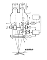
次に、本参考例の手術用顕微鏡をナビゲーションシステムと併用する場合の例を図8に示す。
【0026】
まず、本参考例の手術用顕微鏡42には、ライトガイド43を介して光源44が接続されている。また、手術用顕微鏡42は、ケーブル45を介してカメラコントロールユニット46と接続されている。さらに、このカメラコントロールユニット46はケーブル47を介してカメラユニット48と接続されており、カメラユニット48の先には内視鏡本体49が接続されている。また、内視鏡本体49には、ライトガイド50を介して光源51が接続されている。
【0027】
さらに、手術用顕微鏡42と共に用いるナビゲーションシステム52は、カメラアレイ53とこれに接続されたコンピューター54で構成されている。カメラアレイ53は、2台のカメラを異なる角度でその撮影方向が交差するように同一平面内に配置している。また、手術用顕微鏡42や内視鏡本体49には、カメラアレイ53を通した位置検出のための目印が設けられている。そして、カメラアレイ53の2台のカメラで撮影された目印の画像を処理して、手術顕微鏡42や内視鏡本体49の3次元位置(すなわち、観察する部分の3次元位置)が検出されるようになっている。
一方、コンピューター54にはナビゲーションを実行するソフトが組み込まれており、例えば予めCT画像やMRI画像を表示したり、これらの画像を基に作成された被観察物体の3次元情報とカメラアレイ53で検出した位置情報を比較して、現在の手術位置の情報や眼では見えない体内の様子等、手術に必要な様々な情報を観察者に提供するものである。
【0028】
ここに示すように、手術用顕微鏡42とナビゲーションシステム52を併用する場合、ナビゲーションシステム52が作成する画像情報を図7に示したLCD40に表示すれば、観察者は手術用顕微鏡42による像とナビゲーションシステム52が作成する画像情報を重ねて両眼にて、図9(b)に示すような画像を同時に観察することができる。ここで、図9(a)は、図9(b)に示されている腫瘍の断面を示しており、腫瘍とは異なる他の組織Aの下に腫瘍が広がっている場合である。通常、顕微鏡による観察では表面のみの様子しか判らないため、このような形態の腫瘍の全体像を認識するのは困難である。しかしながら、ナビゲーションシステムを利用すれば、図9(b)に示すように色々な情報が得られる。図9(b)には、それぞれ手術用顕微鏡42による像55,手術用顕微鏡42による像で表面に露出して見える腫瘍56,ナビゲーションシステム52により作成された腫瘍の露出していない部分の実質的な大きさと数値データを表した画像情報57の様子を示している。
【0029】
このように、本参考例の手術用顕微鏡42とナビゲーションシステム52を併用することにより、観察者は手術用顕微鏡42による像を見ながらにして、手術に有用な情報を得ることができ、手術の効率を大幅に向上させることができる。すなわち、このナビゲーションシステム52は、手術に有用な情報を観察者へ提供するための、いわば手術支援機能である。
【0030】
しかも、本参考例の手術用顕微鏡では、ビームスプリッター36やLCD40、画像投影光学系41をそれぞれ1つずつ搭載することで観察者の両眼へ導く像を形成できるため、手術用顕微鏡鏡体部の大型化や重量化を回避でき、良好な作業性をもたらすナビゲーションシステムとの併用に適した手術用顕微鏡を提供することができる。
【0031】
なお、本参考例では、LCD40にナビゲーションシステム52が作成する画像を表示させる例を示したが、紳経モニターや、手術に有効な数値データを表示させ、顕微鏡画像に重ね合わせてもよい。
また、本参考例においては、画像表示手段としてLCD40を用いたが、これに代えてCRTやプラズマディスプレイ等の画像表示手段を用いることもできる。
【0032】
第2参考例
図10は、本参考例にかかる手術用顕微鏡の光学系の構成を示す概略図である。
本参考例の手術用顕微鏡は、対物レンズ34,変倍レンズ35,ビームスプリッター58,前群37aと後群37bからなるリレーレンズ37,およびこれらの間に介在されたミラー,プリズム等の複数の反射部材からなる単眼光学系と、左右光路入替え光学系としての偏角ダハプリズム38と、右眼用,左眼用の双眼光学系を有する双眼鏡筒光学系39を備えている。さらに、本参考例の手術用顕微鏡は、小型のLCD40を備え、画像投影光学系41により、LCD40からの光束をアフォーカル光束とし、これをビームスブリッター58へ導くようになっている。また、撮影光学系59およびCCD60を備え、被観察物体10の顕微鏡画像およびLCD40に表示された像を撮影することができるようになっている。
【0033】
以上のように構成された本参考例の手術用顕微鏡では、被観察物体10から射出される光束を、対物レンズ34,変倍レンズ35,ビームスプリッター58,リレーレンズ37を備えた単眼光学系を通過させ、偏角ダハプリズム38へ導く。この偏角ダハプリズム38は自身を通過する光束を偏角させ、倒立像を形成する作用を有している。したがって、被観察物体10からの光束をこの偏角ダハプリズム37を介在させて双眼鏡筒光学系39へ導くことにより、観察者の右眼に入射すべき光束は右眼に、左眼に入射すべき光束は左眼に入射させることができ、観察者に被観察物体10の正立した立体像を供給することができる。
同時に、LCD40から射出する光束も、画像投影光学系41によりビームスプリッター58へ導かれ、被観察物体10からの光束が導かれる光路中へ導入される。よって、観察者は、LCD40上に表示された画像情報と被観察物体10の顕微鏡画像とを重ね合わせた状態で観察できるようになる。さらに、本参考例の手術用顕微鏡では、被観察物体10の顕微鏡画像およびLCD40の表示像も、ビームスプリッター58により撮影光学系59を介してCCD60へ導かれ、撮影される。
【0034】
本参考例の手術用顕微鏡においても、図8に示したように、ナビゲーションシステム52と併用することにより、第1参考例に示した手術用顕微鏡と同様に、ナビゲーションシステム52が作成する画像情報をLCD40に表示すれば、観察者は顕微鏡画像とナビゲーションシステム52が作成する画像情報を重ねて両眼にて同時に観察することが可能になる。すなわち、図9(b)に基づいて説明したように、手術用顕微鏡による像55と、手術用顕微鏡による像で表面に露出している腫瘍56、ナビゲーションシステム52により作成された腫瘍の露出していない部分の実質的な大きさとその数値データ57を観察することができる。
【0035】
このように本参考例の手術用顕微鏡においても、ナビゲーションシステムを併用することにより、観察者は顕微鏡画像を見ながらにして、手術に有用な情報を得ることができ、手術の効率を大幅に向上させることができる。
また、本参考例の手術用顕微鏡では、特に重ね合わせた観察像をCCD60で撮影できるため、その観察像をVTR等で記録することもできる。
【0036】
しかも、本参考例の手術用顕微鏡では、これらの機能をビームスブリッター58やLCD40、画像投影光学系41、撮影光学系58、CCD60をそれぞれ1つずつ搭載することで実現できるため、顕微鏡画像の明るさの低下、顕微鏡鏡体部の大型化および重量化を回避でき、良好な作業性をもたらすナビゲーションシステムとの併用に適した手術用顕微鏡を提供することができる。
【0037】
本参考例においても、LCD40にナビゲーションシステム52が作成する画像を表示させる例を示したが、神経モニターや、手術に有効な数値データを表示させ、顕微鏡画像に重ね合わせてもよい。
また、本参考例においても、画像表示手段としてLCD40を用いたが、これに代えて、CRTやプラズマディスプレイ等の画像表示手段を用いることもできる。
【0038】
第3参考例
図11は、本参考例にかかる手術用顕微鏡の光学系の構成を示す概略図である。
本参考例の手術用顕微鏡は、対物レンズ34,ビームスプリッター61,変倍レンズ35,前群37aと後群37bからなるリレーレンズ37,およびこれらの間に介在されたミラー,プリズム等の複数の反射部材からなる単眼光学系と、左右光路入替え光学系としての偏角ダハプリズム38と、右眼用,左眼用の双眼光学系を有する双眼鏡筒光学系39を備えている。さらに、本参考例の手術用顕微鏡は、小型のLCD40を備え、画像投影光学系41により、LCD40からの光束をアフォーカル光束とし、これをビームスブリッター61へ導くようになっている。
【0039】
以上のように構成された本参考例の手術用顕微鏡は、被観察物体10から射出される光束を、対物レンズ34,ビームスプリッター60,変倍レンズ35,リレーレンズ37を備えた単眼光学系を通過させ、最終的には双眼鏡筒光学系39へ光束を導き、観察者へ被観察物体10の立体観察像を提供している。
同時に、LCD40から射出する光束も、画像投影光学系41によりビームスプリッター61へ導かれ、変倍レンズ35,リレーレンズ37を経て双眼鏡筒光学系39へ導かれ、被観察物体10の顕微鏡画像と重ね合わされた状態で立体像として観察される。
【0040】
また、本参考例の手術用顕微鏡においても、図8に示したように、ナビゲーションシステム52と併用することにより、第1参考例に示した手術用顕微鏡と同様に、ナビゲーションシステム52が作成する画像情報をLCD40に表示すれば、観察者は顕微鏡画像とナビゲーションシステム52が作成する画像情報を重ねて両眼にて同時に観察することが可能になる。すなわち、図9(b)に基づいて説明したように、手術用顕微鏡による像55と、手術用顕微鏡による像で表面に露出している腫瘍56、ナビゲーションシステム52により作成された腫瘍の露出していない部分の実質的な大きさとその数値データ57を観察することができる。
【0041】
このように本参考例の手術用顕微鏡においても、ナビゲーションシステムを併用することにより、観察者は顕微鏡画像を見ながらにして、手術に有用な情報を得ることができ、手術の効率を大幅に向上させることができる。
しかも、本参考例の手術用顕微鏡では、これらの機能をビームスブリッター61やLCD40、画像投影光学系41をそれそれ1つずつ搭載することで実現できるため、顕微鏡画像の明るさの低下、顕微鏡鏡体部の大型化および重量化を回避でき、良好な作業性をもたらすナビゲーションシステムとの併用に適した手術用顕微鏡を提供することができる。
【0042】
また、本参考例の実体顕微鏡では、ビームスプリッター61を対物レンズ34と変倍レンズ35の間に配置しているため、変倍レンズ35による観察像の拡大,縮小が顕微鏡画像のみならず、LCD40に表示されるナビゲーションシステム52が作成する画像情報に対しても同等に行われる。したがって、LCD40に表示されるマーキング等を変倍レンズ35の倍率を確認し、この倍率に応じて計算し表示し直す過程をなくすことができ、変倍レンズ35による倍率の変化を検知するための検知装置を手術用顕微鏡鏡体内に配置しなくてよいため、さらなる鏡体の大型化を防ぐことができる。
【0043】
なお、本参考例においても、LCD40にナビゲーションシステム52が作成する画像を表示させる例を示したが、神経モニターや、手術に有効な数値データを表示させ、顕微鏡画像に重ね合わせてもよい。
また、本参考例の手術用顕微鏡でも、画像表示手段としてLCD40を用いたが、これに代えて、CRTやプラズマディスプレイ等の画像表示手段を用いることもできる。
【0044】
第1実施例
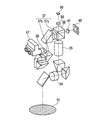
図12は、本実施例にかかる手術用顕微鏡の構成を示す部分断面図であり、顕微鏡全体の概略構成を示すものである。
本実施例の手術用顕微鏡は、鏡体部ハウジング62と、画像系ハウジング63とからなっている。画像系ハウジング63は、画像を表示するLCD64と、画像投影光学系65と、LCD64から射出した光を画像投影光学系65へ導くためのミラー66を内蔵している。
画像投影光学系65は、鏡体部ハウジング62内に配置されている手術用顕微鏡光学系の一部である図示しないビームスプリッターにLCD64からの光束をアフォーカル光束として入射させ、顕微鏡画像にLCD64に表示された画像を重ね合わせている。また、LCD64,画像投影光学系65,ミラー66を内蔵する画像系ハウジング63は、鏡体部ハウジング62に対し、着脱可能な構成となっている。
以上のような構成を備えた本実施例の手術用顕微鏡によれば、観察像の重ね合わせを必要としない観察者に対し、従来の手術用顕微鏡本体部を用いて通常の顕微鏡観察を提供することができる。
【0045】
第2実施例
図13は、本実施例にかかる手術用顕微鏡の光学系の構成を示す概略図である。本実施例の手術用顕微鏡は、第2参考例に示した手術用顕微鏡において、双眼鏡筒光学系39に代えて、双眼鏡筒ハウジング67を備えたものである。
【0046】
図14(a)は双眼鏡筒ハウジング67の外観図、同図(b)は双眼鏡筒ハウジング67の内部構成を示す光軸に沿う断面図である。
この双眼鏡筒ハウジング67は、内部に、1対のLCD68と、1対の画像投影光学系69と、結像レンズ70aと接眼レンズ70aとからなる1対の双眼鏡筒光学系70と、これらの間に配置されたミラー,プリズム等の反射部材を備えている。
【0047】
ここで、本実施例の手術用顕微鏡において、LCD68および画像投影光学系69は、図13に示したLCD40,画像投影光学系41とは役割が異なる。すなわち、双眼鏡筒光学系70の結像レンズ70aが結像する顕微鏡画像と重なり合って見えないように、その近傍にLCD68上に表示した画像を画像投影光学系69により投影し、結像している(図4に示した構成と同様である)。これにより、観察者は双眼鏡筒光学系70の接眼レンズ70bを介して双方の像を観察できる。
なお、前記顕微鏡画像には、双眼鏡筒ハウジング67外に配置した画像投影光学系41およびビームスプリッター58によってLCD40上に表示した画像が入れ込まれており、LCD40上に表示された像が前記顕微鏡画像に重なって見えるようになっている。
また、このとき、図8に示したナビゲーションシステム52を併用すれば、LCD40上にかかるナビゲーションシステム52が作成する画像を表示することができ、この画像を前記顕微鏡画像に重ねて表示することができる。
【0048】
この構成であると、図15に示すように、顕微鏡画像と重ねて表示すると互いにスポイルしてしまうような精密で情報量の多いCT/MR画像を多用した画像71は顕微鏡画像とは重なり合って見えないように、また、ナビゲーションシステム52により作成された、マーキングや記号のように情報量が少なく、互いにスポイルしないような画像71は顕微鏡画像と重なり合って見えるように調整することができる。
このように、本実施例の手術用顕微鏡では、観察者に有用である多様の画像を、その画像の性質に合わせて顕微鏡画像と共に観察者に提供することができる。
【0049】
第4参考例
図16は、本参考例にかかる手術用顕微鏡の光学系の構成を示す概略図である。
本参考例の手術用顕微鏡は、対物レンズ34,変倍レンズ35,液晶ミラー73,前群37aと後群37bからなるリレーレンズ37,およびこれらの間に介在されたミラー,プリズム等の複数の反射部材からなる単眼光学系と、左右光路入替え光学系としての偏角ダハプリズム38と、右眼用,左眼用の双眼光学系を有する双眼鏡筒光学系39を備えている。液晶ミラー73は、電圧を印加すると光の反射率および透過率を変化させることができ、これは液晶ミラー73の近傍に配置された電源装置74により可能になっている。
さらに、本参考例の手術用顕微鏡は、小型のLCD40を備え、画像投影光学系41により、LCD40からの光束をアフォーカル光束とし、液晶ミラー73へ導くようになっている。
【0050】
以上のように構成された本参考例の手術用顕微鏡では、被観察物体10から射出される光束を、対物レンズ34,変倍レンズ35,液晶ミラー73,リレーレンズ37を備えた単眼光学系を通過させ、偏角ダハプリズム38へ導く。この偏角ダハプリズム38は自身を通過する光束を偏角させ、倒立像を形成する作用を有している。したがって、被観察物体10からの光束をこの偏角ダハプリズム38を介在させて双眼鏡筒光学系39へ導くことにより、観察者の右眼に入射すべき光束は右眼に、左眼に入射すべき光束は左眼に入射させることができ、観察者に被観察物体10の正立した立体像を供給することができる。
同時に、LCD40から射出する光束も、画像投影光学系41により液晶ミラー73へ導かれ、被観察物体10からの光束が導かれる光路中へ導入される。よって、観察者は、LCD40上に表示された画像情報と被観察物体10の顕微鏡画像とを重ね合わせた状態で観察できるようになる。
【0051】
また、本参考例の手術用顕微鏡においても、図8に示したようなナビゲーションシステム52と併用することは可能である。この場合、ナビゲーションシステム52が作成する画像情報をLCD40に表示することにより、観察者は被観察物体10の顕微鏡画像とナビゲーションシステム52が作成する画像情報を重ね合わせた状態で同時に観察することが可能になる(図9を参照)。
【0052】
このように本参考例の手術用顕微鏡においても、ナビゲーションシステムを併用することにより、観察者は顕微鏡画像を見ながらにして、手術に有用な情報を得ることができ、手術の効率を大幅に向上させることができる。
しかも、本参考例の手術用顕微鏡において、これらの機能を液晶ミラー73やLCD40、画像投影光学系41をそれぞれ1つずつ搭載することで実現できるため、手術用顕微鏡鏡体部の大型重量化を防ぐことができ、良好な作業性をもたらすナビゲーションシステムと併用するのに好適な手術用顕微鏡を提供することができる。
【0053】
さらに、本参考例では、観察者が液晶ミラー73にかける電圧を任意に変更できる構成となっており、観察者は液晶ミラー73における光の反射率および透過率を任意に変えることで、顕微鏡画像と重なって表示される画像情報の濃淡を任意に変更することができる。
なお、本参考例の手術用顕微鏡に用いる液晶ミラー73は、文献「Hikmet&Kemperman Nature vol 392 pp476 2 April 1998 」に記載されているものである。
【0054】
また、本参考例ではLCD40に表示させる画像としてナビゲーションシステム52が作成する画像を表示させたが、紳経モニターや、手術に有用な数値データを表示させ、顕微鏡画像に重ね合わせても同様に手術の効率を向上させることができる。
また、本参考例では、画像表示手段としてLCD40を用いたが、これに代えてCRTやプラズマディスプレイ等を用いることも可能である。
【0058】
【発明の効果】
上述のように、本発明によれば、顕微鏡画像とモニターに表示される画像情報とを重ね合わせた像を観察,撮像でき、且つ、顕微鏡画像の明るさの低下や、顕微鏡鏡体部の大型重量化,被観察物体から観察者のアイポイントまでの距離の増加等のない、作業性の優れた実体顕微鏡を提供することができる。
【図面の簡単な説明】
【図1】 本発明の参考例にかかる実体顕微鏡の概略構成を示す光軸に沿う断面図である。
【図2】 図1に示した実体顕微鏡の他の一例を示す図である。
【図3】 本発明にかかる実体顕微鏡の概略構成を示す光軸に沿う断面図である。
【図4】 図3に示した実体顕微鏡の双眼鏡筒ハウジング21の内部構成を説明するための図である。
【図5】 図3に示した実体顕微鏡により得られる観察像を示す図である。
【図6】 本発明の他の参考例にかかる実体顕微鏡の概略構成を示す光軸に沿う断面図である。
【図7】 第1参考例にかかる手術用顕微鏡の光学系の構成を示す概略図である。
【図8】 第1参考例の手術用顕微鏡をナビゲーションシステムと併用する場合の一例を示す図である。
【図9】 (a)は腫瘍の断面図である。(b)は図8に示したシステムにより得られる観察像を示す図である。
【図10】 第2参考例にかかる手術用顕微鏡の光学系の構成を示す概略図である。
【図11】 第3参考例にかかる手術用顕微鏡の光学系の構成を示す概略図である。
【図12】 第1実施例にかかる手術用顕微鏡の構成を示す概略図である。
【図13】 第2実施例にかかる手術用顕微鏡の光学系の構成を示す概略図である。
【図14】 (a)は図13に示した双眼鏡筒ハウジング67の外観図である。(b)は図13に示した双眼鏡筒ハウジング67の内部構成を示す光軸に沿う断面図である。
【図15】 第2実施例の実体顕微鏡により得られる観察像を示す図である。
【図16】 第4参考例にかかる手術用顕微鏡の光学系の構成を示す概略図である。
【図17】 従来の実体顕微鏡の概略構成を示す図である。
【符号の説明】
1,42 手術用顕微鏡
2,19 光路分割手段
3,15 観察光路
4,30 撮影光路
5,16,31 光路合成手段
6,13,22 画像表示手段
7 光路
8 双眼光学系
10 被観察物体
11,34 対物レンズ
12,35 変倍レンズ
14,23,41,65,69 画像投影光学系
17 観察者
18,20,25,39,70 双眼鏡筒光学系
21,67 双眼鏡筒ハウジング
24 プリズム
25a,70a 結像レンズ
25b,70b 接眼レンズ
26 顕微鏡画像
27 顕微鏡画像26の近傍
28,29,71,72 画像
32,59 撮影光学系
33 撮影素子
36,58,61 ビームスプリッター
37 リレーレンズ
37a 前群
37b 後群
38 偏角ダハプリズム
40,64,68 LCD
43,50 ライトガイド
44,51 光源
45,47 ケーブル
46 カメラコントロールユニット
48 カメラユニット
49 内視鏡本体
52 ナビゲーションシステム
53 カメラアレイ
54 コンピューター
55 手術用顕微鏡42による像
56 手術用顕微鏡42による像で表面に露出して見える腫瘍
57 ナビゲーションシステム52により作成された腫瘍の露出していない部分の実質的な大きさと数値データを表した画像情報
60 CCD
62 鏡体部ハウジング
63 画像系ハウジング
66 ミラー
73 液晶ミラー
74 電源装置[0001]
BACKGROUND OF THE INVENTION
The present invention is a stereomicroscope that can display various different image information such as a microscope image and a monitor image in an observation field of view, and is particularly suitable when a surgical operation support apparatus such as a navigation system is used in combination. The present invention relates to a surgical microscope.
[0002]
[Prior art]
Stereo microscopes such as surgical microscopes have been used for surgical operations such as neurosurgery, otolaryngology, ophthalmology, etc., and have an important role such as improving the efficiency of surgery by observing the operation area. Plays.
Furthermore, in recent years, in order to perform surgery with less invasiveness, surgical microscopes have taken medical images such as CT and MRI around the surgical site before surgery, and integrated these images with a computer to process the tumor site. It is used in combination with a surgical operation support device for confirming the position and range, so-called navigation system.
By linking this navigation system and a surgical microscope, information such as how large and how large a tumor is at a certain millimeter and a distance from the position observed by the surgeon can be provided as a computer image.
Furthermore, at present, a technology has been developed that can display the range of a tumor directly on an optical observation image of a surgical microscope.
[0003]
As a technique for superimposing and displaying such a surgical microscope image and image information other than the surgical microscope, one disclosed in Japanese Patent Laid-Open No. 5-215971 is known.
FIG. 17 is a diagram showing a configuration of a surgical microscope disclosed in this publication. The surgical microscope 1 shown here is provided with an optical path dividing means 2, and the optical path dividing means 2 divides the observation
Therefore, by using this surgical microscope 1, the operator can observe the microscope image and the image displayed on the image display means 6 in an overlapping manner. For example, while observing the microscope image, Information useful for surgery such as the reach to the tumor can be obtained directly from the microscope image.
[0004]
However, this surgical microscope 1 is provided with the optical path synthesis means 5 for superimposing the observation
Further, in the surgical microscope 1, when it is possible to superimpose images with both eyes of the observer, the light beams emitted from the optical path synthesis unit 5, the image display unit 6, and the image display unit 6 are converted into the optical path synthesis unit. One pair of optical systems to be incident on the optical system 5 must be arranged, which leads to an increase in size and weight of the surgical microscope body. Furthermore, in this case, since the optical path combining means 5 is arranged so as to be stacked on the microscope observation optical path, the distance from the observed object to the observer's eye point becomes long.
[0005]
[Problems to be solved by the invention]
In a surgical microscope, in order to improve workability, not only ensuring a sufficiently bright microscope image, but also a smaller and lighter surgical microscope body, from the object to be observed to the observer's eyepoint It is an indispensable condition to make the distance as close as possible to the state without using a surgical microscope.
However, these essential conditions cannot be obtained from the technique disclosed in Japanese Patent Laid-Open No. 5-215971.
[0006]
The present invention has been made in view of the above-described problems of the prior art, and an object of the present invention is to be displayed on a microscope image and a monitor by a viewer with both eyes, or with a TV photographing device or a photographing device. The image can be observed and captured with the image information, and the brightness of the microscope image is reduced, the microscope body is enlarged, the distance from the observed object to the observer's eye point An object of the present invention is to provide a stereomicroscope that is excellent in workability without an increase in the amount of movement.
[0007]
[Means for Solving the Problems]
In order to achieve the above object, the present invention has the following features.
[0009]
The stereomicroscope of the present invention isStandingBody viewIn a stereomicroscope with an optical system, the light beam from an object is received.The luminous fluxIs an afocal light beam and receives the light beam from the objective optical system.Sudden changeDoubleI doA monocular optical system composed of one variable magnification optical system, and at least one binocular tube optical system that receives a light beam from the monocular optical system and guides it to the left and right eyes of an observer to form a pair of observation images. Comprising one optical path synthesis means in the monocular optical system,TheA light beam emitted from an image displayed on one image display unit arranged in the vicinity of the stereoscopic observation optical system is incident on one optical path synthesis unit via an image projection optical system, and the image display is performed on the observation optical path. The light beam from the means is separated, and at least one pair of image display means separate from the binocular tube optical system, the image display means, and the image projection optical system in the housing of the binocular tube optical system And an image projection optical system.
[0011]
DETAILED DESCRIPTION OF THE INVENTION
FIG. 1 illustrates the present invention.Reference exampleIt is sectional drawing which follows the optical axis which shows schematic structure of the stereoscopic microscope concerning.
The stereomicroscope includes an
[0012]
The stereomicroscope shown in FIG. 1 does not need to arrange a pair of optical path dividing means, an image projection optical system, and an image display means in the left and right observation light paths as in the prior art, and has only one image display means 13 and one image display means. The light beam from the image projection
In addition, it is good to display the image information especially by a navigation system, and the image useful for another operation on the image display means 13.
[0013]
Further, as shown in FIG. 2, the stereomicroscope shown in FIG. 1 further includes an optical
Furthermore, by increasing the binocular tube optical system in the same manner, it is possible to simultaneously guide images obtained by superimposing image information other than the microscope image on the microscope images to both eyes of a plurality of observers.
[0014]
Figure 3 shows theClearlyIt is sectional drawing which follows the optical axis which shows schematic structure of this stereomicroscope.
In this stereomicroscope, instead of the binocular tube
The
The image displayed on the
[0015]
With such a configuration, for example, as shown in FIG. 5, a precise and high-amount of
[0016]
FIG. 6 illustrates the present invention.Other reference examplesIt is sectional drawing which follows the optical axis which shows schematic structure of the stereoscopic microscope concerning. This stereomicroscope includes an
[0017]
In the stereomicroscope shown here, when an image such as a tumor range marking is displayed on the image display means 13, the light beam from the image display means 13 is divided into the observation
Furthermore, since the light beam from the image display means 13 is also divided into the photographing
[0018]
The stereomicroscope shown in FIG. 6 does not need to arrange a pair of optical path dividing means, an image projection optical system, and an image display means in the left and right observation optical paths as in the prior art, and leads from the observation optical path to the photographing optical path. Therefore, there is no need to arrange two optical path dividing means for dividing the light flux for the purpose and two optical path synthesizing means for dividing the light flux from the image projection optical system into the observation optical path. That is, the stereomicroscope shown in FIG. 6 splits the light beam from the image projection
Therefore, the microscope body can be reduced in size and weight, an increase in the distance from the observed
[0019]
Further, in this stereomicroscope, image information obtained by the navigation system and other images useful for surgery may be displayed on the image display means 13. Further, similarly to the one shown in FIG. 2, an optical path dividing means is further arranged in the observation
[0020]
Also,ThisIn the stereomicroscope, the optical path synthesizing means 16 and 31 may be disposed between the
[0021]
Also,ThisThe stereomicroscope has a pair of image display means and a light flux from the image display means in the vicinity of the stereoscopic observation optical system (binocular tube optical system 18) separately from the image display means 13 and the image projection
With this configuration, when it is inappropriate to superimpose and observe the microscope image of the object to be observed 10 and the image displayed on the image display means 13, not the image display means 13 but the image display means in the unit. By displaying the image on the screen, the microscope image of the object to be observed 10 and the image displayed on the image display means in the unit can be observed independently..
[0022]
Hereinafter, the present invention will be described in more detail based on the illustrated embodiments. The following examples all show examples of surgical microscopes.
[0023]
First reference example
Figure 7 shows the bookReference exampleIt is the schematic which shows the structure of the optical system of the surgical microscope concerning.
BookReference exampleThe surgical microscope includes an
[0024]
Book configured as aboveReference exampleIn this surgical microscope, the light beam emitted from the object to be observed 10 passes through a monocular optical system including an
At the same time, the light beam emitted from the
[0025]
Then bookReference exampleFIG. 8 shows an example in the case of using the surgical microscope together with the navigation system.
[0026]
First, bookReference exampleA light source 44 is connected to the surgical microscope 42 via a light guide 43. The surgical microscope 42 is connected to the
[0027]
Further, the
On the other hand, software for executing navigation is incorporated in the computer 54. For example, a CT image or an MRI image is displayed in advance, or three-dimensional information of an object to be observed created based on these images and a camera array 53 are used. The detected position information is compared to provide the observer with various information necessary for the operation such as information on the current operation position and the state of the body that cannot be seen with the eyes.
[0028]
As shown here, when the surgical microscope 42 and the
[0029]
Like thisReference exampleBy using the surgical microscope 42 and the
[0030]
Moreover, the bookReference exampleIn this surgical microscope, an image guided to both eyes of the observer can be formed by mounting one
[0031]
BookReference exampleIn the above, an example in which an image created by the
Also bookReference exampleIn this embodiment, the
[0032]
Second reference example
Figure 10 shows the bookReference exampleIt is the schematic which shows the structure of the optical system of the surgical microscope concerning.
BookReference exampleThe surgical microscope includes an
[0033]
Book configured as aboveReference exampleIn this surgical microscope, the light beam emitted from the object to be observed 10 passes through a monocular optical system including the
At the same time, the light beam emitted from the
[0034]
BookReference exampleIn the surgical microscope of FIG. 8, as shown in FIG.Reference exampleAs in the case of the surgical microscope shown in FIG. 4, if the image information created by the
[0035]
Book like thisReference exampleIn this surgical microscope, by using the navigation system in combination, the observer can obtain information useful for the surgery while looking at the microscope image, and the efficiency of the surgery can be greatly improved.
Also bookReference exampleIn this surgical microscope, since the superimposed observation image can be taken with the
[0036]
Moreover, the bookReference exampleIn this surgical microscope, these functions can be realized by installing each of the
[0037]
BookReference exampleIn the above example, the image generated by the
Also bookReference exampleIn this embodiment, the
[0038]
Third reference example
Figure 11 shows the bookReference exampleIt is the schematic which shows the structure of the optical system of the surgical microscope concerning.
BookReference exampleThe surgical microscope includes an
[0039]
Book configured as aboveReference exampleIn this surgical microscope, the light beam emitted from the object to be observed 10 is passed through a monocular optical system including an
At the same time, the light beam emitted from the
[0040]
Also bookReference exampleIn the surgical microscope of FIG. 8, as shown in FIG.Reference exampleAs in the case of the surgical microscope shown in FIG. 4, if the image information created by the
[0041]
Book like thisReference exampleIn this surgical microscope, by using the navigation system in combination, the observer can obtain information useful for the surgery while looking at the microscope image, and the efficiency of the surgery can be greatly improved.
Moreover, the bookReference exampleIn this surgical microscope, these functions can be realized by mounting the
[0042]
Also bookReference exampleIn the stereomicroscope, the
[0043]
BookReference exampleIn the above example, the image generated by the
Also bookReference exampleIn this surgical microscope, the
[0044]
First embodiment
FIG. 12 is a partial cross-sectional view showing the configuration of the surgical microscope according to the present embodiment, and shows the schematic configuration of the entire microscope.
The surgical microscope according to the present embodiment includes a
The image projection
According to the surgical microscope of the present embodiment having the above-described configuration, a normal microscope observation is provided to an observer who does not need to superimpose observation images using a conventional surgical microscope main body. be able to.
[0045]
Second embodiment
FIG. 13 is a schematic diagram illustrating the configuration of the optical system of the surgical microscope according to the present example. The surgical microscope of this example isSecond reference exampleThe surgical microscope shown in FIG. 6 is provided with a
[0046]
14A is an external view of the
The
[0047]
Here, in the surgical microscope of this embodiment, the
The image displayed on the
At this time, if the
[0048]
With this configuration, as shown in FIG. 15, an
As described above, in the surgical microscope according to the present embodiment, various images useful for the observer can be provided to the observer together with the microscopic image according to the properties of the image.
[0049]
Fourth reference example
Figure 16 shows the bookReference exampleIt is the schematic which shows the structure of the optical system of the surgical microscope concerning.
BookReference exampleThe surgical microscope includes an
In addition, bookReference exampleThe surgical microscope includes a
[0050]
Book configured as aboveReference exampleIn this surgical microscope, the light beam emitted from the object to be observed 10 passes through a monocular optical system including the
At the same time, the light beam emitted from the
[0051]
Also bookReference exampleThe surgical microscope of FIG. 5 can also be used in combination with the
[0052]
Book like thisReference exampleIn this surgical microscope, by using the navigation system in combination, the observer can obtain information useful for the surgery while looking at the microscope image, and the efficiency of the surgery can be greatly improved.
Moreover, the bookReference exampleIn these surgical microscopes, these functions can be realized by mounting each of the
[0053]
In addition, bookReference exampleThe observer can arbitrarily change the voltage applied to the
BookReference exampleThe
[0054]
Also bookReference exampleIn this example, an image created by the
Also
[0058]
【The invention's effect】
As described above, according to the present invention, an image obtained by superimposing a microscope image and image information displayed on a monitor can be observed and picked up, and the brightness of the microscope image is reduced or the size of the microscope body is increased. It is possible to provide a stereomicroscope having excellent workability without increasing the weight, increasing the distance from the object to be observed to the eye point of the observer, and the like.
[Brief description of the drawings]
[Figure 1]Reference example of the present inventionIt is sectional drawing which follows the optical axis which shows schematic structure of the stereoscopic microscope concerning.
FIG. 2 is a diagram showing another example of the stereomicroscope shown in FIG. 1;
[Fig. 3]The present inventionIt is sectional drawing which follows the optical axis which shows schematic structure of the stereoscopic microscope concerning.
4 is a view for explaining an internal configuration of a
5 is a diagram showing an observation image obtained by the stereomicroscope shown in FIG. 3. FIG.
[Fig. 6]Other reference examples of the present inventionIt is sectional drawing which follows the optical axis which shows schematic structure of the stereoscopic microscope concerning.
[Fig. 7]First reference exampleIt is the schematic which shows the structure of the optical system of the surgical microscope concerning.
[Fig. 8]First reference exampleIt is a figure which shows an example in the case of using together the operation microscope of this with a navigation system.
FIG. 9A is a cross-sectional view of a tumor. (B) is a figure which shows the observation image obtained by the system shown in FIG.
FIG. 10Second reference exampleIt is the schematic which shows the structure of the optical system of the surgical microscope concerning.
FIG. 11Third reference exampleIt is the schematic which shows the structure of the optical system of the surgical microscope concerning.
FIG.First embodimentIt is the schematic which shows the structure of the surgical microscope concerning.
FIG. 13Second embodimentIt is the schematic which shows the structure of the optical system of the surgical microscope concerning.
FIG. 14A is an external view of the
FIG. 15Second embodimentIt is a figure which shows the observation image obtained with no stereo microscope.
FIG. 16Fourth reference exampleIt is the schematic which shows the structure of the optical system of the surgical microscope concerning.
FIG. 17 is a diagram showing a schematic configuration of a conventional stereomicroscope.
[Explanation of symbols]
1,42 Surgical microscope
2,19 Optical path dividing means
3,15 Observation optical path
4,30 Shooting optical path
5, 16, 31 Optical path synthesis means
6, 13, 22 Image display means
7 Light path
8 Binocular optics
10 Object to be observed
11, 34 Objective lens
12, 35 zoom lens
14, 23, 41, 65, 69 Image projection optical system
17 Observer
18, 20, 25, 39, 70 Binocular tube optical system
21, 67 Binocular tube housing
24 prism
25a, 70a Imaging lens
25b, 70b eyepiece
26 Microscopic image
27 Near the
28, 29, 71, 72 images
32,59 Photography optical system
33 Image sensor
36, 58, 61 Beam splitter
37 Relay lens
37a front group
37b Rear group
38 Deflection prism
40, 64, 68 LCD
43, 50 Light guide
44, 51 Light source
45, 47 cable
46 Camera control unit
48 Camera unit
49 Endoscope body
52 Navigation system
53 Camera Array
54 Computer
55 Image from surgical microscope 42
56 Tumor that appears exposed on the surface with an image taken by the surgical microscope 42
57 Image information representing the substantial size and numerical data of the unexposed portion of the tumor created by the
60 CCD
62 Mirror body housing
63 Image system housing
66 Mirror
73 Liquid crystal mirror
74 Power supply
Claims (1)
物体からの光束を受け該光束をアフォーカル光束にする1つの対物光学系と該対物光学系からの光束を受け変倍を行う1つの変倍光学系とからなる単眼光学系と、該単眼光学系からの光束を受け観察者の左右の眼に導いて1対の観察像を結像する少なくとも1つの双眼鏡筒光学系とを備え、
前記単眼光学系中に1つの光路合成手段を配置し、該1つの光路合成手段に対し、前記立体観察光学系の近傍に配置した1つの画像表示手段上に表示される画像から射出する光束を画像投影光学系を介して入射させ、観察光路に前記画像表示手段からの光束を分け入れるようにすると共に、
前記双眼鏡筒光学系のハウジング内に、前記双眼鏡筒光学系,前記画像表示手段及び画像投影光学系とは別体の、少なくとも1対の画像表示手段と画像投影光学系を配置したことを特徴とする実体顕微鏡。In a stereomicroscope having a stereoscopic observation optical system,
A monocular optical system including a single objective optical system that receives a light beam from an object and converts the light beam into an afocal light beam, and a variable magnification optical system that receives the light beam from the objective optical system and performs zooming; And at least one binocular tube optical system for receiving a light beam from the system and guiding it to the left and right eyes of the observer to form a pair of observation images,
One optical path synthesis unit is arranged in the monocular optical system, and a light beam emitted from an image displayed on one image display unit arranged in the vicinity of the stereoscopic observation optical system is emitted to the one optical path synthesis unit. Injecting through an image projection optical system, so as to separate the light beam from the image display means into the observation optical path,
In the binocular tube optical system housing, at least one pair of image display means and image projection optical system separate from the binocular tube optical system, the image display means, and the image projection optical system are arranged. Stereo microscope to do.
Priority Applications (1)
| Application Number | Priority Date | Filing Date | Title |
|---|---|---|---|
| JP01465999A JP4426662B2 (en) | 1999-01-22 | 1999-01-22 | Stereo microscope |
Applications Claiming Priority (1)
| Application Number | Priority Date | Filing Date | Title |
|---|---|---|---|
| JP01465999A JP4426662B2 (en) | 1999-01-22 | 1999-01-22 | Stereo microscope |
Publications (3)
| Publication Number | Publication Date |
|---|---|
| JP2000214388A JP2000214388A (en) | 2000-08-04 |
| JP2000214388A5 JP2000214388A5 (en) | 2005-10-20 |
| JP4426662B2 true JP4426662B2 (en) | 2010-03-03 |
Family
ID=11867352
Family Applications (1)
| Application Number | Title | Priority Date | Filing Date |
|---|---|---|---|
| JP01465999A Expired - Fee Related JP4426662B2 (en) | 1999-01-22 | 1999-01-22 | Stereo microscope |
Country Status (1)
| Country | Link |
|---|---|
| JP (1) | JP4426662B2 (en) |
Families Citing this family (6)
| Publication number | Priority date | Publication date | Assignee | Title |
|---|---|---|---|---|
| DE102006003575A1 (en) * | 2006-01-25 | 2007-07-26 | Carl Zeiss Surgical Gmbh | Optical system e.g. operation microscope, for e.g. viewing tumor in brain, has imaging layer formed such that high optical resolution of object to be viewed is provided, where resolution is higher than resolution of another layer |
| DE102009019575A1 (en) | 2009-04-28 | 2010-11-11 | Carl Zeiss Surgical Gmbh | Stereoscopic optical viewing device has multi-channel optics with two stereoscopic optical channels having optical channels, where afocal optical interface device is arranged before optical inlet end of multi-channel optics |
| KR101379482B1 (en) * | 2012-08-08 | 2014-04-01 | (주)이오시스템 | Complex eyepiece |
| WO2019059314A1 (en) * | 2017-09-22 | 2019-03-28 | 株式会社ニコン | Image display device and image display system |
| WO2019220856A1 (en) | 2018-05-14 | 2019-11-21 | 株式会社ニコン | Image display device, image display system, image display method, and image processing program |
| JP7150866B2 (en) * | 2018-09-28 | 2022-10-11 | 株式会社エビデント | Microscope system, projection unit, and image projection method |
-
1999
- 1999-01-22 JP JP01465999A patent/JP4426662B2/en not_active Expired - Fee Related
Also Published As
| Publication number | Publication date |
|---|---|
| JP2000214388A (en) | 2000-08-04 |
Similar Documents
| Publication | Publication Date | Title |
|---|---|---|
| JP7073450B2 (en) | Generation of observation image of the target area | |
| CA3059237C (en) | Stereoscopic visualization camera and platform | |
| US6473229B2 (en) | Stereomicroscope | |
| EP2903551B1 (en) | Digital system for surgical video capturing and display | |
| JP4721981B2 (en) | Stereo microscope | |
| US20040263613A1 (en) | Stereo-observation system | |
| US10838189B2 (en) | Operating microscope having an image sensor and a display, and method for operating an operating microscope | |
| JP3625906B2 (en) | Surgical microscope equipment | |
| US7688503B2 (en) | Microscopy system and microscopy method for plural observers | |
| US8477416B2 (en) | Stereomicroscope | |
| JP2004109554A (en) | Photographing device for stereoscopic microscope | |
| JP4508569B2 (en) | Binocular stereoscopic observation device, electronic image stereoscopic microscope, electronic image stereoscopic observation device, electronic image observation device | |
| JPH11318936A (en) | Microscopic device for operation | |
| JP4426662B2 (en) | Stereo microscope | |
| JP2002315721A (en) | Stereoscopic system for enucleation of cancer tissue | |
| US20230120611A1 (en) | Stereoscopic camera with fluorescence strobing based visualization | |
| JP2001075011A (en) | Stereoscopic microscope | |
| JP3619858B2 (en) | Stereoscopic microscope | |
| JP2009163200A (en) | Stereomicroscope | |
| JP2000338416A (en) | Stereoscopic view microscope | |
| JP2001108905A (en) | Stereoscopic microscope | |
| JP2005070809A (en) | Stereoscopic microscope | |
| JP2009095598A (en) | Head-mounted binocular magnifying glass device | |
| JPH06277185A (en) | Ophthalmic observation and photographing apparatus | |
| WO2019225693A1 (en) | Surgical observation system |
Legal Events
| Date | Code | Title | Description |
|---|---|---|---|
| A521 | Written amendment |
Free format text: JAPANESE INTERMEDIATE CODE: A523 Effective date: 20050621 |
|
| A621 | Written request for application examination |
Free format text: JAPANESE INTERMEDIATE CODE: A621 Effective date: 20050621 |
|
| A131 | Notification of reasons for refusal |
Free format text: JAPANESE INTERMEDIATE CODE: A131 Effective date: 20080715 |
|
| A521 | Written amendment |
Free format text: JAPANESE INTERMEDIATE CODE: A523 Effective date: 20080912 |
|
| A131 | Notification of reasons for refusal |
Free format text: JAPANESE INTERMEDIATE CODE: A131 Effective date: 20090825 |
|
| A521 | Written amendment |
Free format text: JAPANESE INTERMEDIATE CODE: A523 Effective date: 20091021 |
|
| TRDD | Decision of grant or rejection written | ||
| A01 | Written decision to grant a patent or to grant a registration (utility model) |
Free format text: JAPANESE INTERMEDIATE CODE: A01 Effective date: 20091117 |
|
| A01 | Written decision to grant a patent or to grant a registration (utility model) |
Free format text: JAPANESE INTERMEDIATE CODE: A01 |
|
| A61 | First payment of annual fees (during grant procedure) |
Free format text: JAPANESE INTERMEDIATE CODE: A61 Effective date: 20091211 |
|
| FPAY | Renewal fee payment (event date is renewal date of database) |
Free format text: PAYMENT UNTIL: 20121218 Year of fee payment: 3 |
|
| FPAY | Renewal fee payment (event date is renewal date of database) |
Free format text: PAYMENT UNTIL: 20131218 Year of fee payment: 4 |
|
| LAPS | Cancellation because of no payment of annual fees |