JP4420097B2 - Injection abnormality detection device and fuel injection system - Google Patents
Injection abnormality detection device and fuel injection system Download PDFInfo
- Publication number
- JP4420097B2 JP4420097B2 JP2007258512A JP2007258512A JP4420097B2 JP 4420097 B2 JP4420097 B2 JP 4420097B2 JP 2007258512 A JP2007258512 A JP 2007258512A JP 2007258512 A JP2007258512 A JP 2007258512A JP 4420097 B2 JP4420097 B2 JP 4420097B2
- Authority
- JP
- Japan
- Prior art keywords
- injection
- fuel
- pressure
- abnormality
- detected
- Prior art date
- Legal status (The legal status is an assumption and is not a legal conclusion. Google has not performed a legal analysis and makes no representation as to the accuracy of the status listed.)
- Active
Links
Images


Classifications
-
- F—MECHANICAL ENGINEERING; LIGHTING; HEATING; WEAPONS; BLASTING
- F02—COMBUSTION ENGINES; HOT-GAS OR COMBUSTION-PRODUCT ENGINE PLANTS
- F02D—CONTROLLING COMBUSTION ENGINES
- F02D41/00—Electrical control of supply of combustible mixture or its constituents
- F02D41/22—Safety or indicating devices for abnormal conditions
-
- F—MECHANICAL ENGINEERING; LIGHTING; HEATING; WEAPONS; BLASTING
- F02—COMBUSTION ENGINES; HOT-GAS OR COMBUSTION-PRODUCT ENGINE PLANTS
- F02D—CONTROLLING COMBUSTION ENGINES
- F02D41/00—Electrical control of supply of combustible mixture or its constituents
- F02D41/30—Controlling fuel injection
- F02D41/38—Controlling fuel injection of the high pressure type
- F02D41/3809—Common rail control systems
-
- F—MECHANICAL ENGINEERING; LIGHTING; HEATING; WEAPONS; BLASTING
- F02—COMBUSTION ENGINES; HOT-GAS OR COMBUSTION-PRODUCT ENGINE PLANTS
- F02M—SUPPLYING COMBUSTION ENGINES IN GENERAL WITH COMBUSTIBLE MIXTURES OR CONSTITUENTS THEREOF
- F02M57/00—Fuel-injectors combined or associated with other devices
- F02M57/005—Fuel-injectors combined or associated with other devices the devices being sensors
-
- F—MECHANICAL ENGINEERING; LIGHTING; HEATING; WEAPONS; BLASTING
- F02—COMBUSTION ENGINES; HOT-GAS OR COMBUSTION-PRODUCT ENGINE PLANTS
- F02D—CONTROLLING COMBUSTION ENGINES
- F02D41/00—Electrical control of supply of combustible mixture or its constituents
- F02D41/22—Safety or indicating devices for abnormal conditions
- F02D2041/224—Diagnosis of the fuel system
- F02D2041/225—Leakage detection
-
- F—MECHANICAL ENGINEERING; LIGHTING; HEATING; WEAPONS; BLASTING
- F02—COMBUSTION ENGINES; HOT-GAS OR COMBUSTION-PRODUCT ENGINE PLANTS
- F02D—CONTROLLING COMBUSTION ENGINES
- F02D2200/00—Input parameters for engine control
- F02D2200/02—Input parameters for engine control the parameters being related to the engine
- F02D2200/06—Fuel or fuel supply system parameters
- F02D2200/0602—Fuel pressure
Landscapes
- Engineering & Computer Science (AREA)
- Chemical & Material Sciences (AREA)
- Combustion & Propulsion (AREA)
- Mechanical Engineering (AREA)
- General Engineering & Computer Science (AREA)
- Analytical Chemistry (AREA)
- Electrical Control Of Air Or Fuel Supplied To Internal-Combustion Engine (AREA)
- Combined Controls Of Internal Combustion Engines (AREA)
- Fuel-Injection Apparatus (AREA)
Description
本発明は、燃料噴射弁からの燃料噴射異常を検出する噴射異常検出装置及び燃料噴射システムに関する。 The present invention relates to an injection abnormality detection device and a fuel injection system that detect an abnormality in fuel injection from a fuel injection valve.
コモンレール(蓄圧容器)で蓄圧された燃料を、噴射指令信号に基づき燃料噴射弁から噴射する燃料噴射システムにおいて、燃料漏れ等の原因により噴射指令と異なる態様で燃料が噴射されてしまうことがあり、このような噴射異常状態を検出する装置が従来より知られている(特許文献1等参照)。 In a fuel injection system that injects fuel accumulated in a common rail (pressure accumulator) from a fuel injection valve based on an injection command signal, fuel may be injected in a manner different from the injection command due to causes such as fuel leakage, An apparatus for detecting such an abnormal injection state has been known (see Patent Document 1).
特許文献1記載の燃料噴射システムでは、蓄圧燃料の圧力を検出するレール圧センサをコモンレールに備えており、レール圧センサの検出圧力が目標値に近づくよう、コモンレールに燃料を圧送する燃料ポンプの作動をフィードバック制御している。なお、前記目標値は、エンジン回転速度及びエンジン負荷に基づき設定される。そして、特許文献1記載の噴射異常検出装置は、前記目標値が基準値以下となった場合に燃料漏れ異常により所望する量の燃料が噴射されていないとの噴射異常状態を検出している。
しかしながら、特許文献1記載の噴射異常検出装置は、フィードバック制御に用いる目標値に異常が生じることで噴射異常を検出するものであるため、実際の噴射状態を間接的に検出していると言える。そのため、燃料漏れ等に起因して燃料噴射量が実際に少なくなり始めてから目標値に異常が生じるまでのタイムラグが大きいので、噴射異常を即時に検出することが困難であるとともに、その検出精度も悪い。
However, it can be said that the injection abnormality detection device described in
本発明は、上記課題を解決するためになされたものであり、その目的は、噴射異常を即時に精度良く検出できるようにした噴射異常検出装置及び燃料噴射システムを提供することにある。 The present invention has been made to solve the above problems, and an object of the present invention is to provide an injection abnormality detection device and a fuel injection system that can detect an injection abnormality immediately and accurately.
以下、上記課題を解決するための手段、及びその作用効果について記載する。 Hereinafter, means for solving the above-described problems and the operation and effects thereof will be described.
<請求項1,4,7,10,13,16,19について>
請求項1,4,7,10,13,16,19記載の発明では、蓄圧容器で蓄圧された燃料を燃料噴射弁から噴射する燃料噴射システムに適用される噴射異常検出装置であって、前記蓄圧容器から前記燃料噴射弁の噴射孔に至るまでの燃料通路のうち前記蓄圧容器に対して前記噴射孔に近い側に配置され、前記噴射孔からの燃料噴射に伴い変動する燃料の圧力を検出する燃圧センサと、燃料の噴射態様を指令する噴射指令信号を前記燃料噴射弁に出力する指令信号出力手段と、前記燃圧センサの検出圧力が前記噴射指令信号から想定される範囲の変動態様で変動しているか否かを判定し、前記想定される範囲の変動態様でないと判定した場合に噴射異常が発生していると判断する噴射異常判定手段と、を備えることを特徴とする。
<About
The invention according to
ところで、燃料噴射弁の噴射孔における燃料の圧力は燃料の噴射に伴い変動する。そして、このような噴射孔での圧力変動と実際の噴射状態とは相関が強く、例えば、実噴射開始に伴い、噴射孔での圧力は下降を開始するよう変動する。本発明者らはこの点に着目しており、前記圧力変動を検出することで実際の噴射状態を詳細に検知することを検討した。しかしながら上記特許文献1記載の燃料噴射システムでは、燃圧センサ(レール圧センサ)は、蓄圧容器内の燃料圧力を検出することを目的としているため蓄圧容器に取り付けられている。そのため、噴射に伴い生じる圧力変動は蓄圧容器内で減衰してしまう。よって、こうした従来システムでは前記圧力変動を精度よく検出することは困難である。
By the way, the pressure of the fuel in the injection hole of the fuel injection valve varies as the fuel is injected. And the pressure fluctuation in such an injection hole and an actual injection state have a strong correlation, for example, the pressure in an injection hole is fluctuate | varied so that a fall may be started with an actual injection start. The present inventors paid attention to this point, and studied to detect the actual injection state in detail by detecting the pressure fluctuation. However, in the fuel injection system described in
これに対し本発明では、燃圧センサを、蓄圧容器から噴射孔に至るまでの燃料通路のうち蓄圧容器に対して噴射孔に近い側に配置しているので、噴射孔での圧力変動を蓄圧容器内で減衰する前に検出することができる。よって、噴射に伴い生じる圧力変動を精度よく検出することができるので、その検出結果を用いて実際の噴射状態を詳細に検知することができる。 On the other hand, in the present invention, the fuel pressure sensor is disposed on the side closer to the injection hole with respect to the pressure accumulation container in the fuel passage from the pressure accumulation container to the injection hole. Can be detected before decaying. Therefore, the pressure fluctuation caused by the injection can be accurately detected, and the actual injection state can be detected in detail using the detection result.
そして、このように噴射状態を詳細に検知できるよう燃圧センサを配置したことに加え、本発明では、燃圧センサの検出圧力が噴射指令信号から想定される範囲の変動態様で変動しているか否かを判定し、前記想定される範囲の変動態様でないと判定した場合に噴射異常が発生していると判断する。そのため、実際の噴射状態が燃圧センサにより直接的に検出され、その検出結果に基づき噴射異常の発生有無が判断されるので、フィードバック制御に用いる目標値に間接的に現れる異常に基づき噴射異常を判断する先述の特許文献1記載の検出装置に比べ、噴射異常を即時かつ精度良く検出できる。
In addition to arranging the fuel pressure sensor so that the injection state can be detected in detail in this way, in the present invention, whether or not the detected pressure of the fuel pressure sensor fluctuates in a variation mode assumed from the injection command signal. When it is determined that the fluctuation mode is not within the assumed range, it is determined that an injection abnormality has occurred. Therefore, the actual injection state is directly detected by the fuel pressure sensor, and the presence or absence of the injection abnormality is determined based on the detection result. Therefore, the injection abnormality is determined based on the abnormality that indirectly appears in the target value used for feedback control. Compared to the detection device described in
以降に説明する請求項1〜21記載の発明は、検出圧力の推移波形中に現れる変化と実際の噴射状態の変化との各種相関に着目してなされたものである。なお、以降の説明に用いる図5は、噴射異常が発生していない場合における噴射率(単位時間あたりに噴射される量)と燃圧センサの検出圧力の推移波形との相関を例示するタイムチャートである。また、図6〜図12では上記噴射率を模式的に例示しており、図中の実線は噴射異常が発生している時の噴射率を、図中の一点鎖線は正常噴射時の噴射率を示している。
The inventions according to
<請求項1,2について>
図5及び図6にて例示されるように、正常噴射であれば、噴射開始指令時期Isから第1所定時間T11内に噴射孔から燃料の噴射が開始され、噴射率は変化点R3にて上昇を開始する。そして、このようにR3の時点で噴射率が上昇を開始したことに伴い、燃圧センサの検出圧力は変化点P3にて下降を開始する。したがって、このような変化点R3とP3の相関に着目すれば、検出圧力の推移波形中に変化点P3が現れたことに基づき、実際に噴射開始されたことが検知できる。
<About
As illustrated in FIGS. 5 and 6, in the case of normal injection, fuel injection is started from the injection hole within the first predetermined time T11 from the injection start command timing Is, and the injection rate is changed at the change point R3. Start climbing. As the injection rate starts increasing at the time point R3 as described above, the detected pressure of the fuel pressure sensor starts decreasing at the change point P3. Therefore, if attention is paid to the correlation between the change points R3 and P3, it can be detected that the injection is actually started based on the change point P3 appearing in the transition waveform of the detected pressure.
この点を鑑み、請求項1記載の発明では、前記検出圧力の推移波形中に現れる、実噴射開始に起因した圧力下降の開始(変化点P3)を検出する噴射開始検出手段を備え、前記噴射異常判定手段は、前記噴射指令信号による噴射開始指令時期(Is)から第1所定時間(T11)内に前記圧力下降の開始が検出されなかった場合に、前記想定される範囲の変動態様でないと判定することを特徴とする。よって、噴射異常を好適に検出できる。
In view of this point, the invention according to
また、上記請求項1記載の発明によれば、噴射開始指令に反して無噴射となっている可能性が高いとの情報を取得できる。そこで請求項2記載の発明では、前記噴射異常判定手段により前記噴射異常が発生していると判断された場合に、噴射開始指令に反して無噴射となっている異常状態の可能性があるとの情報を含む異常信号を出力することを特徴とする。これによれば、噴射異常発生後の対応に前記情報を用いることができ、好適である。
Further, according to the first aspect of the present invention, it is possible to acquire information that there is a high possibility of no injection against the injection start command. Therefore, in the invention according to
<請求項3〜5について>
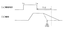
図5及び図7にて例示されるように、正常噴射であれば、噴射終了指令時期Ieから第2所定時間T12内に噴射孔からの燃料噴射が終了し、変化点R7から下降を続ける噴射率は変化点R8にて下降を終了する。そして、このようにR8の時点で噴射率が下降を終了したことに伴い、燃圧センサの検出圧力は変化点P8にて上昇を終了する。したがって、このような変化点R8とP8の相関に着目すれば、検出圧力の推移波形中に変化点P8が現れたことに基づき、実際に噴射終了したことが検知できる。
<About the claim 3-5>
As illustrated in FIGS. 5 and 7, if normal injection, the fuel injection from the injection hole ends within the second predetermined time T12 from the injection end command timing Ie, and continues to decrease from the change point R7. The rate ends at the change point R8. As the injection rate ends decreasing at the time point R8 as described above, the detected pressure of the fuel pressure sensor ends increasing at the change point P8. Therefore, paying attention to the correlation between the change points R8 and P8, it can be detected that the injection has actually ended based on the change point P8 appearing in the transition waveform of the detected pressure.
この点を鑑み、請求項3,4記載の発明では、前記検出圧力の推移波形中に現れる、実噴射終了に起因した圧力上昇の終了を検出する噴射終了検出手段を備え、前記噴射異常判定手段は、前記噴射指令信号による噴射終了指令時期から第2所定時間内に前記圧力上昇の終了が検出されなかった場合に、前記想定される範囲の変動態様でないと判定することを特徴とする。よって、噴射異常を好適に検出できる。
In view of this point, the invention according to
また、上記請求項3,4記載の発明によれば、噴射終了指令に反して噴射が継続されている可能性が高いとの情報を取得できる。そこで請求項5記載の発明では、前記噴射異常判定手段により前記噴射異常が発生していると判断された場合に、噴射終了指令に反して噴射が継続されている異常状態の可能性があるとの情報を含む異常信号を出力することを特徴とする。これによれば、噴射異常発生後の対応に前記情報を用いることができ、好適である。 Further, according to the third and fourth aspects of the invention, it is possible to acquire information that it is highly possible that the injection is continued against the injection end command. Therefore, in the invention according to claim 5, there is a possibility of an abnormal state in which the injection is continued against the injection end command when the injection abnormality determining means determines that the injection abnormality has occurred. An abnormal signal including the above information is output. According to this, the said information can be used for the response | compatibility after injection abnormality generation | occurrence | production, and it is suitable.
<請求項6〜8について>
図5及び図8にて例示されるように、正常噴射であれば、噴射終了指令時期Ieから第3所定時間T13内に、最大噴射率であった噴射率は変化点R7にて下降を開始し、当該下降開始に伴い、燃圧センサの検出圧力は変化点P7にて上昇を開始する。したがって、このような変化点R7とP7の相関に着目すれば、検出圧力の推移波形中に変化点P7が現れたことに基づき、実際に噴射率が下降を開始したことが検知できる。
<About Claims 6-8 >
As illustrated in FIG. 5 and FIG. 8, if normal injection, the injection rate that was the maximum injection rate starts decreasing at the change point R7 within the third predetermined time T13 from the injection end command timing Ie. As the descent starts, the detected pressure of the fuel pressure sensor starts increasing at the change point P7. Therefore, paying attention to the correlation between the change points R7 and P7, it can be detected that the injection rate has actually started to decrease based on the change point P7 appearing in the transition waveform of the detected pressure.
この点を鑑み、請求項6,7記載の発明では、前記検出圧力の推移波形中に現れる、噴射終了作動を開始することによる実噴射率下降開始に起因した圧力上昇の開始を検出する噴射終了作動開始検出手段を備え、前記噴射異常判定手段は、前記噴射指令信号による噴射終了指令時期から第3所定時間内に前記圧力上昇の開始が検出されなかった場合に、前記想定される範囲の変動態様でないと判定することを特徴とする。よって、噴射異常を好適に検出できる。 In view of this point, in the inventions according to claims 6 and 7 , the injection end for detecting the start of the pressure increase caused by the start of the actual injection rate lowering by starting the injection end operation, which appears in the transition waveform of the detected pressure. An operation start detecting unit, wherein the injection abnormality determining unit detects a change in the assumed range when the start of the pressure increase is not detected within a third predetermined time from the injection end command timing by the injection command signal. It is determined that it is not an aspect. Therefore, it is possible to suitably detect the injection abnormality.
また、上記請求項6,7記載の発明によれば、噴射終了指令に反して噴射率下降が開始されていない可能性が高いとの情報を取得できる。そこで請求項8記載の発明では、前記噴射異常判定手段により前記噴射異常が発生していると判断された場合に、噴射終了指令に反して噴射率下降が開始されない異常状態の可能性があるとの情報を含む異常信号を出力することを特徴とする。これによれば、噴射異常発生後の対応に前記情報を用いることができ、好適である。 Further, according to the inventions of claims 6 and 7 , it is possible to acquire information that there is a high possibility that the injection rate lowering is not started against the injection end command. Therefore, in the invention according to claim 8, there is a possibility that there is an abnormal state in which the injection rate lowering is not started against the injection end command when it is determined by the injection abnormality determining means that the injection abnormality has occurred. An abnormal signal including the above information is output. According to this, the said information can be used for the response | compatibility after injection abnormality generation | occurrence | production, It is suitable.
<請求項9〜11について>
図5及び図9にて例示されるように、噴射開始に伴い上昇した噴射率の上昇量(最大噴射率Rβ)が大きいほど、噴射開始に伴い生じる変化点P3からの検出圧力の下降量Pβは大きくなる。したがって、このような変化量RβとPβの相関に着目すれば、検出圧力の推移波形中に現れる下降量Pβに基づき実際の最大噴射率Rβを検知できる。
<About Claims 9-11 >
As illustrated in FIG. 5 and FIG. 9, as the amount of increase in the injection rate that has increased with the start of injection (maximum injection rate Rβ) increases, the amount of decrease Pβ in the detected pressure from the change point P3 that occurs with the start of injection. Becomes bigger. Therefore, if attention is paid to the correlation between the change amounts Rβ and Pβ, the actual maximum injection rate Rβ can be detected based on the decrease amount Pβ appearing in the transition waveform of the detected pressure.
この点を鑑み、請求項9,10記載の発明では、前記検出圧力の推移波形中に現れる、実噴射開始後の最大噴射率到達に起因した圧力下降の終了を検出する最大噴射率到達検出手段を備え、前記噴射異常判定手段は、前記最大噴射率到達後の第4所定時間内に前記検出圧力が所定の閾値を超えなかった場合に、前記想定される範囲の変動態様でないと判定することを特徴とする。よって、噴射異常を好適に検出できる。
In view of this point, in the inventions according to
また、上記請求項9,10記載の発明によれば、指令した最大噴射率まで噴射率が十分に高くなっていない可能性が高いとの情報を取得できる。そこで請求項11記載の発明では、前記噴射異常判定手段により前記噴射異常が発生していると判断された場合に、指令した最大噴射率まで噴射率が十分に高くなっていない異常状態の可能性があるとの情報を含む異常信号を出力することを特徴とする。これによれば、噴射異常発生後の対応に前記情報を用いることができ、好適である。
According to the invention of the claim 9 wherein can acquire information of the injection rate to the maximum injection rate command the is likely to not become sufficiently high. Therefore, in the invention according to
<請求項12〜14について>
図5及び図10にて例示されるように、噴射開始に伴い変化点R3から噴射率が上昇する際の上昇率Rαと、噴射開始に伴い生じる変化点P3から検出圧力が下降する際の下降率Pαとの相関に関し、上昇率Rαが大きく噴射率が急激に上昇するほど、下降率Pαは小さく検出圧力は急激に下降する。したがって、このような上昇率Rαと下降率Pαの相関に着目すれば、検出圧力の推移波形中に現れる下降率Pαに基づき、実際の噴射率の上昇率Rαを検知できる。
<About Claims 12-14 >
As illustrated in FIGS. 5 and 10, the rate of increase Rα when the injection rate increases from the change point R3 with the start of injection, and the decrease when the detected pressure decreases from the change point P3 that occurs with the start of injection. Regarding the correlation with the rate Pα, as the increase rate Rα is large and the injection rate increases rapidly, the decrease rate Pα decreases and the detected pressure decreases rapidly. Accordingly, if attention is paid to the correlation between the increase rate Rα and the decrease rate Pα, the actual increase rate Rα of the injection rate can be detected based on the decrease rate Pα appearing in the transition waveform of the detected pressure.
この点を鑑み、請求項12,13記載の発明では、前記検出圧力の推移波形中に現れる、実噴射開始後の噴射率上昇に起因した圧力下降の下降率を検出する噴射率上昇検出手段を備え、前記噴射異常判定手段は、前記下降率が所定の下降率より小さい場合に、前記想定される範囲の変動態様でないと判定することを特徴とする。よって、噴射異常を好適に検出できる。
In view of this point, in the inventions according to
また、上記請求項12,13記載の発明によれば、実際の噴射率の上昇率が指令した上昇率よりも低くなっている可能性が高いとの情報を取得できる。そこで請求項14記載の発明では、前記噴射異常判定手段により前記噴射異常が発生していると判断された場合に、実際の噴射率の上昇率が指令した上昇率よりも低くなっている異常状態の可能性があるとの情報を含む異常信号を出力することを特徴とする。これによれば、噴射異常発生後の対応に前記情報を用いることができ、好適である。
Further, according to the inventions of
<請求項15〜17,20,21について>
図5及び図11にて例示されるように、実噴射開始から終了までの噴射率の積分値(斜線を付した符号Sに示す部分の面積)は噴射量に相当する。そして、検出圧力の推移波形のうち実噴射開始から終了までの噴射率変化に対応する部分(変化点P3〜P8の部分)の圧力の積分値と噴射率の積分値Sとは相関があり、圧力積分値が大きいほど噴射率積分値Sは大きい。したがって、このような両積分値の相関に着目すれば、検出圧力の推移波形から算出される積分値に基づき、実際の噴射量Sを検知できる。
<About Claims 15-17 , 20 , 21 >
As illustrated in FIGS. 5 and 11, the integral value of the injection rate from the start to the end of the actual injection (the area of the portion indicated by the hatched symbol S) corresponds to the injection amount. Then, the integral value of the pressure and the integral value S of the injection rate in the portion corresponding to the change in the injection rate from the start to the end of the actual injection (the change points P3 to P8) in the transition waveform of the detected pressure are correlated, The injection rate integral value S increases as the pressure integral value increases. Therefore, when paying attention to such a correlation between both integral values, the actual injection amount S can be detected based on the integral value calculated from the transition waveform of the detected pressure.
この点を鑑み、請求項15,16記載の発明では、前記検出圧力の推移波形のうち実噴射開始から終了までの噴射率変化に対応する部分の波形について、噴射量に相当する圧力の積分値を算出する噴射量算出手段を備え、前記噴射異常判定手段は、前記噴射量算出手段により算出された噴射量が所定の下限値より少ない場合に、前記想定される範囲の変動態様でないと判定することを特徴とする。また、請求項20記載の発明では、前記噴射異常判定手段は、前記噴射量算出手段により算出された噴射量が所定の上限値より多い場合に、前記想定される範囲の変動態様でないと判定することを特徴とする。よって、噴射異常を好適に検出できる。
In view of this point, in the inventions according to claims 15 and 16 , the integrated value of the pressure corresponding to the injection amount for the waveform corresponding to the change in the injection rate from the start to the end of the actual injection in the transition waveform of the detected pressure. The injection abnormality calculating means determines that it is not a variation mode of the assumed range when the injection amount calculated by the injection amount calculating means is less than a predetermined lower limit value. It is characterized by that. In the invention according to
また、上記請求項15,16記載の発明によれば、実際の噴射量が指令した噴射量に対して過少となっている可能性が高いとの情報を取得でき、上記請求項20記載の発明によれば、実際の噴射量が指令した噴射量に対して過多となっている可能性が高いとの情報を取得できる。そこで請求項17記載の発明では、前記噴射異常判定手段により前記噴射異常が発生していると判断された場合に、実際の噴射量が指令した噴射量に対して過少となっている異常状態の可能性があるとの情報を含む異常信号を出力することを特徴とする。また、請求項21記載の発明では、実際の噴射量が指令した噴射量に対して過多となっている異常状態の可能性があるとの情報を含む異常信号を出力することを特徴とする。これらによれば、噴射異常発生後の対応に前記情報を用いることができ、好適である。
Further, according to the inventions of claims 15 and 16 , it is possible to obtain information that the actual injection amount is likely to be insufficient with respect to the commanded injection amount, and the invention of
<請求項18,19,22〜24について>
請求項18,19記載の発明では、前記蓄圧容器から前記燃料噴射弁の燃料流入口までの燃料通路には、蓄圧容器内の燃料の圧力脈動を減衰させるオリフィスが備えられており、前記燃圧センサは前記オリフィスの燃料流れ下流側に配置されていることを特徴とする。ここで、前記オリフィスの上流側に燃圧センサを配置した場合には、噴射孔での圧力変動がオリフィスにより減衰してしまった後の圧力変動を検出することとなる。これに対し上記請求項18,19記載の発明によれば、オリフィスの下流側に燃圧センサを配置するので、オリフィスにより減衰する前の状態の圧力変動を検出することができ、噴射孔での圧力変動をより的確に検出することができる。
請求項22記載の発明では、前記燃圧センサは前記燃料噴射弁に取り付けられていることを特徴とする。そのため、蓄圧容器と燃料噴射弁とを接続する配管に燃圧センサを取り付ける場合に比べて、燃圧センサの取り付け位置が燃料噴射弁の噴射孔に近い位置となる。よって、噴射孔での圧力変動が前記配管にて減衰してしまった後の圧力変動を検出する場合に比べて、噴射孔での圧力変動をより的確に検出することができる。
<About Claims 18 , 19 , 22-24 >
In the present invention, the fuel passage from the pressure accumulator vessel to the fuel inlet of the fuel injection valve is provided with an orifice for attenuating the pressure pulsation of the fuel in the pressure accumulator vessel, and the fuel pressure sensor Is arranged on the downstream side of the fuel flow of the orifice. Here, when a fuel pressure sensor is arranged on the upstream side of the orifice, the pressure fluctuation after the pressure fluctuation at the injection hole is attenuated by the orifice is detected. On the other hand, according to the inventions of
In a twenty-second aspect of the invention, the fuel pressure sensor is attached to the fuel injection valve. For this reason, the attachment position of the fuel pressure sensor is closer to the injection hole of the fuel injection valve than when the fuel pressure sensor is attached to the pipe connecting the pressure accumulating container and the fuel injection valve. Therefore, the pressure fluctuation at the injection hole can be detected more accurately as compared with the case where the pressure fluctuation after the pressure fluctuation at the injection hole is attenuated by the pipe is detected.
上述の如く燃圧センサを燃料噴射弁に取り付けるにあたり、請求項23記載の発明では前記燃料噴射弁の燃料流入口に取り付けることを特徴とし、請求項24記載の発明では、前記燃料噴射弁の内部に取り付け、前記燃料噴射弁の燃料流入口から前記噴射孔に至るまでの内部燃料通路の燃料圧力を検出することを特徴とする。
As described above, when the fuel pressure sensor is attached to the fuel injection valve, the invention according to
上述の如く燃料流入口に取り付ける場合には、燃料噴射弁の内部に取り付ける場合に比べて燃圧センサの取付構造を簡素にできる。一方、燃料噴射弁の内部に取り付ける場合には、燃料流入口に取り付ける場合に比べて燃圧センサの取り付け位置が燃料噴射弁の噴射孔に近い位置となるので、噴射孔での圧力変動をより的確に検出することができる。 In the case where the fuel pressure sensor is attached to the fuel inlet as described above, the fuel pressure sensor attachment structure can be simplified as compared with the case where the fuel pressure sensor is attached inside the fuel injection valve. On the other hand, when installed inside the fuel injection valve, the fuel pressure sensor is installed closer to the injection hole of the fuel injection valve than when installed at the fuel inlet, so that the pressure fluctuation at the injection hole is more accurately detected. Can be detected.
<請求項25について>
請求項25記載の発明では、上記噴射異常検出装置と、燃料を蓄圧する蓄圧容器、及び前記蓄圧容器で蓄圧された燃料を噴射する燃料噴射弁の少なくとも一方と、を備えることを特徴とする燃料噴射システムである。この燃料噴射システムによれば、上述の各種効果を同様に発揮することができる。
<About Claim 25 >
The invention according to
以下、本発明に係る燃料噴射装置及び燃料噴射システムを具体化した一実施形態について図面を参照しつつ説明する。なお、本実施形態の装置は、例えば4輪自動車用エンジン(内燃機関)を対象にするコモンレール式燃料噴射システムに搭載されており、ディーゼルエンジンのエンジンシリンダ内の燃焼室に直接的に高圧燃料(例えば噴射圧力「1000気圧」以上の軽油)を噴射供給(直噴供給)する際に用いられる。 DESCRIPTION OF EXEMPLARY EMBODIMENTS Hereinafter, an embodiment embodying a fuel injection device and a fuel injection system according to the invention will be described with reference to the drawings. In addition, the apparatus of this embodiment is mounted in the common rail type fuel-injection system which targets the engine (internal combustion engine) for 4 wheels, for example, and high pressure fuel (directly in the combustion chamber in the engine cylinder of a diesel engine). For example, it is used when supplying (direct injection supply) light oil (injection pressure “1000 atm” or more).
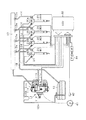
はじめに、図1を参照して、本実施形態に係るコモンレール式燃料噴射システム(車載エンジンシステム)の概略について説明する。なお、本実施形態では多気筒(例えば直列4気筒)の4ストローク、レシプロ式ディーゼルエンジン(内燃機関)を想定している。このエンジンでは、吸排気弁のカム軸に設けられた気筒判別センサ(電磁ピックアップ)にてその時の対象シリンダが逐次判別され、4つのシリンダ#1〜#4について、それぞれ吸入・圧縮・燃焼・排気の4行程による1燃焼サイクルが「720°CA」周期で、詳しくは例えば各シリンダ間で「180°CA」ずらしてシリンダ#1,#3,#4,#2の順に逐次実行される。
First, an outline of a common rail fuel injection system (vehicle engine system) according to the present embodiment will be described with reference to FIG. In this embodiment, a multi-cylinder (for example, in-line four-cylinder) four-stroke, reciprocating diesel engine (internal combustion engine) is assumed. In this engine, a cylinder discrimination sensor (electromagnetic pickup) provided on the camshaft of the intake / exhaust valve sequentially discriminates the target cylinder at that time, and intake, compression, combustion, and exhaust for each of the four
同図1に示されるように、このシステムは、大きくは、電子制御ユニットであるECU(燃料噴射制御手段)30が、各種センサからのセンサ出力(検出結果)を取り込み、それら各センサ出力に基づいて燃料供給系を構成する各装置の駆動を制御するように構成されている。ECU30は、吸入調整弁11cに対する電流供給量を調整して燃料ポンプ11の燃料吐出量を所望の値に制御することで、コモンレール12(蓄圧容器)内の燃料圧力(燃圧センサ20aにて測定される時々の燃料圧力)を目標値(目標燃圧)にフィードバック制御(例えばPID制御)している。そして、その燃料圧力に基づいて、対象エンジンの所定シリンダに対する燃料噴射量、ひいては同エンジンの出力(出力軸の回転速度やトルク)を所望の大きさに制御している。
As shown in FIG. 1, this system is roughly based on an ECU (fuel injection control means) 30 that is an electronic control unit that captures sensor outputs (detection results) from various sensors and based on these sensor outputs. The drive of each device constituting the fuel supply system is controlled. The
燃料供給系を構成する諸々の装置は、燃料上流側から、燃料タンク10、燃料ポンプ11、コモンレール12、及びインジェクタ20(燃料噴射弁)の順に配設されている。このうち、燃料タンク10と燃料ポンプ11とは、燃料フィルタ10bを介して配管10aにより接続されている。
Various devices constituting the fuel supply system are arranged in order of the
燃料ポンプ11は、駆動軸11dによって駆動される高圧ポンプ11a及び低圧ポンプ11bを有し、低圧ポンプ11bによって上記燃料タンク10から汲み上げられた燃料を、高圧ポンプ11aにて加圧して吐出するように構成されている。そして、高圧ポンプ11aに送られる燃料圧送量、ひいては燃料ポンプ11の燃料吐出量は、燃料ポンプ11の燃料吸入側に設けられた吸入調整弁(SCV:Suction Control Valve)11cによって調量される。すなわち、この燃料ポンプ11では、吸入調整弁11c(例えば非通電時に開弁するノーマリオン型の調整弁)の駆動電流量(ひいては弁開度)を調整することで、同ポンプ11からの燃料吐出量を所望の値に制御することができるようになっている。
The
こうした燃料ポンプ11により燃料タンク10から燃料フィルタ10bを介して汲み上げられた燃料は、コモンレール12へ加圧供給(圧送)される。そして、コモンレール12は、その燃料ポンプ11から圧送された燃料を高圧状態で蓄えてこれを、シリンダ毎に設けられた高圧配管14を通じて、各シリンダ#1〜#4のインジェクタ20へそれぞれ分配供給する。これらインジェクタ20(#1)〜(#4)の燃料排出口21は、それぞれ余分な燃料を燃料タンク10へ戻すための配管18とつながっている。また、コモンレール12と高圧配管14との間には、コモンレール12から高圧配管14に流れる燃料の圧力脈動を減衰させるオリフィス12a(燃料脈動軽減手段)が備えられている。
The fuel pumped up by the
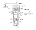
図2に、上記インジェクタ20の詳細構造を示す。なお、上記4つのインジェクタ20(#1)〜(#4)は基本的には同様の構造(例えば図2に示す構造)となっている。いずれのインジェクタ20も、燃焼用のエンジン燃料(燃料タンク10内の燃料)を利用した油圧駆動式の燃料噴射弁であり、燃料噴射に際しての駆動動力の伝達が油圧室Cd(制御室)を介して行われる。同図2に示されるように、このインジェクタ20は、非通電時に閉弁状態となるノーマリクローズ型の燃料噴射弁として構成されている。
FIG. 2 shows a detailed structure of the
インジェクタ20のハウジング20eに形成された燃料流入口22には、コモンレール12から送られてくる高圧燃料が流入し、流入した高圧燃料の一部は油圧室Cdに流入し、他は噴射孔20fに向けて流れる。油圧室Cdには制御弁23により開閉されるリーク孔24が形成されており、制御弁23によりリーク孔24が開放されると、油圧室Cdの燃料はリーク孔24から燃料排出口21を経て燃料タンク10に戻される。
The high pressure fuel sent from the
このインジェクタ20の燃料噴射に際しては、二方電磁弁を構成するソレノイド20bに対する通電状態(通電/非通電)に応じて制御弁23を作動させることで、油圧室Cdの密閉度合、ひいては同油圧室Cdの圧力(ニードル弁20cの背圧に相当)が増減される。そして、その圧力の増減により、スプリング20d(コイルばね)の伸張力に従って又は抗して、ニードル弁20cがハウジング20e内を往復動(上下)することで、噴射孔20f(必要な数だけ穿設)までの燃料供給通路25が、その中途(詳しくは往復動に基づきニードル弁20cが着座又は離座するテーパ状のシート面)で開閉される。
When fuel is injected from the
ここで、ニードル弁20cの駆動制御は、オンオフ制御を通じて行われる。すなわち、ニードル弁20cの駆動部(上記二方電磁弁)には、ECU30からオンオフを指令するパルス信号(通電信号)が送られる。そして、パルスオン(又はオフ)によりニードル弁20cがリフトアップして噴射孔20fが開放され、パルスオフ(又はオン)によりリフトダウンして噴射孔20fが閉塞される。
Here, drive control of the
ちなみに、上記油圧室Cdの増圧処理は、コモンレール12からの燃料供給によって行われる。他方、油圧室Cdの減圧処理は、ソレノイド20bへの通電により制御弁23を作動させてリーク孔24を開放させることによって行われる。これにより、当該インジェクタ20と燃料タンク10とを接続する配管18(図1)を通じてその油圧室Cd内の燃料が上記燃料タンク10へ戻される。つまり、油圧室Cd内の燃料圧力を制御弁23の開閉作動により調整することで、噴射孔20fを開閉するニードル弁20cの作動が制御される。
Incidentally, the pressure increasing process of the hydraulic chamber Cd is performed by supplying fuel from the
このように、上記インジェクタ20は、弁本体(ハウジング20e)内部での所定の往復動作に基づいて噴射孔20fまでの燃料供給通路25を開閉(開放・閉鎖)することにより当該インジェクタ20の開弁及び閉弁を行うニードル弁20cを備える。そして、非駆動状態では、定常的に付与される閉弁側への力(スプリング20dによる伸張力)でニードル弁20cが閉弁側へ変位するとともに、駆動状態では、駆動力が付与されることにより上記スプリング20dの伸張力に抗してニードル弁20cが開弁側へ変位する。そしてこの際、それら非駆動状態と駆動状態とでは、ニードル弁20cのリフト量が略対称に変化する。
In this way, the
インジェクタ20には、燃料圧力を検出する燃圧センサ20a(図1も併せ参照)が取り付けられている。具体的には、ハウジング20eに形成された燃料流入口22と高圧配管14とを治具20jで連結させ、この治具20jに燃圧センサ20aを取り付けている。このようにインジェクタ20の燃料流入口22に燃圧センサ20aを取り付けることで、燃料流入口22における燃料圧力(インレット圧)の随時の検出が可能とされている。具体的には、この燃圧センサ20aの出力により、当該インジェクタ20の噴射動作に伴う燃料圧力の変動パターンや、燃料圧力レベル(安定圧力)、燃料噴射圧力等を検出(測定)することができる。
A
燃圧センサ20aは、複数のインジェクタ20(#1)〜(#4)の各々に対して設けられている。そして、これら燃圧センサ20aの出力に基づいて、所定の噴射について、インジェクタ20の噴射動作に伴う燃料圧力の変動パターンを高い精度で検出することができるようになっている(詳しくは後述)。
The
また、図示しない車両(例えば4輪乗用車又はトラック等)には、上記各センサの他にもさらに、車両制御のための各種のセンサが設けられている。例えば対象エンジンの出力軸であるクランク軸41の外周側には、所定クランク角毎に(例えば30°CA周期で)クランク角信号を出力するクランク角センサ42(例えば電磁ピックアップ)が、同クランク軸41の回転角度位置や回転速度(エンジン回転速度)等を検出するために設けられている。また、アクセルペダルの状態(変位量)に応じた電気信号を出力するアクセルセンサ44が、運転者によるアクセルペダルの操作量(踏み込み量)を検出するために設けられている。
A vehicle (not shown) (for example, a four-wheel passenger car or a truck) is provided with various sensors for vehicle control in addition to the above sensors. For example, on the outer peripheral side of the crankshaft 41 that is the output shaft of the target engine, a crank angle sensor 42 (for example, an electromagnetic pickup) that outputs a crank angle signal at every predetermined crank angle (for example, in a cycle of 30 ° CA) is provided on the crankshaft. 41 is provided for detecting the rotational angle position, rotational speed (engine rotational speed), and the like. Further, an
こうしたシステムの中で、本実施形態の燃料噴射制御手段として機能するとともに、電子制御ユニットとして主体的にエンジン制御を行う部分がECU30である。このECU30(エンジン制御用ECU)は、周知のマイクロコンピュータ(図示略)を備えて構成され、上記各種センサの検出信号に基づいて対象エンジンの運転状態やユーザの要求を把握し、それに応じて上記吸入調整弁11cやインジェクタ20等の各種アクチュエータを操作することにより、その時々の状況に応じた最適な態様で上記エンジンに係る各種の制御を行っている。
In such a system, the
また、このECU30に搭載されるマイクロコンピュータは、各種の演算を行うCPU(基本処理装置)、その演算途中のデータや演算結果等を一時的に記憶するメインメモリとしてのRAM、プログラムメモリとしてのROM、データ保存用メモリとしてのEEPROM、バックアップRAM(ECU30の主電源停止後も車載バッテリ等のバックアップ電源により常時給電されているメモリ)等を備えて構成されている。そして、ROMには、当該燃料噴射制御に係るプログラムを含めたエンジン制御に係る各種のプログラムや制御マップ等が、またデータ保存用メモリ(例えばEEPROM)には、対象エンジンの設計データをはじめとする各種の制御データ等が、それぞれ予め格納されている。
The microcomputer mounted on the
本実施形態では、ECU30が、随時入力される各種のセンサ出力(検出信号)に基づいて、その時に出力軸(クランク軸41)に生成すべきトルク(要求トルク)、ひいてはその要求トルクを満足するための燃料噴射量を算出する。こうして、インジェクタ20の燃料噴射量を可変設定することで、各シリンダ内(燃焼室)での燃料燃焼を通じて生成されるトルク(生成トルク)、ひいては実際に出力軸(クランク軸41)へ出力される軸トルク(出力トルク)を制御する(要求トルクへ一致させる)ようになっている。
In the present embodiment, the
すなわち、このECU30は、例えば時々のエンジン運転状態や運転者によるアクセルペダルの操作量等に応じた燃料噴射量を算出し、所望の噴射時期に同期して、その燃料噴射量での燃料噴射を指示する噴射制御信号(駆動量)を上記インジェクタ20へ出力する。そしてこれにより、すなわち同インジェクタ20の駆動量(例えば開弁時間)に基づいて、対象エンジンの出力トルクが目標値へ制御されることになる。
That is, the
なお周知のように、ディーゼルエンジンにおいては、定常運転時、新気量増大やポンピングロス低減等の目的で、同エンジンの吸気通路に設けられた吸気絞り弁(スロットル弁)が略全開状態に保持される。したがって、定常運転時の燃焼制御(特にトルク調整に係る燃焼制御)としては燃料噴射量のコントロールが主となっている。 As is well known, in a diesel engine, the intake throttle valve (throttle valve) provided in the intake passage of the engine is maintained in a substantially fully open state for the purpose of increasing the amount of fresh air and reducing pumping loss during steady operation. Is done. Therefore, control of the fuel injection amount is mainly used as combustion control during steady operation (particularly combustion control related to torque adjustment).
以下、図3を参照して、本実施形態に係る燃料噴射制御の基本的な処理手順について説明する。なお、この図3の処理において用いられる各種パラメータの値は、例えばECU30に搭載されたRAMやEEPROM、あるいはバックアップRAM等の記憶装置に随時記憶され、必要に応じて随時更新される。そして、これら各図の一連の処理は、基本的には、ECU30でROMに記憶されたプログラムが実行される。
Hereinafter, with reference to FIG. 3, a basic processing procedure of the fuel injection control according to the present embodiment will be described. Note that the values of various parameters used in the processing of FIG. 3 are stored as needed in a storage device such as a RAM, EEPROM, or backup RAM mounted in the
同図3に示すように、この一連の処理においては、まずステップS11で、所定のパラメータ、例えばその時のエンジン回転速度(クランク角センサ42による実測値)及び燃料圧力(燃圧センサ20aによる実測値)、さらには運転者によるその時のアクセル操作量(アクセルセンサ44による実測値)等を読み込む。
As shown in FIG. 3, in this series of processing, first, in step S11, predetermined parameters, for example, the engine speed at that time (actual value measured by the crank angle sensor 42) and fuel pressure (actual value measured by the
続くステップS12では、上記ステップS11で読み込んだ各種パラメータに基づいて噴射パターンを設定する。例えば単段噴射の場合にはその噴射の噴射量Q(噴射時間)が、また多段噴射の噴射パターンの場合にはトルクに寄与する各噴射の総噴射量Q(総噴射時間)が、それぞれ上記出力軸(クランク軸41)に生成すべきトルク(アクセル操作量等から算出される要求トルク、いわばその時のエンジン負荷に相当)に応じて可変設定される。 In subsequent step S12, an injection pattern is set based on the various parameters read in step S11. For example, in the case of single-stage injection, the injection amount Q (injection time) of the injection, and in the case of the injection pattern of multi-stage injection, the total injection amount Q (total injection time) of each injection that contributes to torque is described above. It is variably set according to the torque to be generated on the output shaft (crankshaft 41) (required torque calculated from the accelerator operation amount or the like, which corresponds to the engine load at that time).
この噴射パターンは、例えば上記ROMに記憶保持された所定のマップ(噴射制御用マップ、数式でも可)及び補正係数に基づいて取得される。詳しくは、例えば予め上記所定パラメータ(ステップS11)の想定される範囲について試験により最適噴射パターン(適合値)を求め、その噴射制御用マップに書き込んでおく。 This injection pattern is acquired based on, for example, a predetermined map (an injection control map, which may be a mathematical expression) stored in the ROM and a correction coefficient. More specifically, for example, an optimum injection pattern (adapted value) is obtained in advance for the assumed range of the predetermined parameter (step S11) and written in the injection control map.
この噴射パターンは、例えば噴射段数(1燃焼サイクル中の噴射回数)、並びにそれら各噴射の噴射時期(噴射タイミング)及び噴射時間(噴射量に相当)等のパラメータにより定められるものである。こうして、上記噴射制御用マップは、それらパラメータと最適噴射パターンとの関係を示すものとなっている。 This injection pattern is determined by parameters such as the number of injection stages (the number of injections in one combustion cycle), the injection timing (injection timing) and the injection time (corresponding to the injection amount) of each injection. Thus, the injection control map shows the relationship between these parameters and the optimal injection pattern.
そして、この噴射制御用マップで取得された噴射パターンを、別途更新されている補正係数(例えばECU30内のEEPROMに記憶)に基づいて補正する(例えば「設定値=マップ上の値/補正係数」なる演算を行う)ことで、その時に噴射すべき噴射パターン、ひいてはその噴射パターンに対応した上記インジェクタ20に対する指令信号を得る。補正係数(厳密には複数種の係数のうちの所定の係数)は、別途の処理により内燃機関の運転中に逐次更新されている。
Then, the injection pattern acquired in the injection control map is corrected based on a separately updated correction coefficient (for example, stored in the EEPROM in the ECU 30) (for example, “set value = value on the map / correction coefficient”). To obtain a command signal for the
なお、上記噴射パターンの設定(ステップS12)には、同噴射パターンの要素(上記噴射段数等)毎に別々に設けられた各マップを用いるようにしても、あるいはこれら噴射パターンの各要素を幾つか(例えば全て)まとめて作成したマップを用いるようにしてもよい。 It should be noted that, for the setting of the injection pattern (step S12), each map provided separately for each element (the number of injection stages, etc.) of the injection pattern may be used, or several elements of these injection patterns may be used. Alternatively (for example, all) maps created together may be used.
こうして設定された噴射パターン、ひいてはその噴射パターンに対応する指令値(指令信号)は、続くステップS13で使用される。すなわち、同ステップS13(指令信号出力手段)では、その指令値(指令信号)に基づいて(詳しくは上記インジェクタ20へその指令信号を出力して)、同インジェクタ20の駆動を制御する。そして、このインジェクタ20の駆動制御をもって、図3の一連の処理を終了する。
The injection pattern thus set, and thus the command value (command signal) corresponding to the injection pattern, is used in the subsequent step S13. That is, in step S13 (command signal output means), the drive of the
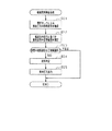
次に、インジェクタ20の噴射孔20f詰まりやニードル弁20cの摺動不良等による噴射異常の発生を検出する噴射異常検出処理について、図4を用いて説明する。図4に示す一連の処理は、所定周期(例えば先述のCPUが行う演算周期)又は所定のクランク角度毎に実行される。なお、この処理を実行するECU30は噴射異常検出装置に相当する。
Next, an injection abnormality detection process for detecting occurrence of an injection abnormality due to clogging of the injection hole 20f of the
まずステップS21で、燃圧センサ20aの出力値(検出圧力)を取り込む。この取り込み処理は複数の燃圧センサ20aの各々について実行され、以降のステップS22〜S25についても、複数のインジェクタ20の各々について噴射異常検出処理が実行される。
First, in step S21, the output value (detected pressure) of the
ここで、ステップS21の取り込み処理について図5を用いて詳細に説明する。図5(a)は、図3のステップS13にてインジェクタ20に出力される噴射指令信号を示しており、この指令信号のパルスオンによりソレノイド20bが作動して噴射孔20fが開弁する。つまり、噴射指令信号のパルスオン時期Isにより噴射開始が指令され、パルスオフ時期Ieにより噴射終了が指令される。よって、指令信号のパルスオン(噴射指令)により噴射孔20fの開弁時間Tqを制御することで、噴射量Qを制御している。図5(b)は、上記噴射指令に伴い生じる噴射孔20fからの燃料噴射率の変化を示し、図5(c)は、噴射率の変化に伴い生じる燃圧センサ20aの出力値(検出圧力)の変化を示す。
Here, the capturing process in step S21 will be described in detail with reference to FIG. FIG. 5A shows the injection command signal output to the
そして、ECU30は、図4の処理とは別のサブルーチン処理により、燃圧センサ20aの出力値を検出しており、そのサブルーチン処理では燃圧センサ20aの出力値を、該センサ出力で圧力推移波形の軌跡(図5(c)にて例示される軌跡)が描かれる程度に短い間隔(図4の所定周期よりも短い間隔)にて逐次取得している。具体的には、50μsecよりも短い間隔(より望ましくは20μsec)でセンサ出力を逐次取得する。
The
なお、図5(c)に示すインレット圧の変動(圧力推移波形)から図5(b)に示す噴射率の変化を推定し、推定した噴射率変化は、図3のステップS11で用いる先述の噴射制御用マップの更新(学習)等に用いられる。ちなみに、燃圧センサ20aの検出圧力の変動と噴射率の変化とは以下に説明する相関があるため、上述の如く噴射率の変化を推定することができる。
Note that the change in the injection rate shown in FIG. 5B is estimated from the fluctuation (pressure transition waveform) of the inlet pressure shown in FIG. 5C, and the estimated change in the injection rate is the above-described change used in step S11 in FIG. This is used for updating (learning) the injection control map. Incidentally, since the fluctuation in the detected pressure of the
先ず、図5(a)に示すように噴射開始指令Isがなされた後、噴射率が応答遅れTaの後R3の時点で上昇を開始して噴射が開始される。一方、検出圧力は、この噴射開始時点R3の前に変化点P1にて下降する。これは、P1の時点で制御弁23がリーク孔24を開放し、油圧室Cdが減圧処理されることに起因する。その後、油圧室Cdが十分に減圧された時点で、変化点P2にてP1からの下降が一旦停止する。次に、R3の時点で噴射率が上昇を開始したことに伴い、検出圧力は変化点P3にて下降を開始する。その後、R4の時点で噴射率が最大噴射率に到達したことに伴い、検出圧力の下降は変化点P4にて停止する。
First, as shown in FIG. 5 (a), after the injection start command Is is made, the injection rate starts to rise at the time point R3 after the response delay Ta, and the injection is started. On the other hand, the detected pressure falls at the change point P1 before the injection start time R3. This is due to the fact that the
次に、検出圧力は変化点P5にて上昇する。これは、P5の時点で制御弁23がリーク孔24を閉塞し、油圧室Cdが増圧処理されることに起因する。その後、油圧室Cdが十分に増圧された時点で、変化点P6にてP5からの上昇が一旦停止する。次に、R7の時点で噴射率が下降を開始したことに伴い、検出圧力は変化点P7にて上昇を開始する。その後、R8の時点で噴射率がゼロになり実際の噴射が終了したことに伴い、検出圧力の上昇は変化点P8にて停止する。P8以降の検出圧力は、図示を省略しているが、一定の周期で下降と上昇を繰り返しながら減衰した後安定する。
Next, the detected pressure rises at the change point P5. This is due to the fact that the
以上により、燃圧センサ20aによる検出圧力の変動のうち変化点P3及びP8を検出することで、噴射率の上昇開始時点R3(噴射開始時点)及び下降終了時点R8(噴射終了時点)を推定することができる。また、以下に説明する検出圧力の変動と噴射率の変化との相関関係に基づき、検出圧力の変動から噴射率の変化を推定できる。
As described above, by detecting the change points P3 and P8 among the fluctuations in the pressure detected by the
つまり、検出圧力の変化点P3からP4までの圧力下降率Pαと、噴射率の変化点R3からR4までの噴射率上昇率Rαとは相関がある。変化点P7からP8までの圧力上昇率Pγと変化点R7からR8までの噴射率下降率Rγとは相関がある。変化点P3からP4までの圧力下降量Pβと変化点R3からR4までの噴射率上昇量Rβとは相関がある。よって、燃圧センサ20aによる検出圧力の変動から圧力下降率Pα、圧力上量率Pγ及び圧力下降量Pβを検出することで、噴射率の噴射率上昇率Rα、噴射率下降率Rγ及び噴射率上昇量Rβを推定することができる。以上の如く噴射率の各種状態R3,R8,Rα,Rβ,Rγを推定することができ、よって、図6(b)に示す燃料噴射率の変化を推定することができる。
That is, there is a correlation between the pressure decrease rate Pα from the detected pressure change points P3 to P4 and the injection rate increase rate Rα from the injection rate change points R3 to R4. There is a correlation between the pressure increase rate Pγ from the change points P7 to P8 and the injection rate decrease rate Rγ from the change points R7 to R8. There is a correlation between the pressure decrease amount Pβ from the change points P3 to P4 and the injection rate increase amount Rβ from the change points R3 to R4. Therefore, the injection rate increase rate Rα, the injection rate decrease rate Rγ, and the injection rate increase are detected by detecting the pressure decrease rate Pα, the pressure increase rate rate Pγ, and the pressure decrease rate Pβ from the fluctuation of the detected pressure by the
さらに、実噴射開始から終了までの噴射率の積分値(斜線を付した符号Sに示す部分の面積)は噴射量に相当する。そして、検出圧力の推移波形のうち実噴射開始から終了までの噴射率変化に対応する部分(変化点P3〜P8の部分)の圧力の積分値と噴射率の積分値Sとは相関がある。よって、燃圧センサ20aによる検出圧力の変動から圧力積分値を算出することで、噴射量Qに相当する噴射率積分値Sを推定することができる。
Further, the integral value of the injection rate from the start to the end of actual injection (the area of the portion indicated by the hatched symbol S) corresponds to the injection amount. The integral value of the pressure and the integral value S of the injection rate in the portion corresponding to the change in the injection rate from the start to the end of the actual injection (the portion of the change points P3 to P8) in the transition waveform of the detected pressure have a correlation. Therefore, the injection rate integrated value S corresponding to the injection amount Q can be estimated by calculating the pressure integrated value from the fluctuation of the detected pressure by the
図5の説明に戻り、先述のステップS21に続くステップS22では、噴射指令信号による噴射開始指令時期Is及び噴射終了指令時期Ieに基づき、正常な状態で噴射がなされていれば検出圧力がどのような態様で変動するかを推定し、推定した変動態様(推移波形)に対する正常範囲を想定する(詳細は後述)。続くステップS23(噴射異常判定手段)では、ステップS21にて取得した検出圧力に基づく実際の推移波形が、ステップS22にて想定した正常範囲内で挙動する波形であるか否かを判定する。 Returning to the description of FIG. 5, in step S <b> 22 following step S <b> 21 described above, what is the detected pressure if injection is performed in a normal state based on the injection start command timing Is and the injection end command timing Ie based on the injection command signal. The normal range for the estimated variation mode (transition waveform) is assumed (details will be described later). In subsequent step S23 (injection abnormality determining means), it is determined whether or not the actual transition waveform based on the detected pressure acquired in step S21 is a waveform that behaves within the normal range assumed in step S22.
正常範囲内でないと判定された場合には、ステップS24(噴射異常判定手段)において、噴射異常が発生していると判断する異常判定処理を実行し、続くステップS25にて異常信号を出力し、先述のEEPROM等に異常発生の旨を記憶する。なお、異常信号には、後に詳述する異常内容の情報が含まれている。当該異常信号を受信した異常発生時処理装置(例えばECU30のマイコン)は、インジェクタ20の交換を促す報知を行ったり、該当するインジェクタ20への噴射指令信号の出力を禁止して噴射を確実に停止させる等の処理を実行する。
When it is determined that it is not within the normal range, in step S24 (injection abnormality determination means), an abnormality determination process for determining that an injection abnormality has occurred is performed, and in step S25, an abnormality signal is output. The fact that an abnormality has occurred is stored in the aforementioned EEPROM or the like. Note that the abnormality signal includes information on abnormality contents to be described in detail later. Upon receipt of the abnormality signal, the abnormality occurrence processing device (for example, the microcomputer of the ECU 30) notifies the user to replace the
次に、ステップS22にて想定される推移波形の挙動の正常範囲について説明する。本実施形態に係る正常範囲とは、以下の(a)〜(f)の条件を全て満たす範囲のことであり、少なくとも1つの条件を満たしていなければ、ステップS23にて噴射異常が発生していると判定される。 Next, the normal range of the behavior of the transition waveform assumed in step S22 will be described. The normal range according to the present embodiment is a range that satisfies all the following conditions (a) to (f). If at least one condition is not satisfied, an injection abnormality occurs in step S23. It is determined that
(a)図6中の一点鎖線に示すように、正常噴射であれば、噴射開始指令時期Isから第1所定時間T11内に噴射が開始され、噴射率は変化点R3にて上昇を開始する。そして、このようにR3の時点で噴射率が上昇を開始したことに伴い、検出圧力は変化点P3にて下降を開始する。したがって、噴射指令信号による噴射開始指令時期Isから第1所定時間T11内に圧力下降開始の変化点P3が現れることを、正常範囲の推移波形とする。 (A) As shown by the alternate long and short dash line in FIG. 6, if the injection is normal, the injection is started within the first predetermined time T11 from the injection start command timing Is, and the injection rate starts increasing at the change point R3. . As the injection rate starts increasing at the time point R3 as described above, the detected pressure starts decreasing at the change point P3. Accordingly, the transition waveform of the normal range is that the change point P3 of the pressure drop start appears within the first predetermined time T11 from the injection start command timing Is based on the injection command signal.
なお、上記第1所定時間T11は、変化点P1が現れる以前の検出圧力に応じて可変設定することが望ましい。例えば、噴射開始指令時点Isでの検出圧力が高いほど、正常噴射における変化点P1は早期に現れることとなるので、第1所定時間T11を短く設定することが望ましい。 The first predetermined time T11 is preferably variably set according to the detected pressure before the change point P1 appears. For example, the higher the detected pressure at the injection start command time Is, the earlier the change point P1 in normal injection appears, so it is desirable to set the first predetermined time T11 shorter.
そして、図6中の実線に示すように、噴射開始指令時期Isから第1所定時間T11が経過しても、噴射率変化点R3に伴う検出圧力変化点P3が現れなければ、ステップS23にて噴射異常が発生していると判定される。そして、噴射開始指令に反して無噴射となっている異常状態の可能性があるとの異常内容情報を、ステップS25にて出力される異常信号に含ませる。 Then, as shown by the solid line in FIG. 6, if the detected pressure change point P3 associated with the injection rate change point R3 does not appear even after the first predetermined time T11 has elapsed from the injection start command timing Is, in step S23. It is determined that an injection abnormality has occurred. Then, abnormality content information indicating that there is a possibility of an abnormal state in which there is no injection against the injection start command is included in the abnormality signal output in step S25.
(b)図7中の一点鎖線に示すように、正常噴射であれば、噴射終了指令時期Ieから第2所定時間T12内に噴射が終了し、変化点R7から下降を続ける噴射率は変化点R8にて下降を終了する。そして、このようにR8の時点で噴射率が下降を終了したことに伴い、検出圧力は変化点P8にて上昇を終了する。したがって、噴射指令信号による噴射終了指令時期Ieから第2所定時間T12内に圧力上昇終了の変化点P8が現れることを、正常範囲の推移波形とする。 (B) As indicated by the alternate long and short dash line in FIG. 7, if the injection is normal, the injection is completed within the second predetermined time T12 from the injection end command timing Ie, and the injection rate that continues to decrease from the change point R7 is the change point. The descent ends at R8. As the injection rate ends decreasing at the time point R8 as described above, the detected pressure ends increasing at the change point P8. Therefore, the transition waveform of the normal range is that the change point P8 of the pressure increase end appears within the second predetermined time T12 from the injection end command timing Ie based on the injection command signal.
なお、上記第2所定時間T12は、変化点P1が現れる以前の検出圧力及び噴射指令信号による開弁指令時間Tqの少なくとも一方に応じて、可変設定することが望ましい。例えば、噴射開始指令時点Isでの検出圧力が高いほど、或いは開弁指令時間Tqが長いほど、正常噴射における変化点P8は早期に現れることとなるので、第2所定時間T12を短く設定することが望ましい。 The second predetermined time T12 is preferably variably set according to at least one of the detected pressure before the change point P1 appears and the valve opening command time Tq based on the injection command signal. For example, the higher the detected pressure at the injection start command time Is or the longer the valve opening command time Tq, the earlier the change point P8 in normal injection will appear, so the second predetermined time T12 should be set shorter. Is desirable.
そして、図7中の実線に示すように、噴射終了指令時期Ieから第2所定時間T12が経過しても、噴射率変化点R8に伴う検出圧力変化点P8が現れなければ、ステップS23にて噴射異常が発生していると判定される。そして、噴射終了指令に反して噴射が継続されているとの異常内容情報を、ステップS25にて出力される異常信号に含ませる。 Then, as shown by the solid line in FIG. 7, if the detected pressure change point P8 accompanying the injection rate change point R8 does not appear even after the second predetermined time T12 has elapsed from the injection end command timing Ie, in step S23. It is determined that an injection abnormality has occurred. Then, abnormality content information indicating that the injection is continued against the injection end command is included in the abnormality signal output in step S25.
(c)図8中の一点鎖線に示すように、正常噴射であれば、噴射終了指令時期Ieから第3所定時間T13内に噴射率は変化点R7にて下降を開始し、当該下降開始に伴い検出圧力は変化点P7にて上昇を開始する。したがって、噴射指令信号による噴射終了指令時期Ieから第3所定時間T13内に圧力上昇開始の変化点P7が現れることを、正常範囲の推移波形とする。 (C) As shown by the alternate long and short dash line in FIG. 8, if the injection is normal, the injection rate starts to decrease at the change point R7 within the third predetermined time T13 from the injection end command timing Ie. Accordingly, the detected pressure starts to rise at the change point P7. Accordingly, the transition waveform of the normal range is that the change point P7 of the pressure increase start appears within the third predetermined time T13 from the injection end command timing Ie based on the injection command signal.
なお、上記第3所定時間T13は、変化点P1が現れる以前の検出圧力及び噴射指令信号による開弁指令時間Tqの少なくとも一方に応じて、可変設定することが望ましい。例えば、噴射開始指令時点Isでの検出圧力が高いほど、或いは開弁指令時間Tqが長いほど、正常噴射における変化点P7は早期に現れることとなるので、第3所定時間T13を短く設定することが望ましい。 The third predetermined time T13 is desirably variably set according to at least one of the detected pressure before the change point P1 appears and the valve opening command time Tq based on the injection command signal. For example, the higher the detected pressure at the injection start command time Is or the longer the valve opening command time Tq, the earlier the change point P7 in normal injection will appear, so the third predetermined time T13 should be set shorter. Is desirable.
そして、図8中の実線に示すように、噴射終了指令時期Ieから第3所定時間T13が経過しても、噴射率変化点R7に伴う検出圧力変化点P7が現れなければ、ステップS23にて噴射異常が発生していると判定される。そして、噴射終了指令に反して噴射率下降が開始されていないとの異常内容情報を、ステップS25にて出力される異常信号に含ませる。 Then, as shown by the solid line in FIG. 8, if the detected pressure change point P7 associated with the injection rate change point R7 does not appear even after the third predetermined time T13 has elapsed from the injection end command timing Ie, in step S23. It is determined that an injection abnormality has occurred. Then, abnormality content information indicating that the injection rate lowering is not started contrary to the injection end command is included in the abnormality signal output in step S25.
(d)図9中の一点鎖線に示すように、正常噴射であれば、噴射率変化点R4が現れた以後の最大噴射率Rβは所定の閾値Rβ1を超えることとなる。したがって、圧力変化点P4が現れてから第4所定時間T14が経過するまでに、変化点P3からP4までの圧力下降量Pβが閾値Rβ1に相当する閾値を超えて下降することを、正常範囲の推移波形とする。 (D) As indicated by the alternate long and short dash line in FIG. 9, in the case of normal injection, the maximum injection rate Rβ after the injection rate change point R4 appears exceeds a predetermined threshold value Rβ1. Therefore, the pressure decrease amount Pβ from the change point P3 to P4 falls below the threshold value corresponding to the threshold value Rβ1 before the fourth predetermined time T14 elapses after the pressure change point P4 appears. A transition waveform.
なお、上記第4所定時間T14及び閾値Rβ1は、変化点P1が現れる以前の検出圧力及び噴射指令信号による開弁指令時間Tqの少なくとも一方に応じて、可変設定することが望ましい。例えば、噴射開始指令時点Isでの検出圧力が高いほど、或いは開弁指令時間Tqが長いほど、正常噴射における最大噴射率Rβは早期かつ大きく現れることとなるので、第4所定時間T14を短く設定し、閾値Rβ1を大きく設定することが望ましい。 The fourth predetermined time T14 and the threshold value Rβ1 are preferably variably set according to at least one of the detected pressure before the change point P1 appears and the valve opening command time Tq based on the injection command signal. For example, as the detected pressure at the injection start command time Is is higher or the valve opening command time Tq is longer, the maximum injection rate Rβ in normal injection appears earlier and larger, so the fourth predetermined time T14 is set shorter. It is desirable to set the threshold value Rβ1 large.
そして、図9中の実線に示すように、最大噴射率到達時点R4から第4所定時間T14が経過しても、圧力下降量Pβが閾値を超えて下降しなければ、ステップS23にて噴射異常が発生していると判定される。そして、指令した最大噴射率まで噴射率が十分に高くなっていないとの異常内容情報を、ステップS25にて出力される異常信号に含ませる。 As shown by the solid line in FIG. 9, if the pressure decrease amount Pβ does not decrease beyond the threshold value even after the fourth predetermined time T14 has elapsed from the maximum injection rate arrival point R4, the injection abnormality is detected in step S23. Is determined to have occurred. Then, abnormality content information indicating that the injection rate is not sufficiently high up to the commanded maximum injection rate is included in the abnormality signal output in step S25.
(e)図10中の一点鎖線に示すように、正常噴射であれば、噴射率の上昇率Rαは所定の上昇率Rα1より大きい値となる。したがって、圧力下降率Pαが所定上昇率Rα1に相当する所定圧力下降率Pαより小さい値となり急激に圧力下降していることを、正常範囲の推移波形とする。 (E) As indicated by the alternate long and short dash line in FIG. 10, in the case of normal injection, the increase rate Rα of the injection rate is greater than the predetermined increase rate Rα1. Therefore, the transition waveform of the normal range is that the pressure decrease rate Pα is smaller than the predetermined pressure decrease rate Pα corresponding to the predetermined increase rate Rα1, and the pressure is rapidly decreased.
なお、上記所定圧力下降率Pα1は、変化点P1が現れる以前の検出圧力及び噴射指令信号による開弁指令時間Tqの少なくとも一方に応じて、可変設定することが望ましい。例えば、噴射開始指令時点Isでの検出圧力が高いほど、或いは開弁指令時間Tqが長いほど、正常噴射における噴射率の上昇率Rαは大きい値となり急激に上昇することとなるので、所定上昇率Rα1を大きく設定することが望ましい。 The predetermined pressure drop rate Pα1 is preferably set variably according to at least one of the detected pressure before the change point P1 appears and the valve opening command time Tq based on the injection command signal. For example, as the detected pressure at the injection start command time Is is higher or the valve opening command time Tq is longer, the rate of increase Rα of the injection rate in normal injection becomes larger and increases rapidly. It is desirable to set Rα1 large.
そして、図10中の実線に示すように、噴射率の上昇率Rαが所定上昇率Rαより小さければ、ステップS23にて噴射異常が発生していると判定される。そして、実際の噴射率の上昇率が指令した上昇率よりも低くなっているとの異常内容情報を、ステップS25にて出力される異常信号に含ませる。 Then, as shown by the solid line in FIG. 10, if the increase rate Rα of the injection rate is smaller than the predetermined increase rate Rα, it is determined in step S23 that an injection abnormality has occurred. Then, abnormality content information indicating that the actual increase rate of the injection rate is lower than the commanded increase rate is included in the abnormality signal output in step S25.
(f)図10及び図11中の一点鎖線に示すように、正常噴射であれば、噴射量Qに相当する噴射率の積分値Sは所定の下限値より大きく、上限値よりも小さい値となる。したがって、噴射率積分値Sが下限値及び上限値の範囲内となるような圧力変動となる波形を、正常範囲の推移波形とする。 (F) As shown by the one-dot chain line in FIG. 10 and FIG. 11, if normal injection, the integral value S of the injection rate corresponding to the injection amount Q is larger than a predetermined lower limit value and smaller than the upper limit value. Become. Therefore, a waveform that causes a pressure fluctuation that causes the injection rate integral value S to be within the range between the lower limit value and the upper limit value is set as a transition waveform in the normal range.
なお、上記上限値及び下限値は、変化点P1が現れる以前の検出圧力及び噴射指令信号による開弁指令時間Tqの少なくとも一方に応じて、可変設定することが望ましい。例えば、噴射開始指令時点Isでの検出圧力が高いほど、或いは開弁指令時間Tqが長いほど、噴射量Qは多くなるので、上限値及び下限値を高い値に設定することが望ましい。 The upper limit value and the lower limit value are desirably variably set according to at least one of the detected pressure before the change point P1 appears and the valve opening command time Tq based on the injection command signal. For example, the higher the detected pressure at the injection start command time Is or the longer the valve opening command time Tq, the greater the injection amount Q. Therefore, it is desirable to set the upper limit value and the lower limit value to high values.
そして、図10及び図11中の実線に示すように、噴射率積分値Sが下限値よりも小さい、或いは上限値よりも大きければ、ステップS23にて噴射異常が発生していると判定される。そして、実際の噴射量が指令した噴射量に対して過少或いは過多となっているとの異常内容情報を、ステップS25にて出力される異常信号に含ませる。 Then, as shown by the solid lines in FIGS. 10 and 11, if the injection rate integral value S is smaller than the lower limit value or larger than the upper limit value, it is determined in step S23 that an injection abnormality has occurred. . Then, abnormality content information indicating that the actual injection amount is too small or excessive with respect to the commanded injection amount is included in the abnormality signal output in step S25.
条件(a)に基づき異常判定を行うにあたり、圧力下降開始の変化点P3(噴射開始時期)を検出する処理を実行している時のECU30は噴射開始検出手段に相当する。条件(b)に基づき異常判定を行うにあたり、圧力上昇終了の変化点P8(噴射終了時期)を検出する処理を実行している時のECU30は噴射終了検出手段に相当する。条件(c)に基づき異常判定を行うにあたり、圧力上昇開始の変化点P7(ニードル弁20cの閉弁作動開始時期)を検出する処理を実行している時のECU30は噴射終了作動開始検出手段に相当する。条件(d)に基づき異常判定を行うにあたり、圧力下降量Pβを検出する処理を実行している時のECU30は最大噴射率到達検出手段に相当する。条件(e)に基づき異常判定を行うにあたり、圧力下降率Pαを検出する処理を実行している時のECU30は噴射率上昇検出手段に相当する。条件(f)に基づき異常判定を行うにあたり、噴射量Qを算出する処理を実行している時のECU30は噴射量算出手段に相当する。
When performing abnormality determination based on the condition (a), the
以上により本実施形態では、燃圧センサ20aをインジェクタ20に取り付けているため、コモンレール12に取り付けた場合に比べて噴射孔20fに近い位置に燃圧センサ20aは配置されることとなる。よって、噴射孔20fでの圧力変動(推移波形)を詳細に精度良く検出することができる(S21)。一方、噴射指令信号による噴射開始指令時期Is、噴射終了指令時期Ie、及びこれらの時期Is,Ieにて特定される噴射時間Tqから、正常な噴射がなされていた場合に想定される検出圧力の変動態様(推移波形)を算出する(S22)。そして、検出した推移波形と想定される推移波形とを比較する(S23)ことで燃料噴射の異常を検出する(S24)。
As described above, in this embodiment, since the
したがって、実際の噴射状態が燃圧センサ20aにより直接的に検出され、その検出結果に基づき噴射異常の発生を検出するので、フィードバック制御に用いる目標値に間接的に現れる異常に基づき噴射異常を検出する従来装置に比べ、噴射異常を即時かつ精度良く検出できる。
Therefore, the actual injection state is directly detected by the
しかも、本実施形態によれば、先述の条件(a)〜(f)を満たすか否かに基づき噴射異常を検出するので、異常内容を情報として異常信号に含ませることができる。よって、インジェクタ20の交換を促す報知を行ったり、該当するインジェクタ20への噴射指令信号の出力を禁止して噴射を確実に停止させる等の異常発生時の異常対応処理を、その異常内容に応じた処理内容にすることができる。
In addition, according to the present embodiment, since the injection abnormality is detected based on whether or not the above-described conditions (a) to (f) are satisfied, the abnormality content can be included in the abnormality signal as information. Therefore, an abnormality handling process at the time of occurrence of an abnormality such as notification for urging replacement of the
(その他の実施形態)
本発明は上記実施形態の記載内容に限定されず、上記各実施形態の特徴的構造をそれぞれ任意に組み合わせるようにしてもよい。また、例えば次のように実施しても良い。
(Other embodiments)
The present invention is not limited to the description of the above embodiment, and the characteristic structures of the above embodiments may be arbitrarily combined. For example, you may implement as follows.
・図9に示す上記条件(d)に関し、上記実施形態では第4所定時間T14の計時開始を圧力変化点P4(R4)の時点としているが、例えば、圧力変化点P3(R3)の時点から第4所定時間T14の計時を開始してもよい。但しこの場合には、噴射率上昇率Rαが十分大きくないとの異常状態である場合にも、条件(d)を満たしていないとの異常判定がなされるので、噴射率上昇率Rαの異常及び最大噴射率Rβの異常のいずれが異常の原因になっているかを特定することができない。これに対し、上記実施形態では圧力変化点P3(R3)の時点から第4所定時間T14の計時を開始しているので、条件(d)を満たしていないとの異常判定がなされた場合、最大噴射率Rβの異常である旨を特定できる。 With respect to the condition (d) shown in FIG. 9, in the above embodiment, the timing of the fourth predetermined time T14 is set as the time of the pressure change point P4 (R4). For example, from the time of the pressure change point P3 (R3) You may start time measurement of 4th predetermined time T14. However, in this case, even in an abnormal state where the injection rate increase rate Rα is not sufficiently large, an abnormality determination that the condition (d) is not satisfied is made, and therefore an abnormality in the injection rate increase rate Rα and It cannot be identified which of the abnormalities in the maximum injection rate Rβ is causing the abnormality. On the other hand, in the above embodiment, since the measurement of the fourth predetermined time T14 is started from the time of the pressure change point P3 (R3), when the abnormality determination that the condition (d) is not satisfied is made, the maximum It can be specified that the injection rate Rβ is abnormal.
・上記実施形態では、条件(a)〜(f)の全てを満たす場合に正常噴射であると判定されるが、これら複数の条件(a)〜(f)のうち任意に選択された複数又は1つの条件を満たす場合に正常噴射であると判定するようにしてもよい。 In the above embodiment, it is determined that the normal injection is performed when all of the conditions (a) to (f) are satisfied, but a plurality of arbitrarily selected from the plurality of conditions (a) to (f) or You may make it determine with it being normal injection, when one condition is satisfy | filled.
・図4のステップS23の処理を実行するにあたり、燃圧センサ20aの検出圧力から推定された噴射率について正常範囲の変動態様になっているかを判定して噴射異常を検出してもよいし、噴射率についてではなく燃圧センサ20aの検出圧力について、正常範囲の変動態様になっているかを判定して噴射異常を検出するようにしてもよい。
In performing the process of step S23 of FIG. 4, it may be determined whether the injection rate estimated from the detected pressure of the
・図2に例示した電磁駆動式のインジェクタ20に替えて、ピエゾ駆動式のインジェクタを用いるようにしてもよい。また、リーク孔24等からの圧力リークを伴わない燃料噴射弁、例えば駆動動力の伝達に油圧室Cdを介さない直動式のインジェクタ(例えば近年開発されつつある直動式ピエゾインジェクタ)等を用いることもできる。そして、直動式のインジェクタを用いた場合には、噴射率の制御が容易となる。
A piezo drive injector may be used instead of the
・燃圧センサ20aをインジェクタ20に取り付けるにあたり、上記実施形態では、インジェクタ20の燃料流入口22に燃圧センサ20aを取り付けているが、図2中の一点鎖線200aに示すようにハウジング20eの内部に燃圧センサ200aを組み付けて、燃料流入口22から噴射孔20fに至るまでの内部燃料通路25の燃料圧力を検出するように構成してもよい。
-In attaching the
そして、上述の如く燃料流入口22に取り付ける場合には、ハウジング20eの内部に取り付ける場合に比べて燃圧センサ20aの取付構造を簡素にできる。一方、ハウジング20eの内部に取り付ける場合には、燃料流入口22に取り付ける場合に比べて燃圧センサ20aの取り付け位置が噴射孔20fに近い位置となるので、噴射孔20fでの圧力変動をより的確に検出することができる。
And when attaching to the
・高圧配管14に燃圧センサ20aを取り付けるようにしてもよい。この場合、コモンレール12から一定距離だけ離間した位置に燃圧センサ20aを取り付けることが望ましい。
The
・コモンレール12と高圧配管14との間に、コモンレール12から高圧配管14に流れる燃料の流量を制限する流量制限手段を備えてもよい。この流量制限手段は、高圧配管14やインジェクタ20等の損傷による燃料漏れにより過剰な燃料流出が発生した時に、流路を閉塞するよう機能するものであり、例えば過剰流量時に流路を閉塞するように作動するボール等の弁体により構成することが具体例として挙げられる。なお、オリフィス12a(燃料脈動軽減手段)と流量制限手段とを一体に構成したフローダンパを採用してもよい。
-Between the
・また、燃圧センサ20aをオリフィス及び流量制限手段の燃料流れ下流側に配置する構成の他に、オリフィス及び流量制限手段の少なくとも一方に対して下流側に配置するよう構成してもよい。
Further, in addition to the configuration in which the
・燃圧センサ20aの数は任意であり、例えば1つのシリンダの燃料流通経路に対して2つ以上のセンサを設けるようにしてもよい。また、上記実施形態で説明した燃圧センサ20aに加えて、さらにコモンレール12内の圧力を測定するレール圧センサを備える構成としてもよい。
The number of
・制御対象とするエンジンの種類やシステム構成も、用途等に応じて適宜に変更可能である。例えば、上記実施形態ではディーゼルエンジンに本発明を適用した場合について言及したが、例えば火花点火式のガソリンエンジン(特に直噴エンジン)等についても、基本的には同様に本発明を適用することができる。直噴式ガソリンエンジンの燃料噴射システムでは、燃料(ガソリン)を高圧状態で蓄えるデリバリパイプを備えており、このデリバリパイプに対して燃料ポンプから燃料が圧送されるとともに、同デリバリパイプ内の高圧燃料が複数のインジェクタ20に分配され、エンジン燃焼室内に噴射供給される。なお、かかるシステムでは、デリバリパイプが蓄圧容器に相当する。また、本発明に係る装置及びシステムは、シリンダ内に燃料を直接的に噴射する燃料噴射弁に限らず、エンジンの吸気通路又は排気通路に燃料を噴射する燃料噴射弁についても適用できる。
-The type and system configuration of the engine to be controlled can be changed as appropriate according to the application. For example, in the above embodiment, the case where the present invention is applied to a diesel engine has been described. However, for example, the present invention can be basically applied to a spark ignition type gasoline engine (particularly a direct injection engine). it can. The fuel injection system of a direct injection type gasoline engine is equipped with a delivery pipe that stores fuel (gasoline) in a high-pressure state. The fuel is pumped from the fuel pump to the delivery pipe, and the high-pressure fuel in the delivery pipe is The fuel is distributed to a plurality of
12…コモンレール(蓄圧容器)、20…インジェクタ(燃料噴射弁)、20a,200a…燃圧センサ、20f…噴射孔、30…ECU(噴射異常検出装置)、S13…指令信号出力手段、S23,S24…噴射異常判定手段、S23…噴射開始検出手段、噴射終了検出手段、噴射終了作動開始検出手段、最大噴射率到達検出手段、噴射率上昇検出手段、噴射量算出手段。
DESCRIPTION OF
Claims (25)
前記蓄圧容器から前記燃料噴射弁の噴射孔に至るまでの燃料通路のうち前記蓄圧容器に対して前記噴射孔に近い側に配置され、前記噴射孔からの燃料噴射に伴い変動する燃料の圧力を検出する燃圧センサと、
燃料の噴射態様を指令する噴射指令信号を前記燃料噴射弁に出力する指令信号出力手段と、
前記燃圧センサの検出圧力が前記噴射指令信号から想定される範囲の変動態様で変動しているか否かを判定し、前記想定される範囲の変動態様でないと判定した場合に噴射異常が発生していると判断する噴射異常判定手段と、
前記検出圧力の推移波形中に現れる、実噴射開始に起因した圧力下降の開始を検出する噴射開始検出手段と、
を備え、
前記噴射異常判定手段は、前記噴射指令信号による噴射開始指令時期から第1所定時間内に前記圧力下降の開始が検出されなかった場合に、前記想定される範囲の変動態様でないと判定することを特徴とする噴射異常検出装置。 An injection abnormality detection device applied to a fuel injection system that injects fuel accumulated in a pressure accumulator from a fuel injection valve,
The fuel passage from the pressure accumulating container to the injection hole of the fuel injection valve is disposed on the side closer to the injection hole with respect to the pressure accumulating container, and the fuel pressure that fluctuates with the fuel injection from the injection hole. A fuel pressure sensor to detect,
Command signal output means for outputting an injection command signal for commanding the fuel injection mode to the fuel injection valve;
It is determined whether or not the detected pressure of the fuel pressure sensor fluctuates in a variation mode within a range assumed from the injection command signal, and an injection abnormality occurs when it is determined that the fuel pressure sensor does not have a variation mode in the assumed range. Injection abnormality determining means for determining that there is,
Injection start detection means for detecting the start of pressure drop caused by the actual injection start, which appears in the transition waveform of the detected pressure;
Equipped with a,
The injection abnormality determination means determines that the variation in the assumed range is not detected when the start of the pressure drop is not detected within a first predetermined time from the injection start command timing by the injection command signal. An abnormal jet detection device.
前記噴射異常判定手段は、前記噴射指令信号による噴射終了指令時期から第2所定時間内に前記圧力上昇の終了が検出されなかった場合に、前記想定される範囲の変動態様でないと判定することを特徴とする請求項1又は2に記載の噴射異常検出装置。 An injection end detecting means for detecting the end of the pressure rise caused by the end of the actual injection, which appears in the transition waveform of the detected pressure,
The injection abnormality determination means determines that the variation in the assumed range is not detected when the end of the pressure increase is not detected within a second predetermined time from the injection end command timing based on the injection command signal. The ejection abnormality detection device according to claim 1 or 2, characterized in that
前記蓄圧容器から前記燃料噴射弁の噴射孔に至るまでの燃料通路のうち前記蓄圧容器に対して前記噴射孔に近い側に配置され、前記噴射孔からの燃料噴射に伴い変動する燃料の圧力を検出する燃圧センサと、
燃料の噴射態様を指令する噴射指令信号を前記燃料噴射弁に出力する指令信号出力手段と、
前記燃圧センサの検出圧力が前記噴射指令信号から想定される範囲の変動態様で変動しているか否かを判定し、前記想定される範囲の変動態様でないと判定した場合に噴射異常が発生していると判断する噴射異常判定手段と、
前記検出圧力の推移波形中に現れる、実噴射終了に起因した圧力上昇の終了を検出する噴射終了検出手段と、
を備え、
前記噴射異常判定手段は、前記噴射指令信号による噴射終了指令時期から第2所定時間内に前記圧力上昇の終了が検出されなかった場合に、前記想定される範囲の変動態様でないと判定することを特徴とする噴射異常検出装置。 An injection abnormality detection device applied to a fuel injection system that injects fuel accumulated in a pressure accumulator from a fuel injection valve,
The fuel passage from the pressure accumulating container to the injection hole of the fuel injection valve is disposed on the side closer to the injection hole with respect to the pressure accumulating container, and the fuel pressure that fluctuates with the fuel injection from the injection hole. A fuel pressure sensor to detect,
Command signal output means for outputting an injection command signal for commanding the fuel injection mode to the fuel injection valve;
It is determined whether or not the detected pressure of the fuel pressure sensor fluctuates in a variation mode within a range assumed from the injection command signal, and an injection abnormality occurs when it is determined that the fuel pressure sensor does not have a variation mode in the assumed range. Injection abnormality determining means for determining that there is,
An injection end detection means for detecting the end of the pressure rise caused by the end of the actual injection, which appears in the transition waveform of the detected pressure;
With
The injection abnormality determination means determines that the variation in the assumed range is not detected when the end of the pressure increase is not detected within a second predetermined time from the injection end command timing based on the injection command signal. jetting abnormality detection device shall be the features.
前記噴射異常判定手段は、前記噴射指令信号による噴射終了指令時期から第3所定時間内に前記圧力上昇の開始が検出されなかった場合に、前記想定される範囲の変動態様でないと判定することを特徴とする請求項1〜5のいずれか1つに記載の噴射異常検出装置。 An injection end operation start detecting means for detecting the start of pressure increase caused by the actual injection rate decrease start by starting the injection end operation appearing in the transition waveform of the detected pressure;
The injection abnormality determination means determines that the variation in the assumed range is not detected when the start of the pressure increase is not detected within a third predetermined time from the injection end command timing based on the injection command signal. The injection abnormality detection device according to any one of claims 1 to 5.
前記蓄圧容器から前記燃料噴射弁の噴射孔に至るまでの燃料通路のうち前記蓄圧容器に対して前記噴射孔に近い側に配置され、前記噴射孔からの燃料噴射に伴い変動する燃料の圧力を検出する燃圧センサと、
燃料の噴射態様を指令する噴射指令信号を前記燃料噴射弁に出力する指令信号出力手段と、
前記燃圧センサの検出圧力が前記噴射指令信号から想定される範囲の変動態様で変動しているか否かを判定し、前記想定される範囲の変動態様でないと判定した場合に噴射異常が発生していると判断する噴射異常判定手段と、
前記検出圧力の推移波形中に現れる、噴射終了作動を開始することによる実噴射率下降開始に起因した圧力上昇の開始を検出する噴射終了作動開始検出手段と、
を備え、
前記噴射異常判定手段は、前記噴射指令信号による噴射終了指令時期から第3所定時間内に前記圧力上昇の開始が検出されなかった場合に、前記想定される範囲の変動態様でないと判定することを特徴とする噴射異常検出装置。 An injection abnormality detection device applied to a fuel injection system that injects fuel accumulated in a pressure accumulator from a fuel injection valve,
The fuel passage from the pressure accumulating container to the injection hole of the fuel injection valve is disposed on the side closer to the injection hole with respect to the pressure accumulating container, and the fuel pressure that fluctuates with the fuel injection from the injection hole. A fuel pressure sensor to detect,
Command signal output means for outputting an injection command signal for commanding the fuel injection mode to the fuel injection valve;
It is determined whether or not the detected pressure of the fuel pressure sensor fluctuates in a variation mode within a range assumed from the injection command signal, and an injection abnormality occurs when it is determined that the fuel pressure sensor does not have a variation mode in the assumed range. Injection abnormality determining means for determining that there is,
An injection end operation start detecting means for detecting the start of pressure increase caused by the start of actual injection rate decrease by starting the injection end operation, which appears in the transition waveform of the detected pressure;
With
The injection abnormality determination means determines that the variation in the assumed range is not detected when the start of the pressure increase is not detected within a third predetermined time from the injection end command timing based on the injection command signal. jetting abnormality detection device shall be the features.
前記噴射異常判定手段は、前記最大噴射率到達後の第4所定時間内に前記検出圧力が所定の閾値を超えなかった場合に、前記想定される範囲の変動態様でないと判定することを特徴とする請求項1〜8のいずれか1つに記載の噴射異常検出装置。 Maximum injection rate arrival detection means for detecting the end of the pressure drop due to the arrival of the maximum injection rate after the start of actual injection, which appears in the transition waveform of the detected pressure,
The injection abnormality determining means determines that the variation is not in the assumed range when the detected pressure does not exceed a predetermined threshold within a fourth predetermined time after reaching the maximum injection rate. The injection abnormality detection device according to any one of claims 1 to 8 .
前記蓄圧容器から前記燃料噴射弁の噴射孔に至るまでの燃料通路のうち前記蓄圧容器に対して前記噴射孔に近い側に配置され、前記噴射孔からの燃料噴射に伴い変動する燃料の圧力を検出する燃圧センサと、
燃料の噴射態様を指令する噴射指令信号を前記燃料噴射弁に出力する指令信号出力手段と、
前記燃圧センサの検出圧力が前記噴射指令信号から想定される範囲の変動態様で変動しているか否かを判定し、前記想定される範囲の変動態様でないと判定した場合に噴射異常が発生していると判断する噴射異常判定手段と、
前記検出圧力の推移波形中に現れる、実噴射開始後の最大噴射率到達に起因した圧力下降の終了を検出する最大噴射率到達検出手段と、
を備え、
前記噴射異常判定手段は、前記最大噴射率到達後の第4所定時間内に前記検出圧力が所定の閾値を超えなかった場合に、前記想定される範囲の変動態様でないと判定することを特徴とする噴射異常検出装置。 An injection abnormality detection device applied to a fuel injection system that injects fuel accumulated in a pressure accumulator from a fuel injection valve,
The fuel passage from the pressure accumulating container to the injection hole of the fuel injection valve is disposed on the side closer to the injection hole with respect to the pressure accumulating container, and the fuel pressure that fluctuates with the fuel injection from the injection hole. A fuel pressure sensor to detect,
Command signal output means for outputting an injection command signal for commanding the fuel injection mode to the fuel injection valve;
It is determined whether or not the detected pressure of the fuel pressure sensor fluctuates in a variation mode within a range assumed from the injection command signal, and an injection abnormality occurs when it is determined that the fuel pressure sensor does not have a variation mode in the assumed range. Injection abnormality determining means for determining that there is,
Maximum injection rate arrival detection means for detecting the end of the pressure drop caused by reaching the maximum injection rate after the start of actual injection, which appears in the transition waveform of the detected pressure,
With
The injection abnormality determining means determines that the variation is not in the assumed range when the detected pressure does not exceed a predetermined threshold within a fourth predetermined time after reaching the maximum injection rate. injection you Cum abnormality detection device.
前記噴射異常判定手段は、前記下降率が所定の下降率より小さい場合に、前記想定される範囲の変動態様でないと判定することを特徴とする請求項1〜11のいずれか1つに記載の噴射異常検出装置。 An injection rate increase detecting means for detecting a decrease rate of pressure decrease caused by an increase in injection rate after the start of actual injection, which appears in the transition waveform of the detected pressure;
The said injection abnormality determination means determines that it is not the fluctuation | variation aspect of the said range when the said fall rate is smaller than a predetermined fall rate, The Claim 1 characterized by the above-mentioned. Injection abnormality detection device.
前記蓄圧容器から前記燃料噴射弁の噴射孔に至るまでの燃料通路のうち前記蓄圧容器に対して前記噴射孔に近い側に配置され、前記噴射孔からの燃料噴射に伴い変動する燃料の圧力を検出する燃圧センサと、
燃料の噴射態様を指令する噴射指令信号を前記燃料噴射弁に出力する指令信号出力手段と、
前記燃圧センサの検出圧力が前記噴射指令信号から想定される範囲の変動態様で変動しているか否かを判定し、前記想定される範囲の変動態様でないと判定した場合に噴射異常が発生していると判断する噴射異常判定手段と、
前記検出圧力の推移波形中に現れる、実噴射開始後の噴射率上昇に起因した圧力下降の下降率を検出する噴射率上昇検出手段と、
を備え、
前記噴射異常判定手段は、前記下降率が所定の下降率より小さい場合に、前記想定される範囲の変動態様でないと判定することを特徴とする噴射異常検出装置。 An injection abnormality detection device applied to a fuel injection system that injects fuel accumulated in a pressure accumulator from a fuel injection valve,
The fuel passage from the pressure accumulating container to the injection hole of the fuel injection valve is disposed on the side closer to the injection hole with respect to the pressure accumulating container, and the fuel pressure that fluctuates with the fuel injection from the injection hole. A fuel pressure sensor to detect,
Command signal output means for outputting an injection command signal for commanding the fuel injection mode to the fuel injection valve;
It is determined whether or not the detected pressure of the fuel pressure sensor fluctuates in a variation mode within a range assumed from the injection command signal, and an injection abnormality occurs when it is determined that the fuel pressure sensor does not have a variation mode in the assumed range. Injection abnormality determining means for determining that there is,
An injection rate increase detection means for detecting a rate of decrease in pressure decrease caused by an increase in injection rate after the start of actual injection, which appears in the transition waveform of the detected pressure;
With
The defective injection determination means, wherein when lowering rate is smaller than the predetermined decrease rate, jetting abnormality detecting device you wherein the determining is not a fluctuation mode in a range where the envisioned.
前記噴射異常判定手段は、前記噴射量算出手段により算出された噴射量が所定の下限値より少ない場合に、前記想定される範囲の変動態様でないと判定することを特徴とする請求項1〜14のいずれか1つに記載の噴射異常検出装置。 An injection amount calculating means for calculating an integral value of a pressure corresponding to an injection amount for a waveform corresponding to an injection rate change from the start to the end of actual injection in the transition waveform of the detected pressure;
The defective injection determination unit, when the injection amount calculated by the injection amount calculating means is smaller than a predetermined lower limit value, claim, wherein the determining is not a fluctuation mode in a range where the envisaged 1-14 The injection abnormality detection apparatus as described in any one of these .
前記蓄圧容器から前記燃料噴射弁の噴射孔に至るまでの燃料通路のうち前記蓄圧容器に対して前記噴射孔に近い側に配置され、前記噴射孔からの燃料噴射に伴い変動する燃料の圧力を検出する燃圧センサと、
燃料の噴射態様を指令する噴射指令信号を前記燃料噴射弁に出力する指令信号出力手段と、
前記燃圧センサの検出圧力が前記噴射指令信号から想定される範囲の変動態様で変動しているか否かを判定し、前記想定される範囲の変動態様でないと判定した場合に噴射異常が発生していると判断する噴射異常判定手段と、
前記検出圧力の推移波形のうち実噴射開始から終了までの噴射率変化に対応する部分の波形について、噴射量に相当する圧力の積分値を算出する噴射量算出手段と、
を備え、
前記噴射異常判定手段は、前記噴射量算出手段により算出された噴射量が所定の下限値より少ない場合に、前記想定される範囲の変動態様でないと判定することを特徴とする噴射異常検出装置。 An injection abnormality detection device applied to a fuel injection system that injects fuel accumulated in a pressure accumulator from a fuel injection valve,
The fuel passage from the pressure accumulating container to the injection hole of the fuel injection valve is disposed on the side closer to the injection hole with respect to the pressure accumulating container, and the fuel pressure that fluctuates with the fuel injection from the injection hole. A fuel pressure sensor to detect,
Command signal output means for outputting an injection command signal for commanding the fuel injection mode to the fuel injection valve;
It is determined whether or not the detected pressure of the fuel pressure sensor fluctuates in a variation mode within a range assumed from the injection command signal, and an injection abnormality occurs when it is determined that the fuel pressure sensor does not have a variation mode in the assumed range. Injection abnormality determining means for determining that there is,
An injection amount calculating means for calculating an integral value of a pressure corresponding to an injection amount for a waveform corresponding to an injection rate change from the start to the end of actual injection in the transition waveform of the detected pressure;
With
The defective injection determination means, wherein, when the injection amount calculated by the injection amount calculating means is smaller than a predetermined lower limit value, it features a to that jetting abnormality detecting determines that not a fluctuation mode in a range where the envisaged apparatus.
前記燃圧センサは前記オリフィスの燃料流れ下流側に配置されていることを特徴とする請求項1〜17のいずれか1つに記載の噴射異常検出装置。 The fuel passage from the pressure accumulating vessel to the fuel inlet of the fuel injection valve is provided with an orifice that attenuates the pressure pulsation of the fuel in the common rail,
The injection abnormality detecting device according to any one of claims 1 to 17, wherein the fuel pressure sensor is arranged on the downstream side of the fuel flow of the orifice .
前記蓄圧容器から前記燃料噴射弁の噴射孔に至るまでの燃料通路のうち前記蓄圧容器に対して前記噴射孔に近い側に配置され、前記噴射孔からの燃料噴射に伴い変動する燃料の圧力を検出する燃圧センサと、
燃料の噴射態様を指令する噴射指令信号を前記燃料噴射弁に出力する指令信号出力手段と、
前記燃圧センサの検出圧力が前記噴射指令信号から想定される範囲の変動態様で変動しているか否かを判定し、前記想定される範囲の変動態様でないと判定した場合に噴射異常が発生していると判断する噴射異常判定手段と、
を備え、
前記蓄圧容器から前記燃料噴射弁の燃料流入口までの燃料通路には、コモンレール内の燃料の圧力脈動を減衰させるオリフィスが備えられており、
前記燃圧センサは前記オリフィスの燃料流れ下流側に配置されていることを特徴とする噴射異常検出装置。 An injection abnormality detection device applied to a fuel injection system that injects fuel accumulated in a pressure accumulator from a fuel injection valve,
The fuel passage from the pressure accumulating container to the injection hole of the fuel injection valve is disposed on the side closer to the injection hole with respect to the pressure accumulating container, and the fuel pressure that fluctuates with the fuel injection from the injection hole. A fuel pressure sensor to detect,
Command signal output means for outputting an injection command signal for commanding the fuel injection mode to the fuel injection valve;
It is determined whether or not the detected pressure of the fuel pressure sensor fluctuates in a variation mode within a range assumed from the injection command signal, and an injection abnormality occurs when it is determined that the fuel pressure sensor does not have a variation mode in the assumed range. Injection abnormality determining means for determining that there is,
With
The fuel passage from the pressure accumulating vessel to the fuel inlet of the fuel injection valve is provided with an orifice that attenuates the pressure pulsation of the fuel in the common rail,
The fuel pressure sensor morphism injection you characterized in that it is arranged in the fuel flow downstream of the orifice abnormality detection device.
前記噴射異常判定手段は、前記噴射量算出手段により算出された噴射量が所定の上限値より多い場合に、前記想定される範囲の変動態様でないと判定することを特徴とする請求項1〜19のいずれか1つに記載の噴射異常検出装置。 An injection amount calculating means for calculating an integral value of a pressure corresponding to an injection amount for a waveform corresponding to an injection rate change from the start to the end of actual injection in the transition waveform of the detected pressure;
The defective injection determination means according to claim 1 to 19 injection amount calculated by the injection amount calculating means, characterized in that determining and if greater than a predetermined upper limit value, not an adjustable manner in the range of the envisaged The injection abnormality detection apparatus as described in any one of these .
燃料を蓄圧する蓄圧容器、及び前記蓄圧容器で蓄圧された燃料を噴射する燃料噴射弁の少なくとも一方と、At least one of a pressure accumulation container for accumulating fuel, and a fuel injection valve for injecting fuel accumulated in the pressure accumulation container;
を備えることを特徴とする燃料噴射システム。A fuel injection system comprising:
Priority Applications (4)
| Application Number | Priority Date | Filing Date | Title |
|---|---|---|---|
| JP2007258512A JP4420097B2 (en) | 2007-10-02 | 2007-10-02 | Injection abnormality detection device and fuel injection system |
| EP08163936.1A EP2045458B1 (en) | 2007-10-02 | 2008-09-09 | Defective injection detection device and fuel injection system having the same |
| US12/236,882 US7933712B2 (en) | 2007-10-02 | 2008-09-24 | Defective injection detection device and fuel injection system having the same |
| CN2008101617592A CN101403346B (en) | 2007-10-02 | 2008-09-26 | Defective injection detection device and fuel injection system having the same |
Applications Claiming Priority (1)
| Application Number | Priority Date | Filing Date | Title |
|---|---|---|---|
| JP2007258512A JP4420097B2 (en) | 2007-10-02 | 2007-10-02 | Injection abnormality detection device and fuel injection system |
Publications (2)
| Publication Number | Publication Date |
|---|---|
| JP2009085164A JP2009085164A (en) | 2009-04-23 |
| JP4420097B2 true JP4420097B2 (en) | 2010-02-24 |
Family
ID=40028931
Family Applications (1)
| Application Number | Title | Priority Date | Filing Date |
|---|---|---|---|
| JP2007258512A Active JP4420097B2 (en) | 2007-10-02 | 2007-10-02 | Injection abnormality detection device and fuel injection system |
Country Status (4)
| Country | Link |
|---|---|
| US (1) | US7933712B2 (en) |
| EP (1) | EP2045458B1 (en) |
| JP (1) | JP4420097B2 (en) |
| CN (1) | CN101403346B (en) |
Families Citing this family (26)
| Publication number | Priority date | Publication date | Assignee | Title |
|---|---|---|---|---|
| JP4840288B2 (en) * | 2006-11-14 | 2011-12-21 | 株式会社デンソー | Fuel injection apparatus and adjustment method thereof |
| JP4623066B2 (en) | 2007-08-31 | 2011-02-02 | 株式会社デンソー | Injection control device for internal combustion engine |
| US8215288B2 (en) * | 2009-04-29 | 2012-07-10 | GM Global Technology Operations LLC | Control system and method for controlling an engine in response to detecting an out of range pressure signal |
| GB2475060A (en) * | 2009-11-03 | 2011-05-11 | Gm Global Tech Operations Inc | Estimating fuel injecting pressure in an i.c. engine |
| JP4952773B2 (en) | 2009-11-04 | 2012-06-13 | トヨタ自動車株式会社 | Abnormality diagnosis device for fuel pressure sensor |
| JP5206660B2 (en) * | 2009-12-18 | 2013-06-12 | トヨタ自動車株式会社 | Abnormality judgment device for fuel supply system |
| JP4968319B2 (en) | 2009-12-24 | 2012-07-04 | トヨタ自動車株式会社 | Abnormality judgment device for fuel injection valve |
| JP5343877B2 (en) * | 2010-01-28 | 2013-11-13 | トヨタ自動車株式会社 | Injection abnormality detection device |
| DE102010029064A1 (en) * | 2010-05-18 | 2011-11-24 | Robert Bosch Gmbh | Method for monitoring fuel injection valve of injection device of internal combustion engine, involves carrying out opening and closing events by periodic pressurization when periodic change of pressure is detected in line |
| JP5240283B2 (en) * | 2010-12-09 | 2013-07-17 | 株式会社デンソー | Noise diagnosis device for fuel injection system |
| JP5348154B2 (en) * | 2011-02-16 | 2013-11-20 | 株式会社デンソー | Failure injection device for fuel injection system |
| JP5278472B2 (en) * | 2011-03-14 | 2013-09-04 | 株式会社デンソー | Abnormality diagnosis device for fuel injection valve |
| FI20115418A0 (en) * | 2011-05-03 | 2011-05-03 | Waertsilae Finland Oy | FUEL INJECTION UNIT AND SYSTEM |
| DE102011080990B3 (en) * | 2011-08-16 | 2013-01-24 | Mtu Friedrichshafen Gmbh | Common rail system, internal combustion engine and device and method for controlling and / or regulating an internal combustion engine |
| JP5718829B2 (en) * | 2012-01-13 | 2015-05-13 | トヨタ自動車株式会社 | Abnormality judgment device for fuel supply system |
| JP5724953B2 (en) * | 2012-06-14 | 2015-05-27 | 株式会社デンソー | Abnormality judgment device for fuel injection valve |
| JP5704152B2 (en) * | 2012-11-28 | 2015-04-22 | トヨタ自動車株式会社 | Fuel injection device |
| DE102013216255B3 (en) * | 2013-08-15 | 2014-11-27 | Mtu Friedrichshafen Gmbh | Method for injector-specific diagnosis of a fuel injection device and internal combustion engine with a fuel injection device |
| US11649155B2 (en) | 2014-08-14 | 2023-05-16 | Vmi Manufacturing, Llc | Test port for fuel dispenser |
| US9878895B2 (en) * | 2014-08-14 | 2018-01-30 | Gregory E. Young | Test port for fuel dispenser |
| EP3121425A1 (en) * | 2015-07-24 | 2017-01-25 | Winterthur Gas & Diesel AG | Method and device for inspecting an electronically controlled injection device for injecting a fuel into a cylinder of an internal combustion engine |
| DE102016219954B3 (en) | 2016-10-13 | 2018-01-25 | Continental Automotive Gmbh | Method for checking a pressure sensor of a high-pressure injection system, control device, high-pressure injection system and motor vehicle |
| DE102016219959B4 (en) | 2016-10-13 | 2018-06-21 | Continental Automotive Gmbh | Method for checking a calibration of a pressure sensor of a motor vehicle injection system and control device, high-pressure injection system and motor vehicle |
| DE102018002161A1 (en) * | 2018-03-16 | 2019-09-19 | Woodward L'orange Gmbh | arrangement |
| CN111765026B (en) * | 2020-06-24 | 2022-03-29 | 河南柴油机重工有限责任公司 | Test device and test method for detecting oil injection rule of high-pressure common rail system |
| DE112022003885T5 (en) * | 2021-10-04 | 2024-05-16 | Cummins Inc. | Fuel injector calibration and control |
Family Cites Families (32)
| Publication number | Priority date | Publication date | Assignee | Title |
|---|---|---|---|---|
| US3919885A (en) * | 1972-03-24 | 1975-11-18 | Harbeke Gerold J | Apparatus for dynamically analyzing an electronic fuel injection system and the associated engine parts |
| JP3147460B2 (en) | 1991-04-26 | 2001-03-19 | 株式会社デンソー | Fuel injection device for internal combustion engine |
| EP0911508B1 (en) * | 1992-08-20 | 2002-01-16 | Toyota Jidosha Kabushiki Kaisha | Fuel injection controller for use in an internal combustion engine |
| JP2861718B2 (en) | 1993-03-19 | 1999-02-24 | トヨタ自動車株式会社 | Degradation diagnostic device for fuel injection device |
| JPH1089090A (en) * | 1996-09-19 | 1998-04-07 | Isuzu Motors Ltd | Hydraulic actuation type electronic controlled fuel injection device, oil viscosity measuring device, and oil viscosity measuring method |
| DE19729101A1 (en) * | 1997-07-08 | 1999-01-14 | Bosch Gmbh Robert | System for operating an internal combustion engine, in particular a motor vehicle |
| JPH1182134A (en) * | 1997-09-03 | 1999-03-26 | Fuji Heavy Ind Ltd | High pressure fuel system diagnostic device and control device for cylinder fuel injection engine |
| DE19740608C2 (en) * | 1997-09-16 | 2003-02-13 | Daimler Chrysler Ag | Method for determining a fuel injection-related parameter for an internal combustion engine with high-pressure accumulator injection system |
| DE19747231A1 (en) * | 1997-10-25 | 1999-04-29 | Bosch Gmbh Robert | Method for injecting fuel into the combustion chambers of an air-compressing, self-igniting internal combustion engine |
| DE10259797A1 (en) * | 2002-12-19 | 2004-07-15 | Siemens Ag | Device and method for detecting faults in a fuel injection system |
| JP4345547B2 (en) * | 2004-03-31 | 2009-10-14 | トヨタ自動車株式会社 | Hybrid vehicle control system |
| JP4196895B2 (en) * | 2004-07-12 | 2008-12-17 | 株式会社デンソー | Fuel injection device |
| JP4506662B2 (en) * | 2005-12-05 | 2010-07-21 | 株式会社デンソー | Fuel injection control device |
| JP4840288B2 (en) | 2006-11-14 | 2011-12-21 | 株式会社デンソー | Fuel injection apparatus and adjustment method thereof |
| CN101033724B (en) * | 2007-03-12 | 2010-06-23 | 南京林业大学 | Failure diagnosis method of electrically controlled petrol engine fuel injector |
| JP4483908B2 (en) | 2007-08-23 | 2010-06-16 | 株式会社デンソー | Fuel injection control device |
| JP4462307B2 (en) | 2007-08-31 | 2010-05-12 | 株式会社デンソー | Fuel injection device and fuel injection system |
| US8459234B2 (en) | 2007-08-31 | 2013-06-11 | Denso Corporation | Fuel injection device, fuel injection system, and method for determining malfunction of the same |
| JP4424395B2 (en) | 2007-08-31 | 2010-03-03 | 株式会社デンソー | Fuel injection control device for internal combustion engine |
| JP4428427B2 (en) | 2007-08-31 | 2010-03-10 | 株式会社デンソー | Fuel injection characteristic detecting device and fuel injection command correcting device |
| JP4501975B2 (en) | 2007-08-31 | 2010-07-14 | 株式会社デンソー | FUEL INJECTION DEVICE AND METHOD FOR MANUFACTURING FUEL INJECTION DEVICE |
| EP2031224B1 (en) | 2007-08-31 | 2018-11-07 | Denso Corporation | Fuel injection device, fuel injection system, and method for determining malfunction of the same |
| JP4407731B2 (en) | 2007-08-31 | 2010-02-03 | 株式会社デンソー | Fuel injection control device |
| JP4623066B2 (en) | 2007-08-31 | 2011-02-02 | 株式会社デンソー | Injection control device for internal combustion engine |
| JP4462315B2 (en) | 2007-09-24 | 2010-05-12 | 株式会社デンソー | Internal combustion engine control device |
| US7873460B2 (en) | 2007-09-25 | 2011-01-18 | Denso Corporation | Controller for fuel injection system |
| JP4416026B2 (en) | 2007-09-28 | 2010-02-17 | 株式会社デンソー | Control device for accumulator fuel injection system |
| JP4492664B2 (en) | 2007-09-28 | 2010-06-30 | 株式会社デンソー | Fuel supply amount estimation device and fuel pressure injection system |
| JP4782759B2 (en) | 2007-10-24 | 2011-09-28 | 株式会社デンソー | Internal combustion engine control device and internal combustion engine control system |
| JP4577348B2 (en) | 2007-10-24 | 2010-11-10 | 株式会社デンソー | Internal combustion engine control device and internal combustion engine control system |
| JP4525729B2 (en) | 2007-10-26 | 2010-08-18 | 株式会社デンソー | EGR distribution variation detection device |
| JP4462327B2 (en) | 2007-10-26 | 2010-05-12 | 株式会社デンソー | Cylinder characteristic variation detector |
-
2007
- 2007-10-02 JP JP2007258512A patent/JP4420097B2/en active Active
-
2008
- 2008-09-09 EP EP08163936.1A patent/EP2045458B1/en not_active Expired - Fee Related
- 2008-09-24 US US12/236,882 patent/US7933712B2/en active Active
- 2008-09-26 CN CN2008101617592A patent/CN101403346B/en not_active Expired - Fee Related
Also Published As
| Publication number | Publication date |
|---|---|
| US20090088951A1 (en) | 2009-04-02 |
| CN101403346A (en) | 2009-04-08 |
| CN101403346B (en) | 2012-06-20 |
| EP2045458A2 (en) | 2009-04-08 |
| US7933712B2 (en) | 2011-04-26 |
| EP2045458A3 (en) | 2017-04-26 |
| JP2009085164A (en) | 2009-04-23 |
| EP2045458B1 (en) | 2019-06-26 |
Similar Documents
| Publication | Publication Date | Title |
|---|---|---|
| JP4420097B2 (en) | Injection abnormality detection device and fuel injection system | |
| JP4462307B2 (en) | Fuel injection device and fuel injection system | |
| JP5152237B2 (en) | Abnormality judgment method of fuel injection device | |
| JP4462315B2 (en) | Internal combustion engine control device | |
| JP4678397B2 (en) | Fuel injection state detection device | |
| JP4453773B2 (en) | Fuel injection device, fuel injection system, and fuel injection device abnormality determination method | |
| JP4424395B2 (en) | Fuel injection control device for internal combustion engine | |
| JP4501975B2 (en) | FUEL INJECTION DEVICE AND METHOD FOR MANUFACTURING FUEL INJECTION DEVICE | |
| JP4428427B2 (en) | Fuel injection characteristic detecting device and fuel injection command correcting device | |
| JP4407731B2 (en) | Fuel injection control device | |
| JP4492664B2 (en) | Fuel supply amount estimation device and fuel pressure injection system | |
| JP4483908B2 (en) | Fuel injection control device | |
| JP4835716B2 (en) | Fuel injection state detection device | |
| JP4353270B2 (en) | Fuel injection characteristic detection device and engine control system | |
| JP5141723B2 (en) | Fuel injection control device for internal combustion engine | |
| JP5813531B2 (en) | Fuel spray detection device | |
| JP5774521B2 (en) | Fuel leak detection device | |
| JP4893851B2 (en) | Fuel injection state detection device | |
| JP4513895B2 (en) | Fuel injection system control device | |
| JP4269913B2 (en) | Accumulated fuel injection system | |
| JP4689695B2 (en) | Fuel injection system |
Legal Events
| Date | Code | Title | Description |
|---|---|---|---|
| A621 | Written request for application examination |
Free format text: JAPANESE INTERMEDIATE CODE: A621 Effective date: 20090217 |
|
| A131 | Notification of reasons for refusal |
Free format text: JAPANESE INTERMEDIATE CODE: A131 Effective date: 20090825 |
|
| A977 | Report on retrieval |
Free format text: JAPANESE INTERMEDIATE CODE: A971007 Effective date: 20090827 |
|
| A521 | Request for written amendment filed |
Free format text: JAPANESE INTERMEDIATE CODE: A523 Effective date: 20091016 |
|
| TRDD | Decision of grant or rejection written | ||
| A01 | Written decision to grant a patent or to grant a registration (utility model) |
Free format text: JAPANESE INTERMEDIATE CODE: A01 Effective date: 20091110 |
|
| A01 | Written decision to grant a patent or to grant a registration (utility model) |
Free format text: JAPANESE INTERMEDIATE CODE: A01 |
|
| A61 | First payment of annual fees (during grant procedure) |
Free format text: JAPANESE INTERMEDIATE CODE: A61 Effective date: 20091123 |
|
| FPAY | Renewal fee payment (event date is renewal date of database) |
Free format text: PAYMENT UNTIL: 20121211 Year of fee payment: 3 |
|
| R151 | Written notification of patent or utility model registration |
Ref document number: 4420097 Country of ref document: JP Free format text: JAPANESE INTERMEDIATE CODE: R151 |
|
| FPAY | Renewal fee payment (event date is renewal date of database) |
Free format text: PAYMENT UNTIL: 20121211 Year of fee payment: 3 |
|
| FPAY | Renewal fee payment (event date is renewal date of database) |
Free format text: PAYMENT UNTIL: 20131211 Year of fee payment: 4 |
|
| R250 | Receipt of annual fees |
Free format text: JAPANESE INTERMEDIATE CODE: R250 |
|
| R250 | Receipt of annual fees |
Free format text: JAPANESE INTERMEDIATE CODE: R250 |
|
| R250 | Receipt of annual fees |
Free format text: JAPANESE INTERMEDIATE CODE: R250 |
|
| R250 | Receipt of annual fees |
Free format text: JAPANESE INTERMEDIATE CODE: R250 |
|
| R250 | Receipt of annual fees |
Free format text: JAPANESE INTERMEDIATE CODE: R250 |
|
| R250 | Receipt of annual fees |
Free format text: JAPANESE INTERMEDIATE CODE: R250 |
|
| R250 | Receipt of annual fees |
Free format text: JAPANESE INTERMEDIATE CODE: R250 |
|
| R250 | Receipt of annual fees |
Free format text: JAPANESE INTERMEDIATE CODE: R250 |
|
| R250 | Receipt of annual fees |
Free format text: JAPANESE INTERMEDIATE CODE: R250 |