JP4419285B2 - Optical disc recording apparatus and optical disc recording method - Google Patents
Optical disc recording apparatus and optical disc recording method Download PDFInfo
- Publication number
- JP4419285B2 JP4419285B2 JP2000183780A JP2000183780A JP4419285B2 JP 4419285 B2 JP4419285 B2 JP 4419285B2 JP 2000183780 A JP2000183780 A JP 2000183780A JP 2000183780 A JP2000183780 A JP 2000183780A JP 4419285 B2 JP4419285 B2 JP 4419285B2
- Authority
- JP
- Japan
- Prior art keywords
- recording
- recording pulse
- pulse
- pit
- optical disc
- Prior art date
- Legal status (The legal status is an assumption and is not a legal conclusion. Google has not performed a legal analysis and makes no representation as to the accuracy of the status listed.)
- Expired - Fee Related
Links
Images


Classifications
-
- G—PHYSICS
- G11—INFORMATION STORAGE
- G11B—INFORMATION STORAGE BASED ON RELATIVE MOVEMENT BETWEEN RECORD CARRIER AND TRANSDUCER
- G11B7/00—Recording or reproducing by optical means, e.g. recording using a thermal beam of optical radiation by modifying optical properties or the physical structure, reproducing using an optical beam at lower power by sensing optical properties; Record carriers therefor
- G11B7/004—Recording, reproducing or erasing methods; Read, write or erase circuits therefor
- G11B7/0045—Recording
- G11B7/00451—Recording involving ablation of the recording layer
-
- G—PHYSICS
- G11—INFORMATION STORAGE
- G11B—INFORMATION STORAGE BASED ON RELATIVE MOVEMENT BETWEEN RECORD CARRIER AND TRANSDUCER
- G11B19/00—Driving, starting, stopping record carriers not specifically of filamentary or web form, or of supports therefor; Control thereof; Control of operating function ; Driving both disc and head
- G11B19/20—Driving; Starting; Stopping; Control thereof
- G11B19/28—Speed controlling, regulating, or indicating
-
- G—PHYSICS
- G11—INFORMATION STORAGE
- G11B—INFORMATION STORAGE BASED ON RELATIVE MOVEMENT BETWEEN RECORD CARRIER AND TRANSDUCER
- G11B20/00—Signal processing not specific to the method of recording or reproducing; Circuits therefor
- G11B20/10—Digital recording or reproducing
- G11B20/14—Digital recording or reproducing using self-clocking codes
- G11B20/1496—Digital recording or reproducing using self-clocking codes characterised by the use of more than three levels
-
- G—PHYSICS
- G11—INFORMATION STORAGE
- G11B—INFORMATION STORAGE BASED ON RELATIVE MOVEMENT BETWEEN RECORD CARRIER AND TRANSDUCER
- G11B7/00—Recording or reproducing by optical means, e.g. recording using a thermal beam of optical radiation by modifying optical properties or the physical structure, reproducing using an optical beam at lower power by sensing optical properties; Record carriers therefor
- G11B7/004—Recording, reproducing or erasing methods; Read, write or erase circuits therefor
- G11B7/0045—Recording
- G11B7/00456—Recording strategies, e.g. pulse sequences
-
- G—PHYSICS
- G11—INFORMATION STORAGE
- G11B—INFORMATION STORAGE BASED ON RELATIVE MOVEMENT BETWEEN RECORD CARRIER AND TRANSDUCER
- G11B7/00—Recording or reproducing by optical means, e.g. recording using a thermal beam of optical radiation by modifying optical properties or the physical structure, reproducing using an optical beam at lower power by sensing optical properties; Record carriers therefor
- G11B7/12—Heads, e.g. forming of the optical beam spot or modulation of the optical beam
- G11B7/125—Optical beam sources therefor, e.g. laser control circuitry specially adapted for optical storage devices; Modulators, e.g. means for controlling the size or intensity of optical spots or optical traces
- G11B7/126—Circuits, methods or arrangements for laser control or stabilisation
-
- G—PHYSICS
- G11—INFORMATION STORAGE
- G11B—INFORMATION STORAGE BASED ON RELATIVE MOVEMENT BETWEEN RECORD CARRIER AND TRANSDUCER
- G11B7/00—Recording or reproducing by optical means, e.g. recording using a thermal beam of optical radiation by modifying optical properties or the physical structure, reproducing using an optical beam at lower power by sensing optical properties; Record carriers therefor
- G11B7/12—Heads, e.g. forming of the optical beam spot or modulation of the optical beam
- G11B7/125—Optical beam sources therefor, e.g. laser control circuitry specially adapted for optical storage devices; Modulators, e.g. means for controlling the size or intensity of optical spots or optical traces
- G11B7/127—Lasers; Multiple laser arrays
-
- G—PHYSICS
- G11—INFORMATION STORAGE
- G11B—INFORMATION STORAGE BASED ON RELATIVE MOVEMENT BETWEEN RECORD CARRIER AND TRANSDUCER
- G11B2220/00—Record carriers by type
- G11B2220/20—Disc-shaped record carriers
- G11B2220/21—Disc-shaped record carriers characterised in that the disc is of read-only, rewritable, or recordable type
- G11B2220/215—Recordable discs
- G11B2220/218—Write-once discs
-
- G—PHYSICS
- G11—INFORMATION STORAGE
- G11B—INFORMATION STORAGE BASED ON RELATIVE MOVEMENT BETWEEN RECORD CARRIER AND TRANSDUCER
- G11B2220/00—Record carriers by type
- G11B2220/20—Disc-shaped record carriers
- G11B2220/25—Disc-shaped record carriers characterised in that the disc is based on a specific recording technology
- G11B2220/2537—Optical discs
Landscapes
- Physics & Mathematics (AREA)
- Optics & Photonics (AREA)
- Engineering & Computer Science (AREA)
- Signal Processing (AREA)
- Optical Recording Or Reproduction (AREA)
- Optical Head (AREA)
Description
【0001】
【発明の属する技術分野】
本発明は、レーザ光を光ディスクの記録面に照射してピットを形成して情報の記録を行うマーク長記録方式の光ディスク記録装置に関し、特に8倍速記録や12倍速記録など4倍速よりも速い速度で記録を行う光ディスク記録装置及び光ディスク記録方法に関する。
【0002】
【従来の技術】
従来より、光ディスクなどの記録媒体に対して光変調方式記録を行う場合、ディスク上に形成されるピット(マーク)の良好な形成のために、レーザをパルス発光させることにより熱的な制御を行うようにしている。具体的には、レーザを駆動するドライブパルスとしてパルス波形を設定するとともに、各パルス期間のレベル(波高値)も制御して、レーザパワーやレーザ照射期間をコントロールしている。
【0003】
例えば、CD−R(CD-Recordable) やCD−RW(CD-ReWritable) に代表される光記録再生装置では、記録しようとする記録マーク長(又はスペース長)に応じて、その照射するレーザのパルス長又はパルス数を可変することでレーザパワー出力区間を制御するようにしたパルス長記録方式又はパルストレイン記録方式が採用されている。
【0004】
CD−Rの最新規格であるオレンジブック規格(Orange-Book Part2(Version 3.1))では、規格自体が1倍速記録、2倍速記録及び4倍速記録を前提としており、その際の書き込み速度に応じたレーザ発光制御(記録ストラテジ(記録補償))は、図10及び図11のように規定されている。すなわち、CD−R規格では、3T〜11Tのピット(マーク)及びランド(スペース)の組み合わせで光ディスクに情報が記録され、1倍速記録時及び2倍速記録時の記録ストラテジは、図10に示すように、nTのピット(マーク)を形成するレーザパワーをPwとして、(n−θ)T+αTのレーザパワー出力区間が定められている。ただし、θ=1T、α=0.13Tである。また、4倍速記録時の記録ストラテジは、図11に示すように、nTのピット(マーク)を形成するレーザパワーをPw+ΔPとし、(n−θ)Tがレーザパワー(Pw)の出力区間、さらに、ODTがレーザパワー(ΔP)の出力区間として定められている。ここで、ΔPはPwの20%〜30%とされ、また、ODTは1.25T〜1.5Tとされる。
【0005】
【発明が解決しようとする課題】
ところで、1倍速記録、2倍速記録及び4倍速記録を前提とした上記オレンジブック規格による記録ストラテジでは、8倍速記録や12倍速記録など4倍速よりも速度で記録を行う場合に適用すると、記録しようとするピット/ランド符号間で熱干渉が発生し、ピットの形状の変形やジッタの悪化等により記録信号の品位が劣化する。
【0006】
すなわち、図12に示すように、nTの記録データに対してnTの長さのピットが長円形状に形成されるのが理想的な記録データとピットの関係であるのに対し、1倍速記録時及び2倍速記録時の記録ストラテジで例えば8倍速記録を行うと、図13に示すように、終端側がトラックセンターと直交する方向に広がった涙型形状のピットが形成されてしまい、また、4倍速記録時の記録ストラテジを採用すれば図14に示すように直交する方向への広がりは少し改善された涙型形状のピットが形成されてしまう。
【0007】
ここで、図13及び図14において、期間A及び期間Bは、レーザ発光がオンとなってからピットの形成が開始されるまでの時間遅れをそれぞれ示し、また、期間a及び期間b期間cはレーザ発光がオフとなってからピットの形成が終了されるまでの時間遅れをそれぞれ示す。
【0008】
このようにピットの形状の変形やジッタの悪化等により記録信号の品位が劣化すると、正常に再生ができなくなってしまう虞がある。
【0009】
そこで、本発明の目的は、上述の如き従来の問題点に鑑み、8倍速記録や12倍速記録など4倍速よりも速い速度で適正なピット形状の記録を行うことができるようにすることにある。
【0010】
【課題を解決するための手段】
本発明に係る光ディスク記録装置は、光ディスクに形成するピット/ランドの長さを入力信号から検出するピット/ランド長検出手段と、第1の記録パルスを生成する第1の記録パルス生成手段と、前記第1の記録パルス生成手段によって生成された第1の記録パルスの略前端に付加される第2の記録パルスを生成する第2の記録パルス生成手段と、前記第2の記録パルス生成手段によって生成される第2の記録パルスの略前端に付加される第3の記録パルスを生成する第3の記録パルス生成手段とを備え、前記第1の記録パルス、前記第2の記録パルス、及び前記第3の記録パルスのレベル、及びパルス幅は、前記ピット/ランド長検出手段によって検出されたピット/ランドの長さの組み合わせに応じて各々独立して可変設定されることを特徴とする。
【0011】
また、本発明に係る光ディスク記録方法は、光ディスクに形成するピット/ランドの長さを入力信号から検出するピット/ランド長検出ステップと、第1の記録パルスを生成する第1の記録パルス生成ステップと、前記第1の記録パルス生成ステップで生成された第1の記録パルスの略前端に付加される第2の記録パルスを生成する第2の記録パルス生成ステップと、前記第2の記録パルス生成ステップで生成される第2の記録パルスの略前端に付加される第3の記録パルスを生成する第3の記録パルス生成ステップとを含み、前記第1の記録パルス、前記第2の記録パルス、及び前記第3の記録パルスのレベル、及びパルス幅は、前記ピット/ランド長検出ステップで検出されたピット/ランドの長さの組み合わせに応じて各々独立して可変設定されることを特徴とする。
【0012】
【発明の実施の形態】
以下、本発明の実施の形態について図面を参照しながら詳細に説明する。
【0013】
本発明は、例えば図1に示すような構成の光ディスク記録再生装置100に適用される。
【0014】
図1に示した光ディスク記録再生装置100は、CD−R(CD-Recordable) すなわち追記型光ディスク1をスピンドルモータ2により線速度一定で回転させ、光学ヘッド3によりレーザ光を光ディスク1の記録面に照射してピットを形成してデータの記録/再生を行うマーク長記録方式のディスクドライブであって、上記スピンドルモータ2及び光学ヘッド3に接続されたサーボ回路4、上記光学ヘッド3に接続された記録パルス生成回路5及び再生信号処理回路6、上記記録パルス生成回路5及び再生信号処理回路6に接続されたエンコーダ/デコーダ回路7、上記エンコーダ/デコーダ回路7に接続されたSCSIインターフェース回路8、上記サーボ回路4、エンコーダ/デコーダ回路7やSCSIインターフェース回路8に接続されたシステムコントローラ9などを備え、上記SCSIインターフェース回路8を介して外部のホストコンピュータ10に接続されるようになっている。
【0015】
上記サーボ回路4は、ホストコンピュータ10からSCSIインターフェース回路8を介して供給される制御命令に応じた制御動作をホストコンピュータ10により制御され、データの記録/再生時に、上記光学ヘッド3により光ディスク1の記録面上の目的の領域をアクセスするように、上記光ディスク1を線速度一定で回転させるようにスピンドルモータ2の駆動制御を行うとともに、上記光学ヘッド3の送り、フォーカス、トラッキング等の制御を行う。
【0016】
この光ディスク記録再生装置100において、書き込もうとするデータは、ホストコンピュータ10からSCSIインターフェース回路8を介してエンコーダ/デコーダ回路7に供給され、このエンコーダ/デコーダ回路7で書き込もうとするデータフォーマット例えばEMF信号にエンコードされて記録パルス生成回路5に供給される。
【0017】
この光ディスク記録再生装置100における記録パルス生成回路5では、エンコーダ/デコーダ回路7から供給されるEFM(8−15変調)信号に対して、記録しようとするメディアの色素材料、反射膜材料、線速度、記録速度、当該記録再生装置の持つ光学系の特性などに応じて、記録ストラテジ(記録補償)処理を施して記録パルスを生成する。
【0018】
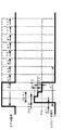
この記録パルス生成回路5で生成される記録パルスの例を図2に示す。
図2に示す記録パルスおいて、ODT1とODT2は、記録しようとする3T〜11Tの記録パルス出力期間において、
0T≦OTD1≦3.0T,Pw*0.0≦ΔP1≦Pw*0.5
0T≦OTD2≦3.0T,Pw*0.0≦ΔP2≦Pw*0.5
の範囲で可変設定される。ここで、ODT1とODT2、ΔP1とΔP2は、
ODT1≧ODT2
ΔP1≧ΔP2
なる関係とする。
【0019】
また、記録パルスODT1,ODT2は、
ODT1(3T)≧ODT1(4T)≧・・・ODT1(11T)
ODT2(3T)≧ODT2(4T)≧・・・ODT2(11T)
なる関係を保持する状態でであれば3T〜11Tの記録パルスにそれぞれに対して独立に出力期間を可変することも可能である。
【0020】
ここで、光ディスクなどの記録媒体に対して光変調記録方式で記録を行う場合には、記録しようとするピットの直前にくるランド(スペース)の長さが短いほど、その前のピット(マーク)を記録した際に蓄積された熱が十分に放熱されていないために熱干渉が発生し易い。そこで、この記録パルス生成回路5では、記録しようとするピット(マーク)、ランド(スペース)の組み合わせにより、それぞれのパルスについて独立かつ任意にパルス長を可変することで、記録後の再生信号が最良となるように記録パルス長を変化させることも可能である。
【0021】
上記記録パルス生成回路5で生成された各記録パルスは、光学ヘッド3に内蔵されたレーザ駆動用のレーザドライバ回路31に供給される。レーザドライバ回路31により記録パルスの論理に従いレーザダイオードを駆動して記録レーザを発光させることで、光ディスク1にデータの記録が行われる。
【0022】
ここで、記録ストラテジ処理を施してEQEFM記録パルスV1の略前端に2段階の積み重ね部分ΔP1,ΔP2を重畳させた記録パルスを生成する記録パルス生成回路5は、例えば図3に示すように、ピット/ランド長検出回路51、EQEFM生成回路52、ODP1生成回路53及びODP2生成回路54を備える。
【0023】
この記録パルス生成回路5において、ピット/ランド長検出回路51は、エンコーダ/デコーダ回路7から供給されるEFM信号のパルス幅や直前のピット長、ランド長を検出する。そして、EQEFM生成回路52では、EFM信号に基づいた所定のレベル及びパルス幅のEQEFM記録パルスV1を生成し、ODP1生成回路53では、レーザ駆動パルスの略前端に付加されることになるODP1記録パルスV2を生成し、ODP2生成回路54を備える。レーザ駆動パルスの略前端に付加されることになるODP2記録パルスV3を生成する。上記EQEFM生成回路52、ODP1生成回路53及びODP2生成回路54により生成される各記録パルスV1,V2,V3は、ピット/ランド長検出回路51によって検出されたEFM信号のパルス幅や直前のピット長、ランド長に応じてパルス幅やパルスレベル(電圧レベル)が可変制御される。
【0024】
上記記録パルス生成回路5で生成された各記録パルスV1,V2,V3は、光学ヘッド3に内蔵されたレーザ駆動用のレーザドライバ回路30に供給される。レーザドライバ回路30により各記録パルスの論理に従いレーザダイオードLDを駆動して記録レーザを発光させることで、光ディスク1にデータの記録が行われる。上記レーザドライバ回路30では、上記EQEFM生成回路52、ODP1生成回路53及びODP2生成回路54により生成された各記録パルスV1,V2,V3が電圧/電流変換回路31,32,33によって記録電流信号I1,I2,I3に変換されて、各記録電流信号I1,I2,I3が加算回路34によって加算合成される。そして、この加算回路34により各記録電流信号I1,I2,I3を加算合成して得られる駆動電流i(=I1+I2+I3)をレーザダイオードLDに流すことによって、上記レーザダイオードLDを駆動して記録レーザを発光させ、光ディスク1にデータを記録する。
【0025】
すなわち、この記録パルス生成回路5では、図4に示すように、上記記録パルス生成回路5で生成された各記録パルスV1,V2,V3を電流値として加算した駆動電流iをレーザダイオードLDに流し、EQEFM信号の略前端に2段階の積み重ね部分ΔP1,ΔP2を有する発光波形の記録レーザを上記レーザダイオードLDから光ディスク1の記録面に照射することにより、上記記録面上にピットとランドからなるトラックを形成する。
【0026】
この図4において、期間Cは、レーザ発光がオンとなってからピットの形成が開始されるまでの時間遅れを示し、また、期間cはレーザ発光がオフとなってからピットの形成が終了されるまでの時間遅れを示す。上記期間C及び期間cは、
C<B<A
c<b<a
すなわち、従来の1倍速記録時及び2倍速記録時の記録ストラテジを採用して記録を行った場合の図13に示した期間A及び期間a、また、従来の4倍速記録時の記録ストラテジを採用して記録を行った場合の図14に示した期間B及び期間bよりも短い期間となる。
【0027】
このように本発明に係る光ディスク記録再生装置100では、高速記録時におけるEFM信号に精度良く対応したピット/ランドを形成することができる。
ここで、この光ディスク記録再生装置100では、EQEFM記録パルスV1にODP1記録パルスV2とODP2記録パルスV3を加算することにより駆動電流iが生成されるのであるが、各記録パルスV1,V2,V3は、記録条件や上記ピット/ランド長検出回路51により検出されるEFM信号のパルス幅や直前のピット長、ランド長に応じてレベルやパルス幅が可変され、また、3T〜11Tのそれぞれに応じてパルス幅を任意にかつ独立して可変設定される。つまり、パルス幅の違い(レーザ照射期間の差によって生ずる記録トラック上の熱蓄積の違い)に応じてパルス幅を制御することになり、これによりEFM信号に精度良く対応したピット/ランドを形成することができる。
【0028】
実際には、ディスクの材質(色素膜の材質)、製造メーカ、記録線速度、記録速度、光学ヘッドの光学的特性などの諸条件によっても、パルス幅やパルスレベルを調整する。
【0029】
特に、色素膜の材質の違いなどによって熱反応の違いがあるため、記録動作の際に装填されているディスクの種別や製造メーカを判断して、パルス幅やパルスレベルを調整することは有効である。また、記録開始後にパルス幅やパルスレベルを調整することも記録動作に有効となる。
【0030】
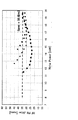
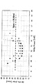
ここで、シアニン系ディスク及びフタロシアニン系ディスクについて、再生3Tピット/ランドジッタの特性を実測したところ、図5乃至図8に示しような実測結果が得られた。
【0031】
図5及び図6は、シアニン系有機色素が塗布されたCD−Rメディアに対して8倍速記録して得られた再生3Tピットジッタ特性及び再生3Tランドジッタ特性の実測結果を示している。また、図7及び図8は、フタロシアニン系有機色素が塗布されたCD−Rディスクに対して8倍速記録して得られた再生3Tピットジッタ特性及び再生3Tランドジッタ特性の実測結果を示している。実測結果として得られた再生3Tピットジッタ特性及び再生3Tランドジッタ特性を示している。図5乃至図8において、横軸は記録パワーを示し、縦軸は再生RF信号に含まれるRFジッタを示している。
【0032】
図5乃至図8には、図10に示した従来の1倍速記録時及び2倍速記録時の記録ストラテジを採用し、θ=0.25、α=0.13Tとして記録した場合の実測結果を■印にて示し、図11に示した従来の4倍速記録時及び2倍速記録時の記録ストラテジを採用し、θ=0.25、α=1.50T、ΔP=30%として記録した場合の実測結果を▲印にて示し、本発明に係る光ディスク記録再生装置100による各記録パルスのパルス長さ等を最適化して記録した場合の実測結果を●印で示してある。
【0033】
上記図5乃至図8に示す再生3Tピット/ランドジッタの特性の実測結果からも明らかなように、本発明に係る光ディスク記録再生装置100によれば、記録するメディアの有機色素の材料を問わず、記録後のピット/ランドジッタが大幅に改善され、かつ、記録パワーにに対するジッタのパワーマージン、記録パワーの低下も大幅に改善することができる。
【0034】
ここで、上記光ディスク記録再生装置100では、EQEFM記録パルスV1の略前端に2段階の積み重ね部分ΔP1,ΔP2を有する波形の記録レーザを発光するようにしたが、図9に示すように、上記記録パルス生成回路5でEQEFM記録パルスV1とm種類のパルス幅L1〜LmのODP1記録パルスV1〜ODPm記録パルスVmを生成して、EQEFM記録パルスV1の略前端にm段階の積み重ね部分ΔP1〜ΔPmを有する波形の記録レーザを発光させて記録を行う記録ストラテジを採用することもできる。
【0035】
【発明の効果】
以上のように、本発明によれば、形成するピット長に応じたパルス幅を有し、略前端部分の記録パワーを複数段に亘る階段状に設定した記録パルスを生成し、上記記録パルスによりパルス発光されるレーザ光を照射し記録を行うことにより、記録する符号間(ピット/ランド)の干渉による熱干渉を低減することができ、例えば8倍速などの高速記録時にも十分な再生マージンを得ることができる適切な形状のピット/ランドを形成することができる。また、記録ジッタの低減により記録品質の向上を図ることができる。
【0036】
すなわち、本発明によれば、8倍速記録や12倍速記録など4倍速よりも速い速度で適正なピット形状の記録を行うことができる。
【図面の簡単な説明】
【図1】本発明を適用した光ディスク記録再生装置の構成を示すブロック図である。
【図2】上記光ディスク記録再生装置において採用される記録ストラテジを示す波形図である。
【図3】上記光ディスク記録再生装置において記録パルス生成回路の具体的な構成例を示すブロック図である。
【図4】上記光ディスク記録再生装置による記録動作を示す波形図である。
【図5】シアニン系有機色素が塗布されたCD−Rディスクに対して8倍速記録して得られた再生3Tピットジッタ特性の実測結果を示す図である。
【図6】シアニン系有機色素が塗布されたCD−Rディスクに対して8倍速記録して得られた再生3Tランドジッタ特性の実測結果を示す図である。
【図7】フタロシアニン系有機色素が塗布されたCD−Rディスクに対して8倍速記録して得られた再生3Tピットジッタ特性の実測結果を示す図である。
【図8】フタロシアニン系有機色素が塗布されたCD−Rディスクに対して8倍速記録して得られた再生3Tランドジッタ特性の実測結果を示す図である。
【図9】上記光ディスク記録再生装置において採用される記録ストラテジの変形例を示す波形図である。
【図10】オレンジブック規格で規定されている1倍速記録時及び2倍速記録時の記録ストラテジを示す波形図である。
【図11】オレンジブック規格で規定されている4倍速記録時の記録ストラテジを示す波形図である。
【図12】理想的な記録状態を示す図である。
【図13】上記1倍速記録時及び2倍速記録時の記録ストラテジにより8倍速記録を行った場合のピットの歪みを示す図である。
【図14】上記4倍速記録時の記録ストラテジにより8倍速記録を行った場合のピットの歪みを示す図である。
【符号の説明】
1 光ディスク、2 ピンドルモータ、3 光学ヘッド、4 サーボ回路、5記録パルス生成回路、6 再生信号処理回路、7 エンコーダ/デコーダ回路、8 SCSIインターフェース回路、9 システムコントローラ、10 ホストコンピュータ、30 レーザドライバ回路、31,32,33 電圧/電流変換回路、34 加算回路、51 ピット/ランド長検出回路、52 EQEFM生成回路、53 ODP1生成回路、54 ODP2生成回路、LD レーザダイオード、100 光ディスク記録再生装置[0001]
BACKGROUND OF THE INVENTION
The present invention relates to a mark length recording type optical disc recording apparatus that records information by irradiating a recording surface of an optical disc with a laser beam, and in particular, a speed higher than 4 × speed such as 8 × speed recording or 12 × speed recording. The present invention relates to an optical disc recording apparatus and an optical disc recording method for performing recording in the above.
[0002]
[Prior art]
Conventionally, when optical modulation system recording is performed on a recording medium such as an optical disk, thermal control is performed by causing a laser to emit light in order to satisfactorily form pits (marks) formed on the disk. I am doing so. Specifically, a pulse waveform is set as a drive pulse for driving the laser, and the level (crest value) of each pulse period is also controlled to control the laser power and the laser irradiation period.
[0003]
For example, in an optical recording / reproducing apparatus typified by CD-R (CD-Recordable) or CD-RW (CD-ReWritable), the laser beam to be irradiated depends on the recording mark length (or space length) to be recorded. A pulse length recording method or a pulse train recording method is employed in which the laser power output section is controlled by varying the pulse length or the number of pulses.
[0004]
In the Orange Book Standard (Orange-Book Part2 (Version 3.1)), which is the latest standard for CD-R, the standard itself assumes 1x speed recording, 2x speed recording, and 4x speed recording, depending on the writing speed at that time. Laser emission control (recording strategy (recording compensation)) is defined as shown in FIGS. That is, in the CD-R standard, information is recorded on the optical disc by a combination of 3T to 11T pits (marks) and lands (spaces), and the recording strategy at the time of 1 × speed recording and 2 × speed recording is as shown in FIG. In addition, a laser power output section of (n−θ) T + αT is defined, where Pw is a laser power for forming nT pits (marks). However, θ = 1T and α = 0.13T. As shown in FIG. 11, the recording strategy at the time of quadruple speed recording is such that the laser power for forming nT pits (marks) is Pw + ΔP, (n−θ) T is the output section of the laser power (Pw), and , ODT is defined as the output section of the laser power (ΔP). Here, ΔP is 20% to 30% of Pw, and ODT is 1.25T to 1.5T.
[0005]
[Problems to be solved by the invention]
By the way, if the recording strategy based on the Orange Book standard on the premise of 1 × speed recording, 2 × speed recording and 4 × speed recording is applied when recording at a speed higher than 4 × speed such as 8 × speed recording or 12 × speed recording, it will be recorded. As a result, thermal interference occurs between the pit / land codes, and the quality of the recording signal deteriorates due to deformation of the pit shape or deterioration of jitter.
[0006]
That is, as shown in FIG. 12, the ideal relationship between recording data and pits is that nT-length pits are formed in the shape of an ellipse with respect to nT recording data. When, for example, 8 × speed recording is performed with the recording strategy at the time and 2 × speed recording, as shown in FIG. 13, tear-shaped pits whose end side extends in a direction perpendicular to the track center are formed, and 4 If the recording strategy at the time of double speed recording is employed, tear-shaped pits with slightly improved spread in the orthogonal direction are formed as shown in FIG.
[0007]
Here, in FIGS. 13 and 14, period A and period B indicate time delays from when laser emission is turned on until pit formation is started, respectively, and period a and period b period c are Time delays from when the laser emission is turned off until the pit formation is finished are shown.
[0008]
As described above, when the quality of the recording signal is deteriorated due to the deformation of the pit shape, the deterioration of jitter, or the like, there is a possibility that the reproduction cannot be normally performed.
[0009]
Accordingly, an object of the present invention is to make it possible to record an appropriate pit shape at a speed faster than 4 × speed, such as 8 × speed recording or 12 × speed recording, in view of the conventional problems as described above. .
[0010]
[Means for Solving the Problems]
An optical disc recording apparatus according to the present invention includes a pit / land length detection unit that detects a length of a pit / land formed on an optical disc from an input signal, a first recording pulse generation unit that generates a first recording pulse, A second recording pulse generating means for generating a second recording pulse to be added to a substantially front end of the first recording pulse generated by the first recording pulse generating means; and a second recording pulse generating means. Third recording pulse generating means for generating a third recording pulse to be added to substantially the front end of the generated second recording pulse, the first recording pulse, the second recording pulse, and the the third level of the recording pulse, and pulse width are each independently be variably set according to the combination of the length of the pits / lands detected by the pit / land length detection means And features.
[0011]
The optical disc recording method according to the present invention includes a pit / land length detection step for detecting the length of a pit / land formed on an optical disc from an input signal, and a first recording pulse generation step for generating a first recording pulse. A second recording pulse generating step for generating a second recording pulse to be added to substantially the front end of the first recording pulse generated in the first recording pulse generating step, and the second recording pulse generation A third recording pulse generating step for generating a third recording pulse to be added to substantially the front end of the second recording pulse generated in the step, the first recording pulse, the second recording pulse, The level of the third recording pulse and the pulse width can be independently set according to the combination of pit / land lengths detected in the pit / land length detection step. Characterized in that it is set.
[0012]
DETAILED DESCRIPTION OF THE INVENTION
Hereinafter, embodiments of the present invention will be described in detail with reference to the drawings.
[0013]
The present invention is applied to, for example, an optical disc recording / reproducing
[0014]
An optical disc recording / reproducing
[0015]
The
[0016]
In the optical disc recording / reproducing
[0017]
In the recording
[0018]
An example of the recording pulse generated by the recording
In the recording pulse shown in FIG. 2, ODT1 and ODT2 are in the recording pulse output period of 3T to 11T to be recorded.
0T ≦ OTD1 ≦ 3.0T, Pw * 0.0 ≦ ΔP1 ≦ Pw * 0.5
0T ≦ OTD2 ≦ 3.0T, Pw * 0.0 ≦ ΔP2 ≦ Pw * 0.5
It is variably set within the range. Here, ODT1 and ODT2, and ΔP1 and ΔP2 are
ODT1 ≧ ODT2
ΔP1 ≧ ΔP2
It becomes the relation which becomes.
[0019]
The recording pulses ODT1, ODT2 are
ODT1 (3T) ≧ ODT1 (4T) ≧ ・ ・ ・ ODT1 (11T)
ODT2 (3T) ≧ ODT2 (4T) ≧ ・ ・ ・ ODT2 (11T)
If the relationship holds, the output period can be varied independently for each of the 3T to 11T recording pulses.
[0020]
Here, when recording is performed on a recording medium such as an optical disk by the optical modulation recording method, the shorter the land (space) that comes immediately before the pit to be recorded, the shorter the pit (mark) in front of it. Since the heat accumulated when recording is not sufficiently dissipated, thermal interference is likely to occur. Therefore, in this recording
[0021]
Each recording pulse generated by the recording
[0022]
Here, the recording
[0023]
In this recording
[0024]
The recording pulses V1, V2, and V3 generated by the recording
[0025]
That is, in the recording
[0026]
In FIG. 4, a period C indicates a time delay from when the laser emission is turned on until pit formation is started, and a period c is the end of the pit formation after the laser emission is turned off. Indicates the time delay until The period C and the period c are
C <B <A
c <b <a
That is, the period A and the period a shown in FIG. 13 when recording is performed using the recording strategy at the time of conventional 1 × speed recording and 2 × speed recording, and the recording strategy at the time of conventional 4 × speed recording is employed. Thus, the recording period is shorter than the period B and the period b shown in FIG.
[0027]
As described above, the optical disc recording / reproducing
Here, in this optical disc recording / reproducing
[0028]
Actually, the pulse width and the pulse level are adjusted according to various conditions such as the material of the disk (material of the dye film), the manufacturer, the recording linear velocity, the recording velocity, and the optical characteristics of the optical head.
[0029]
In particular, because there is a difference in the thermal reaction due to the difference in the material of the dye film, etc., it is effective to adjust the pulse width and pulse level by judging the type and manufacturer of the disc loaded during the recording operation. is there. In addition, adjusting the pulse width and pulse level after the start of recording is also effective for the recording operation.
[0030]
Here, when the
[0031]
FIG. 5 and FIG. 6 show the measurement results of the
[0032]
FIGS. 5 to 8 show the actual measurement results when recording is performed with θ = 0.25 and α = 0.13T, using the recording strategy at the time of the conventional 1 × speed recording and 2 × speed recording shown in FIG. When the conventional 4 × speed recording and 2 × speed recording strategies shown in FIG. 11 are employed and θ = 0.25, α = 1.50T, and ΔP = 30% The actual measurement results are indicated by ▲, and the actual measurement results when the optical disc recording / reproducing
[0033]
As is apparent from the measurement results of the
[0034]
Here, in the optical disc recording / reproducing
[0035]
【The invention's effect】
As described above, according to the present invention, a recording pulse having a pulse width corresponding to the pit length to be formed and having a recording power at a substantially front end portion set in a stepped shape over a plurality of steps is generated, and the recording pulse is By performing recording by irradiating pulsed laser light, it is possible to reduce thermal interference caused by interference between recording codes (pits / lands). For example, sufficient reproduction margin can be obtained even at high speed recording such as 8 × speed. A pit / land of an appropriate shape that can be obtained can be formed. Further, the recording quality can be improved by reducing the recording jitter.
[0036]
That is, according to the present invention, it is possible to perform recording of an appropriate pit shape at a speed faster than 4 × speed, such as 8 × speed recording or 12 × speed recording.
[Brief description of the drawings]
FIG. 1 is a block diagram showing a configuration of an optical disc recording / reproducing apparatus to which the present invention is applied.
FIG. 2 is a waveform diagram showing a recording strategy employed in the optical disc recording / reproducing apparatus.
FIG. 3 is a block diagram showing a specific configuration example of a recording pulse generation circuit in the optical disc recording / reproducing apparatus.
FIG. 4 is a waveform diagram showing a recording operation by the optical disc recording / reproducing apparatus.
FIG. 5 is a diagram showing an actual measurement result of
FIG. 6 is a diagram showing an actual measurement result of
FIG. 7 is a diagram showing an actual measurement result of reproduced 3T pit jitter characteristics obtained by recording at 8 × speed on a CD-R disc coated with a phthalocyanine-based organic dye.
FIG. 8 is a diagram showing an actual measurement result of a reproduced 3T land jitter characteristic obtained by recording at 8 × speed on a CD-R disc coated with a phthalocyanine organic dye.
FIG. 9 is a waveform diagram showing a modification of the recording strategy employed in the optical disc recording / reproducing apparatus.
FIG. 10 is a waveform diagram showing a recording strategy at the time of 1 × speed recording and 2 × speed recording specified in the Orange Book standard.
FIG. 11 is a waveform diagram showing a recording strategy at the time of quadruple speed recording defined by the Orange Book standard.
FIG. 12 is a diagram illustrating an ideal recording state.
FIG. 13 is a diagram showing distortion of pits when 8 × speed recording is performed according to the recording strategy at the time of 1 × speed recording and 2 × speed recording.
FIG. 14 is a diagram showing pit distortion when 8 × recording is performed according to the recording strategy at the time of 4 × recording.
[Explanation of symbols]
1 optical disk, 2 pindle motor, 3 optical head, 4 servo circuit, 5 recording pulse generation circuit, 6 reproduction signal processing circuit, 7 encoder / decoder circuit, 8 SCSI interface circuit, 9 system controller, 10 host computer, 30 laser driver circuit , 31, 32, 33 Voltage / current conversion circuit, 34 adder circuit, 51 pit / land length detection circuit, 52 EQEFM generation circuit, 53 ODP1 generation circuit, 54 ODP2 generation circuit, LD laser diode, 100 optical disk recording / reproducing apparatus
Claims (2)
第1の記録パルスを生成する第1の記録パルス生成手段と、
前記第1の記録パルス生成手段によって生成された第1の記録パルスの略前端に付加される第2の記録パルスを生成する第2の記録パルス生成手段と、
前記第2の記録パルス生成手段によって生成される第2の記録パルスの略前端に付加される第3の記録パルスを生成する第3の記録パルス生成手段とを備え、
前記第1の記録パルス、前記第2の記録パルス、及び前記第3の記録パルスのレベル、及びパルス幅は、前記ピット/ランド長検出手段によって検出されたピット/ランドの長さの組み合わせに応じて各々独立して可変設定される光ディスク記録装置。 Pit / land length detecting means for detecting the length of the pit / land formed on the optical disc from the input signal;
First recording pulse generating means for generating a first recording pulse ;
Second recording pulse generating means for generating a second recording pulse to be added to substantially the front end of the first recording pulse generated by the first recording pulse generating means;
Third recording pulse generating means for generating a third recording pulse to be added to substantially the front end of the second recording pulse generated by the second recording pulse generating means,
The levels and pulse widths of the first recording pulse, the second recording pulse, and the third recording pulse are in accordance with the combination of the pit / land lengths detected by the pit / land length detecting means. An optical disk recording device that is variably set independently.
第1の記録パルスを生成する第1の記録パルス生成ステップと、
前記第1の記録パルス生成ステップで生成された第1の記録パルスの略前端に付加される第2の記録パルスを生成する第2の記録パルス生成ステップと、
前記第2の記録パルス生成ステップで生成される第2の記録パルスの略前端に付加される第3の記録パルスを生成する第3の記録パルス生成ステップとを含み、
前記第1の記録パルス、前記第2の記録パルス、及び前記第3の記録パルスのレベル、及びパルス幅は、前記ピット/ランド長検出ステップで検出されたピット/ランドの長さの組み合わせに応じて各々独立して可変設定される光ディスク記録方法。 A pit / land length detecting step for detecting the length of the pit / land formed on the optical disc from the input signal;
A first recording pulse generating step for generating a first recording pulse ;
A second recording pulse generating step for generating a second recording pulse to be added to substantially the front end of the first recording pulse generated in the first recording pulse generating step;
A third recording pulse generating step for generating a third recording pulse to be added to the substantially front end of the second recording pulse generated in the second recording pulse generating step,
The levels and pulse widths of the first recording pulse, the second recording pulse, and the third recording pulse depend on the combination of the pit / land lengths detected in the pit / land length detection step. An optical disc recording method in which each is independently variably set.
Priority Applications (11)
| Application Number | Priority Date | Filing Date | Title |
|---|---|---|---|
| JP2000183780A JP4419285B2 (en) | 2000-06-19 | 2000-06-19 | Optical disc recording apparatus and optical disc recording method |
| TW090113840A TWI227022B (en) | 2000-06-19 | 2001-06-07 | Optical disk recorder and optical disk recording method |
| MYPI20012819A MY128433A (en) | 2000-06-19 | 2001-06-15 | Optical disc recording method and apparatus. |
| KR1020010033937A KR100779704B1 (en) | 2000-06-19 | 2001-06-15 | Optical disc recording method and apparatus |
| IDP00200100463D ID30535A (en) | 2000-06-19 | 2001-06-18 | METHODS AND APARATUS OPTIMIST RECORDING RECORDERS |
| US09/881,676 US6819644B2 (en) | 2000-06-19 | 2001-06-18 | Optical disc recording method and apparatus |
| CNB01124321XA CN1165039C (en) | 2000-06-19 | 2001-06-19 | Optical disc recording method and device |
| DE60120844T DE60120844T2 (en) | 2000-06-19 | 2001-06-19 | Optical disc recording method and apparatus |
| DE60131473T DE60131473T2 (en) | 2000-06-19 | 2001-06-19 | Optical disk recording method and apparatus |
| EP01114669A EP1174862B1 (en) | 2000-06-19 | 2001-06-19 | Optical disc recording method and apparatus |
| EP05022615A EP1615211B1 (en) | 2000-06-19 | 2001-06-19 | Optical disc recording method and apparatus |
Applications Claiming Priority (1)
| Application Number | Priority Date | Filing Date | Title |
|---|---|---|---|
| JP2000183780A JP4419285B2 (en) | 2000-06-19 | 2000-06-19 | Optical disc recording apparatus and optical disc recording method |
Publications (2)
| Publication Number | Publication Date |
|---|---|
| JP2002008238A JP2002008238A (en) | 2002-01-11 |
| JP4419285B2 true JP4419285B2 (en) | 2010-02-24 |
Family
ID=18684305
Family Applications (1)
| Application Number | Title | Priority Date | Filing Date |
|---|---|---|---|
| JP2000183780A Expired - Fee Related JP4419285B2 (en) | 2000-06-19 | 2000-06-19 | Optical disc recording apparatus and optical disc recording method |
Country Status (9)
| Country | Link |
|---|---|
| US (1) | US6819644B2 (en) |
| EP (2) | EP1174862B1 (en) |
| JP (1) | JP4419285B2 (en) |
| KR (1) | KR100779704B1 (en) |
| CN (1) | CN1165039C (en) |
| DE (2) | DE60120844T2 (en) |
| ID (1) | ID30535A (en) |
| MY (1) | MY128433A (en) |
| TW (1) | TWI227022B (en) |
Families Citing this family (22)
| Publication number | Priority date | Publication date | Assignee | Title |
|---|---|---|---|---|
| JP3521141B2 (en) * | 2002-01-08 | 2004-04-19 | 株式会社リコー | Information recording device |
| JP2005518619A (en) * | 2002-02-22 | 2005-06-23 | コーニンクレッカ フィリップス エレクトロニクス エヌ ヴィ | Method and apparatus for recording marks on the recording surface of an optical record carrier, and optical record carrier therefor |
| JP2003338038A (en) * | 2002-05-17 | 2003-11-28 | Tdk Corp | Method and apparatus for recording information on optical recording medium, and optical recording medium |
| US6954415B2 (en) * | 2002-07-03 | 2005-10-11 | Ricoh Company, Ltd. | Light source drive, optical information recording apparatus, and optical information recording method |
| AU2003250421A1 (en) * | 2002-08-14 | 2004-03-03 | Koninklijke Philips Electronics N.V. | Method and apparatus for recording marks in a phase-change type information layer of a record carrier |
| AU2003275691A1 (en) * | 2002-10-28 | 2004-05-13 | Matsushita Electric Industrial Co., Ltd. | Optical information recording method, optcal information recording device and optica information recording medium |
| KR100521909B1 (en) | 2002-12-26 | 2005-10-13 | 주식회사 히타치엘지 데이터 스토리지 코리아 | An apparatus and method for driving laser diode |
| KR20060054276A (en) * | 2003-07-03 | 2006-05-22 | 코닌클리케 필립스 일렉트로닉스 엔.브이. | Method and apparatus for recording marks on a write-once record carrier |
| EP1923870A3 (en) * | 2003-08-14 | 2008-07-30 | LG Electronics Inc. | Method of configuring control information of a recording medium, recording and reproducing method using the same, and apparatus thereof |
| JP3732499B2 (en) | 2003-08-26 | 2006-01-05 | 株式会社リコー | Dye-type recordable DVD medium recording / reproducing method and apparatus |
| US7480223B2 (en) * | 2004-01-30 | 2009-01-20 | Ricoh Company, Ltd. | Recording and reading method and device for dye based write-once DVD medium |
| TWI327311B (en) * | 2004-03-10 | 2010-07-11 | Ricoh Co Ltd | Apparatus and process for recording dye based recordable dvd media, media recorded information by apparatus, and apparatus for regenerating the information |
| CN1734584A (en) * | 2004-08-13 | 2006-02-15 | 皇家飞利浦电子股份有限公司 | Method and apparatus for determining parameter for CD recording |
| JP2006092664A (en) * | 2004-09-24 | 2006-04-06 | Ricoh Co Ltd | Optical information recording device |
| EP1688930A1 (en) * | 2005-02-08 | 2006-08-09 | Ricoh Company, Ltd. | Dye-based recordable DVD medium, and method and apparatus for recording and reproducing thereof |
| US8369199B2 (en) * | 2005-02-17 | 2013-02-05 | Mediatek Inc. | Methods and systems for tuning at least one write strategy parameter of an optical storage device |
| US7006420B1 (en) * | 2005-02-17 | 2006-02-28 | Mediatek Incorporation | Method for tuning write strategy parameters of an optical storage device, and system thereof |
| JP2006309881A (en) * | 2005-04-28 | 2006-11-09 | Samsung Electronics Co Ltd | Optical information recording device and optical information recording method |
| JP4339820B2 (en) * | 2005-05-30 | 2009-10-07 | 太陽誘電株式会社 | Optical information recording apparatus and method, and signal processing circuit |
| US7773479B1 (en) | 2005-10-12 | 2010-08-10 | Marvell International Ltd. | Flexible optical write strategy |
| EP1837869A3 (en) * | 2006-03-24 | 2008-03-05 | Samsung Electronics Co., Ltd. | Recording method, recording apparatus, and optical recording medium |
| JP5336155B2 (en) * | 2007-12-26 | 2013-11-06 | 太陽誘電株式会社 | Optical information recording apparatus and method |
Family Cites Families (22)
| Publication number | Priority date | Publication date | Assignee | Title |
|---|---|---|---|---|
| JP2605015B2 (en) * | 1985-06-26 | 1997-04-30 | インターナショナル・ビジネス・マシーンズ・コーポレーション | Information-bearing signal recorder for thermal induction recording |
| KR910003460B1 (en) * | 1987-02-12 | 1991-05-31 | 가부시기가이샤 히다찌세이사꾸쇼 | Optical information-recording apparatus |
| JP2702942B2 (en) * | 1987-11-02 | 1998-01-26 | 日本電信電話株式会社 | Optical disk recording method |
| JP2845915B2 (en) * | 1989-01-06 | 1999-01-13 | 株式会社日立製作所 | Information reproducing method and information reproducing apparatus |
| JPH0810490B2 (en) | 1989-03-20 | 1996-01-31 | 富士通株式会社 | Optical disk information writing control method and apparatus therefor |
| JP2852792B2 (en) * | 1990-07-05 | 1999-02-03 | 三菱電機株式会社 | Optical disk drive |
| JPH04209318A (en) | 1990-11-30 | 1992-07-30 | Sharp Corp | Optical information recording and reproducing device |
| US5297129A (en) * | 1992-12-24 | 1994-03-22 | Optical Disc Corporation | Waveform shaping method and apparatus for optical recording |
| JP2674453B2 (en) * | 1993-01-18 | 1997-11-12 | 日本電気株式会社 | Optical disc medium recording method and apparatus |
| JPH06274889A (en) * | 1993-01-20 | 1994-09-30 | Mitsubishi Electric Corp | Optical recorder |
| US5490126A (en) * | 1993-04-07 | 1996-02-06 | Matsushita Electric Industrial Co., Ltd. | Apparatus for recording and reproducing data on a disk |
| JPH09330519A (en) * | 1996-06-10 | 1997-12-22 | Hitachi Ltd | Optical-disk recording and reproducing device |
| JP3366973B2 (en) * | 1996-10-18 | 2003-01-14 | 富士通株式会社 | Information recording method for optical recording medium |
| JPH11102522A (en) | 1997-09-29 | 1999-04-13 | Nec Corp | Optical information recording method and optical information recording device |
| US6781937B2 (en) * | 1998-01-21 | 2004-08-24 | Yamaha Corporation | Optical disk recording method and device |
| JP3470584B2 (en) * | 1998-03-05 | 2003-11-25 | ヤマハ株式会社 | Optical disk recording method and apparatus |
| JP2000149265A (en) * | 1998-08-04 | 2000-05-30 | Hitachi Ltd | Information recording method, information recording medium, and information recording device |
| TW468177B (en) * | 1998-08-04 | 2001-12-11 | Hitachi Ltd | Data storage method, data storage medium and data storage recording device |
| JP2000187842A (en) * | 1998-12-21 | 2000-07-04 | Taiyo Yuden Co Ltd | Method and device for optical information recording |
| JP2000215449A (en) * | 1999-01-27 | 2000-08-04 | Taiyo Yuden Co Ltd | Method and device for recording optical information |
| JP3298547B2 (en) * | 1999-03-30 | 2002-07-02 | ヤマハ株式会社 | Optical disk recording device |
| EP1117094B1 (en) | 2000-01-17 | 2012-11-21 | Mitsubishi Kagaku Media Co., Ltd. | Recording method for phase-change recording medium |
-
2000
- 2000-06-19 JP JP2000183780A patent/JP4419285B2/en not_active Expired - Fee Related
-
2001
- 2001-06-07 TW TW090113840A patent/TWI227022B/en not_active IP Right Cessation
- 2001-06-15 KR KR1020010033937A patent/KR100779704B1/en not_active IP Right Cessation
- 2001-06-15 MY MYPI20012819A patent/MY128433A/en unknown
- 2001-06-18 US US09/881,676 patent/US6819644B2/en not_active Expired - Fee Related
- 2001-06-18 ID IDP00200100463D patent/ID30535A/en unknown
- 2001-06-19 CN CNB01124321XA patent/CN1165039C/en not_active Expired - Fee Related
- 2001-06-19 EP EP01114669A patent/EP1174862B1/en not_active Expired - Lifetime
- 2001-06-19 DE DE60120844T patent/DE60120844T2/en not_active Expired - Lifetime
- 2001-06-19 EP EP05022615A patent/EP1615211B1/en not_active Expired - Lifetime
- 2001-06-19 DE DE60131473T patent/DE60131473T2/en not_active Expired - Lifetime
Also Published As
| Publication number | Publication date |
|---|---|
| MY128433A (en) | 2007-02-28 |
| DE60131473T2 (en) | 2008-11-06 |
| JP2002008238A (en) | 2002-01-11 |
| EP1615211B1 (en) | 2007-11-14 |
| EP1174862A2 (en) | 2002-01-23 |
| KR100779704B1 (en) | 2007-11-26 |
| CN1165039C (en) | 2004-09-01 |
| EP1615211A1 (en) | 2006-01-11 |
| TWI227022B (en) | 2005-01-21 |
| US6819644B2 (en) | 2004-11-16 |
| DE60131473D1 (en) | 2007-12-27 |
| EP1174862B1 (en) | 2006-06-21 |
| DE60120844T2 (en) | 2006-12-21 |
| US20020021642A1 (en) | 2002-02-21 |
| EP1174862A3 (en) | 2004-02-04 |
| ID30535A (en) | 2001-12-20 |
| CN1340810A (en) | 2002-03-20 |
| KR20010113511A (en) | 2001-12-28 |
| DE60120844D1 (en) | 2006-08-03 |
Similar Documents
| Publication | Publication Date | Title |
|---|---|---|
| JP4419285B2 (en) | Optical disc recording apparatus and optical disc recording method | |
| US6704269B1 (en) | Optical disk recording apparatus | |
| US7123566B2 (en) | Recording apparatus and recording method | |
| US6480450B1 (en) | Method and apparatus for recording optical information by varying recording pulse width | |
| US6996047B2 (en) | Optical disc recording method and apparatus | |
| JP2005004906A (en) | Method and device for recording information | |
| US6487152B1 (en) | Method of recording information in phase-change recording medium and recording medium for use in the method | |
| EP1347444B1 (en) | Method and apparatus for recording data on optical recording medium | |
| US20060044968A1 (en) | Optical information recording method, optical information recording device and optical information recording medium | |
| US20030235128A1 (en) | Information recording and reproducing apparatus, and information recording method | |
| JP4405115B2 (en) | Information recording apparatus and information recording method | |
| JP4336646B2 (en) | Information recording apparatus and information recording method | |
| US8040771B2 (en) | Optical disc apparatus and method for controlling overwrite power | |
| JP2004234699A (en) | Recording waveform control method of optical disk, and optical disk device using the method | |
| JP4231871B2 (en) | Information recording apparatus and information recording method | |
| JP2004014101A (en) | Method for recording data in optical recording medium and its device | |
| JP2000163748A (en) | Information recording system and information recording and reproducing device | |
| JPH07129960A (en) | Optical disk recorder | |
| JP2005004905A (en) | Method and device for recording information | |
| JP2601116B2 (en) | Optical disk recording device | |
| WO2005041175A1 (en) | Information recording device and information recording method | |
| WO2000074045A1 (en) | Optical information recording method, optical information recording device and optical information recording medium | |
| JP2000057571A (en) | Optical disk recording device | |
| KR19980021833A (en) | Method of controlling the recording light source of the optical recording device | |
| JP2005228440A (en) | Optical disk unit |
Legal Events
| Date | Code | Title | Description |
|---|---|---|---|
| A621 | Written request for application examination |
Free format text: JAPANESE INTERMEDIATE CODE: A621 Effective date: 20070611 |
|
| A977 | Report on retrieval |
Free format text: JAPANESE INTERMEDIATE CODE: A971007 Effective date: 20090309 |
|
| A131 | Notification of reasons for refusal |
Free format text: JAPANESE INTERMEDIATE CODE: A131 Effective date: 20090407 |
|
| A521 | Written amendment |
Free format text: JAPANESE INTERMEDIATE CODE: A523 Effective date: 20090514 |
|
| TRDD | Decision of grant or rejection written | ||
| A01 | Written decision to grant a patent or to grant a registration (utility model) |
Free format text: JAPANESE INTERMEDIATE CODE: A01 Effective date: 20091110 |
|
| A01 | Written decision to grant a patent or to grant a registration (utility model) |
Free format text: JAPANESE INTERMEDIATE CODE: A01 |
|
| A61 | First payment of annual fees (during grant procedure) |
Free format text: JAPANESE INTERMEDIATE CODE: A61 Effective date: 20091123 |
|
| FPAY | Renewal fee payment (event date is renewal date of database) |
Free format text: PAYMENT UNTIL: 20121211 Year of fee payment: 3 |
|
| FPAY | Renewal fee payment (event date is renewal date of database) |
Free format text: PAYMENT UNTIL: 20121211 Year of fee payment: 3 |
|
| LAPS | Cancellation because of no payment of annual fees |