JP4417543B2 - Submersible and distribution measuring method - Google Patents
Submersible and distribution measuring method Download PDFInfo
- Publication number
- JP4417543B2 JP4417543B2 JP2000349261A JP2000349261A JP4417543B2 JP 4417543 B2 JP4417543 B2 JP 4417543B2 JP 2000349261 A JP2000349261 A JP 2000349261A JP 2000349261 A JP2000349261 A JP 2000349261A JP 4417543 B2 JP4417543 B2 JP 4417543B2
- Authority
- JP
- Japan
- Prior art keywords
- diving
- ballast
- airframe
- center
- submersible
- Prior art date
- Legal status (The legal status is an assumption and is not a legal conclusion. Google has not performed a legal analysis and makes no representation as to the accuracy of the status listed.)
- Expired - Fee Related
Links
Images

Landscapes
- Testing Or Calibration Of Command Recording Devices (AREA)
Description
【0001】
【発明の属する技術分野】
本発明は、水中を航行する潜水機に係り、特に3つ以上の推進器を備えた無人で水中を航行する潜水機に関する。
【0002】
【従来の技術】
近年、産業の発達と生活の利便性の向上に伴って二酸化炭素(CO2 )の排出量が増大し、地球の温暖化現象などに影響を与えることが強く懸念されている。このため、工場や発電所などから排出される二酸化炭素を、海洋中に隔離する研究が世界的に行なわれている。すなわち、図7に示したように、液化した二酸化炭素を船10によって所定の海域に運搬し、船10から海中にパイプ12を800〜2000mの深さに挿入し、パイプ12の先端から液化した二酸化炭素14を海底の窪みなどに注入して隔離しようとするものである。
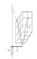
このような二酸化炭素の海洋隔離の研究は、室内実験と海洋実験とが補完し合いながら行なわれており、二酸化炭素の海中における希釈拡散の様子を予測するモデルの研究が重要視されている。しかし、予測モデルを検証するための海洋実験の方法は、いまだ手探りの状況にあって確立されていないのが現状である。そして、予測モデルを検証するために、海水中に溶解した二酸化炭素の濃度を測定する場合、水素指数(pH)の値を測定して行われる。また、拡散の様子を知るためには、海中空間を図8に示したようにメッシュまたはマトリックス状に切り分け、このメッシュまたはマトリックスに沿ってpH値を測定する必要がある。この測定は、複数の点を同時に行なうことが望まれる。
【0003】
ところで、海中空間における分布を測定する場合、次のような方法が考えられる。
(1)固定昇降ブイ法:この方法は、海底に多数の昇降するブイを設置し、ブイに取り付けた測定器によって測定する。しかし、この固定昇降ブイ法は、測定器を潮流の流れに沿って移動させることができないため、実用的でない。
(2)浮遊フロート法:浮力を調整した多数のフロートを海中に投下し、フロートに取り付けた測定器をフロートとともに潮流の流れに乗せて移動させる。この方法は、潮流の流れに沿った測定が可能であるが、位置制御ができないので成り行き任せとなり、望むような分布の測定を行なうことができない。
(3)ROV法:ケーブルで母船に接続した無人潜水機であるROV(Remotely Operated Vehicle)に計測器を搭載し、ROVを潜行させて測定を行なう。このROV法は、位置制御が可能であって所望の位置の計測を行なうことが可能である。しかし、ROVは、ケーブルに束縛されているために移動できる範囲が狭く、広い範囲の分布を測定することが困難である。
(4)AUV法:この方法は、無索の無人潜水機であるAUV(Autonomous Underwater Vehicle)に計測器を搭載して測定を行なう法法である。このAUV法は、位置制御か可能であるばかりでなく、無策であるところからケーブルに拘束されず、自由に海中を移動できるため、海中空間の分布を測定するには最適な方法であると考えられている。
【0004】
【発明が解決しようとする課題】
現在、AUVは、各方面で開発が進められており、実用の段階にある。そして、無人潜水機は、一般に機体を水平方向に進めるための水平推進器と、深度を調整するために機体を上下方向に移動させるための垂直推進器とを、機体の長手方向中央部に備えている。また、特開平8−169398号公報には、機体の周囲に3基の水平推進器を機体の前後方向に平行に配置するとともに、機体の左右両側のそれぞれに垂直推進器を設け、さらに機体の横方向に向けた推進器を機体の中央部に配置し、ピッチングやヨーイング、ローリングの制御を安定して行なうようにしたものが記載されている。しかし、このような無人潜水機は、多くの推進器を備えているために高価であって重量も増大する。しかも、3基の水平推進器が機体の長手方向に平行に配置してあるため、機体が長くなると旋回(回頭)に要するモーメントが充分に得られず、迅速な回頭制御などが困難となる。
【0005】
本発明は、前記従来技術の欠点を解消するためになされたもので、推進器の数を少なくして大きな回頭モーメントが得られるようにすることを目的としている。
また、本発明は、バラストのみによって機体を自動的に水平に保持できるようにすることを目的としている。
さらに、本発明は、迅速に潜水できるようにすることを目的としている。
そして、本発明は、水中空間の予め定めた複数の点をほぼ同時に計測できるようにすることを目的としている。
【0006】
【課題を解決するための手段】
上記の課題を解決するために、本発明に係る潜水機は、推進器を備えて水中を航行する潜水機において、前記推進器は機体の長手方向の一側に周方向に沿って3つ取り付けられ、かつその軸線が前記機体の軸線上の一点で会するように前記機体に取り付けてある。
【0007】
更に、前記機体の上部にトランスポンダ送受波器を設けるとともに、前記機体の長手方向他側に潜水用バラスト装着部と浮上用バラスト装着部を有して各々バラストを着脱自在としており、潜水用バラストを投棄して浮上用バラストを浮上用バラスト装着部に装着したときに、潜水機重心を長手方向中心部であって、浮心の下方に位置させてなる。
【0008】
そして、本発明に係る分布測定方法は、水中に存在するものまたは水温などの分布を測定する方法であって、推進器を備えて水中を航行する潜水機において、前記推進器は機体の長手方向の一側に周方向に沿って3つ取り付けられ、かつその軸線が前記機体の軸線上の一点で会するように前記機体に取り付けてあり、前記機体の上部にトランスポンダ送受波器を設けるとともに、前記機体の長手方向他側に潜水用バラスト装着部と浮上用バラスト装着部を有して各々バラストを着脱自在としており、潜水用バラストを投棄して浮上用バラストを浮上用バラスト装着部に装着したときに、潜水機重心を長手方向中心部であって、浮心の下方に位置させてなる潜水機に水中存在物または水温などを検出するセンサを搭載し、複数の前記潜水機を同時に潜行させて水中存在物または水温などを検出することを特徴としている。
【0009】
【作用】
上記のごとく構成した本発明に係る潜水機は、3つ以上の推進器が機体の軸線上の一点で会するように傾斜させて取り付けてあるため、各推進器は機体に対して、機体の軸線と平行な方向の成分の推力と、機体の軸線に対して直交した方向の成分の推力とを与える。したがって、すべての推進器の出力が同じである場合、それらの合力が機体に機体の軸線方向に進める推力を与える。また、いずれかの推進器を停止させると、機体に回頭させるモーメントを与える。しかも、推進器が機体に与える推力は、機体の軸線と直交した方向の成分を有しているため、容易、迅速な回頭制御をすることができる。
【0010】
そして、機体の長手方向一側に各推進器を配置し、機体の長手方向他側に設けた浮上用バラスト装着部に浮上用バラストを装着したときに、機体の重心が長手方向中心部であって浮心の下方に位置するようにしているため、潜水時に装着した潜水用バラストを投棄すると、機体が自動的に水平状態となり、機体を水平にする制御が不要であって、構造の簡素化、コストの低減を図ることができる。また、機体の長手方向他側、例えば機体の先端側に潜水用バラスト装着部を設けて潜水用バラストを装着できるようにしたため、潜水用バラストを機体に装着したときに、機体の重心位置が長手方向中心部より長手方向他側となり、潜水する場合に、機体の長手方向が上下方向となるため、迅速な潜水を行なうことができる。
【0011】
また、本発明に係る分布測定方法は、上記した潜水機に分布の測定の目的に合った測定器を搭載し、測定器を搭載した潜水機の複数を同時に潜行させて測定を行なうようにしているため、例えばpHの測定や、プランクトンの量の測定、濁度の測定、水温の測定などを、複数の点においてほぼ同時に行なうことができ、正確な分布の測定を行なうことができる。
【0012】
【発明の実施の形態】
本発明に係る潜水機および分布測定方法の好ましい実施の形態を、添付図面にしたがって詳細に説明する。
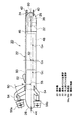
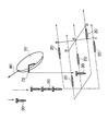
図1は本発明の実施の形態に係る潜水機の側面図であり、図2はその平面図である。なお、この実施形態においては、水中のpH値の測定用に特殊化した潜水機について説明するが、これに限定されないことはもちろんである。
【0013】
図1および図2において、潜水機20は、いわゆるAUVと称される無索の無人潜水機であって、機体22が円筒状に形成してある。機体22は、数千メートルの深海における水圧にも耐えられる圧力容器となっていて、前端(図1の右側端)と後端とに半球状のドーム部24、26が一体に設けてある。そして、機体22は、長手方向の他側となる前端部の内部(前端室)28が外部(水中)と連通している。この前端室28には、潜水用バラスト装着部30と浮上用バラスト装着部32とが設けてって、後述するように、潜水用バラスト装着部30に潜水用バラストを着脱自在に取り付けることができ、浮上用バラスト装着部32に浮上用バラストを着脱自在に装着することが可能となっている。
【0014】
潜水機20は、後述するように、潜水するときに機体22の先端側から潜水するようになっていて、先端側ドーム部24の先端中央部に、潜水用バラストを投棄するための開口(図示せず)が設けてある。また、潜水機20は、浮上用バラストを水平となった機体22の下方(図1の下方)に投棄できるようにしてあって、機体22の下部の、浮上用バラスト装着部32と対応した位置に図示しないバラスト投棄口が形成してある。
【0015】
さらに、前端室28には、水中(海水中)に溶け込んでいる二酸化炭素の濃度を測定するためのpHセンサ38が配設してある。そして、先端側ドーム24には、図示しない水の取入れ口と排出口とが設けてあって、前端室28の内部を水が自由に通流できるようになっていて、pHセンサ38によって水中の水素イオン濃度を検出することができるようにしてある。また、先端ドーム部24には、後述するように、潜水機20を母船に引き上げる際の吊上げフック40が設けてある。さらに、潜水機20は、水面に浮上した潜水機20を容易に見つけることができるように、ライトを点滅するフラッシャ42がドーム部24から突出して設けてある。一方、機体22の後端のドーム部26には、潜水機20を潜水させる際に吊り下げるための投下フック44が設けてある。
【0016】
潜水機20は、前端室28の後方側が外部と遮断される密閉室46となっていて、この密閉室46に動力源となる電池48が配置してある。また、電池48の後方側には、コンピュータや制御装置、送受信機、記録装置などの電子機器50が設置してある。さらに、機体22の外部の上部には、トランスポンダ送受波器52が設けてある。トランスポンダ送受波器52は、図1、図2に図示しない母船と交信するためのもので、母船が水中に放射した超音波信号を電気信号に変換して機体22内部の受信機に入力し、潜水機20の送信機が出力した電気信号を超音波信号に変換して水中に放射する。
【0017】
機体22の長手方向一側となる後端部の外周面には、ブラケット54を介して3つの推進器56(56a、56b、56c)が取り付けてある。これらの推進器56は、機体22の軸線58を中心とした同一円周上に配置してある。実施形態の場合、各推進器56は、方向(方位)制御や深度制御するための推進力の演算を容易にするため、潜水機20の軸線58に対して120度の等間隔で配置してある。そして、トランスポンダ送受波器52を上にしてした状態で潜水機20を後方から見た場合、実施形態の場合、推進器56aが時計の文字盤上で12時の位置にあり、推進器56bが4時の位置、推進器56cが8時の位置にある。
【0018】
また、各推進器56a〜56cは、後部側を内向きに傾斜させて取り付けてある。そして、各推進器56の機体22の軸線58に対する傾斜角θは、それぞれ同じにしてあって、各推進器56の軸心60が潜水機20の後方において、潜水機20の軸心58上の一点で会するようになっている。このため、各推進器56は、潜水機20に斜め前方に進む推力を与え、各推進器56の出力する推力が等しいと、その合力が潜水機20を前方に推進する。推進器56の傾斜角θは、機体22の軸線58に平行な方向の成分の推力と、軸線58に直交した方向の成分の推力が得られる角度であれば任意に設定することができる。しかし、傾斜角θがあまり大きいと前進のための推力が小さくなり、傾斜角θが小さすぎる回頭モーメントが小さくなって回頭能力が低下する。このため、傾斜角θは、望ましくは5〜50度、実施形態の場合10〜30度にしてある。
【0019】
なお、潜水機20に潜水用バラストと浮上用バラストとを搭載した場合、潜水機20の重心は、潜水機20の左右方向の中心である図2に示す軸心58上であって、図1にGA として示したように、上下方向の中心(軸線58)の下側であって、長手方向(前後方向)の中心より前方側となるようにしてある。また、潜水機20に浮上用バラストだけを搭載した場合、重心GB が図1に示したように、潜水機20の長手方向(前後方向)の中心部であって軸心58より下側に位置し、潜水機20の浮心62の下方に位置するようになっている。さらに、潜水機20は、潜水用バラストと浮上用バラストとのいずれも搭載していない場合、重心GC が軸心58の下側であって、潜水機20の長手方向の中心より後方側に位置するようにしてある。そして、いずれの場合も、重心の位置は、機体22の左右方向中心部にある。
【0020】
また、潜水機20は、深度センサ、方位センサ、速度計、記録装置など(いずれも図示せず)が搭載してあって、与えられた深度と方位とを維持して所定の速度で潜行できるようになっているとともに、測定したpH値を測定した深度、位置とともに記録装置に記録できるようにしてある。
【0021】
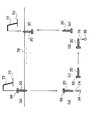
このように構成した実施形態に係る潜水機20は、潜水用バラスト装着部30に潜水用バラストを装着し、浮上用バラスト装着部32に浮上用バラストを装着すると、重心GA が潜水機20の前後方向中心より前方側に位置する。このため、潜水機20は、図3(a)に示したように、母船70に設けた投下・回収装置72に投下フック44を介して吊り下げ、着水させて切り離すと、同図(b)に示したように、先端を下に向けて自重で潜水(潜航)する。そして、潜水機20は、必要に応じて潜水(下降)しつつ水中のpH値の測定を行なう。潜水機20の深度は、図示しない深度センサによって検知され、トランスポンダ送受波器52によって超音波信号に変換されて水中に放射される。母船70は、潜水機20からの超音波信号を受信して潜水機20の位置を監視する。
【0022】
潜水機20は、所定の深度に達すると搭載してある制御装置が、母船70からの超音波信号による指令により、または予め与えられているプログラムに従って潜水用バラスト装着部30を作動し、図3(b)に示したように、潜水用バラスト34を潜水機20の先端から矢印74のように投下する。これにより、潜水機20は、重心の位置が長手方向(前後方向)の中心部であって、浮心62の下方のGB となる。このため、潜水機20は、同図(c)に示したように、自動的に水平となる。そこで、各推進器56a〜56cを、推力が同じとなるように駆動することにより、潜水機20は水平に潜行する。
【0023】
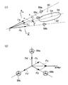
すなわち、図4(1)に示したように、各推進器56a〜56cが機体22に与える推力のベクトルをFa、Fb、Fcとし、各推力の機体22の軸線58と直交した方向の成分のベクトルをFa′Fb′Fc′とすると、
【数1】
【0024】
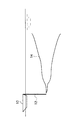
一方、機首を左右上下に振る場合、各推進器56a〜56cの推力Fa、Fb、Fcの大きさを変え、軸線58と直交した方向の成分Fa′、Fb′、Fc′のバランスを崩し、その合力によって回頭させる。例えば、潜水機20を左回頭させる場合、破線に示したベクトルFx を発生させればよい。すなわち、この場合、推進器56bを前進力Fbが得られるように正方向に回転させてFb′を発生させるとともに、推進器56cを後進力−Fcが得られるように逆回転させて−Fc′を発生させる。また、推進器56aは駆動を停止する。これにより、水平軸Yに平行な合成ベクトルFxが発生する。この力Fxの作用点は、機体22の重心GB の後方に位置するため、機首を左に回頭するモーメントを発生し、機首が左に回頭する。他の方向への回頭も同様に行なうことができる。
【0025】
そして、潜水機20は、実施形態の場合、潜行中の重心位置が浮心62の下方のGB にあるため、常にトランスポンダ送受波器52側を上にした状態が保持される。さらに、実施形態においては、各推進器56は、潜水機20の軸線58に対して傾斜しているため、軸線58と直交した方向の成分の推力を機体22に与えており、潜水機20の回頭を容易、迅速に行なうことができる。また、各推進器56は、機体22の後端部に設けてあり、図2に示したように、回頭中心となる重心位置をGB と、各推進器56の推力の作用点との距離Lが大きくしてあり、重心GB から各推進器56の軸線60に下す垂線の長さを長くでき、大きな回頭モーメントが得られてより迅速な回頭制御を行なうことができる。
【0026】
このようにして、潜水機20は、搭載された図示しない制御装置が深度センサ、方位センサ、速度センサなどの検出信号に基づいて、予め与えられたプログラムに従って所定の深度、方位に維持されて潜行し、pH値の測定を行なう。潜水機20は、所定時間の深度保持、方位保持潜行計測が終了すると、制御装置が母船70からの指令により、または予め与えられているプログラムに従って推進器56の駆動を停止し、浮上用バラスト装着部32を操作し、図3(d)に矢印76に示したように、浮上用バラスト36を機体22の下方から投棄する。これにより、潜水機20は、軽くなるとともに、重心の位置が図1に示したように、前後方向の中心より後端側のGC に移る。このため、潜水機20は、同図(e)に示したように、自動的に先端が上を向き、浮上を開始して浮上計測を行なう。
【0027】
潜水機20は、さらに浮上すると、同図(f)に示したように、先端が水面78の上に露出する。この際、フラッシャ42が光を点滅させるため、母船70の乗組員は、浮上した潜水機20の位置を目視により容易に確認することができる。そして、潜水機20は、投下・回収装置72によって吊上げフック40を介して吊り上げられ、母船70に回収される。なお、潜水機20は、浮上用バラスト36を投棄して浮上したときに、トランスポンダ送受波器52が水中に没して母船70と交信できる状態が維持されるように設計されている。
【0028】
このように実施の形態においては、各推進器56を傾斜させて機体22に取り付けているため、各推進器56は、機体22の軸線58に沿った方向の成分と、軸線58に直交した方向の成分とを有する推力を機体22に与えるため、各推進器56の出力を調整することにより、潜水機20の回頭操作を容易、迅速に行なうことができる。また、実施形態に係る潜水機20は、潜水用バラスト34と浮上用バラスト36とを搭載した場合、重心位置が前後方向の中心より前にあり、潜水するときに先端を下方にして潜水するため、迅速な潜水が可能であって、所定の深度まで潜水する時間を短くすることができる。そして、潜水機20は、潜水用バラスト34を投棄すると、重心が機体22の前後方向の中心部であって、浮心の下方に位置するようになるため、機体22が水中で自動的に水平となり、複雑な制御が必要でなく、構造の簡素化が図れてコストを低減することができる。
【0029】
なお、前記実施形態においては、推進器56が3つである場合について説明したが、4つ以上であってもよい。また、前記実施の形態においては、各推進器56が後部側を内向きとなるように傾斜させた場合について説明したが、推進器56の後部側を外向きとなるように傾斜させてもよい。そして、前記実施の形態においては、pHセンサ38によって水中のpH値を検出する場合について説明したが、センサの種類を変えたり複数のセンサを搭載することにより、水温やプランクトンの量、水の濁度、溶存酸素量などの測定に適用してもよい。さらに、例えば先端側のドーム部24を透明なプラスチックなどによって形成し、内部にテレビカメラを設置してもよい。
【0030】
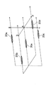
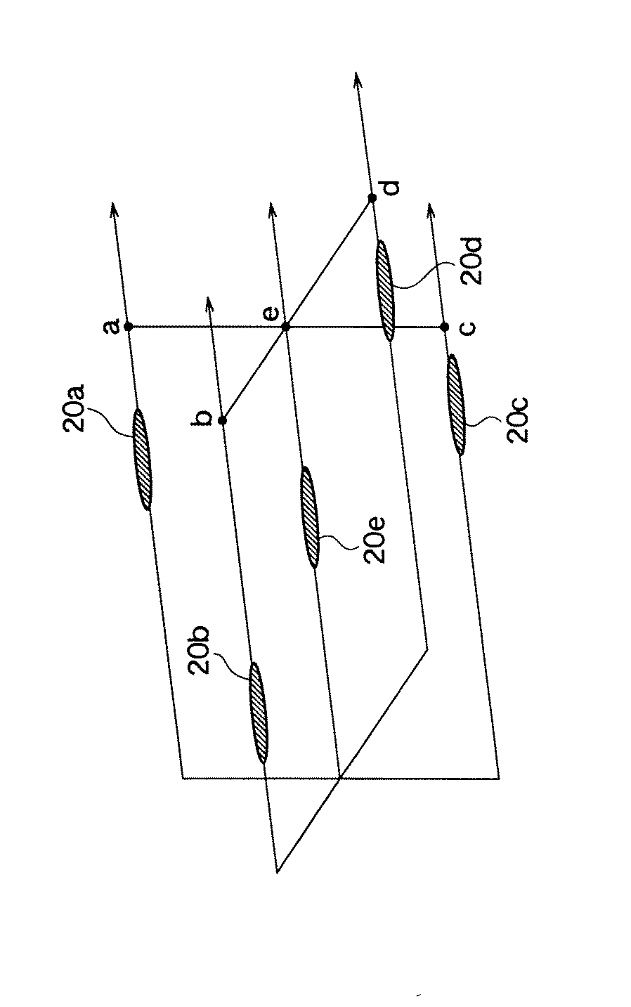
ところで、前記したように二酸化炭素を海中に注入した場合、二酸化炭素は、潮流座標系に乗った水塊の中を拡散して行く。このため、二酸化炭素の海洋隔離においては、潮流座標系の中の相対位置によって拡散が論じられる。したがって、二酸化炭素の拡散状態を測定する場合、測定点の絶対的位置を知ることはあまり重要でなく、大切なことは、潮流座標系における相対位置と測定の同時性である。すなわち、時間合わせによる多点観測が必要となる。そこで、二酸化炭素の拡散状態を検出するために、上記の潜水機20によってpH値を測定する場合、図5に示したように、例えば水塊内の点a、b、c、d、eを含む断面を5台の潜水機20a〜20eのそれぞれが、許容される時間の範囲(誤差)Δt内に通過させる必要がある。
【0031】
図6は、実際の二酸化炭素の拡散状態を測定する方法を具体的に示したもので、母船70を矢印80のように水塊内の点a、b、c、d、eを含む断面と平行に航行させ、潜水機20を母船70から所定の位置に順次投下する。各潜水機20は、制御装置が予め与えられているプログラムに従って、所定の方位を向くように推進器56を制御し、予定のコースをpH値を測定しつつ潜行する。この場合、深く潜水させる潜水機20に対しては、より浅い位置を潜行させる潜水機20より重い潜水用バラスト34を搭載し、潜航速度を大きくするとよい。もちろん、すべての潜水機20の潜水用バラスト34を同じにしてもよい。なお、各潜水機20のトランスポンダ送受波器52は、送受波の周波数が相互に異ならせ、混信などが生じないようにする。また、二酸化炭素の拡散状態を調査する場合、前記したように絶対位置は重要でなく、潮流座標系内の相対位置を把握できればよいため、速度計とし、安価な1軸対水速度計、超音波ソナーなどを使用することができる。
【0032】
【発明の効果】
以上に説明したように、本発明によれば、3つ以上の推進器が機体の軸線上の一点で会するように傾斜させて取り付けてあるため、各推進器は機体に対して、機体の軸線と平行な方向の成分の推力と、機体の軸線に対して直交した方向の成分の推力とを与えるため、容易、迅速な回頭制御をすることができる。
【0033】
そして、機体の長手方向一側に各推進器を配置し、機体の長手方向他側に設けた浮上用バラスト装着部に浮上用バラストを装着したときに、機体の重心が長手方向中心部であって浮心の下方に位置するようにしているため、潜水時に装着した潜水用バラストを投棄すると、機体が自動的に水平状態となり、機体を水平にする制御が不要であって、構造の簡素化、コストの低減を図ることができる。また、機体の長手方向他側、例えば機体の先端側に潜水用バラスト装着部を設けて潜水用バラストを装着できるようにしたことにより、潜水用バラストを機体に装着したときに、機体の重心位置が長手方向中心部より長手方向他側となり、潜水する場合に、機体の長手方向が上下方向となるため、迅速な潜水を行なうことができる。
【0034】
また、本発明に係る分布測定方法は、上記した潜水機に分布の測定の目的に合った測定器を搭載し、測定器を搭載した潜水機の複数を同時に潜行させて測定を行なうようにしているため、例えばpHの測定や、プランクトンの量の測定、濁度の測定、水温の測定などを、複数の点においてほぼ同時に行なうことができ、正確な分布の測定を行なうことができる。
【図面の簡単な説明】
【図1】本発明の実施の形態に係る潜水機の側面図である。
【図2】本発明の実施の形態に係る潜水機の平面図である。
【図3】実施の形態に係る潜水機の作用を説明する図である。
【図4】実施の形態に係る潜水機の回頭操作を説明する図である。
【図5】AUVによってpH値の分布を測定する概念図である。
【図6】実施の形態に係る潜水機によるpH値の分布を測定する方法を説明する図である。
【図7】二酸化炭素の海中隔離の方法を説明する図である。
【図8】海中隔離した二酸化炭素の拡散の様子を測定する方法の説明図である。
【符号の説明】
20………潜水機、22………機体、30………潜水用バラスト装着部、
32………浮上用バラスト装着部、56a〜56c………推進器、
58………機体の軸線、60………推進器の軸線、62………浮心、
GA 、GB 、GC ………重心。[0001]
BACKGROUND OF THE INVENTION
The present invention relates to a submarine that navigates underwater, and more particularly to a submarine that navigates underwater unmannedly equipped with three or more propulsion devices.
[0002]
[Prior art]
In recent years, with the development of industry and convenience of living, carbon dioxide (CO2) Will increase, and there is a strong concern that it will affect the global warming phenomenon. For this reason, research is being conducted worldwide to sequester carbon dioxide emitted from factories and power plants in the ocean. That is, as shown in FIG. 7, the liquefied carbon dioxide is transported to a predetermined sea area by the
Such research on the sequestration of carbon dioxide in the ocean has been carried out while complementing laboratory experiments and ocean experiments, and research on models that predict the state of dilution and diffusion of carbon dioxide in the sea is regarded as important. However, the current state of the ocean experiment method for verifying the prediction model has not been established because it is still in a frustrating situation. And in order to verify a prediction model, when measuring the density | concentration of the carbon dioxide melt | dissolved in seawater, the value of a hydrogen index (pH) is measured and performed. In order to know the state of diffusion, it is necessary to cut the underwater space into a mesh or matrix as shown in FIG. 8 and measure the pH value along this mesh or matrix. It is desirable to perform this measurement at a plurality of points simultaneously.
[0003]
By the way, when measuring the distribution in the underwater space, the following methods can be considered.
(1) Fixed elevating buoy method: In this method, a number of elevating buoys are installed on the seabed, and measurement is performed by a measuring instrument attached to the buoy. However, this fixed lift buoy method is not practical because the measuring instrument cannot be moved along the tidal current.
(2) Floating float method: A large number of floats with adjusted buoyancy are dropped into the sea, and the measuring instrument attached to the float is moved along with the float on the tidal current. Although this method can measure along the flow of the tidal current, it cannot be controlled because the position cannot be controlled, and the desired distribution cannot be measured.
(3) ROV method: A measurement device is mounted on a ROV (Remotely Operated Vehicle), which is an unmanned submersible connected to the mother ship with a cable, and the ROV is submerged for measurement. This ROV method can control the position and can measure a desired position. However, since the ROV is constrained by the cable, the movable range is narrow, and it is difficult to measure a wide range of distribution.
(4) AUV method: This method is a method in which a measurement is mounted on an AUV (Autonomous Underwater Vehicle) that is an unmanned unmanned submersible. This AUV method is not only capable of position control, but also is not constrained by cables from where it is impossible, so it can move freely in the sea, so it is considered to be an optimal method for measuring the distribution of underwater space. It has been.
[0004]
[Problems to be solved by the invention]
Currently, AUV is being developed in various directions and is in a practical stage. The unmanned submersible is generally provided with a horizontal thruster for advancing the aircraft in the horizontal direction and a vertical thruster for moving the aircraft up and down to adjust the depth in the center in the longitudinal direction of the aircraft. ing. Japanese Patent Laid-Open No. 8-169398 discloses that three horizontal thrusters are arranged around the aircraft in parallel to the longitudinal direction of the aircraft, and vertical thrusters are provided on both the left and right sides of the aircraft. A propulsion device oriented in the lateral direction is arranged in the center of the airframe to control pitching, yawing and rolling stably. However, such an unmanned submersible is expensive and increases in weight because it includes many propulsion devices. Moreover, since the three horizontal thrusters are arranged in parallel to the longitudinal direction of the airframe, when the airframe becomes long, a moment required for turning (turning) cannot be sufficiently obtained, and quick turning control becomes difficult.
[0005]
The present invention has been made in order to eliminate the drawbacks of the prior art described above, and aims to reduce the number of propulsion devices so that a large turning moment can be obtained.
Another object of the present invention is to enable the airframe to be automatically held horizontally only by ballast.
Furthermore, an object of the present invention is to enable diving quickly.
An object of the present invention is to enable measurement of a plurality of predetermined points in the underwater space almost simultaneously.
[0006]
[Means for Solving the Problems]
In order to solve the above problems, a diving machine according to the present invention is:PropellerIn a submarine that sails underwater withThree of the propellers are attached to one side in the longitudinal direction of the airframe along the circumferential direction, and are attached to the airframe so that the axis meets at one point on the axis of the airframe.
[0007]
Further, a transponder transmitter / receiver is provided in the upper part of the airframe, and a diving ballast mounting portion and a floating ballast mounting portion are provided on the other side in the longitudinal direction of the airframe, and each ballast is detachable. When the ballast for levitation is discarded and the levitation ballast is mounted on the levitation ballast mounting portion, the center of gravity of the diving machine is located at the center in the longitudinal direction and below the buoyancy.
[0008]
And the distribution measuring method according to the present invention is:A method of measuring a distribution of what is present in water or a water temperature, etc., wherein the propulsion device is provided with a propulsion device, and three propulsion devices are provided along one side in the longitudinal direction along the circumferential direction. It is attached to the airframe so that its axis meets at one point on the axis of the airframe, a transponder transducer is provided on the upper side of the airframe, and a diving ballast on the other side in the longitudinal direction of the airframe There is a mounting part and a floating ballast mounting part, and each ballast is detachable, and when the diving ballast is discarded and the floating ballast is mounted on the floating ballast mounting part, the center of gravity of the diving machine is centered in the longitudinal direction. However, the submersible is located below the buoyancyIs equipped with a sensor for detecting an underwater entity or a water temperature, and the plurality of divers are simultaneously submerged to detect an underwater entity or a water temperature.
[0009]
[Action]
Since the submersible according to the present invention configured as described above is mounted with an inclination so that three or more propulsion devices meet at one point on the axis of the airframe, each propulsion device is attached to the airframe. A thrust of a component in a direction parallel to the axis and a thrust of a component in a direction orthogonal to the axis of the aircraft are given. Therefore, when the outputs of all the propellers are the same, their resultant force gives the aircraft a thrust to advance in the axial direction of the aircraft. Also, when any propulsion device is stopped, a moment to turn the aircraft is given. Moreover, since the thrust force applied to the aircraft by the propulsion device has a component in a direction perpendicular to the axis of the aircraft, it is possible to easily and quickly perform the turning control.
[0010]
When each propulsion unit is arranged on one side in the longitudinal direction of the fuselage and the flying ballast is mounted on the flying ballast mounting part provided on the other longitudinal side of the aircraft, the center of gravity of the fuselage is the longitudinal center. Because it is positioned below the buoyancy, if the diving ballast installed during diving is discarded, the aircraft will automatically be leveled, and control for leveling the aircraft is unnecessary, simplifying the structure Cost can be reduced. In addition, since the diving ballast is installed on the other side in the longitudinal direction of the fuselage, for example, on the tip side of the fuselage so that the diving ballast can be fitted, the center of gravity position of the fuselage is long when the diving ballast is fitted to the fuselage. In the case of diving on the other side in the longitudinal direction from the central portion in the direction, since the longitudinal direction of the machine body is the vertical direction, rapid diving can be performed.
[0011]
In addition, the distribution measurement method according to the present invention is configured such that the above-described diving machine is equipped with a measuring device suitable for the purpose of distribution distribution, and a plurality of diving machines equipped with the measuring device are simultaneously submerged for measurement. Therefore, for example, pH measurement, plankton amount measurement, turbidity measurement, water temperature measurement and the like can be performed almost simultaneously at a plurality of points, and an accurate distribution can be measured.
[0012]
DETAILED DESCRIPTION OF THE INVENTION
Preferred embodiments of a diving machine and a distribution measuring method according to the present invention will be described in detail with reference to the accompanying drawings.
FIG. 1 is a side view of a diving machine according to an embodiment of the present invention, and FIG. 2 is a plan view thereof. In addition, in this embodiment, although the diving machine specialized for the measurement of pH value in water is demonstrated, of course, it is not limited to this.
[0013]
1 and 2, the diving
[0014]
As will be described later, the diving
[0015]
Further, the
[0016]
In the submersible 20, the rear side of the
[0017]
Three propulsion devices 56 (56a, 56b, 56c) are attached to the outer peripheral surface of the rear end portion on one side in the longitudinal direction of the
[0018]
Moreover, each
[0019]
When the diving ballast and the floating ballast are mounted on the
[0020]
Further, the diving
[0021]
In the
[0022]
When the
[0023]
That is, as shown in FIG. 4 (1), the thrust vector that each
[Expression 1]
[0024]
On the other hand, when the nose is swung left and right and up and down, the magnitudes of the thrusts Fa, Fb and Fc of the
[0025]
And, in the case of the embodiment, the submersible 20 has a position of the center of gravity during the dive below the buoyancy 62.BTherefore, the state where the transponder transmitter /
[0026]
In this way, the submersible 20 is submerged by a mounted control device (not shown) based on detection signals from the depth sensor, the azimuth sensor, the speed sensor, and the like and maintained at a predetermined depth and azimuth according to a predetermined program. Then, the pH value is measured. When the submersible 20 completes the depth dive and azimuth dive measurement for a predetermined time, the control device stops the driving of the
[0027]
When the
[0028]
Thus, in the embodiment, since each
[0029]
In addition, in the said embodiment, although the case where the number of the
[0030]
By the way, when carbon dioxide is injected into the sea as described above, the carbon dioxide diffuses in the water mass on the tidal current coordinate system. For this reason, in ocean sequestration of carbon dioxide, diffusion is discussed by relative position in the tidal coordinate system. Therefore, when measuring the diffusion state of carbon dioxide, it is not very important to know the absolute position of the measurement point, and what is important is the relative position in the tidal current coordinate system and the simultaneity of the measurement. In other words, multipoint observation by time adjustment is required. Therefore, when the pH value is measured by the
[0031]
FIG. 6 specifically shows a method of measuring the actual diffusion state of carbon dioxide, and shows a cross section including points a, b, c, d, and e in the water body as indicated by an
[0032]
【The invention's effect】
As described above, according to the present invention, since three or more propulsion devices are attached so as to meet at one point on the axis of the airframe, each propulsion device is attached to the airframe. Since the thrust of the component in the direction parallel to the axis and the thrust of the component in the direction orthogonal to the axis of the aircraft are given, easy and quick turn control can be performed.
[0033]
When each propulsion unit is arranged on one side in the longitudinal direction of the fuselage and the flying ballast is mounted on the flying ballast mounting part provided on the other longitudinal side of the aircraft, the center of gravity of the fuselage is the longitudinal center. Because it is positioned below the buoyancy, if the diving ballast installed during diving is discarded, the aircraft will automatically be leveled, and control for leveling the aircraft is unnecessary, simplifying the structure Cost can be reduced. In addition, by providing a diving ballast mounting part on the other side in the longitudinal direction of the aircraft, for example, on the tip side of the aircraft, so that the diving ballast can be mounted, the position of the center of gravity of the aircraft when the diving ballast is mounted on the aircraft Becomes the other side in the longitudinal direction from the central portion in the longitudinal direction, and when diving, since the longitudinal direction of the machine body is the vertical direction, rapid diving can be performed.
[0034]
In addition, the distribution measurement method according to the present invention is configured such that the above-described diving machine is equipped with a measuring device suitable for the purpose of distribution distribution, and a plurality of diving machines equipped with the measuring device are simultaneously submerged for measurement. Therefore, for example, pH measurement, plankton amount measurement, turbidity measurement, water temperature measurement and the like can be performed almost simultaneously at a plurality of points, and an accurate distribution can be measured.
[Brief description of the drawings]
FIG. 1 is a side view of a diving machine according to an embodiment of the present invention.
FIG. 2 is a plan view of the diving machine according to the embodiment of the present invention.
FIG. 3 is a diagram for explaining the operation of the diving machine according to the embodiment.
FIG. 4 is a diagram for explaining a turning operation of the diving machine according to the embodiment.
FIG. 5 is a conceptual diagram for measuring the distribution of pH values by AUV.
FIG. 6 is a diagram for explaining a method of measuring the distribution of pH values by the diving machine according to the embodiment.
FIG. 7 is a diagram for explaining a method of sequestering carbon dioxide in the sea.
FIG. 8 is an explanatory diagram of a method for measuring the state of diffusion of carbon dioxide isolated in the sea.
[Explanation of symbols]
20 ......... Submersible, 22 ......... Aircraft, 30 ......... Dive ballast mounting part,
32 ..... Ballast mounting part for levitation, 56a to 56c .....
58 ……… the axis of the fuselage, 60 ……… the axis of the propeller, 62 ……… the buoyancy,
GA, GB, GC……… The center of gravity.
Claims (2)
前記推進器は機体の長手方向の一側に周方向に沿って3つ取り付けられ、かつその軸線が前記機体の軸線上の一点で会するように前記機体に取り付けてあり、前記機体の上部にトランスポンダ送受波器を設けるとともに、前記機体の長手方向他側に潜水用バラスト装着部と浮上用バラスト装着部を有して各々バラストを着脱自在としており、潜水用バラストを投棄して浮上用バラストを浮上用バラスト装着部に装着したときに、潜水機重心を長手方向中心部であって、浮心の下方に位置させてなることを特徴とする潜水機。 In a submersible that has a propeller and sails underwater,
Three of the propellers are attached along the circumferential direction on one side in the longitudinal direction of the airframe, and are attached to the airframe so that the axis meets at one point on the axis of the airframe. A transponder transmitter / receiver is provided, and a diving ballast mounting portion and a floating ballast mounting portion are provided on the other side in the longitudinal direction of the machine body, and each ballast is detachable. A diving machine characterized in that when mounted on a floating ballast mounting section, the center of gravity of the diving machine is located in the center in the longitudinal direction and below the floating core .
Priority Applications (1)
| Application Number | Priority Date | Filing Date | Title |
|---|---|---|---|
| JP2000349261A JP4417543B2 (en) | 2000-11-16 | 2000-11-16 | Submersible and distribution measuring method |
Applications Claiming Priority (1)
| Application Number | Priority Date | Filing Date | Title |
|---|---|---|---|
| JP2000349261A JP4417543B2 (en) | 2000-11-16 | 2000-11-16 | Submersible and distribution measuring method |
Publications (2)
| Publication Number | Publication Date |
|---|---|
| JP2002145187A JP2002145187A (en) | 2002-05-22 |
| JP4417543B2 true JP4417543B2 (en) | 2010-02-17 |
Family
ID=18822699
Family Applications (1)
| Application Number | Title | Priority Date | Filing Date |
|---|---|---|---|
| JP2000349261A Expired - Fee Related JP4417543B2 (en) | 2000-11-16 | 2000-11-16 | Submersible and distribution measuring method |
Country Status (1)
| Country | Link |
|---|---|
| JP (1) | JP4417543B2 (en) |
Cited By (1)
| Publication number | Priority date | Publication date | Assignee | Title |
|---|---|---|---|---|
| KR20210067115A (en) | 2019-11-29 | 2021-06-08 | 국방과학연구소 | Small Underwater Vehicle having a hovering system using the tube type launcher and Method for assembling the same |
Families Citing this family (12)
| Publication number | Priority date | Publication date | Assignee | Title |
|---|---|---|---|---|
| JP4568837B2 (en) * | 2004-08-26 | 2010-10-27 | 国立大学法人東北大学 | Liquid carbon dioxide transport system and liquid carbon dioxide diffusion method |
| JP5481986B2 (en) * | 2009-07-17 | 2014-04-23 | 株式会社Ihi | Tank level measuring device |
| KR101115211B1 (en) * | 2009-07-24 | 2012-04-05 | 대우조선해양 주식회사 | An Unmanned Underwater Vehicle with Folding Stabilizer Fins and a Vector Propeller |
| US20120090385A1 (en) * | 2010-10-15 | 2012-04-19 | Utmost Tech Llc | System for monitoring underwater characteristics |
| RU2532669C1 (en) * | 2013-09-03 | 2014-11-10 | Лев Петрович Петренко | Method for improvement of submarine mobility (russian logic version - version 5) |
| JP6501341B2 (en) * | 2014-08-25 | 2019-04-17 | 学校法人金沢工業大学 | Search device |
| CN108216537A (en) * | 2016-12-13 | 2018-06-29 | 上海海洋大学 | One kind is used for the manual load rejection mechanism of manned underwater vehicle |
| JP7006900B2 (en) * | 2017-03-31 | 2022-01-24 | 国立研究開発法人 海上・港湾・航空技術研究所 | Input / collection system for multiple underwater vehicles |
| CN110475712B (en) * | 2017-03-31 | 2022-06-24 | 国立研究开发法人海上·港湾·航空技术研究所 | Control method, input method, recovery method, control system and input recovery equipment of control system of underwater vehicle |
| JP6991545B2 (en) * | 2017-03-31 | 2022-01-12 | 国立研究開発法人 海上・港湾・航空技術研究所 | Operation method of multiple underwater vehicles and operation system of multiple underwater vehicles |
| JP7248343B2 (en) * | 2017-03-31 | 2023-03-29 | 国立研究開発法人 海上・港湾・航空技術研究所 | A method of inserting a plurality of underwater vehicles and a method of lifting and recovering them |
| JP7195582B2 (en) * | 2018-10-03 | 2022-12-26 | 国立研究開発法人 海上・港湾・航空技術研究所 | Method for lifting and recovering a plurality of underwater vehicles, and system for lifting and recovering a plurality of underwater vehicles |
-
2000
- 2000-11-16 JP JP2000349261A patent/JP4417543B2/en not_active Expired - Fee Related
Cited By (2)
| Publication number | Priority date | Publication date | Assignee | Title |
|---|---|---|---|---|
| KR20210067115A (en) | 2019-11-29 | 2021-06-08 | 국방과학연구소 | Small Underwater Vehicle having a hovering system using the tube type launcher and Method for assembling the same |
| US11597484B2 (en) | 2019-11-29 | 2023-03-07 | Agency For Defense Development | Small underwater vehicle having a hovering system using the tube type launcher and method for assembling the same |
Also Published As
| Publication number | Publication date |
|---|---|
| JP2002145187A (en) | 2002-05-22 |
Similar Documents
| Publication | Publication Date | Title |
|---|---|---|
| CN106043632B (en) | A kind of application method of deep-sea unmanned submariner device | |
| US20190256181A1 (en) | Seismic autonomous underwater vehicle | |
| CN209938902U (en) | Sound/light/magnetism comprehensive detection type unmanned underwater vehicle | |
| JP4417543B2 (en) | Submersible and distribution measuring method | |
| KR100478811B1 (en) | Autonomous underwater vehicle and operational method | |
| US10604218B2 (en) | Manoeuvring device and method therof | |
| JP2007276609A (en) | Underwater glider | |
| CN104527952B (en) | Minitype autonomous underwater vehicle | |
| JP2007276609A5 (en) | ||
| KR20150140172A (en) | Dron flight and sea floor scanning exploration system using the same | |
| CN112937808B (en) | Deep sea in-situ manned experimental research platform | |
| CN114604400B (en) | Underwater glider with sinking detection function | |
| Yoshida et al. | An autonomous underwater vehicle with a canard rudder for underwater minerals exploration | |
| RU2563074C1 (en) | Underwater robotic complex | |
| CN205916310U (en) | Unmanned submerge ware in deep sea | |
| US4777819A (en) | Untethered oceanographic sensor platform | |
| JP5343448B2 (en) | Underwater vehicle and its submersible and horizontal navigation methods | |
| Yoshida et al. | Development of the cruising-AUV “Jinbei” | |
| JPH0457559B2 (en) | ||
| Yu et al. | Complete coverage tracking and inspection for sloping dam wall by remotely operated vehicles | |
| Ura et al. | Dives of AUV" r2D4" to rift valley of central Indian mid-ocean ridge system | |
| GB2361458A (en) | Semi-submersible marine craft | |
| JP2017001482A (en) | Unmanned underwater vehicle carrier device | |
| CN219475828U (en) | Submarine pipeline internal inspection system | |
| RU193453U1 (en) | CREWLESS SAILING TRIMARAN |
Legal Events
| Date | Code | Title | Description |
|---|---|---|---|
| A621 | Written request for application examination |
Free format text: JAPANESE INTERMEDIATE CODE: A621 Effective date: 20070328 |
|
| A131 | Notification of reasons for refusal |
Free format text: JAPANESE INTERMEDIATE CODE: A131 Effective date: 20090825 |
|
| A521 | Written amendment |
Free format text: JAPANESE INTERMEDIATE CODE: A523 Effective date: 20091020 |
|
| TRDD | Decision of grant or rejection written | ||
| A01 | Written decision to grant a patent or to grant a registration (utility model) |
Free format text: JAPANESE INTERMEDIATE CODE: A01 Effective date: 20091120 |
|
| A01 | Written decision to grant a patent or to grant a registration (utility model) |
Free format text: JAPANESE INTERMEDIATE CODE: A01 |
|
| A61 | First payment of annual fees (during grant procedure) |
Free format text: JAPANESE INTERMEDIATE CODE: A61 Effective date: 20091126 |
|
| R150 | Certificate of patent or registration of utility model |
Free format text: JAPANESE INTERMEDIATE CODE: R150 Ref document number: 4417543 Country of ref document: JP Free format text: JAPANESE INTERMEDIATE CODE: R150 |
|
| FPAY | Renewal fee payment (event date is renewal date of database) |
Free format text: PAYMENT UNTIL: 20121204 Year of fee payment: 3 |
|
| FPAY | Renewal fee payment (event date is renewal date of database) |
Free format text: PAYMENT UNTIL: 20131204 Year of fee payment: 4 |
|
| FPAY | Renewal fee payment (event date is renewal date of database) |
Free format text: PAYMENT UNTIL: 20141204 Year of fee payment: 5 |
|
| S111 | Request for change of ownership or part of ownership |
Free format text: JAPANESE INTERMEDIATE CODE: R313111 |
|
| S533 | Written request for registration of change of name |
Free format text: JAPANESE INTERMEDIATE CODE: R313533 |
|
| R350 | Written notification of registration of transfer |
Free format text: JAPANESE INTERMEDIATE CODE: R350 |
|
| LAPS | Cancellation because of no payment of annual fees |