JP4416285B2 - Patch image creation method and apparatus - Google Patents
Patch image creation method and apparatus Download PDFInfo
- Publication number
- JP4416285B2 JP4416285B2 JP2000211210A JP2000211210A JP4416285B2 JP 4416285 B2 JP4416285 B2 JP 4416285B2 JP 2000211210 A JP2000211210 A JP 2000211210A JP 2000211210 A JP2000211210 A JP 2000211210A JP 4416285 B2 JP4416285 B2 JP 4416285B2
- Authority
- JP
- Japan
- Prior art keywords
- patch
- area
- arrangement
- color
- image
- Prior art date
- Legal status (The legal status is an assumption and is not a legal conclusion. Google has not performed a legal analysis and makes no representation as to the accuracy of the status listed.)
- Expired - Fee Related
Links
- 238000000034 method Methods 0.000 title claims description 57
- 230000008569 process Effects 0.000 claims description 33
- 239000003086 colorant Substances 0.000 claims description 19
- 238000012545 processing Methods 0.000 claims description 12
- 238000004364 calculation method Methods 0.000 claims description 10
- 238000010586 diagram Methods 0.000 description 25
- 238000004422 calculation algorithm Methods 0.000 description 21
- 230000006870 function Effects 0.000 description 15
- 230000010365 information processing Effects 0.000 description 9
- 238000005259 measurement Methods 0.000 description 9
- 238000005314 correlation function Methods 0.000 description 8
- 230000008707 rearrangement Effects 0.000 description 8
- 238000004737 colorimetric analysis Methods 0.000 description 5
- 238000010606 normalization Methods 0.000 description 4
- 230000000694 effects Effects 0.000 description 3
- 238000012360 testing method Methods 0.000 description 3
- 238000012935 Averaging Methods 0.000 description 2
- 238000005311 autocorrelation function Methods 0.000 description 2
- 230000015572 biosynthetic process Effects 0.000 description 2
- 238000012937 correction Methods 0.000 description 2
- 238000002474 experimental method Methods 0.000 description 2
- 238000012986 modification Methods 0.000 description 2
- 230000004048 modification Effects 0.000 description 2
- 238000012546 transfer Methods 0.000 description 2
- 239000000470 constituent Substances 0.000 description 1
- 238000009795 derivation Methods 0.000 description 1
- 230000003287 optical effect Effects 0.000 description 1
Images


Classifications
-
- G—PHYSICS
- G06—COMPUTING; CALCULATING OR COUNTING
- G06T—IMAGE DATA PROCESSING OR GENERATION, IN GENERAL
- G06T5/00—Image enhancement or restoration
- G06T5/70—Denoising; Smoothing
-
- H—ELECTRICITY
- H04—ELECTRIC COMMUNICATION TECHNIQUE
- H04N—PICTORIAL COMMUNICATION, e.g. TELEVISION
- H04N1/00—Scanning, transmission or reproduction of documents or the like, e.g. facsimile transmission; Details thereof
- H04N1/46—Colour picture communication systems
- H04N1/56—Processing of colour picture signals
- H04N1/60—Colour correction or control
- H04N1/603—Colour correction or control controlled by characteristics of the picture signal generator or the picture reproducer
- H04N1/6033—Colour correction or control controlled by characteristics of the picture signal generator or the picture reproducer using test pattern analysis
-
- G—PHYSICS
- G06—COMPUTING; CALCULATING OR COUNTING
- G06T—IMAGE DATA PROCESSING OR GENERATION, IN GENERAL
- G06T2207/00—Indexing scheme for image analysis or image enhancement
- G06T2207/10—Image acquisition modality
- G06T2207/10024—Color image
Landscapes
- Engineering & Computer Science (AREA)
- Multimedia (AREA)
- Signal Processing (AREA)
- Physics & Mathematics (AREA)
- General Physics & Mathematics (AREA)
- Theoretical Computer Science (AREA)
- Facsimile Image Signal Circuits (AREA)
- Color Image Communication Systems (AREA)
- Accessory Devices And Overall Control Thereof (AREA)
- Image Processing (AREA)
Description
【0001】
【発明の属する技術分野】
本発明は、パッチ画像を作成するものに関する。
【0002】
【従来の技術】
近年コンピュータのカラー表現力の向上やカラープリンタの性能向上に伴って、コンピュータシステムによるカラーDTPが普及しつつある。ここでは、より正確な色表現を実現することを目的としたカラープリンタのキャリブレーションや、より正確なカラーマッチングを実現することを目的としたカラープリンタのプリンタモデルの作成といった技術が用いられているが、いずれの技術もパッチ画像の作成、作成したパッチ画像の出力、出力したパッチ画像の測定、といった段階を踏む必要がある。ところが、パッチ画像の出力において必ずノイズが混入する為、正確なパッチ画像の測定は不可能である。そこで従来は、ノイズが白色雑音であると仮定して同一パッチ画像を複数出力して測定することによりノイズの影響を緩和を図る。あるいはパッチ画像に回転処理を施して複数出力して測定することによりノイズの影響の緩和を図る、といった技術を用いている。
【0003】
【発明が解決しようとする課題】
ところが、パッチ画像に混入する雑音色信号(以下、ノイズ)はパッチの色と位置とに強い相関を有する為、白色雑音と近似することには無理がある。従って同一画像を数多く出力しても、ノイズの影響の緩和には自ずから限度が生ずる。そこで、ノイズの相関を考慮したパッチ画像の作成が必要となる。また実際上の利便を慮ると、パッチ画像は出来るだけ少ない方が好ましい。そこで、ノイズの相関を考慮しつつ、できるだけ少ないパッチ画像によりノイズの影響を緩和できるパッチ画像作成方法が必要とされている。
【0004】
本発明は上述の課題に鑑みてなされたものであり、ノイズの相関を考慮しつつ、できるだけ少ないパッチ画像によりノイズの影響を緩和できるようにすることを目的とする。
【0005】
【課題を解決するための手段】
上記目的を達成するために本発明は以下の構成要件を有することを特徴とする。
【0006】
本願第1の発明は、画像処理データを生成するために用いられるパッチ画像であり、同一の色に関する複数のパッチが含まれるパッチ画像を作成するパッチ画像作成方法であって、配置色を決定する決定工程と、既に色パッチが配置されている領域、および前記決定された配置色と同一の色を有する既に配置されている色パッチの配置位置と主走査方向および副走査方向について所定の距離内の領域を配置不許可領域として設定する設定工程と、パッチ配置全領域から前記設定された配置不許可領域を除いた配置可能領域を算出する算出工程と、前記算出された配置可能領域に前記決定された配置色の色パッチを配置する配置工程とを有し、前記決定工程、前記設定工程、前記算出工程および前記配置工程を繰り返すことにより前記パッチ画像を作成することを特徴とする。
本願第2の発明は、画像処理データを生成するために用いられるパッチ画像であり、同一の色に関する複数のパッチが含まれるパッチ画像を作成するパッチ画像作成方法であって、配置すべき、複数のパッチ色を含むブロック画像を決定する決定工程と、既にブロック画像が配置されている領域、および、前記決定されたブロック画像と同一のブロック画像を有する既に配置されているブロック画像の配置位置と主走査方向および副走査方向について所定の距離内の領域を配置不許可領域として設定する設定工程と、パッチ配置全領域から前記設定された配置不許可領域を除いた配置可能領域を算出する算出工程と、前記算出された配置可能領域に前記決定されたブロック画像を配置する配置工程とを有し、前記決定工程、前記設定工程、前記算出工程および前記配置工程を繰り返すことにより前記パッチ画像を作成することを特徴とする。
【0010】
【発明の実施の形態】
以下、パッチ画像出力/測色装置のシステム構成に係る実施の形態を図面を用いて説明する。
【0011】
パッチ画像出力/測色装置のシステムは、カラープリンタのプリンタモデルの作成や、色補正条件のキャリブレーションなどの画像処理データを生成する際に用いられる。
【0012】
キャリブレーションは所望のテストパッチをカラープリンタで出力させ、出力されたテストパッチを測色し、その測色結果からカラープリンタの現在の色再現特性を判断し、色補正条件を最適化するものである。
【0013】
よって、キャリブレーションに以下の実施形態を適用する場合は、所望のテストパッチを出力する場合に用いる。
【0014】
〈第1実施形態〉
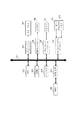
図1は本発明の第1の実施形態としてのパッチ画像出力/測色装置のシステム構成を示すブロック図である。前記構成において、101はCPU、102はROM、103はメインメモリ、104はSCSIインタフェース、105はHDD、106はグラフィックアクセラレータ、107はカラーモニタ、108はUSBコントローラ、109はカラープリンタ、110はパラレルポートコントローラ、111はスキャナ、112はキーボード/マウスコントローラ、113はキーボード、114はマウス、115はPCIバスである。なお、CPU101は、ROM102ならびにHDD105に保持されたプログラム/データに従い、後述の各種処理を実行する。
【0015】
上記構成において、ユーザがパッチの出力を行うよう、キーボード113とマウス114とを介してCPU101に指示すると、CPU101はHDD105よりパッチ作成プログラムを読み出し、パッチ作成プログラム内に格納されているアルゴリズムに従って少なくとも1枚のパッチ画像を作成する。アルゴリズムについては、後述する。作成されたパッチ画像はメインメモリ103に格納される。他方、パッチ画像における色配置順序はHDD105に格納される。この後、CPUは、メインメモリ103に保持されているパッチ画像をPCIバス115とUSBコントローラ108とを介してプリンタ109に転送し、指定されたモードにおける出力を指示する。プリンタ109は、指示によってパッチ画像を出力する。続いて、ユーザは出力されたパッチ印字を規定の用紙向きにてスキャナ111にセットした後、キーボード113とマウス114とを介してCPU101にパッチ測定を行うよう指示する。CPU101はこの指示に基づき、PCIバス115とパラレルポートコントローラ110とを介してスキャナ111にパッチ画像のスキャンを実行するよう指令する。指令に基づいてスキャンされたスキャン画像は、パラレルポートコントローラとPCIバスとを介して、スキャナ111よりメインメモリ103に転送される。メインメモリ103へのスキャン画像の転送が終了すると、CPU101はメインメモリ103内のスキャン画像に対して画像処理を行い、各パッチの検出と色信号情報の取得とを行い、結果であるパッチの色信号情報をHDD105に格納する。以上の動作が終了すると、CPU101はHDD105よりパッチ色信号情報とパッチ画像における色配置順序とを読み出し、前記色信号情報に対してプログラムにより指示されるアルゴリズムに従って情報処理を行い、情報処理結果をパッチ測色結果としてHDD105に格納し、動作を完了する。アルゴリズムについては、後述する。
【0016】
HDD105に格納された情報処理結果は、上述したカラープリンタのプリンタモデルの作成やキャリブレーションに使用される。
【0017】
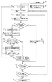
次に、パッチ作成アルゴリズムについて、図2を用いて説明する。アルゴリズムは、大きくは2つのループから成る。ステップ203からステップ212を経てステップ203へ戻るループ(以下、配色ループ)では、パッチとして出力する全ての色について、それぞれ1回に限り色の配置を行う。前述した配色ループを含むステップ202からステップ213を経てステップ202へ戻るループ(以下、メインループ)では、前述の配色動作を複数回繰り返すことにより、全ての色に対して複数回の出力を行った1枚のパッチ画像を作成する。以下、各ステップの詳細について述べる。
【0018】
201は、パッチ作成に当たって作業メモリ領域の確保、作業用変数の初期化等を行う。202は、配色ループにおいて、色を配置していく順番(以下、配色順)をランダムに定める。203は、ステップ202にて定めた配色順と配色ループにおける繰り返し回数とから、配置する色(配置色)を決定する。
【0019】
201は、パッチ作成に当たって作業メモリ領域の確保、作業用変数の初期化等を行う。作業用変数には、配置色の種類や配色ループの繰り返し回数等が含まれる。
【0020】
配置色の種類や配色ループの繰り返し回数は、本実施形態のパッチ作成アルゴリズムを実現するソフトウェアのユーザーインターフェースを用いてユーザが指示できるようにしても構わない。作成するパッチ数が増えると、その後の処理を高精度に行うことができるが、パッチ作成および測色にかかる時間が増大する。
【0021】
よって、ユーザが各種条件を指示することができるようにすることによってユーザの用途に応じたパッチ形成を行うことができる。
【0022】
204は、当該配置色Cpにおける配置不許可領域を求める。
【0023】
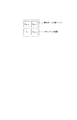
ノイズは主走査方向および副走査方向について相関があることが実験の結果わかった。このことに基づく本実施形態における配置不許可領域Afの導出方法について図3を用いて説明する。
【0024】
配置不許可領域Afは下記の主走査方向の領域および副走査方向の領域の2領域の和として求める。
領域1:既に色が配置されている領域Au。図3における格子模様領域。
領域2:当該配置色Cpの配置にあたって、既に配置されている当該色パッチと相関が高い領域Ac。図3における斜線領域。
【0025】
ここで、図3におけるTh_m(Cp)並びにTh_s(Cp)はそれぞれ、あらかじめ計算された当該色における主走査方向での閾値、副走査方向における閾値である。閾値Th_m(Cp)並びに閾値Th_s(Cp)の導出方式については後述する。
【0026】
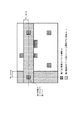
205は、パッチ配置全領域Aより配置不許可領域Afを除いた配置可能領域Aaを算出する。図3に示す領域Auならびに領域Acが得られ、これら2領域から配置不許可領域Afが与えられた場合の配置可能領域Aaを図4に示す。Aaが空である場合、ステップ206へ飛び、Aaが空でない場合にはステップ212へ飛ぶ。
【0027】
206は、配置候補領域Aeを、領域Aより領域Acを減じた領域とする。領域Acが図5に示す領域である場合、配置候補領域Aeは図6の様になる。207は、配置候補領域Aeにおいて、当該配置色の配置候補個所をランダムに定める。208は、配置候補個所において既に配置されているパッチ(以下、再配置パッチ)の色Ceを取得する。取得した色Ceにおいて、再配置可能かどうか判断する。前記判断について、図7ならびに図8を用いて説明する。
【0028】
配置候補個所を除いて既に配置されているCe色パッチと相関が高い領域Ac_cを算出する。この領域と既に色が配置されている領域Auとの和の領域Ac_sを求めた後、パッチ配置全領域Aより領域Ac_sを除いた再配置可能領域Ac_aを算出する。例えば、領域Ac_sが図7の様に与えられる時、再配置可能領域Ac_aは図8に示すような領域となる。このAc_aが空であるならば、再配置不可能と判断し、空でないならば再配置可能と判断する。
【0029】
判断結果が再配置可能である場合211へ飛び、再配置不可能である場合209へ飛ぶ。
【0030】
209は、配置候補領域Aeより、配置候補個所を減ずる。210は、領域Aeが空となった場合、パッチ作成が失敗したものとみなしてステップ201へ飛ぶ。
【0031】
空でない場合はステップ207へ飛ぶ。211は、再配置パッチを領域Ac_aにおいてランダムに再配置した後、当該配置色を配置候補個所へ配置する。この後、ステップ213へ飛ぶ。
【0032】
212は、配置可能領域Aaにおいて、当該配置色をランダムに配置する。配置後、ステップ213へ飛ぶ。213は、パッチとして用いる全色についてパッチ配置を完了した場合、ステップ214へ飛ぶ。完了していない場合は、ステップ203へ飛ぶ。214は、全色パッチ配置の実行回数が規定回数に達した場合、ステップ215へ飛ぶ。達していない場合にはステップ202へ飛ぶ。215でパッチ画像作成が完了する。
【0033】
以下において、各パッチ色における主走査方向での閾値Th_mと副走査方向における閾値Th_sとの導出方式について説明する。それぞれの色ごとに、閾値Th_mはノイズと主走査方向との相関とノイズの分散とから求められ、閾値Th_sはノイズと副走査方向との相関とノイズの分散とから求められる。
【0034】
閾値Th_mを計算するにあたり、まずノイズと主走査方向との相関関数fm(x)を下式の様に計算する。ここで、n(s,t)はx方向s位置、y方向t位置でのノイズ信号を表すものであり、Rmは正規化定数である。
【0035】
【外1】

次に、相関関数fm(x)をノイズの分散vにより下式のように正規化し、関数fmn(x)を求める。
【0037】
fmn(x)=fm(x)v
ここで、fmn(x)がある閾値以下となるxを求め、このxを閾値Th_mと定める。この関係を図9に示す。本実施形態では、閾値は予め実験により求められている値を用いる。
【0038】
閾値Th_sを計算するにあたり、まずノイズと副走査方向との相関関数fs(y)を下式の様に計算する。ここでRsは正規化定数である。
【0039】
【外2】
次に、相関関数fs(y)をノイズの分散vにより下式のように正規化し、関数fsn(y)を求める。
fsn(x)=fs(x)/v
ここで、fsn(y)がある閾値以下となるxを求め、このyを閾値Th_sと定める。この関係を図10に示す。
【0041】
次に、以下においてパッチ色信号情報に対する情報処理のアルゴリズムについて説明する。パッチ画像形成において各色につきn回パッチを用いて画像形成してパッチ画像の出力を行うと、前記パッチ画像を測定したパッチ色信号情報は各色においてnサンプル得られる。ここで、色Cにおけるiサンプル目のパッチ色信号情報をs(C,i)とすると、情報処理結果c(C)は次のように平均計算される。
【0042】
【外3】
【0043】
本実施例によれば、パッチ画像作成にあたって各パッチ色ごとのノイズの自己相関を考慮したパッチ配置を行うことにより、パッチ測定においてノイズによる影響を緩和し効率ならびに精度を向上させることが可能となる。
【0044】
〈第2実施形態〉
本実施形態は、第1実施形態におけるパッチ作成アルゴリズム動作に変更を加え、複数枚にわたるパッチ画像作成を可能としたものである。そこで、図2を用いてパッチ作成アルゴリズムのみ説明をする。
【0045】
201は、パッチ作成に当たって作業メモリ領域の確保、作業用変数の初期化を行う。202は、配色ループにおいて、色を配置していく順番(以下、配色順)をランダムに定める。
【0046】
203は、ステップ202にて定めた配色順と配所クループにおける繰り返し回数とから、配置する色(配置色)Cpを決定する。
【0047】
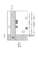
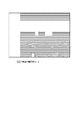
204は、当該配置色Cpにおける配置不許可領域を求める。配置不許可領域Afの導出方法について図11を用いて説明する。配置不許可領域Afは下記の2領域の和として求める。
領域1:全てのページに渡って既に色が配置されている領域Aua。図11における格子模様領域。
領域2:当該配置色Cpの配置にあたって、既に配置されている当該色パッチと相関が高い領域Ac。
図11における斜線領域。
下記の領域については、或るページにおいてパッチが配置されていたとしても別ページにて同領域に配置が可能であるため、配置不許可領域Afには含めない。
領域3:一部のページにて色が配置されている領域Aup。図11における網点模様領域。
但、図11におけるTh_m(Cp)並びにTh_s(Cp)はそれぞれ、あらかじめ計算された当該色における主走査方向での閾値、副走査方向における閾値である。
【0048】
205は、パッチ配置全領域Aより配置不許可領域Afを除いた配置可能領域Aaを算出する。図11を配置不許可領域Afとしたときの配置可能領域Aaを図12に示す。Aaが空である場合、ステップ206へ飛び、Aaが空でない場合にはステップ212へ飛ぶ。
【0049】
206は、配置候補領域Aeを、領域Aより領域Acを減じた領域とする。207は、配置候補領域Aeにおいて、当該配置色の配置候補ページと配置候補個所とをランダムに定める。
【0050】
208は、配置候補ページと配置候補個所とにおいて既に配置されているパッチ(以下、再配置パッチ)の色Ceを取得する。取得した色Ceにおいて、再配置可能かどうか判断する。前記判断について、図13ならびに図14を用いて説明する。
【0051】
配置候補個所を除いて既に配置されているCe色パッチと相関が高い領域Ac_cを算出する。この領域と、全てのページに渡って色が配置されている領域Auaとの和の領域Ac_sを求めた後、パッチ配置全領域Aより領域Ac_sを除いた再配置可能領域Ac_aを算出する。例えば、領域Ac_sが図13の様に与えられる時、再配置可能領域Ac_aは図14に示すような領域となる。このAc_aが空であるならば、再配置不可能と判断し、空でないならば再配置可能と判断する。
【0052】
判断結果が再配置可能である場合211へ飛び、再配置不可能である場合209へ飛ぶ。209は、配置候補領域Aeより、配置候補個所を減ずる。210は、領域Aeが空となった場合、パッチ作成が失敗したものとみなしてステップ201へ飛ぶ。空でない場合はステップ207へ飛ぶ。211は、配置候補個所の色CeパッチAc_aにおいてランダムに再配置する。配置個所に既に色が配置されているページは除外して、配置ページもランダムに決定する。以上の処理の後、当該配置色を配置候補個所へ配置する。この後、領域ステップ213へ飛ぶ。
【0053】
212は、配置可能領域Aaにおいて、当該配置色をランダムに配置する。配置個所に既に色が配置されているページは除外して、配置ページもランダムに決定する。配置後、ステップ213へ飛ぶ。
【0054】
213は、パッチとして用いる全色についてパッチ配置を完了した場合、ステップ214へ飛ぶ。完了していない場合は、ステップ203へ飛ぶ。214は、全色パッチ配置の実行回数が規定回数に達した場合、ステップ215へ飛ぶ。達していない場合にはステップ202へ飛ぶ。215は、パッチ画像作成を完了する。
【0055】
本実施形態によれば、複数枚のパッチ画像を作成することにより第1実施形態と比較して精度を向上させることができる。
【0056】
〈第3実施形態〉
本実施形態は第1実施形態におけるパッチ作成アルゴリズムを変更したものである。そこで、パッチ作成アルゴリズムのみについて、図15を用いて以下で説明する。
【0057】
図15に示すアルゴリズムは、大きくは2つのループから成る。305から311を経て306へ戻るループ(以下、配色ループ)では、基本パッチ画像に対してローテイト動作を施した画像(以下、ローテイト画像)を複数または1つ配置することにより1枚のパッチ画像作成を行う。前述の配色ループを含む304から313を経て305へ戻るループ(以下、メインループ)では、配色ループを複数回もしくは1回実行することにより複数枚もしくは1枚のパッチ画像作成を実現する。以下、各ステップの詳細について述べる。
【0058】
301は、パッチ作成に当たって作業メモリ領域の確保、作業用変数の初期化等を行う。302は、変数L、M、Nを決定する。Lはパッチ画像の枚数を表す。MとNとは、1枚のパッチ画像におけるローテイト画像の配置数を定めるものであり、Mはy方向でのローテイト画像の配置数、Nはx方向でのローテイト画像の配置数を定める。すなわち、1枚のパッチ画像におけるローテイト画像の配置数はM×Nとなる。
【0059】
303は、基本パッチ画像Iorgを作成する。基本パッチ画像Iorgは、y方向にI個、x方向にJ個パッチが配置された画像であり、全体としてI×J個のパッチを含む。尚、パッチの大きさはPx×Pyとする。304は、l=0とする。305は、m=0とする。306は、n=0とする。
【0060】
307は、基本パッチ画像Iorgに対してローテイト動作を施し、ローテイト画像Inmlを作成する。X方向のローテイト量Rxとy方向Ryのローテイト量とはそれぞれlとmとnとから決定され、次のように計算される。ここで、〔・〕は切り捨て動作による整数化を行う関数である。
【0061】
【外4】
基本パッチ画像とローテイト画像Inmlとの関係を図16に示す。
【0063】
308は、ステップ307によるローテイト画像Inmlを所定の位置に配置する。ここでローテイト画像Inmlの左上端の位置は、図17に示すようにパッチ画像左上端から測定して右にPx×J×n移動し、下にPy×I×m移動した位置となる。
【0064】
309は、現在のnの値がN−1と等しければ、311へ飛ぶ。等しくない場合には310へ飛ぶ。310は、現在のnの値に1を加算した後、307へ飛ぶ。311は、現在のmの値がM−1と等しければ、313へ飛ぶ。等しくない場合には312へ飛ぶ。312は、現在のnの値に1を加算した後、306へ飛ぶ。313は、現在のlの値がL−1と等しければ、315へ飛ぶ。等しくない場合には314へ飛ぶ。314は、現在のlの値に1を加算した後、305へ飛ぶ。315は、パッチ画像作成を完了する。
【0065】
本実施形態によれば、簡便にパッチ画像作成ができる上、規則的な配列を行うことにより全ての色について平均的にノイズの影響を緩和することが可能となる。また、精度とパッチ画像枚数との関係が明らかである為、ユーザが精度と煩雑さとの選択判断を容易にするものである。さらに規則的に配置したことにより配置順序情報も大幅に削減できる。
【0066】
〈第4実施形態〉
本実施形態は第1実施形態におけるパッチ作成アルゴリズムを変更したものである。そこで、パッチ作成アルゴリズムを図18〜図25を用いて説明する。
【0067】
本実施形態は、複数個のパッチを含むブロック画像を形成した後に、ブロック画像を配置することにより、パッチ配置にかかる計算負荷を転減するものである。
【0068】
次に、パッチ作成アルゴリズムについて、図18を用いて説明する。アルゴリズムは、大きくは2つのループから成る。ステップ404からステップ415を経てステップ404へ戻るループ(以下、配置ループ)では、全ブロックについて、それぞれ1回に限り色の配置を行う。前述した配置ループを含むステップ403からステップ416を経てステップ403へ戻るループ(以下、メインループ)では、前述の配置動作を複数回繰り返すことにより、全ブロックに対して複数回の出力を行った複数ページに渡るパッチ画像を作成する。以下、各ステップの詳細について述べる。
【0069】
201は、パッチ作成に当たって作業メモリ領域の確保、作業用変数の初期化等を行う。
【0070】
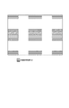
202は、複数のパッチを含むブロック画像(以下ブロック)を、任意のブロックの積集合が空であり、全ブロックの和集合が全パッチの集合となるよう形成する。1例として、1000色のパッチを作成する際のブロック作成ルールを説明する。まず、各色パッチに対してパッチ番号1〜1000を割り当てる。次に、パッチ番号4i−3、4i−2、4i−1、4iを番号iのブロックを図19の様に割り当てて配置し、各ブロックの画像を形成する。これにより、250個のブロックが形成される。
【0071】
403は、ブロック配置に当たって作業メモリ領域の確保、作業用変数の初期化等を行う。
【0072】
404は配色ループにおいて、ブロックを配置していく順番(以下、配色順)をランダムに定める。
【0073】
405は、ステップ204にて定めた配色順と配色ループにおける繰り返し回数とから、配置するブロック(配置ブロック)Bpを決定する。
【0074】
406は、当該配置ブロックBpにおける配置不許可領域を求める。配置不許可領域Afの導出方法について後述する。配置不許可領域Afは下記の2領域の和として求める。
【0075】
領域1:全てのページに渡って既にブロックが配置されている領域Aua。図20における格子模様領域。
【0076】
領域2:当該配置ブロックBpの配置にあたって、既に配置されている当該ブロックと相関が高い領域Aua。図20における斜線領域。
【0077】
下記の領域については、或るページにおいてブロックが配置されていたとしても別ページにて同領域に配置が可能であるため、配置不許可領域Afには含めない。
【0078】
領域3:一部のページにてブロックが配置されている領域Aup。図20における網点模様領域。
但し、図20におけるTh_mb(Bp)並びにTh_sb(Bp)はそれぞれ、あらかじめ計算された当該ブロックにおける主走査方向での閾値、副走査方向における閾値である。閾値Th_mb(Bp)並びに閾値Th_sb(Bp)の導出方式については後述する。
【0079】
407は、ブロック配置全領域Aより配置不許可領域Afを除いた配置可能領域Aaを算出する。図20を配置不許可領域Afとしたときの配置可能領域Aaを図21に示す。Aaが空である場合、ステップ408へ飛び、Aaが空でない場合にはステップ414へ飛ぶ。
【0080】
408は、配置候補領域Aeを、領域Aより領域Acを減じた領域とする。領域Acが図22に示す領域である場合、配置候補領域Aeは図23の様になる。
【0081】
409は、配置候補領域Aeにおいて、当該配置色の配置候補ページと配置候補箇所とをランダムに定める。
【0082】
210は、配置候補ページと配置候補個所とにおいて既に配置されているブロック(以下、再配置ブロック)の番号Beを取得する。取得したブロックBeにおいて、再配置可能かどうか判断する。前記判断について、図24ならびに図25を用いて説明する。
【0083】
配置候補個所を除いて既に配置されているBeブロックと相関が高い領域Ac_cを算出する。この領域と、全てのページに渡ってブロックが配置されている領域Auaとの和の領域Ac_sを求めた後、パッチ配置全領域Aより領域Ac_sを除いた再配置可能領域Ac_aを算出する。例えば、領域Ac_sが図24の様に与えられる時、再配置可能領域Ac_aは図25に示すような領域となる。このAc_aが空であるならば、再配置不可能と判断し、空でないならば再配置可能と判断する。
【0084】
判断結果が再配置可能である場合211へ飛び、再配置不可能である場合409へ飛ぶ。
【0085】
411は、配置候補領域Aeより、配置候補個所を減ずる。
【0086】
412は、領域Aeが空となった場合、ブロック配置に失敗したものとみなしてステップ403へ飛ぶ。空でない場合はステップ409へ飛ぶ。
【0087】
413は、配置候補個所のブロックBeをAc_aにおいてランダムに再配置する。配置個所に既にブロックが配置されているページは除外して、配置ページもランダムに決定する。以上の処理の後、当該配置ブロックを配置候補個所へ配置する。この後、領域ステップ415へ飛ぶ。
【0088】
414は、配置可能領域Aaにおいて、当該配置ブロックをランダムに配置する。配置個所に既にブロックが配置されているページは除外して、配置ページもランダムに決定する。配置後、ステップ415へ飛ぶ。
【0089】
415は、全ブロックについてブロック配置を完了した場合、ステップ416へ飛ぶ。完了していない場合は、ステップ405へ飛ぶ。
【0090】
416は、全色ブロック配置の実行回数が規定回数に達した場合、ステップ417へ飛ぶ。達していない場合にはステップ204へ飛ぶ。
【0091】
417は、パッチ画像作成を完了する。
【0092】
以下において、各ブロックにおける主走査方向での閾値Th_mb(Bp)と副走査方向における閾値Th_sb(Bp)との導出方式について説明する。
【0093】
まずパッチ全色についてそれぞれの色ごとに、閾値Th_m(Cp)と閾値Th_s(Cp)とを求める。閾値Th_m(Cp)はノイズと主走査方向との相関とノイズの分散とから求められ、閾値Th_s(Cp)はノイズと副走査方向との相関とノイズの分散とから求められる。色パッチCpに対する閾値Th_m(Cp)を計算するにあたっては、まずノイズと主走査方向との相関関数fm(x)を下式の様に計算する。ここで、n(s,t)はx方向s位置、y方向t位置でのノイズ信号を表すものであり、Rmは正規化定数である。
【0094】
【外5】
次に、相関関数fm(x)をノイズの分散vにより下式のように正規化し、関数fmn(x)を求める。
fmn(x)=fm(x)/v
【0096】
ここで、fmn(x)がある閾値以下となるxを求め、このxを色パッチCpに対する閾値Th_m(Cp)と定める。この関係を図9に示す。色パッチCpに対する閾値Th_s(Cp)を計算するにあたっては、まずノイズと副走査方向との相関関数fs(y)を下式の様に計算する。ここでRsは正規化定数である。
【0097】
【外6】
次に、相関関数fs(y)をノイズの分散vにより下式のように正規化し、関数fsn(y)を求める。
fsn(x)=fs(x)/v
【0099】
ここで、fsn(y)がある閾値以下となるxを求め、このyを色パッチCpに対する閾値Th_s(Cp)と定める。この関係を図10に示す。
【0100】
以上の様にパッチ全色についてそれぞれの色ごとに、閾値Th_m(Cp)と閾値Th_s(Cp)とを求めた後、各ブロックにおける主走査方向での閾値Th_mb(Bp)と副走査方向における閾値Th_sb(Bp)とを次の様に導出する。ブロックBpにはn個の色パッチCj、Cj+1、・・・、Cj+n-1が含まれているとすると、
Th_mb(Bp)=Max(Th_m(Cj),Th_m(Cj+1),・・・,Th_m(Cj+n-1))
Th_sb(Bp)=Max(Th_s(Cj),Th_s(Cj+1),・・・,Th_s(Cj+n-1))
【0101】
すなわち、Th_mb(Bp)は、自身に含まれる色パッチにおける主走査方向閾値の最大値から決定され、Th_sb(Bp)は、自身に含まれる色パッチにおける副走査方向閾値の最大値から決定される。
【0102】
次に、以下においてパッチ色信号情報に対する情報処理のアルゴリズムについて説明する。パッチ画像作成に於いて各色につきn回パッチを用いて画像作成してパッチ画像の出力を行うと、前記パッチ画像を測定したパッチ色信号情報は各色においてnサンプル得られる。ここで、色Cにおけるiサンプル目のパッチ色信号情報をs(C,i)とすると、情報処理結果e(C)は次のように平均計算される。
【0103】
【外7】
この情報処理結果c(C)をパッチ測色結果とする。
【0105】
本実施形態によれば、各パッチ色ごとのノイズの自己相関を考慮したパッチ配置を複数枚に渡って行うことでパッチ画像作成することにより、パッチ測定においてノイズによる影響を緩和し精度を向上させることが可能となる。さらに本実施形態においては、パッチ画像を複数個あつめたブロックを形成した後パッチ画像を形成することにより、精度を保ったまま、パッチ画像作成時間の短縮ならびにパッチ配置順序情報の削減が可能となる。
【0106】
以上説明した様に、上述の第1〜第4の各実施形態によれば以下の効果を得ることができる。
【0107】
パッチ画像において用いる全ての色において各パッチの色におけるノイズの相関を考慮し、同一色につき複数個のパッチを配置したパッチ画像を作成する。ここで、同パッチ色におけるノイズの自己相関によるノイズ同士の相互の影響を小さくするよう、パッチを配置することにより、同パッチ色におけるノイズを等価的に白色雑音と近似できる。従って、測定情報の平均化によって混入したノイズを除去することが可能となる。
【0108】
すなわち、測定情報の平均化によってノイズの影響を緩和することを少ないパッチ画像により可能とするパッチ画像を作成することができる。
【0109】
〈他の実施形態〉
また前述した実施形態の機能を実現する様に各種のデバイスを動作させる様に該各種デバイスと接続された装置あるいはシステム内のコンピュータに、前記実施形態機能を実現するためのソフトウエアのプログラムコードを供給し、そのシステムあるいは装置のコンピュータ(CPUあるいはMPU)を格納されたプログラムに従って前記各種デバイスを動作させることによって実施したものも本発明の範疇に含まれる。
【0110】
またこの場合、前記ソフトウエアのプログラムコード自体が前述した実施形態の機能を実現することになり、そのプログラムコード自体、及びそのプログラムコードをコンピュータに供給するための手段、例えばかかるプログラムコードを格納した記憶媒体は本発明を構成する。
【0111】
かかるプログラムコードを格納する記憶媒体としては例えばフロッピーディスク、ハードディスク、光ディスク、光磁気ディスク、CD−ROM、磁気テープ、不揮発性のメモリカード、ROM等を用いることが出来る。
【0112】
またコンピュータが供給されたプログラムコードを実行することにより、前述の実施形態の機能が実現されるだけではなく、そのプログラムコードがコンピュータにおいて稼働しているOS(オペレーティングシステム)あるいは他のアプリケーションソフト等と共同して前述の実施形態の機能が実現される場合にもかかるプログラムコードは本発明の実施形態に含まれることは言うまでもない。
【0113】
更に供給されたプログラムコードが、コンピュータの機能拡張ボードやコンピュータに接続された機能拡張ユニットに備わるメモリに格納された後そのプログラムコードの指示に基づいてその機能拡張ボードや機能格納ユニットに備わるCPU等が実際の処理の一部または全部を行い、その処理によって前述した実施形態の機能が実現される場合も本発明に含まれることは言うまでもない。
【0114】
【発明の効果】
本発明は、ノイズの相関を考慮しつつ、できるだけ少ないパッチ画像によりノイズの影響を緩和できるようにパッチ画像を作成することができる。
【図面の簡単な説明】
【図1】第1の実施形態としてのパッチ画像出力/測色装置のシステム構成を示すブロック図である。
【図2】第1の実施形態としてのパッチ画像作成方法のアルゴリズムを示すフローチャートである。
【図3】第1の実施形態における配置禁止領域の一例を表す図である。
【図4】第1の実施形態における配置可能領域の一例を表す図である。
【図5】第1の実施形態における配置禁止領域の一例を表す図である。
【図6】第1の実施形態における配置候補領域の一例を表す図である。
【図7】第1の実施形態における、再配置パッチでの配置禁止領域の一例を表す図である。
【図8】第1の実施形態における、再配置パッチでの配置可能領域の一例を表す図である。
【図9】第1の実施形態において、ある色において混入する雑音色信号の主走査方向の自己相関関数の模式図を示すものであり、ある閾値と主走査方向での閾値Th_mとの関係を示す模式図である。
【図10】第1の実施形態において、ある色において混入する雑音色信号の副走査方向の自己相関関数の模式図を示すものであり、ある閾値と副走査方向での閾値Th_sとの関係を示す模式図である。
【図11】第2の実施形態における配置禁止領域の一例を表す図である。
【図12】第2の実施形態における配置候補領域の一例を表す図である。
【図13】第2の実施形態における、再配置パッチでの配置禁止領域の一例を表す図である。
【図14】第2の実施形態における、再配置パッチでの配置可能領域の一例を表す図である。
【図15】第3の実施形態としてのパッチ画像作成方法のアルゴリズムを示すフローチャートである。
【図16】第3の実施形態における、基本パッチ画像とローテイト画像との模式図である。
【図17】第3の実施形態における、ローテイト画像の配置位置を示す模式図である。
【図18】第4の実施形態としてのパッチ画像作成方法のアルゴリズムを示すフローチャートである。
【図19】第4の実施形態において、あるブロック画像におけるパッチの配置状態を表す図である。
【図20】第4の実施形態における配置禁止領域の一例を表す図である。
【図21】第4の実施形態における配置可能領域の一例を表す図である。
【図22】第4の実施形態における配置禁止領域の一例を表す図である。
【図23】第4の実施形態における配置候補領域の一例を表す図である。
【図24】第4の実施形態における、再配置ブロックでの配置禁止領域の一例を表す図である。
【図25】第4の実施形態における、再配置ブロックでの配置可能領域の一例を表す図である。[0001]
BACKGROUND OF THE INVENTION
The present invention relates to an apparatus for creating a patch image.
[0002]
[Prior art]
In recent years, color DTP based on computer systems has become widespread along with improvements in computer color expression and color printer performance. Here, techniques such as calibration of a color printer aiming at realizing more accurate color expression and creation of a printer model of a color printer aiming at realizing more accurate color matching are used. However, in any technique, it is necessary to take steps such as creating a patch image, outputting the created patch image, and measuring the output patch image. However, since noise is always mixed in the output of the patch image, accurate patch image measurement is impossible. Therefore, conventionally, assuming that the noise is white noise, the influence of the noise is mitigated by outputting and measuring a plurality of the same patch images. Alternatively, a technique is used in which a patch image is subjected to a rotation process, and a plurality of outputs are output and measured to mitigate the influence of noise.
[0003]
[Problems to be solved by the invention]
However, since a noise color signal (hereinafter referred to as noise) mixed in the patch image has a strong correlation between the color and position of the patch, it cannot be approximated to white noise. Therefore, even if a large number of the same images are output, there is a limit in reducing the influence of noise. Therefore, it is necessary to create a patch image in consideration of noise correlation. For practical convenience, it is preferable that the number of patch images is as small as possible. Therefore, there is a need for a patch image creation method that can reduce the influence of noise with as few patch images as possible while taking into account noise correlation.
[0004]
The present invention has been made in view of the above-described problem, and an object thereof is to reduce the influence of noise with as few patch images as possible while considering the correlation of noise.
[0005]
[Means for Solving the Problems]
In order to achieve the above object, the present invention has the following constituent features.
[0006]
The first invention of the present application is a patch image used for generating image processing data, and is a patch image generation method for generating a patch image including a plurality of patches related to the same color, and determines an arrangement color Within a predetermined distance in the main scanning direction and the sub-scanning direction, the determination step, the area where the color patch is already arranged, and the arrangement position of the already arranged color patch having the same color as the decided arrangement color A setting step for setting the region as a non-permitted region, a calculation step for calculating a dispositionable region excluding the set disapproval region from the entire patch disposition region, and the determination as the calculated dispositionable region An arrangement step of arranging color patches of the arranged colors, and repeating the determination step, the setting step, the calculation step and the arrangement step, Characterized in that it created.
A second invention of the present application is a patch image used to generate image processing data, and is a patch image creation method for creating a patch image including a plurality of patches relating to the same color, and a plurality of patches to be arranged A determination step of determining a block image including the patch color of the image, a region where the block image is already arranged, and an arrangement position of the already arranged block image having the same block image as the decided block image; A setting step of setting an area within a predetermined distance in the main scanning direction and the sub-scanning direction as an arrangement non-permission area, and a calculation step of calculating an arrangement possible area excluding the set non-permission area from the entire patch arrangement area And an arrangement step of arranging the determined block image in the calculated arrangementable area, the determination step, the setting step, By repeating the calculating step and the disposing step, characterized in that to create the patch image.
[0010]
DETAILED DESCRIPTION OF THE INVENTION
Hereinafter, an embodiment according to a system configuration of a patch image output / colorimetry apparatus will be described with reference to the drawings.
[0011]
The system of the patch image output / colorimetry apparatus is used when generating image processing data such as creating a printer model of a color printer and calibrating color correction conditions.
[0012]
Calibration is to output a desired test patch with a color printer, measure the color of the output test patch, determine the current color reproduction characteristics of the color printer from the color measurement result, and optimize the color correction conditions. is there.
[0013]
Therefore, when the following embodiment is applied to calibration, it is used when outputting a desired test patch.
[0014]
<First Embodiment>
FIG. 1 is a block diagram showing a system configuration of a patch image output / colorimetric apparatus as a first embodiment of the present invention. In the above configuration, 101 is a CPU, 102 is a ROM, 103 is a main memory, 104 is a SCSI interface, 105 is an HDD, 106 is a graphic accelerator, 107 is a color monitor, 108 is a USB controller, 109 is a color printer, and 110 is a parallel port. A controller, 111 is a scanner, 112 is a keyboard / mouse controller, 113 is a keyboard, 114 is a mouse, and 115 is a PCI bus. The
[0015]
In the above configuration, when the user instructs the
[0016]
The information processing result stored in the HDD 105 is used for creating and calibrating the printer model of the color printer described above.
[0017]
Next, the patch creation algorithm will be described with reference to FIG. The algorithm consists largely of two loops. In a loop from
[0018]
201 prepares a work memory area, initializes work variables, and the like for patch creation. In 202, a color arrangement loop randomly determines the order in which colors are arranged (hereinafter, color arrangement order). 203 determines a color (arrangement color) to be arranged from the color arrangement order determined in
[0019]
201 prepares a work memory area, initializes work variables, and the like for patch creation. The work variables include the type of arrangement color and the number of repetitions of the arrangement loop.
[0020]
The user may specify the type of arrangement color and the number of repetitions of the arrangement loop using the user interface of software that implements the patch creation algorithm of the present embodiment. If the number of patches to be created increases, the subsequent processing can be performed with high accuracy, but the time required for patch creation and color measurement increases.
[0021]
Therefore, by allowing the user to instruct various conditions, it is possible to perform patch formation according to the user's application.
[0022]
204 obtains an arrangement non-permitted area for the arrangement color Cp.
[0023]
As a result of experiments, it was found that noise has a correlation in the main scanning direction and the sub-scanning direction. A method for deriving the non-permitted area Af in this embodiment based on this will be described with reference to FIG.
[0024]
The arrangement non-permission area Af is obtained as the sum of the following two areas: a main scanning direction area and a sub scanning direction area.
Area 1: An area Au in which colors are already arranged. The lattice pattern area | region in FIG.
Region 2: A region Ac that has a high correlation with the color patch that has already been arranged when the arrangement color Cp is arranged. The hatched area in FIG.
[0025]
Here, Th_m (Cp) and Th_s (Cp) in FIG. 3 are a threshold value in the main scanning direction and a threshold value in the sub-scanning direction for the color calculated in advance, respectively. A method for deriving the threshold Th_m (Cp) and the threshold Th_s (Cp) will be described later.
[0026]
In step 205, an allocatable area Aa obtained by removing the non-permitted area Af from the entire patch arrangement area A is calculated. The area Au and the area Ac shown in FIG. 3 are obtained, and the arrangement possible area Aa when the arrangement non-permission area Af is given from these two areas is shown in FIG. If Aa is empty, the process jumps to Step 206, and if Aa is not empty, the process jumps to Step 212.
[0027]
In 206, the arrangement candidate area Ae is an area obtained by subtracting the area Ac from the area A. When the area Ac is the area shown in FIG. 5, the arrangement candidate area Ae is as shown in FIG.
[0028]
A region Ac_c having a high correlation with the Ce color patch that has already been arranged is calculated except for the arrangement candidate portion. After obtaining the area Ac_s of the sum of this area and the area Au in which the color is already arranged, the re-arrangeable area Ac_a obtained by excluding the area Ac_s from the entire patch arrangement area A is calculated. For example, when the area Ac_s is given as shown in FIG. 7, the rearrangeable area Ac_a becomes an area as shown in FIG. If this Ac_a is empty, it is determined that relocation is not possible, and if it is not empty, it is determined that relocation is possible.
[0029]
If the determination result is rearrangeable, the process jumps to 211, and if the determination result is impossible, the process jumps to 209.
[0030]
In 209, the number of placement candidate locations is reduced from the placement candidate area Ae. If the area Ae becomes empty, the
[0031]
If it is not empty, the process jumps to step 207. 211, after rearranging the rearrangement patch randomly in the area Ac_a, arranges the arrangement color at the arrangement candidate location. Thereafter, the process jumps to step 213.
[0032]
212 arranges the arrangement color at random in the arrangement possible area Aa. After placement, jump to step 213. Step 213 jumps to step 214 when the patch arrangement is completed for all colors used as a patch. If not completed, the process jumps to step 203. If the number of executions of all-color patch arrangement reaches the specified
[0033]
Hereinafter, a method of deriving the threshold value Th_m in the main scanning direction and the threshold value Th_s in the sub-scanning direction for each patch color will be described. For each color, the threshold Th_m is obtained from the correlation between noise and the main scanning direction and the noise variance, and the threshold Th_s is obtained from the correlation between noise and the sub-scanning direction and the noise variance.
[0034]
In calculating the threshold Th_m, first, a correlation function fm (x) between noise and the main scanning direction is calculated as in the following equation. Here, n (s, t) represents a noise signal at the s position in the x direction and the t position in the y direction, and Rm is a normalization constant.
[0035]
[Outside 1]
Next, the correlation function fm (x) is normalized by the noise variance v as shown in the following equation to obtain the function fmn (x).
[0037]
fmn (x) = fm (x) v
Here, x where fmn (x) is equal to or less than a certain threshold is obtained, and this x is determined as a threshold Th_m. This relationship is shown in FIG. In this embodiment, the threshold value is obtained in advance through experiments.
[0038]
In calculating the threshold Th_s, first, the correlation function fs (y) between the noise and the sub-scanning direction is calculated as in the following equation. Here, Rs is a normalization constant.
[0039]
[Outside 2]
Next, the correlation function fs (y) is normalized by the noise variance v as shown in the following equation to obtain the function fsn (y).
fsn (x) = fs (x) / v
Here, x where fsn (y) is equal to or smaller than a certain threshold is obtained, and this y is determined as the threshold Th_s. This relationship is shown in FIG.
[0041]
Next, an information processing algorithm for patch color signal information will be described below. In patch image formation, when an image is formed using a patch n times for each color and the patch image is output, n samples of patch color signal information obtained by measuring the patch image are obtained for each color. Here, when the patch color signal information of the i-th sample in the color C is s (C, i), the information processing result c (C) is averaged as follows.
[0042]
[Outside 3]
[0043]
According to the present embodiment, by performing patch placement in consideration of the autocorrelation of noise for each patch color when creating a patch image, it is possible to reduce the influence of noise in patch measurement and improve efficiency and accuracy. .
[0044]
Second Embodiment
In the present embodiment, the patch creation algorithm operation in the first embodiment is changed, and a plurality of patch images can be created. Therefore, only the patch creation algorithm will be described with reference to FIG.
[0045]
201 secures a work memory area and initializes work variables when creating a patch. In 202, a color arrangement loop randomly determines the order in which colors are arranged (hereinafter, color arrangement order).
[0046]
203 determines the color (arrangement color) Cp to be arranged from the color arrangement order determined in
[0047]
204 obtains an arrangement non-permitted area for the arrangement color Cp. A method for deriving the non-permitted area Af will be described with reference to FIG. The non-permitted area Af is obtained as the sum of the following two areas.
Area 1: An area Aua in which colors are already arranged over all pages. The lattice pattern area | region in FIG.
Region 2: A region Ac that has a high correlation with the color patch that has already been arranged when the arrangement color Cp is arranged.
The hatched area in FIG.
The following areas are not included in the non-permitted area Af because patches can be arranged on another page even if patches are arranged on a certain page.
Area 3: Area Up where colors are arranged on some pages. The halftone dot pattern area | region in FIG.
However, Th_m (Cp) and Th_s (Cp) in FIG. 11 are a threshold value in the main scanning direction and a threshold value in the sub-scanning direction for the color calculated in advance.
[0048]
In step 205, an allocatable area Aa obtained by removing the non-permitted area Af from the entire patch arrangement area A is calculated. FIG. 12 shows an arrangement possible area Aa when FIG. 11 is an arrangement non-permission area Af. If Aa is empty, the process jumps to Step 206, and if Aa is not empty, the process jumps to Step 212.
[0049]
In 206, the arrangement candidate area Ae is an area obtained by subtracting the area Ac from the area
[0050]
208 obtains the color Ce of a patch that has already been arranged in the arrangement candidate page and the arrangement candidate portion (hereinafter, rearranged patch). It is determined whether or not the acquired color Ce can be rearranged. The determination will be described with reference to FIGS. 13 and 14.
[0051]
A region Ac_c having a high correlation with the Ce color patch that has already been arranged is calculated except for the arrangement candidate portion. After obtaining the sum area Ac_s of this area and the area Aua in which colors are arranged over all pages, a re-arrangeable area Ac_a obtained by excluding the area Ac_s from the entire patch arrangement area A is calculated. For example, when the region Ac_s is given as shown in FIG. 13, the rearrangeable region Ac_a becomes a region as shown in FIG. If this Ac_a is empty, it is determined that relocation is not possible, and if it is not empty, it is determined that relocation is possible.
[0052]
If the determination result is rearrangeable, the process jumps to 211, and if the determination result is impossible, the process jumps to 209. In 209, the number of placement candidate locations is reduced from the placement candidate area Ae. If the area Ae becomes empty, the
[0053]
212 arranges the arrangement color at random in the arrangement possible area Aa. The page where the color is already arranged at the arrangement location is excluded, and the arrangement page is also determined at random. After placement, jump to step 213.
[0054]
Step 213 jumps to step 214 when the patch arrangement is completed for all colors used as a patch. If not completed, the process jumps to step 203. If the number of executions of all-color patch arrangement reaches the specified
[0055]
According to the present embodiment, the accuracy can be improved by creating a plurality of patch images as compared with the first embodiment.
[0056]
<Third Embodiment>
This embodiment is a modification of the patch creation algorithm in the first embodiment. Therefore, only the patch creation algorithm will be described below with reference to FIG.
[0057]
The algorithm shown in FIG. 15 is roughly composed of two loops. In a loop from 305 to 311 and returning to 306 (hereinafter referred to as a color arrangement loop), a single patch image is created by arranging a plurality of or one image (hereinafter referred to as a “rotate image”) obtained by performing a rotation operation on the basic patch image I do. In a loop including the above-described color arrangement loop, which returns from 304 to 313 to 305 (hereinafter referred to as a main loop), a plurality of or one patch image is created by executing the color arrangement loop a plurality of times or once. Details of each step will be described below.
[0058]
301 prepares a work memory area, initializes work variables, and the like when creating a patch. 302 determines variables L, M, and N. L represents the number of patch images. M and N define the number of rotation images arranged in one patch image, M is the number of rotation images arranged in the y direction, and N is the number of rotation images arranged in the x direction. That is, the number of rotated images arranged in one patch image is M × N.
[0059]
303 creates a basic patch image Iorg. The basic patch image Iorg is an image in which I patches in the y direction and J patches in the x direction are arranged, and includes I × J patches as a whole. Note that the size of the patch is Px × Py. 304 sets l = 0. 305 sets m = 0. 306 sets n = 0.
[0060]
In
[0061]
[Outside 4]
FIG. 16 shows the relationship between the basic patch image and the rotated image Inml.
[0063]
In
[0064]
309 jumps to 311 if the current value of n is equal to N-1. If they are not equal, jump to 310. 310 jumps to 307 after adding 1 to the current value of n. 311 jumps to 313 if the current value of m is equal to M-1. If they are not equal, jump to 312. 312 jumps to 306 after adding 1 to the current value of n. 313 jumps to 315 if the current value of l is equal to L-1. If they are not equal, jump to 314. 314 jumps to 305 after adding 1 to the current value of l. In
[0065]
According to the present embodiment, it is possible to easily create a patch image, and it is possible to alleviate the influence of noise on average for all colors by performing regular arrangement. In addition, since the relationship between the accuracy and the number of patch images is clear, the user can easily select and judge between accuracy and complexity. Furthermore, the arrangement order information can be greatly reduced by the regular arrangement.
[0066]
<Fourth embodiment>
This embodiment is a modification of the patch creation algorithm in the first embodiment. The patch creation algorithm will be described with reference to FIGS.
[0067]
In the present embodiment, after a block image including a plurality of patches is formed, the block image is arranged to reduce the calculation load related to the patch arrangement.
[0068]
Next, the patch creation algorithm will be described with reference to FIG. The algorithm consists largely of two loops. In a loop from
[0069]
201 prepares a work memory area, initializes work variables, and the like for patch creation.
[0070]
In 202, a block image (hereinafter referred to as a block) including a plurality of patches is formed such that the product set of arbitrary blocks is empty and the union of all blocks is a set of all patches. As an example, a block creation rule for creating a 1000 color patch will be described. First, patch numbers 1-1000 are assigned to each color patch. Next, patch numbers 4i-3, 4i-2, 4i-1, and 4i are arranged by allocating blocks of number i as shown in FIG. 19, and an image of each block is formed. As a result, 250 blocks are formed.
[0071]
In
[0072]
[0073]
In
[0074]
In
[0075]
Area 1: Area Aua where blocks are already arranged over all pages. The lattice pattern area | region in FIG.
[0076]
Region 2: A region Aua having a high correlation with the already arranged block in arranging the arranged block Bp. The hatched area in FIG.
[0077]
The following areas are not included in the non-permitted area Af because even if a block is arranged on a certain page, it can be arranged in the same area on another page.
[0078]
Area 3: Area Up where blocks are arranged on some pages. The halftone dot pattern region in FIG.
However, Th_mb (Bp) and Th_sb (Bp) in FIG. 20 are respectively the threshold value in the main scanning direction and the threshold value in the sub-scanning direction, which are calculated in advance. A method for deriving the threshold Th_mb (Bp) and the threshold Th_sb (Bp) will be described later.
[0079]
In
[0080]
[0081]
[0082]
210 obtains the number Be of a block already arranged in the arrangement candidate page and the arrangement candidate portion (hereinafter, rearranged block). It is determined whether or not rearrangement is possible in the acquired block Be. The determination will be described with reference to FIGS. 24 and 25. FIG.
[0083]
A region Ac_c having a high correlation with the Be block that has already been arranged is calculated except for the arrangement candidate portion. After obtaining the sum area Ac_s of this area and the area Aua where the blocks are arranged over all pages, the re-arrangeable area Ac_a obtained by excluding the area Ac_s from the entire patch arrangement area A is calculated. For example, when the area Ac_s is given as shown in FIG. 24, the rearrangeable area Ac_a becomes an area as shown in FIG. If this Ac_a is empty, it is determined that relocation is not possible, and if it is not empty, it is determined that relocation is possible.
[0084]
If the determination result is rearrangeable, the process jumps to 211, and if the determination result is impossible, the process jumps to 409.
[0085]
In step 411, the number of placement candidate locations is reduced from the placement candidate area Ae.
[0086]
If the area Ae becomes empty, 412 is regarded as failure of block arrangement and jumps to step 403. If it is not empty, the process jumps to step 409.
[0087]
Step 413 randomly rearranges the block Be at the placement candidate location in Ac_a. The page where the block is already arranged at the arrangement location is excluded, and the arrangement page is also determined at random. After the above processing, the placement block is placed at a placement candidate location. Thereafter, the process jumps to
[0088]
414 arranges the arrangement block at random in the arrangement possible area Aa. The page where the block is already arranged at the arrangement location is excluded, and the arrangement page is also determined at random. After placement, jump to step 415.
[0089]
If the block arrangement has been completed for all blocks, step 415 jumps to step 416. If not completed, the process jumps to step 405.
[0090]
If the number of executions of all color block arrangement reaches the specified number, step 416 jumps to step 417. If not, the process jumps to step 204.
[0091]
In
[0092]
Hereinafter, a derivation method of the threshold value Th_mb (Bp) in the main scanning direction and the threshold value Th_sb (Bp) in the sub-scanning direction in each block will be described.
[0093]
First, a threshold value Th_m (Cp) and a threshold value Th_s (Cp) are obtained for each color of all the colors of the patch. The threshold Th_m (Cp) is obtained from the correlation between noise and the main scanning direction and the noise variance, and the threshold Th_s (Cp) is obtained from the correlation between noise and the sub-scanning direction and the noise variance. In calculating the threshold Th_m (Cp) for the color patch Cp, first, the correlation function fm (x) between the noise and the main scanning direction is calculated as in the following equation. Here, n (s, t) represents a noise signal at the s position in the x direction and the t position in the y direction, and Rm is a normalization constant.
[0094]
[Outside 5]
Next, the correlation function fm (x) is normalized by the noise variance v as shown in the following equation to obtain the function fmn (x).
fmn (x) = fm (x) / v
[0096]
Here, x where fmn (x) is equal to or smaller than a certain threshold is obtained, and this x is defined as a threshold Th_m (Cp) for the color patch Cp. This relationship is shown in FIG. In calculating the threshold Th_s (Cp) for the color patch Cp, first, the correlation function fs (y) between the noise and the sub-scanning direction is calculated as shown in the following equation. Here, Rs is a normalization constant.
[0097]
[Outside 6]
Next, the correlation function fs (y) is normalized by the noise variance v as shown in the following equation to obtain the function fsn (y).
fsn (x) = fs (x) / v
[0099]
Here, x where fsn (y) is equal to or smaller than a certain threshold is obtained, and this y is defined as a threshold Th_s (Cp) for the color patch Cp. This relationship is shown in FIG.
[0100]
As described above, after obtaining the threshold Th_m (Cp) and the threshold Th_s (Cp) for each color for all the colors of the patch, the threshold Th_mb (Bp) in the main scanning direction and the threshold in the sub scanning direction in each block. Th_sb (Bp) is derived as follows. Block Bp has n color patches C j , C j + 1 ・ ・ ・ ・ ・ ・ C j + n-1 Is included,
Th_mb (Bp) = Max (Th_m (C j ), Th_m (C j + 1 ), ..., Th_m (C j + n-1 ))
Th_sb (Bp) = Max (Th_s (C j ), Th_s (C j + 1 ), ..., Th_s (C j + n-1 ))
[0101]
That is, Th_mb (Bp) is determined from the maximum value of the main scanning direction threshold in the color patch included in itself, and Th_sb (Bp) is determined from the maximum value of the sub scanning direction threshold in the color patch included in itself. .
[0102]
Next, an information processing algorithm for patch color signal information will be described below. In patch image creation, when an image is created using a patch n times for each color and the patch image is output, n samples of patch color signal information obtained by measuring the patch image are obtained for each color. Here, when the patch color signal information of the i-th sample in color C is s (C, i), the information processing result e (C) is averaged as follows.
[0103]
[Outside 7]
This information processing result c (C) is set as a patch colorimetry result.
[0105]
According to this embodiment, patch images are created by performing patch arrangement in consideration of noise autocorrelation for each patch color over a plurality of sheets, thereby reducing the influence of noise in patch measurement and improving accuracy. It becomes possible. Further, in the present embodiment, by forming a patch image after forming a block in which a plurality of patch images are gathered, it is possible to shorten the patch image creation time and reduce patch arrangement order information while maintaining accuracy. .
[0106]
As described above, according to the first to fourth embodiments described above, the following effects can be obtained.
[0107]
In consideration of the correlation of noise in the colors of each patch in all colors used in the patch image, a patch image in which a plurality of patches are arranged for the same color is created. Here, by arranging patches so as to reduce the mutual influence of noise due to the autocorrelation of noise in the same patch color, the noise in the same patch color can be equivalently approximated as white noise. Therefore, it is possible to remove the noise mixed in by averaging the measurement information.
[0108]
That is, it is possible to create a patch image that can reduce the effect of noise by averaging measurement information with a small number of patch images.
[0109]
<Other embodiments>
In addition, a program code of software for realizing the functions of the embodiment is provided to an apparatus or a computer in the system connected to the various devices so as to operate the various devices so as to realize the functions of the above-described embodiments. What is implemented by operating the various devices according to a program stored in the computer (CPU or MPU) of the system or apparatus supplied is also included in the scope of the present invention.
[0110]
In this case, the software program code itself realizes the functions of the above-described embodiments, and the program code itself and means for supplying the program code to the computer, for example, the program code are stored. The storage medium constitutes the present invention.
[0111]
As a storage medium for storing the program code, for example, a floppy disk, a hard disk, an optical disk, a magneto-optical disk, a CD-ROM, a magnetic tape, a nonvolatile memory card, a ROM, or the like can be used.
[0112]
Further, by executing the program code supplied by the computer, not only the functions of the above-described embodiments are realized, but also the OS (operating system) or other application software running on the computer. It goes without saying that the program code is also included in the embodiment of the present invention even when the functions of the above-described embodiment are realized together.
[0113]
Further, the supplied program code is stored in the memory provided in the function expansion board of the computer or the function expansion unit connected to the computer, and then the CPU provided in the function expansion board or function storage unit based on the instruction of the program code However, it is needless to say that the present invention also includes a case where the function of the above-described embodiment is realized by performing part or all of the actual processing.
[0114]
【The invention's effect】
The present invention can create a patch image so that the influence of noise can be reduced with as few patch images as possible while considering the correlation of noise.
[Brief description of the drawings]
FIG. 1 is a block diagram illustrating a system configuration of a patch image output / colorimetry apparatus according to a first embodiment.
FIG. 2 is a flowchart showing an algorithm of a patch image creation method as the first embodiment.
FIG. 3 is a diagram illustrating an example of an arrangement prohibition area according to the first embodiment.
FIG. 4 is a diagram illustrating an example of a dispositionable area according to the first embodiment.
FIG. 5 is a diagram illustrating an example of an arrangement prohibition area according to the first embodiment.
FIG. 6 is a diagram illustrating an example of an arrangement candidate area in the first embodiment.
FIG. 7 is a diagram illustrating an example of an arrangement prohibition area in a rearrangement patch according to the first embodiment.
FIG. 8 is a diagram illustrating an example of an area that can be arranged by a rearrangement patch according to the first embodiment.
FIG. 9 is a schematic diagram of an autocorrelation function in a main scanning direction of a noise color signal mixed in a certain color in the first embodiment, and shows a relationship between a certain threshold and a threshold Th_m in the main scanning direction. It is a schematic diagram shown.
FIG. 10 is a schematic diagram of an autocorrelation function in a sub-scanning direction of a noise color signal mixed in a certain color in the first embodiment, and shows a relationship between a certain threshold and a threshold Th_s in the sub-scanning direction. It is a schematic diagram shown.
FIG. 11 is a diagram illustrating an example of an arrangement prohibition area according to the second embodiment.
FIG. 12 is a diagram illustrating an example of an arrangement candidate area in the second embodiment.
FIG. 13 is a diagram illustrating an example of an arrangement prohibition area in a rearrangement patch according to the second embodiment.
FIG. 14 is a diagram illustrating an example of an area that can be arranged by a rearrangement patch according to the second embodiment.
FIG. 15 is a flowchart showing an algorithm of a patch image creation method as a third embodiment.
FIG. 16 is a schematic diagram of a basic patch image and a rotate image in the third embodiment.
FIG. 17 is a schematic diagram illustrating a layout position of a rotated image in the third embodiment.
FIG. 18 is a flowchart showing an algorithm of a patch image creation method as a fourth embodiment.
FIG. 19 is a diagram illustrating an arrangement state of patches in a certain block image in the fourth embodiment.
FIG. 20 is a diagram illustrating an example of an arrangement prohibition area according to the fourth embodiment.
FIG. 21 is a diagram illustrating an example of an arrangeable area according to the fourth embodiment.
FIG. 22 is a diagram illustrating an example of an arrangement prohibition area in the fourth embodiment.
FIG. 23 is a diagram illustrating an example of an arrangement candidate area in the fourth embodiment.
FIG. 24 is a diagram illustrating an example of an arrangement prohibition area in a rearrangement block according to the fourth embodiment.
FIG. 25 is a diagram illustrating an example of a re-arrangeable area in a rearrangement block according to the fourth embodiment.
Claims (7)
配置色を決定する決定工程と、
既に色パッチが配置されている領域、および前記決定された配置色と同一の色を有する既に配置されている色パッチの配置位置と主走査方向および副走査方向について所定の距離内の領域を配置不許可領域として設定する設定工程と、
パッチ配置全領域から前記設定された配置不許可領域を除いた配置可能領域を算出する算出工程と、
前記算出された配置可能領域に前記決定された配置色の色パッチを配置する配置工程とを有し、
前記決定工程、前記設定工程、前記算出工程および前記配置工程を繰り返すことにより前記パッチ画像を作成することを特徴とするパッチ画像作成方法。A patch image creation method for automatically creating a patch image including a plurality of patches relating to the same color, which is a patch image used for generating image processing data,
A determination step for determining an arrangement color;
An area where a color patch is already arranged, and an area within a predetermined distance in the main scanning direction and the sub-scanning direction are arranged with the arrangement position of the already arranged color patch having the same color as the determined arrangement color A setting process to set as a non-permitted area;
A calculation step of calculating a dispositionable area excluding the set disapproval disposition area from the entire patch disposition area;
Arranging a color patch of the determined arrangement color in the calculated arrangement possible area,
A patch image creation method, wherein the patch image is created by repeating the determination step, the setting step, the calculation step, and the arrangement step.
配置すべき、複数のパッチ色を含むブロック画像を決定する決定工程と、
既にブロック画像が配置されている領域、および、前記決定されたブロック画像と同一のブロック画像を有する既に配置されているブロック画像の配置位置と主走査方向および副走査方向について所定の距離内の領域を配置不許可領域として設定する設定工程と、
パッチ配置全領域から前記設定された配置不許可領域を除いた配置可能領域を算出する算出工程と、
前記算出された配置可能領域に前記決定されたブロック画像を配置する配置工程とを有し、
前記決定工程、前記設定工程、前記算出工程および前記配置工程を繰り返すことにより前記パッチ画像を作成することを特徴とするパッチ画像作成方法。A patch image creation method for automatically creating a patch image including a plurality of patches relating to the same color, which is a patch image used for generating image processing data,
A determining step for determining a block image including a plurality of patch colors to be arranged;
An area where a block image is already arranged, and an area within a predetermined distance in the main scanning direction and the sub-scanning direction with the arrangement position of the already arranged block image having the same block image as the determined block image A setting step for setting as a non-permitted area;
A calculation step of calculating a dispositionable area excluding the set disapproval disposition area from the entire patch disposition area;
Placing the determined block image in the calculated placeable area,
A patch image creation method, wherein the patch image is created by repeating the determination step, the setting step, the calculation step, and the arrangement step.
配置色を決定する決定手段と、
既に色パッチが配置されている領域、および前記決定された配置色と同一の色を有する既に配置されている色パッチの配置位置と主走査方向および副走査方向について所定の距離内の領域を配置不許可領域として設定する設定手段と、
パッチ配置全領域から前記設定された配置不許可領域を除いた配置可能領域を算出する算出手段と、
前記算出された配置可能領域に前記決定された配置色の色パッチを配置する配置手段とを有し、
前記決定手段、前記設定手段、前記算出手段および前記配置手段の処理を繰り返すことにより前記パッチ画像を作成することを特徴とするパッチ画像作成装置。A patch image creation device for automatically creating a patch image including a plurality of patches of the same color, which is a patch image used for generating image processing data,
Determining means for determining the arrangement color;
An area where a color patch is already arranged, and an area within a predetermined distance in the main scanning direction and the sub-scanning direction are arranged with the arrangement position of the already arranged color patch having the same color as the determined arrangement color Setting means for setting as a non-permitted area;
A calculation means for calculating an arrangement possible area excluding the set arrangement non-permission area from the entire patch arrangement area;
Arranging means for arranging a color patch of the determined arrangement color in the calculated arrangement possible area;
An apparatus for creating a patch image, wherein the patch image is created by repeating the processes of the determining unit, the setting unit, the calculating unit, and the arranging unit.
配置すべき、複数のパッチ色を含むブロック画像を決定する決定手段と、
既にブロック画像が配置されている領域、および、前記決定されたブロック画像と同一のブロック画像を有する既に配置されているブロック画像の配置位置と主走査方向および副走査方向について所定の距離内の領域を配置不許可領域として設定する設定手段と、
パッチ配置全領域から前記設定された配置不許可領域を除いた配置可能領域を算出する算出手段と、
前記算出された配置可能領域に前記決定されたブロック画像を配置する配置手段とを有し、
前記決定手段、前記設定手段、前記算出手段および前記配置手段の処理を繰り返すことにより前記パッチ画像を作成することを特徴とするパッチ画像作成装置。A patch image creation device for automatically creating a patch image including a plurality of patches of the same color, which is a patch image used for generating image processing data,
Determining means for determining a block image including a plurality of patch colors to be arranged;
An area in which a block image is already arranged, and an area within a predetermined distance in the main scanning direction and the sub-scanning direction with the arrangement position of the already arranged block image having the same block image as the determined block image Setting means for setting as a non-permitted area;
A calculation means for calculating an arrangement possible area excluding the set arrangement non-permission area from the entire patch arrangement area;
An arrangement means for arranging the determined block image in the calculated arrangement possible area;
An apparatus for creating a patch image, wherein the patch image is created by repeating the processes of the determining unit, the setting unit, the calculating unit, and the arranging unit.
Priority Applications (2)
| Application Number | Priority Date | Filing Date | Title |
|---|---|---|---|
| JP2000211210A JP4416285B2 (en) | 1999-07-30 | 2000-07-12 | Patch image creation method and apparatus |
| US09/628,347 US6970269B1 (en) | 1999-07-30 | 2000-07-28 | Patch image preparation method and recording medium therefor |
Applications Claiming Priority (3)
| Application Number | Priority Date | Filing Date | Title |
|---|---|---|---|
| JP21721799 | 1999-07-30 | ||
| JP11-217217 | 1999-07-30 | ||
| JP2000211210A JP4416285B2 (en) | 1999-07-30 | 2000-07-12 | Patch image creation method and apparatus |
Publications (3)
| Publication Number | Publication Date |
|---|---|
| JP2001111860A JP2001111860A (en) | 2001-04-20 |
| JP2001111860A5 JP2001111860A5 (en) | 2007-08-23 |
| JP4416285B2 true JP4416285B2 (en) | 2010-02-17 |
Family
ID=26521895
Family Applications (1)
| Application Number | Title | Priority Date | Filing Date |
|---|---|---|---|
| JP2000211210A Expired - Fee Related JP4416285B2 (en) | 1999-07-30 | 2000-07-12 | Patch image creation method and apparatus |
Country Status (2)
| Country | Link |
|---|---|
| US (1) | US6970269B1 (en) |
| JP (1) | JP4416285B2 (en) |
Families Citing this family (3)
| Publication number | Priority date | Publication date | Assignee | Title |
|---|---|---|---|---|
| JP5028076B2 (en) * | 2006-12-05 | 2012-09-19 | キヤノン株式会社 | Image forming apparatus |
| JP5107208B2 (en) * | 2008-11-13 | 2012-12-26 | 株式会社リコー | Image processing apparatus, image processing method, program, and recording medium |
| US8736894B2 (en) * | 2011-12-20 | 2014-05-27 | Eastman Kodak Company | Producing correction data for printer |
Family Cites Families (9)
| Publication number | Priority date | Publication date | Assignee | Title |
|---|---|---|---|---|
| JPS62101178A (en) * | 1985-10-29 | 1987-05-11 | Canon Inc | Picture information processor |
| JPH02165422A (en) * | 1988-12-16 | 1990-06-26 | Matsushita Electric Ind Co Ltd | Optical disk |
| JP2859296B2 (en) * | 1989-06-01 | 1999-02-17 | キヤノン株式会社 | Image reproducing method and apparatus |
| DE69205456T2 (en) | 1991-02-22 | 1996-03-28 | Canon Kk | Imaging device. |
| JPH07264411A (en) | 1994-03-25 | 1995-10-13 | Canon Inc | Image forming device |
| JP3595579B2 (en) * | 1994-08-26 | 2004-12-02 | キヤノン株式会社 | Image processing apparatus and image processing method |
| JPH1141394A (en) * | 1997-07-15 | 1999-02-12 | Canon Inc | Ruggedness information reader and image reader |
| US6454390B1 (en) * | 1998-04-03 | 2002-09-24 | Canon Kabushiki Kaisha | Adjustment method of dot printing positions and a printing apparatus |
| JP2000196905A (en) * | 1998-10-19 | 2000-07-14 | Canon Inc | Device and method for processing image |
-
2000
- 2000-07-12 JP JP2000211210A patent/JP4416285B2/en not_active Expired - Fee Related
- 2000-07-28 US US09/628,347 patent/US6970269B1/en not_active Expired - Fee Related
Also Published As
| Publication number | Publication date |
|---|---|
| JP2001111860A (en) | 2001-04-20 |
| US6970269B1 (en) | 2005-11-29 |
Similar Documents
| Publication | Publication Date | Title |
|---|---|---|
| JPH07262360A (en) | Device and method for image processing | |
| JPH06332636A (en) | Printer server system | |
| US20080158614A1 (en) | Image processing apparatus and method for printing and plate making, and recording medium having image processing program recorded therein for printing and plate making | |
| JP2004165969A (en) | Image processing apparatus and program thereof | |
| JP4416285B2 (en) | Patch image creation method and apparatus | |
| EP2615819B1 (en) | Image processing apparatus and Image processing method | |
| US8705889B2 (en) | Image processing apparatus, image forming system, and image forming method with geometric processing | |
| EP1517541A2 (en) | Displaying spot colors | |
| US7193750B2 (en) | Image processing method and apparatus, and storage medium therefore | |
| US7072866B1 (en) | Charge calculation apparatus and method | |
| JP3467727B2 (en) | Medium recording image processing program, image processing apparatus, and image processing method | |
| JPH09240073A (en) | Method and apparatus for control of printing, printing system including the apparatus, and recording medium on which control procedure for execution of the method is recorded | |
| JP2002063582A (en) | Device and method for forming image | |
| JP3467753B2 (en) | Image processing system, image processing method, and medium recording image processing module | |
| JP2003051929A (en) | Image processing method and apparatus | |
| JP3642234B2 (en) | Printer host, printer, printer system, storage medium storing program for converting drawing command into binary image data | |
| JP4010386B2 (en) | Image forming apparatus | |
| JP2002354225A (en) | Image processor and its control method | |
| JP3906600B2 (en) | Image processing device | |
| JP3381468B2 (en) | Image processing device | |
| JP2003259042A (en) | Image forming apparatus and image formation method | |
| JPH05112054A (en) | Image processing device | |
| JP2000222145A (en) | Medium recording printing control program, printing control method and printing controller | |
| JPH1175065A (en) | Printer, density correction data generating method and image processing method | |
| JP2003333329A (en) | Storage system for original data with respect to medium- tone-processed data |
Legal Events
| Date | Code | Title | Description |
|---|---|---|---|
| A521 | Request for written amendment filed |
Free format text: JAPANESE INTERMEDIATE CODE: A523 Effective date: 20070706 |
|
| A621 | Written request for application examination |
Free format text: JAPANESE INTERMEDIATE CODE: A621 Effective date: 20070706 |
|
| A977 | Report on retrieval |
Free format text: JAPANESE INTERMEDIATE CODE: A971007 Effective date: 20080822 |
|
| A131 | Notification of reasons for refusal |
Free format text: JAPANESE INTERMEDIATE CODE: A131 Effective date: 20081125 |
|
| A521 | Request for written amendment filed |
Free format text: JAPANESE INTERMEDIATE CODE: A523 Effective date: 20090126 |
|
| A131 | Notification of reasons for refusal |
Free format text: JAPANESE INTERMEDIATE CODE: A131 Effective date: 20090602 |
|
| A521 | Request for written amendment filed |
Free format text: JAPANESE INTERMEDIATE CODE: A523 Effective date: 20090604 |
|
| TRDD | Decision of grant or rejection written | ||
| A01 | Written decision to grant a patent or to grant a registration (utility model) |
Free format text: JAPANESE INTERMEDIATE CODE: A01 Effective date: 20091117 |
|
| A01 | Written decision to grant a patent or to grant a registration (utility model) |
Free format text: JAPANESE INTERMEDIATE CODE: A01 |
|
| A61 | First payment of annual fees (during grant procedure) |
Free format text: JAPANESE INTERMEDIATE CODE: A61 Effective date: 20091124 |
|
| R150 | Certificate of patent or registration of utility model |
Free format text: JAPANESE INTERMEDIATE CODE: R150 |
|
| FPAY | Renewal fee payment (event date is renewal date of database) |
Free format text: PAYMENT UNTIL: 20121204 Year of fee payment: 3 |
|
| FPAY | Renewal fee payment (event date is renewal date of database) |
Free format text: PAYMENT UNTIL: 20131204 Year of fee payment: 4 |
|
| LAPS | Cancellation because of no payment of annual fees |