JP4411384B2 - Diagnostic system - Google Patents
Diagnostic system Download PDFInfo
- Publication number
- JP4411384B2 JP4411384B2 JP2004119886A JP2004119886A JP4411384B2 JP 4411384 B2 JP4411384 B2 JP 4411384B2 JP 2004119886 A JP2004119886 A JP 2004119886A JP 2004119886 A JP2004119886 A JP 2004119886A JP 4411384 B2 JP4411384 B2 JP 4411384B2
- Authority
- JP
- Japan
- Prior art keywords
- acoustic vibration
- human body
- sleeve
- acoustic
- arithmetic processing
- Prior art date
- Legal status (The legal status is an assumption and is not a legal conclusion. Google has not performed a legal analysis and makes no representation as to the accuracy of the status listed.)
- Expired - Fee Related
Links
Images


Landscapes
- Measurement Of The Respiration, Hearing Ability, Form, And Blood Characteristics Of Living Organisms (AREA)
- Measuring And Recording Apparatus For Diagnosis (AREA)
Description
本発明は、診断システムに関し、特に、肘や膝などの関節が運動する際に発する音響・振動を利用する診断システムに関する。 The present invention relates to a diagnostic system, and more particularly to a diagnostic system that uses sound and vibration generated when a joint such as an elbow or a knee moves.
人体の診断においては、生体音を利用する所謂聴診が知られている。聴診は、心音や呼吸音などの生体音を聞いて、それら生体音の正常な状態時の音と比較して異常な音であることを確認して診断する方法であり、無痛、無侵襲性である点で優れている。 In the diagnosis of the human body, so-called auscultation using a body sound is known. Auscultation is a method of diagnosing by listening to body sounds such as heart sounds and breathing sounds and confirming that they are abnormal sounds compared to the sound of those body sounds in a normal state. It is excellent in that.
聴診は、従来から知られている聴診器を利用する方法の他、マイクロフォンにより採取した音を画面に表示する方法が知られている。
しかし、このような聴診は、いずれも、診断者等が生体音を採取すべき人体の部位に聴診器、マイクロフォンを保持しておかなければならないという煩わしさがある。
また、従来の聴診は、採取した心音や、呼吸音に基づいた診断に限られており、診断のため、可動する人体の部位が発する音響振動を採取しようとする技術的課題の認識それ自体がなかったが、かりに、可動する人体の部位が発する音響振動を聴診器やマイクロフォンを用いて採取しようとするときには、診断者はまた、可動する人体部位の動きに追従して、聴診器、マイクロフォンを移動させなければならないという煩わしさを伴うことになる。そして、更に、このような生体音採取方法では、聴診器、マイクロフォンは、動く人体部位との間で生ずる擦過音などの雑音までをも拾ってしまい、生体音のみを明瞭に採取することは困難であるという問題もある。
更に、従来の聴診では、1つの聴診器、マイクロフォンを用いて行うに過ぎなかったため、診断すべき1つの部位について同時に多面的な生体音データを得ることができなかった。
As for auscultation, in addition to a method using a conventionally known stethoscope, a method of displaying sound collected by a microphone on a screen is known.
However, all such auscultations have the annoyance that a diagnostician or the like must hold a stethoscope and a microphone at a part of a human body from which a body sound should be collected.
In addition, conventional auscultation is limited to diagnosis based on collected heart sounds and breathing sounds. For diagnosis, the recognition of the technical problem of collecting acoustic vibrations generated by a moving human body part itself is not possible. However, when trying to collect acoustic vibrations generated by a movable human body part using a stethoscope or a microphone, the diagnostician can also follow the movement of the movable human body part and use a stethoscope or microphone. This is accompanied by annoyance that must be moved. Furthermore, in such a body sound collection method, the stethoscope and the microphone pick up even noise such as a scratch generated between the moving human body part, and it is difficult to clearly collect only the body sound. There is also the problem of being.
Furthermore, in conventional auscultation, since it was only performed using one stethoscope and a microphone, it was not possible to simultaneously obtain multifaceted body sound data for one site to be diagnosed.
本発明は、上記技術的課題を解決するために発明されたものであり、簡易に、明瞭な生体音(音響)又は振動を、多面的に採取することができる診断システム、及び、音響振動採取装置を保持する保持部材を提供することを目的とする。 The present invention has been invented in order to solve the above technical problem, and can easily and clearly collect a clear biological sound (sound) or vibration from multiple sides, and acoustic vibration collection. It is an object of the present invention to provide a holding member that holds an apparatus.
上記目的を達成するため、請求項1記載の、本件第1発明の診断システムは、人体から出る音響振動を採取し、これを電気信号に変換するするための、少なくとも2つの音響振動採取装置と、該各音響振動採取装置を保持する保持部材と、これらの保持部材を人体に取り付けるための取付手段と、前記音響振動採取装置からの前記電気信号を演算処理する演算処理装置と、該演算処理装置の演算処理結果を出力する出力手段とを有する、ことを特徴とする。
本発明では、請求項2に記載したとおり、前記演算処理装置が、前記各音響振動採取装置からの前記電気信号に基づいて各音響振動の大きさを演算処理し、前記出力手段が、前記演算処理された各音響振動の大きさを音圧―時間特性で出力するのが好ましい。
また、本発明では、請求項3に記載したとおり、前記演算処理装置が、前記各音響振動採取装置からの前記電気信号に基づいて各音響振動の大きさを演算処理し、前記出力手段が、前記演算処理された各音響振動の大きさを音圧レベル―周波数特性で出力するのが好ましい。
In order to achieve the above object, the diagnostic system according to the first aspect of the present invention is characterized in that at least two acoustic vibration collection devices for collecting acoustic vibrations from a human body and converting them into electrical signals, A holding member for holding each of the acoustic vibration collecting devices, an attaching means for attaching these holding members to a human body, an arithmetic processing device for arithmetically processing the electrical signal from the acoustic vibration collecting device, and the arithmetic processing Output means for outputting the result of arithmetic processing of the apparatus.
In the present invention, as described in
In the present invention, as described in
更に、本発明では、請求項4に記載したとおり、前記演算処理装置が、前記各音響振動採取装置からの前記電気信号に基づいて各音響振動の位置、大きさを演算処理し、前記出力手段が、前記演算処理された音響振動の位置、大きさを分布で出力する、のが好ましい。
更にまた、請求項5に記載したとおり、前記演算処理された音響振動の位置、大きさの分布が、前記音響振動採取装置によって包囲された人体の部位の断面に対応する面を多数のセルによって分割したグリッド上に表示される、のが好ましい。
また、請求項6に記載したとおり、前記演算処理装置に接続された、正常な人体部位から生ずる音響振動の位置、大きさに関するデータを記憶するための記憶手段を有し、前記演算処理装置が、前記各音響振動採取装置からの前記電気信号に基づいて各音響振動の位置、大きさを演算処理し、該演算処理した各音響振動の位置、大きさと、前記記憶手段のデータとを比較し、前記データから外れた各音響振動の位置、大きさを演算処理し、前記出力手段が、前記データから外れた各音響振動の位置、大きさを分布で出力する、のが好ましい。
Further, according to the present invention, as described in claim 4, the arithmetic processing device performs arithmetic processing on the position and magnitude of each acoustic vibration based on the electrical signal from each acoustic vibration sampling device, and the output means However, it is preferable that the position and magnitude of the acoustic vibration subjected to the calculation process are output as a distribution.
Furthermore, as described in
According to a sixth aspect of the present invention, there is provided storage means for storing data relating to the position and magnitude of acoustic vibration generated from a normal human body part, connected to the arithmetic processing unit, wherein the arithmetic processing unit is The position and magnitude of each acoustic vibration is calculated based on the electrical signal from each acoustic vibration sampling device, and the calculated position and magnitude of each acoustic vibration is compared with the data in the storage means. It is preferable that the position and magnitude of each acoustic vibration deviating from the data is subjected to arithmetic processing, and the output means outputs the position and magnitude of each acoustic vibration deviating from the data as a distribution.
更に、請求項7に記載したとおり、前記演算処理された、前記データから外れた音響振動の位置、大きさの分布が、前記音響振動採取装置によって包囲された人体の部位の断面に対応する面を多数のセルによって分割したグリッド上に表示される、のが好ましい。
更にまた、請求項8に記載したとおり、可動する人体の部位の加速度を検出するための加速度センサ、可動する人体の部位の可動範囲を検出するための角度センサ、及び、人体の部位に加わった荷重の大きさを検出するための圧力センサのうちの少なくとも1つを有し、前記出力手段が、前記センサの検出結果を出力する、のが好ましい。
Furthermore, as described in
Furthermore, as described in
上記目的を達成するため、請求項9記載の、本件第2発明の、ベルト手段を介して人体に取り付けられる、人体から出る音響振動を採取するための音響振動採取装置を保持する保持部材は、上端が開放したスリーブからなり、該スリーブの周壁には少なくとも二対の第1貫通穴が形成され、各対の第1貫通穴は互いに対向して配置され、前記スリーブの底壁の中央部には、前記音響振動採取装置が取り付けられる第2貫通孔が形成され、前記スリーブの底壁の底面が、円錐面を構成するように、前記第2貫通孔から下方に向って半径方向外方に傾斜する、ことを特徴とする。
本発明では、請求項10に記載したとおり、前記スリーブの周壁の頂面部には、前記周壁を半径方向に貫通する、前記音響振動採取装置から延びる電気ケーブルが配置される切欠部が形成されているのが好ましい。
In order to achieve the above object, a holding member for holding an acoustic vibration collecting device for collecting acoustic vibrations coming out of a human body, which is attached to the human body via belt means according to the second invention of claim 9, The sleeve has an open upper end, and at least two pairs of first through holes are formed in the peripheral wall of the sleeve, and the first through holes of each pair are arranged to face each other, and are formed at the center of the bottom wall of the sleeve. Is formed with a second through hole to which the acoustic vibration sampling device is attached, and a bottom surface of the bottom wall of the sleeve is formed radially outward from the second through hole so as to form a conical surface. Inclined.
In the present invention, as described in
上記構成による本件第1発明の診断システムでは、音響振動採取装置を保持部材によって保持し、これらの保持部材を取付手段によって人体に取り付けるようにしたので、診断者が音響振動を採取すべき人体の部位に音響振動採取装置を保持する必要をなくし、また、可動する人体の部位が発する音響振動を採取する際、可動する部位に追従して診断者が音響振動採取装置を移動させる必要をなくすことができ、更に、1つの部位の生体音、振動を多面的に採取することができる。
上記目的を達成するため、本件第2発明の保持部材では、音響振動採取装置を保持する保持部材を上端が開放したスリーブで構成し、このスリーブの周壁に、夫々が互いに対向して配置された少なくとも二対の第1貫通穴を形成したので、これらの第1貫通穴にベルトを挿通し、音響振動を採取すべき人体の部位のまわりでかかるベルトを締結することによってスリーブ、ひいては、音響振動採取装置を、診断者がこれを保持する必要なしに、音響振動を採取すべき人体の部位に保持することができ、また、可動する人体の部位が発する音響振動を採取する際、可動する部位に追従して診断者が音響振動採取装置を移動させる必要をなくすことができる。
In the diagnosis system according to the first aspect of the present invention having the above-described configuration, the acoustic vibration collecting device is held by the holding members, and these holding members are attached to the human body by the attaching means. Eliminates the need to hold the acoustic vibration sampling device at the site, and eliminates the need for the diagnostician to move the acoustic vibration sampling device following the movable site when sampling the acoustic vibrations generated by the movable human body In addition, the body sound and vibration of one part can be collected from multiple sides.
In order to achieve the above object, in the holding member of the second invention of the present invention, the holding member for holding the acoustic vibration collecting device is constituted by a sleeve having an open upper end, and the sleeves are arranged to face each other on the peripheral wall. Since at least two pairs of first through holes are formed, belts are inserted into the first through holes, and the belt is tightened around the portion of the human body where the acoustic vibration is to be collected. The sampling device can be held at the part of the human body where the acoustic vibration should be collected without the need for the diagnostician to hold it, and the movable part when collecting the acoustic vibration emitted by the movable part of the human body It is possible to eliminate the need for the diagnostician to move the acoustic vibration sampling device following the above.
以下、添付図面を参照して、本発明の実施形態について説明する。この実施形態は、本発明を、膝や肘から生ずる音(音響)、又は、振動(本件出願では「音響振動」と呼ぶ)を採取する診断システムに適用したものである。 Embodiments of the present invention will be described below with reference to the accompanying drawings. In this embodiment, the present invention is applied to a diagnostic system that collects sound (acoustics) or vibrations (called “acoustic vibrations” in the present application) generated from knees and elbows.
図1を参照すると、本発明の実施形態による診断システムが全体的に参照番号1で示されている。
診断システム1は、生体から生ずる音響振動、すなわち、膝や肘を曲げ、或いは、伸ばしたときに生ずる音響振動を採取し、これを電気信号に変換する音響振動採取装置を有する。
この実施形態では、音響振動採取装置には、音(音響)を採取し、これを電気信号に変換する音響センサ、すなわち、マイクロフォン2が用いられている。各マイクロフォン2は、本体2aと、これから延びる電気コード2bとからなる。この実施形態では、4つのマイクロフォン2が使用されているけれども、マイクロフォン2は2つ以上であれば足り、4つ以上であるのが好ましい。
マイクロフォン2は、特に限定はされないけれども、マイクロフォン本体2aの直径が5mm以下であるのが好ましく、また、20Hz程度の低周波から20KHz程度の高周波領域の音(響)、すなわち、ほぼ全ての可聴音を採取することができるのが好ましい。
各マイクロフォン2(の本体2a)は保持部材によって保持される。この保持部材は、この実施形態では、上端が開放したスリーブ3からなる。
Referring to FIG. 1, a diagnostic system according to an embodiment of the present invention is indicated generally by the reference numeral 1.
The diagnostic system 1 has an acoustic vibration collection device that collects acoustic vibration generated from a living body, that is, acoustic vibration generated when a knee or an elbow is bent or stretched, and converts this into an electrical signal.
In this embodiment, an acoustic sensor that collects sound (sound) and converts the sound (sound) into an electrical signal, that is, a
Although the
Each microphone 2 (
図3から良くわかるように、各スリーブ3の周壁には二対の第1貫通穴、すなわち、ベルト挿通穴4a、4b、5a、5bが形成されている。各対のベルト挿通穴は互いに対向して配置されている。すなわち、ベルト挿通穴4a、4bが互いに対向して配置され、ベルト挿通穴5a、5bが互いに対向して配置されている。
各スリーブ3の周壁の頂面部には、周壁を直径方向に貫通する一対の対向した切欠部6a、6bが形成されている
各スリーブ3は、下端を閉鎖する底壁7を有し、この底壁7の中央部には第2貫通孔、すなわち、マイクロフォン2の本体2aが取り付けられるマイクロフォン取付穴8が形成されている。この実施形態では、マイクロフォン取付穴8は、マイクロフォン2の本体2aを取り外し可能に嵌合することができるように寸法形状決めされている。変形実施形態として、マイクロフォン2(の本体2a)はマイクロフォン取付穴8に固定されても良い。
各スリーブ3の底壁7の底面9は円錐面状に形成されている。すなわち、底面9は、マイクロフォン取付穴8の下端から下方に向って半径方向外方に傾斜している。
スリーブ3は、生体に刺激を与えたり、アレルギー反応を生じさせるおそれが少なく、且つ、生体に密着しても摩擦による雑音を発生させ難い材料、例えば、アルミニウムやチタンで作られるのが好ましい。
As can be clearly seen from FIG. 3, two pairs of first through holes, that is,
A pair of
The bottom surface 9 of the
The
診断システム1はまた、保持部材を人体に取り付けるための取付手段、すなわち、本実施形態では、スリーブ3を膝に取り付けるためのベルト10、11を有する。この実施形態では、各ベルトは、比較的平坦な板状である。かかるベルトを介して膝に取り付けられたスリーブ3(マイクロフォン2の本体2a)が、膝を曲げ伸ばしした際に、骨に対する位置を変えることがないようにするため、ベルト10、11は、可撓性を有するのが好ましく、また、シリコンなどの滑りやすい材質で作られるのが好ましい。
これらのベルト10、11は、スリーブ3のベルト挿通穴4a、4b、ベルト挿通穴5a、5bに夫々通され、各ベルト10、11の端部同士は、適当な公知の締結手段によって、スリーブ3(マイクロフォン2)が採取すべき生体音響振動を生ずる生体部位、例えば図2に示すように膝から脱落しないように、連結されるようになっている。適当な締結手段は、例えば、ズボンに使用するベルトのバックルのように、各ベルト10、11の一方の端部に形成された複数の調節穴と、各ベルト10、11の他方の端部に設けられ、前記調節穴に係止されるフック部材とによって構成しても良いし、原始的には、各ベルト10、11の端部同士を結ぶことによって構成しても良い。膝を曲げ伸ばした際に、より擦過音等が生じない締結手段が好ましい。
The diagnostic system 1 also includes attachment means for attaching the holding member to the human body, that is, in this embodiment,
The
マイクロフォン2の本体2aから延びる電気コード2bは、図3に示されるように近位端部がスリーブ3の切欠部6a又は6bで保持され、図1に示されるように遠位端部が、マイクロフォン2からの電気信号を増幅するためのアンプ20に接続される。
各アンプ20は、該アンプ20を介したマイクロフォン2からの電気信号を演算処理する演算処理装置30に接続されている。この実施形態では、演算処理装置30は、マイクロフォン2からの電気信号に基づいて各マイクロフォン2で採取した音響の位置及び大きさを演算処理するようになっている。演算処理装置30によって演算処理されたる各種の結果は、演算処理装置30に記憶され、選択的に読み出すことができるようになっている。
この演算処理装置30には、該演算処理装置の演算処理結果を出力することができる出力手段が接続されている。この実施形態では、出力手段は、第1出力装置40として、指令入力装置を備えたモニタ(CRT)を有する。モニタは、例えばキーボードからなる指令入力装置によって選択、指示されたモードで演算処理装置30の演算処理結果を表示するようになっている。
この実施形態では、演算処理装置30は、各マイクロフォン2で採取された音響振動の大きさを、音圧―時間特性で出力するモードと、音圧レベル―周波数特性で出力するモードとを有する。
The
Each
The
In this embodiment, the
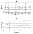
図4(A)は、或るマイクロフォン2で採取された音響振動の大きさを音圧―時間特性(第1モード)で出力したモニタの画面の例を示す。この波形例は、椅子に座った状態で右足の膝を速く伸ばしたときに右側の半月上(板)部分から「パキッ」と発せられた音響振動(衝撃音)の波形を示す。
FIG. 4A shows an example of a monitor screen in which the magnitude of acoustic vibration collected by a
図4(B)は、図4(A)に示されたマイクロフォン2で採取された音響振動の大きさを、音圧レベル―周波数特性(第2モード)で出力したモニタの画面の例を示す。
演算処理装置30は更に、全てのマイクロフォン2で採取された音響振動の位置、大きさを分布で出力する(第3の)モードを有する。このモードでは、演算処理された音響振動の位置、大きさが、全てのマイクロフォン2によって包囲された人体の部位(例えば、膝)の断面に対応する面を多数のセルによって分割したグリッド上に表示(断層画像表示)される。図5は、このモードにおけるモニタの画面の例を示す。図5に示される画面(出力結果)に表れるグリッドを構成する各セル(グリッドの目)が、人体の部位の断面に対応する面の各位置又は領域を示し、各セルの濃淡が音響振動の大きさ(Pa)を示している。
FIG. 4B shows an example of a monitor screen in which the magnitude of the acoustic vibration collected by the
The
マイクロフォン2で採取された音響振動に関する情報に基づいて、同音響振動の位置、大きさを図5の分布で示す手法は確立されていないと思われる。そこで、以下、マイクロフォン2で採取された音響振動に関する情報に基づいて、骨振動の力学的モデルと断層画像化の手法を用いて、同音響振動の位置、大きさを図5のグリッドに示す方法を説明する。
膝や肘などの可動部位が運動すると、振動的力が生ずる。この振動的力の伝達状態を図6を用いて説明する。すなわち、振動的力が生ずると質量m0を有する骨60が振動し、この骨60の振動は、質量m1及びバネ定数k1を有する、筋肉や脂肪などによって構成される柔軟組織61を介して、質量m3を有するスリーブ3に伝えられる。このスリーブ3と肘等の皮膚との間には、ばね定数k2を有する空洞62が構成され、スリーブ3は、ばね定数k10を有するベルト10、11により弾性支持されている。
Based on the information about the acoustic vibration collected by the
When movable parts such as knees and elbows move, vibrational forces are generated. The state of transmission of this vibrational force will be described with reference to FIG. That is, when a vibrational force is generated, the
骨60がゆっくり運動するときには、スリーブ3は、骨60とスリーブ3との間に介在している柔軟組織61と一体に運動し、骨60の前記運動に追随するので、スリーブ3には骨60が発する振動と異なる振動は起こらず、空洞62に音圧は生じない。
しかし、スリーブ3が柔軟組織61上で共振する周波数以上では、スリーブ3は骨60の振動に対して防振され、柔軟組織61と一体に運動しないので、すなわち、骨60の前記運動に追随しないので、スリーブ3に骨60の発する振動と異なった振動が発生する。その結果、この周波数領域では、骨60からの振動により、柔軟組織61が空洞62内の空気を圧縮、膨張させ、皮膚とスリーブ3との相対変位に比例した音圧が空洞62内に生じる。
When the
However, above the frequency at which the
そこで、診断に役立つ骨60の振動の周波数が前述した防振領域になるように、スリーブの質量m3、及び、皮膚との接触面積、すなわち、バネ定数k1を決める。空洞62の底面に相当する皮膚の面積は広いほうがスリーブ3に振動を抑制されず、皮膚に自由な振動を行なわせることができる。一方、空洞62の容積は小さいほうが内部に生ずる音圧が高くなるので、空洞62の形状としては、皮膚の振動中央部がスリーブ3やマイクロフォン2と接触しない程度の浅い円錐とすることが好ましい。
Therefore, the mass m 3 of the sleeve and the contact area with the skin, that is, the spring constant k 1 are determined so that the vibration frequency of the
実際の測定作業としては、まず、診断すべき人体の部位として想定される位置を含む断面を想定し、その断面と交差する身体の部位に複数のマイクロフォンを取り付け、各マイクロフォンより音響振動データを得る。
次に、前記人体部位の断面を、患者のサイズや人体の統計的データを参照して、複数のセル又は領域に切り分けて、グリッドを形成する。そして、グリッドの各セルについて、対応する人体部位の振動振幅を、計測された各音圧から逆算により求める。以上により図5に示される画面表示を作成することができる。
As an actual measurement operation, first, a cross section including a position assumed as a human body part to be diagnosed is assumed, a plurality of microphones are attached to a body part intersecting the cross section, and acoustic vibration data is obtained from each microphone. .
Next, the cross section of the human body part is divided into a plurality of cells or regions with reference to the patient size and the statistical data of the human body to form a grid. And about each cell of a grid, the vibration amplitude of a corresponding human body part is calculated | required by back calculation from each measured sound pressure. Thus, the screen display shown in FIG. 5 can be created.
なお、前記逆算には、人体の力学的なモデルにより、診断部位の各振動振幅と各音圧との間の伝達関数を用いる。有限要素法などを使って求めておく各伝達関数などは、診断部位とマイクロフォン2との間の距離や方向、組織の硬さなどにより決定される値である。
演算処理装置30は更に、前記演算処理した各音響振動の位置、大きさと、記憶手段(図示せず)に予め格納された、正常な対応人体部位から生ずる音響振動の位置、大きさに関するデータとを比較し、前記データから外れた各音響振動の位置、大きさを分布で出力する(第4の)モードを有する。このモードにおける分布の表示の仕方は、この実施形態では、図5に示される画面と同じである。
In the reverse calculation, a transfer function between each vibration amplitude and each sound pressure of the diagnostic part is used according to a dynamic model of the human body. Each transfer function obtained using the finite element method or the like is a value determined by the distance and direction between the diagnosis site and the
The
再び図1を参照すると、プリンタ50が第2出力装置として設けられている。このプリンタ50は、本実施形態では、第1出力装置40の指令入力装置(キーボード)に接続され、この指令入力装置の指令に従って、モニタの画面に表示される第1モード乃至第4モードの情報を、紙出力することができるようになっている。
Referring again to FIG. 1, a
次に、上述した構成の診断システム1の作動を、該診断システム1を膝に用いた場合を例にとって説明する。
診断システム1を使用するにあたっては、先ず、各マイクロフォン2の本体2aをスリーブ3のマイクロフォン取付穴8に嵌め、本体2aから延びる電気コード2bの近位端部をスリーブ3の切欠部6a又は6bで保持する。
次いで、ベルト10、11を各スリーブ3のベルト挿通穴4a、4b、5a、5bに夫々通し、各スリーブ3(マイクロフォン2の本体2a)が膝の適所(例えば、膝のある断面に沿って等間隔)に位置するように、各ベルト10、11を締結する。
この状態で膝を曲げ、或いは、伸ばすと、各マイクロフォン2が膝から発せられる音響を採取し、これを電気信号に変換してアンプ20に送信する。アンプ20は、送信された電気信号を増幅して演算処理装置30に送信する。演算処理装置30は、受信した電気信号に基づいて各マイクロフォン2で採取した音響の位置及び大きさを演算処理し、演算処理した各種の結果を記憶し、選択的に読み出し可能にする。
Next, the operation of the diagnostic system 1 having the above-described configuration will be described taking as an example the case where the diagnostic system 1 is used on the knee.
In using the diagnostic system 1, first, the
Next, the
When the knee is bent or stretched in this state, each
演算処理装置30で記録された各種演算結果は、第1出力装置40の指令入力装置を用いて、第1出力装置40のモニタ(CRT)に表示し、及び/又は、第2出力装置であるプリンタ50で紙出力させることができる。
本件診断システムの使用者、例えば、医師は、出力装置40、50の出力結果、例えば、図4(B)のスペクトル特性(第2モードでの出力結果)から、「パキ」音は0〜47.5Hzに集中した成分であることを知見し、これにより、例えば、以降の診断において、0〜47.5Hzに集中した成分からなる音響が生じたときには、たとえ実際に耳で直接聞くことができなかったときでも、「パキ」音が発せられていることを推測することができ、このような衝撃音である「パキ」音(0〜47.5Hzに集中した成分からなる音響)が生じたときには、関節病変の病態であることがわかっておれば、図4(B)のスペクトル特性が診断の一助となる。
Various arithmetic results recorded by the
A user of the present diagnosis system, for example, a doctor, determines that the “paki” sound is 0 to 47 from the output results of the
更に、図5に示す膝の音響振動の位置、大きさを示す分布(第3モードでの出力結果)から、例えば、医師は、右膝の内側寄り下方部分から大きな音響振動が生じたことを知見し、これにより、例えば、このような大きな音響振動が生じた当該部位に被診断者が問題を抱えていると推測することができる。
更にまた、前記第4モードでの出力結果によれば、正常な者との比較において、看者の異常(疾患)部位の位置、異常の大きさ(疾患の程度)それ自体が一目で分かる。
本発明は、上述した実施形態に限定されることなく以下のような種々の変更が可能である。
Furthermore, from the distribution (output result in the third mode) indicating the position and magnitude of the acoustic vibration of the knee shown in FIG. 5, for example, the doctor has confirmed that a large acoustic vibration has occurred from the lower part closer to the inside of the right knee. As a result, for example, it can be estimated that the person to be diagnosed has a problem at the site where such a large acoustic vibration has occurred.
Furthermore, according to the output result in the fourth mode, the position of the abnormal (disease) part of the observer and the magnitude of the abnormality (degree of disease) itself can be seen at a glance in comparison with a normal person.
The present invention is not limited to the above-described embodiments, and various modifications as described below are possible.
例えば、上述した実施形態では、スリーブ3の周壁の頂面部には一対の対向した切欠部6a、6bが形成されていたけれども、これらに代えて、スリーブ3の周壁の頂面部を半径方向に貫通する1つの切欠部を採用しても良い。
また、上述した実施形態では、保持部材を人体に取り付けるための取付手段は、スリーブ3を膝に取り付けるためのベルト10、11によって構成されていたけれども、取付手段は、保持部材(スリーブ3)を互いに間隔を隔てた所定位置に固定する面状部材で構成しても良い。被診断者の体格に応じて幾つかの種類の面状部材を用意しておくことによって、音響振動採取装置(マイクロフォン2)を容易、迅速に採取すべき生体音を発する部位の適所に位置決めすることができる。面状部材の端部同士の連結にあたっては、これらの端部を、例えば、ゴムによって連結しておいても良い(この場合、面状部材は全体として環状になる)。連結手段は、勿論、その他の既知の任意の手段、例えば、面状部材の一方の端部に設けられたホックと、他方の端部に設けられたフックとによって構成しても良い。
For example, in the above-described embodiment, the top surface portion of the peripheral wall of the
In the embodiment described above, the attaching means for attaching the holding member to the human body is constituted by the
更に、上述した実施形態では、プリンタ50は第1出力装置40の指令入力装置(キーボード)に接続されていたけれども、プリンタ50に第2指令入力装置を設け、この第2指令入力装置を演算処理装置30に直接接続することによって、第2指令入力装置によって選択、指示されたモードで演算処理装置30の演算処理結果を紙出力することができるようにしても良い。また、第1出力装置40を構成するモニタ(CRT)に代えて、オシロスコープを使用しても良いし、第1出力装置40自体を所謂ノート型パソコンによって構成しても良い。また、このノート型パソコンによって演算処理装置30及び第1出力装置40の両方を構成しても良い。
Further, in the above-described embodiment, the
更に、音響振動、特に、肘等の可動部位の音響振動の採取に当たっては、可動部位の移動速度、又は、加速度を検出するための加速度センサを用い、出力手段による音響振動の出力の際、検出された可動部位の加速度も出力するのが良い。また、音響振動、特に、肘等の可動部位の音響振動の採取に当たっては、可動部位の移動範囲、又は、折り曲げ角度を検出するための角度センサを用い、出力手段による音響振動の出力の際、検出された可動部位の折り曲げ角度も出力するのが良い。同様に、音響振動の採取に当たって、ロードセルのような圧力センサを用い、出力手段による音響振動の出力の際、音響振動検出の際に部位に加わった荷重又は圧力の大きさも出力するのが良い。これらを音響振動と一緒に出力することによって、診断者は、音響振動がどのような状況で採取されたものであるかを容易に理解することができ、このことは、より正確な診断に寄与する。 Furthermore, when collecting acoustic vibrations, in particular, acoustic vibrations of movable parts such as elbows, an acceleration sensor for detecting the moving speed or acceleration of the movable parts is used. It is also preferable to output the acceleration of the movable part. Further, when collecting acoustic vibrations, in particular, acoustic vibrations of movable parts such as elbows, the movement range of the movable part or an angle sensor for detecting a bending angle is used. It is also preferable to output the detected bending angle of the movable part. Similarly, when collecting acoustic vibrations, a pressure sensor such as a load cell may be used to output the magnitude of the load or pressure applied to the part during acoustic vibration detection when the acoustic vibration is output by the output means. By outputting these together with acoustic vibrations, the diagnostician can easily understand under what circumstances the acoustic vibrations were collected, which contributes to a more accurate diagnosis. To do.
更にまた、採取した音響振動のうち、生体から生じたものでないことが明らかな音響振動を除去するための既知のフィルタ手段を、音響振動採取装置と演算処理装置との間、上記実施形態では、マイクロフォン2の本体2aとアンプ20との間、或いは、アンプ20と演算処理装置30との間に、設けても良い。
Furthermore, among the collected acoustic vibrations, a known filter means for removing acoustic vibrations that are clearly not generated from a living body is used between the acoustic vibration sampling apparatus and the arithmetic processing unit, in the above embodiment, You may provide between the
上述した実施形態では、本発明による診断システムを膝等の折り曲げられる部位用の診断システムとして説明したけれども、本発明の診断システムは、人体の任意の部位、例えば、頭部内の診断システムとして用いることもできる。 In the above-described embodiment, the diagnosis system according to the present invention has been described as a diagnosis system for a part that can be bent such as a knee. You can also.
1 診断システム
2 マイクロフォン(音響振動採取装置)
3 スリーブ(保持部材)
10、11 ベルト(取付手段)
30 演算処理装置
40 第1出力装置(出力手段)
50 プリンタ(出力手段)
1
3 Sleeve (holding member)
10, 11 Belt (attachment means)
30
50 Printer (output means)
Claims (5)
該各音響振動採取装置を保持する保持部材と、
これらの保持部材を人体の部位を包囲するように取り付けるための取付手段と、
前記各音響振動採取装置からの前記電気信号に基づいて各音響振動の位置、大きさを演算処理する演算処理装置と、
該演算処理装置の演算処理結果を、前記音響振動採取装置によって包囲された人体の部位の断面に対応する面を分割したグリッド上に、音響振動の位置、大きさの分布で出力する出力手段とを有する、
診断システム。 At least two acoustic vibration collection devices for collecting acoustic vibrations from the human body and converting them into electrical signals;
A holding member for holding each acoustic vibration sampling device;
An attachment means for attaching these holding members so as to surround a part of the human body;
An arithmetic processing unit that calculates the position and magnitude of each acoustic vibration based on the electrical signal from each acoustic vibration sampling device;
An output means for outputting the calculation processing result of the calculation processing device in a position and size distribution of acoustic vibrations on a grid obtained by dividing a plane corresponding to a cross section of a part of a human body surrounded by the acoustic vibration sampling device; Having
Diagnostic system.
前記演算処理装置が、演算処理した各音響振動の位置、大きさと、前記記憶手段のデータとを比較し、前記データから外れた各音響振動の位置、大きさを演算処理し、
前記出力手段が、前記データから外れた各音響振動の位置、大きさの分布で出力する、請求項1記載の診断システム。 Storage means for storing data relating to the position and magnitude of the acoustic vibration generated from a normal human body part, connected to the arithmetic processing unit;
The arithmetic processing device, the position of each acoustic vibration processing, and size, compared with the data of the storage unit, the position of each acoustic vibration deviating from the data, and processing the size,
It said output means, the position of each acoustic vibration deviating from the data, and outputs the size distribution, the diagnostic system of claim 1, wherein.
前記出力手段が、前記センサの検出結果を出力する、請求項1または請求項2に記載の診断システム。 Acceleration sensor for detecting the acceleration of the moving part of the human body, angle sensor for detecting the movable range of the moving part of the human body, and pressure sensor for detecting the magnitude of the load applied to the part of the human body At least one of
The diagnostic system according to claim 1, wherein the output unit outputs a detection result of the sensor.
上端が開放したスリーブからなり、
該スリーブの周壁には少なくとも二対の第1貫通穴が形成され、各対の第1貫通穴は互いに対向して配置され、
前記スリーブの底壁の中央部には、前記音響振動採取装置が取り付けられる第2貫通孔が形成され、
前記スリーブの底壁の底面が、円錐面を構成するように、前記第2貫通孔から下方に向って半径方向外方に傾斜する、
請求項1乃至請求項3のいずれか一項に記載の診断システム。 The holding member is configured to be attached to a human body via belt means,
It consists of a sleeve with an open top,
At least two pairs of first through holes are formed in the peripheral wall of the sleeve, and the first through holes of each pair are arranged to face each other,
In the central portion of the bottom wall of the sleeve, a second through hole to which the acoustic vibration sampling device is attached is formed,
A bottom surface of the bottom wall of the sleeve is inclined radially outward from the second through-hole so as to form a conical surface;
The diagnostic system according to any one of claims 1 to 3 .
Priority Applications (1)
| Application Number | Priority Date | Filing Date | Title |
|---|---|---|---|
| JP2004119886A JP4411384B2 (en) | 2004-04-15 | 2004-04-15 | Diagnostic system |
Applications Claiming Priority (1)
| Application Number | Priority Date | Filing Date | Title |
|---|---|---|---|
| JP2004119886A JP4411384B2 (en) | 2004-04-15 | 2004-04-15 | Diagnostic system |
Publications (2)
| Publication Number | Publication Date |
|---|---|
| JP2005296482A JP2005296482A (en) | 2005-10-27 |
| JP4411384B2 true JP4411384B2 (en) | 2010-02-10 |
Family
ID=35328732
Family Applications (1)
| Application Number | Title | Priority Date | Filing Date |
|---|---|---|---|
| JP2004119886A Expired - Fee Related JP4411384B2 (en) | 2004-04-15 | 2004-04-15 | Diagnostic system |
Country Status (1)
| Country | Link |
|---|---|
| JP (1) | JP4411384B2 (en) |
Families Citing this family (6)
| Publication number | Priority date | Publication date | Assignee | Title |
|---|---|---|---|---|
| CN102112049B (en) * | 2008-05-29 | 2014-10-22 | 伊塔马医疗有限公司 | Method and apparatus for examining subjects for particular physiological conditions utilizing acoustic information |
| US8444564B2 (en) * | 2009-02-02 | 2013-05-21 | Jointvue, Llc | Noninvasive diagnostic system |
| WO2011096419A1 (en) * | 2010-02-05 | 2011-08-11 | 学校法人 日本大学 | Bio-acoustic sensor and diagnostic system using the bio-acoustic sensor |
| JP6307462B2 (en) * | 2015-03-13 | 2018-04-04 | 富士フイルム株式会社 | Joint sound measurement system |
| JP6449753B2 (en) * | 2015-11-05 | 2019-01-09 | 国立大学法人佐賀大学 | Joint inflammation detection device |
| JP7132816B2 (en) * | 2018-10-10 | 2022-09-07 | 大和ハウス工業株式会社 | Joint condition determination system |
-
2004
- 2004-04-15 JP JP2004119886A patent/JP4411384B2/en not_active Expired - Fee Related
Also Published As
| Publication number | Publication date |
|---|---|
| JP2005296482A (en) | 2005-10-27 |
Similar Documents
| Publication | Publication Date | Title |
|---|---|---|
| KR101327603B1 (en) | Weighted bioacoustic sensor and method of using same | |
| JP5763342B2 (en) | Adhesive patch for measuring acoustic signals | |
| JP5808909B2 (en) | Passive monitoring sensor system using mattress | |
| US10039520B2 (en) | Detection of coronary artery disease using an electronic stethoscope | |
| KR101327694B1 (en) | Cantilevered bioacoustic sensor and method using same | |
| JP6731676B2 (en) | Biological information detector | |
| JP5873875B2 (en) | Signal processing apparatus, signal processing system, and signal processing method | |
| JP2021519622A (en) | Systems and methods for elastography and viscoelastography imaging | |
| JP2019521756A (en) | Method for detecting occlusion in a fluid flow vessel | |
| US9320489B1 (en) | Apparatus for detection of cardiac acoustic signals | |
| EP3678551B1 (en) | Electronic stethoscope with enhanced features | |
| US6726635B1 (en) | Cardiac impulse detector | |
| Courteville et al. | MMG measurement: A high-sensitivity microphone-based sensor for clinical use | |
| Zanartu et al. | Air-borne and tissue-borne sensitivities of bioacoustic sensors used on the skin surface | |
| JP4411384B2 (en) | Diagnostic system | |
| JP2004305268A (en) | Cardiac sound detector | |
| Watrous et al. | Methods and results in characterizing electronic stethoscopes | |
| CN109199353A (en) | Electronic blood pressure monitor, blood pressure measuring method and electronic auscultation device | |
| JPH04317637A (en) | Bioacoustic converter | |
| JP2019010436A (en) | Biological sensor and signal acquisition method of biological sensor | |
| WO1998046138A1 (en) | Cardiovascular monitor | |
| JP2792386B2 (en) | Biological information processing device | |
| JP2002058653A (en) | Detecting unit for organismic signals | |
| US20090326418A1 (en) | Microphone matrix for recording body sounds | |
| Lakshmi et al. | Effect of Contact Force on Foetal Heart Sound Recordings |
Legal Events
| Date | Code | Title | Description |
|---|---|---|---|
| A621 | Written request for application examination |
Free format text: JAPANESE INTERMEDIATE CODE: A621 Effective date: 20051228 |
|
| A131 | Notification of reasons for refusal |
Free format text: JAPANESE INTERMEDIATE CODE: A131 Effective date: 20081104 |
|
| A521 | Written amendment |
Free format text: JAPANESE INTERMEDIATE CODE: A523 Effective date: 20090105 |
|
| A131 | Notification of reasons for refusal |
Free format text: JAPANESE INTERMEDIATE CODE: A131 Effective date: 20090706 |
|
| A521 | Written amendment |
Free format text: JAPANESE INTERMEDIATE CODE: A523 Effective date: 20090904 |
|
| TRDD | Decision of grant or rejection written | ||
| A01 | Written decision to grant a patent or to grant a registration (utility model) |
Free format text: JAPANESE INTERMEDIATE CODE: A01 Effective date: 20090928 |
|
| A01 | Written decision to grant a patent or to grant a registration (utility model) |
Free format text: JAPANESE INTERMEDIATE CODE: A01 |
|
| A61 | First payment of annual fees (during grant procedure) |
Free format text: JAPANESE INTERMEDIATE CODE: A61 Effective date: 20091007 |
|
| FPAY | Renewal fee payment (event date is renewal date of database) |
Free format text: PAYMENT UNTIL: 20121127 Year of fee payment: 3 |
|
| R150 | Certificate of patent or registration of utility model |
Free format text: JAPANESE INTERMEDIATE CODE: R150 |
|
| LAPS | Cancellation because of no payment of annual fees |