JP4407985B2 - Image processing method and apparatus, and storage medium - Google Patents
Image processing method and apparatus, and storage medium Download PDFInfo
- Publication number
- JP4407985B2 JP4407985B2 JP24823799A JP24823799A JP4407985B2 JP 4407985 B2 JP4407985 B2 JP 4407985B2 JP 24823799 A JP24823799 A JP 24823799A JP 24823799 A JP24823799 A JP 24823799A JP 4407985 B2 JP4407985 B2 JP 4407985B2
- Authority
- JP
- Japan
- Prior art keywords
- block
- group
- image processing
- frequently occurring
- motion amount
- Prior art date
- Legal status (The legal status is an assumption and is not a legal conclusion. Google has not performed a legal analysis and makes no representation as to the accuracy of the status listed.)
- Expired - Fee Related
Links
Images


Classifications
-
- G—PHYSICS
- G06—COMPUTING; CALCULATING OR COUNTING
- G06T—IMAGE DATA PROCESSING OR GENERATION, IN GENERAL
- G06T9/00—Image coding
- G06T9/20—Contour coding, e.g. using detection of edges
-
- G—PHYSICS
- G06—COMPUTING; CALCULATING OR COUNTING
- G06T—IMAGE DATA PROCESSING OR GENERATION, IN GENERAL
- G06T9/00—Image coding
- G06T9/001—Model-based coding, e.g. wire frame
-
- H—ELECTRICITY
- H04—ELECTRIC COMMUNICATION TECHNIQUE
- H04N—PICTORIAL COMMUNICATION, e.g. TELEVISION
- H04N19/00—Methods or arrangements for coding, decoding, compressing or decompressing digital video signals
- H04N19/50—Methods or arrangements for coding, decoding, compressing or decompressing digital video signals using predictive coding
- H04N19/503—Methods or arrangements for coding, decoding, compressing or decompressing digital video signals using predictive coding involving temporal prediction
-
- H—ELECTRICITY
- H04—ELECTRIC COMMUNICATION TECHNIQUE
- H04N—PICTORIAL COMMUNICATION, e.g. TELEVISION
- H04N19/00—Methods or arrangements for coding, decoding, compressing or decompressing digital video signals
- H04N19/60—Methods or arrangements for coding, decoding, compressing or decompressing digital video signals using transform coding
- H04N19/61—Methods or arrangements for coding, decoding, compressing or decompressing digital video signals using transform coding in combination with predictive coding
Landscapes
- Engineering & Computer Science (AREA)
- Multimedia (AREA)
- Physics & Mathematics (AREA)
- General Physics & Mathematics (AREA)
- Theoretical Computer Science (AREA)
- Signal Processing (AREA)
- Image Analysis (AREA)
- Compression Or Coding Systems Of Tv Signals (AREA)
Abstract
Description
【0001】
【発明の属する技術分野】
本発明は、画像処理方法及び装置並びに記憶媒体に関し、より具体的には、動画像におけるオブジェクトを抽出する画像処理方法及び装置、並びに、その方法を実行するプログラム・ソフトウエアを記憶する記憶媒体に関する。
【0002】
【従来の技術】
近年、動画像をオブジェクトという構成要素の合成からなると把握し、そのオブジェクトを単位として圧縮符号化する方式が、検討され、現在、MPEG4として標準化作業が進行中である。オブジェクトは任意の形状を取り得るので、形状情報を表すシェイプと呼ばれるデータと画像の内容を表すテクスチャと呼ばれるデータの組合わせで表現される。
【0003】
オブジェクトの生成方法として、スタジオセット等を用いたクロマキー分離法、コンピュータ・グラフィックス(CG)による目的のオブジェクトを生成する方法、及び自然画から抽出する方法などが知られている。
【0004】
クロマキー法は、スタジオにブルーバックと呼ばれる均一な青色の背景を用意し、撮影画像からブルーの部分を切り取ることにより、対象のオブジェクトを抽出する方法である。
【0005】
コンピュータ・グラフィックスでは、初めから任意形状の画像を生成できるので、特に抽出処理を考える必要はない。また、アニメーション画像の場合は、1つ1つのセル画を各オブジェクトと見なせば、CGと同様に処理できる。
【0006】
自然画からオブジェクトを抽出する場合、最初のフレームで抽出対象の輪郭をユーザが大まかに指定した輪郭を画像処理により対象物に収束させることで、対象物の正確な輪郭を抽出する。2枚目以降のフレームでは、前のフレームでの輪郭抽出結果を初期輪郭として対象物を追跡する。輪郭追跡の代表的な方法として、スネークスと呼ばれる動的輪郭モデルのエネルギー最小化がよく知られている(例えば、Michael Kass, Andrew Witkin, and Demetri TerzoPoulos, ”Snakes:Activc Contour Mode1s”, International Jounal of Computer Vision, Vol.1, No.3,pp.321−331, 1988)。
【0007】
スネークスは、輪郭線が抽出されたときに最小となるエネルギー関数を定義し、適当な初期値からその極小解を反復計算により求めるものである。エネルギー関数は、エッジ点を通る制約の外部エネルギーと滑らかさの制約である内部エネルギーの線形和で定義される。
【0008】
【発明が解決しようとする課題】
これらの抽出方法は、いずれも困難な問題点を含んでいる。すなわち、クロマキー法は、背景色が均一である必要があり、精度の高い抽出を目指すと、大掛かりなスタジオセットが必要となる。また、オブジェクト対象が背景色を含んでいる場合に、対象を正しく抽出できないので、対象の色が制約される。
【0009】
コンピュータ・グラフィックス及びアニメーションでは、抽出処理は必要ないが、ビデオカメラで撮影したような自然画に適用できない致命的な欠点を有している。
【0010】
自然画からオブジェクトを抽出する方法は、画像内容に対する制約が低く、汎用性が高いという利点がある反面、初期輪郭をある程度正確に指定する必要があるという欠点がある。これは、動的輪郭モデルの極小解が初期輪郭の影響を大きく受けることによる。第2フレーム以降の初期輪郭は、前フレームの輪郭抽出結果を初期値として利用すればよいが、最初のフレームだけは、ユーザがグラフィカル・ユーザ・インターフェース(GUI)等によりマニュアル操作で設定する必要がある。マニュアルによる初期輪郭設定では、マウスを使った操作が一般的であるが、操作性が悪く、再現性のある初期輪郭設定が困難である。輪郭の形状が複雑になるほど、ユーザの負担が大きくなる。
【0011】
本発明は、より簡易な操作で、より正確な輪郭線を抽出できる画像処理方法及び装置並びに記憶媒体を提示することを目的とする。
【0012】
【課題を解決するための手段】
本発明に係る画像処理方法は、画像処理装置が実行する画像処理方法であって、画像データを複数のブロックに分割するブロック分割ステップと、時間的に離れた画像データとの間で、当該ブロック単位で動き量を算出する動き量算出ステップと、当該動き量算出ステップで算出した動き量の発生頻度に従い、当該画像データの各ブロックを、抽出対象に対応する抽出対象ブロック・グループ、当該抽出対象の背景に対応する背景ブロック・グループ及び当該抽出対象と当該背景の境界となる境界ブロック・グループの何れかに分類するブロック分類ステップと、当該ブロック分類ステップの分類結果に従い、当該境界ブロック内に当該抽出対象の初期輪郭を生成する初期輪郭生成ステップと、当該初期輪郭生成ステップで生成された当該初期輪郭に基づいて当該抽出対象の輪郭を決定する輪郭決定ステップとを具備することを特徴とする。
【0013】
本発明に係る画像処理装置は、画像データを複数のブロックに分割するブロック分割手段と、時間的に離れた画像データとの間で、当該ブロック単位で動き量を算出する動き量算出手段と、当該動き量算出手段で算出した動き量の発生頻度に従い、当該画像データの各ブロックを、抽出対象に対応する抽出対象ブロック・グループ、当該抽出対象の背景に対応する背景ブロック・グループ及び当該抽出対象と当該背景の境界となる境界ブロック・グループの何れかに分類するブロック分類手段と、当該ブロック分類手段の分類結果に従い、当該境界ブロック内に当該抽出対象の初期輪郭を生成する初期輪郭生成手段と、当該初期輪郭生成手段で生成された当該初期輪郭に基づいて当該抽出対象の輪郭を決定する輪郭決定手段とを具備することを特徴とする。
【0014】
本発明に係る記憶媒体には、上述の画像処理方法を実行するプログラム・ソフトウエアが格納される。
【0015】
【実施例】
以下、図面を参照して、本発明の実施例を詳細に説明する。
【0016】
図1は、本発明の一実施例の概略構成ブロック図を示す。10は、ビデオカメラ及び画像再生装置などからなり、動画像をメモリ12に入力する画像入力装置である。メモリ12は、画像入力装置10から入力された画像データを数フレーム分、一時記憶する。動き量検出回路14は、メモリ12に一時記憶された複数のフレームの画像データから、所望のフレーム上での各部の動き量を検出する。境界設定回路16は、動き量検出回路14の検出結果に従い、背景部分とオブジェクト部分の境界を求め、初期輪郭設定回路18は、境界設定回路16で求めた境界に従い閉じた初期輪郭を設定する。輪郭抽出回路20は、初期輪郭を実際のオブジェクトの輪郭に収束させ、その収束結果をメモリ12に格納する。メモリ12は、輪郭抽出回路20で得られた輪郭で囲まれる閉領域の画像を目的のオブジェクト部分として画像出力装置22に出力する。輪郭は次のフレームの初期輪郭として、フレームの更新のタイミングで初期輪郭設定回路18に設定される。
【0017】
図2は、本実施例の動作フローチャートを示す。スタートフレームとエンドフレームを決定する(S1,S2)。これらは抽出したいオブジェクトを含む期間を規定するものであり、例えば、図3に示すように、画面上に一連のフレームを同時に表示するグラフィカル・ユーザ・インターフェースを用いることで、容易に設定できる。次に、抽出対象を含む先頭フレームをターゲットフレームとして設定する(S3)。通常は、スタートフレームがターゲットフレームとなる。
【0018】
ターゲットフレームを図4に示すように、水平及び垂直方向でブロック化する。ブロックサイズは任意であるが、例えば画像サイズを720×480画素とし、1つのブロックのサイズを16×16画素であるとすると、ブロック数は(720/16)×(480/16)=1350となる。RGB3つのプレーンで処理する場合、1フレームの全ブロック数は1350×3=4050となる。輝度成分と色差成分が4:2:2のフォーマットの場合、1350×2=2700となる。輝度信号だけで処理する場合は、ブロック数は1350でよい。
【0019】
サンプルフレームを設定する(S5)。通常はターゲットフレームと時間的に連続したフレームを最初のサンプルフレームとする。図3に示す動画像例では、サンプルフレームは、図4に示すターゲットフレームに対して、図5に示すようにオブジェクトが右方向に動いたものになる。動き量検出回路14が、サンプルフレームにおいて各ブロック単位で動きベクトルを検出する(S6)。
【0020】
ターゲットの動きが2次元のアフィン変換に従うと仮定できる場合、ターゲットフレームの位置(x,y)とサンプルフレーム上の位置(X,Y)との間には、下記式が成立する。すなわち、
X=a×x+b×y+c (1)
Y=d×x+e×y+f (2)
動きが平行移動のみと仮定できる場合には、簡略化でき、
X=x+c (3)
Y=y+f (4)
となる。サーチ範囲を上式で動かしながら差分二乗和を求め、サーチ範囲内でそれが最小であった位置をマッチングの取れた場所とし、動きベクトル値を記憶する。
【0021】
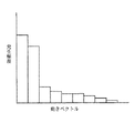
フレーム内の全てのブロックに対し動きベクトル値が求まったら、動きベクトルを分類する(S7)。実質的に同じ動きベクトル値を持つものを同じグループとして登録する。サーチ範囲が水平及び垂直に+/−16画素で、1画素精度の平行移動とした場合、発生し得る動きベクトルの種類は、33×33=1089パターンとなる。図6は、そのように分類されたブロックのヒストグラム例を示す。図6の横軸は動きベクトル、縦軸は発生頻度又はブロック数をそれぞれ示す。但し、横軸方向には、発生頻度の多い順に配列してある。
【0022】
画面全体で有意な動きが検出できなかった場合(S8)、サンプルフレームを変更して(S5)、再度、動きベクトルを算出し(S6)、動きベクトルを分類する(S7)。
【0023】
画面全体で有意な動きを検出できたら(S8)、各ブロックを、背景のブロック、オブジェクト(前景)のブロック、及び背景とオブジェクトの両方にまたがった境界のブロックの3グループに分類する(S9)。このグループ化の方法は後ほど詳細に説明する。例えば、図7に例示するように、前景ブロックを境界ブロックが囲み、その外側に背景ブロックが位置するような関係になる。ブロック化の設定位置によっては、図8に示すように、境界ブロックが存在せずに、背景ブロックとオブジェクトブロックが接している場合もありうる。このような状態は、ブロック内のほとんどの部分が背景で、わずかにオブジェクト部分が含まれている場合、又は、その逆に、ブロック内のほとんどの部分がオブジェクトで、わずかに背景部分が含まれている場合などに起こりうる。
【0024】
境界ブロックと判定されたブロックは、そのブロック内に輪郭線を含むので、そのブロック内に初期輪郭を構成する点を設定する(S10)。背景ブロックとオブジェクトブロックが接している場合、その接している部分に初期輪郭を構成する点を設定する(S11)。これらの点を順次つないで閉曲線を作り、これを初期輪郭とする(S12)。
【0025】
ブロック内及びブロック境界上に設定する点の数は任意であるが、隣接ブロックの点との連続性を考慮すべきである。図9は、初期輪郭の設定例を示す。背景ブロックとオブジェクトブロックの接している部分では、境界線上を初期輪郭とし、境界ブロックでは、オブジェクト内部と外部がほぼ等しく分かれるように初期輪郭を設定する。
【0026】
このように設定された初期輪郭をオブジェクトの輪郭に収束させる(S13)。例えば、スネークスと呼ばれる処理を実行する。図8は、初期輪郭がオブジェクトの輪郭に合うように収束していく様子を示す。このようにして輪郭線が決定すると(S14)、第1フレームのオブジェクト抽出処理が終わる。この抽出結果を基に、次フレームの初期輪郭を設定する(S15)。最も単純な方法では、前フレームの輪郭線抽出結果を新たな初期輪郭に設定する。
【0027】
ターゲットフレームを更新し(S16)、S132〜S16を再度、実行する。ターゲットフレームがエンドフレームに到達して、S13〜S16の処理を終了すると(S17)、全てのフレームに対するオブジェクト抽出処理が終了したことになるので、一連の処理を終える。
【0028】
図11は、ブロックのグループ化(S9)の詳細なフローチャートを示す。もちろん、図11は一例であり、この種のグループ化には幾つかの方法が考えられる。
【0029】
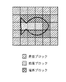
1番目に発生頻度の高いブロックを背景ブロックとし(S21,S22)、2番目に発生頻度の高いブロックを前景ブロックとし(S23,S24)、これら以外のブロックを境界ブロックする(S25)。全てのブロックをこの基準で分類する(S26)。図6に示す動きベクトルの分類例では、図12に示すように、背景ブロック、前景ブロック及び境界ブロックにグループ化される。
【0030】
ブロックの発生頻度が高いということは、まとまった動きのあることを示しており、一番広い領域が背景と考えられる。次にまとまった動きのある領域がオブジェクトと考えられるので、それを前景ブロックとしている。まとまった動きが2つしかない場合、3番目以降のブロックの発生頻度は極端に少なくなる。これらは、対応する部分がうまく見つからなかったブロックである。ブロック内に背景部分とオブジェクトの部分の両方を含んでいる場合、同様のブロックをサンプルフレームのサーチ範囲から見つけることができないので、結果としてさまざまなベクトル値を持つことになる。従って、これらのブロックを境界ブロックと設定すればよい。
【0031】
背景に分類されるブロックと前景に分類されるブロックを、動きベクトルに対するブロックの発生頻度で決定したが、位置情報を考慮し、画面端に多く接しているブロックを背景としてもよい。
【0032】
図13は、ブロックのグループ化(S9)の別の詳細なフローチャートを示す。1番目に発生頻度の高いブロックを背景ブロックと設定する(S31,S32)。1番目に発生頻度の高いブロックではないが、1番目に発生頻度の高いブロック(背景ブロック)に隣接しているブロックを、境界ブロックと設定する(S33,S35)。背景ブロック及び境界ブロックのどちらでもないブロックを前景ブロックと設定する(S33,S34)。以上の処理を全てのブロックについて実行する(S36)。
【0033】
この方法は、背景ブロックに隣接しているブロックを境界ブロックするものであるが、逆に、前景ブロックを求め、それに隣接するブロックを境界ブロックとしても、類似した又は同様の結果が得られる。
【0034】
また、発生頻度が3番目以降のブロックに対しベクトルの類似度を求め、1番目に発生頻度の高いブロックと2番目に発生頻度の高いブロックのいずれか近い方に分類する方法もある。図14は、そのフローチャートを示す。
【0035】
先ず、1番目に発生頻度の高いブロックを背景ブロックと設定する(S41,S42)。2番目に発生頻度の高いブロックを、前景ブロックと設定する(S43,S44)。3番目以降に発生頻度の高いブロックの場合(S43)、背景ブロック及び前景ブロックとの動きベクトルの類似度を計算する。これは、該当ブロックの動きベクトルが、1番目に発生頻度の高いグループの動きベクトル値と、2番目に発生頻度の高いグループの動きベクトル値のどちらに近いかを求めるものである。例えば、各動きベクトルの内積により動きベクトル間の距離を求めればよい。この計算結果を基に、1番目に発生頻度の高いグループの動きベクトルに近いければ(S46)、暫定的に背景ブロック(暫定背景ブロック)と設定し(S47)、2番目に発生頻度の高いグループの動きベクトルに近ければ(S46)、暫定的に前景ブロック(暫定前景ブロック)と設定する(S48)。以上の処理を全てのブロックについて実行する(S49)。
【0036】
図14に示す方法による暫定的な分類結果の例を図15に示す。1番目に発生頻度の高いブロックと2番目に発生頻度の高いブロックの、互いに隣接するブロック(図14による暫定背景ブロック及び暫定前景ブロック)が、境界ブロックとなる。両者の内で、1番目に発生頻度の高いブロックを境界ブロックとするか、2番目に発生頻度の高いブロックを境界ブロックとするかは任意である。
【0037】
図16は、図14による結果を引き継いで、最終的に境界ブロックを決定する方法のフローチャートを示す。注目ブロックが暫定背景ブロックかどうかを判定し(S51)、暫定波形ブロックである場合には(S51)、前景ブロックに隣接しているか否かを判定する(S52)。前景ブロックに隣接していれば(S52)、このブロックを境界ブロックとし(S53)、隣接していなければ(S52)、このブロックを背景ブロックとする(S54)。暫定前景ブロックに対しても同様に(S55)、背景ブロックに隣接していれば(S56)、境界ブロックと設定し(S57)、そうでなければ前景ブロックと設定する(S58)。暫定ブロック以外のブロックはそのままとする。以上の処理を全てのブロックについて実行する(S59)。
【0038】
図15に示す例を図16に示す方法で最終的に分類した結果を図17に示す。
【0039】
初期輪郭設定の精度を更に向上させる第2実施例を説明する。図18は、第2の実施例の特徴部分の処理フローチャートを示す。図18に示すフローは、図2のS5〜S8の部分を代替する。
【0040】
図2のS5〜S8と同様に、先ず、サンプルフレームを設定し、全ブロックについて動きベクトルを算出及び分類する(S61〜64)。各ブロックが発生頻度に関してどのブロック・グループに属するかを調べ(S65,S66)、2番目に発生頻度の高いブロックであって1番目に発生頻度の高いブロックに隣接するブロック(S66,S67)と、3番目以降に発生頻度の高いブロック(S66)とを、再分割可能かどうかを調べ(S68)、可能であれば(S68)、再分割する(S69)。ブロックサイズが16×16の場合、例えば4つの8×8ブロックに分割する。
【0041】
ブロックを再分割した後で(S69)、再び、動きベクトルの算出及び分類を全ブロックについて実行する(S62〜S64)。2番目に発生頻度の高いブロックであって1番目に発生頻度の高いブロックに隣接するブロック(S66,S67)と、3番目以降に発生頻度の高いブロック(S66)とがあり、それが再分割可能である限り(S68)、ブロックを再分割して、以上を繰り返す。
【0042】
このようにブロックを再帰的に分割していくことにより、境界ブロックとなる部分を絞り込んでいくことができる。
【0043】
これ以上のブロック分割が不可能と判断された場合(S68)、ブロック(再分割した場合には、分割後のブロック)のグループ属性を保持したまま、次のブロックを同様に処理する(S65〜S68)。
【0044】
再分割されたブロックも含め、フレーム内での全てのブロックの処理が終わると(S70)、サンプルフレームを変更し(S61)、同様の処理を繰り返す。全てのサンプルフレームに対する処理が終了すると(S71)、このルーチンを終える。以後は、図2のS9以降と同じ処理を実行する。
【0045】
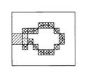
図19は、図18による処理結果例である。3番目以降に発生頻度の高いブロックを再分割すると共に、2番目に発生頻度の高いブロックであって、1番目に発生頻度の高いブロックに隣接するブロックも再分割している。再分割及び再分類が終った後、オブジェクト判定により、1番目に発生頻度の高いブロックを背景ブロック、2番目に発生頻度の高いブロックを前景ブロック、それ以外を境界ブロックと設定している。
【0046】
図20は、図19に示す例で初期輪郭線設定のためのブロックのみの表示する図である。図21は、図20に示す表示例から得られた初期輪郭を示す。第1実施例における初期輪郭(図9)に比べて、精度の高い結果が得られることがわかる。図22は、図21に示す初期輪郭がオブジェクトの輪郭に収束する様子を示す。
【0047】
【発明の効果】
以上の説明から容易に理解できるように、本発明によれば、動画のオブジェクト抽出を行う際の先頭フレームの初期輪郭を自動的に高精度に設定できる。これにより、ユーザの負担が大幅に軽減される。初期輪郭を自動設定するので、再現性のある初期輪郭を得ることも可能となる。
【図面の簡単な説明】
【図1】 本発明の第1実施例の概略構成ブロック図である。
【図2】 第1実施例の全体処理のフローチャートである。
【図3】 スタートフレームとエンドフレームの設定を説明する模式図である。
【図4】 ターゲットフレームのブロック化例である。
【図5】 サンプルフレームの画像例である。
【図6】 動きベクトルに関して分類されたブロックのヒストグラム例である。
【図7】 分類されたブロック例である。
【図8】 別のブロック分類例である。
【図9】 第1実施例による初期輪郭例である。
【図10】 第1実施例による輪郭線の収束の模式図である。
【図11】 ブロックのオブジェクト判定のフローチャートである。
【図12】 ブロック・グループの配属例である。
【図13】 オブジェクト判定の別のフローチャートである。
【図14】 暫定ブロックを設定するオブジェクト判定法のフローチャートである。
【図15】 図14による暫定的なグループ化の結果例である。
【図16】 暫定ブロックを最終的に決定する処理のフローチャートである。
【図17】 図16による処理結果例である。
【図18】 本発明の第2実施例の特徴部分の処理フローチャートである。
【図19】 ブロック再分割の模式図である。
【図20】 第2実施例における初期輪郭のブロック位置を例示する模式図である。
【図21】 第2実施例での初期輪郭例である。
【図22】 第2実施例における輪郭線の収束する様子の模式図である。
【符号の説明】
10:画像入力装置
12:メモリ
14:動き量検出回路
16:境界設定回路
18:初期輪郭設定回路
20:輪郭抽出回路
22:画像出力装置[0001]
BACKGROUND OF THE INVENTION
The present invention relates to an image processing method and apparatus, and a storage medium. More specifically, the present invention relates to an image processing method and apparatus that extracts an object in a moving image, and a storage medium that stores program software for executing the method. .
[0002]
[Prior art]
In recent years, a method of comprehending that a moving image is composed of components called objects and compressing and encoding the object as a unit has been studied, and standardization work is currently in progress as MPEG4. Since an object can take an arbitrary shape, it is represented by a combination of data called a shape representing shape information and data called a texture representing the contents of an image.
[0003]
As an object generation method, a chroma key separation method using a studio set or the like, a method of generating a target object by computer graphics (CG), a method of extracting from a natural image, and the like are known.
[0004]
The chroma key method is a method of extracting a target object by preparing a uniform blue background called a blue background in a studio and cutting out a blue portion from a photographed image.
[0005]
In computer graphics, since an image having an arbitrary shape can be generated from the beginning, there is no need to consider extraction processing. In the case of an animation image, if each cell image is regarded as each object, it can be processed in the same way as CG.
[0006]
When an object is extracted from a natural image, an accurate outline of the object is extracted by converging the outline in which the user roughly specifies the outline to be extracted in the first frame to the object by image processing. In the second and subsequent frames, the object is tracked using the contour extraction result in the previous frame as the initial contour. As a typical method of contour tracking, energy minimization of an active contour model called snakes is well known (for example, Michael Kass, Andrew Witkin, and Demetri TerzoPoulos, “Snakes: Active Contour Model Modes, Inf. Computer Vision, Vol.1, No.3, pp.321-331, 1988).
[0007]
Snakes define an energy function that becomes the minimum when a contour line is extracted, and obtain a minimal solution from an appropriate initial value by iterative calculation. The energy function is defined as a linear sum of the external energy of the constraint passing through the edge point and the internal energy of the smoothness constraint.
[0008]
[Problems to be solved by the invention]
Each of these extraction methods has a difficult problem. In other words, the chroma key method needs to have a uniform background color, and a large studio set is required for accurate extraction. In addition, when the object target includes a background color, the target cannot be correctly extracted, so the target color is restricted.
[0009]
Computer graphics and animation do not require extraction processing, but have fatal drawbacks that cannot be applied to natural images such as those shot with a video camera.
[0010]
The method of extracting an object from a natural image has the advantage that the restriction on the image content is low and the versatility is high, but there is a drawback that it is necessary to specify the initial contour to some extent accurately. This is because the minimal solution of the active contour model is greatly affected by the initial contour. For the initial contour after the second frame, the contour extraction result of the previous frame may be used as an initial value. However, only the first frame needs to be set manually by the user through a graphical user interface (GUI) or the like. is there. In manual initial contour setting, an operation using a mouse is common, but the operability is poor and it is difficult to set an initial contour with reproducibility. The more complicated the contour shape, the greater the burden on the user.
[0011]
An object of the present invention is to present an image processing method and apparatus and a storage medium that can extract a more accurate contour line with a simpler operation.
[0012]
[Means for Solving the Problems]
An image processing method according to the present invention is an image processing method executed by an image processing apparatus, wherein the block is divided between a block dividing step of dividing image data into a plurality of blocks and image data separated in time. A motion amount calculation step for calculating a motion amount in units, and an extraction target block / group corresponding to the extraction target, the extraction target block / group according to the motion frequency occurrence frequency calculated in the motion amount calculation step, and the extraction target a block classification step of classifying the one of the background block group and the extracted object and boundary block groups at the boundary of the background corresponding to the background of, in accordance with the classification result of the block classification step, the to the boundary block An initial contour generation step for generating an initial contour to be extracted, and the initial contour generated in the initial contour generation step. Characterized by comprising a contour determining step of determining the contour of the extracted object based on the contour.
[0013]
An image processing apparatus according to the present invention includes: a block dividing unit that divides image data into a plurality of blocks; and a motion amount calculating unit that calculates a motion amount in units of the blocks between image data separated in time. According to the frequency of occurrence of the motion amount calculated by the motion amount calculation means, each block of the image data is extracted as an extraction target block / group corresponding to the extraction target, a background block / group corresponding to the background of the extraction target, and the extraction target And a block classification unit that classifies the boundary block / group as a boundary of the background, and an initial contour generation unit that generates an initial contour of the extraction target in the boundary block according to the classification result of the block classification unit; A contour determining unit that determines a contour of the extraction target based on the initial contour generated by the initial contour generating unit. And features.
[0014]
The storage medium according to the present invention stores program software for executing the above-described image processing method.
[0015]
【Example】
Hereinafter, embodiments of the present invention will be described in detail with reference to the drawings.
[0016]
FIG. 1 shows a schematic block diagram of an embodiment of the present invention.
[0017]
FIG. 2 shows an operation flowchart of this embodiment. A start frame and an end frame are determined (S1, S2). These define the period including the object to be extracted. For example, as shown in FIG. 3, it can be easily set by using a graphical user interface that simultaneously displays a series of frames on the screen. Next, the first frame including the extraction target is set as a target frame (S3). Usually, the start frame is the target frame.
[0018]
The target frame is blocked in the horizontal and vertical directions as shown in FIG. Although the block size is arbitrary, for example, if the image size is 720 × 480 pixels and the size of one block is 16 × 16 pixels, the number of blocks is (720/16) × (480/16) = 1350. Become. When processing with three RGB planes, the total number of blocks in one frame is 1350 × 3 = 4050. When the luminance component and the color difference component are in a 4: 2: 2 format, 1350 × 2 = 2700. In the case of processing with only the luminance signal, the number of blocks may be 1350.
[0019]
A sample frame is set (S5). Usually, the first sample frame is a frame that is temporally continuous with the target frame. In the moving image example shown in FIG. 3, the sample frame is obtained by moving the object in the right direction as shown in FIG. 5 with respect to the target frame shown in FIG. 4. The motion
[0020]
When it can be assumed that the movement of the target follows a two-dimensional affine transformation, the following equation is established between the position (x, y) of the target frame and the position (X, Y) on the sample frame. That is,
X = a * x + b * y + c (1)
Y = d × x + e × y + f (2)
If the movement can be assumed to be only translation, it can be simplified,
X = x + c (3)
Y = y + f (4)
It becomes. The sum of squared differences is obtained while moving the search range according to the above equation, and the position where it is the smallest in the search range is taken as the place where the matching is taken, and the motion vector value is stored.
[0021]
When motion vector values are obtained for all blocks in the frame, the motion vectors are classified (S7). Those having substantially the same motion vector value are registered as the same group. When the search range is +/− 16 pixels horizontally and vertically and parallel translation is performed with one-pixel accuracy, the types of motion vectors that can be generated are 33 × 33 = 1089 patterns. FIG. 6 shows an example of a histogram of blocks classified as such. In FIG. 6, the horizontal axis represents the motion vector, and the vertical axis represents the occurrence frequency or the number of blocks. However, they are arranged in the order of frequency of occurrence in the horizontal axis direction.
[0022]
If no significant motion is detected on the entire screen (S8), the sample frame is changed (S5), the motion vector is calculated again (S6), and the motion vector is classified (S7).
[0023]
If significant motion can be detected on the entire screen (S8), each block is classified into three groups: a background block, an object (foreground) block, and a boundary block across both the background and the object (S9). . This grouping method will be described in detail later. For example, as illustrated in FIG. 7, the foreground block is surrounded by the boundary block, and the background block is positioned outside the boundary block. Depending on the setting position of blocking, as shown in FIG. 8, there may be a case where the background block and the object block are in contact with each other without the boundary block. This can happen when most parts of the block are background and have a slight object part, or vice versa, most parts of the block are objects and have a slightly background part. This can happen when
[0024]
Since the block determined as the boundary block includes a contour line in the block, a point constituting the initial contour is set in the block (S10). When the background block and the object block are in contact, a point constituting the initial contour is set at the contacted portion (S11). These points are connected sequentially to form a closed curve, which is used as an initial contour (S12).
[0025]
The number of points set in the block and on the block boundary is arbitrary, but continuity with the points of adjacent blocks should be considered. FIG. 9 shows an example of setting the initial contour. In the portion where the background block and the object block are in contact, the initial contour is set on the boundary line, and in the boundary block, the initial contour is set so that the inside and outside of the object are almost equally separated.
[0026]
The initial contour set in this way is converged to the contour of the object (S13). For example, a process called snakes is executed. FIG. 8 shows how the initial contour converges to match the contour of the object. When the contour line is determined in this manner (S14), the object extraction process of the first frame is finished. Based on this extraction result, the initial contour of the next frame is set (S15). In the simplest method, the contour extraction result of the previous frame is set as a new initial contour.
[0027]
The target frame is updated (S16), and S132 to S16 are executed again. When the target frame reaches the end frame and the processing of S13 to S16 is finished (S17), the object extraction processing for all the frames is finished, and thus a series of processing is finished.
[0028]
FIG. 11 shows a detailed flowchart of block grouping (S9). Of course, FIG. 11 is an example, and several methods are conceivable for this kind of grouping.
[0029]
The first block with the highest occurrence frequency is set as the background block (S21, S22), the block with the second highest occurrence frequency is set as the foreground block (S23, S24), and other blocks are bordered (S25). All blocks are classified according to this criterion (S26). In the motion vector classification example shown in FIG. 6, the motion vector is grouped into a background block, a foreground block, and a boundary block as shown in FIG. 12.
[0030]
The high occurrence frequency of blocks indicates that there is a unified movement, and the widest area is considered as the background. Next, a region with a set of movements is considered an object, and is used as a foreground block. When there are only two combined movements, the frequency of occurrence of the third and subsequent blocks becomes extremely low. These are blocks where the corresponding part was not successfully found. If a block includes both a background portion and an object portion, a similar block cannot be found from the search range of the sample frame, resulting in various vector values. Therefore, these blocks may be set as boundary blocks.
[0031]
The block classified as the background and the block classified as the foreground are determined based on the occurrence frequency of the block with respect to the motion vector. However, in consideration of the position information, a block that is in close contact with the screen edge may be used as the background.
[0032]
FIG. 13 shows another detailed flowchart of block grouping (S9). The block with the highest occurrence frequency is set as the background block (S31, S32). A block that is not the first most frequently occurring block but is adjacent to the first most frequently occurring block (background block) is set as a boundary block (S33, S35). A block that is neither a background block nor a boundary block is set as a foreground block (S33, S34). The above processing is executed for all blocks (S36).
[0033]
In this method, a block adjacent to the background block is boundary-blocked. Conversely, a similar or similar result can be obtained by obtaining a foreground block and using the block adjacent to the foreground block as a boundary block.
[0034]
There is also a method in which vector similarity is obtained for blocks having the third occurrence frequency and classified into the closest one of the first occurrence block and the second occurrence block. FIG. 14 shows the flowchart.
[0035]
First, the block with the highest occurrence frequency is set as the background block (S41, S42). The second most frequently occurring block is set as the foreground block (S43, S44). In the case of the third and subsequent blocks with the highest occurrence frequency (S43), the similarity between the motion vector with the background block and the foreground block is calculated. This is to determine whether the motion vector of the corresponding block is closer to the motion vector value of the group having the highest occurrence frequency or the motion vector value of the group having the second occurrence frequency. For example, the distance between motion vectors may be obtained from the inner product of the motion vectors. Based on this calculation result, if it is close to the motion vector of the first most frequently occurring group (S46), it is tentatively set as a background block (provisional background block) (S47), and is second most frequently occurring. If it is close to the group motion vector (S46), it is provisionally set as a foreground block (provisional foreground block) (S48). The above processing is executed for all blocks (S49).
[0036]
An example of a provisional classification result by the method shown in FIG. 14 is shown in FIG. Blocks adjacent to each other of the first most frequently occurring block and the second most frequently occurring block (the provisional background block and the provisional foreground block according to FIG. 14) are boundary blocks. Of these, it is arbitrary whether the first most frequently occurring block is used as a boundary block or the second most frequently occurring block is used as a boundary block.
[0037]
FIG. 16 shows a flowchart of a method for taking over the result of FIG. 14 and finally determining the boundary block. It is determined whether or not the block of interest is a temporary background block (S51). If it is a temporary waveform block (S51), it is determined whether or not it is adjacent to the foreground block (S52). If it is adjacent to the foreground block (S52), this block is set as a boundary block (S53), and if it is not adjacent (S52), this block is set as a background block (S54). Similarly for the provisional foreground block (S55), if it is adjacent to the background block (S56), it is set as a boundary block (S57), otherwise it is set as a foreground block (S58). Blocks other than provisional blocks are left as they are. The above processing is executed for all blocks (S59).
[0038]
FIG. 17 shows the result of final classification of the example shown in FIG. 15 by the method shown in FIG.
[0039]
A second embodiment for further improving the accuracy of initial contour setting will be described. FIG. 18 is a flowchart showing the processing of the characteristic part of the second embodiment. The flow shown in FIG. 18 substitutes for S5 to S8 in FIG.
[0040]
Similar to S5 to S8 in FIG. 2, first, sample frames are set, and motion vectors are calculated and classified for all blocks (S61 to 64). Check which block group each block belongs to in terms of occurrence frequency (S65, S66), and the second most frequently occurring block adjacent to the first most frequently occurring block (S66, S67) It is checked whether or not the third most frequently occurring block (S66) can be subdivided (S68), and if possible (S68), it is subdivided (S69). When the block size is 16 × 16, for example, it is divided into four 8 × 8 blocks.
[0041]
After the blocks are subdivided (S69), the motion vectors are calculated and classified again for all blocks (S62 to S64). There are a second most frequently occurring block adjacent to the first most frequently occurring block (S66, S67) and a third most frequently occurring block (S66), which are subdivided. As long as possible (S68), the block is subdivided and the above is repeated.
[0042]
By recursively dividing the block in this way, it is possible to narrow down the portion that becomes the boundary block.
[0043]
If it is determined that further block division is impossible (S68), the next block is processed in the same manner while retaining the group attribute of the block (or the block after division if re-divided) (S65 to S65). S68).
[0044]
When the processing of all the blocks in the frame including the re-divided block is completed (S70), the sample frame is changed (S61), and the same processing is repeated. When the processing for all the sample frames is completed (S71), this routine is finished. Thereafter, the same processing as that after S9 in FIG. 2 is executed.
[0045]
FIG. 19 shows an example of the processing result shown in FIG. The third most frequently occurring block is subdivided, and the second most frequently occurring block adjacent to the first most frequently occurring block is also subdivided. After re-division and re-classification, the first most frequently occurring block is set as the background block, the second most frequently occurring block is set as the foreground block, and the other blocks are set as boundary blocks.
[0046]
FIG. 20 is a diagram showing only the blocks for setting the initial contour line in the example shown in FIG. FIG. 21 shows the initial contour obtained from the display example shown in FIG. It can be seen that more accurate results can be obtained compared to the initial contour (FIG. 9) in the first embodiment. FIG. 22 shows how the initial contour shown in FIG. 21 converges to the contour of the object.
[0047]
【The invention's effect】
As can be easily understood from the above description, according to the present invention, it is possible to automatically set the initial outline of the first frame when extracting an object of a moving image with high accuracy. Thereby, a user's burden is reduced significantly. Since the initial contour is automatically set, a reproducible initial contour can be obtained.
[Brief description of the drawings]
FIG. 1 is a schematic block diagram of a first embodiment of the present invention.
FIG. 2 is a flowchart of overall processing of the first embodiment.
FIG. 3 is a schematic diagram illustrating setting of a start frame and an end frame.
FIG. 4 is an example of blocking a target frame.
FIG. 5 is an example image of a sample frame.
FIG. 6 is an example of a histogram of blocks classified with respect to motion vectors.
FIG. 7 is an example of classified blocks.
FIG. 8 is another block classification example.
FIG. 9 is an example of an initial contour according to the first embodiment.
FIG. 10 is a schematic diagram of contour convergence according to the first embodiment.
FIG. 11 is a flowchart of block object determination;
FIG. 12 is an example of block group assignment.
FIG. 13 is another flowchart of object determination.
FIG. 14 is a flowchart of an object determination method for setting a provisional block.
FIG. 15 is an example of the result of provisional grouping according to FIG. 14;
FIG. 16 is a flowchart of a process for finally determining a provisional block.
FIG. 17 is a processing result example according to FIG. 16;
FIG. 18 is a process flowchart of the characteristic part of the second embodiment of the present invention.
FIG. 19 is a schematic diagram of block subdivision.
FIG. 20 is a schematic view illustrating the block position of the initial contour in the second embodiment.
FIG. 21 is an example of an initial contour in the second embodiment.
FIG. 22 is a schematic diagram showing how the contour lines converge in the second embodiment.
[Explanation of symbols]
10: Image input device 12: Memory 14: Motion amount detection circuit 16: Boundary setting circuit 18: Initial contour setting circuit 20: Contour extraction circuit 22: Image output device
Claims (17)
画像データを複数のブロックに分割するブロック分割ステップと、
時間的に離れた画像データとの間で、当該ブロック単位で動き量を算出する動き量算出ステップと、
当該動き量算出ステップで算出した動き量の発生頻度に従い、当該画像データの各ブロックを、抽出対象に対応する抽出対象ブロック・グループ、当該抽出対象の背景に対応する背景ブロック・グループ及び当該抽出対象と当該背景の境界となる境界ブロック・グループの何れかに分類するブロック分類ステップと、
当該ブロック分類ステップの分類結果に従い、当該境界ブロック内に当該抽出対象の初期輪郭を生成する初期輪郭生成ステップと、
当該初期輪郭生成ステップで生成された当該初期輪郭に基づいて当該抽出対象の輪郭を決定する輪郭決定ステップ
とを具備することを特徴とする画像処理方法。An image processing method executed by an image processing apparatus,
A block dividing step for dividing the image data into a plurality of blocks;
A motion amount calculating step for calculating a motion amount in units of the block between image data separated in time;
According to the motion amount occurrence frequency calculated in the motion amount calculation step, each block of the image data is extracted as an extraction target block / group corresponding to the extraction target, a background block / group corresponding to the background of the extraction target, and the extraction target. And a block classification step for classifying the block into one of the boundary block groups serving as the boundary of the background,
In accordance with the classification result of the block classification step, an initial contour generation step of generating an initial contour of the extraction target in the boundary block ;
An image processing method comprising: an outline determination step for determining an outline to be extracted based on the initial outline generated in the initial outline generation step.
3番目以降に発生頻度の高いグループのブロックの動き量が、1番目に発生頻度の高いグループのブロックの動き量及び2番目に発生頻度の高いグループのブロックの動き量の何れと類似するかを判定する類似度判定ステップと、
当該類似度判定ステップの判定結果に従い、3番目以降に発生頻度の高いグループのブロックを、類似度の高いグループに再分類ステップ
とを具備する請求項2に記載の画像処理方法。The block classification step is
The movement amount of the block of the third most frequently occurring group is similar to the movement amount of the first most frequently occurring group block or the movement amount of the second most frequently occurring group block. A similarity determination step for determining;
The image processing method according to claim 2 , further comprising: a step of reclassifying blocks of the third most frequently occurring group according to the determination result of the similarity determining step into groups having a high similarity.
3番目以降に発生頻度の高いグループのブロックの動き量が、1番目に発生頻度の高いグループのブロックの動き量及び2番目に発生頻度の高いグループのブロックの動き量の何れと類似するかを判定する類似度判定ステップと、
当該類似度判定ステップの判定結果に従い、3番目以降に発生頻度の高いグループのブロックを、類似度の高いグループに再分類ステップ
とを具備する請求項6に記載の画像処理方法。The block classification step is
The movement amount of the block of the third most frequently occurring group is similar to the movement amount of the first most frequently occurring group block or the movement amount of the second most frequently occurring group block. A similarity determination step for determining;
The image processing method according to claim 6 , further comprising a step of reclassifying blocks of the third most frequently occurring group according to the determination result of the similarity determining step into groups having a high similarity.
当該ブロック分類ステップの分類結果に応じて所定のブロックのサイズを変更するブロックサイズ変更ステップと、
サイズを変更されたブロックに対し、当該動き量算出ステップ及び当該ブロック分類ステップを再実行させる繰り返し制御ステップ
とを具備する請求項1に記載の画像処理方法。Furthermore,
A block size changing step for changing the size of a predetermined block according to the classification result of the block classification step;
The image processing method according to claim 1, further comprising: an iterative control step that re-executes the motion amount calculation step and the block classification step for the block whose size has been changed.
時間的に離れた画像データとの間で、当該ブロック単位で動き量を算出する動き量算出手段と、
当該動き量算出手段で算出した動き量の発生頻度に従い、当該画像データの各ブロックを、抽出対象に対応する抽出対象ブロック・グループ、当該抽出対象の背景に対応する背景ブロック・グループ及び当該抽出対象と当該背景の境界となる境界ブロック・グループの何れかに分類するブロック分類手段と、
当該ブロック分類手段の分類結果に従い、当該境界ブロック内に当該抽出対象の初期輪郭を生成する初期輪郭生成手段と、
当該初期輪郭生成手段で生成された当該初期輪郭に基づいて当該抽出対象の輪郭を決定する輪郭決定手段
とを具備することを特徴とする画像処理装置。Block dividing means for dividing the image data into a plurality of blocks;
A motion amount calculating means for calculating a motion amount in units of the block between image data separated in time;
According to the frequency of occurrence of the motion amount calculated by the motion amount calculation means, each block of the image data is extracted as an extraction target block / group corresponding to the extraction target, a background block / group corresponding to the background of the extraction target and the extraction target And a block classification means for classifying the block into any one of the boundary block groups serving as the boundary of the background,
According to the classification result of the block classification means, an initial contour generation means for generating an initial contour of the extraction target in the boundary block ;
An image processing apparatus comprising: an outline determination unit that determines an outline to be extracted based on the initial outline generated by the initial outline generation unit.
時間的に離れた画像データとの間で、当該ブロック単位で動き量を算出する動き量算出ステップと、
当該動き量算出ステップで算出した動き量の発生頻度に従い、当該画像データの各ブロックを、抽出対象に対応する抽出対象ブロック・グループ、当該抽出対象の背景に対応する背景ブロック・グループ及び当該抽出対象と当該背景の境界となる境界ブロック・グループの何れかに分類するブロック分類ステップと、
当該ブロック分類ステップの分類結果に従い、当該境界ブロック内に当該抽出対象の初期輪郭を生成する初期輪郭生成ステップと、
当該初期輪郭生成ステップで生成された当該初期輪郭に基づいて当該抽出対象の輪郭を決定する輪郭決定ステップ
とを具備する画像処理装置が実行する画像処理方法のプログラム・ソフトウエアを記憶することを特徴とする記憶媒体。A block dividing step for dividing the image data into a plurality of blocks;
A motion amount calculating step for calculating a motion amount in units of the block between image data separated in time;
In accordance with the frequency of occurrence of the motion amount calculated in the motion amount calculation step, each block of the image data is extracted as an extraction target block / group corresponding to the extraction target, a background block / group corresponding to the background of the extraction target, and the extraction target And a block classification step for classifying the block into one of the boundary block groups serving as the boundary of the background,
In accordance with the classification result of the block classification step, an initial contour generation step of generating an initial contour of the extraction target in the boundary block ;
And storing program software of an image processing method executed by an image processing apparatus including a contour determining step for determining a contour to be extracted based on the initial contour generated in the initial contour generating step. A storage medium.
Priority Applications (2)
| Application Number | Priority Date | Filing Date | Title |
|---|---|---|---|
| JP24823799A JP4407985B2 (en) | 1999-09-02 | 1999-09-02 | Image processing method and apparatus, and storage medium |
| US09/650,738 US7024040B1 (en) | 1999-09-02 | 2000-08-30 | Image processing apparatus and method, and storage medium |
Applications Claiming Priority (1)
| Application Number | Priority Date | Filing Date | Title |
|---|---|---|---|
| JP24823799A JP4407985B2 (en) | 1999-09-02 | 1999-09-02 | Image processing method and apparatus, and storage medium |
Publications (3)
| Publication Number | Publication Date |
|---|---|
| JP2001076161A JP2001076161A (en) | 2001-03-23 |
| JP2001076161A5 JP2001076161A5 (en) | 2006-10-12 |
| JP4407985B2 true JP4407985B2 (en) | 2010-02-03 |
Family
ID=17175210
Family Applications (1)
| Application Number | Title | Priority Date | Filing Date |
|---|---|---|---|
| JP24823799A Expired - Fee Related JP4407985B2 (en) | 1999-09-02 | 1999-09-02 | Image processing method and apparatus, and storage medium |
Country Status (2)
| Country | Link |
|---|---|
| US (1) | US7024040B1 (en) |
| JP (1) | JP4407985B2 (en) |
Families Citing this family (16)
| Publication number | Priority date | Publication date | Assignee | Title |
|---|---|---|---|---|
| US7003061B2 (en) | 2000-12-21 | 2006-02-21 | Adobe Systems Incorporated | Image extraction from complex scenes in digital video |
| US20030174890A1 (en) * | 2002-03-14 | 2003-09-18 | Masaki Yamauchi | Image processing device and ultrasonic diagnostic device |
| KR101108634B1 (en) * | 2004-01-06 | 2012-01-31 | 소니 주식회사 | Image processing device and image processing method and recording medium |
| US20080144716A1 (en) * | 2004-03-11 | 2008-06-19 | Gerard De Haan | Method For Motion Vector Determination |
| US7463755B2 (en) * | 2004-10-10 | 2008-12-09 | Qisda Corporation | Method for correcting motion vector errors caused by camera panning |
| KR100775104B1 (en) * | 2006-02-27 | 2007-11-08 | 삼성전자주식회사 | Image stabilizer and system having the same and method thereof |
| JP2008016903A (en) * | 2006-07-03 | 2008-01-24 | Nippon Telegr & Teleph Corp <Ntt> | Motion vector reliability measurement method, moving frame determination method, moving picture coding method, apparatuses for them, and programs for them and recording medium thereof |
| WO2008091205A1 (en) * | 2007-01-26 | 2008-07-31 | Telefonaktiebolaget Lm Ericsson (Publ) | Image block classification |
| WO2009071106A1 (en) * | 2007-12-05 | 2009-06-11 | MAX-PLANCK-Gesellschaft zur Förderung der Wissenschaften e.V. | Image analysis method, image analysis system and uses thereof |
| JP4623122B2 (en) * | 2008-04-03 | 2011-02-02 | ソニー株式会社 | Image signal processing apparatus, image signal processing method, and program |
| JP4947136B2 (en) | 2009-12-25 | 2012-06-06 | カシオ計算機株式会社 | Image processing apparatus, image processing method, and program |
| JP5036084B2 (en) * | 2010-10-14 | 2012-09-26 | シャープ株式会社 | Video processing apparatus, video processing method, and program |
| JP4980486B1 (en) * | 2011-06-14 | 2012-07-18 | 株式会社ナナオ | Moving image region determination apparatus or method thereof |
| JP2013030838A (en) * | 2011-07-26 | 2013-02-07 | Jvc Kenwood Corp | Motion vector derivation device and method |
| JP5131399B2 (en) * | 2012-01-19 | 2013-01-30 | カシオ計算機株式会社 | Image processing apparatus, image processing method, and program |
| KR101436369B1 (en) * | 2013-06-25 | 2014-09-11 | 중앙대학교 산학협력단 | Apparatus and method for detecting multiple object using adaptive block partitioning |
Family Cites Families (5)
| Publication number | Priority date | Publication date | Assignee | Title |
|---|---|---|---|---|
| JP2951230B2 (en) * | 1994-09-22 | 1999-09-20 | 三洋電機株式会社 | Method for generating 3D image from 2D image |
| JP3052893B2 (en) * | 1997-05-16 | 2000-06-19 | 日本電気株式会社 | Video encoding device |
| US5999651A (en) * | 1997-06-06 | 1999-12-07 | Matsushita Electric Industrial Co., Ltd. | Apparatus and method for tracking deformable objects |
| JP2000013643A (en) * | 1998-06-18 | 2000-01-14 | Sony Corp | Device and method for reducing noise, video signal processor and motion detecting method |
| JP4564634B2 (en) * | 2000-08-14 | 2010-10-20 | キヤノン株式会社 | Image processing method and apparatus, and storage medium |
-
1999
- 1999-09-02 JP JP24823799A patent/JP4407985B2/en not_active Expired - Fee Related
-
2000
- 2000-08-30 US US09/650,738 patent/US7024040B1/en not_active Expired - Fee Related
Also Published As
| Publication number | Publication date |
|---|---|
| US7024040B1 (en) | 2006-04-04 |
| JP2001076161A (en) | 2001-03-23 |
Similar Documents
| Publication | Publication Date | Title |
|---|---|---|
| JP4407985B2 (en) | Image processing method and apparatus, and storage medium | |
| CN109961049B (en) | Cigarette brand identification method under complex scene | |
| JP4564634B2 (en) | Image processing method and apparatus, and storage medium | |
| JP3679512B2 (en) | Image extraction apparatus and method | |
| CN108520223B (en) | Video image segmentation method, segmentation device, storage medium and terminal equipment | |
| JP4668921B2 (en) | Object detection in images | |
| JP5435382B2 (en) | Method and apparatus for generating morphing animation | |
| US6975755B1 (en) | Image processing method and apparatus | |
| US6912313B2 (en) | Image background replacement method | |
| US8605795B2 (en) | Video editing methods and systems | |
| CN112184759A (en) | Moving target detection and tracking method and system based on video | |
| JP2006318474A (en) | Method and device for tracking object in image sequence | |
| JP2001043376A (en) | Image extraction method and device and storage medium | |
| KR20030060328A (en) | Method and apparatus for color-based object tracking in video sequences | |
| CN107909081A (en) | The quick obtaining and quick calibrating method of image data set in a kind of deep learning | |
| CN107610153A (en) | Electronic equipment and camera | |
| CN111723713B (en) | Video key frame extraction method and system based on optical flow method | |
| CN110580696A (en) | Multi-exposure image fast fusion method for detail preservation | |
| CN112614149A (en) | Semantic synthesis method based on instance segmentation | |
| Moscheni et al. | Robust region merging for spatio-temporal segmentation | |
| Gallego et al. | Joint multi-view foreground segmentation and 3d reconstruction with tolerance loop | |
| CN111179281A (en) | Human body image extraction method and human body action video extraction method | |
| EP0959625A2 (en) | Segmenting video images based on joint region and contour information | |
| CN111881732B (en) | SVM (support vector machine) -based face quality evaluation method | |
| CN108182391A (en) | One kind automatically extracts unduplicated lantern slide method based on education video |
Legal Events
| Date | Code | Title | Description |
|---|---|---|---|
| A521 | Written amendment |
Free format text: JAPANESE INTERMEDIATE CODE: A523 Effective date: 20060824 |
|
| A621 | Written request for application examination |
Free format text: JAPANESE INTERMEDIATE CODE: A621 Effective date: 20060824 |
|
| A977 | Report on retrieval |
Free format text: JAPANESE INTERMEDIATE CODE: A971007 Effective date: 20090522 |
|
| A131 | Notification of reasons for refusal |
Free format text: JAPANESE INTERMEDIATE CODE: A131 Effective date: 20090526 |
|
| A521 | Written amendment |
Free format text: JAPANESE INTERMEDIATE CODE: A523 Effective date: 20090717 |
|
| A131 | Notification of reasons for refusal |
Free format text: JAPANESE INTERMEDIATE CODE: A131 Effective date: 20090812 |
|
| A521 | Written amendment |
Free format text: JAPANESE INTERMEDIATE CODE: A523 Effective date: 20091008 |
|
| TRDD | Decision of grant or rejection written | ||
| A01 | Written decision to grant a patent or to grant a registration (utility model) |
Free format text: JAPANESE INTERMEDIATE CODE: A01 Effective date: 20091104 |
|
| A01 | Written decision to grant a patent or to grant a registration (utility model) |
Free format text: JAPANESE INTERMEDIATE CODE: A01 |
|
| A61 | First payment of annual fees (during grant procedure) |
Free format text: JAPANESE INTERMEDIATE CODE: A61 Effective date: 20091105 |
|
| R150 | Certificate of patent or registration of utility model |
Free format text: JAPANESE INTERMEDIATE CODE: R150 |
|
| FPAY | Renewal fee payment (event date is renewal date of database) |
Free format text: PAYMENT UNTIL: 20121120 Year of fee payment: 3 |
|
| FPAY | Renewal fee payment (event date is renewal date of database) |
Free format text: PAYMENT UNTIL: 20131120 Year of fee payment: 4 |
|
| LAPS | Cancellation because of no payment of annual fees |