JP4403737B2 - Signal processing apparatus and imaging apparatus using the same - Google Patents
Signal processing apparatus and imaging apparatus using the same Download PDFInfo
- Publication number
- JP4403737B2 JP4403737B2 JP2003207246A JP2003207246A JP4403737B2 JP 4403737 B2 JP4403737 B2 JP 4403737B2 JP 2003207246 A JP2003207246 A JP 2003207246A JP 2003207246 A JP2003207246 A JP 2003207246A JP 4403737 B2 JP4403737 B2 JP 4403737B2
- Authority
- JP
- Japan
- Prior art keywords
- image signal
- picture
- unit
- signal processing
- selection unit
- Prior art date
- Legal status (The legal status is an assumption and is not a legal conclusion. Google has not performed a legal analysis and makes no representation as to the accuracy of the status listed.)
- Expired - Fee Related
Links
Images


Classifications
-
- H—ELECTRICITY
- H04—ELECTRIC COMMUNICATION TECHNIQUE
- H04N—PICTORIAL COMMUNICATION, e.g. TELEVISION
- H04N9/00—Details of colour television systems
- H04N9/79—Processing of colour television signals in connection with recording
- H04N9/80—Transformation of the television signal for recording, e.g. modulation, frequency changing; Inverse transformation for playback
- H04N9/804—Transformation of the television signal for recording, e.g. modulation, frequency changing; Inverse transformation for playback involving pulse code modulation of the colour picture signal components
- H04N9/8042—Transformation of the television signal for recording, e.g. modulation, frequency changing; Inverse transformation for playback involving pulse code modulation of the colour picture signal components involving data reduction
-
- H—ELECTRICITY
- H04—ELECTRIC COMMUNICATION TECHNIQUE
- H04N—PICTORIAL COMMUNICATION, e.g. TELEVISION
- H04N19/00—Methods or arrangements for coding, decoding, compressing or decompressing digital video signals
- H04N19/10—Methods or arrangements for coding, decoding, compressing or decompressing digital video signals using adaptive coding
- H04N19/102—Methods or arrangements for coding, decoding, compressing or decompressing digital video signals using adaptive coding characterised by the element, parameter or selection affected or controlled by the adaptive coding
- H04N19/132—Sampling, masking or truncation of coding units, e.g. adaptive resampling, frame skipping, frame interpolation or high-frequency transform coefficient masking
-
- H—ELECTRICITY
- H04—ELECTRIC COMMUNICATION TECHNIQUE
- H04N—PICTORIAL COMMUNICATION, e.g. TELEVISION
- H04N19/00—Methods or arrangements for coding, decoding, compressing or decompressing digital video signals
- H04N19/10—Methods or arrangements for coding, decoding, compressing or decompressing digital video signals using adaptive coding
- H04N19/134—Methods or arrangements for coding, decoding, compressing or decompressing digital video signals using adaptive coding characterised by the element, parameter or criterion affecting or controlling the adaptive coding
- H04N19/157—Assigned coding mode, i.e. the coding mode being predefined or preselected to be further used for selection of another element or parameter
- H04N19/159—Prediction type, e.g. intra-frame, inter-frame or bidirectional frame prediction
-
- H—ELECTRICITY
- H04—ELECTRIC COMMUNICATION TECHNIQUE
- H04N—PICTORIAL COMMUNICATION, e.g. TELEVISION
- H04N19/00—Methods or arrangements for coding, decoding, compressing or decompressing digital video signals
- H04N19/10—Methods or arrangements for coding, decoding, compressing or decompressing digital video signals using adaptive coding
- H04N19/134—Methods or arrangements for coding, decoding, compressing or decompressing digital video signals using adaptive coding characterised by the element, parameter or criterion affecting or controlling the adaptive coding
- H04N19/162—User input
-
- H—ELECTRICITY
- H04—ELECTRIC COMMUNICATION TECHNIQUE
- H04N—PICTORIAL COMMUNICATION, e.g. TELEVISION
- H04N19/00—Methods or arrangements for coding, decoding, compressing or decompressing digital video signals
- H04N19/10—Methods or arrangements for coding, decoding, compressing or decompressing digital video signals using adaptive coding
- H04N19/169—Methods or arrangements for coding, decoding, compressing or decompressing digital video signals using adaptive coding characterised by the coding unit, i.e. the structural portion or semantic portion of the video signal being the object or the subject of the adaptive coding
- H04N19/17—Methods or arrangements for coding, decoding, compressing or decompressing digital video signals using adaptive coding characterised by the coding unit, i.e. the structural portion or semantic portion of the video signal being the object or the subject of the adaptive coding the unit being an image region, e.g. an object
- H04N19/172—Methods or arrangements for coding, decoding, compressing or decompressing digital video signals using adaptive coding characterised by the coding unit, i.e. the structural portion or semantic portion of the video signal being the object or the subject of the adaptive coding the unit being an image region, e.g. an object the region being a picture, frame or field
-
- H—ELECTRICITY
- H04—ELECTRIC COMMUNICATION TECHNIQUE
- H04N—PICTORIAL COMMUNICATION, e.g. TELEVISION
- H04N19/00—Methods or arrangements for coding, decoding, compressing or decompressing digital video signals
- H04N19/40—Methods or arrangements for coding, decoding, compressing or decompressing digital video signals using video transcoding, i.e. partial or full decoding of a coded input stream followed by re-encoding of the decoded output stream
-
- H—ELECTRICITY
- H04—ELECTRIC COMMUNICATION TECHNIQUE
- H04N—PICTORIAL COMMUNICATION, e.g. TELEVISION
- H04N19/00—Methods or arrangements for coding, decoding, compressing or decompressing digital video signals
- H04N19/50—Methods or arrangements for coding, decoding, compressing or decompressing digital video signals using predictive coding
- H04N19/503—Methods or arrangements for coding, decoding, compressing or decompressing digital video signals using predictive coding involving temporal prediction
- H04N19/51—Motion estimation or motion compensation
- H04N19/577—Motion compensation with bidirectional frame interpolation, i.e. using B-pictures
-
- H—ELECTRICITY
- H04—ELECTRIC COMMUNICATION TECHNIQUE
- H04N—PICTORIAL COMMUNICATION, e.g. TELEVISION
- H04N19/00—Methods or arrangements for coding, decoding, compressing or decompressing digital video signals
- H04N19/50—Methods or arrangements for coding, decoding, compressing or decompressing digital video signals using predictive coding
- H04N19/587—Methods or arrangements for coding, decoding, compressing or decompressing digital video signals using predictive coding involving temporal sub-sampling or interpolation, e.g. decimation or subsequent interpolation of pictures in a video sequence
-
- H—ELECTRICITY
- H04—ELECTRIC COMMUNICATION TECHNIQUE
- H04N—PICTORIAL COMMUNICATION, e.g. TELEVISION
- H04N19/00—Methods or arrangements for coding, decoding, compressing or decompressing digital video signals
- H04N19/60—Methods or arrangements for coding, decoding, compressing or decompressing digital video signals using transform coding
- H04N19/61—Methods or arrangements for coding, decoding, compressing or decompressing digital video signals using transform coding in combination with predictive coding
-
- H—ELECTRICITY
- H04—ELECTRIC COMMUNICATION TECHNIQUE
- H04N—PICTORIAL COMMUNICATION, e.g. TELEVISION
- H04N5/00—Details of television systems
- H04N5/76—Television signal recording
- H04N5/765—Interface circuits between an apparatus for recording and another apparatus
-
- H—ELECTRICITY
- H04—ELECTRIC COMMUNICATION TECHNIQUE
- H04N—PICTORIAL COMMUNICATION, e.g. TELEVISION
- H04N5/00—Details of television systems
- H04N5/76—Television signal recording
- H04N5/765—Interface circuits between an apparatus for recording and another apparatus
- H04N5/77—Interface circuits between an apparatus for recording and another apparatus between a recording apparatus and a television camera
- H04N5/772—Interface circuits between an apparatus for recording and another apparatus between a recording apparatus and a television camera the recording apparatus and the television camera being placed in the same enclosure
-
- H—ELECTRICITY
- H04—ELECTRIC COMMUNICATION TECHNIQUE
- H04N—PICTORIAL COMMUNICATION, e.g. TELEVISION
- H04N5/00—Details of television systems
- H04N5/76—Television signal recording
- H04N5/84—Television signal recording using optical recording
- H04N5/85—Television signal recording using optical recording on discs or drums
Description
【0001】
【発明の属する技術分野】
本発明は、画像信号の符号化方式を変換するトランスコーダ及びこれを用いた撮像装置及び信号処理装置に関する。
【0002】
【従来の技術】
近年、動画像信号をMPEGなどの圧縮方式によって圧縮符号化して記録媒体に記録する技術、あるいは圧縮符号化した信号をインターネットや無線等の通信媒体を介して伝送する技術が様々な分野で用いられている。例えば、DVDの記録再生にはMPEG2−Video(ISO/IEC13818−2)が用いられる。また、無線通信やインターネット用途にはMPEG4−Video(ISO/IEC14496−2)が適用される。この他にも多種多様な符号化方式が提案されている。符号化方式の多様化に伴い、これらの方式間でデータの変換を行うトランスコードが必要であり、その機能向上が求められる。特に、トランスコード処理に要する時間を短縮することは、ユーザ側の利便性を高めることにつながる。
【0003】
トランスコードの高速化に関して、特許文献1に開示された技術がある。この技術は、「入力映像ストリームから双方向予測フレームを間引いて時間解像度を低減し、変換係数に逆変換を施すことなく時間解像度の低減した映像ストリームの画像サイズを縮小して空間解像度を低減する」ことによって、「変換符号化された周波数領域の変換係数を一度も逆変換することなく異種映像データへ変換することにより、トランスコード処理時間を短縮する」ことを目的としたものである。
【0004】
【特許文献1】
特開2002−152755号公報
【0005】
【発明が解決しようとする課題】
特許文献1に記載の技術によれば、復号化処理(具体的には変換係数の逆変換)を行わないことで、トランスコードの処理時間は短縮される。しかしながら、例えばMPEGストリームを復号化して映像信号として表示するデコーダと、入力画像を符号化してMPEGストリームに圧縮するエンコーダを組み合わせ、1フレーム期間をかけて1ピクチャをトランスコードするような構成をもつようなトランスコーダにおいては、変換係数の逆変換を省略することによってトランスコード自体に要する時間が大幅に短縮されるということはない。
【0006】
本発明の目的は上記課題を解決し、画像信号のトランスコードのために要する時間を短縮し、ユーザの使い勝手を向上することである。
【0007】
【課題を解決するための手段】
本発明では例えば以下の構成により前記課題を改善できるが、この構成に限られることはない。
前記課題は例えば、第1の圧縮符号化方式にて符号化された第1の画像信号が入力され、第2の圧縮符号化方式にて符号化された第2の画像信号に変換する信号処理装置であって、上記第1の画像信号から、該画像信号を構成するフレームまたはフィールド単位の特定の種類のピクチャを抽出し、部分画像信号を生成するピクチャ選別部と、該ピクチャ選別部に上記第1の画像信号を供給するストリーム供給部と、該ピクチャ選別部にて生成された部分画像信号を復号化する第1の復号化部と、該復号化された画像信号を第2の圧縮符号化方式にて符号化する第1の符号化部とを備え、上記ピクチャ選別部は、抽出されるピクチャを用いて画像信号の実効長さを短縮した部分画像信号を生成し、
上記ストリーム供給部は、該ピクチャ選別部において抽出されないピクチャの符号量の分を補充するように、前記第1の復号化部で前記部分画像信号が復号化されるレートよりも高いビットレートで前記第1の画像信号を前記ピクチャ選別部へ供給することを特徴とした信号処理装置により、改善できる。
【0009】
【発明の実施の形態】
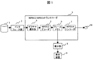
図1は、本発明の第1の実施形態に係るトランスコーダのブロック図を示したものである。図1において、記録媒体1から読み出したストリームを、トランスコーダ3にて符号変換し、出力端子50から出力する。トランスコーダ3は、ピクチャ選別部4、MPEG2デコーダ5、フレームメモリ6、MPEG4エンコーダ7で構成される。また、フレームメモリ6に蓄積された信号は表示部8を介して、表示装置9にて表示される。
【0010】
図1に示したトランスコーダは、記録媒体1に格納されたMP@ML(main profile at main level)のMPEG2ストリーム(以下MPEG2/MP@MLと略記)を、SP(simple profile)のMPEG4ストリーム(以下MPEG4/SPと略記)にトランスコードして出力する場合である。
【0011】
以下具体的に、30フレーム/秒のMPEG2/MP@MLストリームを10フレーム/秒のMPEG4/SPストリームにトランスコードする場合の動作を説明する。まず、DVDなどの記録媒体1に格納されているMPEG2ストリームは、インターフェース部2によって読み出され、ピクチャ選別部4に供給される。ピクチャ選別部4は、入力されたMPEG2ストリームのピクチャヘッダをサーチし、ストリームを構成するフレームまたはフィールド単位の特定の種類のピクチャを抽出してピクチャ数が1/3に間引かれたMPEG2ストリームを生成する。ピクチャ選別部4の詳細構成については後述する。抽出処理の施されたMPEG2ストリームはピクチャ選別部4から出力され、MPEG2デコーダ5に供給される。MPEG2デコーダ5は、入力されたMPEGストリームを復号化し、デジタルビデオ信号の画素値データに変換する。画素値データはフレームメモリ6に蓄積され、表示用同期信号に従って表示部8に読み出され、表示装置9に表示される。同時に、フレームメモリ6の中のデータはMPEG4エンコーダ7に供給され、MPEG4ストリームに変換されて出力端子51に出力される。
【0012】
図2は、図1におけるピクチャ選別部4の構成を示す。ピクチャ選別部4は、分離部41、バッファメモリ42、バッファメモリ読み出し回路43を有する。MPEG2のストリームはオーディオ、ビデオ、付加データなどが多重化されており、これを分離部41でデータの種類ごとに分離し、システムデコードを行ってES(Elementary Stream)を生成する。ビデオのESはバッファメモリ42に蓄えられる。バッファメモリ読み出し回路43はピクチャヘッダサーチの機能を有し、バッファメモリ42内を順にサーチしてピクチャヘッダを検出し、そのピクチャの種類を判別する。判別したピクチャ種類が抽出すべきピクチャ種類であった場合、次のピクチャヘッダの直前までのデータを読み出す。上記手順により、ピクチャ種類によるピクチャの抽出が実現される。
【0013】
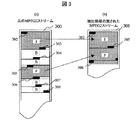
図3は、本実施形態によるピクチャ選別の一例を示すイメージ図である。MPEG2ストリームは、フレーム内符号化方式により符号化されたIピクチャ、過去のフレームを用いて予測符号化されたPピクチャ、過去と未来のフレームを用いて予測符号化されたBピクチャの3種類のピクチャから構成される。図3(a)は、バッファメモリ42に格納されているビデオES300で、図3(b)は、バッファメモリ42から読み出し回路43によってピクチャ選別を行ったビデオES301を示す。入力されたビデオESのうちIピクチャとPピクチャのみを抽出し、Bピクチャを間引く場合である。ビデオES300のピクチャ構成が<IBBPBBPBBPBBPBBIBB……>であれば、ビデオES301のピクチャ構成は<IPPPPI……>となる。
【0014】
バッファメモリ読み出し回路43はまずビデオES300のピクチャヘッダ302を検出し、ピクチャ種類が抽出すべきIピクチャであることを判別して、データの読み出しを開始する。そして、次のピクチャヘッダ303を検出し、ピクチャ種類が間引くべきBピクチャであることを判別して、ピクチャヘッダ303の直前でデータの読み出しを終了する。読み出し回路43は再びヘッダサーチを開始し、ピクチャヘッダ304、305を検出し、ピクチャヘッダ305で始まるピクチャの種類が抽出すべきPピクチャであることを検出してデータの読み出しを開始する。上記手順を繰り返し、ビデオES300からIピクチャとPピクチャのみを抽出したビデオES301を生成する。
【0015】
図3で明らかなように、ビデオES301において、Iピクチャのデータの次にはこれに続く次に抽出されたPピクチャのデータが詰めて連続的に配置される。その結果、ビデオES300の長さに対し、ビデオES301の長さは短縮された部分画像信号となっている。なお、図示していないが、部分画像信号は、抽出されなかったBピクチャの位置を空白データとして構成しても、その後の信号処理(復号処理)で空白部をスキップして処理できるので、実効的な長さが短縮されており支障はない。
【0016】
MPEG2デコーダ5は、供給されたMPEG2ストリームを復号化し、復号化された画像信号を表示するためにフレームメモリ6に格納しておく。格納された画像信号は表示されるまで保持される。この際、フレームメモリがオーバーフローもしくはアンダーフローしないようにするためには、表示スピードと復号化スピードが同じである必要がある。従って、復号化するストリームに含まれるピクチャ総数が多ければ、表示するピクチャは多くなり、復号化に要する時間はピクチャ総数に比例して長くなる。
【0017】
従来の方式でビデオES300をトランスコードする場合、MPEG2デコーダ5は間引き前の全てのピクチャ<IBBPBBPBBPBBPBBI……>を復号化し、その後Bピクチャを間引いて<IPPPPI……>の構成とし、MPEG4エンコーダ7に供給して符号化していた。従って、トランスコードに要する時間は、間引き前の全てのピクチャを含むビデオES300を復号化して表示するのに要する時間と等しくなる。
【0018】
本発明では、ビデオES300からBピクチャを間引いて部分画像信号であるビデオES301を生成してから上記のトランスコード処理を行う。MPEGデコーダ5はビデオES301、つまり<IPPPPI……>のピクチャのみを復号化し、復号化した画像信号をそのままMPEG4エンコーダに供給すればよい。ビデオES301に含まれるピクチャ総数は、ピクチャ抽出回路4によってビデオES300に含まれるピクチャ総数の1/3に減少される。従って、トランスコードに要する時間は、ビデオES300を復号化して表示するのに要する時間の1/3となり、本実施形態によってトランスコードに要する時間を大幅に短縮することができる。この場合、表示部8を経由して表示される映像は、ピクチャ間引き前のストリームをそのまま再生した場合と比較して3倍速の映像となる。
【0019】
図4は、ピクチャ選別部4による好ましいピクチャ抽出条件を示す図である。MPEG予測符号化では、ピクチャ間の動き補償のためのピクチャ間の参照関係を必要とする。図4(a)のように抽出前のストリームにおいては、たとえばBピクチャ102はPピクチャ101とPピクチャ103を参照して予測符号化を行っている。図4(b)、(c)はピクチャ選別部4を用いて抽出したストリームの例である。図4(b)はBピクチャを間引きし、IピクチャとPピクチャを抽出した場合で、抽出されたPピクチャは他の抽出されたピクチャを参照することができ、好適な抽出条件の1つである。しかし図4(c)のような抽出では、抽出されたBピクチャ111、113、Pピクチャ114が参照すべきPピクチャ112はすでに間引かれて参照できない。このため、これらの抽出されたピクチャを復号化することができない。よって、ピクチャ選別部4によってストリームからピクチャを抽出する条件は、抽出後の各ピクチャが参照するピクチャが必ず存在するように抽出することが必要である。
【0020】
他の好適な抽出条件としては、I、P、BピクチャからなるビデオストリームからIピクチャのみを抽出する場合、IピクチャとPピクチャからなるストリームからIピクチャを抽出する場合、Iピクチャのみからなるストリームから特定のIピクチャを抽出してトランスコードを行う場合にも適用可能である。さらに、抽出するピクチャをユーザが指定できるような構成をとることも可能である。
【0021】
上記実施形態では、ピクチャ選別部4の処理スピードについても特徴がある。先に説明したとおり、図3(a)のストリーム(ビデオES)300を図3(b)のストリーム301に間引く場合、各ストリームに含まれるピクチャ総数は1/3に減少する。このピクチャ数の減少の結果、その後の復号化処理時間が短縮できる訳であるが、ピクチャ選別部4の抽出・間引き処理を滞りなく行うためには、ピクチャ選別部4には復号化処理のレートよりも高速にデータを供給する必要がある。前出の<IBBPBBPBBPBBPBBI……>のピクチャ構成を持つストリームからBピクチャを間引いて<IPPPPI……>とする例を引くと、仮にI、P、Bピクチャの符号量が同じであった場合にピクチャ選別部4の抽出・間引き処理を滞りなく行うためには、ピクチャ選別部4には復号化処理の3倍のビットレートでストリームを供給しなければならない。ただし一般的には、Iピクチャの符号量が一番大きく、次いでPピクチャ、Bピクチャの順となるので、供給するストリームのビットレートは3倍より小さくても良い。MPEG2/MP@MLのビットレートは最大15Mbit/secと規定されているので、ピクチャ選別部4にはその3倍のビットレートの45Mbit/secでストリームを供給すればよい。
【0022】
一例として、記録媒体1としてDVD−ROMからの供給を仮定すると、インターフェース部2を経由してピクチャ選別部4に入力できるデータのビットレートは、最大で160Mbit/secとなる。よって、ピクチャ選別部4には上記必要な入力ビットレートでMPEG2ストリームデータを供給することは可能である。また、読み出し回路43の能力は、81MHz動作、16bit処理の場合、ヘッダサーチ処理可能な最大ビットレートはおよそ1Gbit/secとなる。ゆえに、上記入力ビットレートに対して余裕をもってヘッダサーチ処理を行うことが可能である。同様のヘッダサーチをソフトウェアで行う場合、例えば200MHz動作のCPUを用い、1ワードの処理に30サイクルを要するとすると、ヘッダサーチ処理可能な最大ビットレートは106Mbit/secであり、この場合も入力ビットレートに対して十分に処理可能である。
【0023】
次に図5は、本発明の第2の実施形態に係るトランスコーダのブロック図を示したものである。本実施形態は第1の実施形態(図1)におけるピクチャ選別部4をなくし、代わりにインターフェース部2を用いて、記録媒体1からの読み出し時にピクチャの抽出・間引きを行う。記録媒体1には、入力端子51から入力するストリームがインターフェース部2を介して格納される。
【0024】
DVDなどの記録媒体1の中には、MPEG2ストリームと管理情報ファイルが格納されている。管理情報ファイルは、入力端子51から入力されたストリームを記録媒体1に格納する際にインターフェース部2において作成され、ストリームとともに記録される。管理情報ファイルには、各ピクチャのピクチャタイプと格納位置、サイズが記録されている。インターフェース部2は、この管理情報ファイルを参照して抽出するピクチャの位置を特定し、ストリーム中からそのピクチャを抽出する。抽出されたピクチャはMPEG2デコーダ5に供給され、前述の第1の実施形態と同様のプロセスによってトランスコードが行われる。
【0025】
図6は、記録媒体の一例として、DVD Video Recording規格によって規定されるファイル構成を示す。記録媒体上にはDVD_RTAVディレクトリ200があり、その下位の階層にVR_MANGR.IFO201とVR_MOVIE.VRO202の各ファイルが存在する。VR_MOVIE.VRO201はMPEG2ストリームデータであり、VOBU(Video Object Unit)と呼ばれる小単位に分割されて格納されている。各VOBUはそれぞれ1枚のIピクチャを有する。VR_MANGR.IFO202は管理情報ファイルであり、早送り・巻き戻し等の特殊再生に用いるため、VOBU中のIピクチャの位置とサイズがテーブルとして記録されている。従って、Iピクチャのみの抽出を行う場合には、まずVR_MANGR.IFO201を参照してIピクチャの位置を特定し、そこからピクチャサイズ分のデータを読み出せばよい。
【0026】
この実施形態によれば、記録媒体1からの抽出読み出しの段階で短縮した部分画像信号を生成しているので、後続の処理に要する時間を短縮することができる。
【0027】
上記の例はDVD Video Recording規格に準拠した記録媒体について言及したものであるが、ピクチャ種類とその格納位置を示す管理情報をもつ他の記録媒体においても同様に適用可能である。
【0028】
なお、記録媒体1がリムーバブルな記録媒体で、この記録媒体に他装置を用いてストリームの書き込みを行った場合には、管理情報ファイルが存在しない可能性がある。このような場合に備え、格納されているストリームをインターフェース部2が読み出し、ストリーム解析を行って管理情報ファイルを作成して記録媒体に格納することが出来るような機能を備えてもよい。
【0029】
図7は、本発明の第3の実施形態に係る撮像装置のブロック図を示したものである。本実施形態は、第1の実施形態(図1)に示したトランスコーダを用いた撮影装置である。撮像装置30は、第1の実施形態の構成に加え、カメラ部10、ユーザインタフェース20を有する。カメラ部10は撮像部11、MPEG2エンコーダ12により構成される。
【0030】
ユーザが記録媒体1にMPEG2動画を記録する場合、ユーザインタフェース20より記録指示が出され、カメラ部10の撮像部11においてデジタルビデオ信号を生成し、MPEG2エンコーダ12において前記デジタルビデオ信号を符号化してMPEG2ストリームを生成する。そして、前記MPEG2ストリームはインターフェース部2を経由して記録媒体1に記録される。
【0031】
また、記録媒体1に記録されたMPEG2ストリームをMPEG4ストリームにトランスコードする場合、ユーザインタフェース20よりトランスコード指示が出され、第1の実施形態に示したようなプロセスを経てMPEG4ストリームにトランスコードされて出力する。
【0032】
このように本実施形態の撮像装置によれば、撮影した画像を高画質のMPEG2ストリームで記録保存しておくとともに、外部には低ビットレートのMPEG4ストリームに変換して出力することができる。
【0033】
図7では、第1の実施形態(図1)のトランスコーダを用いた撮影装置であるが、この代わりに第2の実施形態(図5)のトランスコーダを用いて撮像装置を構成してもよい。本実施形態のカメラ部10には撮像部11が存在するが、さらに外部から画像信号を受信する受信部を接続し、外部から画像信号を受け取る構成としてもよい。また、外部からMPEG2ストリームを受信する受信部を接続し、外部からMPEG2ストリームを受け取る構成としてもよい。
【0034】
以上の第1ないし第3の実施形態においては、MPEG2圧縮符号化方式からMPEG4へのトランスコードを前提として説明したが、本発明はこれに限定するものではなく、他の圧縮符号化方式を用いた場合にも適用可能である。
【0035】
さらに本発明のトランスコーダは、上記撮像装置以外にも、画像信号(ストリーム)を受信しこれをトランスコードして表示装置等へ出力する受信装置(セットトップボックス)、入力した画像信号をトランスコードして表示する画像表示装置(ディスプレイ)、入力した画像信号をトランスコードして記録媒体(ハードディスク、光ディスク等)に記録する画像記録装置、あるいは各種画像機器を接続して画像信号の供給を行なうホームサーバなどへの適用が可能である。
【0036】
【発明の効果】
本発明によれば、ユーザの使い勝手を向上させるトランスコーダおよび撮像装置を提供することができる。
【図面の簡単な説明】
【図1】本発明の第1の実施形態に係るトランスコーダのブロック図である。
【図2】図1におけるピクチャ選別部4の構成を示した図である。
【図3】図1におけるピクチャ選別の一例を示すイメージ図である。
【図4】図1における好ましいピクチャ抽出条件を示す図である。
【図5】本発明の第2の実施形態に係るトランスコーダのブロック図である。
【図6】図5における記録媒体1のファイル構成の一例を示した図である。
【図7】本発明の第3の実施形態に係る撮像装置のブロック図である。
【符号の説明】
1…記録媒体
2…インターフェース部
3…トランスコーダ
4…ピクチャ選別部
5…MPEG2デコーダ
6…フレームメモリ
7…MPEG4エンコーダ
8…表示部
9…表示装置
10…カメラ部
11…撮像部
12…MPEG2エンコーダ
20…ユーザインタフェース
30…撮像装置[0001]
BACKGROUND OF THE INVENTION
The present invention relates to a transcoder that converts a coding method of an image signal, an imaging device using the transcoder, and a signal processing device.
[0002]
[Prior art]
In recent years, a technique for compressing and encoding a moving image signal by a compression method such as MPEG and recording it on a recording medium, or a technique for transmitting a compression-encoded signal via a communication medium such as the Internet or wireless is used in various fields. ing. For example, MPEG2-Video (ISO / IEC13818-2) is used for DVD recording and reproduction. Also, MPEG4-Video (ISO / IEC 14496-2) is applied for wireless communication and Internet use. In addition, a wide variety of encoding schemes have been proposed. Along with the diversification of encoding methods, transcoding for converting data between these methods is necessary, and improvement of the function is required. In particular, reducing the time required for the transcoding process leads to an increase in convenience on the user side.
[0003]
Regarding the speeding up of transcoding, there is a technique disclosed in
[0004]
[Patent Document 1]
Japanese Patent Application Laid-Open No. 2002-152755
[Problems to be solved by the invention]
According to the technique described in
[0006]
An object of the present invention is to solve the above-mentioned problems, shorten the time required for transcoding an image signal, and improve the usability of the user.
[0007]
[Means for Solving the Problems]
In the present invention, the above problem can be improved by the following configuration, for example, but is not limited to this configuration.
The problem is, for example, signal processing in which a first image signal encoded by a first compression encoding method is input and converted into a second image signal encoded by a second compression encoding method. An apparatus for extracting a specific type of picture in frame or field units constituting the image signal from the first image signal, and generating a partial image signal; A stream supply unit for supplying a first image signal; a first decoding unit for decoding the partial image signal generated by the picture selection unit; and a second compression code for the decoded image signal. A first encoding unit that encodes using the encoding method, and the picture selection unit generates a partial image signal in which the effective length of the image signal is shortened using the extracted picture,
The stream supply unit has a bit rate higher than a rate at which the partial image signal is decoded by the first decoding unit so as to supplement a code amount of a picture not extracted by the picture selection unit. This can be improved by a signal processing device that supplies the first image signal to the picture selection unit.
[0009]
DETAILED DESCRIPTION OF THE INVENTION
FIG. 1 is a block diagram of a transcoder according to the first embodiment of the present invention. In FIG. 1, the stream read from the
[0010]
The transcoder shown in FIG. 1 converts an MPEG @ ML (main profile at main level) MPEG2 stream (hereinafter abbreviated as MPEG2 / MP @ ML) stored in the
[0011]
The operation in the case of transcoding an MPEG2 / MP @ ML stream of 30 frames / second into an MPEG4 / SP stream of 10 frames / second will be specifically described below. First, the MPEG2 stream stored in the
[0012]
FIG. 2 shows the configuration of the picture selection unit 4 in FIG. The picture selection unit 4 includes a
[0013]
FIG. 3 is an image diagram showing an example of picture selection according to the present embodiment. An MPEG2 stream is divided into three types: an I picture encoded by an intraframe encoding method, a P picture that is predictively encoded using past frames, and a B picture that is predictively encoded using past and future frames. Consists of pictures. 3A shows a
[0014]
The buffer
[0015]
As apparent from FIG. 3, in the
[0016]
The MPEG2 decoder 5 decodes the supplied MPEG2 stream and stores it in the frame memory 6 in order to display the decoded image signal. The stored image signal is held until it is displayed. At this time, in order to prevent the frame memory from overflowing or underflowing, the display speed and the decoding speed need to be the same. Therefore, if the total number of pictures included in the stream to be decoded is large, the number of pictures to be displayed increases, and the time required for decoding becomes longer in proportion to the total number of pictures.
[0017]
When transcoding the
[0018]
In the present invention, the B picture is thinned out from the
[0019]
FIG. 4 is a diagram showing preferable picture extraction conditions by the picture selection unit 4. MPEG predictive coding requires a reference relationship between pictures for motion compensation between pictures. In the stream before extraction as shown in FIG. 4A, for example, the
[0020]
As another preferable extraction condition, when extracting only an I picture from a video stream consisting of I, P, and B pictures, when extracting an I picture from a stream consisting of an I picture and a P picture, a stream consisting only of the I picture The present invention can also be applied to a case where a specific I picture is extracted from the image and transcoding is performed. Further, it is possible to adopt a configuration in which the user can specify the picture to be extracted.
[0021]
The above embodiment is also characterized by the processing speed of the picture selection unit 4. As described above, when the stream (video ES) 300 in FIG. 3A is thinned out to the
[0022]
As an example, assuming supply from a DVD-ROM as the
[0023]
Next, FIG. 5 is a block diagram of a transcoder according to the second embodiment of the present invention. In the present embodiment, the picture selection unit 4 in the first embodiment (FIG. 1) is eliminated, and instead the
[0024]
An MPEG2 stream and a management information file are stored in the
[0025]
FIG. 6 shows a file structure defined by the DVD Video Recording standard as an example of a recording medium. There is a
[0026]
According to this embodiment, since the partial image signal shortened at the stage of extraction and reading from the
[0027]
Although the above example refers to a recording medium that complies with the DVD Video Recording standard, it can be similarly applied to other recording media having management information indicating picture types and their storage positions.
[0028]
If the
[0029]
FIG. 7 shows a block diagram of an imaging apparatus according to the third embodiment of the present invention. This embodiment is an imaging apparatus using the transcoder shown in the first embodiment (FIG. 1). The
[0030]
When a user records an MPEG2 moving image on the
[0031]
Further, when the MPEG2 stream recorded on the
[0032]
As described above, according to the image pickup apparatus of the present embodiment, a shot image can be recorded and stored as a high-quality MPEG2 stream, and can be converted to a low bit rate MPEG4 stream for output.
[0033]
In FIG. 7, the imaging apparatus uses the transcoder of the first embodiment (FIG. 1). Alternatively, the imaging apparatus may be configured using the transcoder of the second embodiment (FIG. 5). Good. The camera unit 10 of the present embodiment includes the imaging unit 11, but may be configured to connect a receiving unit that receives an image signal from the outside and receive the image signal from the outside. In addition, a receiving unit that receives an MPEG2 stream from the outside may be connected to receive the MPEG2 stream from the outside.
[0034]
In the first to third embodiments described above, the transcoding from the MPEG2 compression coding system to the MPEG4 has been described. However, the present invention is not limited to this, and other compression coding systems are used. It is also applicable when
[0035]
Further, the transcoder according to the present invention, in addition to the imaging device, receives a video signal (stream), transcodes it and outputs it to a display device or the like, and transcodes the input video signal. An image display device (display) for displaying images, an image recording device for transcoding input image signals and recording them on a recording medium (hard disk, optical disk, etc.), or a home for connecting various image devices to supply image signals It can be applied to servers.
[0036]
【The invention's effect】
ADVANTAGE OF THE INVENTION According to this invention, the transcoder and imaging device which improve a user's usability can be provided.
[Brief description of the drawings]
FIG. 1 is a block diagram of a transcoder according to a first embodiment of the present invention.
FIG. 2 is a diagram illustrating a configuration of a picture selection unit 4 in FIG.
FIG. 3 is an image diagram showing an example of picture selection in FIG. 1;
FIG. 4 is a diagram showing preferable picture extraction conditions in FIG. 1;
FIG. 5 is a block diagram of a transcoder according to a second embodiment of the present invention.
6 is a diagram showing an example of a file configuration of the
FIG. 7 is a block diagram of an imaging apparatus according to a third embodiment of the present invention.
[Explanation of symbols]
DESCRIPTION OF
Claims (10)
上記第1の画像信号から、該画像信号を構成するフレームまたはフィールド単位の特定の種類のピクチャを抽出し、部分画像信号を生成するピクチャ選別部と、
該ピクチャ選別部に上記第1の画像信号を供給するストリーム供給部と、
該ピクチャ選別部にて生成された部分画像信号を復号化する第1の復号化部と、
該復号化された画像信号を第2の圧縮符号化方式にて符号化する第1の符号化部と、
を備え、
上記ピクチャ選別部は、抽出されるピクチャを用いて画像信号の実効長さを短縮した部分画像信号を生成し、
上記ストリーム供給部は、該ピクチャ選別部が抽出処理を滞りなく行うために、前記第1の復号化部で前記部分画像信号が復号化されるレートにピクチャの間引き率の逆数をかけたレートで、前記第1の画像信号を前記ピクチャ選別部へ供給すること
を特徴とした信号処理装置。A signal processing device that receives a first image signal encoded by a first compression encoding method and converts the first image signal into a second image signal encoded by a second compression encoding method,
A picture selection unit that extracts a specific type of picture in units of frames or fields constituting the image signal from the first image signal, and generates a partial image signal;
A stream supply unit for supplying the first image signal to the picture selection unit;
A first decoding unit for decoding the partial image signal generated by the picture selection unit;
A first encoding unit that encodes the decoded image signal by a second compression encoding method ;
With
The picture selection unit generates a partial image signal in which the effective length of the image signal is shortened using the extracted picture,
The stream supply unit has a rate obtained by multiplying a rate at which the partial image signal is decoded by the first decoding unit by a reciprocal of a picture decimation rate in order for the picture selection unit to perform extraction processing without delay. The signal processing apparatus supplies the first image signal to the picture selection unit.
前記ピクチャ選別部は、抽出後の各ピクチャには互いに動き補償のために用いる参照先のピクチャが含まれるように抽出することを特徴とした信号処理装置。The signal processing device according to claim 1,
The signal selection device is characterized in that the picture selection unit extracts each picture after extraction so that reference pictures used for motion compensation are included in each other.
前記第1、第2の圧縮符号化方式は、それぞれMPEG2、MPEG4方式であり、
前記ピクチャ選別部は、IピクチャとPピクチャを抽出して部分画像信号を生成することを特徴とした信号処理装置。The signal processing apparatus according to claim 1 or 2,
The first and second compression encoding methods are MPEG2 and MPEG4, respectively.
The signal processing device, wherein the picture selection unit extracts an I picture and a P picture to generate a partial image signal.
前記ピクチャ選別部は、抽出するピクチャの種類をユーザが指定できることを特徴とした信号処理装置。The signal processing device according to any one of claims 1 to 3,
A signal processing apparatus characterized in that the picture selection unit allows a user to specify the type of picture to be extracted.
前記第1の復号化部にて復号化された画像信号を記憶するフレームメモリと、
該フレームメモリから画像信号を読み出し表示装置へ出力する出力部とを備え、
前記出力部は、該表示装置にトランスコード中の画像信号を出力することを特徴とする信号処理装置。The signal processing device according to any one of claims 1 to 4,
A frame memory for storing the image signal decoded by the first decoding unit;
An output unit that reads an image signal from the frame memory and outputs the image signal to a display device;
The signal processing device, wherein the output unit outputs an image signal in transcoding to the display device.
被写体を撮影する撮像部と、
撮像部から供給される画像信号を前記第1の圧縮符号化方式にて符号化する第2の符号化部と、
該第2の符号化部によって符号化された第1の画像信号を記録媒体に記録し再生する記録再生部とを備え、
該記録媒体から再生した第1の画像信号を前記信号処理装置に供給することを特徴とする撮像装置。An imaging apparatus using the signal processing apparatus according to any one of claims 1 to 5,
An imaging unit for photographing a subject;
A second encoding unit that encodes an image signal supplied from the imaging unit using the first compression encoding method;
A recording / reproducing unit for recording and reproducing the first image signal encoded by the second encoding unit on a recording medium,
An image pickup apparatus for supplying a first image signal reproduced from the recording medium to the signal processing apparatus.
外部から入力される画像信号を受信する受信部を備え、
前記第2の符号化部は、該受信部から供給される画像信号を前記第1の圧縮符号化方式にて符号化することを特徴とする撮像装置。The imaging apparatus according to claim 6,
A receiving unit that receives an image signal input from the outside,
The second encoding unit encodes an image signal supplied from the reception unit using the first compression encoding method.
外部から入力される第1の圧縮符号化方式にて符号化された第1の画像信号を受信する受信部を備え、
前記記録再生部は、該受信部から供給される第1の画像信号を記録媒体に記録し再生することを特徴とする撮像装置。The imaging apparatus according to claim 6,
A receiving unit for receiving a first image signal encoded by a first compression encoding method input from the outside;
The recording / reproducing unit records and reproduces the first image signal supplied from the receiving unit on a recording medium.
前記記録再生部は、前記記録媒体に記録されている第1の画像信号から管理情報を生成し、該記録媒体に格納することを特徴とする撮像装置。The imaging apparatus according to any one of claims 6 to 8,
The imaging apparatus, wherein the recording / reproducing unit generates management information from a first image signal recorded on the recording medium and stores the management information in the recording medium.
第1の圧縮符号化方式にて符号化された第1の画像信号が入力され、第2の圧縮符号化方式にて符号化された第2の画像信号に変換して外部機器へ出力する信号処理装置。A signal processing device according to any one of claims 1 to 5,
The first image signal encoded by the first compression encoding method is input, converted into the second image signal encoded by the second compression encoding method, and output to an external device Processing equipment.
Priority Applications (4)
| Application Number | Priority Date | Filing Date | Title |
|---|---|---|---|
| JP2003207246A JP4403737B2 (en) | 2003-08-12 | 2003-08-12 | Signal processing apparatus and imaging apparatus using the same |
| CNB2004100390367A CN1295932C (en) | 2003-08-12 | 2004-01-20 | Transcoder and imaging apparatus for converting an encoding system of video signal |
| US10/768,757 US20050047501A1 (en) | 2003-08-12 | 2004-01-30 | Transcoder and imaging apparatus for converting an encoding system of video signal |
| US12/839,540 US8355439B2 (en) | 2003-08-12 | 2010-07-20 | Transcoder and imaging apparatus for converting an encoding system of video signal |
Applications Claiming Priority (1)
| Application Number | Priority Date | Filing Date | Title |
|---|---|---|---|
| JP2003207246A JP4403737B2 (en) | 2003-08-12 | 2003-08-12 | Signal processing apparatus and imaging apparatus using the same |
Publications (2)
| Publication Number | Publication Date |
|---|---|
| JP2005064569A JP2005064569A (en) | 2005-03-10 |
| JP4403737B2 true JP4403737B2 (en) | 2010-01-27 |
Family
ID=34208954
Family Applications (1)
| Application Number | Title | Priority Date | Filing Date |
|---|---|---|---|
| JP2003207246A Expired - Fee Related JP4403737B2 (en) | 2003-08-12 | 2003-08-12 | Signal processing apparatus and imaging apparatus using the same |
Country Status (3)
| Country | Link |
|---|---|
| US (2) | US20050047501A1 (en) |
| JP (1) | JP4403737B2 (en) |
| CN (1) | CN1295932C (en) |
Families Citing this family (24)
| Publication number | Priority date | Publication date | Assignee | Title |
|---|---|---|---|---|
| JP2006279262A (en) * | 2005-03-28 | 2006-10-12 | Pioneer Electronic Corp | Coded video conversion apparatus, conversion method and program therefor |
| JP4534935B2 (en) * | 2005-10-04 | 2010-09-01 | 株式会社日立製作所 | Transcoder, recording apparatus, and transcoding method |
| JP4600997B2 (en) * | 2005-11-08 | 2010-12-22 | Kddi株式会社 | Encoding method converter |
| FR2908949A1 (en) * | 2006-11-16 | 2008-05-23 | Thomson Licensing Sas | PROCESS FOR TRANSCODING DATA FROM STANDARD MPEG2 TO STANDARD MPEG4. |
| JP4829767B2 (en) * | 2006-12-18 | 2011-12-07 | 株式会社日立製作所 | Video recording / reproducing apparatus and video special reproducing method thereof |
| US9398346B2 (en) | 2007-05-04 | 2016-07-19 | Time Warner Cable Enterprises Llc | Methods and apparatus for predictive capacity allocation |
| US8233527B2 (en) * | 2007-05-11 | 2012-07-31 | Advanced Micro Devices, Inc. | Software video transcoder with GPU acceleration |
| US8861591B2 (en) * | 2007-05-11 | 2014-10-14 | Advanced Micro Devices, Inc. | Software video encoder with GPU acceleration |
| US20080278595A1 (en) * | 2007-05-11 | 2008-11-13 | Advance Micro Devices, Inc. | Video Data Capture and Streaming |
| US9060208B2 (en) | 2008-01-30 | 2015-06-16 | Time Warner Cable Enterprises Llc | Methods and apparatus for predictive delivery of content over a network |
| JPWO2009119721A1 (en) * | 2008-03-26 | 2011-07-28 | 日本電気株式会社 | Video transcoder monitoring device, method and monitoring program thereof |
| JPWO2009119807A1 (en) * | 2008-03-28 | 2011-07-28 | 日本電気株式会社 | Video transcoder monitoring device, method and program thereof |
| US9215423B2 (en) | 2009-03-30 | 2015-12-15 | Time Warner Cable Enterprises Llc | Recommendation engine apparatus and methods |
| US11076189B2 (en) | 2009-03-30 | 2021-07-27 | Time Warner Cable Enterprises Llc | Personal media channel apparatus and methods |
| US9027062B2 (en) * | 2009-10-20 | 2015-05-05 | Time Warner Cable Enterprises Llc | Gateway apparatus and methods for digital content delivery in a network |
| US8396055B2 (en) | 2009-10-20 | 2013-03-12 | Time Warner Cable Inc. | Methods and apparatus for enabling media functionality in a content-based network |
| US8743178B2 (en) * | 2010-01-05 | 2014-06-03 | Dolby Laboratories Licensing Corporation | Multi-view video format control |
| US8997136B2 (en) | 2010-07-22 | 2015-03-31 | Time Warner Cable Enterprises Llc | Apparatus and methods for packetized content delivery over a bandwidth-efficient network |
| CN101951504B (en) * | 2010-09-07 | 2012-07-25 | 中国科学院深圳先进技术研究院 | Method and system for transcoding multimedia slices based on overlapping boundaries |
| US9602414B2 (en) | 2011-02-09 | 2017-03-21 | Time Warner Cable Enterprises Llc | Apparatus and methods for controlled bandwidth reclamation |
| US8978079B2 (en) | 2012-03-23 | 2015-03-10 | Time Warner Cable Enterprises Llc | Apparatus and methods for managing delivery of content in a network with limited bandwidth using pre-caching |
| US9467723B2 (en) | 2012-04-04 | 2016-10-11 | Time Warner Cable Enterprises Llc | Apparatus and methods for automated highlight reel creation in a content delivery network |
| US20140082645A1 (en) | 2012-09-14 | 2014-03-20 | Peter Stern | Apparatus and methods for providing enhanced or interactive features |
| US10116676B2 (en) | 2015-02-13 | 2018-10-30 | Time Warner Cable Enterprises Llc | Apparatus and methods for data collection, analysis and service modification based on online activity |
Family Cites Families (18)
| Publication number | Priority date | Publication date | Assignee | Title |
|---|---|---|---|---|
| CN1223768A (en) * | 1996-08-21 | 1999-07-21 | 株式会社日立制作所 | Electronic camera with liquid crystal display |
| JP2000244872A (en) | 1999-02-19 | 2000-09-08 | Toshiba Corp | Transcoder device |
| JP3789048B2 (en) | 1999-02-22 | 2006-06-21 | 株式会社東芝 | Video re-encoding device |
| US7088725B1 (en) * | 1999-06-30 | 2006-08-08 | Sony Corporation | Method and apparatus for transcoding, and medium |
| JP4153150B2 (en) | 1999-09-10 | 2008-09-17 | 株式会社エヌ・ティ・ティ・ドコモ | Transcoding method and transcoding apparatus for moving image encoded data |
| WO2001041000A1 (en) * | 1999-11-30 | 2001-06-07 | New Media Technology, Corp. | System and method for computer-assisted manual and automatic logging of time-based media |
| JP2001285863A (en) * | 2000-03-30 | 2001-10-12 | Sony Corp | Device and method for converting image information |
| JP2001285823A (en) | 2000-03-30 | 2001-10-12 | Toshiba Corp | Method and device for reproducing and distributing video |
| US6647061B1 (en) * | 2000-06-09 | 2003-11-11 | General Instrument Corporation | Video size conversion and transcoding from MPEG-2 to MPEG-4 |
| CN1253006C (en) * | 2000-10-24 | 2006-04-19 | 皇家菲利浦电子有限公司 | Method of transcoding and transcoding device with embedded filters |
| JP2002152755A (en) * | 2000-11-09 | 2002-05-24 | Nippon Telegr & Teleph Corp <Ntt> | Transcode method between video streams, and transcoder, and recording medium with program for the transcode method recorded thereon |
| JP2002152759A (en) * | 2000-11-10 | 2002-05-24 | Sony Corp | Image information converter and image information conversion method |
| US20020194589A1 (en) * | 2001-05-08 | 2002-12-19 | Cristofalo Michael | Technique for optimizing the delivery of advertisements and other programming segments by making bandwidth tradeoffs |
| US7706445B2 (en) * | 2001-05-31 | 2010-04-27 | Sanyo Electric Co., Ltd. | Image processing employing picture type conversion |
| JP2003087785A (en) * | 2001-06-29 | 2003-03-20 | Toshiba Corp | Method of converting format of encoded video data and apparatus therefor |
| JP2003087797A (en) * | 2001-09-06 | 2003-03-20 | Sony Corp | Apparatus and method for picture information conversion, picture information conversion program, and recording medium |
| US7173947B1 (en) * | 2001-11-28 | 2007-02-06 | Cisco Technology, Inc. | Methods and apparatus to evaluate statistical remultiplexer performance |
| US7469012B2 (en) * | 2002-05-14 | 2008-12-23 | Broadcom Corporation | System and method for transcoding entropy-coded bitstreams |
-
2003
- 2003-08-12 JP JP2003207246A patent/JP4403737B2/en not_active Expired - Fee Related
-
2004
- 2004-01-20 CN CNB2004100390367A patent/CN1295932C/en not_active Expired - Fee Related
- 2004-01-30 US US10/768,757 patent/US20050047501A1/en not_active Abandoned
-
2010
- 2010-07-20 US US12/839,540 patent/US8355439B2/en not_active Expired - Fee Related
Also Published As
| Publication number | Publication date |
|---|---|
| CN1295932C (en) | 2007-01-17 |
| US20100283869A1 (en) | 2010-11-11 |
| CN1581981A (en) | 2005-02-16 |
| US8355439B2 (en) | 2013-01-15 |
| JP2005064569A (en) | 2005-03-10 |
| US20050047501A1 (en) | 2005-03-03 |
Similar Documents
| Publication | Publication Date | Title |
|---|---|---|
| JP4403737B2 (en) | Signal processing apparatus and imaging apparatus using the same | |
| EP0895694B1 (en) | System and method for creating trick play video streams from a compressed normal play video bitstream | |
| US6078616A (en) | Methods and apparatus for error concealment utilizing temporal domain motion vector estimation | |
| KR101227330B1 (en) | Picture coding apparatus and picture decoding apparatus | |
| JP4515465B2 (en) | Moving picture photographing apparatus and moving picture photographing method, moving picture reproducing apparatus and moving picture reproducing method for reproducing a video signal recorded on a recording medium | |
| JP3147792B2 (en) | Video data decoding method and apparatus for high-speed playback | |
| JPH1155649A (en) | Method and device for communicating image | |
| JP4902854B2 (en) | Moving picture decoding apparatus, moving picture decoding method, moving picture decoding program, moving picture encoding apparatus, moving picture encoding method, moving picture encoding program, and moving picture encoding / decoding apparatus | |
| JP4289055B2 (en) | Transcoder and recording / reproducing apparatus using the same | |
| EP1926104A1 (en) | Encoding device, decoding device, recording device, audio/video data transmission system | |
| KR100394013B1 (en) | Apparatus for transcoding video snap image | |
| JP4528043B2 (en) | Video signal conversion apparatus, conversion method, and video signal recording apparatus using the same | |
| JP2989417B2 (en) | Digital information playback device | |
| JP4178521B2 (en) | Encoded video signal recording method and video signal encoding apparatus | |
| JP2003339003A (en) | Image photographing distribution apparatus and image photographing distribution method | |
| JP3897783B2 (en) | Image processing apparatus, control method therefor, computer program, and computer-readable storage medium | |
| JPH1168881A (en) | Data stream processor and its method | |
| JP2011091592A (en) | Image encoder, code converter, image recorder, image reproduction device, image encoding method, and integrated circuit | |
| JP2006180315A (en) | Moving picture photographing device and moving picture reproducing device, and moving picture photographing method and moving picture reproducing method | |
| JP2002112183A (en) | Mpeg image data recording method | |
| JP2013102295A (en) | Image encoding method, image encoder and program, image decoding method, and image decoder and program | |
| JP3381723B2 (en) | Data generator | |
| JP3381725B2 (en) | Data recording device | |
| JP3381724B2 (en) | Data recording method | |
| JP2000188736A (en) | Recording device, recording method, reproducing device, reproducing method and recording medium |
Legal Events
| Date | Code | Title | Description |
|---|---|---|---|
| RD01 | Notification of change of attorney |
Free format text: JAPANESE INTERMEDIATE CODE: A7421 Effective date: 20060421 |
|
| A621 | Written request for application examination |
Free format text: JAPANESE INTERMEDIATE CODE: A621 Effective date: 20060724 |
|
| A977 | Report on retrieval |
Free format text: JAPANESE INTERMEDIATE CODE: A971007 Effective date: 20080522 |
|
| A131 | Notification of reasons for refusal |
Free format text: JAPANESE INTERMEDIATE CODE: A131 Effective date: 20080610 |
|
| A521 | Written amendment |
Free format text: JAPANESE INTERMEDIATE CODE: A523 Effective date: 20080807 |
|
| A131 | Notification of reasons for refusal |
Free format text: JAPANESE INTERMEDIATE CODE: A131 Effective date: 20090310 |
|
| A521 | Written amendment |
Free format text: JAPANESE INTERMEDIATE CODE: A523 Effective date: 20090427 |
|
| A521 | Written amendment |
Free format text: JAPANESE INTERMEDIATE CODE: A523 Effective date: 20090427 |
|
| TRDD | Decision of grant or rejection written | ||
| A01 | Written decision to grant a patent or to grant a registration (utility model) |
Free format text: JAPANESE INTERMEDIATE CODE: A01 Effective date: 20091013 |
|
| A01 | Written decision to grant a patent or to grant a registration (utility model) |
Free format text: JAPANESE INTERMEDIATE CODE: A01 |
|
| A61 | First payment of annual fees (during grant procedure) |
Free format text: JAPANESE INTERMEDIATE CODE: A61 Effective date: 20091026 |
|
| FPAY | Renewal fee payment (event date is renewal date of database) |
Free format text: PAYMENT UNTIL: 20121113 Year of fee payment: 3 |
|
| FPAY | Renewal fee payment (event date is renewal date of database) |
Free format text: PAYMENT UNTIL: 20121113 Year of fee payment: 3 |
|
| FPAY | Renewal fee payment (event date is renewal date of database) |
Free format text: PAYMENT UNTIL: 20121113 Year of fee payment: 3 |
|
| FPAY | Renewal fee payment (event date is renewal date of database) |
Free format text: PAYMENT UNTIL: 20131113 Year of fee payment: 4 |
|
| S111 | Request for change of ownership or part of ownership |
Free format text: JAPANESE INTERMEDIATE CODE: R313111 |
|
| LAPS | Cancellation because of no payment of annual fees |